

Avaya Scopia XT Deluxe Camera Quick Setup Manual
Avaya Scopia® XT Deluxe Camera
Quick Setup Guide
Congratulations on purchasing your
PTZ Deluxe Camera for the Avaya
Scopia® XT Series. This brings a high
quality full HD video source to your
endpoint, with HD 1080p 60 frames
per second (fps), including 12x Optical
Zoom, 4x Digital zoom (total 48x), and
an optimal horizontal field of view for
video conferencing rooms.
Package Content:
• Avaya Scopia XT Deluxe Camera
• First camera cable: 2.5m triple
camera cable, including power,
VISCA and DVI-D/HDMI
Help
CAUTION: the mains
cable is used as a
disconnecting device,
use therefore an easily
accessible outlet
located near the
device for the power
supply connection.
Never remove the
mains plug while the
device is connected.
CAUTION: the mains
cable is used as a
disconnecting device,
use therefore an easily
accessible outlet
located near the
device for the power
supply connection.
Never remove the
mains plug while the
device is connected.
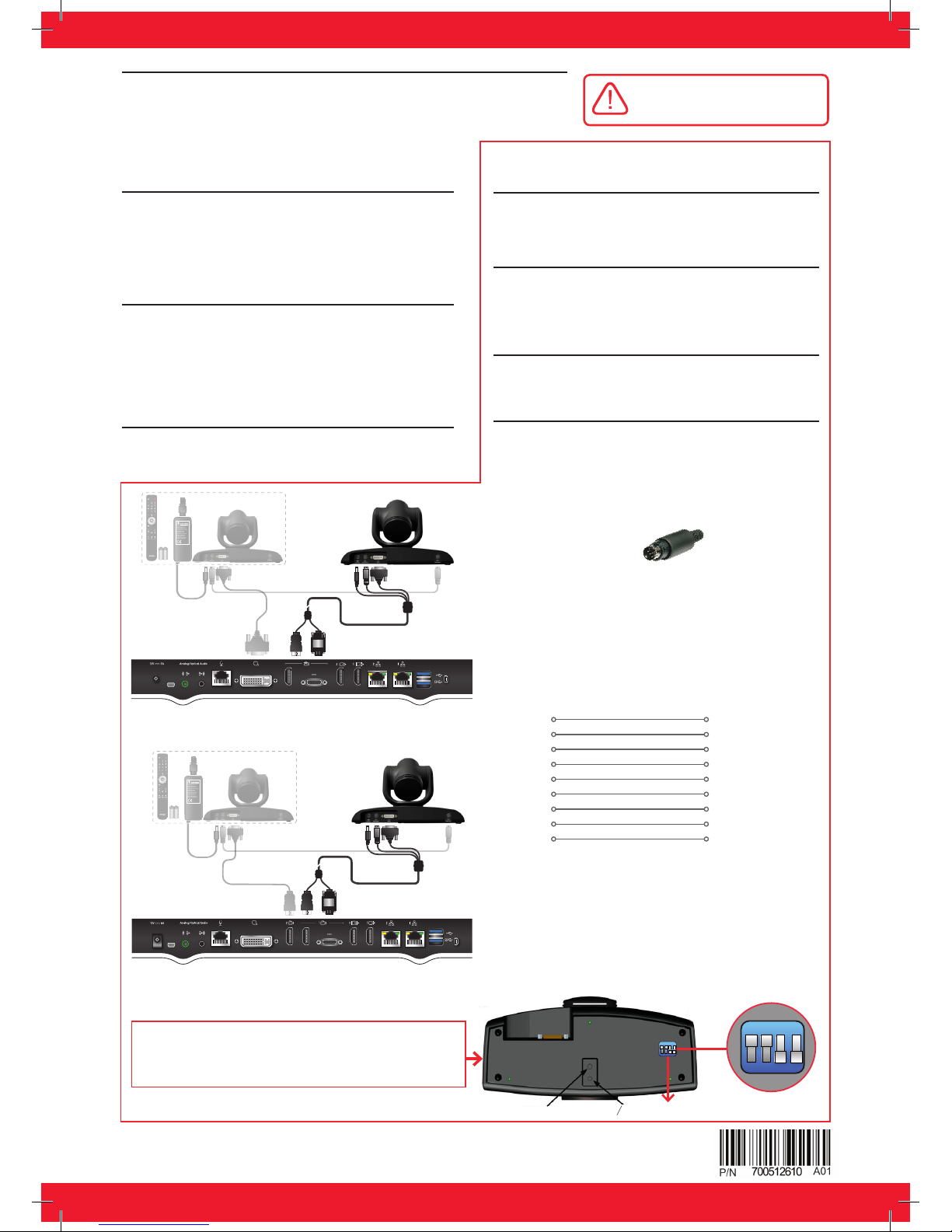
VISCA Cable
VISCA Control is a standard protocol to control
PTZ Cameras.
You may buy a VISCA cross cable from a third
party or make you own cable if you’re planning
to position the optional camera far away from the
Codec Unit.
The VISCA cross cable is an 8-pin mini-DIN male to
mini-DIN male cable with below Pinout diagram
VISCA - IN
1 One
2 Two
3 Three
4 Four
5 Five
6 Six
7 Seven
8 Eight
SHIELD
VISCA - OUT
2 Two
1 One
5 Five
4 Four
3 Three
6 Six
7 Seven
8 Eight
SHIELD
To control the optional camera from your XT
Series endpoint, you need to connect a VISCA
cable between the two cascaded cameras.
Step 1
Insert the three connectors to their sockets at rear of
the camera:
• The DVI connector to the DVI socket.
• The 8-pin connector to the Camera Ctrl IN socket.
• The power connector to the DC IN 12V socket.
Step 1
Connect the Deluxe Camera to the XT5000 Codec
Unit’s DVI input (instead of connecting a PC), or to the
second HDMI input of XT7100.
Step 2
Connect the VISCA control cross cable between the
Camera Ctrl Out of first camera
with Camera Ctrl In of second camera.
Step 3
Connect the power supply of the optional camera
to the mains, then switch on the Codec Unit.
Step 4
Configure the optional camera in the GUI section
“IO connections –> cameras” as explained in the
Administrator guide.
Step 2
Attach the two connectors to the camera sockets at
the rear of the XT Series endpoint (XT4000, XT5000,
XT7000 or XT Executive 240):
• The HDMI connector to the vertical socket
• The connector for power and serial control to the
Step 3
Check that HD1 camera is enabled in the menu
Configure > Advanced > I/O connections >
Camera > HD1
2. Use Deluxe Camera as additional camera1. Use Deluxe Camera as main camera
CAUTION: Make sure all units are
switched off whenever connecting
or disconnecting devices.
Setting Up this Device
Scopia XT Deluxe Camera can be used as first camera on Scopia XT5000
Series, XT7000 Series, XT4000 Series and XT Executive 240, or as
additional camera on XT5000 and XT7000. Please follow the below
instructions to connect and use XT Deluxe Camera.
NOTES:
If multiple cameras are cascaded using VISCA daisy chain,
all must be the same model (all Premium Cameras or all
Deluxe Cameras).
If the Deluxe camera is not controlled through the VISCA
serial control, it can be controlled using the XT Remote
Control, selecting the IDs 97 / 98 / 99.
Power supply, VISCA cross cable, and HDMI to DVI used
to connect the optional camera are provided with Camera
Cable kit, to be purchased separately (not included in the
XT Deluxe Camera box).
The dip switches 1 and 2 at the bottom of the camera
should be set to reflect the selected XT Remote Control ID.
ID97=DIP1 OFF and DIP2 OFF (default). ID98= DIP1 ON
and DIP2 OFF. ID99 = DIP1 OFF and DIP2 ON.
© 2016 Avaya Inc. All Rights Reserved.
Avaya and the Avaya logo are trademarks of Avaya Inc. and are registered in the United States and other countries.
All other trademarks identified by ®, TM, or SM are registered marks, trademarks, and service marks,
respectively, of Avaya Inc. 06/16 • 700512610_QSG_XT_Deluxe_Cmaera
XT5000 Series Codec Unit
XT7000 Series Codec Unit
VISCA Cable
VISCA Cable
horizontal socket.
DIP 1 - DI P2 : To sel ec t IR ID 97,98 ,99
ON
1 2 3 4
1/4-20UNC
05
ON
1 2 3 4
 Loading...