

Avaya Scopia XT Camera Switch Quick Setup Manual
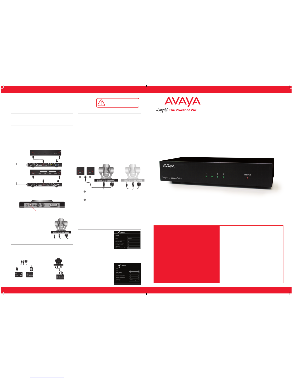
Avaya Scopia® XT Camera Switch
Package Content:
• Avaya Scopia XT Camera Switch
• Cable USB 40cm
• Cable HDMI M/M, 40cm
Step 1. System Installation
Step 4.
Step 8.
Step 9.
Avaya Scopia XT Camera Switch
enables all the endpoints of Avaya
Scopia XT5000 and XT7000 series
to be connected with up to four
HD Cameras or four generic HDMI
devices (such as DVD and generic
media players). The Avaya Scopia XT
Camera Switch is fully powered and
controlled from the Avaya Scopia
XT endpoint. The switch can be
controlled from XT User Interface
and Remote Control.
Quick Setup Guide
Step 2.
1234
HDMI USB
1234
HDMI USB
DC IN 12V IN RS-232C OUT DVI
IR SELECT
1 2 3
1
2
3
4
5
6
7
8
9
SYSTEM
SELECT
Step 5.
1
1
2
DC IN 12V IN RS-232C OUT DVI
IR SELECT
1 2 3
1
2
3
4
5
6
7
8
9
SYSTEM
SELECT
DC IN 12V IN RS-232C OUT DVI
IR SELECT
1 2 3
1
2
3
4
5
6
7
8
9
SYSTEM
SELECT
1
1
Second Camera First Camera
Step 3.
DC IN 12V IN RS-232C OUT DVI
IR SELECT
1 2 3
1
2
3
4
5
6
7
8
9
SYSTEM
SELECT
Step 6.
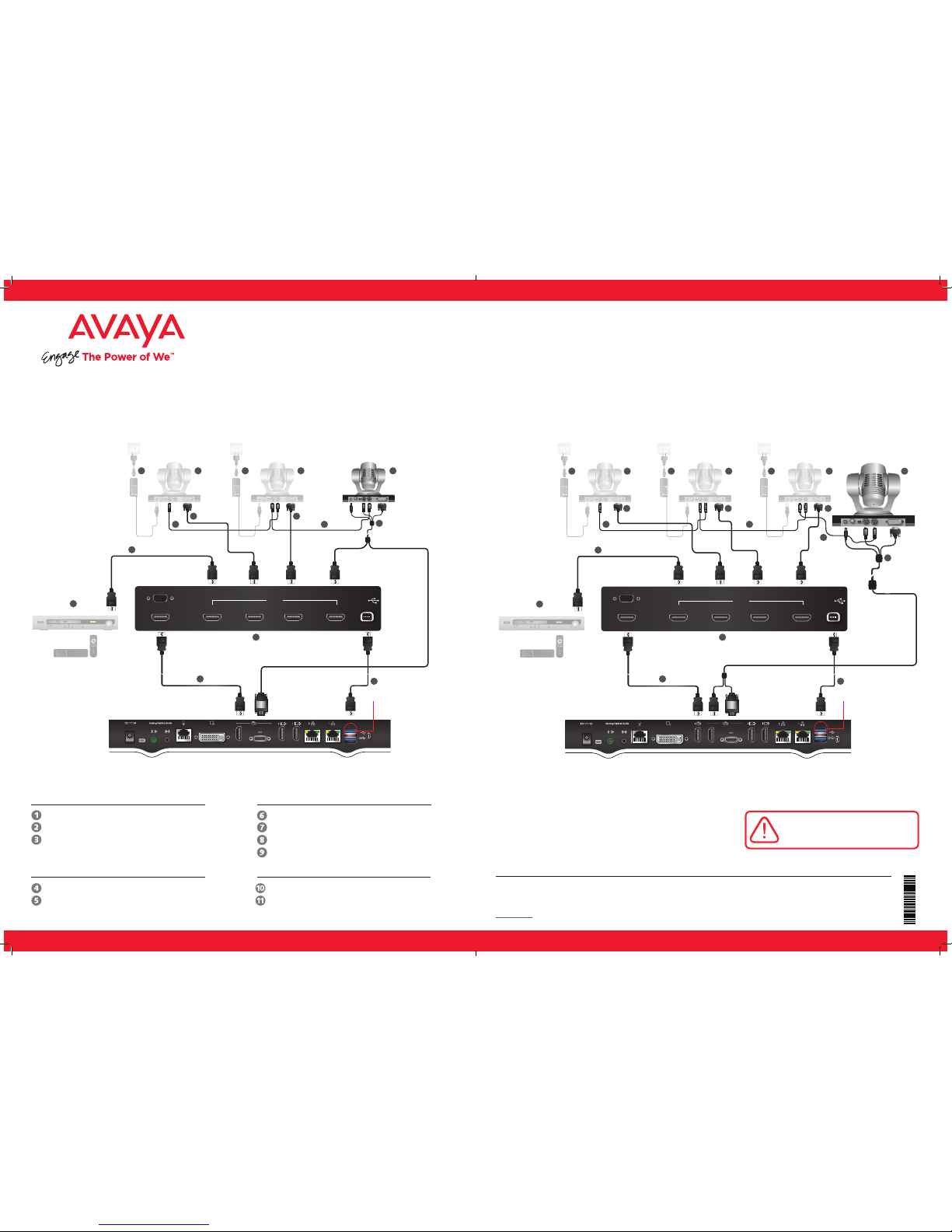
Sett ing Up th is Device
Connect the cables as detailed in the diagram overleaf, then follow the steps below to complete
the setup of the Avaya Scopia XT Camera Switch. For details on how to use the system after
setup, see the User Guide for Avaya Scopia XT Series or the Quick Start Guide for Avaya Scopia
XT Series.
CAUTION: Make sure all units are
switched off whenever connecting
or disconnecting devices.
Avaya Scopia XT7000
Codec Unit
Avaya Scopia XT5000
Codec Unit
Attach the two connectors on the other end of the camera cable:
2. The connector for power and serial control to the horizontal
socket on the XT Codec Unit.
1. On XT5000 Series, connect the
HDMI connector to the HDMI
socket labeled 1 on the Scopia
XT Camera Switch.
On XT7000 Series, connect the
first camera directlyto the HDMI1
port of the codec, as in single
camera setup.
1. Switch on the Scopia XT5000 or
XT7000 unit, the cameras and the
XT Camera Switch.
2. Set Configure > General > Show
Advanced Settings to Yes
3. Set Configure > Advanced > I/O
Connections > Cameras >
General > XT Camera Switch
detect mode = Yes.
(default PIN for Advanced configuration is 1234)
Connecting the first camera
Insert the three connectors of the
camera cable (3 connectors on one side,
2 connectors on the other side) to the
sockets on the back of the camera:
1. The DVI connector to the DVI socket.
2. The 8-pin connector to the
IN RS232C socket.
3. The power connector to the
DC IN 12V socket.
1. Setup each camera in the GUI
section
Configure > Advanced > I/O
Connections > Cameras
as explained in the “Deployment
Guide for XT Series”.
If required, repeat the above step for a third or fourth camera.
Check that the SYSTEM SELECT switch on the back panel of each
camera is set to 7:
DC IN 12V IN RS-232C OUT DVI
IR SELECT
1 2 3
1
2
3
4
5
6
7
8
9
SYSTEM
SELECT
XT Camera Switch
Connected to XT5000
1
1
XT Camera Switch
Connected to XT7000
2
2
Step 7.
Connect the second camera as follows:
1. Connect the 10-meter VISCA Control cable supplied with the
camera kit:
a. Attach one end of the VISCA control cable to the
IN RS-232C connector on the second camera.
b. Attach the other end to the OUT RS-232C
connector on the first camera.
2. Connect the DVI-HDMI cable as follows:
a. Attach the DVI connector to the DVI
socket on the second camera.
b. On XT5000, Attach the HDMI connector to the HDMI socket
labeled 2 on the Scopia XT Camera Switch.
On XT7000, Attach the HDMI connector to the HDMI socket
labeled 1 on the Scopia XT Camera Switch.
3. Connect one end of the power supply cable to the DC IN 12V
connector on the camera, and the other end into one of the
power sockets on the wall.
Place the Avaya Scopia XT Camera Switch on a horizontal surface
close to the XT Codec Unit. Maximum supplied cable length is
40cm (0.13ft).
1. Connect one end of the HDMI cable to the OUTPUT socket on
the Scopia XT Camera Switch
- On the XT5000 Codec Unit, connect the other
end to the available HDMI input.
- On XT7000 Codec Unit, connect the other
end to the HDMI2 input.
2. Connect one end of the USB cable to the USB socket on the
Avaya Scopia XT Camera Switch and the other end to the upper
USB connector on the XT Codec Unit.
Avaya Access ories In cluded
in Avaya Scopia XT5000/XT7000 box:
Avaya Scopia XT Camera Switch
Quick Hardware Setup
CAUTION: Make sure all units are
switched off whenever connecting
or disconnecting devices.
* All cables needed for video, power and control are
available separately when purchasing optional camera
(Premium or Advanced).
** Note: The Codec Unit is HDCP compliant, but
media will not be displayed for legal reasons.
*** If multiple cameras are cascaded using VISCA daisy chain, all must be the
same model (all Premium Cameras or all Advanced Cameras). Cascading different
camera models with VISCA daisy chain may yield wrong camera behavior.
Package Content:
Avaya Opti onal – No t Inclu ded Acces sories *:
Non -Avaya :
Optional Camera
VISCA cross cable
DVI – HDMI Cable
Power supply
Avaya Scopia XT Camera switch
Second Camera First CameraThird Camera
DVD/Blu-ray Player
Media Player
Fourth Camera
3
22
6 4
5
7
66 999
10
1234
DC IN 12V IN RS-232C OUT DVI
IR SELECT
1 2 3
1
2
3
4
5
6
7
8
9
SYSTEM
SELECT
DC IN 12V IN RS-232C OUT DVI
IR SELECT
1 2 3
1
2
3
4
5
6
7
8
9
SYSTEM
SELECT
DC IN 12V IN RS-232C OUT DVI
IR SELECT
1 2 3
1
2
3
4
5
6
7
8
9
SYSTEM
SELECT
CAUTION: the mains
cable is used as a
disconnecting device,
use therefore an easily
accessible outlet
located near the
device for the power
supply connection.
Never remove the
mains plug while the
device is connected.
1
Avaya Scopia XT Camera switch
1
RS-232
OUTPUT
INPUT
CAUTION: the mains
cable is used as a
disconnecting device,
use therefore an easily
accessible outlet
located near the
device for the power
supply connection.
Never remove the
mains plug while the
device is connected.
CAUTION: the mains
cable is used as a
disconnecting device,
use therefore an easily
accessible outlet
located near the
device for the power
supply connection.
Never remove the
mains plug while the
device is connected.
11
connect cable 2 to USB2
(upper USB connector)
connect cable 2 to USB2
(upper USB connector)
DC IN 12V IN RS-232C OUT DVI
IR SELECT
1 2 3
1
2
3
4
5
6
7
8
9
SYSTEM
SELECT
First CameraSecond Camera
DVD/Blu-ray Player
Media Player
Third Camera
3
4699
8
88 8
8
7 7 77
10
6
1234
DC IN 12V IN RS-232C OUT DVI
IR SELECT
1 2 3
1
2
3
4
5
6
7
8
9
SYSTEM
SELECT
DC IN 12V IN RS-232C OUT DVI
IR SELECT
1 2 3
1
2
3
4
5
6
7
8
9
SYSTEM
SELECT
CAUTION: the mains
cable is used as a
disconnecting device,
use therefore an easily
accessible outlet
located near the
device for the power
supply connection.
Never remove the
mains plug while the
device is connected.
RS-232
OUTPUT
INPUT
CAUTION: the mains
cable is used as a
disconnecting device,
use therefore an easily
accessible outlet
located near the
device for the power
supply connection.
Never remove the
mains plug while the
device is connected.
11
5
DC IN 12V IN RS-232C OUT DVI
IR SELECT
1 2 3
1
2
3
4
5
6
7
8
9
SYSTEM
SELECT
Avaya Scopia XT7000 Codec UnitAvaya Scopia XT5000 Codec Unit
XT Camera Switch unit
USB-USB cable
HDMI-HDMI Cable
First Camera
Triple Cable
© 2000-2015 Avaya Inc. All intellectual property rights in this publication are owned by Avaya Inc. and are protected by United States copyright laws, other applicable copyright laws and international treaty provisions. Avaya Inc. retains all
rights not expressly granted.All product and company names herein may be trademarks of their registered owners. This publication is Avaya Inc. Confidential & Proprietary. Use pursuant to your signed agreement or Avaya policy. No part of this
publication may be reproduced in any form whatsoever or used to make any derivative work without prior written approval by Avaya Inc. No representation of warranties for fitness for any purpose other than what is specifically mentioned in this
guide is made either by Avaya Inc. or its agents. Avaya Inc. reserves the right to revise this publication and make changes without obligation to notify any person of such revisions or changes. Avaya Inc may make improvements or changes in the
product(s) and/or the program(s) described in this documentation at any time. If there is any software on removable media described in this publication, it is furnished under a license agreement included with the product as a separate document.
If you are unable to locate a copy, please contact Avaya Inc and a copy will be provided to you. Unless otherwise indicated, Avaya registered trademarks are registered in the United States and other territories. All registered trademarks recognized.
For further information contact Avaya or your local distributor or reseller.
Quick Setup Guide for Avaya Scopia® XT Camera Switch Version 8.3, March, 2015.
http://www.avaya.com
Media player or Blu-ray device**
HDMI-HDMI cable.
rev. A02P/N 62111-02025
 Loading...