

Page 1
Avaya Scopia® XT5000
Package Content:
• Avaya Scopia XT5000 Codec Unit
• Avaya Scopia XT Premium Camera
• Avaya Scopia XT 3-ways Microphone POD
• Avaya Scopia XT Remote Control Unit
• First camera cable: 2.5m triple camera cable,
including power, VISCA and DVI-D/HDMI
• DVI-I to VGA converter
• Cable LAN 4mt
• Cable HDMI M/M, 2.5M
• Power Supply and power cable
• 3-ways Microphone POD cable
• Remote Control Batteries
Step 1. System Installation and Activation
1. Connect all cables to the Avaya Scopia XT5000 Codec Unit (see
overleaf). Power supply must be connected after all other connections
have been established.
2. Turn on the TV monitors. Monitor on HDMI1 is mandatory, monitor HDMI2
is optional.
3. Make sure the remote control has batteries installed.
4. Verify that the LED on the front panel of the Codec Unit is turned on.
5. If the codec unit does not turn on automatically, press the
button on
the remote control.
6. The graphical menu appears on the monitors.
Step 2. Product Registration
1. Open the envelope that came with the XT5000.
2. Locate the serial number and product key.
3. On a computer, open a browser and navigate to
http://licensing.radvision.com.
4. Complete the online registration form and enter the serial number and
product key. The web registration form returns a license key.
5. Write down the license key and keep it in a safe place for future use.
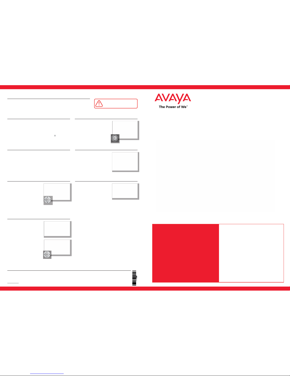
Step 3. Countr y and Langu age of In terfac e
1. The System Name field displays the
name of this Codec Unit as displayed in a
videoconference,
for example:
• Hong Kong, or
• 9th Floor Conf Rm
2. Use the remote control keypad to type
the name. Press OK to toggle letters or
numbers and lower/upper case.
3. Select the Country and preferred
Language.
4. Then select Next.
Step 4 . Graph ics and Image Se tup
If all the sides of the triangles
1 and 2 are visible on your monitor,
select next.
Step 5. Network Settings
1. Enter your network settings. For questions
about this information, consult your
system administrator.
2. Then select Next.
Step 6. Gatekeeper Settings
1. Enter your Gatekeeper settings
and your E.164 number. For questions
about this information, consult your
system administrator.
2. 2. Then select Done.
Step 7. Moving the Camera
1. On the general screen, navigate to Control
Camera using the arrow keys and press OK.
2. Use the arrow keys to move the camera to
the preferred position.
3. Repeat the procedure if you have a second
camera installed.
4. Press Back when done.
Your Scopia XT5000 sets the
standard for an exceptional
conferencing experience. Unique
simultaneous HD 1080p/60fps for
live video and content and CDquality, 20 kHz audio deliver an
outstanding experience. H.264 High
Profile provides ultimate bandwidth
efficiency and H.264 Scalable Video
Coding (SVC) offers high network
error resiliency.
Quick Setup Guide
Sett ing Up th is Device
CAUTION: Make sure all units are
switched off whenever connecting
or disconnecting devices.
Connect the cables as detailed in the diagram overleaf, then follow the steps below to complete
the setup of the Avaya Scopia XT5000. For details on how to use the system after setup, see the
User Guide for Avaya Scopia XT5000 or the Quick Start Guide for Avaya Scopia XT5000.
1. Otherwise, press 1 to adjust the position
of the top left corner.
2. Use the arrow keys to move the selected
triangle until it is fully visible on your
monitor.
Press OK when done.
3. Press 2 to adjust the position of the
bottom right corner.
4. Repeat the procedure using the arrows.
5. Press OK and Next when done.
© 2000-2014 Avaya Inc. All intellectual property rights in this publication are owned by Avaya Inc. and are protected by United States copyright laws, other applicable copyright laws and international treaty provisions. Avaya Inc. retains all
rights not expressly granted.All product and company names herein may be trademarks of their registered owners. This publication is Avaya Inc. Confidential & Proprietary. Use pursuant to your signed agreement or Avaya policy. No part of this
publication may be reproduced in any form whatsoever or used to make any derivative work without prior written approval by Avaya Inc. No representation of warranties for fitness for any purpose other than what is specifically mentioned in this
guide is made either by Avaya Inc. or its agents. Avaya Inc. reserves the right to revise this publication and make changes without obligation to notify any person of such revisions or changes. Avaya Inc may make improvements or changes in the
product(s) and/or the program(s) described in this documentation at any time. If there is any software on removable media described in this publication, it is furnished under a license agreement included with the product as a separate document.
If you are unable to locate a copy, please contact Avaya Inc and a copy will be provided to you. Unless otherwise indicated, Avaya registered trademarks are registered in the United States and other territories. All registered trademarks recognized.
For further information contact Avaya or your local distributor or reseller.
Quick Setup Guide for Avaya Scopia® XT 5000 Version 8.3, March, 2014.
http://www.avaya.com
rev. A01P/N 62111-02010
Page 2
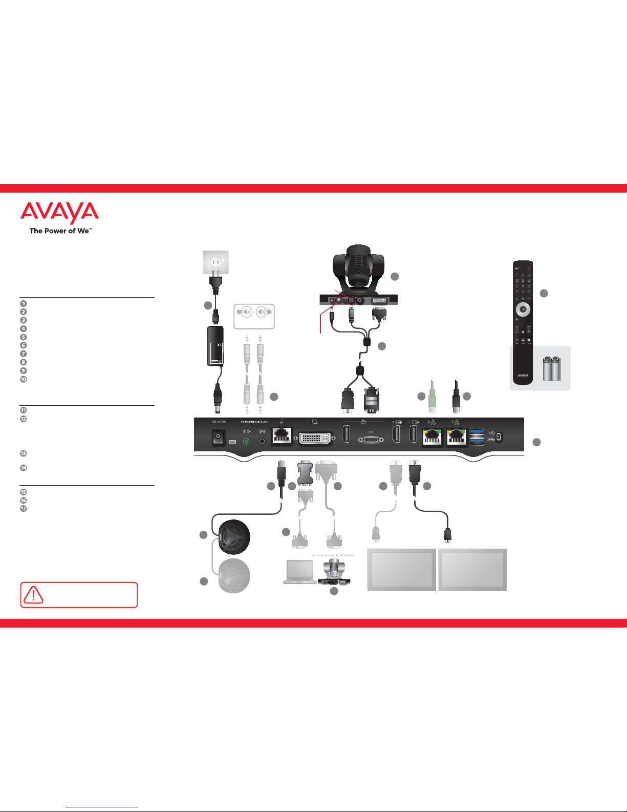
Avaya Scopia XT5000
Quick Hardware Setup
CAUTION: Make sure all units are
switched off whenever connecting
or disconnecting devices.
Package Content:
Codec Unit
Avaya Scopia XT Premium Camera
3-way Microphone POD
Remote Control Unit and Batteries
First camera cable
HDMI Cable
3-way Microphone POD cable
Ethernet Cable for LAN, 4m
Power Supply and Power Cable
DVI-I to VGA converter for PCs with VGA output only
DVI to DVI Cable
Audio Cable. Both sockets on the unit
are dual purpose. They accept either
an analog 3.5mm MiniJack cable or
an optical Toslink cable with a Toslink
mini-plug adapter. Optical digital audio
format is S/PDIF
Optional Premium Camera to be
connected to DVI input
Optional 2nd 3-way microphone POD
HDMI Cable for Mon2
Ethernet Cable for LAN
VGA cable
Avaya Optional –
Not Inc luded Accessor ies
Non -Avaya
DC IN 12V IN RS-232C OUT DVI
IR SELECT
1 2 3
1
2
3
4
5
6
7
8
9
SYSTEM
SELECT
Premium Camera
Make sure to
connect the
cable into the IN
connector.
4
16
15
8
5
2
Analog or digital
media device
Remote
Control
Batteries
9
1
6
7
14
3
Avaya Scopia
XT5000 Codec Unit
Please set the system
selector on the back
of the camera to 7.
12
17
10
11
DC IN 12V IN RS-232C OUT DVI
IR SELECT
1 2 3
1
2
3
4
5
6
7
8
9
SYSTEM
SELECT
13
Optional Premium Camera
CAUTION: the mains
cable is used as a
disconnecting device,
use therefore an easily
accessible outlet
located near the
device for the power
supply connection.
Never remove the
mains plug while the
device is connected.
 Loading...