

Page 1
Avaya Scopia® XT Series
Deployment Guide
Release 8.3.2
For Solution 8.3
April 2015
Page 2

Page 3

©
2015 Avaya Inc.
All Rights Reserved.
Notice
While reasonable efforts have been made to ensure that the
information in this document is complete and accurate at the time of
printing, Avaya assumes no liability for any errors. Avaya reserves
the right to make changes and corrections to the information in this
document without the obligation to notify any person or organization
of such changes.
Documentation disclaimer
“Documentation” means information published by Avaya in varying
mediums which may include product information, operating
instructions and performance specifications that Avaya may generally
make available to users of its products and Hosted Services.
Documentation does not include marketing materials. Avaya shall not
be responsible for any modifications, additions, or deletions to the
original published version of documentation unless such
modifications, additions, or deletions were performed by Avaya. End
User agrees to indemnify and hold harmless Avaya, Avaya's agents,
servants and employees against all claims, lawsuits, demands and
judgments arising out of, or in connection with, subsequent
modifications, additions or deletions to this documentation, to the
extent made by End User.
Link disclaimer
Avaya is not responsible for the contents or reliability of any linked
websites referenced within this site or documentation provided by
Avaya. Avaya is not responsible for the accuracy of any information,
statement or content provided on these sites and does not
necessarily endorse the products, services, or information described
or offered within them. Avaya does not guarantee that these links will
work all the time and has no control over the availability of the linked
pages.
Warranty
Avaya provides a limited warranty on Avaya hardware and software.
Refer to your sales agreement to establish the terms of the limited
warranty. In addition, Avaya’s standard warranty language, as well as
information regarding support for this product while under warranty is
available to Avaya customers and other parties through the Avaya
Support website:
http://support.avaya.com or such successor site as
designated by Avaya. Please note that if You acquired the product(s)
from an authorized Avaya Channel Partner outside of the United
States and Canada, the warranty is provided to You by said Avaya
Channel Partner and not by Avaya.
“Hosted Service” means a hosted service subscription that You
acquire from either Avaya or an authorized Avaya Channel Partner
(as applicable) and which is described further in Hosted SAS or other
service description documentation regarding the applicable hosted
service. If You purchase a Hosted Service subscription, the foregoing
limited warranty may not apply but You may be entitled to support
services in connection with the Hosted Service as described further
in your service description documents for the applicable Hosted
Service. Contact Avaya or Avaya Channel Partner (as applicable) for
more information.
Hosted Service
THE FOLLOWING APPLIES IF YOU PURCHASE A HOSTED
SERVICE SUBSCRIPTION FROM AVAYA OR AN AVAYA
CHANNEL PARTNER (AS APPLICABLE), THE TERMS OF USE
FOR HOSTED SERVICES ARE AVAILABLE ON THE AVAYA
WEBSITE,
HTTP://SUPPORT.AVAYA.COM/LICENSEINFO UNDER
THE LINK “Avaya Terms of Use for Hosted Services” OR SUCH
SUCCESSOR SITE AS DESIGNATED BY AVAYA, AND ARE
APPLICABLE TO ANYONE WHO ACCESSES OR USES THE
HOSTED SERVICE. BY ACCESSING OR USING THE HOSTED
SERVICE, OR AUTHORIZING OTHERS TO DO SO, YOU, ON
BEHALF OF YOURSELF AND THE ENTITY FOR WHOM YOU ARE
DOING SO (HEREINAFTER REFERRED TO INTERCHANGEABLY
AS “YOU” AND “END USER”), AGREE TO THE TERMS OF USE. IF
YOU ARE ACCEPTING THE TERMS OF USE ON BEHALF A
COMPANY OR OTHER LEGAL ENTITY, YOU REPRESENT THAT
YOU HAVE THE AUTHORITY TO BIND SUCH ENTITY TO THESE
TERMS OF USE. IF YOU DO NOT HAVE SUCH AUTHORITY, OR
IF YOU DO NOT WISH TO ACCEPT THESE TERMS OF USE, YOU
MUST NOT ACCESS OR USE THE HOSTED SERVICE OR
AUTHORIZE ANYONE TO ACCESS OR USE THE HOSTED
SERVICE. YOUR USE OF THE HOSTED SERVICE SHALL BE
LIMITED BY THE NUMBER AND TYPE OF LICENSES
PURCHASED UNDER YOUR CONTRACT FOR THE HOSTED
SERVICE, PROVIDED, HOWEVER, THAT FOR CERTAIN HOSTED
SERVICES IF APPLICABLE, YOU MAY HAVE THE OPPORTUNITY
TO USE FLEX LICENSES, WHICH WILL BE INVOICED
ACCORDING TO ACTUAL USAGE ABOVE THE CONTRACT
LICENSE LEVEL. CONTACT AVAYA OR AVAYA’S CHANNEL
PARTNER FOR MORE INFORMATION ABOUT THE LICENSES
FOR THE APPLICABLE HOSTED SERVICE, THE AVAILABILITY
OF ANY FLEX LICENSES (IF APPLICABLE), PRICING AND
BILLING INFORMATION, AND OTHER IMPORTANT
INFORMATION REGARDING THE HOSTED SERVICE.
Licenses
THE SOFTWARE LICENSE TERMS AVAILABLE ON THE AVAYA
WEBSITE,
HTTP://SUPPORT.AVAYA.COM/LICENSEINFO OR
SUCH SUCCESSOR SITE AS DESIGNATED BY AVAYA, ARE
APPLICABLE TO ANYONE WHO DOWNLOADS, USES AND/OR
INSTALLS AVAYA SOFTWARE, PURCHASED FROM AVAYA INC.,
ANY AVAYA AFFILIATE, OR AN AVAYA CHANNEL PARTNER (AS
APPLICABLE) UNDER A COMMERCIAL AGREEMENT WITH
AVAYA OR AN AVAYA CHANNEL PARTNER. UNLESS
OTHERWISE AGREED TO BY AVAYA IN WRITING, AVAYA DOES
NOT EXTEND THIS LICENSE IF THE SOFTWARE WAS
OBTAINED FROM ANYONE OTHER THAN AVAYA, AN AVAYA
AFFILIATE OR AN AVAYA CHANNEL PARTNER; AVAYA
RESERVES THE RIGHT TO TAKE LEGAL ACTION AGAINST YOU
AND ANYONE ELSE USING OR SELLING THE SOFTWARE
WITHOUT A LICENSE. BY INSTALLING, DOWNLOADING OR
USING THE SOFTWARE, OR AUTHORIZING OTHERS TO DO SO,
YOU, ON BEHALF OF YOURSELF AND THE ENTITY FOR WHOM
YOU ARE INSTALLING, DOWNLOADING OR USING THE
SOFTWARE (HEREINAFTER REFERRED TO
INTERCHANGEABLY AS “YOU” AND “END USER”), AGREE TO
THESE TERMS AND CONDITIONS AND CREATE A BINDING
CONTRACT BETWEEN YOU AND AVAYA INC. OR THE
APPLICABLE AVAYA AFFILIATE (“AVAYA”).
Avaya grants You a license within the scope of the license types
described below, with the exception of Heritage Nortel Software, for
which the scope of the license is detailed below. Where the order
documentation does not expressly identify a license type, the
applicable license will be a Designated System License. The
applicable number of licenses and units of capacity for which the
license is granted will be one (1), unless a different number of
licenses or units of capacity is specified in the documentation or other
materials available to You. “Software” means computer programs in
object code, provided by Avaya or an Avaya Channel Partner,
whether as stand-alone products, pre-installed on hardware products,
and any upgrades, updates, patches, bug fixes, or modified versions
thereto. “Designated Processor” means a single stand-alone
computing device. “Server” means a Designated Processor that
hosts a software application to be accessed by multiple users.
“Instance” means a single copy of the Software executing at a
particular time: (i) on one physical machine; or (ii) on one deployed
software virtual machine (“VM”) or similar deployment.
License types
Designated System(s) License (DS). End User may install and use
each copy or an Instance of the Software only on a number of
Designated Processors up to the number indicated in the order.
Avaya may require the Designated Processor(s) to be identified in
the order by type, serial number, feature key, Instance, location or
other specific designation, or to be provided by End User to Avaya
through electronic means established by Avaya specifically for this
purpose.
Concurrent User License (CU). End User may install and use the
Software on multiple Designated Processors or one or more Servers,
so long as only the licensed number of Units are accessing and using
the Software at any given time. A “Unit” means the unit on which
Avaya, at its sole discretion, bases the pricing of its licenses and can
be, without limitation, an agent, port or user, an e-mail or voice mail
account in the name of a person or corporate function (e.g.,
webmaster or helpdesk), or a directory entry in the administrative
database utilized by the Software that permits one user to interface
Page 4

with the Software. Units may be linked to a specific, identified Server
or an Instance of the Software.
Database License (DL). End User may install and use each copy or
an Instance of the Software on one Server or on multiple Servers
provided that each of the Servers on which the Software is installed
communicates with no more than one Instance of the same
database.
CPU License (CP). End User may install and use each copy or
Instance of the Software on a number of Servers up to the number
indicated in the order provided that the performance capacity of the
Server(s) does not exceed the performance capacity specified for the
Software. End User may not re-install or operate the Software on
Server(s) with a larger performance capacity without Avaya’s prior
consent and payment of an upgrade fee.
Named User License (NU). You may: (i) install and use the Software
on a single Designated Processor or Server per authorized Named
User (defined below); or (ii) install and use the Software on a Server
so long as only authorized Named Users access and use the
Software. “Named User”, means a user or device that has been
expressly authorized by Avaya to access and use the Software. At
Avaya’s sole discretion, a “Named User” may be, without limitation,
designated by name, corporate function (e.g., webmaster or
helpdesk), an e-mail or voice mail account in the name of a person or
corporate function, or a directory entry in the administrative database
utilized by the Software that permits one user to interface with the
Software.
Shrinkwrap License (SR). You may install and use the Software in
accordance with the terms and conditions of the applicable license
agreements, such as “shrinkwrap” or “clickthrough” license
accompanying or applicable to the Software (“Shrinkwrap License”).
CPU License (CP). End User may install and use each copy or
Instance of the Software on a number of Servers up to the number
indicated in the order provided that the performance capacity of the
Server(s) does not exceed the performance capacity specified for the
Software. End User may not re-install or operate the Software on
Server(s) with a larger performance capacity without Avaya’s prior
consent and payment of an upgrade fee.
Named User License (NU). You may: (i) install and use the Software
on a single Designated Processor or Server per authorized Named
User (defined below); or (ii) install and use the Software on a Server
so long as only authorized Named Users access and use the
Software. “Named User”, means a user or device that has been
expressly authorized by Avaya to access and use the Software. At
Avaya’s sole discretion, a “Named User” may be, without limitation,
designated by name, corporate function (e.g., webmaster or
helpdesk), an e-mail or voice mail account in the name of a person or
corporate function, or a directory entry in the administrative database
utilized by the Software that permits one user to interface with the
Software.
Heritage Nortel Software
“Heritage Nortel Software” means the software that was acquired by
Avaya as part of its purchase of the Nortel Enterprise Solutions
Business in December 2009. The Heritage Nortel Software currently
available for license from Avaya is the software contained within the
list of Heritage Nortel Products located at
LicenseInfo under the link “Heritage Nortel Products” or such
successor site as designated by Avaya. For Heritage Nortel
Software, Avaya grants You a license to use Heritage Nortel
Software provided hereunder solely to the extent of the authorized
activation or authorized usage level, solely for the purpose specified
in the Documentation, and solely as embedded in, for execution on,
or for communication with Avaya equipment. Charges for Heritage
Nortel Software may be based on extent of activation or use
authorized as specified in an order or invoice.
Copyright
Except where expressly stated otherwise, no use should be made of
materials on this site, the Documentation, Software, Hosted Service,
or hardware provided by Avaya. All content on this site, the
documentation, Hosted Service, and the product provided by Avaya
including the selection, arrangement and design of the content is
owned either by Avaya or its licensors and is protected by copyright
and other intellectual property laws including the sui generis rights
relating to the protection of databases. You may not modify, copy,
http://support.avaya.com/
reproduce, republish, upload, post, transmit or distribute in any way
any content, in whole or in part, including any code and software
unless expressly authorized by Avaya. Unauthorized reproduction,
transmission, dissemination, storage, and or use without the express
written consent of Avaya can be a criminal, as well as a civil offense
under the applicable law.
Virtualization
Each product has its own ordering code and license types. Note that
each Instance of a product must be separately licensed and ordered.
For example, if the end user customer or Avaya Channel Partner
would like to install two Instances of the same type of products, then
two products of that type must be ordered.
Third Party Components
“Third Party Components” mean certain software programs or
portions thereof included in the Software or Hosted Service may
contain software (including open source software) distributed under
third party agreements (“Third Party Components”), which contain
terms regarding the rights to use certain portions of the Software
(“Third Party Terms”). As required, information regarding distributed
Linux OS source code (for those products that have distributed Linux
OS source code) and identifying the copyright holders of the Third
Party Components and the Third Party Terms that apply is available
in the products, Documentation or on Avaya’s website at:
support.avaya.com/Copyright or such successor site as designated
by Avaya. You agree to the Third Party Terms for any such Third
Party Components.
THIS PRODUCT IS LICENSED UNDER THE AVC PATENT
PORTFOLIO LICENSE FOR THE PERSONAL USE OF A
CONSUMER OR OTHER USES IN WHICH IT DOES NOT RECEIVE
REMUNERATION TO (i) ENCODE VIDEO IN COMPLIANCE WITH
THE AVC STANDARD (“AVC VIDEO”) AND/OR (ii) DECODE AVC
VIDEO THAT WAS ENCODED BY A CONSUMER ENGAGED IN A
PERSONAL ACTIVITY AND/OR WAS OBTAINED FROM A VIDEO
PROVIDER LICENSED TO PROVIDE AVC VIDEO. NO LICENSE IS
GRANTED OR SHALL BE IMPLIED FOR ANY OTHER USE.
ADDITIONAL INFORMATION MAY BE OBTAINED FROM MPEG
LA, L.L.C. SEE
Note to Service Provider
The product or Hosted Service may use Third Party Components
subject to Third Party Terms that do not allow hosting and require a
Service Provider to be independently licensed for such purpose. It is
your responsibility to obtain such licensing.
Preventing Toll Fraud
“Toll Fraud” is the unauthorized use of your telecommunications
system by an unauthorized party (for example, a person who is not a
corporate employee, agent, subcontractor, or is not working on your
company's behalf). Be aware that there can be a risk of Toll Fraud
associated with your system and that, if Toll Fraud occurs, it can
result in substantial additional charges for your telecommunications
services.
Avaya Toll Fraud intervention
If You suspect that You are being victimized by Toll Fraud and You
need technical assistance or support, call Technical Service Center
Toll Fraud Intervention Hotline at +1-800-643-2353 for the United
States and Canada. For additional support telephone numbers, see
the Avaya Support website:
successor site as designated by Avaya. Suspected security
vulnerabilities with Avaya products should be reported to Avaya by
sending mail to: [email protected].
Downloading Documentation
For the most current versions of Documentation, see the Avaya
Support website:
designated by Avaya.
Contact Avaya Support
See the Avaya Support website:
or Hosted Service notices and articles, or to report a problem with
your Avaya product or Hosted Service. For a list of support telephone
numbers and contact addresses, go to the Avaya Support website:
http://support.avaya.com (or such successor site as designated by
HTTP://WWW.MPEGLA.COM.
http://support.avaya.com or such
http://support.avaya.com, or such successor site as
http://support.avaya.com for product
http://
Page 5

Avaya), scroll to the bottom of the page, and select Contact Avaya
Support.
Trademarks
The trademarks, logos and service marks (“Marks”) displayed in this
site, the Documentation, Hosted Service(s), and product(s) provided
by Avaya are the registered or unregistered Marks of Avaya, its
affiliates, or other third parties. Users are not permitted to use such
Marks without prior written consent from Avaya or such third party
which may own the Mark. Nothing contained in this site, the
Documentation, Hosted Service(s) and product(s) should be
construed as granting, by implication, estoppel, or otherwise, any
license or right in and to the Marks without the express written
permission of Avaya or the applicable third party.
Avaya is a registered trademark of Avaya Inc.
All non-Avaya trademarks are the property of their respective owners.
Linux® is the registered trademark of Linus Torvalds in the U.S. and
other countries.
Page 6

Contents
Chapter 1: About the XT Series............................................................................................... 9
About the Models in the XT Series Product Line...................................................................... 10
Comparing Between XT Series Models................................................................................... 15
About the Built-In MCU.......................................................................................................... 17
Technical Specifications......................................................................................................... 18
Checking the Product Shipment.............................................................................................. 21
Chapter 2: Initial Workflow for Deploying the Avaya Scopia® XT Series.......................... 22
Chapter 3: Planning the Topology of the Avaya Scopia® XT Series Deployment............ 24
Topology for Avaya Scopia® XT Series as Endpoints............................................................... 24
Planning the Topology of Avaya Scopia® XT Series with Scopia® XT Desktop........................... 25
Planning NAT and Firewall Traversal with Avaya Scopia® XT Series......................................... 27
Supporting ISDN Connectivity................................................................................................ 29
Implementing External API Control......................................................................................... 30
Implementing Port Security for the Avaya Scopia® XT Series.................................................... 31
Opening Ports for the XT Series....................................................................................... 31
Configuring the TCP or UDP Port Range on the Avaya Scopia® XT Series.......................... 40
Chapter 4: Setting Up the XT Series Hardware.................................................................... 42
Planning the Optimal Room Setup.......................................................................................... 42
Connecting Avaya Scopia® XT Series to the Network............................................................... 46
Connecting Monitors to the XT Series..................................................................................... 47
Connecting Cameras or DVD players...................................................................................... 48
Connecting the PTZ Camera............................................................................................ 49
Connecting an Additional PTZ Camera Directly.................................................................. 51
Connecting Multiple HDMI Devices or Cameras via the Scopia® XT Camera Switch............. 54
Connecting a DVD or Blu-ray Player or Other Analog Video Equipment............................... 58
Connecting Microphones and Speakers to the XT Series.......................................................... 59
Choosing a Microphone for Your XT Series....................................................................... 59
Connecting a Microphone to the XT Series........................................................................ 62
Connecting Headphones or an Amplifier with Loudspeakers............................................... 64
Connecting a Computer to the XT Series................................................................................. 65
Chapter 5: Controlling the XT Series.................................................................................... 68
Accessing the XT Series Local Menu...................................................................................... 68
About the XT Remote Control Unit.......................................................................................... 70
Pairing an XT Remote Control Unit................................................................................... 72
Navigating Menus with the Keyboard and Mouse..................................................................... 73
Accessing XT Series Web Interface........................................................................................ 75
Managing Avaya Scopia® XT Series from Scopia® Management.............................................. 76
Chapter 6: Initial Configuration of the XT Series................................................................. 78
Activating the XT Series and its Optional Features................................................................... 78
6 Avaya Scopia
®
XT Series Deployment Guide April 2015
Comments? [email protected]
Page 7

Contents
Configuring Basic Settings with the Quick Setup Wizard........................................................... 83
Setting the System Name, Language, and Call Method...................................................... 84
Adjusting the Image Position............................................................................................ 86
Configuring Basic Network Settings.................................................................................. 87
Configuring Basic Gatekeeper Settings............................................................................. 89
Configuring Basic SIP Settings......................................................................................... 90
Installing Scopia® XT Control to Use Keyboard and Mouse (Scopia® XT Executive)............. 91
Setting Date and Time..................................................................................................... 93
Setting the Time Zone..................................................................................................... 94
Configuring the Screen Saver to Start Automatically........................................................... 95
Configuring Monitors.............................................................................................................. 96
Configuring Cameras........................................................................................................... 100
Configuring Microphones..................................................................................................... 104
Registering the XT Series to a SIP Server ............................................................................ 107
Chapter 7: Advanced Configuration of the XT Series....................................................... 112
Enabling Advanced Maintenance on the XT Series................................................................ 112
Configuring Advanced System Name Settings....................................................................... 114
Configuring Advanced Network Settings................................................................................ 116
Configuring Advanced IP Address Settings...................................................................... 116
Configuring Advanced Network Connectivity.................................................................... 118
Configuring NAT and Firewall Traversal.......................................................................... 121
Defining QoS Priority of Types of Network Traffic............................................................. 122
Configuring Advanced Gatekeeper Settings.................................................................... 124
Setting Call Bandwidth in XT Series...................................................................................... 127
Setting a Time Limit for Videoconferences............................................................................. 130
Configuring Advanced Sound (Audio Output) Settings............................................................ 131
Configuring Advanced Regional Audio and Video Settings...................................................... 136
Configuring Advanced Echo Cancellation on External Microphones......................................... 137
Configuring XT Series to use LDAP Directory........................................................................ 139
Configuring Advanced DTMF Settings................................................................................... 142
Enabling and Configuring Recording..................................................................................... 144
Saving PTZ Camera Positions.............................................................................................. 147
Remotely Controlling the XT Series with AT Commands......................................................... 149
Sending Status with SNMP.................................................................................................. 151
Updating the XT Series........................................................................................................ 153
Upgrading the Software Using a PC................................................................................ 153
Upgrading the Avaya Scopia® XT Series Software Using a USB Drive.............................. 155
Chapter 8: Securing your XT Series.................................................................................... 156
Setting PIN Codes for the XT Series..................................................................................... 156
Securing Web Access to the XT Series................................................................................. 157
Enabling and Securing Remote Upgrades............................................................................. 159
Securing Connections to the XT Series Using TLS................................................................. 160
Generating and Uploading a Certificate Signing Request for XT Series.............................. 162
April 2015 Avaya Scopia® XT Series Deployment Guide 7
Comments? [email protected]
Page 8

Contents
Backing Up and Restoring XT Series Certificates............................................................. 165
Deleting XT Series Certificates....................................................................................... 166
Enabling the TLS Connection in XT Series...................................................................... 167
Enabling Encryption for Videoconferences....................................................................... 169
Chapter 9: Troubleshooting the Avaya Scopia® XT Series.............................................. 172
Viewing System Information for Customer Support................................................................. 172
Retrieving XT Series Logs.................................................................................................... 175
Enabling System Logs and Remote Initialization.............................................................. 175
Retrieving Network Traffic Logs...................................................................................... 177
Retrieving System Logs................................................................................................. 178
Resolving Problems Connecting Calls................................................................................... 179
Resolving Audio Problems................................................................................................... 181
Cancelling the Echo on HDMI Monitors................................................................................. 183
Resolving Monitor Display Problems..................................................................................... 185
Improving Call Video Resolution........................................................................................... 187
Resolving Problems with Displaying Video............................................................................ 190
Resolving Lip Sync Problem................................................................................................. 191
Resolving Camera Issues.................................................................................................... 193
Resolving IP Address Problems............................................................................................ 195
Cannot Control with Keyboard and Mouse............................................................................. 196
Resolving Problems Viewing Computer Content.................................................................... 197
Resolving XT Remote Control Unit Problems......................................................................... 198
Resolving download problems.............................................................................................. 198
USB Software Upgrade Failure............................................................................................. 199
Restoring Default User Settings............................................................................................ 199
Glossary................................................................................................................................. 201
8 Avaya Scopia
®
XT Series Deployment Guide April 2015
Comments? [email protected]
Page 9
Chapter 1: About the XT Series
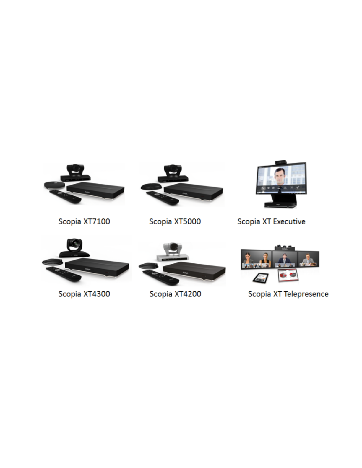
The Avaya Scopia® XT Series is a set of dedicated videoconferencing endpoints which incorporate
state-of-the-art video technology for high definition (HD) conferencing. You can also locally host
videoconferences with the built-in MCU on most XT Series models. The XT Series seamlessly
works with a wide variety of endpoints, including H.323, SIP, Scopia® Desktop Clients, Scopia
Mobile devices, and ISDN endpoints (via Scopia® 100 Gateway).
®
Figure 1: XT Series products
This section provides an overview of the general features and capabilities available in the XT Series:
• Excellent video quality, with resolutions of up to 1080p at an unprecedented 60 frames per
second (fps), depending on the model.
• Support for dual HD video streams, allowing PC presentations to be shared alongside video
from the camera in resolutions of up to 1080p at 60fps, depending on the model.
• Quickly and seamlessly share content on your computer with other endpoints.
• DVD-quality audio with up to 48 kHz sampling rate audio encoding capability, depending on the
model. The sampling rate is a measure of the accuracy of the audio when it is digitized. The XT
Series endpoints are shipped with different microphones depending on the model. You can add
dedicated Microphone Pods or additional analog microphones if required.
April 2015 Avaya Scopia® XT Series Deployment Guide 9
Comments? [email protected]
Page 10

About the XT Series
• High quality video and audio even with limited bandwidth or poor network conditions, by using
these compression methods (in addition to standard H.263 and H.264):
- H.264 Scalable Video Coding Technology (SVC) in point-to-point calls. SVC extends the H.
264 codec standard to dramatically increase error resiliency and video quality without the
need for higher bandwidth.
- H.264 High Profile is a standard for compressing video by up to 25% over the H.264
Baseline Profile, enabling high definition calls to be held over lower call speeds. It requires
both sides of the transmission (sending and receiving endpoints) to support this protocol.
- H.265 supersedes H.264 as a compression standard, allowing high quality calls with even
lower bandwidth consumption (XT7000 Series only).
- NetSense is a proprietary Scopia® Solution technology which optimizes the video quality
according to the available bandwidth to minimize packet loss. As the available bandwidth of
a connection varies depending on data traffic, NetSense's sophisticated algorithm
dynamically scans the video stream, and then reduces or improves the video resolution to
maximize quality with the available bandwidth.
• Ability to record videoconferences to a locally connected USB drive or the network (may
require license, depending on the model).
You can only record to the network if your Scopia® Solution includes a recording server, the XT
Series is managed by Scopia® Management, and the meeting is hosted by an external
Scopia® Elite MCU (or an older model).
• For an even better experience, Scopia® Control enables you to remotely control the XT Series
features using the intuitive touch interface of an Apple® iPad® (may require license, depending
on the model).
• Secure point-to-point video calls and videoconferences, via encrypted connections or using
TLS certificates. You can have up to three remote encrypted participants in a videoconference.
Important:
Using encryption is subject to local regulation. In some countries it is restricted or limited
for usage. For more information, consult your local reseller.
Related Links
About the Models in the XT Series Product Line on page 10
Comparing Between XT Series Models on page 15
About the Built-In MCU on page 17
Technical Specifications on page 18
Checking the Product Shipment on page 21
About the Models in the XT Series Product Line
The Avaya Scopia® XT Series is a set of dedicated videoconferencing endpoints which incorporate
state-of-the-art video technology for high definition (HD) conferencing. You can also locally host
10 Avaya Scopia
®
XT Series Deployment Guide April 2015
Comments? [email protected]
Page 11
About the Models in the XT Series Product Line
videoconferences with the built-in MCU on most XT Series models. The XT Series seamlessly
works with a wide variety of endpoints, including H.323, SIP, Scopia® Desktop Clients, Scopia
®
Mobile devices, and ISDN endpoints (via Scopia® 100 Gateway).
This section provides an overview of each model in the XT Series product line. To easily compare
the different Avaya Scopia® XT Series endpoints, see
Comparing Between XT Series Models on
page 15.
The Avaya Scopia® XT Series includes the following models:
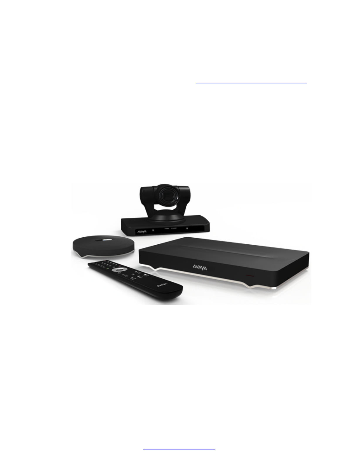
• Avaya Scopia® XT7000 Series
Designed for top performance and quality, the XT7000 Series offers excellent video quality
(1080p video at 60 frames per second) while saving on bandwidth costs. With the new H.265
video compression standard, you can have the same high quality video while consuming less
bandwidth (up to 50%, relative to endpoints with H.264 High Profile).
For unparalleled large room coverage, you can connect two PTZ cameras and two 3-way
Microphone Pods. The 3-way Microphone Pod provides superb signal-to-noise ratios, which
isolates speakers' voices over background noise and gives a crisp high quality sound.
Figure 2: Avaya Scopia® XT7000 Series
• Avaya Scopia® XT5000 Series
With HD video resolution of up to 1080p video at 60 frames per second (fps), the XT5000 sets
the standard for an exceptional videoconferencing experience, and is designed for easy setup
and control.
The 3-way Microphone Pod provides superb signal-to-noise ratios, which isolates speakers'
voices over background noise and gives a crisp high quality sound. You can also add a second
microphone for unparalleled large room coverage.
The XT5000 720 provides HD video resolution of 720p at 60 fps and 5x optical zoom, with the
option to upgrade to 1080p at 60fps and 10x optical zoom.
April 2015 Avaya Scopia® XT Series Deployment Guide 11
Comments? [email protected]
Page 12
About the XT Series
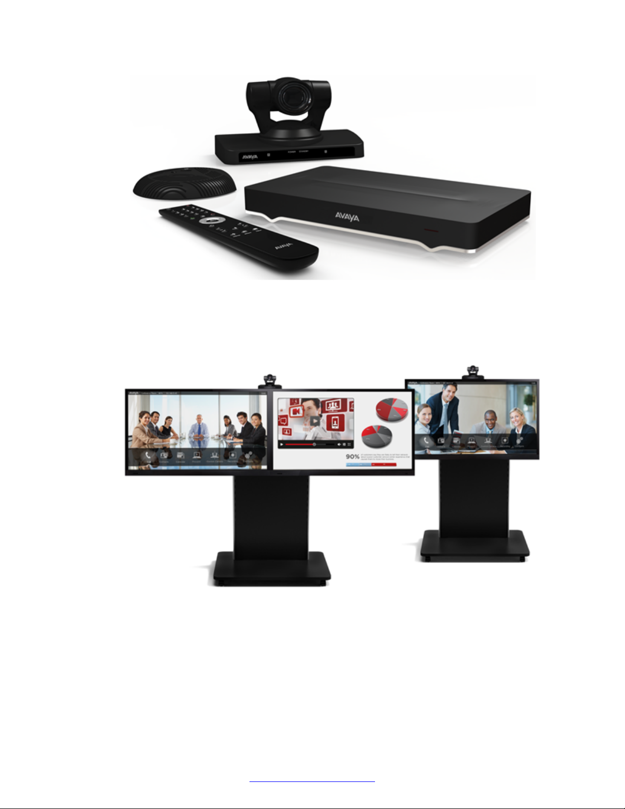
You can quickly convert a regular meeting room into a videoconferencing room by adding the
Scopia® XT Meeting Center Cart to the XT5000. The Scopia® XT Meeting Center Cart allows
you to mount up to two HD 1080p monitors on a mobile stand.
Figure 3: Avaya Scopia® XT5000 Series
• Avaya Scopia® XT4000 Series
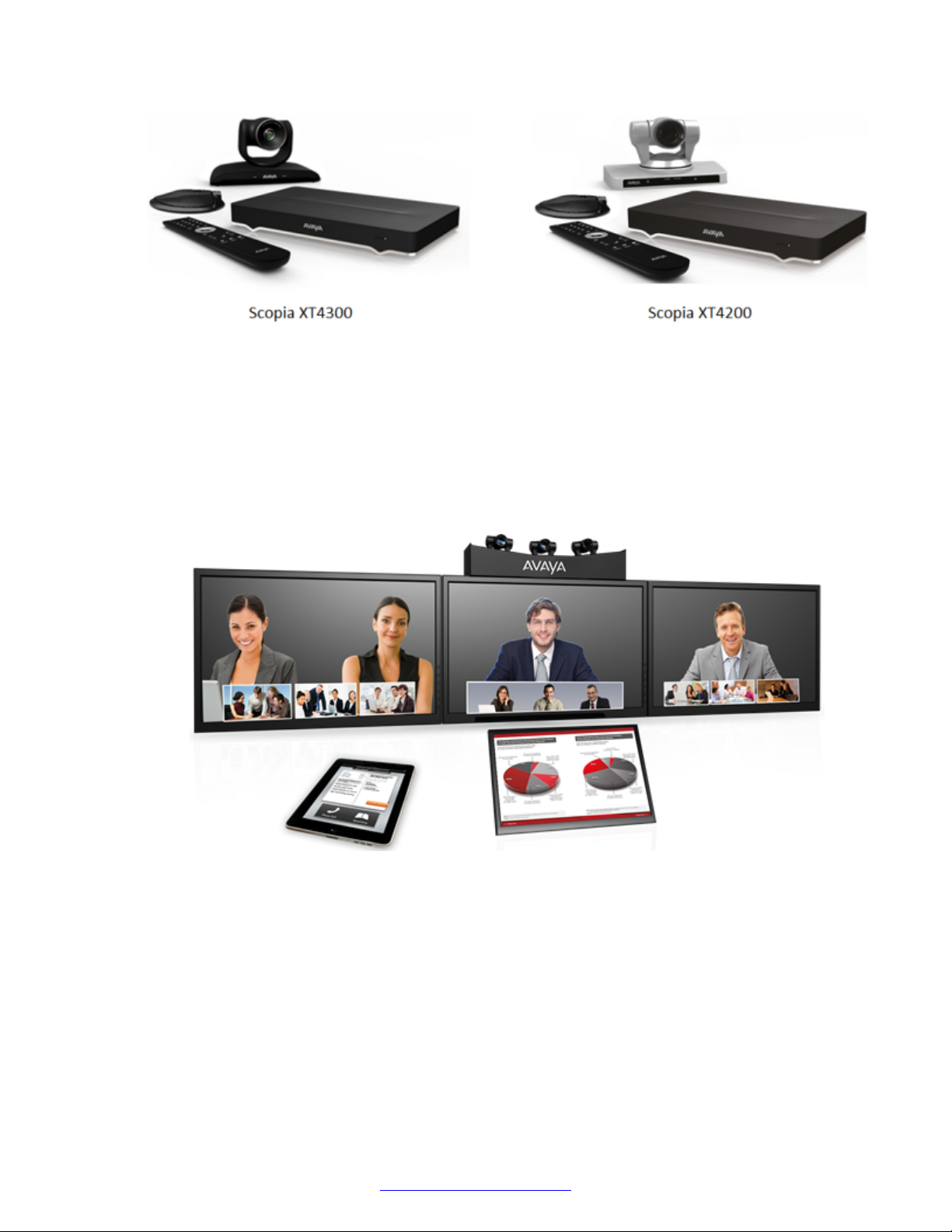
Experience cost-effective HD videoconferencing with the Avaya Scopia® XT4000 Series, which
was designed specifically for small meeting rooms. The Avaya Scopia® XT4300 offers HD
resolution of 1080p at 60 fps and 5x optical zoom, with the option to upgrade to 15x total zoom
(5x optical and 3x digital). The Avaya Scopia® XT4200 provides HD resolution of 720p at 60
fps and 5x optical zoom, with the option to upgrade to 40x zoom (10x optical and 4x digital).
12 Avaya Scopia
Figure 4: Scopia® XT Meeting Center Cart
®
XT Series Deployment Guide April 2015
Comments? [email protected]
Page 13
About the Models in the XT Series Product Line
Figure 5: Models in the Avaya Scopia® XT4000 Series
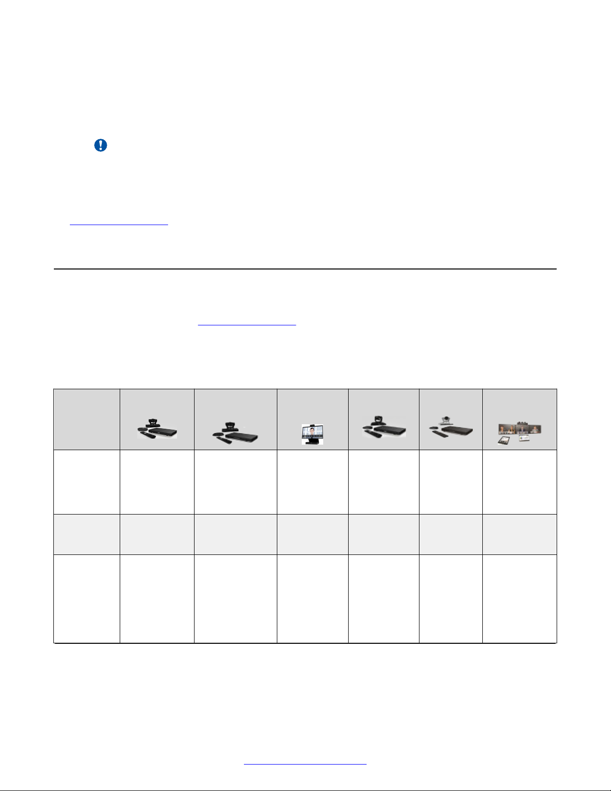
• Avaya Scopia® XT Telepresence
Experience the immersive feeling of telepresence using the Scopia® XT Telepresence
platform. The excellent video quality in each of the three cameras, combined with high-quality
audio, give the feeling of an in-person meeting.
Depending on the XT Codec Unit used in your XT Telepresence deployment, you can inherit
the features of the Avaya Scopia® XT5000.
Figure 6: Scopia® XT Telepresence
• Avaya Scopia® XT Executive
Designed as a professional personal endpoint, the Scopia® XT Executive is an all-in-one HD
videoconferencing desktop endpoint and PC monitor. The Scopia® XT Executive fully
integrates with your PC or Mac. Using a unique control application, you can place calls, join
videoconferences, and navigate the system menus with your computer's keyboard and mouse.
The XT Remote Control Unit can be used as well.
April 2015 Avaya Scopia® XT Series Deployment Guide 13
Comments? [email protected]
Page 14

About the XT Series
The Scopia® XT Executive has a built-in, high-quality HD camera with a maximum resolution of
1080p at 30 frames per second (fps) together with the display. To fit your videoconferencing
needs, you can also connect an optional XT Premium Camera with PTZ capability.
Figure 7: Scopia® XT Executive
The XT7000 Series, XT5000, XT4300 and Scopia® XT Executive can also locally host HD
continuous presence videoconferences with their built-in MCU. You can choose a license of up to 4
or 9 participants.
Important:
The Scopia® XT Executive and Avaya Scopia® XT4300 can host up to four participants.
Depending on your deployment and the model, you can locally host videoconferences with other
endpoints (including H.323, SIP, Scopia® XT Desktop clients, Scopia® Mobile, and ISDN endpoints,
if your deployment includes an ISDN gateway such as Scopia® 100 Gateway) without relying on an
external MCU. You can locally host videoconferences with the following editions:
• Avaya Scopia® XT Series MCU Edition
The Avaya Scopia® XT Series MCU Edition allows you to host videoconferences with standard
H.323, SIP, and ISDN (via Scopia® 100 Gateway) endpoints on your chosen XT Series model.
• Avaya Scopia® XT Series SMB Edition
14 Avaya Scopia
®
XT Series Deployment Guide April 2015
Comments? [email protected]
Page 15
Comparing Between XT Series Models
The Avaya Scopia® XT Series SMB Edition allows you to host videoconferences with a variety
of different endpoints on your chosen XT Series model: Scopia® XT Desktop clients, Scopia
Mobile clients, H.323, SIP, and ISDN (via Scopia® 100 Gateway) endpoints.
It includes the software of the Scopia® XT Desktop server which must be deployed in the DMZ.
Important:
If your license allows nine participants, you can include up to eight remote endpoints.
For more information on the SMB Solution deployment, see Avaya Scopia® Solution Guide.
Related Links
About the XT Series on page 9
Comparing Between XT Series Models
This section provides a comparison between the models of the Avaya Scopia® XT Series product
line. For an overview, see About the XT Series on page 9.
®
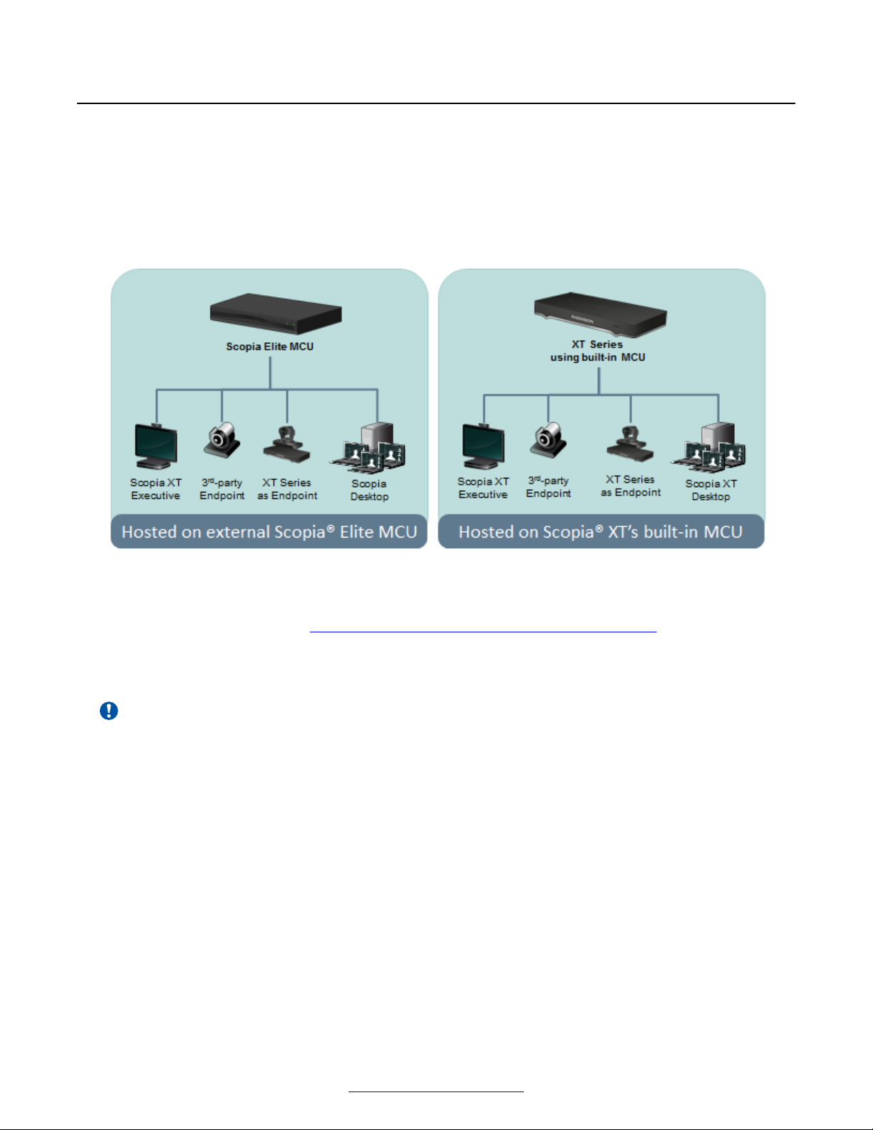
The following table summarizes the differences between each of the models in the XT Series.
Table 1: Differences in features for models in the XT Series
Feature XT7100 XT5000/
XT5000 720
Maximum
resolution
Hosting
with built-in
MCU
Camera PTZ camera
1080p 60fps 1080p 60fps
XT5000 720:
720p 60fps
(1080p optional)
Up to 9
participants
(optional)
3 camera
ports (6 with
Scopia® XT
Camera
Switch)
Up to 9
participants
(optional)
PTZ camera
2 camera ports
(5 with Scopia
XT Camera
Switch)
Scopia® XT
Executive
1080p at
30fps (built-in
camera) or
60fps (PTZ
camera)
Up to 4
participants
(optional)
Built-in USB
camera with
digital PTZ
®
only
(additional
PTZ camera
optional)
XT4300 XT4200 Scopia® XT
1080p 60fps 720p 60fps 1080p x3 at
Up to 4
participants
(optional)
PTZ camera
1 camera port
— —
PTZ
camera
1 camera
port
Table continues…
Telepresence
60fps
PTZ disabled
after
calibration
April 2015 Avaya Scopia® XT Series Deployment Guide 15
Comments? [email protected]
Page 16

About the XT Series
Feature XT7100 XT5000/
XT5000 720
Optical
zoom
10x 10x
XT5000 720: 5x
(10x optional)
Total zoom
(optical x
40x 40x (optional for
XT5000 720)
digital)
Bandwidth
efficiency
H.265
SVC (point-topoint calls
only)
NetSense
SVC (point-topoint calls only)
NetSense
H.264 High
Profile
H.264 High
Profile
High-quality
audio
Type of
microphone
48 kHz
sampling rate
Premium 3way
48 kHz sampling
rate
3-way
Microphone Pod
Microphone
Pod
Additional
Ethernet
connection
10/100/1000
Mbps
10/100/1000
Mbps (optional
for XT5000 720)
speed
Scopia
®
Control
license
Optional for
XT5000 720
Recording
Scopia® XT
Executive
10x (for
optional
XT4300 XT4200 Scopia® XT
Telepresence
5x 5x (10x
10x
optional)
camera)
40x (for
optional
camera)
SVC (pointto-point calls
only)
NetSense
H.264 High
Profile
48 kHz
sampling rate
15x (optional) 40x
(optional)
SVC (pointto-point calls
only)
NetSense
SVC
NetSense
H.264 High
Profile
H.264 High
Profile
48 kHz
sampling rate
48 kHz
sampling
PTZ disabled
after
calibration
SVC
NetSense
H.264 High
Profile
48 kHz
sampling rate
rate
Built-in
microphone
(Microphone
1-way
Microphone
Pod
1-way
Microphone
Pod
3-way
Microphone
Pod
Pod optional)
10/100/1000
Mbps
10/100/100
Mbps
(optional)
10/100/100
0 Mbps
(optional)
10/100 or
10/100/1000
Mbps
Optional Optional Optional
Optional Optional Optional —
Keyboard
— — — — —
and mouse
control
(Scopia® XT
Control)
Related Links
About the XT Series on page 9
16 Avaya Scopia
®
XT Series Deployment Guide April 2015
Optional for
XT5000 720
Comments? [email protected]
Page 17
About the Built-In MCU
About the Built-In MCU
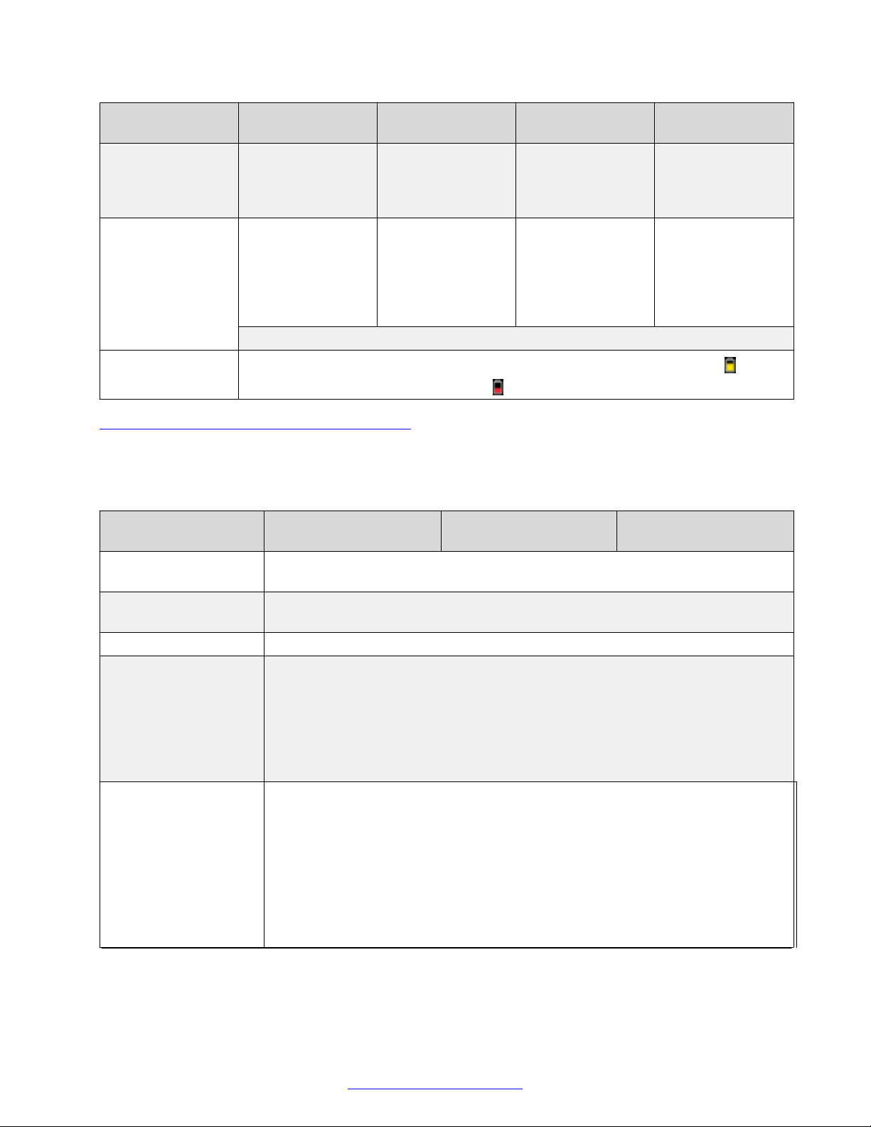
You can use your Avaya Scopia® XT Series to join a videoconference hosted on an external MCU,
like the Scopia® Elite MCU, or you can host a meeting on the built-in MCU if available.
An MCU, or Multipoint Control Unit, connects several endpoints to a single videoconference. It
manages the audio mixing and creates the video layouts, adjusting the output to suit each
endpoint's capabilities.
Figure 8: Hosting a videoconference on the XT Series
You can add a license to most XT Series models to activate the built-in MCU to host
videoconferences locally (see Activating the XT Series and its Optional Features on page 78):
• MCU4 can host videoconferences with up to four participants (one local, three remote).
• MCU9 can host videoconferences with up to nine participants (one local, eight remote).
Important:
The Scopia® XT Executive and Avaya Scopia® XT4300 can host up to four participants.
The embedded MCU can mix standard definition and HD endpoints in the same meeting, without
one impacting on the other. The built-in MCU also supports both wide-screen (16:9) and standard
formats (4:3), incorporating them seamlessly into the video layout.
While generating the video layout, the built-in MCU must shrink each participant's image to fit the
layout. So while the composite video layout remains in HD, each participant's image within the
layout can reach a maximum resolution of 448p.
When using the XT Series as an MCU only, not participating locally, we recommend blocking the
audio and video input from this XT Series during the meeting.
For the best experience when using the Avaya Scopia® XT Series MCU Edition, we recommend
activating the license known as High Bandwidth Option (12Mbps total for all participants) to avoid
April 2015 Avaya Scopia® XT Series Deployment Guide 17
Comments? [email protected]
Page 18

About the XT Series
sending video at the default lower 6Mbps total for all participants (see Activating the XT Series and
its Optional Features on page 78).
Related Links
About the XT Series on page 9
Technical Specifications
This section details the system specifications of the Avaya Scopia® XT Series. Refer to this data
when preparing system setup and afterwards as a means of verifying that the environment still
complies with these requirements.
For detailed safety information consult the Avaya Scopia® XT Series Safety Instructions leaflet
enclosed in the delivery package.
Table 2: Physical device specifications
XT7000 Series XT5000 Series XT4000 Series Scopia® XT
Executive
System power
requirements
Maximum power
consumption
Operating
temperature
Relative humidity 5% to 90% non-condensing
Storage
temperature
Physical
dimensions
Net Weight 1.5 kg (3.5 lb) 2.4 kg (5.3 lb) 10 kg (22.1 lb)
Camera physical
dimensions and net
weight
Camera ports 3 camera ports (6
100-240 VAC,
50/60 Hz, 2 A Max.
66W 60W (205 BTU/h)
Height: 4cm (1.6"), Width: 29cm (11.4"); Depth 16.5cm (6.5") Height: 49.5cm
Height: 15,2cm (6.0"), Width: 25cm (9.8"); Depth 13.5cm (5.3")
with Scopia® XT
Camera Switch)
100-240 VAC, 50/60 Hz, 1.8 A Max. 100-240 VAC,
50/60 Hz, 1 A Max.
0°C to 40°C (32°F to 104°F)
-40°C to 70°C (-40°F to 158°F), ambient
(19.5"), Width:
54.5cm (21.5");
Depth 25cm (9.9")
Includes a built-in
Weight: 1.6 kg (3.5 lb)
2 camera ports (5
with Scopia® XT
Camera Switch)
1 camera port 2 camera ports
camera (can
connect optional
HDMI camera)
Table continues…
18 Avaya Scopia
®
XT Series Deployment Guide April 2015
Comments? [email protected]
Page 19
Microphone Pod
physical
dimensions and net
weight
Microphone Pod
capabilities
Technical Specifications
XT7000 Series XT5000 Series XT4000 Series Scopia® XT
Executive
Diameter: 13.4cm
(5.3"), Weight: 0.45
kg (1 lb)
Premium 3-way
Microphone Pod:
Diameter: 14cm
(5.5"), Weight: 0.3
kg (0.7 lb)
3-way Microphone
Pod:
Diameter: 12cm
(4.7"), Weight: 0.4
kg (0.9 lb)
1-way Microphone
Pod:
Includes a built-in
microphone (can
connect optional
Microphone Pod)
Optional 3-way
Microphone Pod:
XT Remote Control
Unit batteries
360º range
Up to 2 cascaded
pods
2 x AAA batteries. Displays low battery warning on the XT Series monitors: is half-
360º range
Up to 2 cascaded
pods
Frequency response: 50 – 22,000 Hz
charged; is low charge.
180º range
Optional 3-way
Microphone Pod
360º range
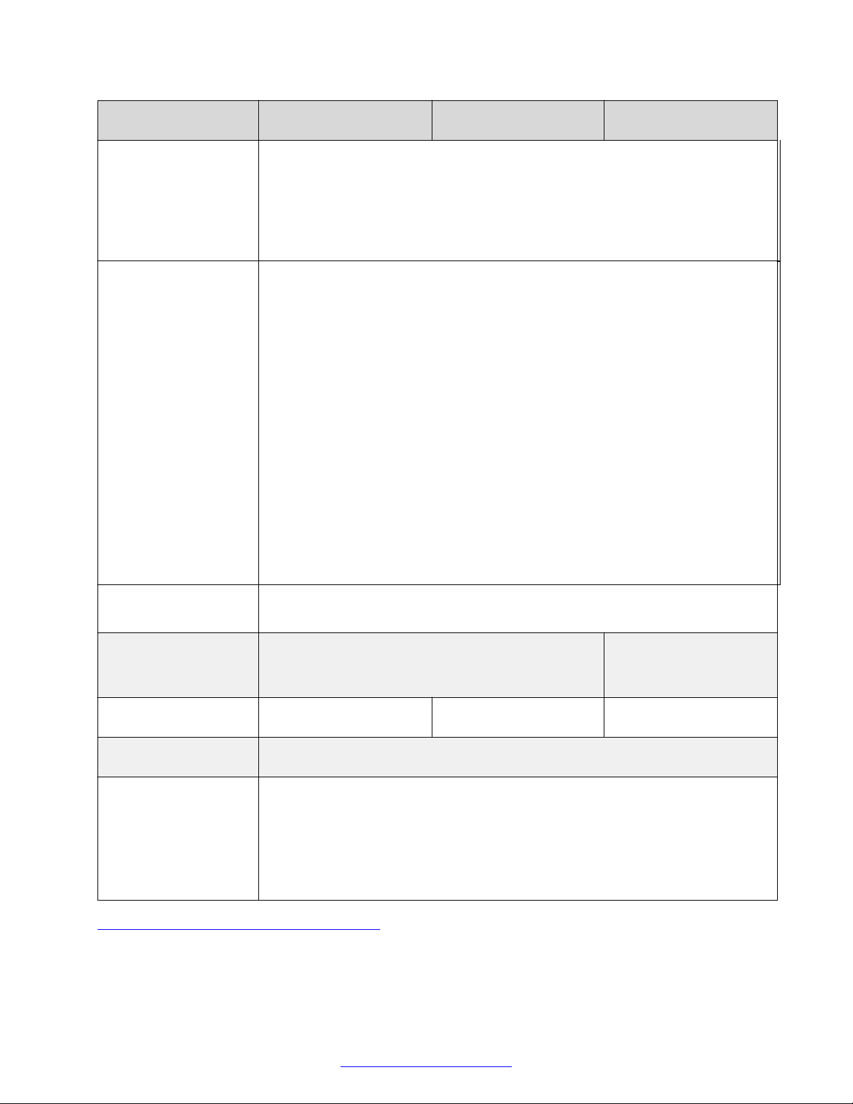
Table 3: Video, audio and control capabilities on page 19 lists the protocols and software
requirements.
Table 3: Video, audio and control capabilities
XT7000 Series and
XT5000 Series
Signaling protocols H.323, SIP, ISDN (requires Scopia® Gateway for ISDN). Each endpoint can use a
different protocol in the same meeting.
Video codecs H.265 (XT7000 Series only), H.264 High Profile SVC (point-to-point calls only), H.
264 High Profile, H.264 SVC, H.264, H.263++, H.263+, H.263
Dual video H.239 (H.323); BFCP (SIP)
HDMI input formats 1920 x 1080 at 25, 30, 50, 60fps (excluding XT4200, optional for XT5000 720)
Scopia® XT Executive XT4000 Series
1280 x 720 at 25, 30, 50, 60fps
720 x 576 at 50fps
720 x 480 at 60fps
640 x 480 at 60fps
Live video resolution 1920 x 1080 at 25, 30, 50, 60fps: HD1080p (excluding XT4200, optional for
XT5000 720)
1280 x 720 at 25, 30, 50, 60fps: HD 720p
1024 x 576 at 25, 30fps: w576p
768 x 448 at 25, 30fps: w448p
704 x 576 at 25, 30fps: 4CIF
704 x 480 at 25, 30fps: 4SIF
Table continues…
April 2015 Avaya Scopia® XT Series Deployment Guide 19
Comments? [email protected]
Page 20
About the XT Series
Presentation video
resolution (from DVI
port)
XT7000 Series and
Scopia® XT Executive XT4000 Series
XT5000 Series
576 x 336 at 25, 30fps
512 x 288 at 25, 30fps: wCIF
400 x 224 at 25, 30fps
352 x 288 at 25, 30fps: CIF
352 x 240 at 25, 30fps: SIF
For XT7000 Series, XT5000 Series, Scopia® XT Executive, and XT4300:
1920 x 1080 at 25, 30, 50, 60fps (optional for XT5000 720)
1600 x 900 at 60fps: HD+ (900p)
1440 x 900 at 60fps: WSXGA
1280 x 1024 at 60, 75fps: SXGA
1280 x 960 at 60, 85fps: UVGA
1280 x 800 at 60fps: WXGA (16:10)
1280 x 768 at 60fps: WXGA (15:9)
For all XT Series:
1280 x 720 at 60fps: HD 720p
1024 x 768 at 60fps: XGA
800 x 600 at 60fps: SVGA
640 x 480 at 60fps: VGA
HDMI output formats 1920 x 1080 at 25, 30, 50, 60fps (excluding XT4200, optional for XT5000 720)
1280 x 720 at 50, 60fps
Video bandwidth Up to 12Mbps for a multipoint call (optional)
Up to 4Mbps for 720p
Up to 10Mbps for 1080p in a SIP point-to-point call or
8128kbps for H.323 calls (720p for XT5000 720)
Camera resolution 1080p 60fps 1080p 30fps (built-in
camera)
1080p 60fps (720p60 for
XT4200)
Audio codecs G.711, G.722, G.722.1, G.722.1 Annex C, G.719, AAC-LC, AAC-LD (G.728, G.
729A optional)
Web browser support • Internet Explorer version 8 or later
• Google Chrome version 11 or later
• Mozilla Firefox version 3.6 or later
• Apple Safari version 5 or later
• Opera version 11 or later
Table 4: Network and security capabilities on page 21 lists the XT Series's network interface and
firewall traversal information.
20 Avaya Scopia
®
XT Series Deployment Guide April 2015
Comments? [email protected]
Page 21
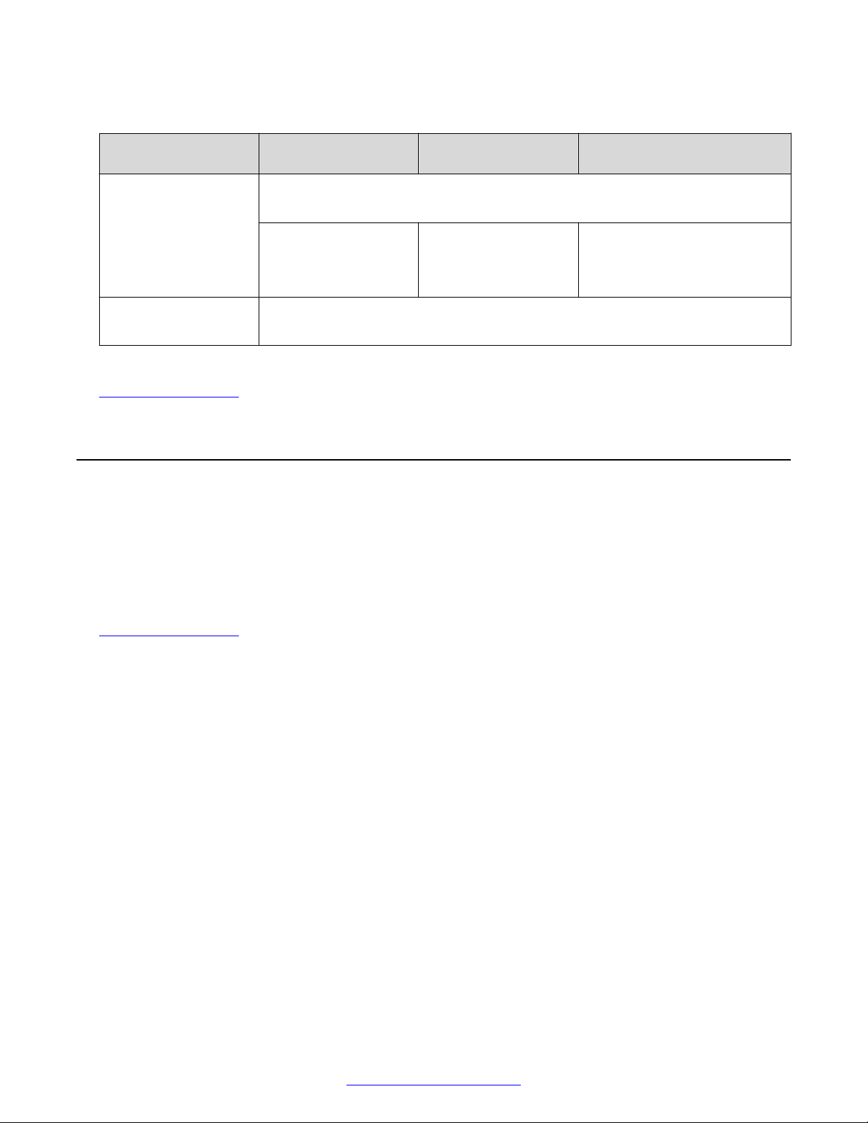
Table 4: Network and security capabilities
Checking the Product Shipment
XT7000 Series and
XT5000 Series
Network Interfaces 2 x 10/100/1000 Base-T full-duplex (RJ-45)
Supports 802.1q authentication, 802.1q VLAN tagging
Second network port
enabled by default
(optional for XT5000
720)
Firewall Traversal Auto NAT discovery HTTP and STUN
XT4000 Series Scopia® XT Executive
Second network port is
optional
H.460.18, H.460.19
Second network port enabled
by default
Related Links
About the XT Series on page 9
Checking the Product Shipment
Inspect the contents of the package for shipping damages. For a list of package contents see the
invoice shipped with your order.
Report any damage or missing items to your distributor or reseller. Keep the package and its
contents for inspection if required for loss or damage claim.
Related Links
About the XT Series on page 9
April 2015 Avaya Scopia® XT Series Deployment Guide 21
Comments? [email protected]
Page 22

Chapter 2: Initial Workflow for Deploying
the Avaya Scopia® XT Series
About this task
To safely set up and perform the required initial settings to start using the Avaya Scopia® XT Series,
follow the recommended workflow described below.
Procedure
1. Decide how to incorporate the XT Series into your deployment, as described in
Topology of the Avaya Scopia® XT Series Deployment on page 24.
For example, decide whether to enable license options such as a built-in MCU, where to
deploy the XT Series, and the ports to open.
2. Read the safety information booklet. Check the XT Series to verify that no shipping damage
occurred, as described in
3. Decide where to place your XT Series, depending on the room setup (see Planning the
Optimal Room Setup on page 42).
4. To quickly connect your XT Series, refer to the Quick Setup Guide for Avaya Scopia® XT
Series. For more detailed information, see
which includes:
• Connect the XT Series to the network.
• Connect monitors if it is used as an endpoint (the Scopia® XT Executive has a built-in
monitor).
• Connect microphones and loudspeakers if it is used as an endpoint (the Scopia® XT
Executive uses a built-in microphone and monitor speakers).
• Connect cameras if used as an endpoint (the Scopia® XT Executive uses a built-in
camera).
5. Choose if you want to remotely control your XT Series (Controlling the XT Series on
page 68). To use the XT Remote Control Unit, first connect a monitor (
Monitors to the XT Series on page 47). Otherwise, use the web interface to control the
system (see Accessing XT Series Web Interface on page 75).
Checking the Product Shipment on page 21.
Setting Up the XT Series Hardware on page 42,
Connecting
Planning the
6. Register your license to activate the XT Series (see Activating the XT Series and its Optional
Features on page 78).
Without a license key to activate the product, you can only use the system in preview mode
for 30 days.
22 Avaya Scopia
®
XT Series Deployment Guide April 2015
Comments? [email protected]
Page 23

7. Get started with the basic configuration to use the XT Series, as described in Initial
Configuration of the XT Series on page 78, including running the quick setup wizard, and
defining network settings.
8. (Recommended) You can prevent users from altering advanced settings by changing the
default administrator PIN code, and you can optionally set a user PIN code to protect basic
settings too (see
Setting PIN Codes for the XT Series on page 156).
To change the default login settings for the XT Series web interface, see
Securing Web
Access to the XT Series on page 157.
9. If your XT Series is an endpoint, not just a server, configure your camera and microphone
settings, as described in:
• Configuring Cameras on page 100
•
Configuring Microphones on page 104
10. If necessary for your deployment, configure your advanced network and call settings, as
described in Configuring Advanced Network Settings on page 116. This includes, for
example:
• Setting the IP address
• Configuring the system in a SIP deployment
• Configuring call settings
• Enabling NAT and Firewall Traversal
• Registering the system with the gatekeeper
• Configuring the system to use an LDAP directory
For more information about deployment setups, see
Planning the Topology of the Avaya
Scopia® XT Series Deployment on page 24 and the Avaya Scopia® Solution Guide.
11. (Optional) If necessary for your organization, you can secure videoconference sessions via
encrypted connections and TLS certificates (see
Securing your XT Series on page 156).
Important:
Using encryption is subject to local regulation. In some countries it is restricted or limited
for usage. For more information, consult your local reseller.
12. If your deployment includes Scopia® Management, you can set up remote monitoring and
management of the XT Series using SNMP messages to send alerts to a central SNMP
server (see Sending Status with SNMP on page 151)..
13. You can remotely backup and restore the XT Series configurations via Scopia
Management, as described in
Enabling System Logs and Remote Initialization on page 175,
®
or use the same configuration files to duplicate the same settings across multiple endpoints
in an organization.
14. To update your software, see
Updating the XT Series on page 153. Some upgrades require
an updated license.
April 2015 Avaya Scopia® XT Series Deployment Guide 23
Comments? [email protected]
Page 24

Chapter 3: Planning the Topology of the
Avaya Scopia® XT Series
Deployment
There are a number of ways that the Avaya Scopia® XT Series can be deployed in a network,
depending on whether you use it as a room system endpoint or a conference hosting system, and
the type of the endpoints connecting to the unit.
As you add more XT Series endpoints, you can manage them centrally with Avaya Scopia
Management. This would enable centralized updating, backing up and control.
Related Links
Topology for Avaya Scopia® XT Series as Endpoints on page 24
Planning the Topology of Avaya Scopia® XT Series with Scopia® XT Desktop on page 25
Planning NAT and Firewall Traversal with Avaya Scopia® XT Series on page 27
Supporting ISDN Connectivity on page 29
Implementing External API Control on page 30
Implementing Port Security for the Avaya Scopia® XT Series on page 31
Topology for Avaya Scopia® XT Series as Endpoints
A Avaya Scopia® XT Series without a built-in MCU is an endpoint and requires an external MCU
such as the Scopia® Elite MCU to host videoconferences (
Endpoints on page 25):
• The MCU performs media processing for endpoints in all locations, including Avaya Scopia
XT Series, Scopia® XT Executive and compatible third-party endpoints.
Figure 9: Avaya Scopia® XT Series as
®
®
• The MCU can handle multiple videoconferences simultaneously.
• Videoconferences are in high-quality, with maximum resolutions of 1080p and 720p, and
include network error resilience using H.264 Scalable Video Coding (SVC) and high profile H.
264 (for details about these features, see
Scopia® XT Executive integrates advanced videoconferencing into a high resolution 24-inch
multimedia LED monitor.
24 Avaya Scopia
®
XT Series Deployment Guide April 2015
Comments? [email protected]
About the XT Series on page 9).
Page 25

Planning the Topology of Avaya Scopia® XT Series with Scopia® XT Desktop
Figure 9: Avaya Scopia® XT Series as Endpoints
Related Links
Planning the Topology of the Avaya Scopia® XT Series Deployment on page 24
Planning the Topology of Avaya Scopia® XT Series with
Scopia® XT Desktop
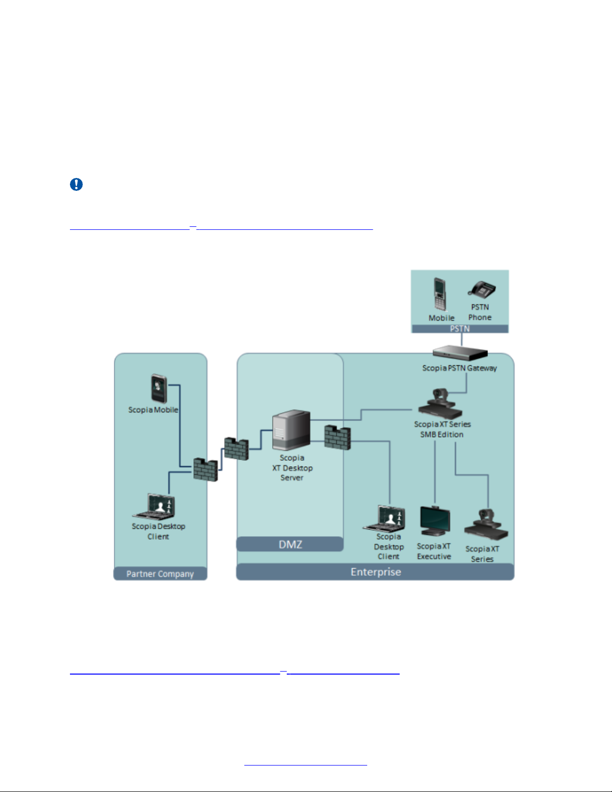
Avaya Scopia® XT Series SMB Edition enables you to locally host videoconferences using its builtin MCU, and extends your videoconferences to participants joining from a computer (with Scopia
Desktop Client) or a mobile device (using Scopia® Mobile).
For example, when you start a videoconference with the XT Series hosting the call, you can add
other participants by asking them to connect via a web link to the Scopia® XT Desktop server, which
would automatically install and launch Scopia® Desktop Client on their computers, or Scopia
Mobile on their mobile devices.
The main features of the Avaya Scopia® XT Series SMB Edition include:
• Remote users can easily connect to a meeting hosted by the built-in MCU on the XT Series, by
connecting via the Scopia® XT Desktop server.
The deployment has very few components. You do not need additional hardware like an
external MCU, Avaya Scopia® PathFinder for firewall traversal, or Avaya Scopia® ECS
Gatekeeper for routing calls.
• The included Scopia® XT Desktop provides built-in NAT and firewall traversal functionality,
enabling secure remote connections from Scopia® Mobile and Scopia® Desktop Clients.
You can enable this functionality via the XT Series license.
®
®
April 2015 Avaya Scopia® XT Series Deployment Guide 25
Comments? [email protected]
Page 26
Planning the Topology of the Avaya Scopia® XT Series Deployment
The Avaya Scopia® XT Series SMB Edition includes the following options:
• Full SMB4 - Basic MCU level with up to four participants: one local and three remote endpoints
or PC clients.
• Full SMB9 - Advanced MCU level, with one local participant and up to eight remote endpoints
or PC clients.
There is no local endpoint if you deploy the XT Series as a server.
Important:
The Scopia® XT Executive and Avaya Scopia® XT4300 can host up to four participants.
Figure 10: Avaya Scopia® XT Series SMB Edition Deployment on page 26 shows a typical
topology for the Avaya Scopia® XT Series SMB Edition solution. For more information, see the
Solution Guide for Scopia® Solution.
Figure 10: Avaya Scopia® XT Series SMB Edition Deployment
As you add more XT Series endpoints, you can also manage them centrally with Scopia
Management. This would enable centralized updating, backing up and control.
Related Links
Planning the Topology of the Avaya Scopia® XT Series Deployment on page 24
26 Avaya Scopia
®
XT Series Deployment Guide April 2015
Comments? [email protected]
®
Page 27
Planning NAT and Firewall Traversal with Avaya Scopia® XT Series
Planning NAT and Firewall Traversal with Avaya Scopia
XT Series
The Avaya Scopia® XT Series fully supports NAT and firewall traversal, enabling you to place the
unit behind a NAT router or firewall and connect with other endpoints seamlessly. This section
describes the available methods to incorporate NAT and firewall traversal with XT Series:
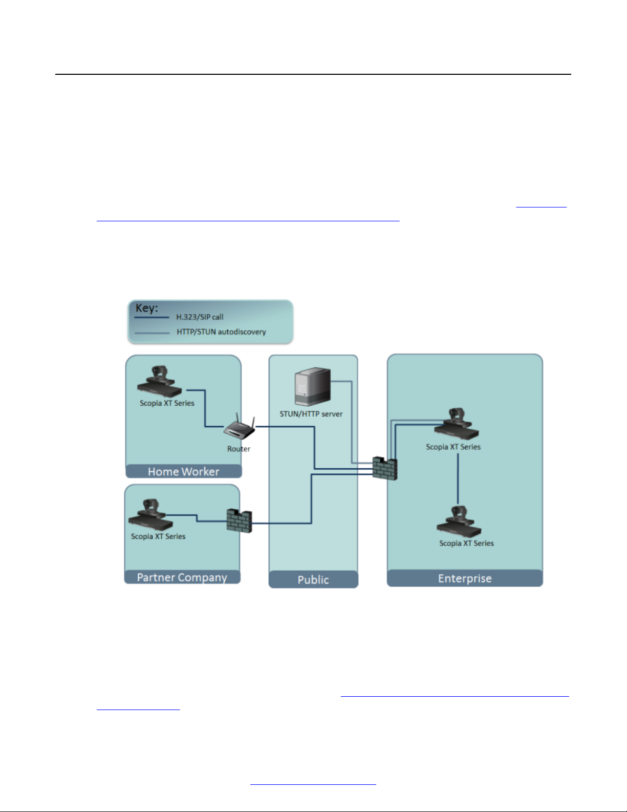
• Using a Avaya HTTP server or a STUN public server for NAT and firewall traversal
When the XT Series hosts a videoconference with endpoints outside the enterprise (
Using an HTTP/STUN Server for NAT and Firewall Traversal on page 27), it first queries an
HTTP or STUN server to discover its public IP address, then sends it to any external endpoints
wishing to join the conference. The external endpoints then answer the call using the IP
address provided. Configure the XT Series for HTTP or STUN autodiscovery. A STUN server
enables you to directly dial an endpoint behind a NAT or firewall by giving that computer’s
public internet address.
Figure 11:
®
Figure 11: Using an HTTP/STUN Server for NAT and Firewall Traversal
This approach works well in simple NAT and firewall traversal deployments, typically used by
home offices and Small Medium Businesses (SMBs).
• Using PathFinder server or other H.460 server for NAT/firewall traversal
Endpoints in the private network can communicate with public endpoints via an H.460 NAT/
firewall traversal server, like the PathFinder (see
Traversal Server on page 28). Endpoints in the public network can join a conference hosted
April 2015 Avaya Scopia® XT Series Deployment Guide 27
Comments? [email protected]
Figure 12: Using a separate NAT and Firewall
Page 28
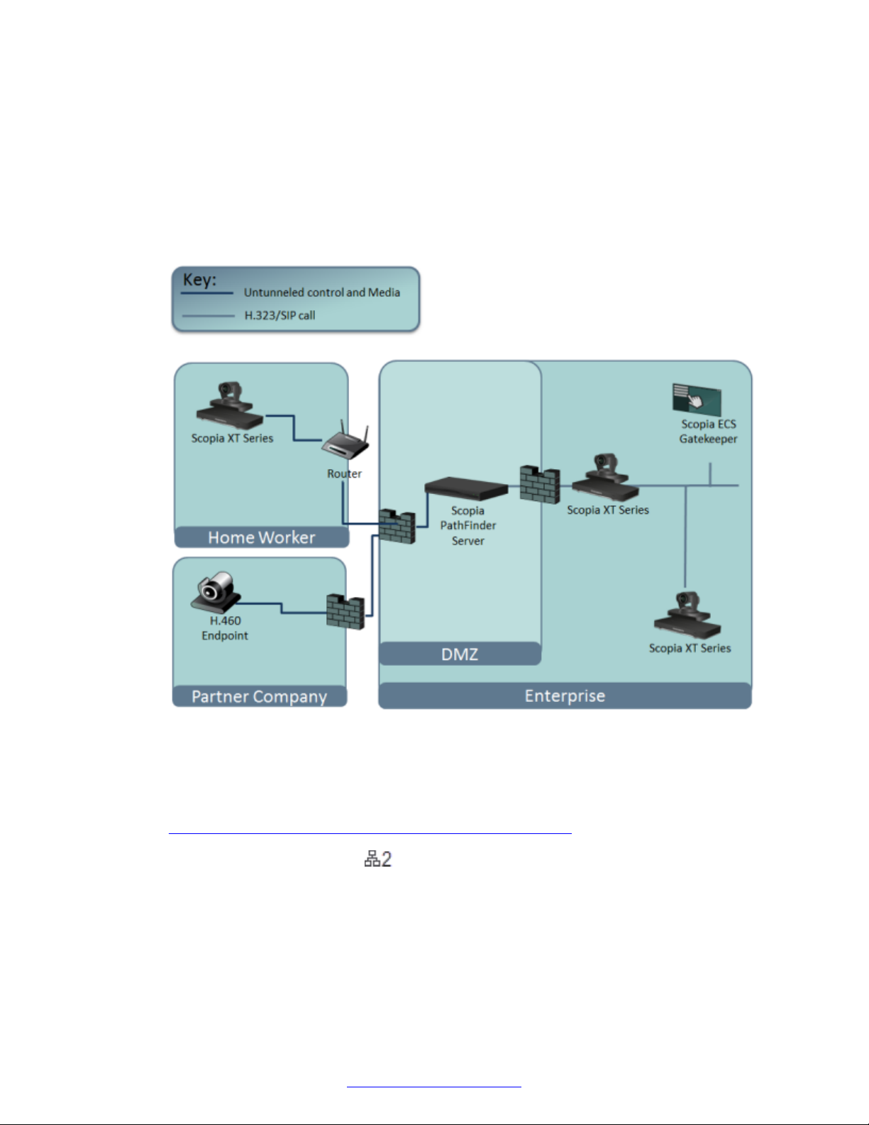
Planning the Topology of the Avaya Scopia® XT Series Deployment
in the private network via the traversal server if there is an open connection through the
firewall.
A dedicated PathFinder server offers external endpoints a static address when joining
conferences hosted in your organization. You can dial [email protected] to
access from outside the firewall, or you can dial 1234 directly if you deployed the Scopia
PathFinder client.
Configure the PathFinder server as the XT Series's gatekeeper and enable H.460.
®
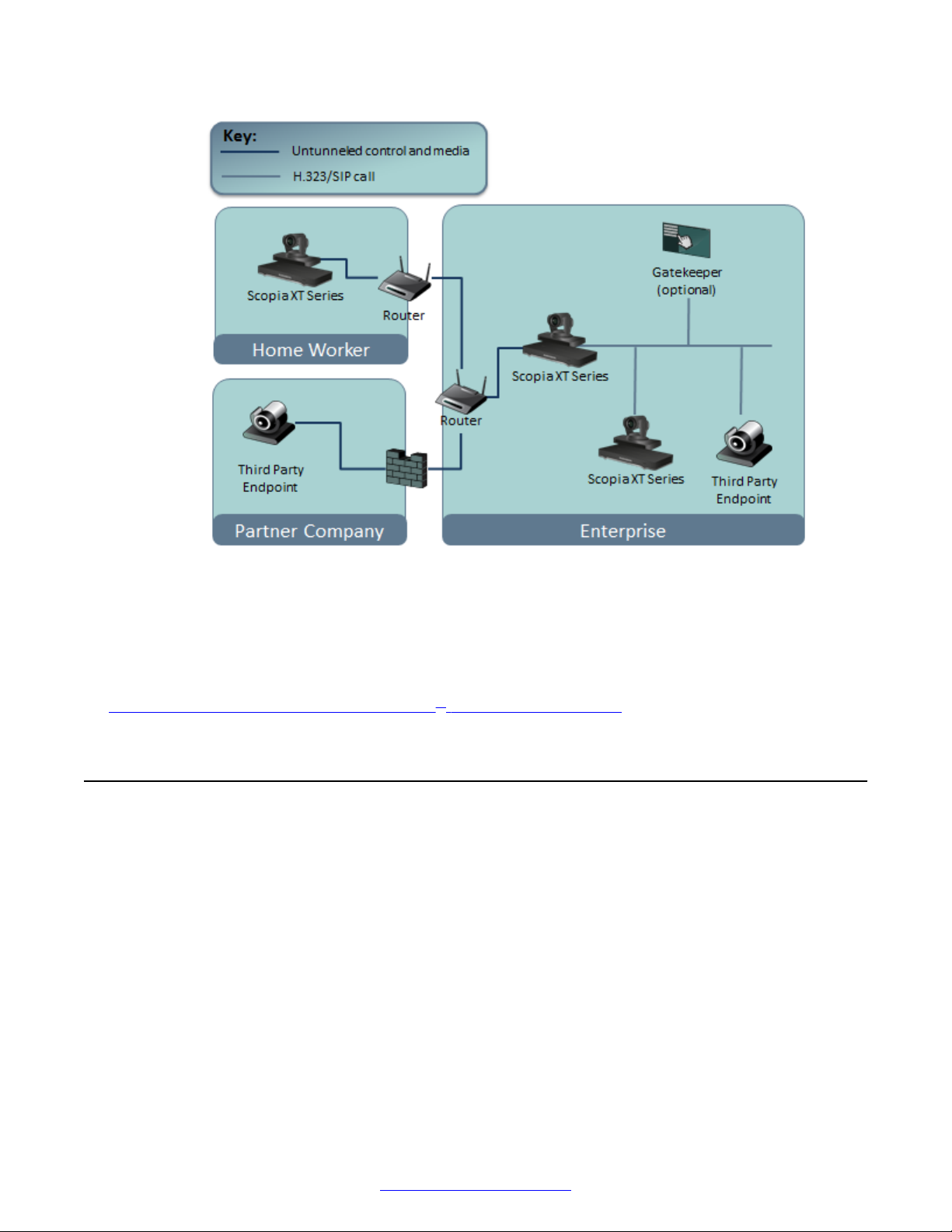
• Using the XT Series for NAT and firewall traversal
In cases where your organization has no sophisticated firewall protection, the XT Series can
straddle the two network zones using the both network ports provided on the XT Codec Unit
(see
Figure 13: Using XT Series for NAT and Firewall Traversal on page 29).
Activate the second network port with the correct license, then connect one port to the
public network and the other to your private network. All communication passes through the XT
Series which acts as the virtual conference room for all the endpoints.
28 Avaya Scopia
Figure 12: Using a separate NAT and Firewall Traversal Server
®
XT Series Deployment Guide April 2015
Comments? [email protected]
Page 29
Supporting ISDN Connectivity
Figure 13: Using XT Series for NAT and Firewall Traversal
A gatekeeper allows the XT Series to dial aliases instead of IP addresses for endpoints in the
private network, while for public endpoints, you must dial IP addresses. Without a gatekeeper,
all endpoints must be referenced using IP addresses.
Related Links
Planning the Topology of the Avaya Scopia® XT Series Deployment on page 24
Supporting ISDN Connectivity
About this task
The Avaya Scopia® XT Series supports ISDN connectivity, allowing calls from endpoints to be
routed to the relevant videoconference via the Scopia® Gateway for ISDN.
For deployments without a gatekeeper, you can dial ISDN endpoints by simply dialing the ISDN
number. To do so, you must first configure the endpoint with your Scopia® Gateway for ISDN, as
described below. The system then automatically and transparently takes care of setting the bit rate
and call routing through the Scopia® Gateway.
A single gateway can serve multiple endpoints. For example, if your organization needs to enable 5
Avaya Scopia® XT Series endpoints with ISDN connectivity (at a speed of 256bps), you can use
one the Scopia® Gateway for ISDN, which supports 5 concurrent calls of 256bps each.
April 2015 Avaya Scopia® XT Series Deployment Guide 29
Comments? [email protected]
Page 30
Planning the Topology of the Avaya Scopia® XT Series Deployment
With the gateway approach less communication lines are needed. As all gateways do not connect at
the same time and not all calls are ISDN, many more endpoints can share the same ISDN
connection and gateway.
Before you begin
Enable Peer-to-Peer mode in the Scopia® Gateway for ISDN. For more information, see the
Scopia® Gateway documentation.
Procedure
1. Access the XT Series web interface, as described in
Accessing XT Series Web Interface on
page 75.
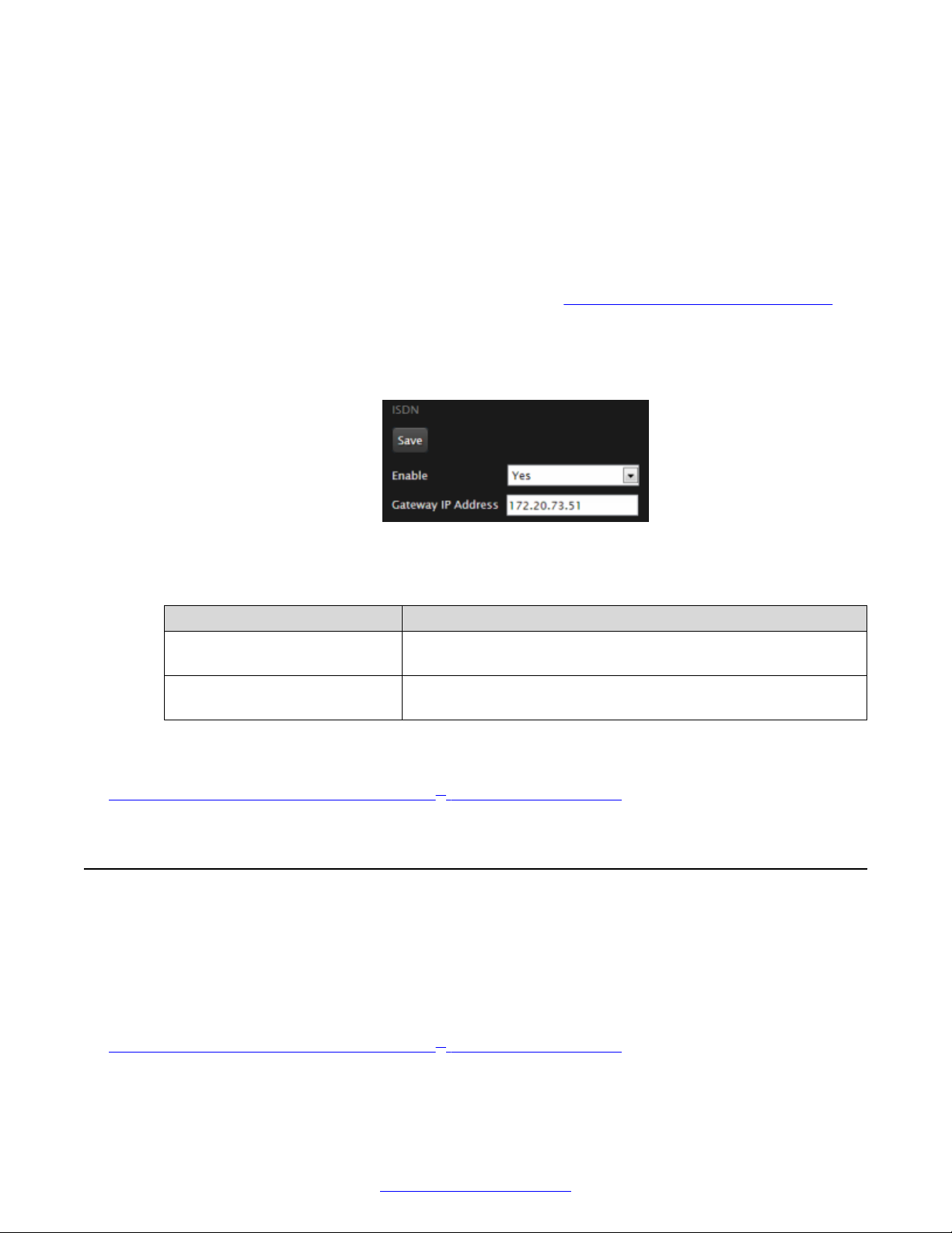
2. Select Administrator Settings > Protocols > ISDN.
3. Configure the IDSN settings as described below:
Figure 14: Enabling ISDN connectivity
Table 5: Supporting ISDN Connectivity
Field Description
Enable Select Yes to allow this Avaya Scopia® XT Series to quickly dial
ISDN endpoints via the Scopia® Gateway for ISDN.
Gateway IP Address Enter the IP address of the Scopia® Gateway for ISDN used by
your organization.
4. Select Save.
Related Links
Planning the Topology of the Avaya Scopia® XT Series Deployment on page 24
Implementing External API Control
You can control the XT Codec Unit using the Avaya Scopia® XT Series API (requires integration
with AMX, Creston, or Extron control devices). Contact Avaya customer support to receive the
Reference Guide for Avaya Scopia® XT Series API, which includes the list of commands over the
Ethernet interface.
Related Links
Planning the Topology of the Avaya Scopia® XT Series Deployment on page 24
30 Avaya Scopia
®
XT Series Deployment Guide April 2015
Comments? [email protected]
Page 31

Implementing Port Security for the Avaya Scopia® XT Series
Implementing Port Security for the Avaya Scopia® XT
Series
The Avaya Scopia® XT Series provides video technology for room conferencing, including support
for dual stream 1080p video, high quality data sharing, high quality full band audio and a highcapacity embedded MCU (selected models).
To enable an external XT Series endpoint to communicate with Scopia® Solution components within
the organization's network, you need to open firewall ports between the external XT Series endpoint
and the organization. This section details the ports used for the Avaya Scopia® XT Series and the
relevant configuration procedures:
Related Links
Planning the Topology of the Avaya Scopia® XT Series Deployment on page 24
Opening Ports for the XT Series on page 31
Configuring the TCP or UDP Port Range on the Avaya Scopia® XT Series on page 40
Opening Ports for the XT Series
You can deploy Avaya Scopia® XT Series endpoints either inside or outside the enterprise network.
When Scopia® Solution components are located inside the network, and one or more XT Series
endpoints are outside the network, you must open ports in the firewall to enable the endpoint's
functionality.
Since the location of the XT Series is not fixed, the ports' source and destination differ depending on
your XT Series topology. There are two main deployment topologies for the XT Series, each with
optional additional components:
• XT Series as an endpoint (standard topology)
• XT Series with Scopia® XT Desktop (Avaya Scopia® XT Series SMB Edition)
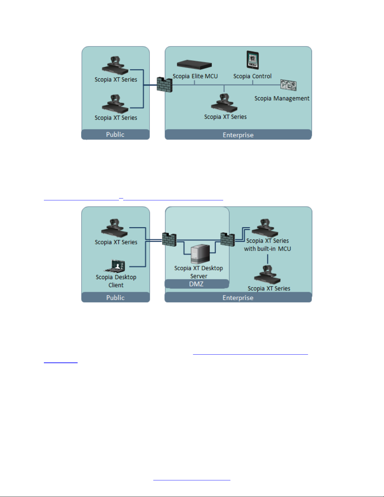
Typically, XT Series endpoints connect to a conference managed by Scopia® Management, and
hosted on the Scopia® Elite MCU. XT Series endpoints may be both within and outside the
enterprise. See
Figure 15: Standard topology for Avaya Scopia® XT Series on page 32.
April 2015 Avaya Scopia® XT Series Deployment Guide 31
Comments? [email protected]
Page 32
Planning the Topology of the Avaya Scopia® XT Series Deployment
Figure 15: Standard topology for Avaya Scopia® XT Series
In contrast, in the Avaya Scopia® XT Series SMB Edition topology, Scopia® Desktop Clients join the
conference via Scopia® XT Desktop server, located in the DMZ. The Scopia® XT Desktop server
then connects to an XT Series endpoint with built-in MCU located inside the enterprise. External and
internal XT Series endpoints connect directly to the XT Series endpoint with built-in MCU. See
Figure 16: Avaya Scopia® XT Series SMB Edition topology on page 32.
Figure 16: Avaya Scopia® XT Series SMB Edition topology
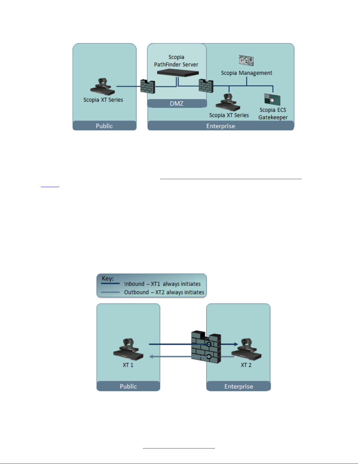
Avaya Scopia® PathFinder provides a complete firewall and NAT traversal solution for H.323
deployments, enabling secure connectivity between enterprise networks and remote sites.
PathFinder enables registered external endpoints to traverse the firewall without requiring you to
open any dedicated ports for the XT Series. See
Figure 17: XT Series deployment with
PathFinder on page 33
32 Avaya Scopia
®
XT Series Deployment Guide April 2015
Comments? [email protected]
Page 33
Implementing Port Security for the Avaya Scopia® XT Series
Figure 17: XT Series deployment with PathFinder
In each of the topologies, the XT Series can be located either inside or outside the enterprise. You
need to open different ports depending on the topology, and the location of the endpoints. The
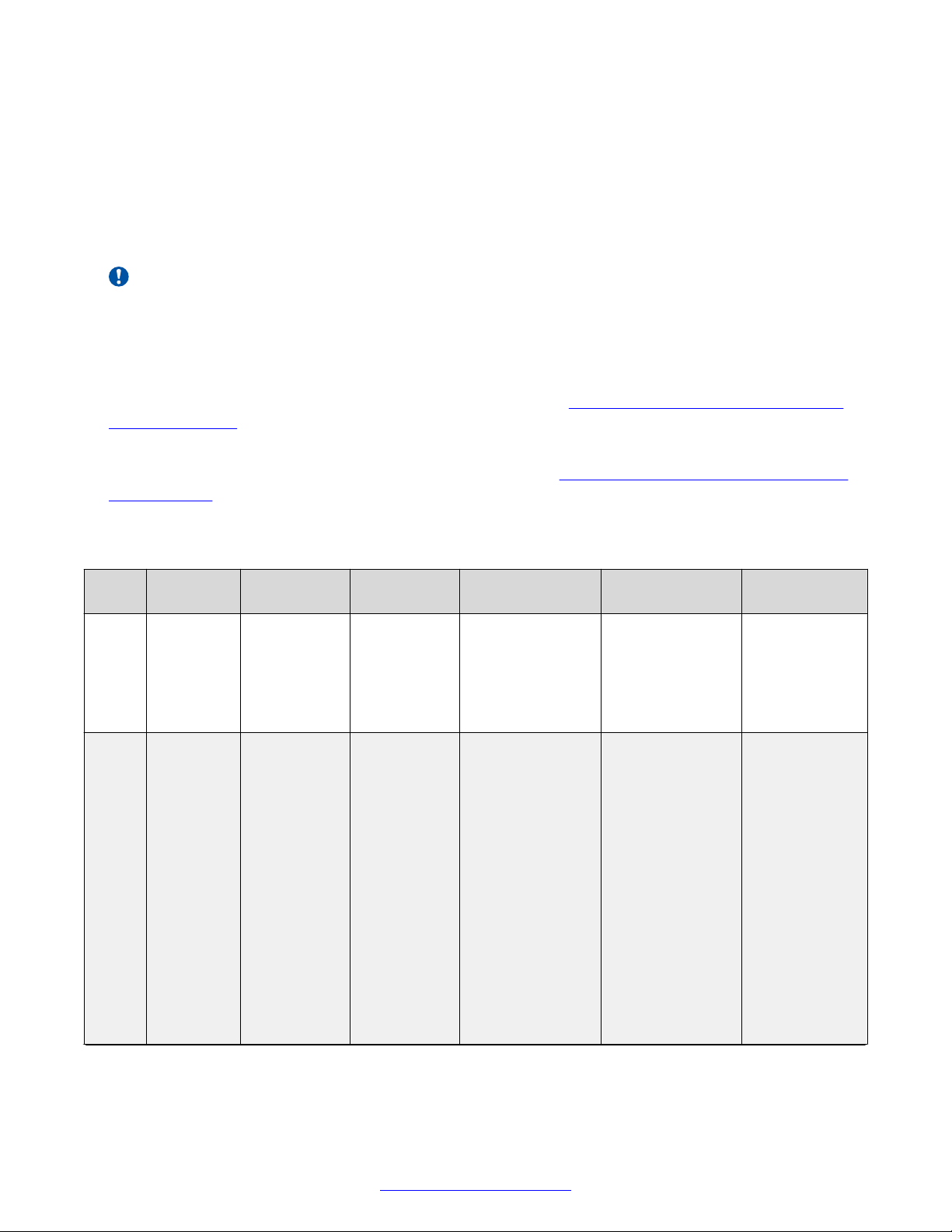
source for a port is the sender of data packets, and the destination is the receiver. There are two
types of ports which require opening (see
Figure 18: Inbound and outbound ports for the XT
Series on page 33):
• Bidirectional ports, which allow the XT Series to send and receive data packets on the same
port.
• Unidirectional ports, which allow the XT Series to either initiate communication or receive data
packets.
For a unidirectional port, you must designate it as inbound or outbound. A port is inbound if its
source is sending to a destination protected by the firewall (for example, data sent from an
external XT Series to Scopia® Management). A port is outbound if its destination is receiving
data from a source protected by the firewall (for example, data sent from Scopia® Management
to an external XT Series).
Figure 18: Inbound and outbound ports for the XT Series
April 2015 Avaya Scopia® XT Series Deployment Guide 33
Comments? [email protected]
Page 34
Planning the Topology of the Avaya Scopia® XT Series Deployment
Depending on the location of the XT Series, a unidirectional port might be inbound to the
organization or outbound from the organization. For example:
• Port 161 is an outbound port from Scopia® Management or an SNMP management server to
an external XT Series.
• Port 162 is an inbound port from an external XT Series to Scopia® Management or an SNMP
management server.
Important:
On stateful firewalls, ports are left open to response data for an allocated period of time after the
initial request. For unidirectional ports, this response is the only data allowed through in the
opposite direction. On bidirectional ports, data can be initiated and sent through in both
directions.
If you are opening unidirectional ports for the XT Series, see Table 6: Unidirectional ports to open
for the XT Series on page 34. You need to determine if they are inbound or outbound depending
on the source and destination.
If you are opening bidirectional ports for the XT Series, see Table 7: Bidirectional ports to open for
the XT Series on page 39.
Table 6: Unidirectional ports to open for the XT Series
Port
Range
69 TFTP
80 HTTP
Protocol Source Destination Functionality Result of
XT Series TFTP server Enables the XT
(TCP)
(TCP)
Web client
(HTTP) /
Scopia
Desktop
Client
®
XT Series Enables you to
Series to send
configuration, log,
and other system
files to a TFTP
server.
remotely manage
the XT Series via
the XT Series web
user interface
using HTTP.
Enables you to
manually activate
Screen Link to
share content
from your
computer to the
XT Series without
having a physical
connection
between the two.
Blocking Port
The XT Series
cannot send files
to a TFTP server.
You cannot
access the XT
Series web server
using HTTP.
You cannot
manually activate
Screen or Mobile
Link.
Sonic proximity
detection can still
activate Screen or
Mobile Link
automatically
even if this port is
closed.
Required
Optional
Recommended
if accessing the
XT Series
remotely via a
web browser
using HTTP.
Recommended
if using Screen
Link or Mobile
Link.
Table continues…
34 Avaya Scopia
®
XT Series Deployment Guide April 2015
Comments? [email protected]
Page 35
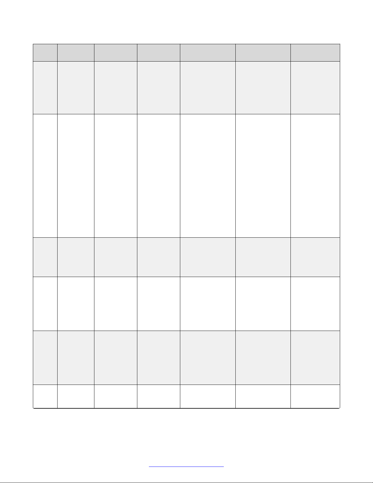
Implementing Port Security for the Avaya Scopia® XT Series
Port
Protocol Source Destination Functionality Result of
Range
80 HTTP
(TCP)
123 SNTP
(UDP)
161 SNMP
(UDP)
162 SNMP
(UDP)
389 LDAP
(TCP)
Enables you to
manually activate
Mobile Link to
transfer a meeting
from a mobile
device to an XT
Series endpoint.
XT Series Web servers
on the
internet /
Scopia
®
Desktop
server Proxy
Enables the XT
Series to perform
NAT autodiscovery and
detect its location
via HTTP. This
enables the XT to
select the
appropriate
system language.
Enables you to
use Mobile Link to
transfer a meeting
from a mobile
device to an XT
Series endpoint.
XT Series SNTP Server Enables the XT
Series to receive
the Internet UTC
time.
Scopia
Management/
SNMP server
XT Series Scopia
XT Series Scopia
®
XT Series Enables you to
check the system
status via SNMP.
®
Management/
SNMP server
®
Management/
Enables the XT
Series to send
SNMP traps.
Enables the XT
Series to request
contact
Blocking Port
The XT Series
cannot perform
NAT autodiscovery or
detect its location
via HTTP.
You cannot
transfer a meeting
from a mobile
device to an XT
Series endpoint.
The XT Series
cannot receive the
Internet UTC time
from the SNTP
server.
You cannot check
the status of the
system via SNMP.
The XT Series
cannot send
SNMP traps.
The XT Series
cannot request
contact
Required
Recommended
Recommended
Mandatory if
using Scopia
®
Management or
an SNMP
server to
manage the XT
Series.
Mandatory if
using Scopia
®
Management or
an SNMP
server to
manage the XT
Series.
Mandatory if
using a remote
directory.
Table continues…
April 2015 Avaya Scopia® XT Series Deployment Guide 35
Comments? [email protected]
Page 36
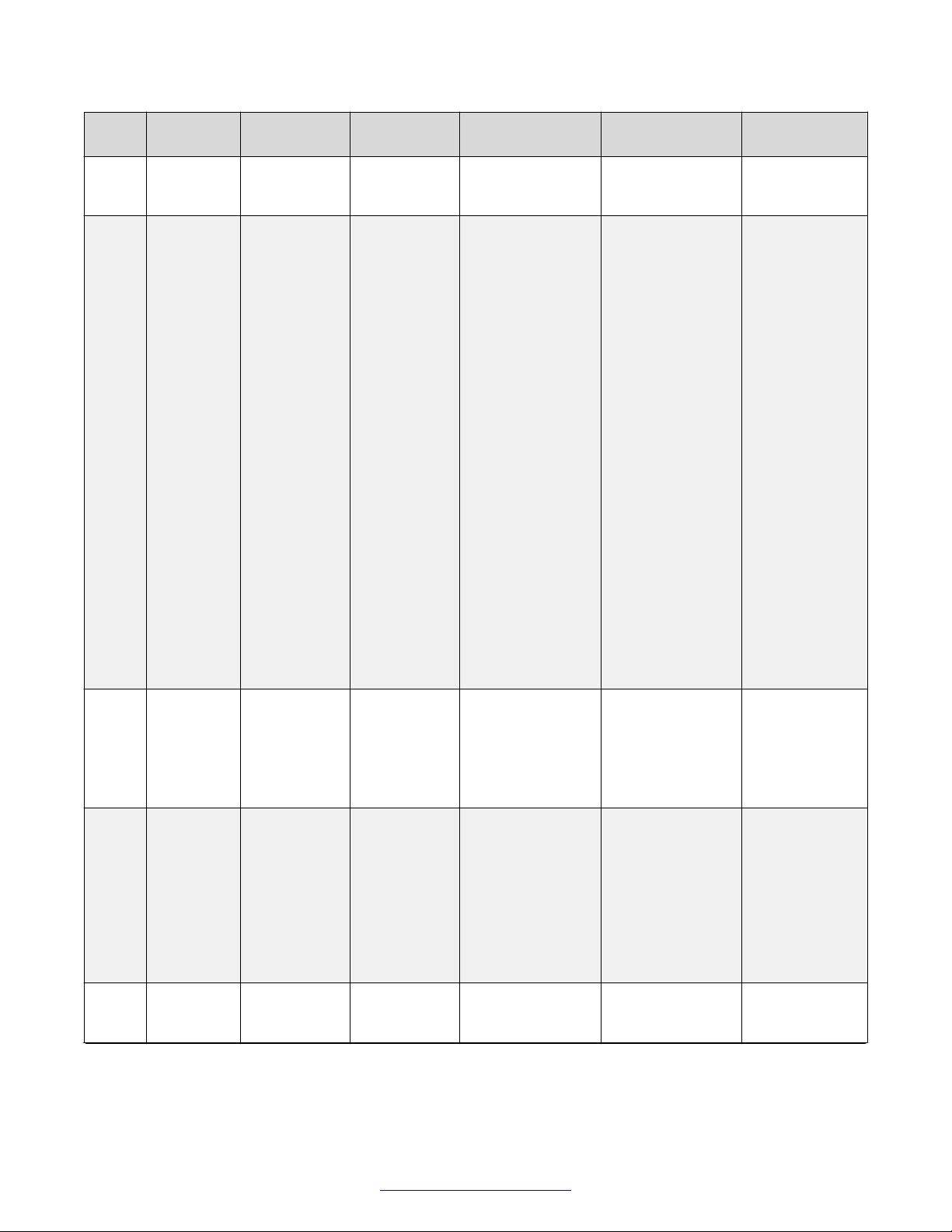
Planning the Topology of the Avaya Scopia® XT Series Deployment
Port
Protocol Source Destination Functionality Result of
Range
LDAP
directory
443 HTTPS
(TCP)
Web client
(HTTPS) /
Scopia
®
XT Series Enables you to
Desktop
Client
443 HTTPS XT Series Scopia
Desktop
server Proxy
1718 H.
225.0/RAS
(UDP)
XT Series Multicast IP
address
224.0.0.41
(all
gatekeepers)
1719 H.
225.0/RAS
XT Series H.323
gatekeeper
(UDP)
Required
Blocking Port
information from
the LDAP server.
information from
the remote
directory.
remotely perform
management
tasks using the
XT Series web
user interface via
HTTPS.
Enables you to
manually activate
Screen Link to
share content
from your
computer to the
XT Series without
having a physical
connection
A web client
cannot access the
XT Series web
server via HTTPS.
You cannot
manually activate
Screen or Mobile
Link.
Sonic proximity
detection can still
activate Screen or
Mobile Link
automatically
even if this port is
closed.
Recommended
if accessing the
XT Series via a
web browser
using HTTPS.
Recommended
if using Screen
Link or Mobile
Link.
between the two.
Enables you to
manually activate
Mobile Link to
transfer a meeting
from a mobile
device to an XT
Series endpoint.
®
Enables you to
use Mobile Link to
transfer a meeting
from a mobile
device to an XT
You cannot
transfer a meeting
from a mobile
device to an XT
Series endpoint.
Recommended
Series endpoint.
Enables the XT
Series to
automatically
identify the correct
gatekeeper to
use.
You must define
the gatekeeper
manually since
the XT Series
cannot
automatically
Optional
identify the correct
gatekeeper to
use.
Enables H.323
call signaling and
The XT Series
cannot use
Mandatory for
H.323
deployments.
Table continues…
36 Avaya Scopia
®
XT Series Deployment Guide April 2015
Comments? [email protected]
Page 37
Implementing Port Security for the Avaya Scopia® XT Series
Port
Protocol Source Destination Functionality Result of
Range
3336 XML (TCP) XT Series Scopia
Management
33363337
XML (TCP) Scopia® XT
Desktop
XT Series Enables Scopia
server
3338 XML (TCP) Scopia
®
XT Series Enables Scopia
Control
3339 XML (TCP) Scopia
®
XT Series Enables Scopia
Control
3341 XML (TCP) Scopia
®
XT Series Enables XT
Management
34783479
STUN
(UDP)
XT Series STUN server Enables XT
Required
Blocking Port
gatekeeper
services.
®
Enables an XT
Series endpoint to
request a list of
meetings
scheduled for it on
that day from
Scopia
®
gatekeeper
services.
XT Series
endpoints cannot
send Scopia
®
Management
requests about
meeting
information.
Recommended
Management.
®
XT Desktop
server to request
and receive the
Scopia® XT
Desktop clients
cannot connect to
the XT Series.
Mandatory if
using Scopia
XT Desktop
server.
®
XT Series' status
information.
®
Control to
communicate with
XT Series.
®
Control to request
and receive
system status
messages from
the XT Series.
Scopia® Control
cannot
communicate with
the XT Series.
Scopia® Control
cannot receive
system status
messages from
the XT Series,
and cannot
Mandatory if
using Scopia
Control.
Mandatory if
using Scopia
Control.
®
®
function.
Series to receive
notifications from
Scopia
®
Management with
its daily list of
XT Series
endpoints cannot
receive meeting
information from
Scopia
®
Management.
Recommended
meetings, meeting
participants, and
any meeting
updates.
Series endpoints
to automatically
discover the
presence of a
firewall or NAT,
via the STUN
XT Series
endpoints cannot
automatically
discover the
presence of a
firewall or NAT
(only manual
Optional
server, and to
Table continues…
April 2015 Avaya Scopia® XT Series Deployment Guide 37
Comments? [email protected]
Page 38
Planning the Topology of the Avaya Scopia® XT Series Deployment
Port
Protocol Source Destination Functionality Result of
Range
8554 RTSP
XT Series Scopia
(TCP)
55000 TCP Scopia® XT
Control
55001 UDP Scopia® XT
Control
55003 AT
commands
(TCP)
Scopia
Management/
Remote
®
management
console
(Creston/
Extron)
55099 Software
upgrade
(TCP)
Scopia
Management/
XT Series
®
determine their
public IP address.
®
Desktop
Client
Enables you to
use Screen Link
to share content
from your
computer to the
XT Series without
having a physical
connection
between the two.
XT Series Enables you to
control the
Scopia® XT
Executive using a
PC keyboard and
mouse.
XT Series Enables you to
control the
Scopia® XT
Executive using a
PC keyboard and
mouse.
XT Series Enables Scopia
Management and
the remote
management
console to
remotely manage
the XT Series.
XT Series Enables you to
remotely upgrade
Blocking Port
configuration is
available).
You cannot share
content from your
computer to the
XT Series.
You cannot use
Scopia® XT
Control to
manage the
Scopia® XT
Executive.
You cannot use
Scopia® XT
Control to
manage the
Scopia® XT
Executive.
®
Scopia
Management and
the remote
management
console cannot
manage the XT
Series.
You cannot
upgrade XT
Series software
Required
Recommended
(required to
share content
from a
computer with a
personal
firewall)
Mandatory if
using Scopia
®
XT Control to
manage the
Scopia® XT
Executive using
a PC keyboard
and mouse
from a
computer with a
personal
firewall.
Mandatory if
using Scopia
®
XT Control to
manage the
Scopia® XT
Executive using
a PC keyboard
and mouse
from a
computer with a
personal
firewall.
®
Mandatory if
using Scopia
®
Management or
the remote
management
console to
manage the XT
Series.
Mandatory to
upgrade XT
Table continues…
38 Avaya Scopia
®
XT Series Deployment Guide April 2015
Comments? [email protected]
Page 39
Implementing Port Security for the Avaya Scopia® XT Series
Port
Protocol Source Destination Functionality Result of
Range
Software
Upgrade
application
60123 Telnet
Telnet client XT Series Enables you to
(TCP)
Important:
Since source and destination are not fixed on bidirectional ports, we refer to them here as
Connection Points. Each connection point can be both the source and the destination.
Table 7: Bidirectional ports to open for the XT Series
Port
Range
1720 H.225.0 /Q.
32303250
32303313
Protocol Connection
Points
XT Series, Any
931
H.225.0 /
Q931, H.245,
SIP (TCP)
RTP, RTCP
(UDP)
H.323 endpoint
XT Series, Any
SIP or H.323
endpoint
XT Series, Any
SIP or H.323
endpoint
Functionality Result of Blocking
Enables H.323 call
signaling (Q.931) for
the XT Series.
Enables H.323 call
control signaling (Q.
931), media control
signaling (H.245), SIP
(TCP) call signaling,
and BFCP signaling.
These are dynamic
TCP ports which the
XT Series uses to
connect simultaneous
H.323 and SIP calls.
Enables H.323 and
SIP media (audio,
video, H.224/data
RTP) and media
control (RTCP).
XT Series
software.
remotely manage
the XT Series
using the CLI
application via
Telnet.
Port
The XT Series cannot
connect H.323 calls.
The XT Series cannot
connect SIP or H.323
calls.
No media can be
exchanged in H.323 or
SIP calls.
Blocking Port
using Scopia
®
Management or a
standalone XT
Series software
upgrade
application.
Telnet cannot
access the XT
Series CLI
application, and
cannot remotely
manage it.
Required
Series software
remotely.
Optional
Required
Mandatory
Mandatory to
support H.323
calls, and to
support SIP calls
on TCP.
To configure,
see Configuring
the TCP or UDP
Port Range on
the Avaya
Scopia® XT
Series on
page 40.
Mandatory to
support H.323
and SIP calls.
To configure,
see Configuring
the TCP or UDP
Table continues…
April 2015 Avaya Scopia® XT Series Deployment Guide 39
Comments? [email protected]
Page 40
Planning the Topology of the Avaya Scopia® XT Series Deployment
Port
Range
5060 SIP (TCP/
5061 SIP (TCP) XT Series, Any
5070 BFCP (TCP) XT Series, Any
Protocol Connection
Points
XT Series, Any
UDP)
SIP endpoint
SIP endpoint
SIP endpoint
Functionality Result of Blocking
Port
These are dynamic
UDP ports which the
XT Series uses to
connect simultaneous
H.323 and SIP calls.
Enables SIP call
signaling for TCP and
UDP.
Enables SIP call
signaling for TLS.
Enables SIP video
content (presentation)
signaling.
The XT Series cannot
connect SIP calls over
TCP and UDP.
The XT Series cannot
securely connect SIP
calls over TCP with
TLS.
Video content
(presentation) is not
available for SIP.
Related Links
Implementing Port Security for the Avaya Scopia® XT Series on page 31
Required
Port Range on
the Avaya
Scopia® XT
Series on
page 40.
Mandatory to
support SIP calls
over TCP and
UDP.
Mandatory to
support secure
SIP calls over
TCP with TLS.
Mandatory to
support video
content in SIP
calls.
Configuring the TCP or UDP Port Range on the Avaya Scopia® XT Series
About this task
You can configure the TCP or UDP port range by setting the base port, which is the lower end of the
port range (if, for example, port 3230 is busy).
The Avaya Scopia® XT Series uses dynamic TCP ports 3230-3250 for the following:
• H.225.0: An H.323 protocol that specifies the messages and procedures used by gatekeepers
to set up calls.
• Q.931: A telephony protocol used for establishing and terminating the connection in H.323
calls.
• H.245: A Control Protocol used for multimedia communication; enables transferring information
about the device capabilities, as well as opening/closing the logical channels that carry media
streams.
• SIP: A signaling protocol used for creating, modifying, or terminating multimedia connections
between two or more participants.
The Avaya Scopia® XT Series uses dynamic UDP ports 3230-3248 for enabling real-time H.323 and
SIP media, including audio, video, and H.224/data (RTP), and media control (RTCP).
40 Avaya Scopia
®
XT Series Deployment Guide April 2015
Comments? [email protected]
Page 41
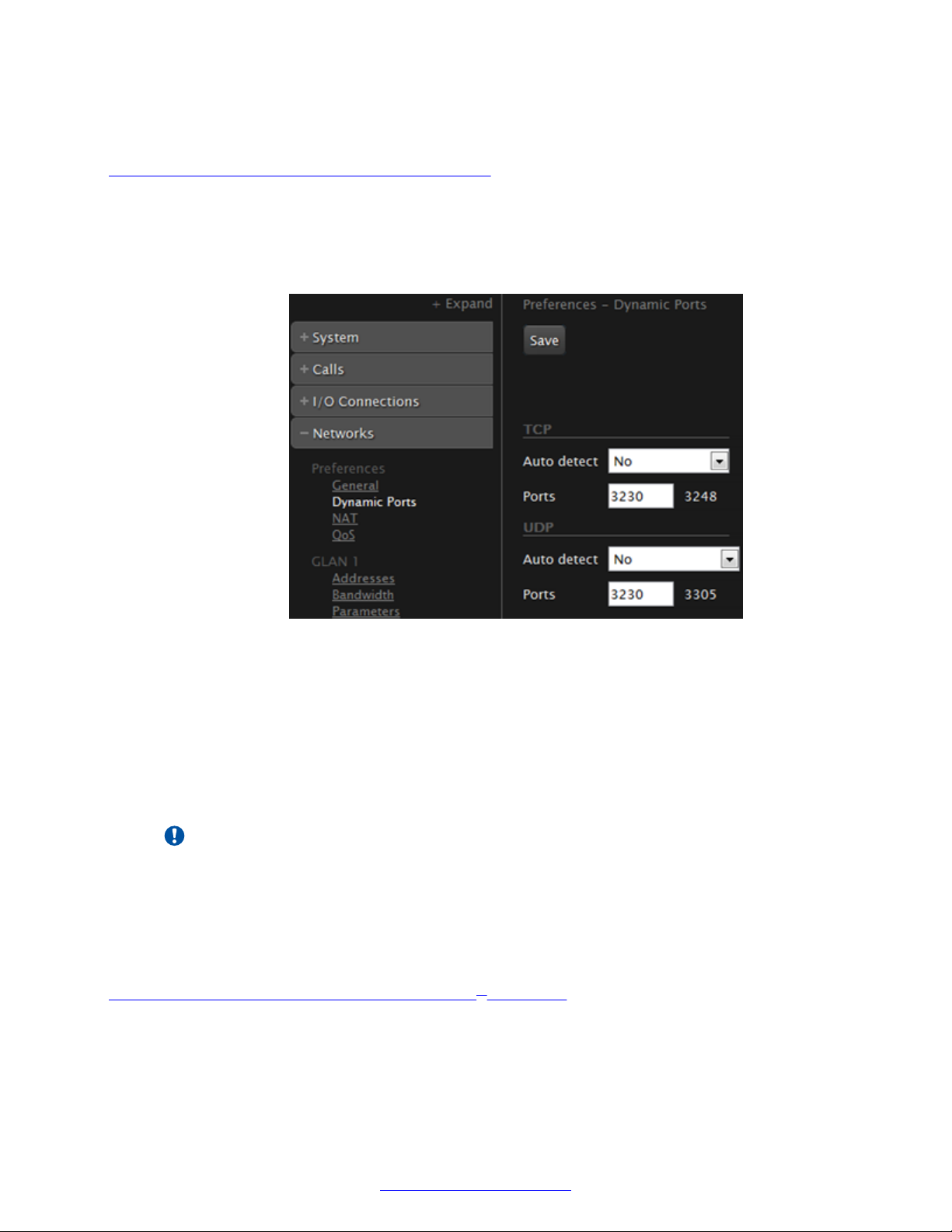
Implementing Port Security for the Avaya Scopia® XT Series
Before you begin
If configuring from the endpoint, you must first enable advanced configuration, as described in
Enabling Advanced Maintenance on the XT Series on page 112.
Procedure
1. Access the port settings. From the XT Series web interface, select Administrator
Settings > Networks > Preferences > Dynamic Ports. From the endpoint's main menu,
select Configure > Advanced > Networks > Preferences > Dynamic Ports.
Figure 19: Configuring the TCP or UDP port range from the web interface
2. Define how the XT Series assigns ports by selecting one of the following from Auto detect:
• No: The XT Codec Unit uses the range of dynamic ports indicated and allows you to
define the base port (default and recommended setting).
• Yes: The XT Codec Unit assigns ports randomly, and you cannot define the base port.
3. If you selected No in the Auto detect list, you can modify the TCP or UDP base port in the
Ports field.
Important:
You can configure the base port to any value between 1024-65535. The number of ports
is calculated automatically by the system, depending on whether you have an MCU
license and its type.
4. From the web interface only, select Save.
Related Links
Implementing Port Security for the Avaya Scopia® XT Series on page 31
April 2015 Avaya Scopia® XT Series Deployment Guide 41
Comments? [email protected]
Page 42

Chapter 4: Setting Up the XT Series
Hardware
These sections describe how to connect the XT Series to the network and other hardware
components like monitors, cameras and microphones.
Related Links
Planning the Optimal Room Setup on page 42
Connecting Avaya Scopia® XT Series to the Network on page 46
Connecting Monitors to the XT Series on page 47
Connecting Cameras or DVD players on page 48
Connecting Microphones and Speakers to the XT Series on page 59
Connecting a Computer to the XT Series on page 65
Planning the Optimal Room Setup
Follow the recommended guidelines described in this section when setting up a room with an Avaya
Scopia® XT Series endpoint.
42 Avaya Scopia
®
XT Series Deployment Guide April 2015
Comments? [email protected]
Page 43
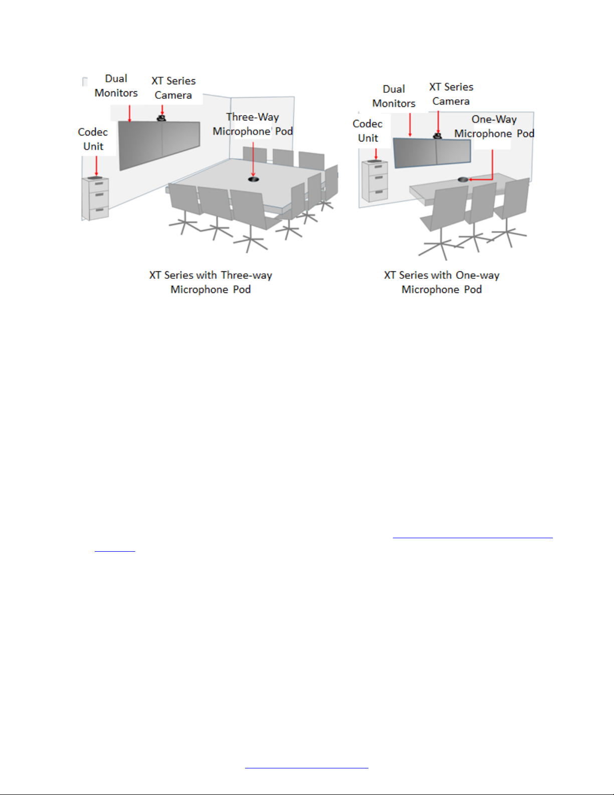
Figure 20: Optimal Room Setup
Planning the Optimal Room Setup
• Walls and furniture
Choose a plain neutral wall color. Avoid white walls as they increase the back light, causing
cameras to reduce exposure and introducing a silhouetting effect. Avoid glass walls, or
patterned and textured walls as they may cause visual disturbances.
The room should be well and uniformly lit, with a brightness of at least 300 lux, avoiding a
mixture of natural and artificial light. Light should come from the top of the conference table, the
front and the rear (for depth of field). If the only light is from the ceiling, it should be gentle light
and generate as little heat as possible.
Use heavy curtains with a neutral color and install carpets to reduce noise interference from
resonance with hard surfaces in the room.
The room should be air-conditioned to avoid the XT Codec Unit activating its fan.
• Camera positions
Ensure the camera's view captures all the seats in the room (Figure 21: Camera scope covers
all seats on page 44).
April 2015 Avaya Scopia® XT Series Deployment Guide 43
Comments? [email protected]
Page 44
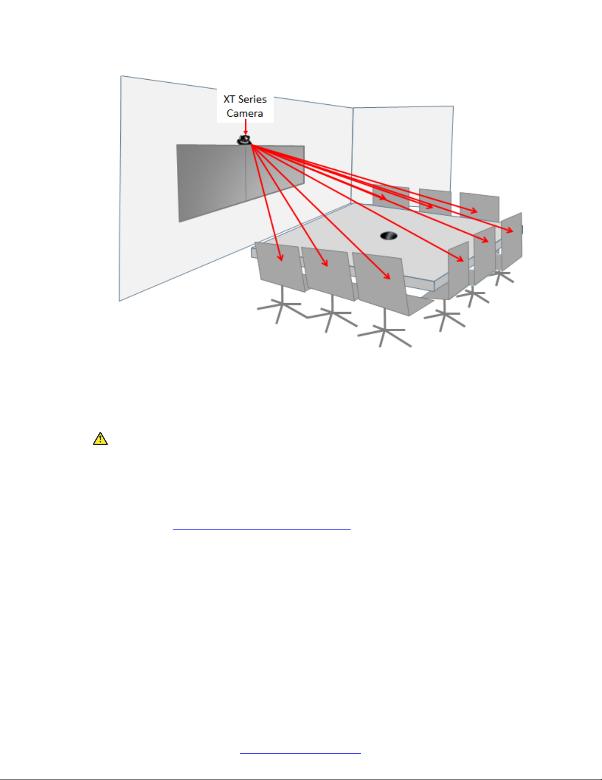
Setting Up the XT Series Hardware
Figure 21: Camera scope covers all seats
All cameras should be at a height to ensure eye contact between local and remote participants.
Try positioning the camera between the two monitors either directly above or below them, at a
distance which captures all the seats.
Caution:
Do not place the camera on top of the XT Codec Unit. It can cause the system to overheat.
Place chairs so that you and other participants appear in full frame of the cameras, in the
middle of the monitors.
For larger rooms, a single XT Series can manage more than one camera. For more
information, see Connecting Cameras or DVD players on page 48.
• Microphone positions
Place the Microphone Pod at the center of the table, in front of the participants.
If you deploy the One-way Microphone Pod, note it has a limited three meter 180° range, so be
sure to place all participants on one side of the microphone. The Three-way Microphone Pod
picks up sound up to three meters away at all angles (360°).
44 Avaya Scopia
®
XT Series Deployment Guide April 2015
Comments? [email protected]
Page 45
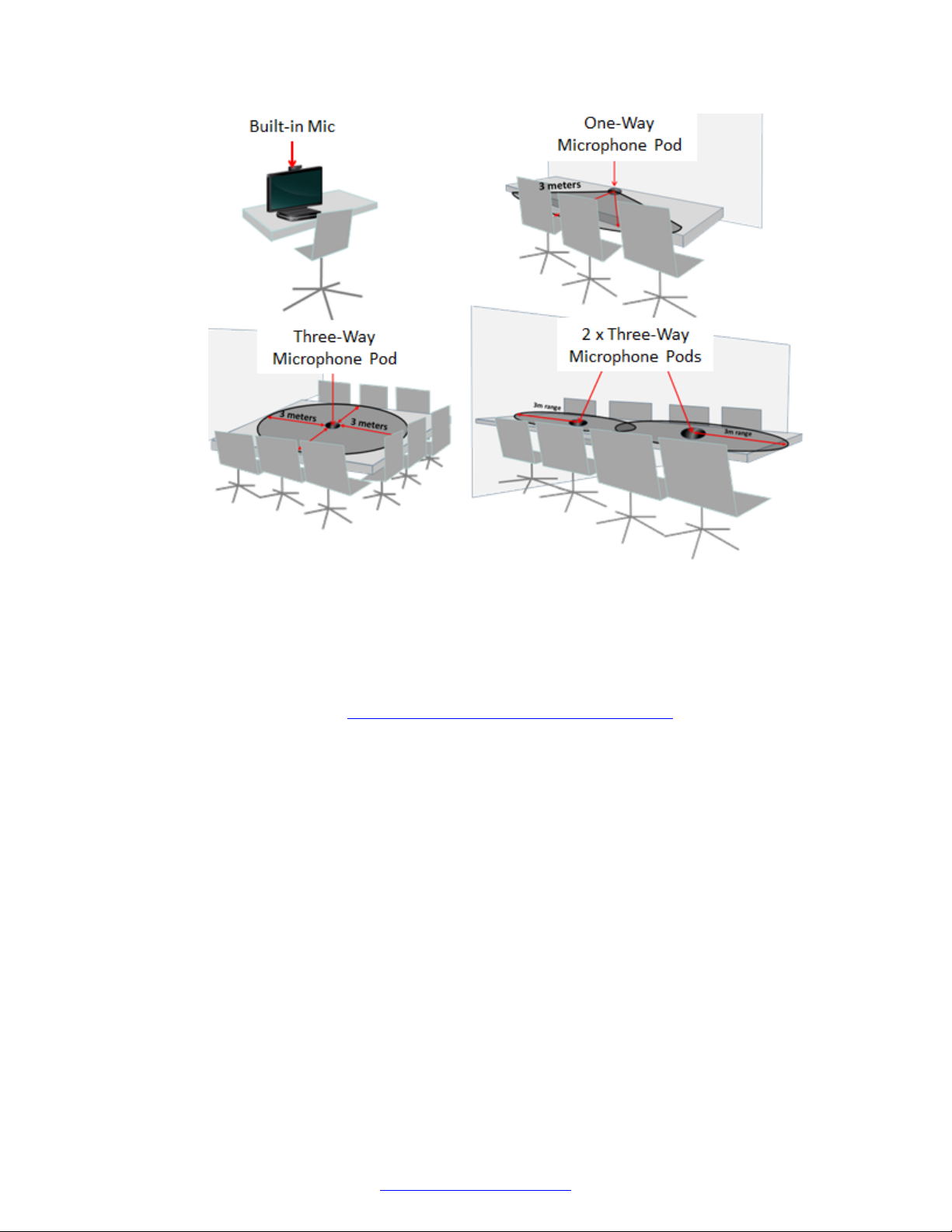
Planning the Optimal Room Setup
Figure 22: Placing the Microphone Pods
Position the Microphone Pod as far as possible from loudspeakers and other noise sources.
Do not place paper or other objects in front of the Microphone Pod.
For large conference rooms, you can deploy two Microphone Pods, distributed evenly on the
table. In very large rooms, consider an audio mixer to add as many microphones as needed.
For more information, see Choosing a Microphone for Your XT Series on page 59.
• Position of the XT Codec Unit
Place the XT Codec Unit on a horizontal surface which stands firmly on its base. The surface
must be dry and free of dust, oil and other residues.
Position the XT Codec Unit and the camera so that their front panel infra-red (IR) sensors are
visible by someone holding the XT Remote Control Unit. If the XT Codec Unit is in a cabinet,
the XT Remote Control Unit sends to the main camera's sensor which relays to the XT Codec
Unit.
Ensure the infra-red sensors do not face sunlight or inverter fluorescent lamps.
Place the XT Codec Unit anywhere within a five meters reach of the camera cables.
Leave enough space around the XT Codec Unit for air circulation and for connecting cables
easily.
• Configuring the monitors
Configure the monitors while the cameras are in self-view mode to ensure the correct levels of
contract, brightness and sharpness.
April 2015 Avaya Scopia® XT Series Deployment Guide 45
Comments? [email protected]
Page 46

Setting Up the XT Series Hardware
If the monitor has visual preset modes, choose Cinema or Movie as the best choice for
videoconferencing.
If using the monitor's speakers, enable the monitor's noise reduction setting if available. See
the monitor's documentation for details.
Related Links
Setting Up the XT Series Hardware on page 42
Connecting Avaya Scopia® XT Series to the Network
About this task
Your Avaya Scopia® XT Series comes with two network ports (dual-NIC), where each is a GLAN or
gigabit LAN port, operating at speeds of 10 or 100 or 1000 megabits per second (Mbps).
Connect the network cable to the GLAN1
port.
If required, you can enable GLAN2 with a license to use both network ports (see Activating the
XT Series and its Optional Features on page 78).
For example, a small business can use the XT Series as a firewall traversal system (see Planning
NAT and Firewall Traversal with Avaya Scopia® XT Series on page 27), where the XT Series hosts
a call on its built-in MCU, and endpoints from both the public and private networks can access the
same videoconference. Connect one network port to the public network and the other to the private
network.
Another example of dual-NIC usage is when a large organization routes video on a higher
performance network, while routing the API control of the XT Series on another network.
46 Avaya Scopia
®
XT Series Deployment Guide April 2015
Comments? [email protected]
Page 47
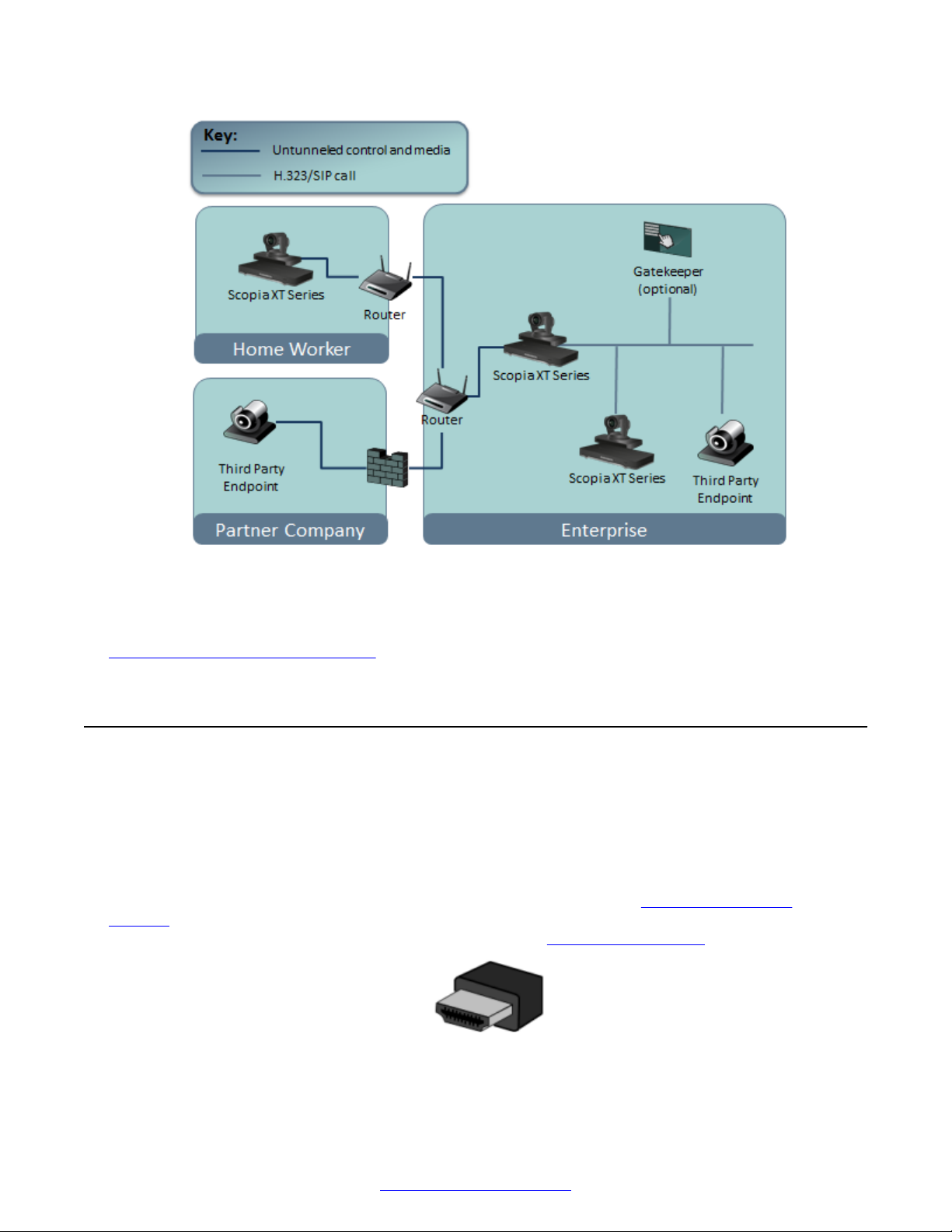
Connecting Monitors to the XT Series
Figure 23: Small business topology using both network ports to connect to a private and public
network
Related Links
Setting Up the XT Series Hardware on page 42
Connecting Monitors to the XT Series
About this task
Connect one or two monitors to the Avaya Scopia® XT Series to use it as a videoconferencing
endpoint, and to view the interface (menus) of the endpoint itself. Use the XT Remote Control Unit
to navigate these menus.
Each monitor is connected with an HDMI cable which can transmit both video and audio. You can
calibrate the monitor image position using the quick setup wizard (see
Position on page 86). To configure the advanced monitor settings like the resolution of one or two
monitors and the video layouts of embedded images, see
Configuring Monitors on page 96.
Adjusting the Image
Figure 24: HDMI cable
April 2015 Avaya Scopia® XT Series Deployment Guide 47
Comments? [email protected]
Page 48
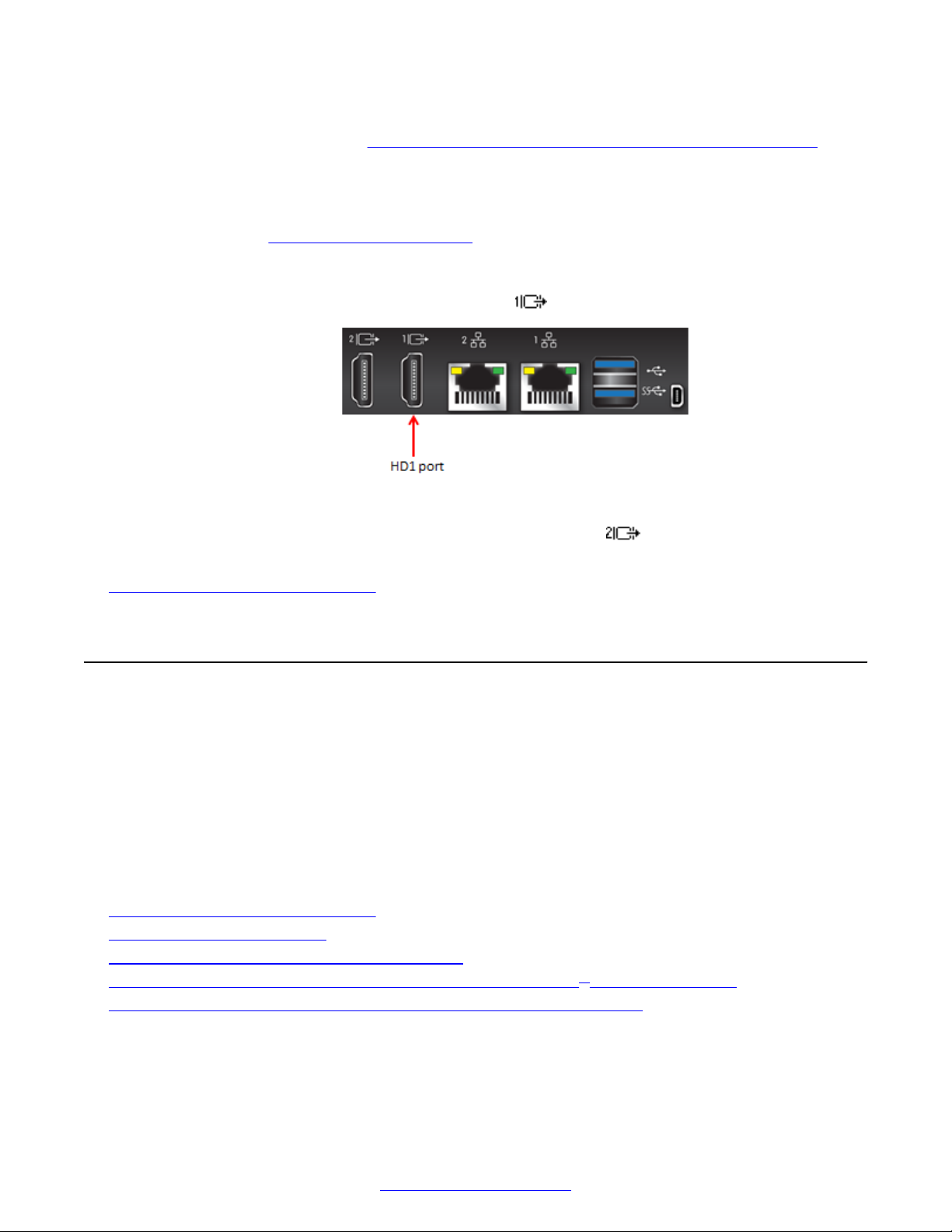
Setting Up the XT Series Hardware
The endpoint's sound is routed to one of the monitor's loudspeakers. You can customize the sound
with amplifiers and speakers (see Connecting Headphones or an Amplifier with Loudspeakers on
page 64).
Before you begin
To connect two monitors on the Avaya Scopia® XT4300, you need to first enable the license for a
second monitor (see
Connecting Monitors to the on page 47).
Procedure
1.
Connect the monitor's HDMI cable to the HD1 port on the XT Codec Unit:
Figure 25: Connecting a monitor to the XT Series
2.
(Optional) Connect the second monitor's cable to the HD2 port on the XT Codec Unit.
Related Links
Setting Up the XT Series Hardware on page 42
Connecting Cameras or DVD players
You can connect one or more PTZ (pan, tilt, zoom) cameras directly to the Avaya Scopia® XT
Series, and also connect a DVD player or media player to the DVI port. On the XT7000 Series and
XT5000 Series, you can also connect multiple cameras and HDMI devices via the Scopia® XT
Camera Switch.
You can also connect a USB camera, like the Logitech C290 Webcam, to the upper USB port on the
XT Series. The Scopia® XT Executive already has a built-in USB camera, and you can connect a
PTZ camera to use instead of the USB camera.
Related Links
Setting Up the XT Series Hardware on page 42
Connecting the PTZ Camera on page 49
Connecting an Additional PTZ Camera Directly on page 51
Connecting Multiple HDMI Devices or Cameras via the Scopia® XT Camera Switch on page 54
Connecting a DVD or Blu-ray Player or Other Analog Video Equipment on page 58
48 Avaya Scopia
®
XT Series Deployment Guide April 2015
Comments? [email protected]
Page 49

Connecting Cameras or DVD players
Connecting the PTZ Camera
About this task
This procedure describes how to connect the main PTZ camera to the Avaya Scopia® XT Series.
The XT7000 Series and the XT5000 Series use the XT Premium Camera. The XT4300 uses the XT
Flex Camera, while the XT4200 uses the XT Standard II Camera.
For details about the camera's capabilities, see Technical Specifications on page 18. For more
information about the room setup, see
Procedure
1. Place the camera in a position to ensure eye contact between local and remote participants.
If the XT Codec Unit is housed in a cabinet, the XT Remote Control Unit sends the signal to
the infra-red receiver of the main camera to relay messages to the XT Codec Unit. In this
case, configure the camera settings so the camera's power is always on (see Configuring
Cameras on page 100).
Try positioning the camera between the two monitors either directly above or below them, at
a distance which captures all the seats.
Planning the Optimal Room Setup on page 42.
Caution:
Do not place the camera on top of the XT Codec Unit. It can cause the system to
overheat.
2. Remove the camera stabilizing cartons before connecting the camera to avoid damage to
the system.
3. Insert the following connectors on the camera cable to the ports on the back of the camera,
as shown in Figure 26: Connecting cables to the back of the camera on page 50:
• The DVI connector to the DVI socket
• The 8-pin connector to the IN (RS232C) socket
• The power connector to the DC IN 12V socket
April 2015 Avaya Scopia® XT Series Deployment Guide 49
Comments? [email protected]
Page 50
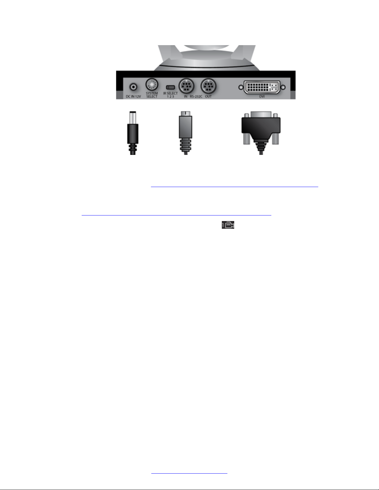
Setting Up the XT Series Hardware
Figure 26: Connecting cables to the back of the camera
4. With the camera turned off, set the System Select switch on back of the camera to 7 using a
slotted 2.5 mm screwdriver (
page 50).
Figure 26: Connecting cables to the back of the camera on
5. Insert the two connectors on the other end of the camera cable to the ports on the XT Codec
Unit (Figure 27: Connecting the camera cables to the XT Codec Unit on page 51).
For the XT7000 Series, use the ports located under on the XT Codec Unit.
• Connect the HDMI plug to the vertical socket.
• Connect the other plug (power) to the horizontal socket.
We recommend keeping the DVI socket available for a computer connection (for example, to
share content in a videoconference).
50 Avaya Scopia
®
XT Series Deployment Guide April 2015
Comments? [email protected]
Page 51
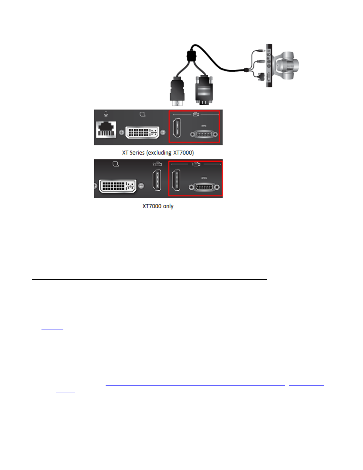
Connecting Cameras or DVD players
Figure 27: Connecting the camera cables to the XT Codec Unit
6. Enable the HD1 camera and configure its settings, as described in
Configuring Cameras on
page 100.
Related Links
Connecting Cameras or DVD players on page 48
Connecting an Additional PTZ Camera Directly
About this task
You can connect an additional PTZ (pan, tilt and zoom) camera to the XT Series for large room
setups, when one camera does not cover enough area (
Directly on page 52):
• For all XT Series models, you can connect it directly to the DVI port on the XT Codec Unit, as
described below.
• For the XT7000 Series only, you can also connect it to the HDMI 2 port on the XT Codec Unit
(recommended), as described below.
• For the XT7000 Series and XT5000 Series, you can connect multiple cameras via the Scopia
XT Camera Switch (purchased separately), which keeps the DVI port free to add a computer or
DVD player (see
Connecting Multiple HDMI Devices or Cameras via the Scopia® XT Camera
Switch on page 54).
Connecting an Additional PTZ Camera
®
The additional PTZ camera kit contains the camera itself, remote control, power supply, HDMI to
DVI adapter, five-meter DVI-HDMI cable, and a ceiling mount kit.
April 2015 Avaya Scopia® XT Series Deployment Guide 51
Comments? [email protected]
Page 52
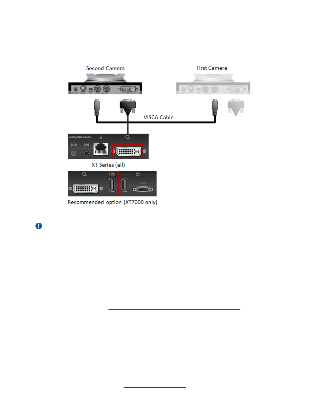
Setting Up the XT Series Hardware
It also includes a 10-meter VISCA cross cable, enabling you to control both cameras with the same
XT Remote Control Unit on the XT5000 Series only, by connecting a VISCA cross cable between
the cameras. This disables the extra remote control. VISCA is a standard protocol to control PTZ
cameras.
Figure 28: Connecting an additional camera directly to the XT Series
Important:
Connecting cameras with a VISCA cable requires that both are exactly the same model.
Before you begin
For larger room setups, if you need a longer HDMI cable than the supplied five-meter DVI-HDMI
cable, be sure to add HDMI repeaters. For 1080p at 60fps, add a repeater every five meters. For
1080p at 30fps or 720p at 60fps, add a repeater every 10 meters. Compatible HDMI repeaters are
listed in Third-Party Accessories for Avaya Scopia® XT Series.
To control both cameras of the same model using one XT Remote Control Unit (on the XT7000
Series and XT5000 Series only), use the supplied 10-meter VISCA cross cable, or for large room
setups, buy a longer third-party cable, or create your own. The RS232 cable should be up to 15-20
meters long, where both ends have an 8-pin mini-DIN male connector. To create your own cable,
connect the pins as shown in
Figure 29: Creating your own long VISCA cross cable on page 53.
52 Avaya Scopia
®
XT Series Deployment Guide April 2015
Comments? [email protected]
Page 53
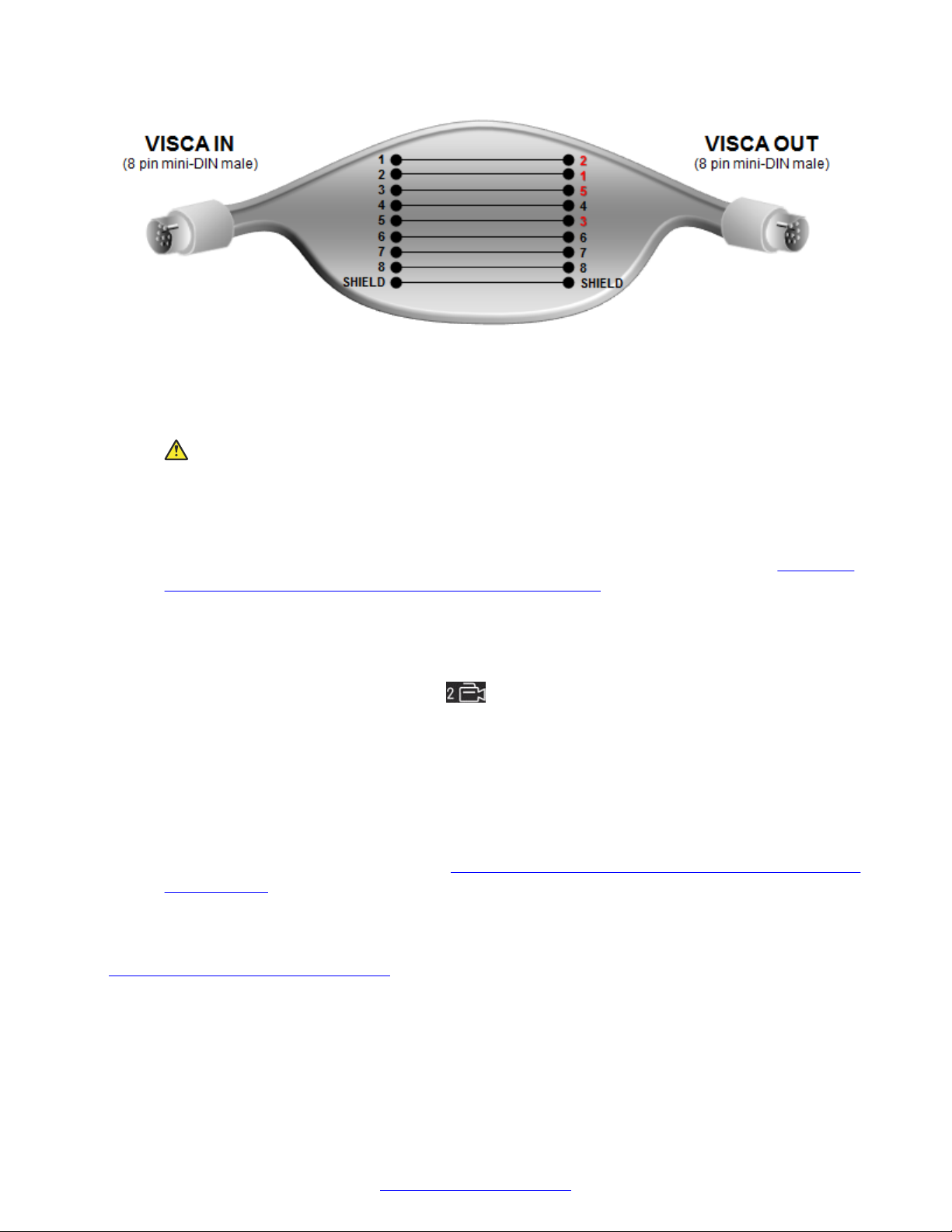
Connecting Cameras or DVD players
Figure 29: Creating your own long VISCA cross cable
Procedure
1. Remove the camera stabilizing cartons, to avoid damage to the system.
Caution:
Do not place the camera on top of the XT Codec Unit. It can cause the system to
overheat.
2. Verify the SYSTEM SELECT switch on the back panel of the new camera is set to 7.
3. Connect the DVI port on the camera to the DVI connector on the XT Codec Unit (Figure 28:
Connecting an additional camera directly to the XT Series on page 52). The system
manages it as PC content.
—Or—
For the XT7000 Series, we recommend connecting the additional camera to the HDMI 2 port
on the XT Codec Unit (located under ). This keeps the DVI port available for a computer
connection.
4. Connect the power supply cable to the DC IN connector on the camera.
5. Plug the power supply cable into a power outlet.
6. (Optional for XT7000 Series and XT5000 Series only) To control the extra camera using the
same XT Remote Control Unit, connect one end of the crossed VISCA control cable to the
additional camera's IN (RS-232C) connector. Then connect the other end to the main
camera's OUT (RS-232C) connector (
the XT Series on page 52).
7. Apply power to the camera.
Related Links
Connecting Cameras or DVD players on page 48
Figure 28: Connecting an additional camera directly to
April 2015 Avaya Scopia® XT Series Deployment Guide 53
Comments? [email protected]
Page 54

Setting Up the XT Series Hardware
Connecting Multiple HDMI Devices or Cameras via the Scopia® XT Camera Switch
About this task
You can connect a second PTZ camera to your XT Series, for large room setups. All XT Series
models can connect the extra camera directly to the DVI port. However, the XT7000 Series and
XT5000 Series can also connect it via the Scopia® XT Camera Switch which is purchased
separately. Using the switch enables multiple HDMI connections and keeps the DVI port available
for a computer or DVD player to share content. For example, you may want to zoom one camera to
focus on the speaker, and use another camera for the audience.
On the XT7000 Series only, you can connect a second camera to an extra HDMI port on the XT
Codec Unit, without using the Scopia® XT Camera Switch. Use the Scopia® XT Camera Switch
when connecting more than two cameras to the XT7000 Series.
With the Scopia® XT Camera Switch, you can connect up to four HD cameras or HDMI devices, like
a DVD or other media player. Only use cameras of the same model.
Connected cameras can be controlled from an XT7000 Series or XT5000 Series endpoint.
Important:
The Avaya Scopia® XT4000 Series, Scopia® XT Executive, and XT1200 do not support the
Scopia® XT Camera Switch.
Before you begin
Caution:
• Make sure all units are switched off when connecting or disconnecting devices.
• Always remove the camera stabilizing cartons before connecting the camera.
• Do not place a camera on top of the XT Codec Unit. It can cause the system to overheat.
Procedure
1. Install the Scopia® XT Camera Switch on a horizontal surface close to the XT Codec Unit.
The supplied cable length is 40cm (0.13ft).
2. Connect the USB and HDMI cables as follows (Figure 30: Connecting the Scopia® XT
Camera Switch to the XT Codec Unit on page 55):
• Connect one end of the HDMI cable to the OUTPUT socket on the Scopia® XT Camera
Switch and the other end to the vertical HDMI connector on the XT Codec Unit.
On the XT5000 Series, use the vertical HDMI 1 port on the XT Codec Unit (located under
).
On the XT7000 Series, use the vertical HDMI 2 port on the XT Codec Unit (located under
54 Avaya Scopia
).
®
XT Series Deployment Guide April 2015
Comments? [email protected]
Page 55
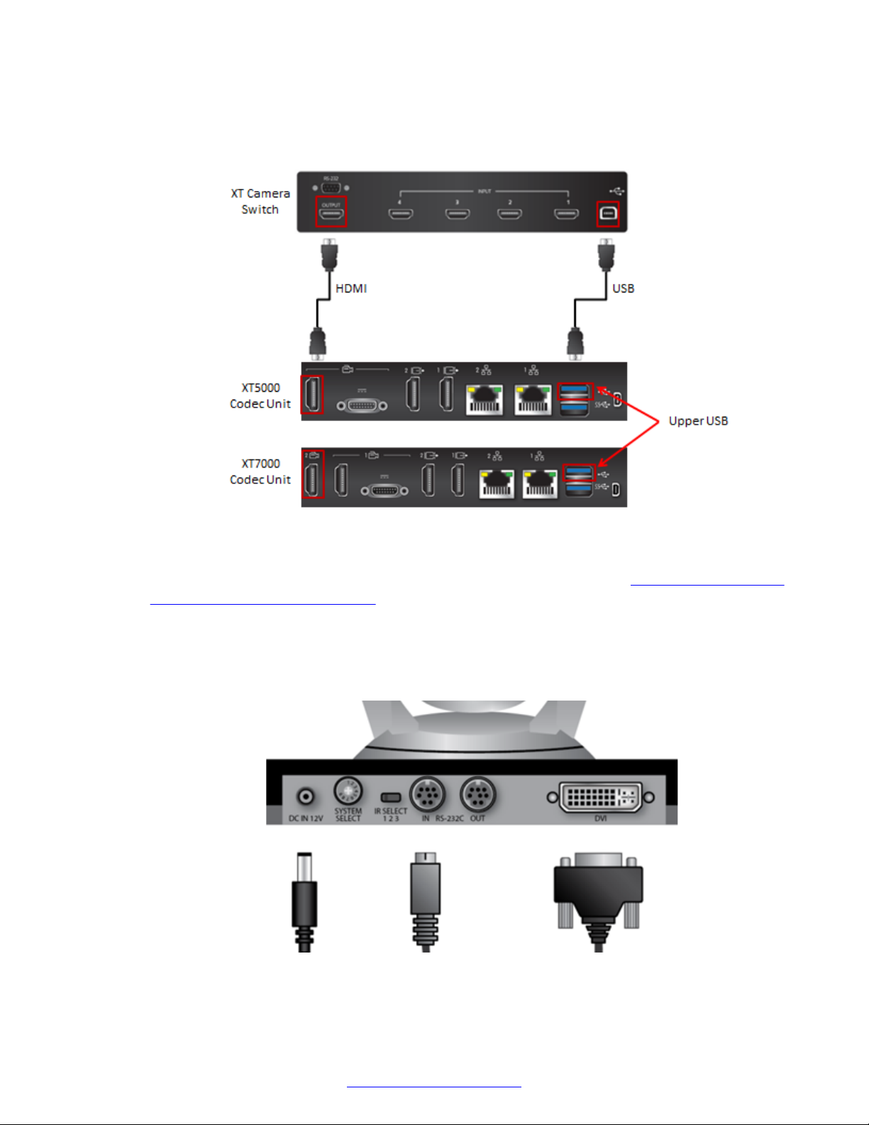
Connecting Cameras or DVD players
• Connect one end of the USB cable to the USB socket on the Scopia® XT Camera Switch
and the other end to the upper USB connector on the XT Codec Unit. This cable also
provides power to the device, so no extra power cable is required.
Figure 30: Connecting the Scopia® XT Camera Switch to the XT Codec Unit
3. Insert the three connectors of the camera cable (3 connectors on one side, 2 connectors on
the other side) to the sockets on the back of the camera, as shown in
Figure 26: Connecting
cables to the back of the camera on page 50:
• The DVI connector to the DVI socket
• The 8-pin connector to the IN RS232C socket
• The power connector to the DC IN 12V socket
Figure 31: Connecting cables to the back of the camera
April 2015 Avaya Scopia® XT Series Deployment Guide 55
Comments? [email protected]
Page 56
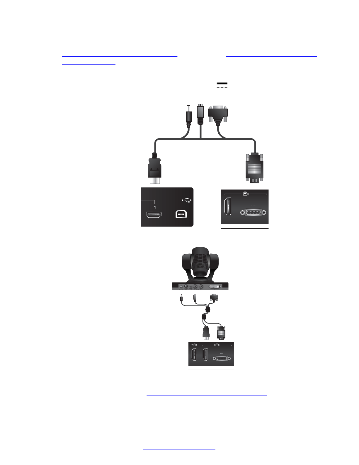
Setting Up the XT Series Hardware
4. Attach the two connectors on the other end of the camera cable as shown in Figure 32:
Connecting cables to the XT5000 Series on page 56 and Figure 33: Connecting cables to
the XT7000 Series on page 56:
a. The HDMI connector to the HDMI socket labeled 1 on the Scopia® XT Camera Switch.
b.
The connector for power and serial control to the
Codec Unit.
Figure 32: Connecting cables to the XT5000 Series
horizontal HDMI socket on the XT
5. Connect the second camera (
a. Connect the 10-meter VISCA crossed cable supplied with the camera kit.
56 Avaya Scopia
Figure 33: Connecting cables to the XT7000 Series
Figure 34: Connecting the second camera on page 57):
®
XT Series Deployment Guide April 2015
Comments? [email protected]
Page 57
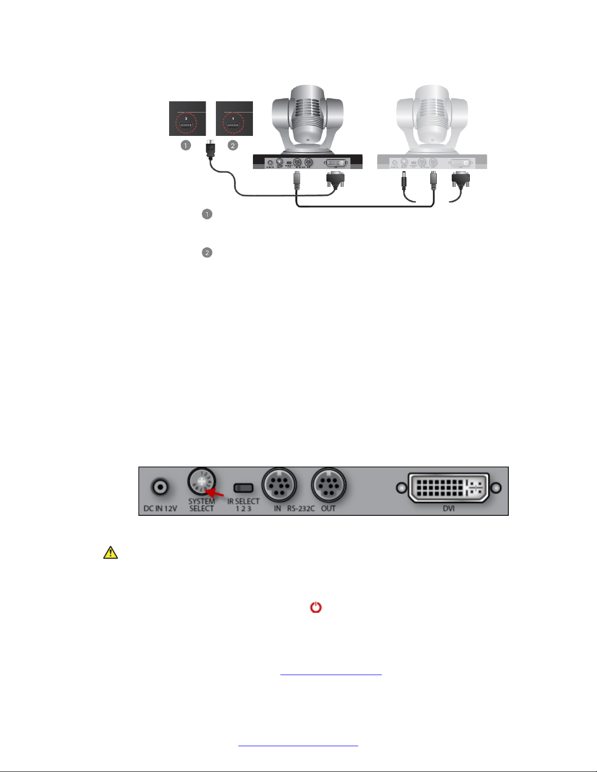
XT Camera Switch
Connected to XT5000
XT Camera Switch
Connected to XT7000
Second Camera
First Camera
Connecting Cameras or DVD players
Figure 34: Connecting the second camera
• Attach one end of the VISCA control cable to the IN RS-232C connector on the
second camera.
• Attach the other end to the OUT RS-232C connector on the previous camera.
b. Connect the DVI-HDMI cable:
• Attach the DVI connector to the DVI socket on the second camera.
• Attach the HDMI connector to the HDMI socket labeled 2 on the Scopia® XT Camera
Switch.
6. If required, repeat the above step for a third or fourth HDMI device.
7. Check that the SYSTEM SELECT switch on the back panel of each camera is set to 7:
Figure 35: Checking the SYSTEM SELECT switch
Caution:
To adjust the switch, you must first turn the camera off. Adjust it using a slotted 2.5 mm
screwdriver.
8.
Turn on the XT Codec Unit by pressing the power key on the XT Remote Control Unit.
This also turns on the Scopia® XT Camera Switch.
April 2015 Avaya Scopia® XT Series Deployment Guide 57
9. Connect one end of the power supply cable to the DC IN 12V connector on each camera,
and the other end into one of the power sockets on the wall.
10. Configure the cameras' settings (see
Comments? [email protected]
Configuring Cameras on page 100.)
Page 58
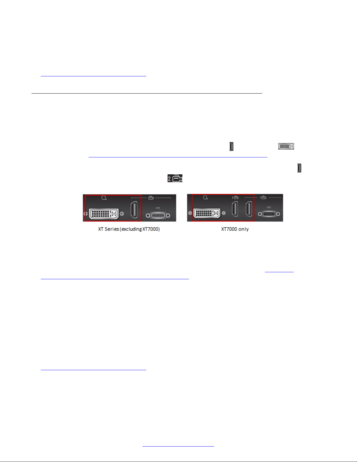
Setting Up the XT Series Hardware
If required, connect a DVD or HDMI media player to a port on the Scopia® XT Camera
Switch.
Related Links
Connecting Cameras or DVD players on page 48
Connecting a DVD or Blu-ray Player or Other Analog Video Equipment
About this task
You can add a DVD or Blu-ray player to the Avaya Scopia® XT Series to share its content during a
videoconference by connecting it to either the vertical camera port
Codec Unit (see Figure 36: Connecting a DVD player or digital-analog converter on page 58).
On the XT7000 Series only, you have the option of connecting to one of two vertical HDMI
your HDMI 2 port is available (located under
DVI port available for a computer connection.
Figure 36: Connecting a DVD player or digital-analog converter
You can also add an analog camera or other analog video equipment, such as legacy composite
video or component video media devices, by connecting it to an analog-digital converter which, in
turn, is connected to the same camera or DVI ports on the XT Codec Unit (see Figure 36:
Connecting a DVD player or digital-analog converter on page 58). For information on the converters
tested with the XT Series, see Third-Party Accessories for Avaya Scopia® XT Series. These type of
media devices include VCR players, DVD players, and cameras.
The XT Series supports digital content protection. If the XT Codec Unit detects that non-compliant
devices are attached to one of the HD CAM inputs, the video is locked.
), we recommend using this port and keeping the
or the DVI port on the XT
ports. If
• You can only view digitally protected content on a device that supports High-bandwidth Digital
Content Protection (HDCP).
• You cannot view digitally protected content on a device that copies HDCP content.
• You cannot send digitally protected content to non-HDCP devices.
Related Links
Connecting Cameras or DVD players on page 48
58 Avaya Scopia
®
XT Series Deployment Guide April 2015
Comments? [email protected]
Page 59
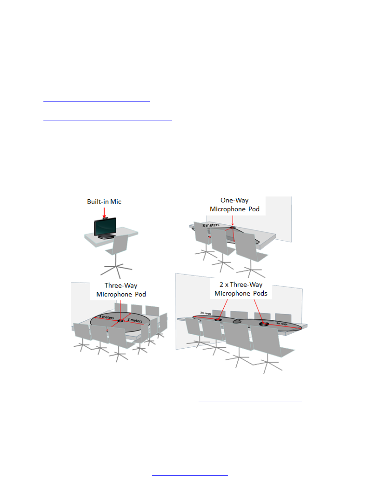
Connecting Microphones and Speakers to the XT Series
Connecting Microphones and Speakers to the XT Series
These sections describe how to connect audio equipment, such as the XT Digital Microphone Array
Pod, to the XT Codec Unit:
Related Links
Setting Up the XT Series Hardware on page 42
Choosing a Microphone for Your XT Series on page 59
Connecting a Microphone to the XT Series on page 62
Connecting Headphones or an Amplifier with Loudspeakers on page 64
Choosing a Microphone for Your XT Series
This section provides an overview of the different types of microphones which are shipped with the
various models in the Avaya Scopia® XT Series. You can add more microphones to your XT Series
depending on the room setup.
Figure 37: Choosing the microphone for your XT Series
To determine the best microphone positioning, see Planning the Optimal Room Setup on page 42.
When deciding on the microphone best suited for the meeting room, consider the following factors:
• A larger room requires more microphones. Position the microphones to ensure all participants
are within range.
April 2015 Avaya Scopia® XT Series Deployment Guide 59
Comments? [email protected]
Page 60
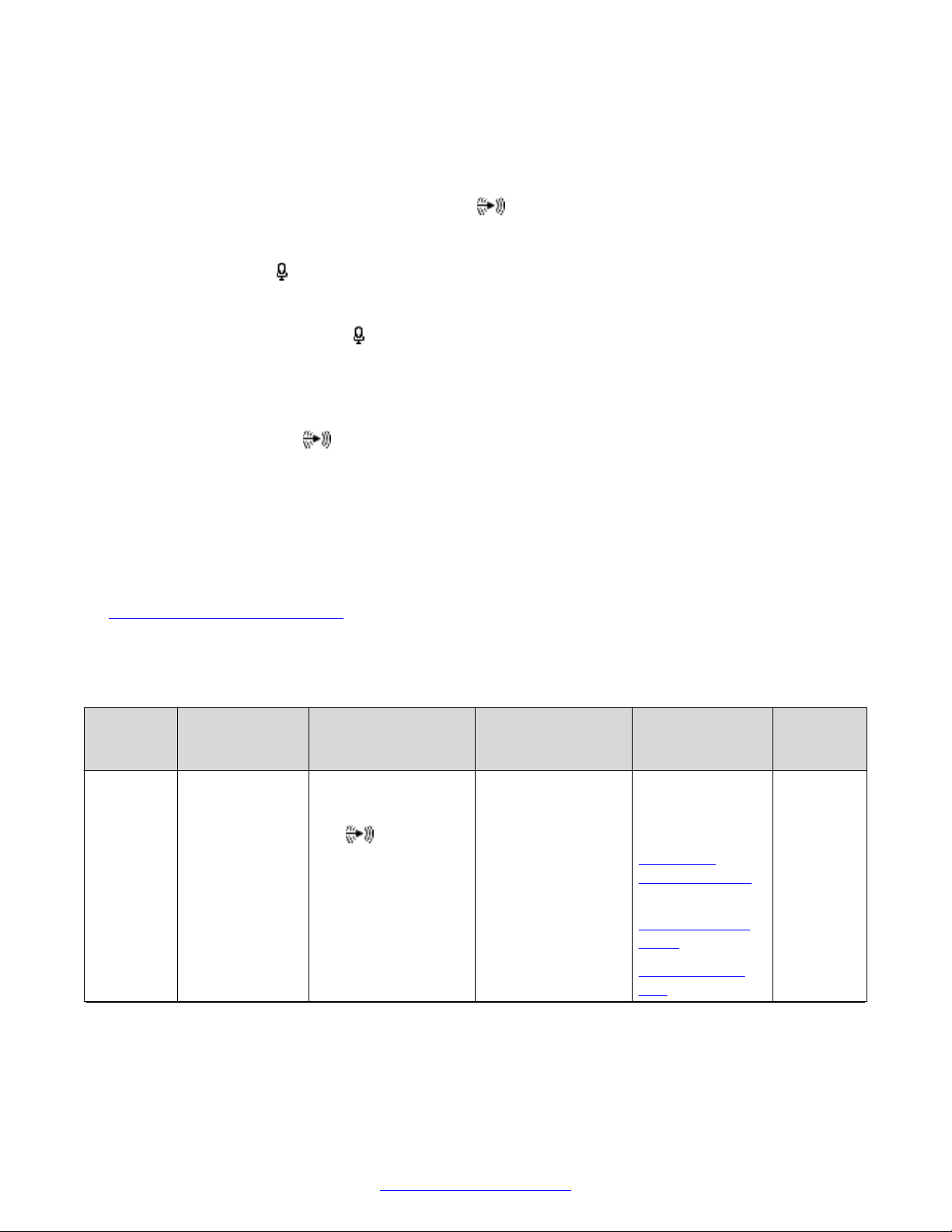
Setting Up the XT Series Hardware
• A digital microphone brings higher quality sound, and are usually connected via optical cables
which can be deployed over longer distances than analog (copper) wires.
• For more complex audio setups, you can connect the XT Series to an audio mixer.
•
The XT Codec Unit uses the same audio in port for third-party digital microphone, analog
microphones, line input, and computer audio, so you must choose between them. You can free
this port when you use the digital three-way XT Digital Microphone Array Pod, which uses its
own microphone
port, or by using an audio mixer.
There are several connections available to input audio to the XT Series:
•
The dedicated microphone
port is for the digital Three-way Microphone Pod. The XT5000
Series can support two of these microphones daisy-chained.
• The USB port is used for USB headsets, or for a USB camera with a built-in microphone (lower
USB only).
•
The audio input port
is for:
- The analog One-way Microphone Pod or any other analog microphone with a 3.5mm jack.
- A third-party digital microphone with a mini-TOSlink connector.
- Audio mixers like those from Clear One. An audio mixer connects multiple microphones (or
other audio inputs) to generate a single audio stream.
- A computer audio-out connection or line audio connection.
Table 8: Types of microphones on page 60 describes the most common types of microphones
used with an Avaya Scopia® XT Series.
Table 8: Types of microphones
Type of
Microphon
e
USB
Camera
with Built-in
Microphon
e, or USB
headset
Optimal Room
Size
Personal
endpoint for
close proximity
to speaker
Advantages Disadvantages Microphone
Specifications
Cost-effective.
Frees the audio input
port for computer
audio input.
Short range,
suitable for a single
participant only.
Digital audio
Supported
headsets:
Plantronics
Voyager Pro UC
Wireless
Plantronics Savi
W440
Jabra Pro 9450
Duo
Table continues…
Typically
Used With
Scopia® XT
Executive
60 Avaya Scopia
®
XT Series Deployment Guide April 2015
Comments? [email protected]
Page 61
Connecting Microphones and Speakers to the XT Series
Type of
Microphon
e
One-way
Microphon
e Pod
Three-way
XT Digital
Microphon
e Array
Pod
Third-party
Digital
Microphon
e
Third-party
Analog
Microphon
e
Multiple
Microphon
es with
Optimal Room
Size
Small meeting
rooms (up to
4x4m)
Large meeting
rooms (up to
6x6m)
For very large
rooms (up to
12x6m), use two
three-way
Microphone
Pods. You
cannot use more
than two
Microphone
Pods for one
system. (XT5000
only)
Large meeting
rooms,
positioned
anywhere.
Cables can run
for longer
distances.
Large meeting
rooms,
positioned up to
a few meters
from the XT
Codec Unit.
Very large
meeting rooms
Advantages Disadvantages Microphone
Specifications
Multiple participants
can be positioned up
to three meters away
on one side of the
mic.
Cost-effective
Captures more
background noise
than the three-way
Microphone Pod
Captures audio only
from one side
Analog audio
One side (180º
range)
3 meters (about
10 feet)
When connected,
you cannot transmit
PC audio
Range extends three
meters on all sides of
each microphone for
complete coverage.
Advanced beam
Higher cost. Digital
360º coverage
3 meters range
(about 10 feet)
forming technology
isolates the active
speaker from
background noise.
Superb audio quality.
When connected
directly to the XT
Codec Unit, you can
also transmit PC
audio.
Position freely due to
optical cables.
High quality audio.
Higher cost.
When directly
connected to the XT
Series, you cannot
Depends on the
specifications of
the third-party
microphone
transmit PC audio.
Position for lecturer or
other room setup.
Cost-effective
Requires careful
positioning
depending on its
specifications.
Depends on the
specifications of
the third-party
microphone
When directly
connected to the XT
Series, you cannot
transmit PC audio
Comprehensive
coverage
Higher cost Depends on the
specifications of
the third-party
Typically
Used With
Avaya
Scopia
®
XT4000
Series
Avaya
Scopia
®
XT5000
Can be
added to
any XT
Series
model.
Can be
added to
any XT
Series
model.
Avaya
Scopia
®
XT5000
Table continues…
April 2015 Avaya Scopia® XT Series Deployment Guide 61
Comments? [email protected]
Page 62

Setting Up the XT Series Hardware
Type of
Microphon
e
Audio
Mixer
Optimal Room
Size
Advantages Disadvantages Microphone
Specifications
When connected, you
can also transmit PC
audio
Separate echo
canceling
configuration
microphones and
audio mixer
Typically
Used With
Related Links
Connecting Microphones and Speakers to the XT Series on page 59
Connecting a Microphone to the XT Series
About this task
Select the microphones best suited to your deployment (see
Series on page 59), and ensure all participants are seated within the range of one of the
microphones. To determine the best microphone positioning, see Planning the Optimal Room
Setup on page 42.
More complex setups, like setting up an auditorium or mixing different types of microphones, may
require an audio mixer (for example Clear One mixers). An audio mixer connects multiple
microphones (or other audio inputs) to generate a single audio stream. Using an audio mixer
requires you disable echo-cancellation on the XT Series (see
page 104) and then enable it either on the audio mixer, or (ideally) on each microphone. The audio
mixer must have either an analog audio I/O (mini jack 3.5”) connector or a digital optical (miniTOSlink) connector.
Choosing a Microphone for Your XT
Configuring Microphones on
The Scopia® XT Executive uses the microphone embedded in the camera by default. If you connect
an additional microphone, the embedded microphone is disabled.
Procedure
1. Connect a microphone to the XT Codec Unit as follows:
•
The dedicated microphone
XT5000 Series can support two of these microphones daisy-chained.
• The USB port is used for USB headsets, or for a USB camera with a built-in microphone
(lower USB only).
•
The audio input port
- The analog One-way Microphone Pod or any other analog microphone with a 3.5mm
jack.
- A third-party digital microphone with a mini-TOSlink connector.
- Audio mixers like those from Clear One. An audio mixer connects multiple microphones
(or other audio inputs) to generate a single audio stream.
- A computer audio-out connection or line audio connection.
port is for the digital Three-way Microphone Pod. The
is for:
62 Avaya Scopia
®
XT Series Deployment Guide April 2015
Comments? [email protected]
Page 63
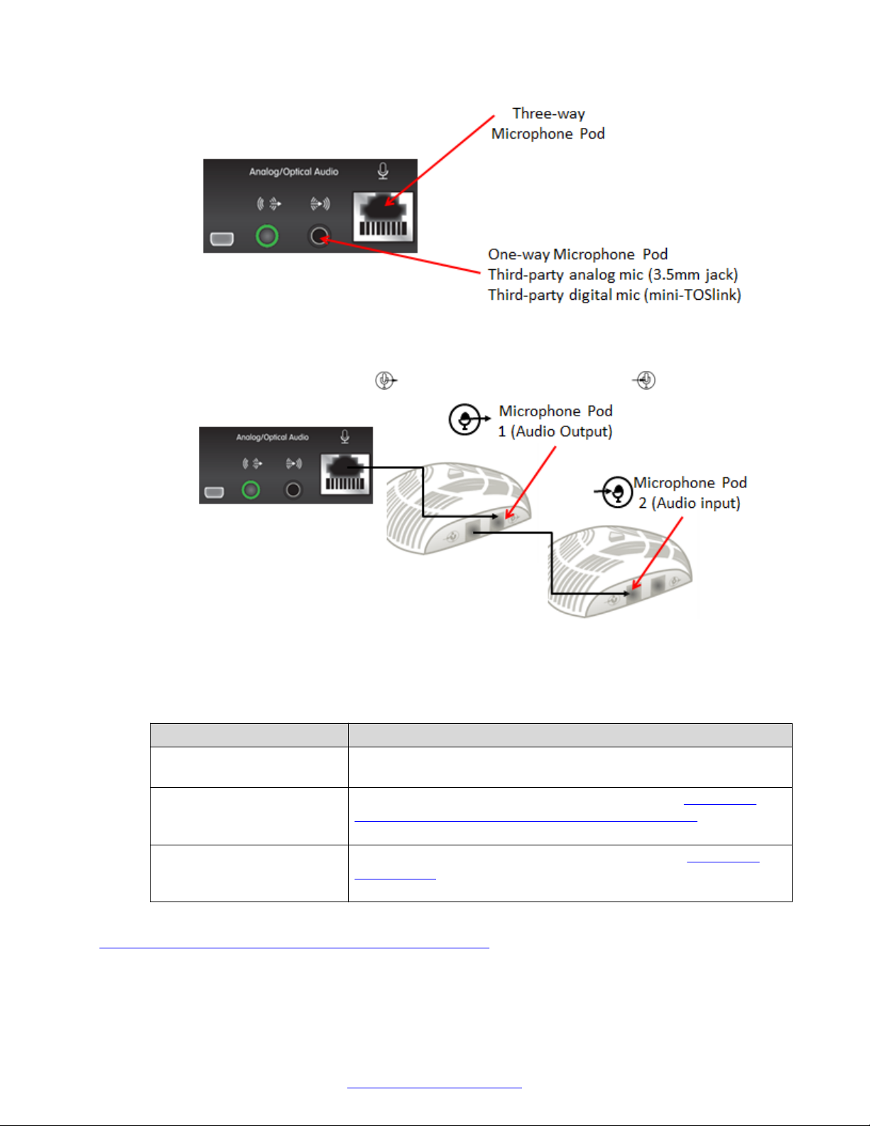
Connecting Microphones and Speakers to the XT Series
Figure 38: Connecting a microphone to the XT Codec Unit
2. (Optional, only for XT5000) To daisy-chain a second Three-way Microphone Pod, connect
the second microphone's output to the first Microphone Pod input .
Figure 39: Connecting an additional three-way Microphone Pod
3. Plan echo cancellation according to your audio setup:
Table 9: Configuring Echo Cancellation
Audio Setup Configure Echo Cancellation
Microphone Pod (One-way or
three-way)
A single third-party
microphone (without echo
cancellation)
Audio mixer Disable the XT Series built-in echo cancellation (see Configuring
XT Series enables its own echo cancellation by default.
Enable the XT Series built-in echo cancellation (see Configuring
Advanced Echo Cancellation on External Microphones on
page 137).
Microphones on page 104). You then cancel the echo either in the
audio mixer's settings, or (ideally) on each microphone.
Related Links
Connecting Microphones and Speakers to the XT Series on page 59
April 2015 Avaya Scopia® XT Series Deployment Guide 63
Comments? [email protected]
Page 64
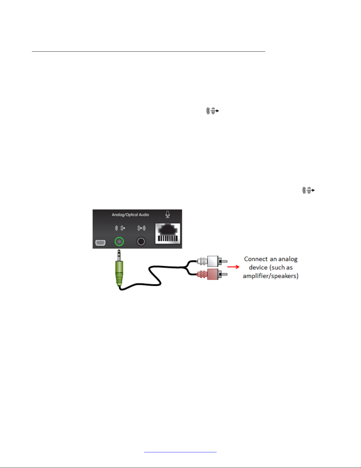
Setting Up the XT Series Hardware
Connecting Headphones or an Amplifier with Loudspeakers
About this task
By default, you hear the sound of your Avaya Scopia® XT Series from the monitors' speakers. The
monitors are connected to the XT Codec Unit using HDMI, which sends both audio and video.
To boost sound beyond the monitors' own speakers, you can add an amplifier and loudspeakers by
connecting them to the analog or digital audio output port
Alternatively, if you want to route the audio to headphones, for example when using the Scopia® XT
Executive, you can connect headphones to the monitor's audio port or the lower USB port so it cuts
off the monitor's speakers and routes sound to the headphones only.
Before you begin
If connecting an amplifier, verify you have a shielded stereo audio cable with a 3.5mm stereo audio
plug.
Procedure
of the XT Codec Unit.
1.
To boost sound, connect an amplifier with speakers directly to the audio output port
on
the XT Series.
Figure 40: Connecting external amplifier/speakers to the XT Series
2. To connect headphones to replace the monitor's speakers, connect headphones to the audio
output of the monitor.
64 Avaya Scopia
®
XT Series Deployment Guide April 2015
Comments? [email protected]
Page 65
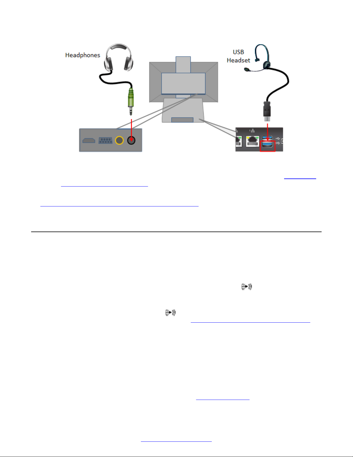
Connecting a Computer to the XT Series
Figure 41: Connecting headphones to the XT Series
Alternatively, attach a USB headset to the USB port on the XT Codec Unit (see Choosing a
Microphone for Your XT Series on page 59).
Related Links
Connecting Microphones and Speakers to the XT Series on page 59
Connecting a Computer to the XT Series
About this task
Connect a computer to share a presentation or other content with other participants. You can
display the content to participants in a local conference room, as well as to remote participants
during a call. You connect the video separately from the audio. The computer video is routed to the
DVI port on the XT Codec Unit, while the audio is routed to the audio-in
When you share a computer's sound during a call, remote participants hear the computer's audio
output as well as the audio from the Microphone Pod. However, analog microphones like the one-
way Microphone Pod use the same audio-in port as a connected computer, so to use both at
the same time, connect them via an audio mixer (see Connecting a Microphone to the XT Series on
page 62).
On the Scopia® XT Executive, your computer content is automatically displayed on the monitor, but
only ever shared when you manually choose to do so. When you receive an incoming call, it
automatically displays the XT Series menus to easily allow you accept or reject the call, and your
local camera displays your video on the monitor.
port.
Alternatively, you can quickly share content without connecting your computer using the Avaya
Screen Link feature. You can do so only if your computer has Scopia® Desktop Client and is on the
same network as the XT Series. If they are in different networks, verify there is no NAT or firewall
between them. For more information about using the Avaya Screen Link feature, see the Avaya
Scopia® XT Series User Guide, which is available from
April 2015 Avaya Scopia® XT Series Deployment Guide 65
Comments? [email protected]
support.avaya.com.
Page 66
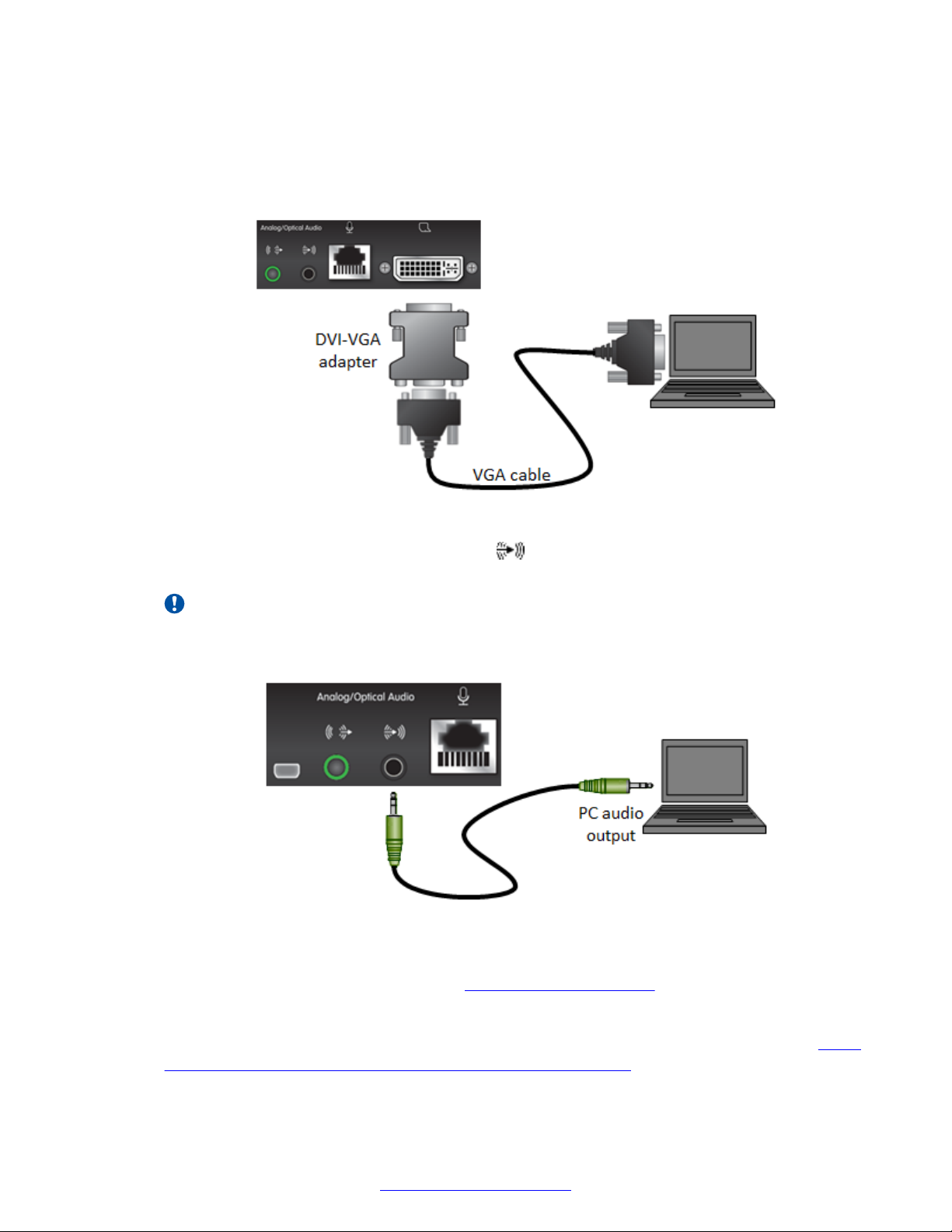
Setting Up the XT Series Hardware
Procedure
1. If your computer has a DVI port, connect it to the DVI port on the XT Codec Unit.
Alternatively, use the supplied DVI-VGA adapter to connect a VGA cable from the adapter to
the computer's VGA port.
Figure 42: Connecting a computer's display to the XT Series
2.
Connect the computer audio to the audio-in
port on the XT Codec Unit, which supports
both analog and digital optical audio.
Important:
Participants in the meeting can hear your computer’s audio even if you mute the audio
on the XT Series.
Figure 43: Connecting a computer's audio to the XT Series
When you connect a computer's audio output to the XT Series, the echo cancellation for this
analog input is disabled by default (see Configuring Microphones on page 104).
3. Set the computer's resolution by accessing the operating system graphics settings.
4. Select your screen resolution and refresh rates from the list of supported settings (see
10: Supported computer monitor resolutions and refresh rates on page 67).
66 Avaya Scopia
Table
®
XT Series Deployment Guide April 2015
Comments? [email protected]
Page 67
Connecting a Computer to the XT Series
Table 10: Supported computer monitor resolutions and refresh rates
Name Resolution Digital Refresh Rate
1080p 1920x1080 60 60
SXGA 1280x1024 60,75 60, 75
HD+ (900p) 1600x900 60 N/A
WSGA 1440x900 60 60
UVGA 1280x960 60, 85 60, 85
WXGA 1280x768 / 1280x800 60 60
720p 1280x720 60 60
XGA 1024x768 60, 70, 75 60, 70, 75
SVGA 800x600 60, 72, 75 60, 72, 75
VGA 640x480 72, 75 72, 75
5. To share content from your computer, continue with User Guide for Avaya Scopia® XT
Series.
Related Links
Setting Up the XT Series Hardware on page 42
(Hz)
Analog Refresh Rate
Frequency (Hz)
April 2015 Avaya Scopia® XT Series Deployment Guide 67
Comments? [email protected]
Page 68

Chapter 5: Controlling the XT Series
There are a number of ways to interact with the Avaya Scopia® XT Series:
• Use the XT Remote Control Unit locally on the endpoint itself to navigate the menus and
perform user functions and advanced configuration. You view the results on a connected
monitor.
• (Scopia® XT Executive only) Use a keyboard and mouse of a computer connected to the
endpoint to navigate its menus instead of the XT Remote Control Unit. This also requires a
connected monitor.
• Use the Scopia® Control iPad app to control user-level functionality of the XT Series via an
intuitive touch interface. This app is limited to user features, and does not extend to
administration or advanced configuration. For more information, see User Guide for Scopia
Control.
• Use the XT Series's web interface to perform nearly all features from the unit's web page.
• Use Scopia® Management's administrator web interface to perform system upgrades, backups,
and add your endpoint to the organization's address book (see
Series from Scopia® Management on page 76).
Managing Avaya Scopia® XT
®
Related Links
Accessing the XT Series Local Menu on page 68
About the XT Remote Control Unit on page 70
Navigating Menus with the Keyboard and Mouse on page 73
Accessing XT Series Web Interface on page 75
Managing Avaya Scopia® XT Series from Scopia® Management on page 76
Accessing the XT Series Local Menu
About this task
After switching on the XT Series, the main menu appears on the connected monitor.
To navigate the local menus, use the XT Remote Control Unit or for Scopia® XT Executive only, you
can use a keyboard and mouse. You can also access the system via the web, where the main
screen is laid out differently (see
Accessing XT Series Web Interface on page 75).
68 Avaya Scopia
®
XT Series Deployment Guide April 2015
Comments? [email protected]
Page 69
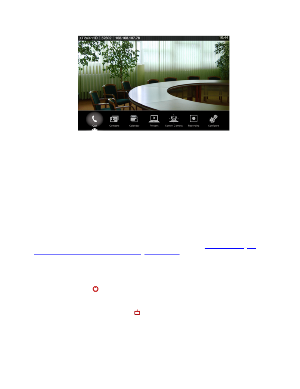
Figure 44: XT Series main menu
The main menu offers the following features:
• Call starts audio and video calls.
Accessing the XT Series Local Menu
• Contacts allows you to view, edit, and call a contact.
• Calendar allows you to view and join meetings scheduled for this endpoint.
• Present starts sharing content from your computer, or displays the connected computer's
content.
• Control Camera adjusts camera position.
• Recording allows you to record and playback a videoconference (may require a license).
• Configure adjusts settings and checks the system status.
Before you begin
(Scopia® XT Executive only) To navigate menus with a keyboard and mouse, you must first connect
your computer and then complete the Quick Setup Wizard which ends with installing the Scopia® XT
Control utility to use the keyboard and mouse for menu navigation (see
Installing Scopia® XT
Control to Use Keyboard and Mouse (Scopia® XT Executive) on page 91).
Procedure
1. Check the light on the front of the XT Codec Unit. When it is connected to power but
switched off, the LED blinks.
2.
Press the power
switched on, the LED remains on (no blinking).
3. (Scopia® XT Executive only),Access the main menu by pressing ok/menu on the XT
Remote Control Unit, or select the Scopia® XT Control icon on your taskbar.
key on the XT Remote Control Unit to turn on the XT Codec Unit. When
4. The system home page appears on the monitors.
When you access the system for the first time only, the Quick Setup wizard is displayed (see
Configuring Basic Settings with the Quick Setup Wizard on page 83).
April 2015 Avaya Scopia® XT Series Deployment Guide 69
Comments? [email protected]
Page 70

Controlling the XT Series
5. Navigate using the XT Remote Control Unit or on the Scopia® XT Executive only, you can
also use the keyboard and mouse.
Related Links
Controlling the XT Series on page 68
About the XT Remote Control Unit
There are several ways to control the Avaya Scopia® XT Series. This section explains how to use
the XT Remote Control Unit to navigate the endpoint's menus which are displayed on the endpoint's
monitor. Without a monitor, you cannot interact using the XT Remote Control Unit.
Other ways to control and interact with the XT Series include:
• Using the web interface (see Accessing XT Series Web Interface on page 75).
• (Scopia® XT Executive only) Using your keyboard and mouse (see Navigating Menus with the
Keyboard and Mouse on page 73).
• Using Scopia® Control on an Apple iPad to control user functionality (see User Guide for
Scopia® Control).
The XT Remote Control Unit has an improved design for a more efficient videoconferencing
experience (Figure 45: The XT Remote Control Unit on page 71).
70 Avaya Scopia
®
XT Series Deployment Guide April 2015
Comments? [email protected]
Page 71
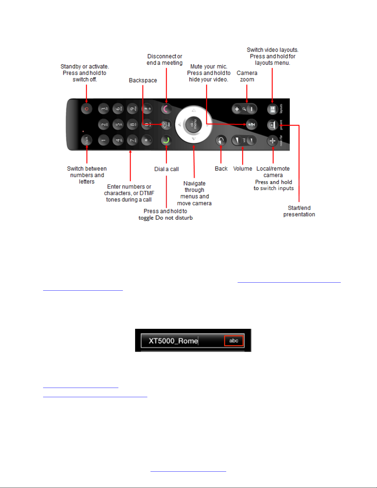
About the XT Remote Control Unit
Figure 45: The XT Remote Control Unit
Scroll through menus and options using the arrow keys and pressing the ok/menu key to select an
item.
Enter letters and digits into a field using the remote's keypad on the XT Remote Control Unit. The
system displays the current entry method to the right of the field (
Figure 46: Entry method displayed
to the right of an input field on page 71). You can switch entry methods by pressing the 1/a/A
button repeatedly while the cursor is in the input field, to switch between abc1 (default) for lower
case alphanumeric characters, ABC for upper case characters only (no digits), abc for just lower
case characters only (no digits), and 123 for digits only. To enter a letter or number, press a key
repeatedly to cycle through its characters.
Figure 46: Entry method displayed to the right of an input field
Related Links
Controlling the XT Series on page 68
Pairing an XT Remote Control Unit on page 72
April 2015 Avaya Scopia® XT Series Deployment Guide 71
Comments? [email protected]
Page 72
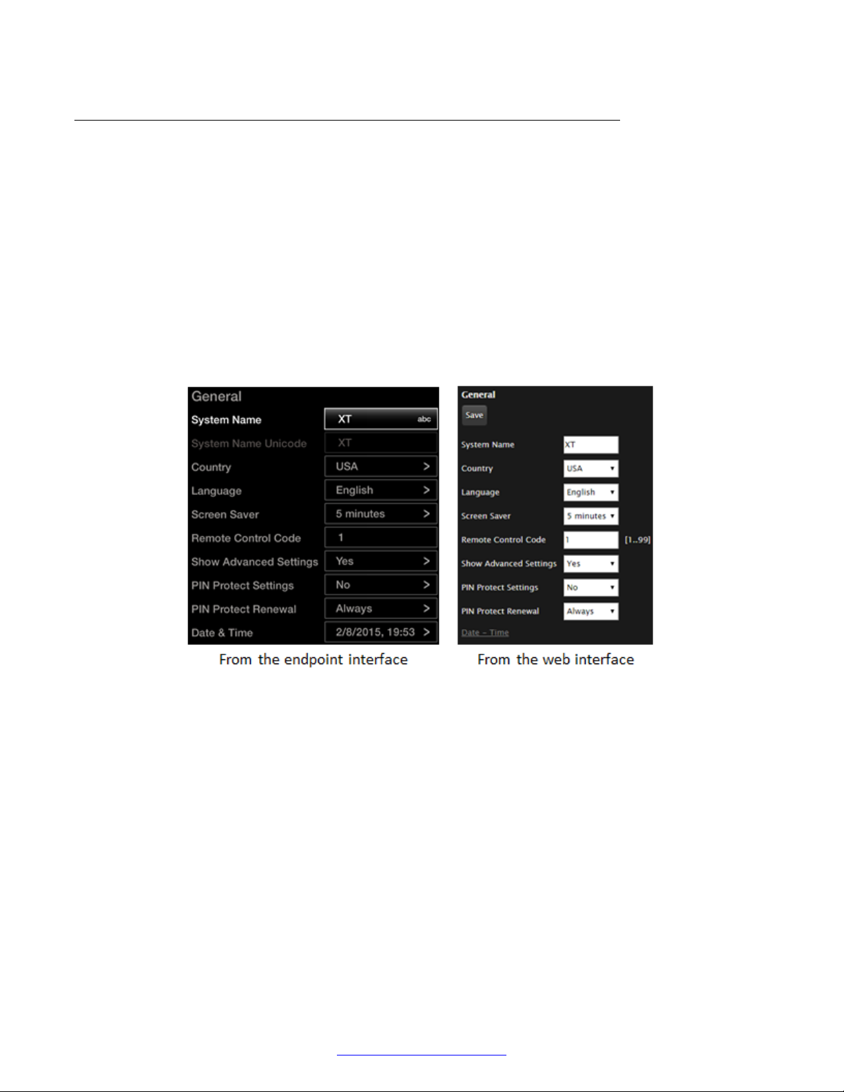
Controlling the XT Series
Pairing an XT Remote Control Unit
About this task
If you have multiple XT Series units in the same room, you can pair a XT Remote Control Unit with
its XT Codec Unit so that every unit has its dedicated remote, so when you press a key on a remote,
it triggers an action on the correct XT Series unit. Enter the same numeric code in both the XT
Series and its XT Remote Control Unit to pair them. By default all remotes and endpoints use the
same code 01.
Procedure
1. Access the general settings. From the XT Series web interface, select Basic Settings >
General. From the endpoint's main menu, select Configure > General.
You can use the XT Remote Control Unit's initial default pairing to perform this task.
2. Enter a two-digit numeric code between 01 and 99 in the Remote Control Code field.
3. From the web interface only, select Save.
4. On the XT Remote Control Unit, press the * and # keys simultaneously until its red light
blinks twice.
72 Avaya Scopia
Figure 47: Setting the XT Remote Control Unit Code
®
XT Series Deployment Guide April 2015
Comments? [email protected]
Page 73
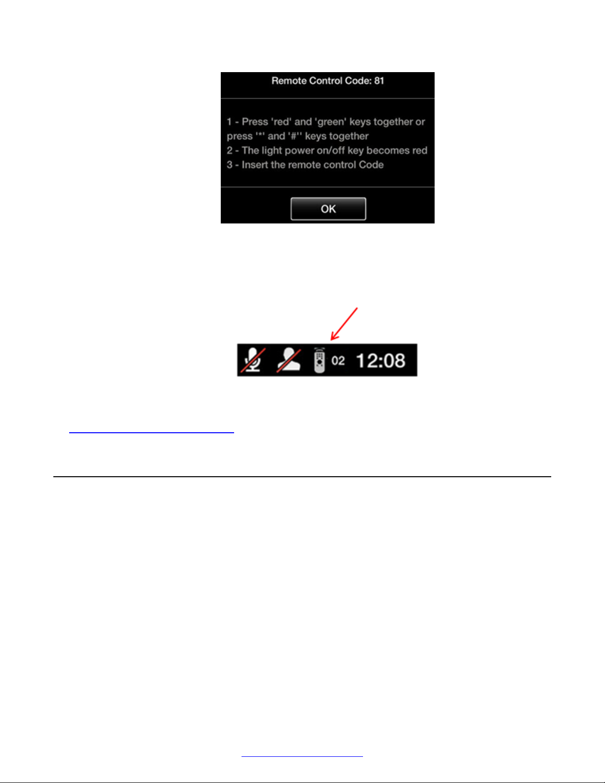
Navigating Menus with the Keyboard and Mouse
Figure 48: Setting the code on the XT Remote Control Unit
5. Using the keypad, type the same number used in the Remote control code field.
When the code is not the default 01, the system displays the paired remote icon with its new
code at the top-right corner of the screen.
6. Select Finish in the web interface, or select OK on the endpoint.
Related Links
About the XT Remote Control Unit on page 70
Navigating Menus with the Keyboard and Mouse
About this task
On the Scopia® XT Executive only, you can navigate through endpoint menus using your
computer's keyboard and mouse instead of the remote control, by running a PC or Mac program
called Scopia® XT Control. It also allows you to seamlessly switch between your computer screen
and the system menus. By default, your computer screen is always displayed when you are not in a
call.
April 2015 Avaya Scopia® XT Series Deployment Guide 73
Comments? [email protected]
Page 74
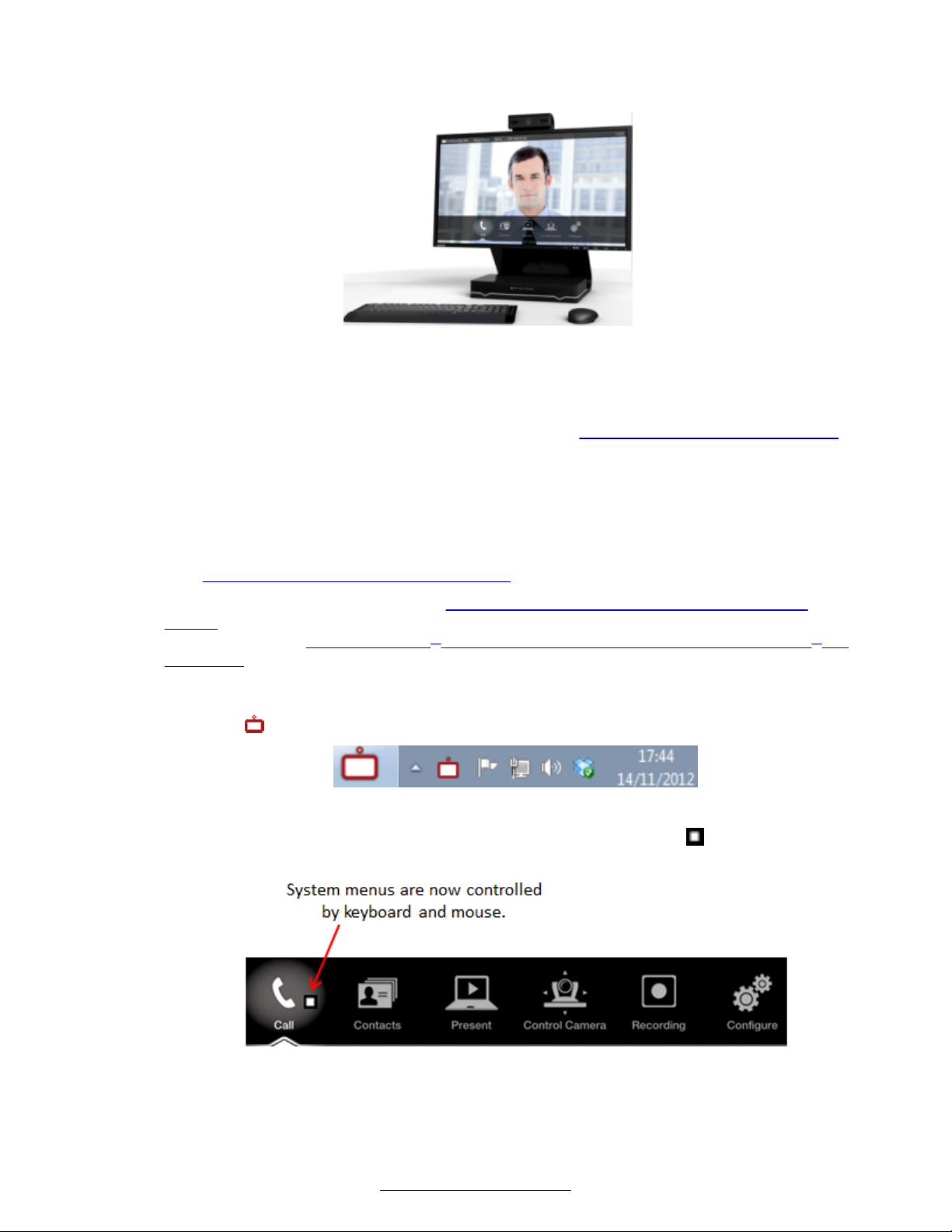
Controlling the XT Series
Figure 49: Controlling your Scopia® XT Executive with your computer
Scopia® XT Control also offers shortcuts for some commonly used tasks, such as sharing content
during a call.
You can still use the XT Remote Control Unit at any time (see About the XT Remote Control Unit on
page 70 for details).
Before you begin
To access the endpoint's main menu using your keyboard and mouse, you must first perform the
following procedures:
1. Connect your computer to the Scopia® XT Executive to use it as your computer's monitor
Connecting a Computer to the XT Series on page 65).
(see
2. Perform the initial setup described in
Configuring Basic Settings with the Quick Setup
Wizard on page 83. The last step of the quick setup wizard is installing the Scopia® XT
Control utility (see Installing Scopia® XT Control to Use Keyboard and Mouse (Scopia® XT
Executive) on page 91).
Procedure
1.
Select the Scopia® XT Control icon in your taskbar:
The icon turns gray indicating the keyboard and mouse control the endpoint navigation, the
menus appear on the screen, and the mouse cursor is now a square . Move the mouse all
the way to the edge of the screen to ensure the square icon follows its movements.
74 Avaya Scopia
®
XT Series Deployment Guide April 2015
Comments? [email protected]
Page 75
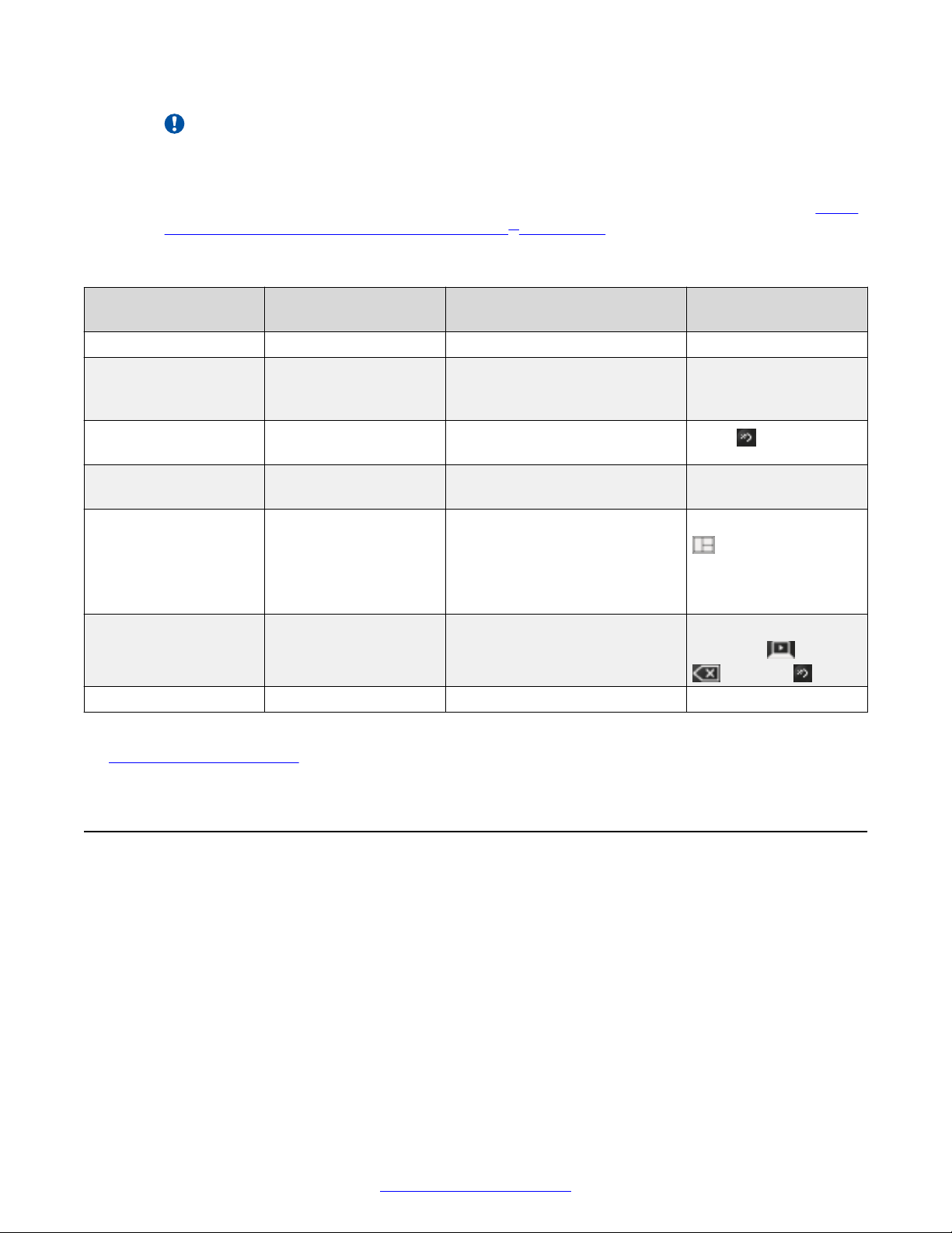
Accessing XT Series Web Interface
Important:
On the Scopia® XT Executive, the system menus are automatically activated when you
receive an incoming call to allow you accept or reject the call.
2. Scopia® XT Control enables a number of functions using the keyboard or mouse (see Table
11: Using the keyboard or mouse with Scopia® XT Control on page 75).
Table 11: Using the keyboard or mouse with Scopia® XT Control
Function Using your keyboard Using your mouse Using XT Remote
Control Unit
Select an option Press Enter. Click on the option. Press ok/menu.
Enter text Use the keyboard. N/A Use the XT Remote
Control Unit keypad to
enter letters and digits.
Go back to previous
page
Navigate endpoint
menus
Move windows in
video layout
Switch control to
computer
Zoom in or out - Scroll up or down Press the zoom keys.
Press Esc. Click on an empty area on the
screen.
Press the arrows then
Enter.
- Drag and drop the windows to
Press Esc, Backspace,
or Ctrl+Shift+1.
Select the option. Use the arrow keys then
the desired position.
Select the window in the layout
representing your desktop.
Press Back.
ok/menu.
Press and hold Layouts
and select the
desired layout (see
User Guide for Avaya
Scopia® XT Series).
When you are not in a
call, press Present,
Delete or Back.
Related Links
Controlling the XT Series on page 68
Accessing XT Series Web Interface
About this task
This procedure describes how to access the Avaya Scopia® XT Series web interface, which
supports the following internet browsers:
• Internet Explorer version 8 or later
• Google Chrome version 11 or later
• Mozilla Firefox version 3.6 or later
• Apple Safari version 5 or later
• Opera version 11 or later
April 2015 Avaya Scopia® XT Series Deployment Guide 75
Comments? [email protected]
Page 76
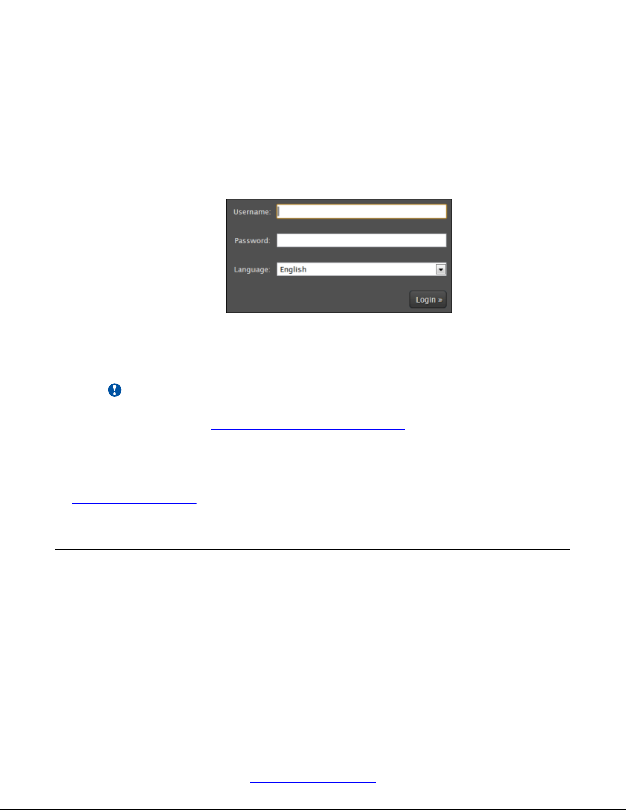
Controlling the XT Series
If you have a monitor, you can find the IP address at the top bar of the endpoint's monitor.
Before you begin
Web access is enabled by default. If it was disabled, you can enable it and configure the security
details as described in
Securing Web Access to the XT Series on page 157.
Procedure
1. Open any of the supported internet browsers and access the XT Series login page by
entering the system's IP address, like http://1.2.3.4/.
Figure 50: Logging into the XT Series web interface
2. Enter the username and password.
The default username for the web interface is Admin with the password 1234.
Important:
We recommend changing the default credentials after logging in for the first time, as
described in the
3. (Optional) Select the web interface language from the Language list.
4. Select Login.
Related Links
Controlling the XT Series on page 68
Managing Avaya Scopia® XT Series from Scopia
Securing Web Access to the XT Series on page 157.
®
Management
About this task
Scopia® Management can manage all endpoints in a video network, including the Avaya Scopia
XT Series. Remote management is used for:
®
• Viewing Scopia® Management meeting schedules which include this endpoint as a participant.
• Recording meetings to your organization's Scopia® Desktop Content Center server.
• Centralizing upgrades and remote backups of the configuration settings of XT Series.
76 Avaya Scopia
®
XT Series Deployment Guide April 2015
Comments? [email protected]
Page 77
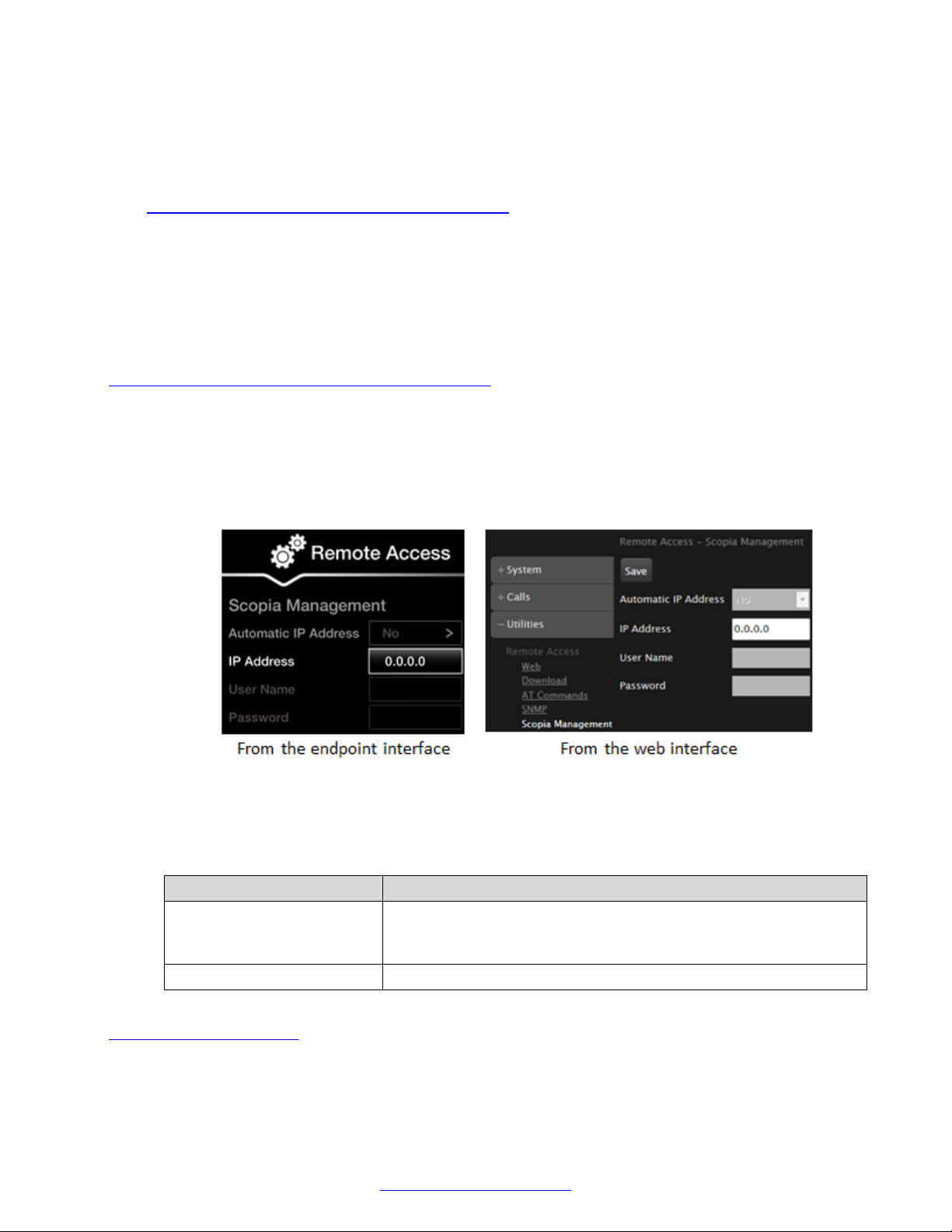
Managing Avaya Scopia® XT Series from Scopia® Management
• Synchronizing contacts for all endpoints in a network from the corporate directory, including XT
Series.
• Synchronizing settings of all XT Series devices in your organization. You can export the
settings of one unit into a configuration file, then import those settings to other units (see
Enabling System Logs and Remote Initialization on page 175).
You must enable AT and SNMP functionality to work with Scopia® Management.
For more information on adding, removing and upgrading the system remotely in Scopia
®
Management, or for details on synchronizing contacts for the endpoints in your organization, see
Administrator Guide for Avaya Scopia® Management.
Before you begin
If configuring from the endpoint, you must first enable advanced configuration, as described in
Enabling Advanced Maintenance on the XT Series on page 112.
Procedure
1. Access the Scopia® Management remote access settings. From the XT Series web
interface, select Administrator Settings > Utilities > Remote Access > Scopia
Management. From the endpoint's main menu, select Configure > Advanced > Utilities >
Remote Access > Scopia® Management.
®
Figure 51: Granting Scopia® Management remote management of the XT Series
2. Set the fields as required.
Table 12: Granting remote access to Scopia® Management
Field Name Description
Automatic IP Address Not currently supported. Select Yes for the system to automatically
know the Scopia® Management, sent by Scopia® Management
when controlling the device.
IP Address Enter the IP address of the Scopia® Management server.
Related Links
Controlling the XT Series on page 68
April 2015 Avaya Scopia® XT Series Deployment Guide 77
Comments? [email protected]
Page 78

Chapter 6: Initial Configuration of the XT
Series
After connecting the system hardware and powering it on as described in
Hardware on page 42, perform the initial configuration as described in these sections:
Related Links
Activating the XT Series and its Optional Features on page 78
Configuring Basic Settings with the Quick Setup Wizard on page 83
Configuring Monitors on page 96
Configuring Cameras on page 100
Configuring Microphones on page 104
Registering the XT Series to a SIP Server on page 107
Setting Up the XT Series
Activating the XT Series and its Optional Features
About this task
You need license keys to activate the Avaya Scopia® XT Series for the first time, and to enable
certain features (like increased bandwidth or resolution). The available licenses depend on the
model of your XT Series, as described in
You first generate the license keys in the Avaya Product Licensing and Delivery System (see
Getting Started with Avaya PLDS). Once you have the license keys, you activate the XT Series and
any optional features you purchased, as described below the table. You can do this from the
endpoint itself or from its web interface.
XT Series software options on page 79.
Important:
Without a license key to activate the product, you can only use the system in preview mode for
30 days.
78 Avaya Scopia
®
XT Series Deployment Guide April 2015
Comments? [email protected]
Page 79
Table 13: XT Series software options
Activating the XT Series and its Optional Features
Feature License number
and name
Bandwidth and
Network
55111-00904
Avaya Scopia® XT
Series 12Mbps
Option
Audio 55111-00948
Additional Audio
Codec Pack
Network 55111-00916
Avaya Scopia® XT
Series 2nd GLAN
Port
Available for Description
XT7000 Series
XT5000 Series
Scopia® XT
Executive
XT4000 Series
Increases total bandwidth to provide the best
videoconferencing experience by sending
video at a higher rate. This is especially useful
when hosting meetings on your endpoint, to
send video at a higher rate than the default
6Mbps total for all participants.
On the XT7000 Series, XT5000 Series,
XT4300 and Scopia® XT Executive, this option
increases the bandwidth to:
• 12Mbps for locally-hosted meetings
• 10Mbps for SIP point-to-point calls
• 8128kbps for H.323 calls
On the XT4200, it increases point-to-point calls
to 6Mbps.
XT7000 Series
XT5000 Series
Scopia® XT
Executive
XT4000 Series
XT5000 720
XT4000 Series
Enhances the XT Series’s audio quality
without requiring a higher bandwidth by adding
the G.728 and G.729A audio codecs. These
codecs offer high quality audio with minimal
delay even during poor network conditions,
and increase interoperability with other devices
that support these codecs.
Enables a second 10/100/1000 network port
(one is enabled by default). This allows you to
separate network traffic. Large organizations,
for example, may want to route video on a
higher performance network, while routing the
API control of the XT Series on another
network. Smaller organizations may want to
use the XT Series as a firewall traversal
system, where the XT Series hosts a call on its
built-in MCU, and endpoints from both the
public and private networks can access the
same videoconference.
This option is already enabled on XT7000
Series, Scopia® XT Executive and other
XT5000 Series models (excluding the XT5000
720).
Avaya Scopia® XT
Series MCU Edition
Options
55111-00951 Full
MCU4 License
XT7000 Series
XT5000 Series
Enables hosting videoconferences with up to
four endpoints and controlling the XT Series
using the Scopia® Control app on the Apple
®
Table continues…
April 2015 Avaya Scopia® XT Series Deployment Guide 79
Comments? [email protected]
Page 80
Initial Configuration of the XT Series
Feature License number
and name
55111-00952 Full
MCU9 License
Avaya Scopia® XT
Series SMB Edition
55111-00941 Full
SMB4 License
Options
Available for Description
Scopia® XT
Executive
XT4300
iPad®, which acts as a touchscreen remote
control.
For the XT5000 720 and XT4300, this option
also activates an extra network port, allowing
you to separate network traffic.
On some XT Series models, the extra port is
already enabled and does not require a license
(see the 55111-00916 Avaya Scopia® XT
Series 2nd GLAN Port license, above).
XT7000 Series
XT5000 Series
XT4300
Enables hosting videoconferences with up to
nine endpoints and controlling the XT Series
using the Scopia® Control app on the Apple
iPad®, which acts as a touchscreen remote
control.
For the XT5000 720 and XT4300, this option
also activates an extra network port, allowing
you to separate network traffic.
On some XT Series models, the extra port is
already enabled and does not require a license
(see the 55111-00916 Avaya Scopia® XT
Series 2nd GLAN Port license, above).
XT7000 Series
XT5000 Series
Scopia® XT
Executive
XT4300
Enables hosting videoconferences with up to
four participants joining from an endpoint, a
computer, web browser, or a mobile device.
For the XT5000 720, Scopia® XT Executive,
and XT4300, this option also enables you to
control the XT Series using the Scopia
Control app on the Apple® iPad®, which acts
as a touchscreen remote control.
®
®
80 Avaya Scopia
For the XT5000 720 and XT4300, this option
also activates an extra network port, allowing
you to separate network traffic.
On some XT Series models, the extra port is
already enabled and does not require a license
(see the 55111-00916 Avaya Scopia® XT
Series 2nd GLAN Port license, above).
55111-00942 Full
SMB9 License
XT7000 Series
XT5000 Series
Enables hosting videoconferences with up to
nine participants joining from an endpoint, a
PC, web browser, or a mobile device. You can
control the XT Series using the Scopia
®
Control app on the Apple® iPad®, which acts
as a touchscreen remote control.
Table continues…
®
XT Series Deployment Guide April 2015
Comments? [email protected]
Page 81
Activating the XT Series and its Optional Features
Feature License number
and name
Video Resolution 55111-00937 Full
HD (1080p)
Zoom 55111-10922
Avaya Scopia® XT
Series Zoom
Upgrade
Scopia® Control 55111-00917
Scopia® Control
Recording
Videoconferences
55111-00933 USB
Recording License
A second monitor 55211-00914
Second HD display
enable
Available for Description
For the XT5000 720, this option also activates
an extra network port, allowing you to separate
network traffic.
On some XT Series models, the extra port is
already enabled and does not require a license
(see the 55111-00916 Avaya Scopia® XT
Series 2nd GLAN Port license, above).
XT5000 720 Boosts video resolution to 1080p instead the
default 720p.
This option is already enabled for the XT7000
Series, Scopia® XT Executive, XT4300, and
XT5000 Series models (excluding the XT5000
720).
XT5000 720
XT4000 Series
For the XT5000 720 and XT4200, increases
your PTZ camera to 40x total zoom (10x
optical and 4x digital).
For the XT4300, enables the digital zoom and
increases the total zoom to 15x (5x optical and
3x digital).
This option is already enabled for XT7000
Series and XT5000 Series models (excluding
the XT5000 720).
XT5000 720
Scopia® XT
Executive
XT4000 Series
Enables you to control the XT Series using the
Scopia® Control app on the Apple® iPad®,
which acts as a touchscreen remote control.
This option is already enabled for XT7000
Series and XT5000 Series models (excluding
the XT5000 720).
XT5000 720
Scopia® XT
Executive
XT4000 Series
You can record meetings to a locally
connected USB storage device or the network.
This option is already enabled for XT7000
Series and XT5000 Series models (excluding
the XT5000 720).
XT4300 You can add another monitor to enhance your
videoconferencing experience. This is useful,
for example, to see the presentation in fullscreen on one monitor, while viewing
participants on a second monitor.
This option is already enabled for all XT Series
models, excluding the XT4300.
April 2015 Avaya Scopia® XT Series Deployment Guide 81
Comments? [email protected]
Page 82

Initial Configuration of the XT Series
Before you begin
Verify that you have the following:
• Access to the
Avaya Product Licensing and Delivery System.
If you do not have access, navigate to Avaya's login page and follow the instructions on the
page. If you do not have login information for Avaya's login page, contact your Avaya Support
Representative.
• The endpoint’s host ID (MAC address of the GLAN 1 port), located in your customer letter. You
can also find this information from one of the endpoint’s interfaces. For example, when you
start the Avaya Scopia® XT Series without a license, you can click Activate License on the
Enable Software Version screen to view the host ID. Alternatively, you can click Start Demo
Version to run the software without a license for 30 days. On the demo version, you can
navigate to Configure > About. For more information on this method, see
Viewing System
Information for Customer Support on page 172. The host ID is also displayed on the XT Series
web interface when you log on to http://<XT Series IP address> with the username
Admin and the password 1234. When you log on, click Licenses. You can also use the
Licenses page to enable your license once you receive it from PLDS.
• A License Activation Code (LAC) to activate the product itself and any optional features you
purchased. You can find the LAC in the customer letter shipped with the product, or the email
you received when you purchased the product or optional license.
Procedure
1. Obtain the product’s license keys from the Avaya Product Licensing and Delivery System, as
follows:
a. Access the
Avaya Product Licensing and Delivery System.
b. Using your license activation code (LAC) and your endpoint’s host ID, obtain the license
key as described in Getting Started with Avaya PLDS.
The LAC generates a license key to activate the product, as well as any optional
licenses you ordered when purchasing the product. If you purchased optional licenses
separately, perform this step for each license you purchased, using its unique LAC.
Note:
If the LAC is not recognized by the Avaya Product Licensing and Delivery System,
use the following alternative method:
From the Avaya Product Licensing and Delivery System Home page, navigate to
Asset > View Entitlements > Search Entitlements. Search for your LAC by
entering it in the %LAC field. From the Options menu, click Activate. During the
Activation Wizard, you must manually create a new MAC address (Host ID).
c. Write down the license keys, required to activate the endpoint and its optional features.
2. Activate the license and/or optional features on your XT Series:
a. From the XT Series web interface, select Enable License on the home page. From the
endpoint's main menu, select Configure > Advanced > Utilities > Licenses.
82 Avaya Scopia
®
XT Series Deployment Guide April 2015
Comments? [email protected]
Page 83
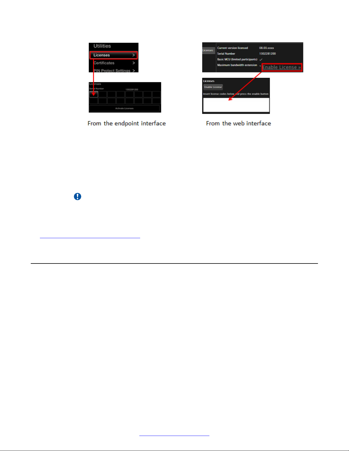
Configuring Basic Settings with the Quick Setup Wizard
Figure 52: Activating licenses
b. Enter the license keys you received from the PLDS, to either activate the product or
activate the optional features you purchased.
c. Select Enable License on the web interface, or Activate Licenses on the endpoint
itself.
The system automatically enables the license.
Important:
If you are enabling a second network port or Scopia® Control with a license, the XT
Codec Unit restarts.
Related Links
Initial Configuration of the XT Series on page 78
Configuring Basic Settings with the Quick Setup Wizard
About this task
To start using your Avaya Scopia® XT Series, first define basic settings with the quick setup wizard,
such as the system's name, language, and network settings. This is relevant for both new
installations, or after restoring default settings. You can only calibrate the image on the endpoint
itself using its monitor, not from the web interface.
Some settings may already be customized for your organization. If required, ask the system
administrator for the device's password.
The quick setup wizard automatically appears the first time you access the XT Series, either by
turning it on or logging in to the web interface. Alternatively select Configure > Quick Setup from
the Main Menu.
April 2015 Avaya Scopia® XT Series Deployment Guide 83
Comments? [email protected]
Page 84
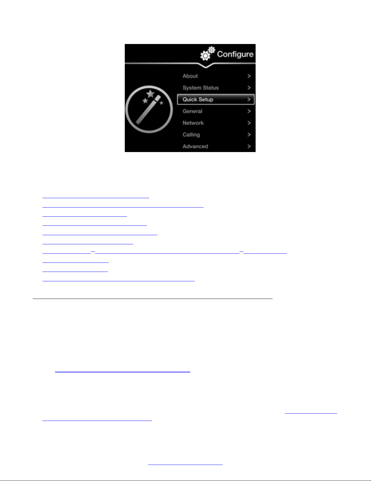
Initial Configuration of the XT Series
Figure 53: Accessing the Quick Setup
The quick setup wizard guides you through many of the following basic configuration tasks:
Related Links
Initial Configuration of the XT Series on page 78
Setting the System Name, Language, and Call Method on page 84
Adjusting the Image Position on page 86
Configuring Basic Network Settings on page 87
Configuring Basic Gatekeeper Settings on page 89
Configuring Basic SIP Settings on page 90
Installing Scopia® XT Control to Use Keyboard and Mouse (Scopia® XT Executive) on page 91
Setting Date and Time on page 93
Setting the Time Zone on page 94
Configuring the Screen Saver to Start Automatically on page 95
Setting the System Name, Language, and Call Method
About this task
The first screen in the Quick Setup wizard enables you to define the name of your Avaya Scopia
XT Series, the country, the menu language, and the protocol the system uses for calls. The unit's
name is displayed on the system's title bar and to other meeting participants. For example, Hong-
Kong, 9th-Floor-Room, or NY-Office. There is also a unicode system name to enable non-English
characters, available on the web interface only. For more advanced settings of the system name,
Configuring Advanced System Name Settings on page 114.
see
After initial setup, you can modify these settings by selecting Configure > General from the
endpoint's menus, or from the web interface select Basic Settings > Preferences > General.
Before you begin
Access the quick setup wizard from the endpoint or web interface, as described in
Settings with the Quick Setup Wizard on page 83.
84 Avaya Scopia
®
XT Series Deployment Guide April 2015
Comments? [email protected]
Configuring Basic
®
Page 85
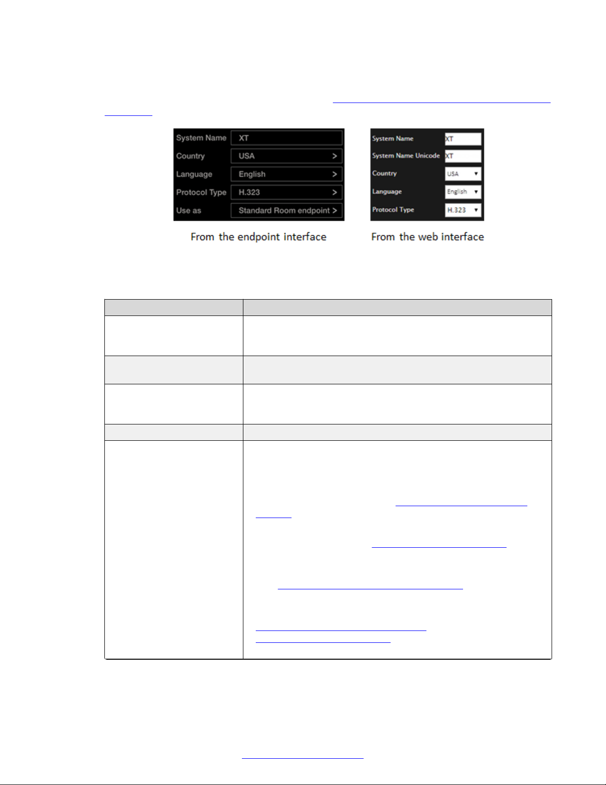
Configuring Basic Settings with the Quick Setup Wizard
Procedure
1. Define the name and language as described in Table 14: Defining name and language of the
XT Series on page 85.
Figure 54: Setting Country and Language
Table 14: Defining name and language of the XT Series
Field Description
System Name Enter the name of the XT Series in the System Name field. This
name is also used by default for the SIP username and the H.323
name, which can be manually changed.
System Name Unicode (Web interface only) Enter the name here if it includes non-ANSII
characters such as Chinese or Japanese.
Country Enter the country location of the unit. The system menu and the
Language field automatically changes to the language used in the
selected country.
Language Choose the language of the system menus.
Protocol Type Select the protocol the endpoint should use for calls, depending on
the organization’s existing infrastructure (SIP or H.323–based).
Contact your administrator for more information.
• H.323: Select if you are registering the endpoint to a gatekeeper
only. For more information, see Configuring Basic Gatekeeper
Settings on page 89 or contact your administrator.
• SIP: Select if you are registering the endpoint to a SIP server only.
For more information, see Configuring Basic SIP Settings on
page 90 or contact your administrator.
You can register the endpoint to as many as three SIP servers
(see Registering the XT Series to a SIP Server on page 107).
• H.323 and SIP: Select if you are registering the endpoint to both a
gatekeeper and a SIP server. For more information, see
Configuring Basic Gatekeeper Settings on page 89 and
Configuring Basic SIP Settings on page 90, or contact your
administrator.
Table continues…
April 2015 Avaya Scopia® XT Series Deployment Guide 85
Comments? [email protected]
Page 86

Initial Configuration of the XT Series
Field Description
Use as (Scopia® XT Executive only) Select whether this endpoint is used
2. To adjust the image on your monitor, select Next and continue with Adjusting the Image
Position on page 86.
with different computers:
• Select Personal Executive endpoint for a single user, where you
pair the computer once to the XT Series using Scopia® XT
Control.
• Select Shared Executive endpoint for multiple users, where you
pair the computer afresh with Scopia® XT Control each time you
connect.
• Select Standard Room endpoint for multiple users, if you do not
want to control the endpoint using a keyboard and mouse via
Scopia® XT Control. The endpoint is automatically set up with the
default settings of other XT Series models, rather than the
Scopia® XT Executive. For example, the monitor displays the
system menus when you are not in a call (as opposed to the
computer content, which is the default for Scopia® XT Executive).
If performing the quick setup from the web interface, access the quick setup from the
endpoint to adjust the image. This can be done at any time.
Related Links
Configuring Basic Settings with the Quick Setup Wizard on page 83
Adjusting the Image Position
About this task
You can center the endpoint's image correctly on its monitor in this stage of the Quick Setup Wizard.
This is for deployments with a monitor connected to your Avaya Scopia® XT Series.
Procedure
1. Access the Quick Setup Wizard from the endpoint, as described in Configuring Basic
Settings with the Quick Setup Wizard on page 83.
2. Decide if the monitor's image needs adjusting, by verifying if the white border of the triangles
in the top left and bottom right corners are fully visible on all sides.
If the image is centered correctly, skip this procedure and select Next.
86 Avaya Scopia
®
XT Series Deployment Guide April 2015
Comments? [email protected]
Page 87
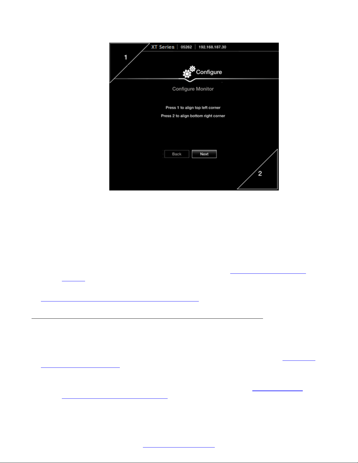
Configuring Basic Settings with the Quick Setup Wizard
Figure 55: Examining the image position
3. Press 1 to highlight the triangle in the top left corner in blue.
4. Use the arrow keys to position the image, so all sides of the white border of the triangle are
visible in the screen, then press ok/menu.
5. Press 2 to highlight the triangle in the bottom right corner in blue.
6. Adjust the image position in the same way, until all sides of the triangle border are visible,
then press ok/menu.
7. To continue with the Quick Setup Wizard, select Next (see
Settings on page 87).
Related Links
Configuring Basic Settings with the Quick Setup Wizard on page 83
Configuring Basic Network
Configuring Basic Network Settings
About this task
This procedure describes how to set up the basic network settings and the IP address of the XT
Series as part of the Quick Setup Wizard. To modify advanced network settings, see
Advanced Network Settings on page 116.
Configuring
Procedure
1. Access the Quick Setup Wizard from the endpoint, as described in Configuring Basic
Settings with the Quick Setup Wizard on page 83, and skip to this step.
April 2015 Avaya Scopia® XT Series Deployment Guide 87
Comments? [email protected]
Page 88
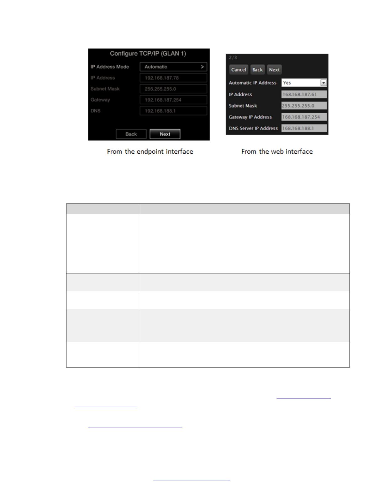
Initial Configuration of the XT Series
2. Enter the following values:
Table 15: Configuring the IP address
Figure 56: Defining IP Settings
Field Name Description
IP Address Mode or
Automatic IP Address
IP address Enter the system static IP address. For dynamic IP addresses, this field
Subnet mask Enter the subnet mask associated with the IP address. For dynamic IP
Gateway (IP Address) Enter the default gateway static IP address. The gateway is used to route
DNS (Server IP
Address)
Determines if the IP address is dynamically allocated (using DHCP), or if
you manually designate a static IP address. You must use only static
addresses for:
• Scopia® XT Telepresence deployments
• Units on a public network
• SIP deployments where the unit is secured with a TLS certificate.
displays the current IP address.
addresses, this field displays the current subnet mask.
information between two subnets, for example, between the headquarters
and a partner site. For dynamic IP addresses, this field displays the
current gateway IP address.
Enter the DNS server IP address. The DNS server translates domain
names into IP addresses. For dynamic IP addresses, this field displays
the assigned DNS server IP address.
3. Select Next and continue with one of the following, depending on whether you are
registering your endpoint to a gatekeeper or SIP server:
• If you are registering your endpoint to a gatekeeper, continue with Configuring Basic
Gatekeeper Settings on page 89.
• If you are only registering your endpoint to a SIP server (and not a gatekeeper), continue
with Configuring Basic SIP Settings on page 90.
88 Avaya Scopia
®
XT Series Deployment Guide April 2015
Comments? [email protected]
Page 89
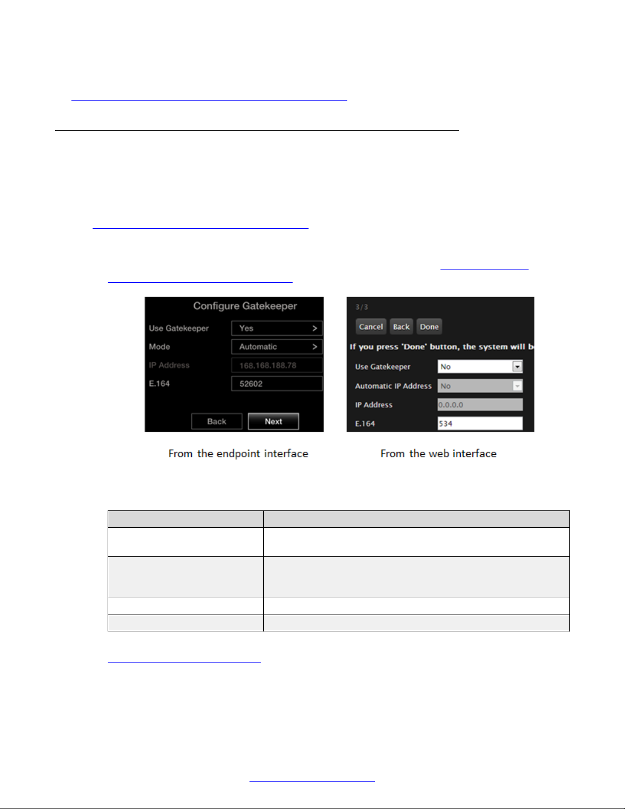
Configuring Basic Settings with the Quick Setup Wizard
Related Links
Configuring Basic Settings with the Quick Setup Wizard on page 83
Configuring Basic Gatekeeper Settings
About this task
Configure the gatekeeper settings if your Avaya Scopia® XT Series works with one. A gatekeeper
routes audio and video H.323 calls by resolving dial strings (H.323 alias or URI) into the IP address
of an endpoint, and handles the initial connection of calls. To modify advanced gatekeeper settings,
Configuring Advanced Gatekeeper Settings on page 124.
see
Procedure
1. Access the Quick Setup Wizard from the endpoint, as described in Configuring Basic
Settings with the Quick Setup Wizard on page 83, and skip to this step.
Figure 57: Gatekeeper settings
2. Configure the gatekeeper connection as described in the following table.
Field Description
Use Gatekeeper Choose whether this endpoint is registered to a gatekeeper, like
the Avaya Scopia® ECS Gatekeeper.
Mode or Automatic IP
Address
Gatekeeper IP address Enter the IP address of the gatekeeper.
E.164 Enter the H.323 number required to dial the XT Series.
Choose whether the gatekeeper is configured to automatically
detect endpoints. For more information, ask your network
administrator.
3. If you are registering your endpoint to a SIP server, select Next and continue with
Configuring Basic SIP Settings on page 90. Otherwise, select Done to complete the Quick
Setup Wizard.
April 2015 Avaya Scopia® XT Series Deployment Guide 89
Comments? [email protected]
Page 90
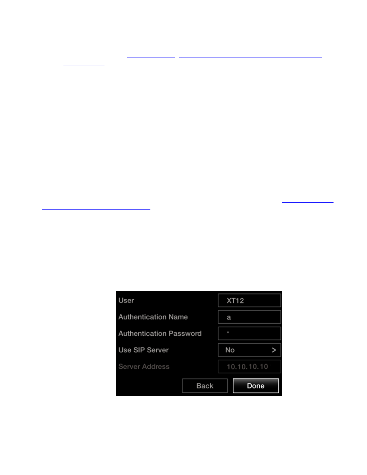
Initial Configuration of the XT Series
For Scopia® XT Executive only, to configure using your keyboard and mouse to navigate the
menus, continue with Installing Scopia® XT Control to Use Keyboard and Mouse (Scopia
XT Executive) on page 91.
Related Links
Configuring Basic Settings with the Quick Setup Wizard on page 83
Configuring Basic SIP Settings
About this task
This section explains how to register your XT Series to the SIP server.
The XT Series can function in a SIP environment, where aliases are managed by SIP servers, not
gatekeepers. You can dial an endpoint by entering its alias like 1234 or joe_smith, rather than
remembering its IP address, where the SIP server routes the call correctly. To do this, the SIP
server must register all endpoints to maintain the mapping list of aliases and endpoints to
successfully route calls.
Before you begin
®
Access the quick setup wizard from the endpoint or web interface, as described in
Configuring Basic
Settings with the Quick Setup Wizard on page 83, and skip to this step.
Verify that you have the following information about your SIP environment:
• The DNS name or IP address of the SIP server. You can define up to three servers.
• For the SIP infrastructure that requires a SIP user authentication, credentials for authenticating
XT Series to the SIP server.
Procedure
1. Enter information for the SIP server, as described below.
In redundant SIP deployments, the XT Series uses this server as the default SIP server.
90 Avaya Scopia
Figure 58: Configuring basic SIP settings
®
XT Series Deployment Guide April 2015
Comments? [email protected]
Page 91
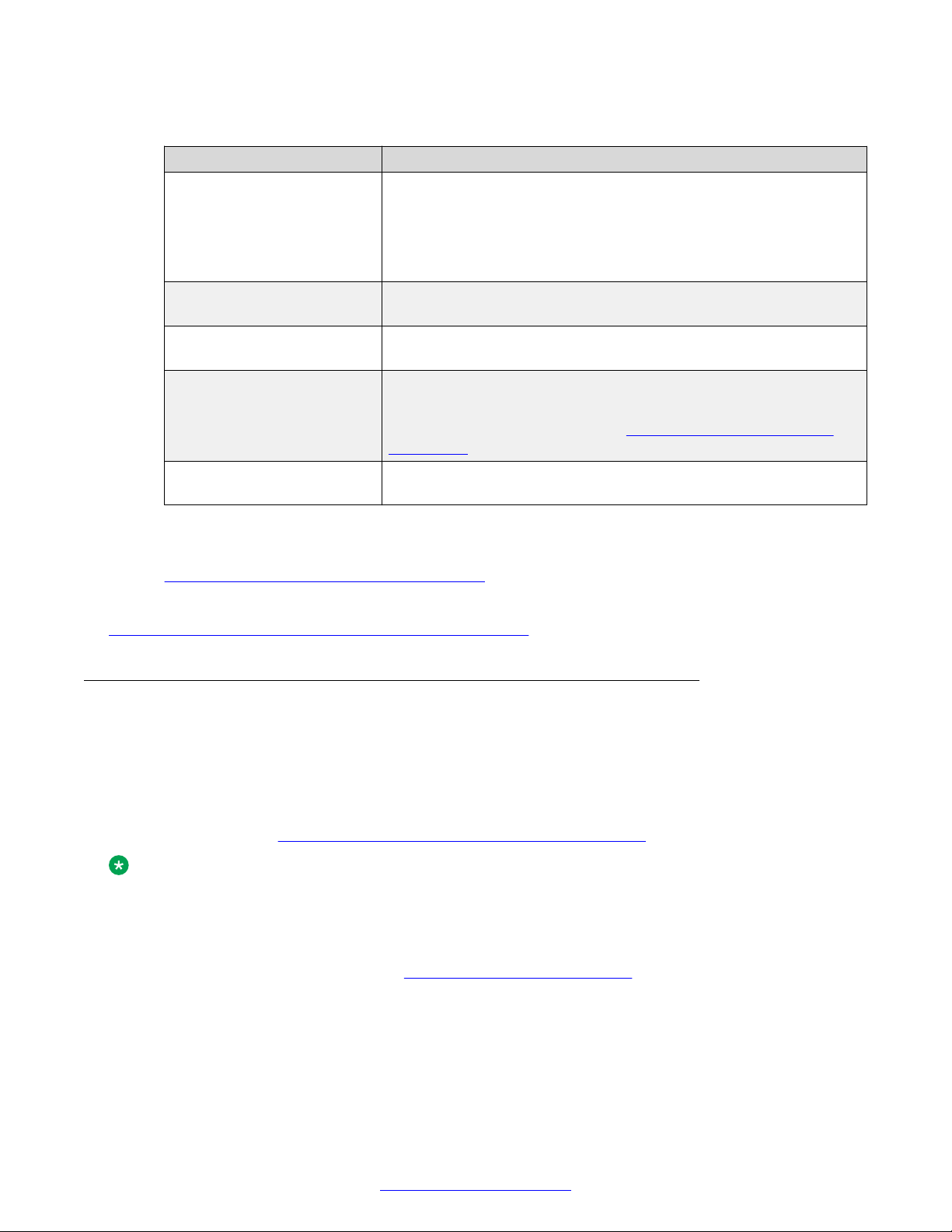
Configuring Basic Settings with the Quick Setup Wizard
Table 16: Configuring basic SIP settings for the XT Series
Field Description
User Enter the system name (alias). The system is registered to the SIP
server under this name.
When connecting over SIP, this name is displayed on the monitors
participating in the videoconference (for example, John-Smith, or
9th-Floor-Room) .
Authentication Name If necessary, enter the name for authenticating the XT Series with
the SIP server. It can be the same as the User parameter.
Authentication Password If necessary, enter the password for authenticating your XT Series
with the SIP server.
Use SIP Server Enable registering the system to the SIP server by selecting Yes.
For redundant SIP deployments, you can enter information for up to
three SIP servers, as described in Registering the XT Series to a
SIP Server on page 107.
Server Address Enter the DNS name or IP address of the SIP server, used to
register the endpoint.
2. Select Done to complete the Quick Setup Wizard.
3. To configure advanced SIP settings, such as the preferred transport protocol, see
Registering the XT Series to a SIP Server on page 107.
Related Links
Configuring Basic Settings with the Quick Setup Wizard on page 83
Installing Scopia® XT Control to Use Keyboard and Mouse (Scopia® XT Executive)
About this task
This procedure describes how to configure your Scopia® XT Executive (only) to navigate its menus
with a keyboard and mouse by installing Scopia® XT Control, a small standalone program for
Windows or Mac (see
Note:
You cannot install the Scopia® XT Control installation package on a Mac that is running the
Yosemite operating system. The Yosemite operating system does not allow you to install
packages obtained from outside of the Apple Store. However, there is a workaround available to
enable you to obtain and run the installation package if you have the Yosemite operating
system. For more information, see Resolving download problems on page 198.
Navigating Menus with the Keyboard and Mouse on page 73).
The Scopia® XT Control utility can only be installed from the endpoint's web interface.
April 2015 Avaya Scopia® XT Series Deployment Guide 91
Comments? [email protected]
Page 92
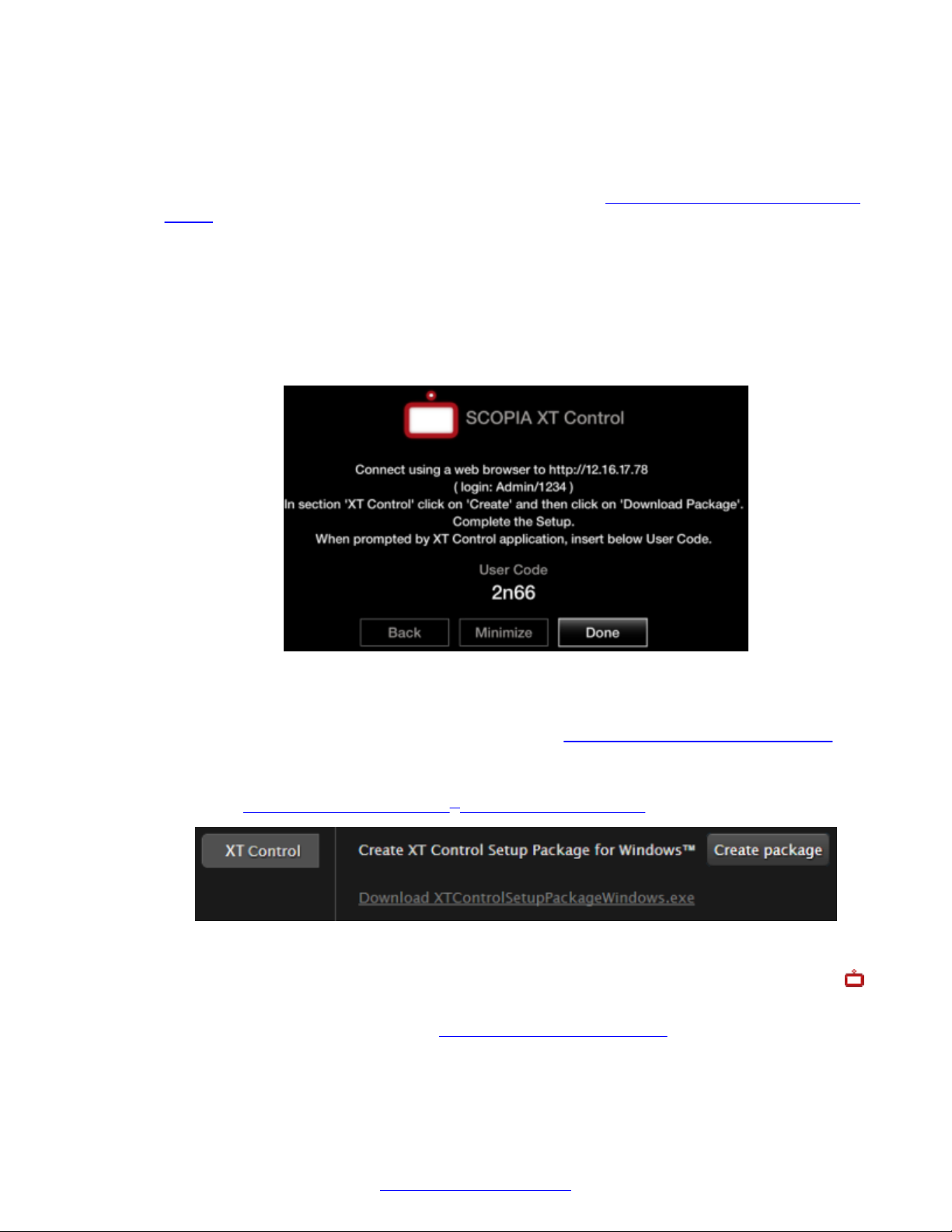
Initial Configuration of the XT Series
Before you begin
1. Verify your computer is running either Windows XP/Vista/7/8, or if it is a Mac, verify it is
running OSX 10.x, up to 10.9.
2. Connect your computer to the Scopia® XT Executive (see
Connecting a Computer to the XT
Series on page 65).
3. Perform the Quick Setup wizard, which ends with the Scopia® XT Control installation, or
install it at any time from the web interface.
Procedure
1. The Quick Setup wizard provides the web address to access your endpoint from the web,
and displays a user code to pair a computer's keyboard and mouse to the endpoint. You
enter this code at the end of the installation, so make a note of it now.
Figure 59: Installing Scopia® XT Control from the Quick Setup
2. Select Minimize to remove the window and expose your computer content.
3. Access the XT Series web interface, as described in Accessing XT Series Web Interface on
page 75.
4. In the main web page of the endpoint, in the Home > XT Control section, select Create
package (
5.
For Mac users only, copy the setup package to a folder on your computer, and launch the
Figure 60: Installing Scopia® XT Control for Windows on page 92).
Figure 60: Installing Scopia® XT Control for Windows
Scopia® XT Control:
You may need to follow the steps in Resolving download problems on page 198.
92 Avaya Scopia
®
XT Series Deployment Guide April 2015
Comments? [email protected]
Page 93
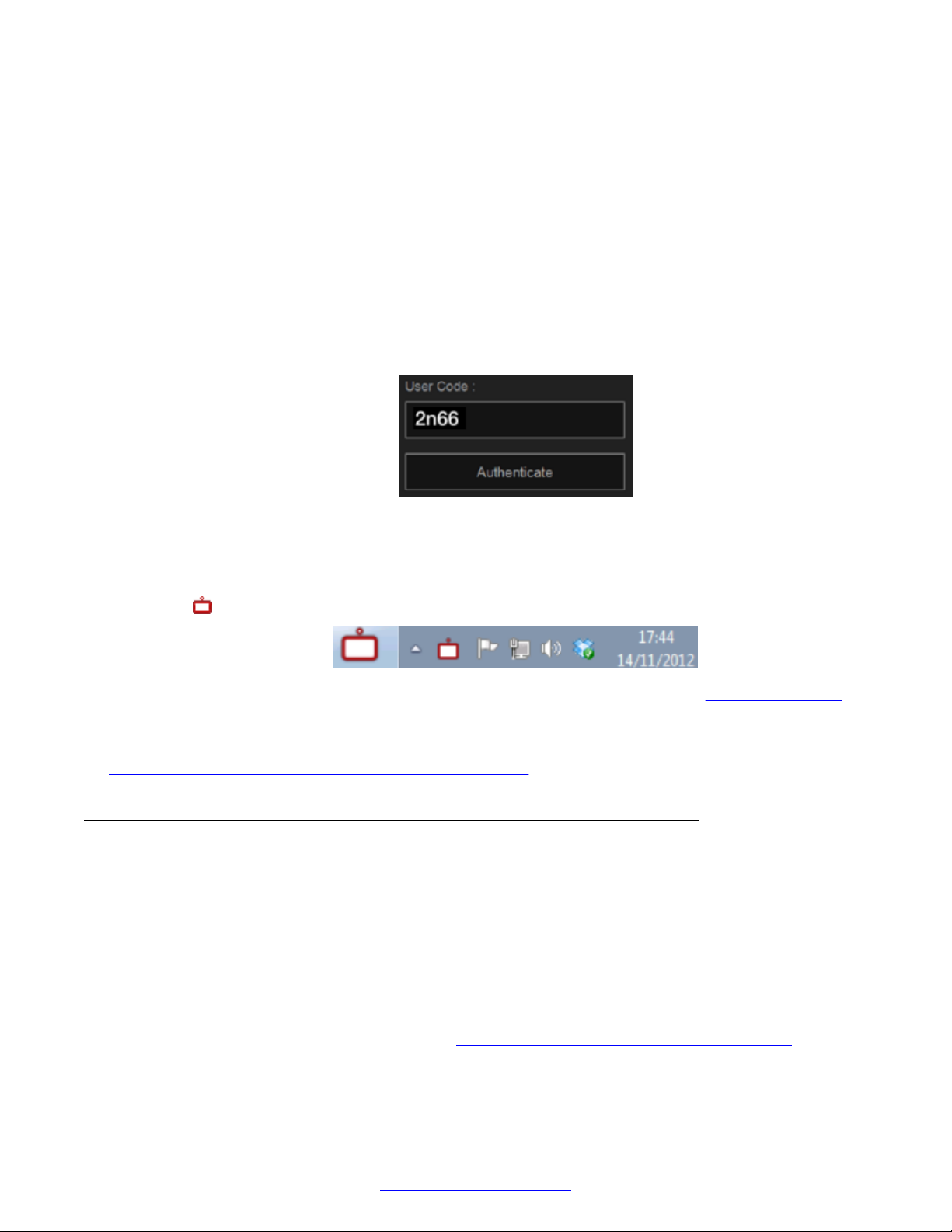
Configuring Basic Settings with the Quick Setup Wizard
6. For Windows users only, launch the installation package:
a. Select Next in the installation wizard and select to install Scopia® XT Control.
b. Select the installation folder and click Next.
c. Choose a location in the Start menu, and select Install.
d. Select Finish.
Scopia® XT Control automatically connects to the Scopia® XT Executive.
7. Use your keyboard to enter the user code displayed at the start of this procedure.
If you accidentally closed the code, leave the User Code field empty and select
Authenticate to display a new code.
Figure 61: Entering the user code (example)
8. Select Authenticate using your computer mouse.
9. You can now control the Scopia® XT Executive with your keyboard and mouse by selecting
the Scopia® XT Control icon in your taskbar:
For tips on getting started and using the Scopia® XT Control utility, see Navigating Menus
with the Keyboard and Mouse on page 73.
Related Links
Configuring Basic Settings with the Quick Setup Wizard on page 83
Setting Date and Time
About this task
You can set the date and time from either the endpoint or the web interface.
Procedure
1. Access the date and time settings. From the endpoint's main menu, select Configure >
General > Date & Time. From the XT Series web interface, select Basic Settings > Date Time.
2. Set the date and time, as described in Table 17: Configuring date and time settings on
page 94.
April 2015 Avaya Scopia® XT Series Deployment Guide 93
Comments? [email protected]
Page 94

Initial Configuration of the XT Series
If you set Internet time to Yes, you cannot modify the date and time fields.
Table 17: Configuring date and time settings
Field Name Description
Day, Month, Year,
Hour, Minutes
Internet time Select Yes to synchronize the system clock with the network clock, thus
Use Default NTP
Server, Server 1,
Server 2
Refresh time Enter the time period after which the system contacts the NTP server to
Enter the date and time.
allowing you to align devices connected to the Internet using Network
Time Protocol (NTP).
If your organization uses an external Network Time Protocol (NTP) server
for synchronizing the system clock, select Yes. If your organization uses
one or two internal NTP servers for that purpose, select No and enter the
server IP address in fields Server 1 and/or Server 2.
refresh the clock.
3. From the web interface only, select Save.
Related Links
Configuring Basic Settings with the Quick Setup Wizard on page 83
Setting the Time Zone
About this task
You can set the time zone from your endpoint or the XT Series web interface.
Before you begin
If configuring from the endpoint, you must first enable advanced configuration, as described in
Enabling Advanced Maintenance on the XT Series on page 112.
Procedure
1. Access the time zone settings. From the XT Series web interface, select Administrator
Settings > System > Date & Time > Time Zone. From the endpoint's main menu, select
Configure > Advanced > System > Date & Time > Time Zone.
You need to enter the PIN required to access the Advanced settings. The default PIN is
1234.
2. Configure settings as described in
page 95.
Table 18: Configuring time zone related settings on
94 Avaya Scopia
®
XT Series Deployment Guide April 2015
Comments? [email protected]
Page 95
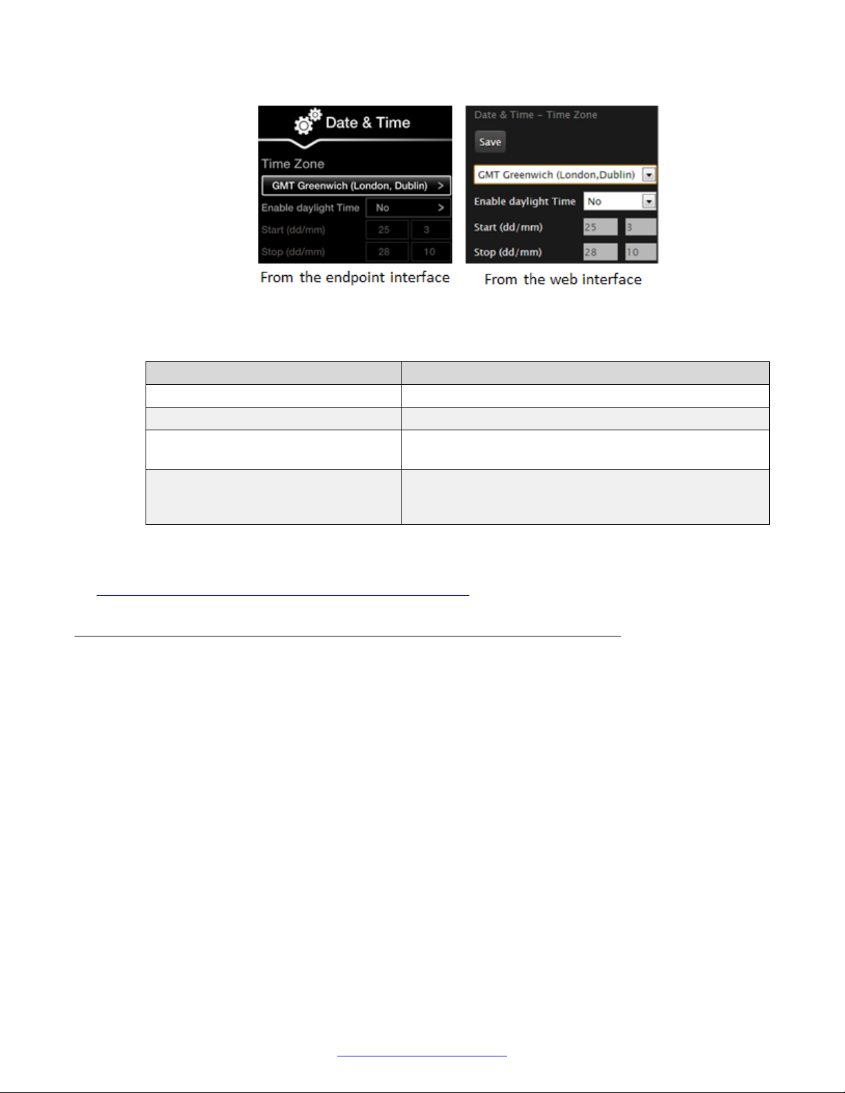
Configuring Basic Settings with the Quick Setup Wizard
Figure 62: Setting the time zone
Table 18: Configuring time zone related settings
Field Name Description
Time zone list Select the time zone to which the system belongs.
Enable daylight time Choose whether to enable daylight savings time.
Start (dd/mm) Set the day and month to indicate when daylight saving
time starts.
Stop (dd/mm) Set the day and month to indicate when daylight saving
time ends. If this is earlier than the start time, it assumes
the following year.
3. From the web interface only, select Save.
Related Links
Configuring Basic Settings with the Quick Setup Wizard on page 83
Configuring the Screen Saver to Start Automatically
About this task
The screen saver helps to protect the endpoint's monitor from burn-in without switching it off. For
Scopia® XT Executive with computers running the Scopia® XT Control utility, the screen saver does
not activate when using the computer while the endpoint is dormant. In this case, use the
computer's screen saver functionality.
Procedure
1. Access the screen saver settings. From the endpoint's main menu, select Configure >
General. From the XT Series web interface, select the Basic Settings tab.
April 2015 Avaya Scopia® XT Series Deployment Guide 95
Comments? [email protected]
Page 96
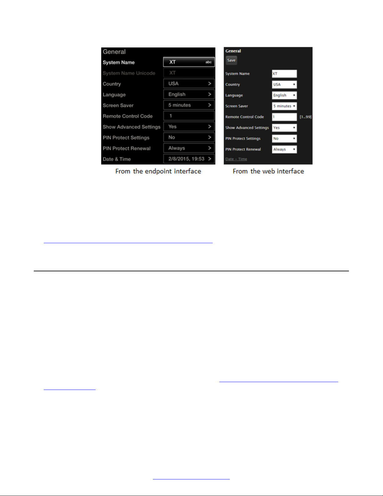
Initial Configuration of the XT Series
2. Set the time after which the screen saver automatically starts on the display in the Screen
Saver field.
Figure 63: Configuring screen saver settings
3. From the web interface only, select Save.
Related Links
Configuring Basic Settings with the Quick Setup Wizard on page 83
Configuring Monitors
About this task
After you connect one or two monitors to the HDMI ports on the Avaya Scopia® XT Series, you can
configure the number of monitors, their resolutions, and the allowed video layouts. However, the
Scopia® XT Executive only works with its own single monitor at a fixed resolution of 1080p.
For the XT4300, the additional monitor is available on a license.
Video layouts often require overlapping images when there are more video streams than available
monitors. For example, when your endpoint is disconnected, there is just local video stream which
fills the screen. If you call another endpoint with no presentation, there are two streams: the local
and the remote video. If you add a presentation, there are now three streams.
The available layouts depend on the number of monitors.
with presentation on page 97 shows the layouts for a single monitor. The PiP (Picture In Picture)
view shows a video image in the main screen, with an additional smaller image overlapping in the
corner. The PaP (Picture and Picture) view shows up to three images of the same size. The PoP
(Picture out Picture) view shows up to three images of different size, presented side by side, where
the image on the left is larger than the two smaller images on the right. For more information about
video layouts, see Avaya Scopia® XT Series User Guide.
Figure 64: Single monitor video layouts
96 Avaya Scopia
®
XT Series Deployment Guide April 2015
Comments? [email protected]
Page 97
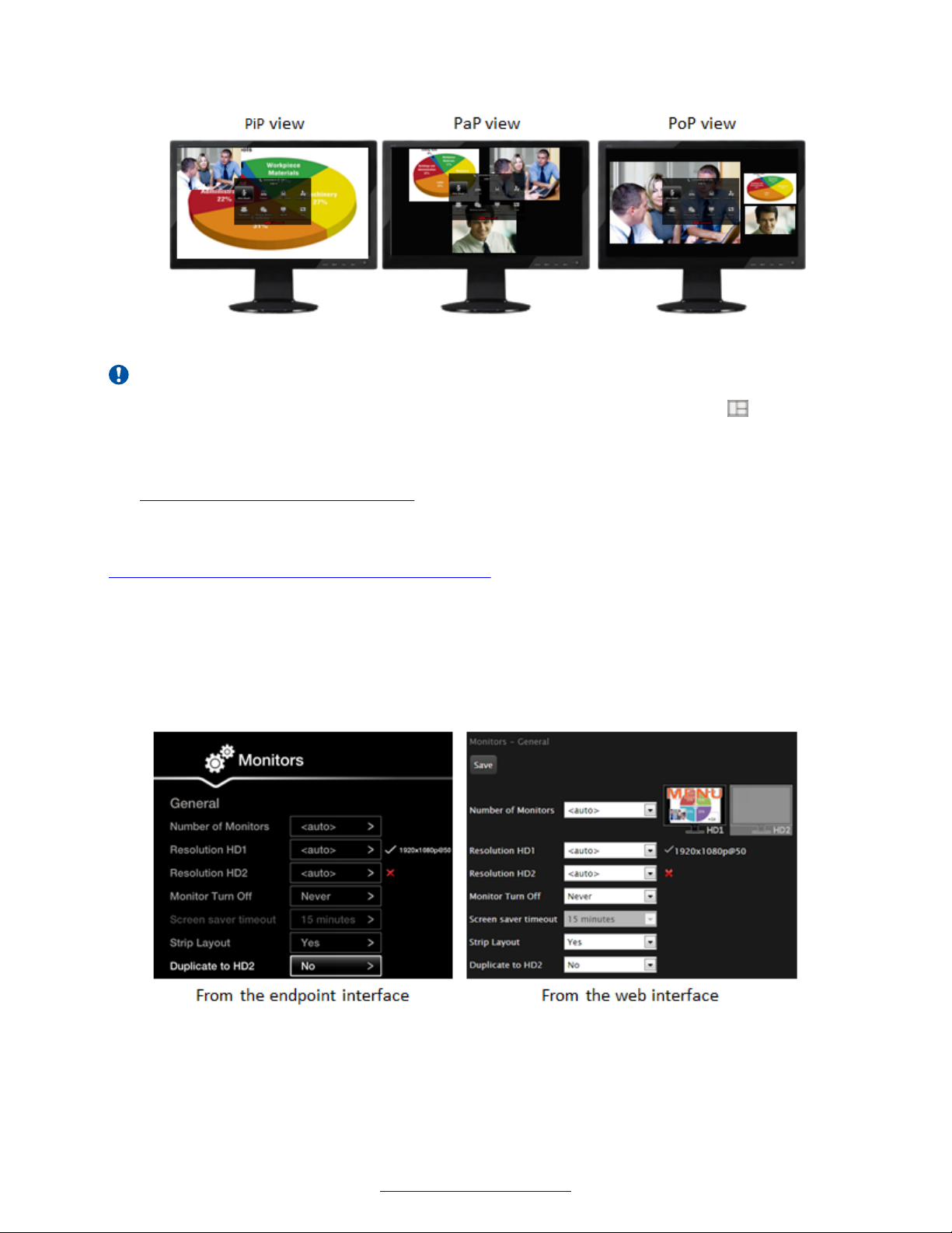
Configuring Monitors
Figure 64: Single monitor video layouts with presentation
Important:
To reset the number of monitors to the default <auto > setting, press layouts and then 0 on
the XT Remote Control Unit. The system then automatically detects the number of connected
monitors.
If your monitor crops the edges of the image shown in their displays, adjust it as described in
Resolving Monitor Display Problems on page 185.
Before you begin
If configuring from the endpoint, you must first enable advanced configuration, as described in
Enabling Advanced Maintenance on the XT Series on page 112.
Procedure
1. Access the monitor settings. From the XT Series web interface, select Administrator
settings > I/O connections > Monitor. From the endpoint's main menu, select Configure >
Advanced > I/O connections > Monitor.
2. Select General to access the general settings.
Figure 65: Configuring the general monitor settings from the web interface
3. Configure the general settings:
April 2015 Avaya Scopia® XT Series Deployment Guide 97
Comments? [email protected]
Page 98
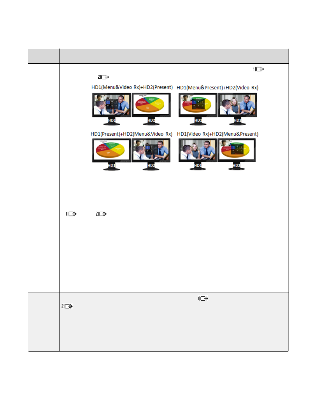
Initial Configuration of the XT Series
Table 19: Configuring general monitor settings
Field
Name
Number of
monitors
Description
Activate the HDMI ports on the XT Codec Unit which connect to a monitor: the HD1 port
and/or the HD2 port.
Figure 66: Dual monitor video layouts with presentation
• <auto > indicates the system automatically detects the number of connected monitors
(recommended).
Resolution
HD1/HD2
• HD1/HD2 forces the unit to accept input only from a single monitor connected to either HD1
or HD2 . If you connect a second monitor it would appear blank, unless you select
Duplicate to HD2.
• HD1 (Menu & Video Rx) + HD2 (Present) uses both monitor connections, where the main
monitor displays system menus and remote video, while shared content is on the auxiliary
monitor. This is the default mode with two connected monitors set to <auto > .
• HD1 (Menu & Present) + HD2 (Video Rx) uses both monitor connections, with system menus
and PC content on the main monitor, while remote video is on the auxiliary monitor.
• HD1 (Present) + HD2 (Menu & Video Rx) uses both monitor connections, with system menus
and remote video on the auxiliary monitor, while shared content is on the main monitor.
• HD1 (Video Rx) + HD2 (Menu & Present) uses both monitor connections, with system menus
and shared content on the auxiliary monitor, while remote video is on the main monitor.
Defines the resolution of the connected main monitor (HD1 ) and auxiliary monitor (HD2
).
• <auto > sets 1080p as the default settings for both monitors.
• 1080p forces 1080p resolution at 25, 30, 50 or 60 frames per second (fps) if the monitor
supports it.
• 720p forces 720p resolution at 50 or 60fps if the monitor supports it, even if the received
resolution is higher.
Table continues…
98 Avaya Scopia
®
XT Series Deployment Guide April 2015
Comments? [email protected]
Page 99

Configuring Monitors
Field
Name
Gallery
Layout
Duplicate
to HD2
4. From the web interface only, select Save.
5. Configure the video layout. Select Monitor > PIP-PaP-PoP.
Description
Select Yes to add availability of video layouts which mix video and presentation in the same
stream and display them on the same screen, so participant images appear to the side or
underneath the presentation. This is displayed when you have just one monitor, managed by
Scopia® Management, and the meeting hosted on the Scopia® Elite MCU.
Select Yes if you have two monitors and you want the monitor connected to HD2 to display
the same as HD1 but without system menus.
Figure 67: Setting the video layout
6. Enter the field values as described in
Table 20: Configuring the video layout
Field Name Description
Multi Image Mode Enable PIP, PaP or PoP video layouts, depending on the number of video streams
available (see Figure 64: Single monitor video layouts with presentation on page 97).
• <auto > enables PiP, PaP or PoP only when the number of video streams is greater
than the number of available monitors. The order of the video streams is set
automatically, with precedence to the presentation video streams.
• On always enables PiP, PaP or PoP when at least two video streams are used.
When you are using two monitors, PIP can be forced only if there are at least three
different video streams.
• Off always disables PIP, PaP and PoP.
Multi Image Type Limit the video layouts available to users:
•
auto enables PIP, PaP and PoP layouts. Press the Layouts key to switch
between PIP, PaP and PoP.
• PIP enables only PiP.
Table 20: Configuring the video layout on page 99.
Table continues…
April 2015 Avaya Scopia® XT Series Deployment Guide 99
Comments? [email protected]
Page 100
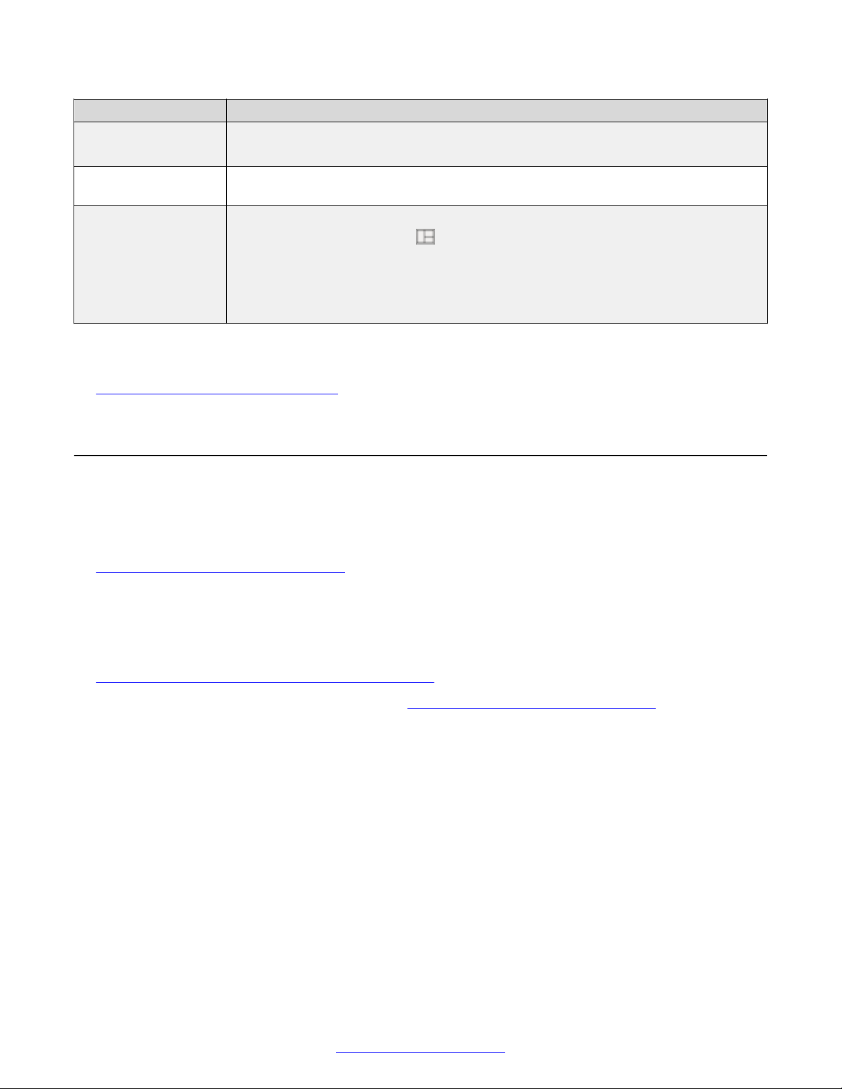
Initial Configuration of the XT Series
Field Name Description
• PaP enables only PaP.
• PoP enables only PoP.
PIP - Position Set the position of the small overlapped image on the monitor: upper left, upper right,
lower left, or lower right.
PIP - Rotation Enables/disables image rotation and controls the direction in which the image rotates.
End-users press the Layouts key to activate image rotation (if enabled).
• Fixed blocks image rotation (not available for Scopia® XT Executive).
• Clockwise rotates the overlapped image clockwise.
• Counterclockwise rotates the overlapped image anti-clockwise.
7. From the web interface only, select Save.
Related Links
Initial Configuration of the XT Series on page 78
Configuring Cameras
About this task
Configure the camera depending on the type of camera, its functionality, and how it is connected to
the XT Series. For more information about connecting your camera to the XT Codec Unit, see
Connecting Cameras or DVD players on page 48.
In this section, first define which camera is the unit's default camera and other general properties,
then define each camera's settings by configuring the port connection.
Before you begin
If configuring from the endpoint, you must first enable advanced configuration, as described in
Enabling Advanced Maintenance on the XT Series on page 112.
Connect the video equipment, as described in Connecting Cameras or DVD players on page 48.
Procedure
1. Access the camera settings. From the XT Series web interface, select Administrator
settings > I/O connections > Cameras > General. From the endpoint's main menu, select
Configure > Advanced > I/O connections > Cameras > General.
100 Avaya Scopia
®
XT Series Deployment Guide April 2015
Comments? [email protected]
 Loading...