

Avaya Scopia Elite MCU 6105, Scopia Elite MCU 6110, Scopia Elite MCU 6120, Scopia Elite MCU 6140 Installation Manual
Avaya Scopia® Elite 6000 Series MCU
Installation Guide
Release 8.3.2
For Solution 8.3.2
Issue 2
February 2016

©
2014-2016, Avaya, Inc.
All Rights Reserved.
Notice
While reasonable efforts have been made to ensure that the
information in this document is complete and accurate at the time of
printing, Avaya assumes no liability for any errors. Avaya reserves
the right to make changes and corrections to the information in this
document without the obligation to notify any person or organization
of such changes.
Documentation disclaimer
“Documentation” means information published by Avaya in varying
mediums which may include product information, operating
instructions and performance specifications that Avaya may generally
make available to users of its products and Hosted Services.
Documentation does not include marketing materials. Avaya shall not
be responsible for any modifications, additions, or deletions to the
original published version of documentation unless such
modifications, additions, or deletions were performed by Avaya. End
User agrees to indemnify and hold harmless Avaya, Avaya's agents,
servants and employees against all claims, lawsuits, demands and
judgments arising out of, or in connection with, subsequent
modifications, additions or deletions to this documentation, to the
extent made by End User.
Link disclaimer
Avaya is not responsible for the contents or reliability of any linked
websites referenced within this site or documentation provided by
Avaya. Avaya is not responsible for the accuracy of any information,
statement or content provided on these sites and does not
necessarily endorse the products, services, or information described
or offered within them. Avaya does not guarantee that these links will
work all the time and has no control over the availability of the linked
pages.
Warranty
Avaya provides a limited warranty on Avaya hardware and software.
Refer to your sales agreement to establish the terms of the limited
warranty. In addition, Avaya’s standard warranty language, as well as
information regarding support for this product while under warranty is
available to Avaya customers and other parties through the Avaya
Support website:
https://support.avaya.com/helpcenter/
getGenericDetails?detailId=C20091120112456651010 under the link
“Warranty & Product Lifecycle” or such successor site as designated
by Avaya. Please note that if You acquired the product(s) from an
authorized Avaya Channel Partner outside of the United States and
Canada, the warranty is provided to You by said Avaya Channel
Partner and not by Avaya.
“Hosted Service” means a hosted service subscription that You
acquire from either Avaya or an authorized Avaya Channel Partner
(as applicable) and which is described further in Hosted SAS or other
service description documentation regarding the applicable hosted
service. If You purchase a Hosted Service subscription, the foregoing
limited warranty may not apply but You may be entitled to support
services in connection with the Hosted Service as described further
in your service description documents for the applicable Hosted
Service. Contact Avaya or Avaya Channel Partner (as applicable) for
more information.
Hosted Service
THE FOLLOWING APPLIES IF YOU PURCHASE A HOSTED
SERVICE SUBSCRIPTION FROM AVAYA OR AN AVAYA
CHANNEL PARTNER (AS APPLICABLE), THE TERMS OF USE
FOR HOSTED SERVICES ARE AVAILABLE ON THE AVAYA
WEBSITE,
HTTPS://SUPPORT.AVAYA.COM/LICENSEINFO
UNDER THE LINK “Avaya Terms of Use for Hosted Services” OR
SUCH SUCCESSOR SITE AS DESIGNATED BY AVAYA, AND ARE
APPLICABLE TO ANYONE WHO ACCESSES OR USES THE
HOSTED SERVICE. BY ACCESSING OR USING THE HOSTED
SERVICE, OR AUTHORIZING OTHERS TO DO SO, YOU, ON
BEHALF OF YOURSELF AND THE ENTITY FOR WHOM YOU ARE
DOING SO (HEREINAFTER REFERRED TO INTERCHANGEABLY
AS “YOU” AND “END USER”), AGREE TO THE TERMS OF USE. IF
YOU ARE ACCEPTING THE TERMS OF USE ON BEHALF A
COMPANY OR OTHER LEGAL ENTITY, YOU REPRESENT THAT
YOU HAVE THE AUTHORITY TO BIND SUCH ENTITY TO THESE
TERMS OF USE. IF YOU DO NOT HAVE SUCH AUTHORITY, OR
IF YOU DO NOT WISH TO ACCEPT THESE TERMS OF USE, YOU
MUST NOT ACCESS OR USE THE HOSTED SERVICE OR
AUTHORIZE ANYONE TO ACCESS OR USE THE HOSTED
SERVICE. YOUR USE OF THE HOSTED SERVICE SHALL BE
LIMITED BY THE NUMBER AND TYPE OF LICENSES
PURCHASED UNDER YOUR CONTRACT FOR THE HOSTED
SERVICE, PROVIDED, HOWEVER, THAT FOR CERTAIN HOSTED
SERVICES IF APPLICABLE, YOU MAY HAVE THE OPPORTUNITY
TO USE FLEX LICENSES, WHICH WILL BE INVOICED
ACCORDING TO ACTUAL USAGE ABOVE THE CONTRACT
LICENSE LEVEL. CONTACT AVAYA OR AVAYA’S CHANNEL
PARTNER FOR MORE INFORMATION ABOUT THE LICENSES
FOR THE APPLICABLE HOSTED SERVICE, THE AVAILABILITY
OF ANY FLEX LICENSES (IF APPLICABLE), PRICING AND
BILLING INFORMATION, AND OTHER IMPORTANT
INFORMATION REGARDING THE HOSTED SERVICE.
Licenses
THE SOFTWARE LICENSE TERMS AVAILABLE ON THE AVAYA
WEBSITE,
HTTPS://SUPPORT.AVAYA.COM/LICENSEINFO,
UNDER THE LINK “AVAYA SOFTWARE LICENSE TERMS (Avaya
Products)” OR SUCH SUCCESSOR SITE AS DESIGNATED BY
AVAYA, ARE APPLICABLE TO ANYONE WHO DOWNLOADS,
USES AND/OR INSTALLS AVAYA SOFTWARE, PURCHASED
FROM AVAYA INC., ANY AVAYA AFFILIATE, OR AN AVAYA
CHANNEL PARTNER (AS APPLICABLE) UNDER A COMMERCIAL
AGREEMENT WITH AVAYA OR AN AVAYA CHANNEL PARTNER.
UNLESS OTHERWISE AGREED TO BY AVAYA IN WRITING,
AVAYA DOES NOT EXTEND THIS LICENSE IF THE SOFTWARE
WAS OBTAINED FROM ANYONE OTHER THAN AVAYA, AN
AVAYA AFFILIATE OR AN AVAYA CHANNEL PARTNER; AVAYA
RESERVES THE RIGHT TO TAKE LEGAL ACTION AGAINST YOU
AND ANYONE ELSE USING OR SELLING THE SOFTWARE
WITHOUT A LICENSE. BY INSTALLING, DOWNLOADING OR
USING THE SOFTWARE, OR AUTHORIZING OTHERS TO DO SO,
YOU, ON BEHALF OF YOURSELF AND THE ENTITY FOR WHOM
YOU ARE INSTALLING, DOWNLOADING OR USING THE
SOFTWARE (HEREINAFTER REFERRED TO
INTERCHANGEABLY AS “YOU” AND “END USER”), AGREE TO
THESE TERMS AND CONDITIONS AND CREATE A BINDING
CONTRACT BETWEEN YOU AND AVAYA INC. OR THE
APPLICABLE AVAYA AFFILIATE (“AVAYA”).
Avaya grants You a license within the scope of the license types
described below, with the exception of Heritage Nortel Software, for
which the scope of the license is detailed below. Where the order
documentation does not expressly identify a license type, the
applicable license will be a Designated System License. The
applicable number of licenses and units of capacity for which the
license is granted will be one (1), unless a different number of
licenses or units of capacity is specified in the documentation or other
materials available to You. “Software” means computer programs in
object code, provided by Avaya or an Avaya Channel Partner,
whether as stand-alone products, pre-installed on hardware products,
and any upgrades, updates, patches, bug fixes, or modified versions
thereto. “Designated Processor” means a single stand-alone
computing device. “Server” means a Designated Processor that
hosts a software application to be accessed by multiple users.
“Instance” means a single copy of the Software executing at a
particular time: (i) on one physical machine; or (ii) on one deployed
software virtual machine (“VM”) or similar deployment.
License type(s)
Designated System(s) License (DS). End User may install and use
each copy or an Instance of the Software only on a number of
Designated Processors up to the number indicated in the order.
Avaya may require the Designated Processor(s) to be identified in
the order by type, serial number, feature key, Instance, location or
other specific designation, or to be provided by End User to Avaya
through electronic means established by Avaya specifically for this
purpose.
Concurrent User License (CU). End User may install and use the
Software on multiple Designated Processors or one or more Servers,
so long as only the licensed number of Units are accessing and using
the Software at any given time. A “Unit” means the unit on which
Avaya, at its sole discretion, bases the pricing of its licenses and can
be, without limitation, an agent, port or user, an e-mail or voice mail

account in the name of a person or corporate function (e.g.,
webmaster or helpdesk), or a directory entry in the administrative
database utilized by the Software that permits one user to interface
with the Software. Units may be linked to a specific, identified Server
or an Instance of the Software.
Database License (DL). End User may install and use each copy or
an Instance of the Software on one Server or on multiple Servers
provided that each of the Servers on which the Software is installed
communicates with no more than one Instance of the same
database.
CPU License (CP). End User may install and use each copy or
Instance of the Software on a number of Servers up to the number
indicated in the order provided that the performance capacity of the
Server(s) does not exceed the performance capacity specified for the
Software. End User may not re-install or operate the Software on
Server(s) with a larger performance capacity without Avaya’s prior
consent and payment of an upgrade fee.
Named User License (NU). You may: (i) install and use each copy or
Instance of the Software on a single Designated Processor or Server
per authorized Named User (defined below); or (ii) install and use
each copy or Instance of the Software on a Server so long as only
authorized Named Users access and use the Software. “Named
User”, means a user or device that has been expressly authorized by
Avaya to access and use the Software. At Avaya’s sole discretion, a
“Named User” may be, without limitation, designated by name,
corporate function (e.g., webmaster or helpdesk), an e-mail or voice
mail account in the name of a person or corporate function, or a
directory entry in the administrative database utilized by the Software
that permits one user to interface with the Software.
Shrinkwrap License (SR). You may install and use the Software in
accordance with the terms and conditions of the applicable license
agreements, such as “shrinkwrap” or “clickthrough” license
accompanying or applicable to the Software (“Shrinkwrap License”).
Heritage Nortel Software
“Heritage Nortel Software” means the software that was acquired by
Avaya as part of its purchase of the Nortel Enterprise Solutions
Business in December 2009. The Heritage Nortel Software is the
software contained within the list of Heritage Nortel Products located
https://support.avaya.com/LicenseInfo under the link “Heritage
at
Nortel Products” or such successor site as designated by Avaya. For
Heritage Nortel Software, Avaya grants Customer a license to use
Heritage Nortel Software provided hereunder solely to the extent of
the authorized activation or authorized usage level, solely for the
purpose specified in the Documentation, and solely as embedded in,
for execution on, or for communication with Avaya equipment.
Charges for Heritage Nortel Software may be based on extent of
activation or use authorized as specified in an order or invoice.
Copyright
Except where expressly stated otherwise, no use should be made of
materials on this site, the Documentation, Software, Hosted Service,
or hardware provided by Avaya. All content on this site, the
documentation, Hosted Service, and the product provided by Avaya
including the selection, arrangement and design of the content is
owned either by Avaya or its licensors and is protected by copyright
and other intellectual property laws including the sui generis rights
relating to the protection of databases. You may not modify, copy,
reproduce, republish, upload, post, transmit or distribute in any way
any content, in whole or in part, including any code and software
unless expressly authorized by Avaya. Unauthorized reproduction,
transmission, dissemination, storage, and or use without the express
written consent of Avaya can be a criminal, as well as a civil offense
under the applicable law.
Virtualization
The following applies if the product is deployed on a virtual machine.
Each product has its own ordering code and license types. Note that
each Instance of a product must be separately licensed and ordered.
For example, if the end user customer or Avaya Channel Partner
would like to install two Instances of the same type of products, then
two products of that type must be ordered.
Third Party Components
“Third Party Components” mean certain software programs or
portions thereof included in the Software or Hosted Service may
contain software (including open source software) distributed under
third party agreements (“Third Party Components”), which contain
terms regarding the rights to use certain portions of the Software
(“Third Party Terms”). As required, information regarding distributed
Linux OS source code (for those products that have distributed Linux
OS source code) and identifying the copyright holders of the Third
Party Components and the Third Party Terms that apply is available
in the products, Documentation or on Avaya’s website at:
support.avaya.com/Copyright or such successor site as designated
by Avaya. The open source software license terms provided as Third
Party Terms are consistent with the license rights granted in these
Software License Terms, and may contain additional rights benefiting
You, such as modification and distribution of the open source
software. The Third Party Terms shall take precedence over these
Software License Terms, solely with respect to the applicable Third
Party Components to the extent that these Software License Terms
impose greater restrictions on You than the applicable Third Party
Terms.
The following applies if the H.264 (AVC) codec is distributed with the
product. THIS PRODUCT IS LICENSED UNDER THE AVC PATENT
PORTFOLIO LICENSE FOR THE PERSONAL USE OF A
CONSUMER OR OTHER USES IN WHICH IT DOES NOT RECEIVE
REMUNERATION TO (i) ENCODE VIDEO IN COMPLIANCE WITH
THE AVC STANDARD (“AVC VIDEO”) AND/OR (ii) DECODE AVC
VIDEO THAT WAS ENCODED BY A CONSUMER ENGAGED IN A
PERSONAL ACTIVITY AND/OR WAS OBTAINED FROM A VIDEO
PROVIDER LICENSED TO PROVIDE AVC VIDEO. NO LICENSE IS
GRANTED OR SHALL BE IMPLIED FOR ANY OTHER USE.
ADDITIONAL INFORMATION MAY BE OBTAINED FROM MPEG
LA, L.L.C. SEE
Service Provider
THE FOLLOWING APPLIES TO AVAYA CHANNEL PARTNER’S
HOSTING OF AVAYA PRODUCTS OR SERVICES. THE PRODUCT
OR HOSTED SERVICE MAY USE THIRD PARTY COMPONENTS
SUBJECT TO THIRD PARTY TERMS AND REQUIRE A SERVICE
PROVIDER TO BE INDEPENDENTLY LICENSED DIRECTLY
FROM THE THIRD PARTY SUPPLIER. AN AVAYA CHANNEL
PARTNER’S HOSTING OF AVAYA PRODUCTS MUST BE
AUTHORIZED IN WRITING BY AVAYA AND IF THOSE HOSTED
PRODUCTS USE OR EMBED CERTAIN THIRD PARTY
SOFTWARE, INCLUDING BUT NOT LIMITED TO MICROSOFT
SOFTWARE OR CODECS, THE AVAYA CHANNEL PARTNER IS
REQUIRED TO INDEPENDENTLY OBTAIN ANY APPLICABLE
LICENSE AGREEMENTS, AT THE AVAYA CHANNEL PARTNER’S
EXPENSE, DIRECTLY FROM THE APPLICABLE THIRD PARTY
SUPPLIER.
WITH RESPECT TO CODECS, IF THE AVAYA CHANNEL
PARTNER IS HOSTING ANY PRODUCTS THAT USE OR EMBED
THE G.729 CODEC, H.264 CODEC, OR H.265 CODEC, THE
AVAYA CHANNEL PARTNER ACKNOWLEDGES AND AGREES
THE AVAYA CHANNEL PARTNER IS RESPONSIBLE FOR ANY
AND ALL RELATED FEES AND/OR ROYALTIES. THE G.729
CODEC IS LICENSED BY SIPRO LAB TELECOM INC. SEE
WWW.SIPRO.COM/CONTACT.HTML. THE H.264 (AVC) CODEC IS
LICENSED UNDER THE AVC PATENT PORTFOLIO LICENSE FOR
THE PERSONAL USE OF A CONSUMER OR OTHER USES IN
WHICH IT DOES NOT RECEIVE REMUNERATION TO: (I)
ENCODE VIDEO IN COMPLIANCE WITH THE AVC STANDARD
(“AVC VIDEO”) AND/OR (II) DECODE AVC VIDEO THAT WAS
ENCODED BY A CONSUMER ENGAGED IN A PERSONAL
ACTIVITY AND/OR WAS OBTAINED FROM A VIDEO PROVIDER
LICENSED TO PROVIDE AVC VIDEO. NO LICENSE IS GRANTED
OR SHALL BE IMPLIED FOR ANY OTHER USE. ADDITIONAL
INFORMATION FOR H.264 (AVC) AND H.265 (HEVC) CODECS
MAY BE OBTAINED FROM MPEG LA, L.L.C. SEE
WWW.MPEGLA.COM.
Compliance with Laws
Customer acknowledges and agrees that it is responsible for
complying with any applicable laws and regulations, including, but not
limited to laws and regulations related to call recording, data privacy,
intellectual property, trade secret, fraud, and music performance
rights, in the country or territory where the Avaya product is used.
HTTP://WWW.MPEGLA.COM.
https://
HTTP://

Preventing Toll Fraud
“Toll Fraud” is the unauthorized use of your telecommunications
system by an unauthorized party (for example, a person who is not a
corporate employee, agent, subcontractor, or is not working on your
company's behalf). Be aware that there can be a risk of Toll Fraud
associated with your system and that, if Toll Fraud occurs, it can
result in substantial additional charges for your telecommunications
services.
Avaya Toll Fraud intervention
If You suspect that You are being victimized by Toll Fraud and You
need technical assistance or support, call Technical Service Center
Toll Fraud Intervention Hotline at +1-800-643-2353 for the United
States and Canada. For additional support telephone numbers, see
the Avaya Support website:
successor site as designated by Avaya.
Security Vulnerabilities
Information about Avaya’s security support policies can be found in
the Security Policies and Support section of https://
support.avaya.com/security.
Suspected Avaya product security vulnerabilities are handled per the
Avaya Product Security Support Flow (https://
support.avaya.com/css/P8/documents/100161515).
Downloading Documentation
For the most current versions of Documentation, see the Avaya
Support website:
as designated by Avaya.
Contact Avaya Support
See the Avaya Support website:
product or Hosted Service notices and articles, or to report a problem
with your Avaya product or Hosted Service. For a list of support
telephone numbers and contact addresses, go to the Avaya Support
website: https://support.avaya.com (or such successor site as
designated by Avaya), scroll to the bottom of the page, and select
Contact Avaya Support.
Trademarks
The trademarks, logos and service marks (“Marks”) displayed in this
site, the Documentation, Hosted Service(s), and product(s) provided
by Avaya are the registered or unregistered Marks of Avaya, its
affiliates, or other third parties. Users are not permitted to use such
Marks without prior written consent from Avaya or such third party
which may own the Mark. Nothing contained in this site, the
Documentation, Hosted Service(s) and product(s) should be
construed as granting, by implication, estoppel, or otherwise, any
license or right in and to the Marks without the express written
permission of Avaya or the applicable third party.
Avaya is a registered trademark of Avaya Inc.
All non-Avaya trademarks are the property of their respective owners.
Linux® is the registered trademark of Linus Torvalds in the U.S. and
other countries.
https://support.avaya.com, or such successor site
https://support.avaya.com or such
https://support.avaya.com for


Contents
Chapter 1: About the Avaya Scopia® Elite MCU.................................................................... 8
About Avaya Scopia® Elite MCU.............................................................................................. 8
Minimum Requirements and Specifications............................................................................. 12
Document changes since last issue........................................................................................ 14
Chapter 2: Planning your MCU Deployment........................................................................ 15
Deploying Redundant MCUs.................................................................................................. 15
Planning a Centralized or Distributed Topology (Cascading) for MCU........................................ 16
Planning Network Redundancy or IP Separation (Dual NIC)..................................................... 18
About the Capacity of the MCU.............................................................................................. 19
Ports to Open for the Scopia® Elite 6000 Series MCU.............................................................. 21
Chapter 3: Preparing the MCU Setup.................................................................................... 25
Checking Site Suitability......................................................................................................... 25
Unpacking the Device............................................................................................................ 25
Inspecting for Damage........................................................................................................... 26
Chapter 4: Setting up the Device........................................................................................... 28
Adding a Power Supply Unit to the MCU................................................................................. 28
Mounting the Device on to the Rack........................................................................................ 30
Preparing the Rack and Rails for Mounting the Device....................................................... 30
Mounting the Outer Rails on to the Rack........................................................................... 33
Mounting the Device on to the Outer Rails......................................................................... 37
Connecting Cables to the Device............................................................................................ 41
Configuring the Device IP Addresses...................................................................................... 43
Chapter 5: Performing Initial Configuration......................................................................... 48
Accessing the MCU Administrator Web Interface..................................................................... 48
Changing a User Password.................................................................................................... 49
Adding a License to the MCU................................................................................................. 50
Changing the Default MCU Meeting Type................................................................................ 51
Setting the MCU Interface Languages..................................................................................... 52
About Supported Languages............................................................................................ 52
Setting the MCU User Interface Language......................................................................... 53
Setting a Text Overlay Language...................................................................................... 54
Configuring IP Separation (Dual NIC) on the Device................................................................. 55
Configuring Network Protocols for the MCU............................................................................. 60
Connecting the MCU to the Gatekeeper............................................................................ 61
Configuring SIP Server Settings....................................................................................... 62
Configuring Ports on All Models of the Scopia® Elite MCU........................................................ 65
Configuring the UDP Port Ranges for RTP/RTCP on the Scopia® Elite MCU....................... 66
Configuring the TCP Port Range for H.245 on the Scopia® Elite MCU................................. 67
Configuring the HTTP Port on the Scopia® Elite MCU........................................................ 68
February 2016 Avaya Scopia® Elite 6000 Series MCU Installation Guide 6
Comments on this document? infodev@avaya.com

Contents
Configuring the UDP Port for RAS on the Scopia® Elite MCU............................................. 69
Configuring the UDP Port for the Gatekeeper on the Scopia® Elite MCU............................. 70
Configuring the TCP Port Q.931 on the Scopia® Elite MCU................................................ 70
Configuring the TCP/UDP/TLS Port for SIP on the Scopia® Elite MCU................................ 71
Configuring the TCP Port Range for SIP BFCP on the Scopia® Elite MCU........................... 72
Configuring Security Access Levels for the Scopia® Elite MCU................................................. 73
Verifying the MCU Installation................................................................................................ 74
Glossary................................................................................................................................... 77
February 2016 Avaya Scopia® Elite 6000 Series MCU Installation Guide 7
Comments on this document? infodev@avaya.com

Chapter 1: About the Avaya Scopia® Elite
MCU
The Scopia® Elite MCU is Scopia® Solution’s flagship platform for high definition multi-party
videoconferencing.
The MCU supports communications in the board room, at the desktop, in the home, or on the road
over wireless.
Related links
About Avaya Scopia® Elite MCU on page 8
Minimum Requirements and Specifications on page 12
About Avaya Scopia® Elite MCU
The Scopia® Elite MCU is Scopia® Solution’s flagship platform for high definition multi-party
videoconferencing.
An MCU, or Multipoint Control Unit, connects several endpoints to a single videoconference. It
manages the audio mixing and creates the video layouts, adjusting the output to suit each
endpoint's capabilities.
The MCU harnesses revolutionary processing power for the most demanding videoconferencing
applications using the latest DSP technologies. For an uncompromised videoconferencing
experience, the MCU supports dual channels of Full HD 1080p at 60 frames per second for video
and content, H.264 High Profile for bandwidth efficiency, H.264 Scalable Video Coding (SVC) for
high network error resiliency, and full support for many telepresence systems.
With the MCU, each videoconference participant receives a quality experience optimized to their
individual capabilities, from wireless mobile devices to HD room systems and immersive
telepresence systems. The MCU leads in video interoperability, working with the broadest range of
video systems on the market from leading UC clients to mobile devices and telepresence systems.
The MCU also features a patented, distributed architecture approach known as the Virtual MCU or
cascaded videoconferences, which brings unparalleled scalability to its superb videoconferencing
experience.
The MCU's feature list includes:
• Revolutionary video processing power
February 2016 Avaya Scopia® Elite 6000 Series MCU Installation Guide 8
Comments on this document? infodev@avaya.com

About Avaya Scopia® Elite MCU
The MCU brings unmatched power and capacity in a single unit, enabling dual-channel Full HD
1080p resolution at 60 frames per second for video and content, simultaneous H.264 High
Profile and H.264 SVC, and support for multi-stream telepresence.
• Dynamic resource allocation
A meeting can support a mix of SD and HD users, making most efficient use of available
resources. Video and audio processing is carried out per user rather than per meeting, with
resolutions ranging from CIF to 1080p in the same meeting. Each user connects using unique,
optimized audio and video settings to enjoy the best audio and video quality supported by their
endpoint and network, without affecting the other participants in a conference.
• Intuitive and easy to use
Video menus make it easy to set up or enter a videoconference, and the intuitive web interface
makes administration easy.
• Massive scalability
The Virtual MCU enables a unique scalability in both local and distributed architectures to
combine the capacity of multiple MCU devices in the same meeting. The number of supported
connections depends on your license.
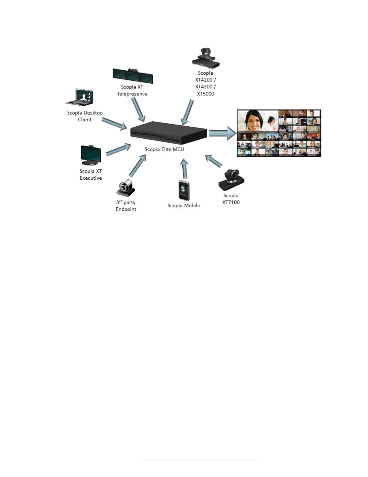
• Seamless interoperability
The MCU is built on the solid foundation of our H.323 and SIP software, ensuring full
compliance and broad-ranging interoperability with IP, ISDN, and 3G endpoints. It also enables
H.323 and SIP endpoints to collaborate in the same videoconference. See
Figure 1: Endpoints
in the same videoconference on page 10.
February 2016 Avaya Scopia® Elite 6000 Series MCU Installation Guide 9
Comments on this document? infodev@avaya.com
About the Avaya Scopia® Elite MCU
Figure 1: Endpoints in the same videoconference
The MCU also easily integrates telepresence systems with regular videoconferencing systems,
even within the same meeting. It is compatible with telepresence systems from Cisco,
Tandberg, Polycom, and LifeSize/Logitech.
When used with Scopia® Solution gateways, the deployment can even add ISDN, V.35 and
other endpoints to the same meeting.
• Video quality
The MCU delivers enterprise quality video and audio processing, using latest industry
standards including state-of-the-art DSP hardware and software. This video quality is
supported by:
- SVC error resiliency for unmanaged networks using Temporal Scalability and Forward Error
Correction (FEC).
Forward Error Correction (FEC) is a proactive method of sending redundant information in
the video stream to preempt quality degradation. SVC extends the H.264 codec standard to
dramatically increase error resiliency and video quality without the need for higher
bandwidth.
- Frame rates can reach 60 frames per second, ensuring smooth video movement.
- A wide choice of video layouts
February 2016 Avaya Scopia® Elite 6000 Series MCU Installation Guide 10
Comments on this document? infodev@avaya.com

About Avaya Scopia® Elite MCU
- Bitrate (data speed) of up to 12 megabits per second on each stream without affecting
capacity. Bitrate is the speed of data flow. Higher video resolutions require higher bitrates to
ensure the video is constantly updated, thereby maintaining smooth motion.
• Audio quality
The MCU integrates Voice Activity Detection (VAD) to determine the active speaker and filter
out background noise from participants. The MCU also improves audio quality with AGC.
Automatic Gain Control (AGC) smooths audio signals through normalization, by lowering
sounds which are too strong and strengthening sounds which are too weak.
• Personalized video layouts per meeting or per participant
As an administrator you can choose from 26 video layouts for all participants, or each
participant can customize their own view. You can view up to 28 participants on your screen. A
video layout is the arrangement of participant images as they appear on the monitor in a
videoconference. If the meeting includes a presentation, a layout can also refer to the
arrangement of the presentation image together with the meeting participants.
The MCU supports sharing presentations and other content via SIP (using the BFCP standard)
and H.323 (using the H.239 standard). A user can connect to a meeting from either type of
endpoint to share content such as presentations, spreadsheets, documents, and movies.
The MCU supports an additional set of layouts to optimize screen space during content sharing
on single-screen endpoints. With this feature, endpoints with proprietary content sharing
protocols such as Avaya Flare Experience or Microsoft Lync can simultaneously display
content and participants.
• Security and privacy
The MCU can encrypt communications with endpoints to create secure connections with H.
235-based encryption for H.323 endpoints and SRTP and TLS encryption for SIP endpoints.
In addition, the MCU features administrator and operator password protection for accessing the
web interface. It also features optional PIN protection for joining a videoconference, and
additional PIN protection for moderator control.
• Dual NIC: IP separation or network redundancy
You can use the two network ports of the MCU in one of the following ways:
- Network redundancy cuts downtime and provides a cost-effective, uninterrupted service. If
the first NIC fails during a videoconference, network traffic is automatically routed to the
second NIC without affecting current calls on the MCU.
- IP separation enhances security within the enterprise by routing media and management
traffic to two different subnets.
• Intuitive web-based management
You can configure the MCU through an intuitive web interface offering easy, high-level
administrative flexibility for an enhanced user experience.
• In-meeting indicators
A range of messages and icons are displayed on the endpoint during meetings as events
occur. For example, participants are notified when someone joins or leaves the meeting.
February 2016 Avaya Scopia® Elite 6000 Series MCU Installation Guide 11
Comments on this document? infodev@avaya.com

About the Avaya Scopia® Elite MCU
• Easy creation of logs for Customer Support
You can easily create a file containing logs and settings which you can send to Customer
Support for troubleshooting.
• Interactive Voice Response (IVR) messages
The MCU includes pre-recorded greetings to participants and announcements as each new
participant joins a meeting. You can record messages to provide custom greetings and
announcements, but typically Avaya Scopia® Management supplies these messages across all
MCUs in the organization.
• SIP Firewall traversal compatibilities
The MCU is fully interoperable with third-party Session Border Controllers (SBC), which
increases compatibility and dexterity with SIP endpoints that join remotely.
Related links
About the Avaya Scopia® Elite MCU on page 8
Minimum Requirements and Specifications
This section details the system specifications of the MCU you purchased. Refer to this data when
preparing system setup and afterwards as a means of verifying that the environment still complies
with these requirements.
Hardware requirements
Table 1: Physical device specifications on page 12 refers to the physical details of the device.
Table 1: Physical device specifications
Scopia
and 6120
System power requirements
Input 100-240 VAC, 50/60 Hz 100-240 VAC, 50/60 Hz with hot-
AC Input 600W output @ 100-240V, 7.5A,
50-60Hz
Maximum power consumption at
35°C
200W, 250VA (682 BTU/h) 360W, 450VA (1228 BTU/h)
®
Elite MCU 6105, 6110
Scopia® Elite MCU 6140
swap redundant AC power supply
and feed (optional)
1000W output @ 100-120V,
12-10A, 50-60Hz
1200W output @ 120-140V,
12-10A, 50-60Hz
1800W output @ 200-240V,
10-8.5A, 50-60Hz
Table continues…
February 2016 Avaya Scopia® Elite 6000 Series MCU Installation Guide 12
Comments on this document? infodev@avaya.com
Minimum Requirements and Specifications
Scopia® Elite MCU 6105, 6110
and 6120
Environmental requirements
Operating temperature 10°C to 35°C (50°F to 95°F)
Relative humidity 5% to 90% non-condensing
Storage and transit temperature -40°C to 70°C (-40°F to 158°F), ambient
Acoustics Low noise fan speed control
Physical requirements
Dimensions Width: 437mm (17.2"); height:
43mm (1.7"); depth 664mm (26.1")
Approximate net weight 11kg (24.25lbs) 14.5kg (32lbs) with one power
Approximate gross weight (with
packaging)
Rack mounting 19-inch rack-mountable with flanges
21kg (46.3lbs) 23kg (50.7lbs)
Scopia® Elite MCU 6140
Width: 437mm (17.2"); height:
43mm (1.7"); depth: 790mm
(31.1")
supply
Software Specifications
The technical specifications of the protocols and software requirements apply to all Scopia® Elite
6000 Series MCU models:
• Signaling protocols:
- H.323
- SIP
- H.320 (in conjunction with Scopia H.320 Gateways)
• Audio support:
- Codecs: G.711. G.722, G.722.1, G.729, G.722.1 Annex C
- DTMF tone detection (in-band, H.245 tones and RFC2833)
• Video support:
- High Definition Continuous Presence video with a resolution of 1080p at up to 60fps
- Codecs: H.263, H.263+, H.264, H.264 SVC, H.264 High Profile
- Live video resolutions: CIF up to 1080p
- Presentation video resolution: VGA, SVGA, SXGA, XGA, 720p, 1080p, WUXGA
- Video bandwidth: up to 12Mbps for 1080p resolutions and up to 6Mbps for 720p or lower
• Web browser support:
- Microsoft Internet Explorer versions 6, 7, 8 and 9
- Mozilla Firefox version 3.3 and above
- Google Chrome
- Apple Safari
February 2016 Avaya Scopia® Elite 6000 Series MCU Installation Guide 13
Comments on this document? infodev@avaya.com

About the Avaya Scopia® Elite MCU
• Call capacity:
For information on the default capacity of your MCU and how to increase it, see About the
Capacity of the MCU on page 19.
Related links
About the Avaya Scopia® Elite MCU on page 8
Document changes since last issue
The following changes have been made to this document since the last issue:
• Updated the URL of the licensing portal and made minor changes to the procedure steps in the
topic about adding licenses to the MCU.
February 2016 Avaya Scopia® Elite 6000 Series MCU Installation Guide 14
Comments on this document? infodev@avaya.com

Chapter 2: Planning your MCU Deployment
When planning your MCU deployment, it is important to consider both bandwidth usage and port
security, as described in the following sections:
Related links
Deploying Redundant MCUs on page 15
Planning a Centralized or Distributed Topology (Cascading) for MCU on page 16
Planning Network Redundancy or IP Separation (Dual NIC) on page 18
About the Capacity of the MCU on page 19
Ports to Open for the Scopia® Elite 6000 Series MCU on page 21
Deploying Redundant MCUs
Redundancy is a way to deploy a network component, in which you deploy extra units as 'spares', to
be used as backups in case one of the components fails.
You can achieve MCU redundancy by deploying additional MCUs that are configured with the same
services as the devices which they back up. You can also use the distributed topology of your
deployment where MCUs located in different time zones can cover up for a failing MCU. MCU
fallback is managed by Scopia® Management, as explained in Administrator Guide for Avaya
Scopia® Management .
This is different from LAN redundancy, which uses one of the MCU's two network ports as
redundant, so if one fails, the other takes over. For more information, see
Redundancy or IP Separation (Dual NIC) on page 18.
Related links
Planning your MCU Deployment on page 15
Planning Network
February 2016 Avaya Scopia® Elite 6000 Series MCU Installation Guide 15
Comments on this document? infodev@avaya.com
Planning your MCU Deployment
Planning a Centralized or Distributed Topology (Cascading) for MCU
When your organization has more than one site, like a headquarters and several branches, the
Scopia® Solution offers a unique method of cutting video bandwidth costs, known as cascaded
meetings.
A cascaded videoconference is a meeting distributed over more than one physical Scopia® Elite
MCU, where a master MCU connects to one or more slave MCUs to create a single
videoconference. It increases the meeting capacity by combining the resources of several MCUs.
This can be especially useful for distributed deployments across several locations, reducing
bandwidth usage.
Without cascading, if you choose a centralized MCU deployment, frequent videoconferences
between branches can be expensive (
use the HQ MCU on page 16).
Figure 2: Centralized MCU deployment, where all branches
Figure 2: Centralized MCU deployment, where all branches use the HQ MCU
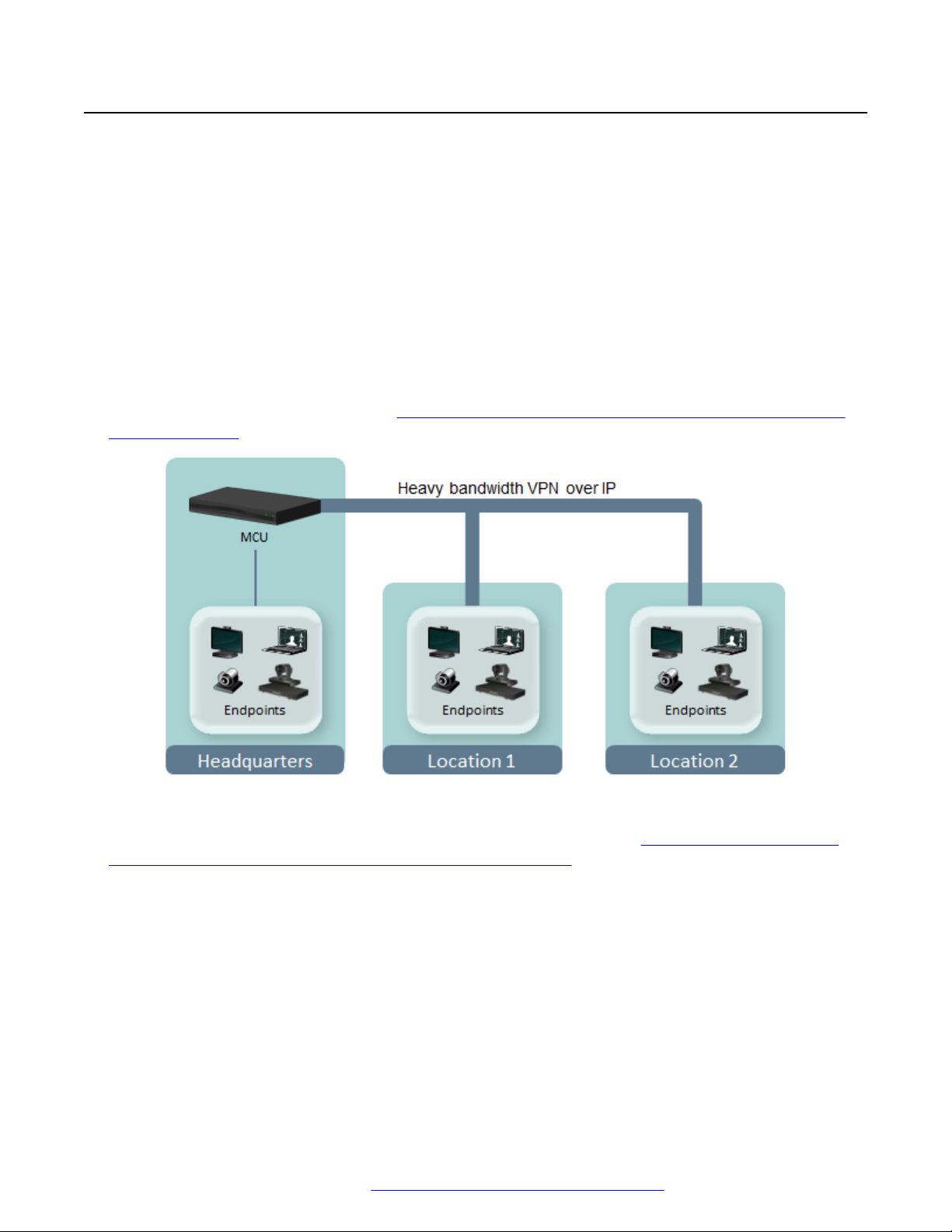
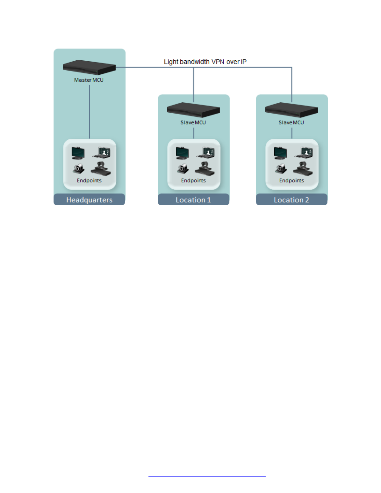
To reduce cross-site bandwidth costs, a distributed MCU deployment (Figure 3: Distributed MCU
deployment cascading meetings for reduced WAN bandwidth on page 17) can perform cascaded
conferences. Participants connect to their local MCU, and the conference is cascaded by connecting
between the MCUs using a fraction of the bandwidth compared to the centralized deployment. The
same principles apply to an MCU in the same location, thus increasing call capacity by cascading
conferences between them.
February 2016 Avaya Scopia® Elite 6000 Series MCU Installation Guide 16
Comments on this document? infodev@avaya.com
Planning a Centralized or Distributed Topology (Cascading) for MCU
Figure 3: Distributed MCU deployment cascading meetings for reduced WAN bandwidth
The bandwidth used by a cascaded link is equivalent to only a single client connection in each
direction: upload and download. The bandwidth value is determined by the MCU meeting type (or
service), which is invoked when choosing a dial prefix for the meeting. You define the maximum
bandwidth for each meeting type in the MCU. For more information on defining meeting types, see
Administrator Guide for Scopia® Elite 6000 Series MCU.
Users do not need to choose a specific MCU. The powerful functionality of virtual rooms enables
you to dial the same number anywhere in the world, while the Scopia® Solution infrastructure
transparently directs you to the correct meeting on the correct MCU.
The maximum supported number of participants in a single videoconference is 500 for both the
centralized and distributed MCU deployment.
Users do not need to manually enable cascading when creating meetings. This is performed
transparently by Avaya Scopia® Management using sophisticated cascading algorithms.
When an endpoint initiates a meeting on an MCU, that MCU becomes the master MCU. Other
MCUs which participate in the meeting are designated as slave MCUs. There are a number of
factors that might influence when the system automatically chooses to cascade to a different MCU.
For example, to avoid reaching the maximum bandwidth threshold, the system would attempt
cascading with a different MCU, a slave MCU. Endpoints would then join the videoconference from
the slave MCU. Only one level of cascading is supported: all slave MCU conferences must cascade
to the same master MCU conference. Administrators can also customize the priority given to
cascading in a distributed topology, as explained in Administrator Guide for Avaya Scopia
®
Management .
February 2016 Avaya Scopia® Elite 6000 Series MCU Installation Guide 17
Comments on this document? infodev@avaya.com

Planning your MCU Deployment
Cascading has the following characteristics:
• A cascaded connection uses two port s—one port on the master MCU, and one port on the
slave MCU.
• Make sure that the Meeting Type (MCU service), representing the required meeting properties
and accessed with a dial prefix, is available on all participating MCUs. For example, if the
meeting uses MCU service 81, then 81 must exist on the master MCU and on the slave MCUs.
• Participants connecting to the slave MCU:
- View only the default meeting layout
- Can send and receive video with a resolution up to 720p (for Scopia® Elite 5000 Series
MCU)
- Perform actions (such as joining the meeting) via their endpoint or web interface, and not via
DTMF.
• Only one participant at a time (typically the active speaker) connecting from each slave MCU
can send video and be seen by other meeting participants in the video layout.
• The lecturer and any telepresence endpoint always connect to the videoconference from the
master MCU. Port s are reserved on the master MCU to support these features.
• Endpoints seamlessly join a videoconference according to the cascading logic implemented on
the sites. An endpoint connected to a slave MCU and trying to launch a feature which is not
supported by the slave MCU gets a relevant error message. You can move an endpoint to a
master MCU when scheduling your videoconference. For more information, see User Guide for
Scopia® Management.
• Scopia® Elite MCU does not support cascading to a Scopia® MCU.
You can customize the cascading priorities in Scopia® Management in a number of ways:
• Default to using a local MCU first, and only cascade conferences if required.
• Prioritize cascading wherever possible, to keep bandwidth costs to an absolute minimum.
• Avoid cascading as often as possible.
For more information on implementing cascading in Scopia® Management, see Administrator Guide
for Avaya Scopia® Management .
Related links
Planning your MCU Deployment on page 15
Planning Network Redundancy or IP Separation (Dual NIC)
The device has two network cards (NICs) which can be used in one of the following ways:
• Use the second NIC as a redundant backup of the first, to provide a cost-effective,
uninterrupted service.
February 2016 Avaya Scopia® Elite 6000 Series MCU Installation Guide 18
Comments on this document? infodev@avaya.com
About the Capacity of the MCU
With network redundancy, the primary NIC is actively responsible for all management, media
and signaling traffic, while the secondary NIC is a backup. The NICs are paired, so they are
both connected to the same network switch, and the IP addresses you configure on one NIC
are automatically mirrored to the other NIC, as described in
Addresses on page 43.
When a failure is resolved, the MCU moves traffic back to the primary NIC and the secondary
NIC returns to its standby state.
You can increase MCU capacity by adding more devices to your existing deployment (see
Deploying Redundant MCUs on page 15).
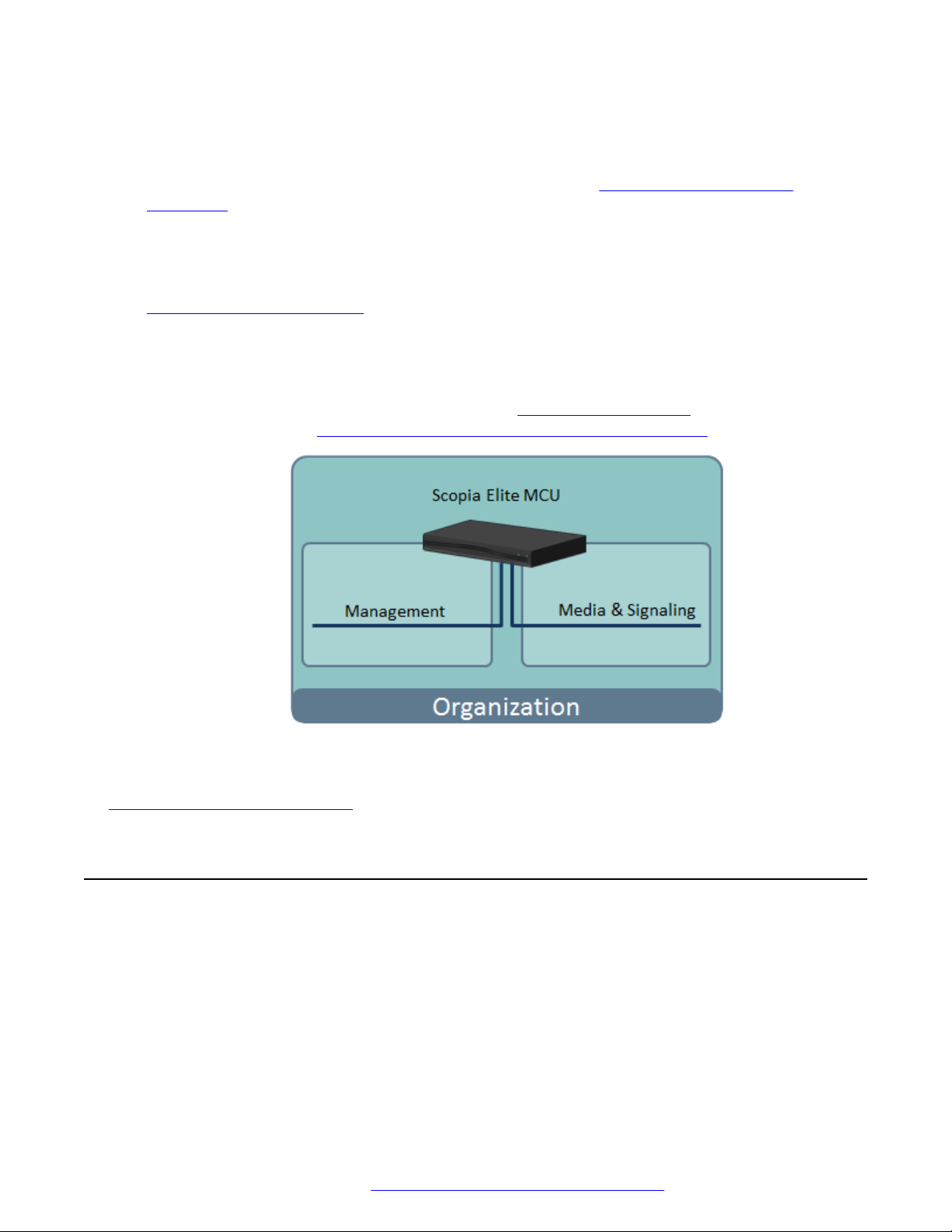
• Implement IP separation, to enhance security within the enterprise.
IP separation configures one NIC to handle management traffic (like administrator web access)
while the other controls media (video, audio and presentation) and signaling (call setup).
Connect each network port to a different subnet (
more information, see Configuring IP Separation (Dual NIC) on the Device on page 55.
Figure 4: IP separation on page 19). For
Configuring the Device IP
Figure 4: IP separation
Related links
Planning your MCU Deployment on page 15
About the Capacity of the MCU
The MCU's capacity is measured in terms of the maximum number of simultaneous connections to
a videoconference supported by this device.
The impact of a connection on the MCU's capacity depends on the bandwidth of the connection,
which in turn is dependent on the resolution and frame rate of that connection. Therefore the same
meeting can support a mix of HD and SD connections.
February 2016 Avaya Scopia® Elite 6000 Series MCU Installation Guide 19
Comments on this document? infodev@avaya.com
Planning your MCU Deployment
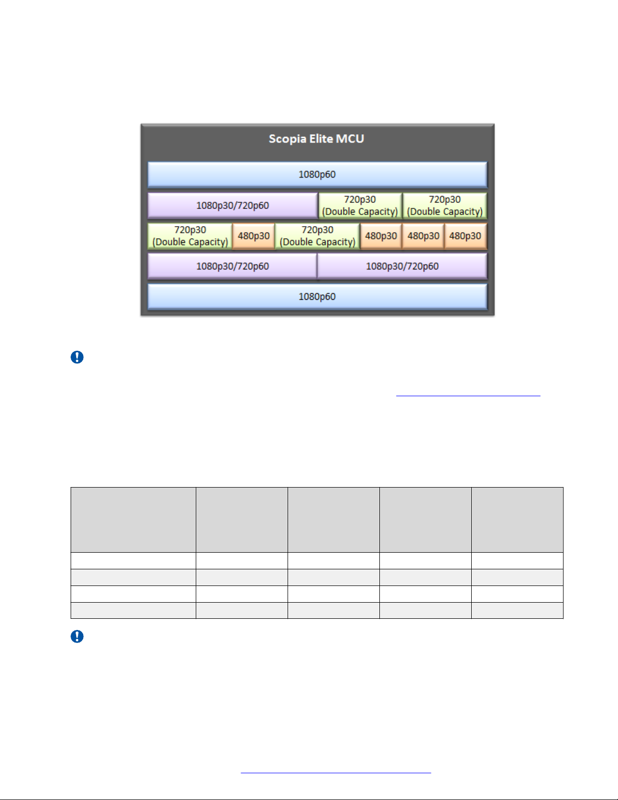
For example, a connection at 1080p at 30fps or 720p at 60fps uses half the capacity of a 1080p
connection at 60fps. Similarly, a connection at 480p at 30fps uses a quarter of the resources of a
1080p connection at 30fps, or one-eighth of the resources of a 1080p 60fps connection.
Figure 5: A connection uses its proportion of resources on the MCU
Important:
To enable connections at 720p at 30fps to use half the capacity of a 1080p 30fps connection,
install the Double Capacity license. For more information, see
Adding a License to the MCU on
page 50.
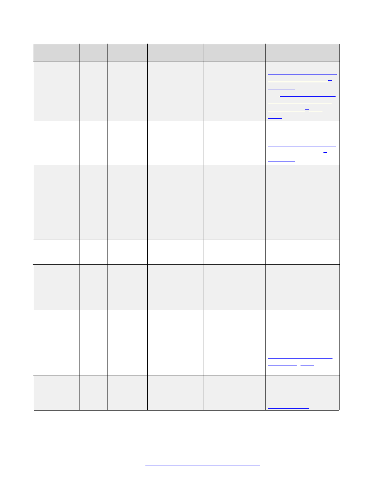
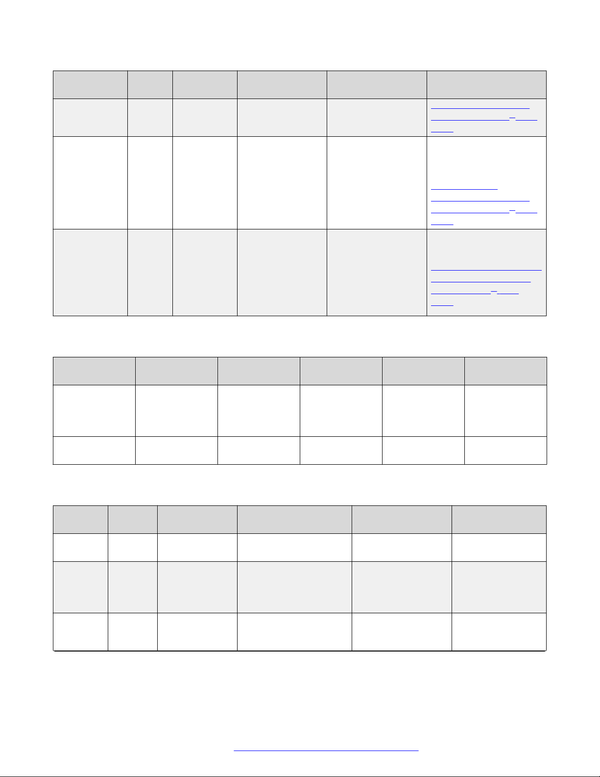
The following table details the number of simultaneous connections available for each of the devices
when all the connections have the same video resolution and frame rate.
Table 2: Number of simultaneous connections available at different video quality settings
Scopia® Elite 6000
Series MCU Model
Scopia® Elite MCU 6105 3 5 10 20
Scopia® Elite MCU 6110 5 10 20 40
Scopia® Elite MCU 6120 10 20 40 80
Scopia® Elite MCU 6140 20 40 80 160
1080p at 60fps 1080p at 30fps,
720p at 60fps,
720p at 30fps (no
double capacity
license)
720p at 30fps
(with double
capacity license)
480p at 30fps
Important:
You can increase the device's capacity at any resolution (including 1080p at 60fps) to the same
capacities listed under 480p by enabling Switched Video in the meeting type (or service).
Switching is the process of redirecting video as-is without transcoding, so you see only one
February 2016 Avaya Scopia® Elite 6000 Series MCU Installation Guide 20
Comments on this document? infodev@avaya.com

Ports to Open for the Scopia® Elite 6000 Series MCU
endpoint's image at a time, usually the active speaker, without any video layouts or continuous
presence (CP). For more information on enabling switching, see Administrator Guide for Scopia
Elite MCU.
However, if you encrypt the media and enable switching in the same MCU service, the
resolution may be dynamically lowered slightly in some cases, but overall MCU capacity
remains constant.
If you want to limit the resolution and frame rate of all connections to a meeting, define a meeting
type (MCU service) in the MCU and place the limit there. For more information, see Administrator
Guide for Scopia® Elite MCU. Alternatively, you can limit the bandwidth using the global bandwidth
policies in Scopia® Management.
Related links
Planning your MCU Deployment on page 15
Ports to Open for the Scopia® Elite 6000 Series MCU
The Scopia® Elite 6000 Series MCU is typically located in the enterprise network and is connected
to the DMZ. When opening ports on the Scopia® Elite MCU, use the following as a reference:
• If you are opening ports that are both in and out of the Scopia® Elite 6000 Series MCU, see
Table 3: Bidirectional Ports to Open on the Scopia® Elite 6000 Series MCU on page 21.
• If you are opening ports inbound to the Scopia® Elite 6000 Series MCU, see
Table 5: Inbound
Ports to Open to the Scopia® Elite 6000 Series MCU on page 23.
Important:
The specific firewalls you need to open ports on depends on where your MCU and other
Scopia® Solution products are deployed.
Table 3: Bidirectional Ports to Open on the Scopia® Elite 6000 Series MCU
Port Range ProtocolDestination Functionality Result of Blocking
Port
1024-1324 H.245
(TCP)
1719 RAS
(UDP)
Any H.323
device
H.323
gatekeeper
Enables H.245
signaling
Enables RAS
signaling
Cannot connect H.
323 calls
Cannot
communicate with H.
323 gatekeeper
Required
Mandatory
To configure, see
Configuring the TCP Port
Range for H.245 on the
Scopia® Elite MCU on
page 67
Mandatory
Table continues…
February 2016 Avaya Scopia® Elite 6000 Series MCU Installation Guide 21
Comments on this document? infodev@avaya.com
Planning your MCU Deployment
Port Range ProtocolDestination Functionality Result of Blocking
Port
1720 Q.931
(TCP)
3336 XML
(TCP)
Any H.323
device
Conference
Control web
client
endpoint,
Scopia
®
Enables Q.931
signaling
Enables you to
manage the MCU
via the XML API
Cannot connect H.
323 calls
Cannot use MCU
Conference Control
web user interface.
Cannot use XML
API to control MCU.
Managemen
t, or thirdparty
controlling
applications
3337 XML
(TCP)
Other MCUs Enables use of
MCU Cascading
Cannot cascade
between two MCUs
XML API
3338 XML
(TCP)
Scopia
Managemen
t, or thirdparty
®
Enables you to
configure the
MCU via the XML
Cannot configure
MCU via the XML
API
API
configuration
applications
3400-3580 SIP
BFCP
(TCP)
Any SIP
video
network
Enables SIP
content sharing
Cannot share SIP
contents
device
5060 SIP
(TCP/
UDP)
Any SIP
video
network
Enables SIP
signaling
Cannot connect SIP
calls
device
Required
To configure, see
Configuring the UDP Port
for RAS on the Scopia
®
Elite MCU on page 69
and Configuring the UDP
Port for the Gatekeeper
on the Scopia® Elite
MCU on page 70
Mandatory
To configure, see
Configuring the TCP Port
Q.931 on the Scopia
®
Elite MCU on page 70
Mandatory if deployed
with Scopia
®
Management
Mandatory if multiple
MCUs are deployed with
Scopia® Management
Mandatory if deployed
with Scopia
®
Management
Mandatory if using
content sharing with SIP
over TCP
To configure, see
Configuring the TCP Port
Range for SIP BFCP on
the Scopia® Elite
MCU on page 72
Mandatory if using SIP
over TCP/ UDP
To configure, see
Configuring the
Table continues…
February 2016 Avaya Scopia® Elite 6000 Series MCU Installation Guide 22
Comments on this document? infodev@avaya.com
Ports to Open for the Scopia® Elite 6000 Series MCU
Port Range ProtocolDestination Functionality Result of Blocking
Port
5061 SIP
(TLS)
Any SIP
video
Enables secure
SIP signaling
Cannot connect SIP
calls over TLS
network
device
12000-13200
16384-16984
RTP/
RTCP/
SRTP
(UDP)
Any H.323
or SIP
mediaenabled
Enables real-time
delivery of video
and audio media
Cannot transmit/
receive video media
streams
video
network
device
Table 4: Outbound ports to open from Scopia® Elite 6000 Series MCU
Required
TCP/UDP/TLS Port for
SIP on the Scopia® Elite
MCU on page 71
Mandatory if using SIP
over TLS
To configure, see
Configuring the
TCP/UDP/TLS Port for
SIP on the Scopia® Elite
MCU on page 71
Mandatory
To configure, see
Configuring the UDP Port
Ranges for RTP/RTCP
on the Scopia® Elite
MCU on page 66
Port range Protocol Destination Function Result of
blocking port
162 SNMP (UDP) Scopia
Management or
any SNMP
®
Enables sending
SNMP trap
Cannot send
SNMP traps
events
manager station
53 DNS (TCP/UDP) DNS server Enable querying
DNS is disabled Mandatory
DNS for FQDN
Table 5: Inbound Ports to Open to the Scopia® Elite 6000 Series MCU
Port
Range
21 FTP
22 SSH
Protocol Destination Functionality Result of Blocking
Port
(TCP)
(TCP)
FTP Server Enables audio stream
recording
SSH Client Enables you to view
logs
Cannot record audio
streams
Cannot view logs in
real-time (logs are
collected on the
compact flash card)
80 HTTP
(TCP)
Web client Provides access to the
MCU Administrator and
Cannot configure
MCU
Conference Control web
Required
Recommended
Required
Optional
Optional
Mandatory if using
HTTP
Table continues…
February 2016 Avaya Scopia® Elite 6000 Series MCU Installation Guide 23
Comments on this document? infodev@avaya.com

Planning your MCU Deployment
Port
Range
443 HTTPS
Protocol Destination Functionality Result of Blocking
Web client Provides secure access
(HTTP
over
SSL)
Related links
Planning your MCU Deployment on page 15
user interfaces; used for
software upgrade
to the MCU
Administrator and
Conference Control web
user interfaces; used for
software upgrade
Port
Cannot configure
MCU
Required
To configure, see
Configuring the
HTTP Port on the
Scopia® Elite
MCU on page 68
Mandatory if using
HTTPS
February 2016 Avaya Scopia® Elite 6000 Series MCU Installation Guide 24
Comments on this document? infodev@avaya.com

Chapter 3: Preparing the MCU Setup
Perform procedures in this section to prepare the site and device for installation.
Related links
Checking Site Suitability on page 25
Unpacking the Device on page 25
Inspecting for Damage on page 26
Checking Site Suitability
Prior to setting up your device, you need to verify your site suitability for:
• System power requirements
• System environmental requirements
• The device physical dimensions.
For more information, see Minimum Requirements and Specifications on page 12 to learn about
these requirements. Ensure the site conforms to the listed requirements.
Related links
Preparing the MCU Setup on page 25
Unpacking the Device
About this task
We strongly recommend that you follow safety guidelines described in this section during unpacking.
Procedure
1. Inspect the shipping box to verify that it is not seriously damaged during shipping.
2. Place the shipping box on a horizontal surface paying attention to the This Side Up symbol
on the shipping box (Figure 6: This Side Up symbol on page 26).
February 2016 Avaya Scopia® Elite 6000 Series MCU Installation Guide 25
Comments on this document? infodev@avaya.com

Preparing the MCU Setup
Caution:
The accessories kit is situated on top of the device inside the shipping box and can be
damaged if the box is placed upside down. Pay attention to the This Side Up symbol on
the shipping box to handle the box correctly at all times.
Caution:
To prevent injury and equipment damage, follow the lifting guidelines described in the
Safety Guide when lifting or moving the shipping box.
3. Cut the plastic straps.
Caution:
The plastic straps are tightly stretched and can hit you when you cut them. To avoid this,
make sure you do not face the side of the box secured by the straps before you cut the
straps.
Figure 6: This Side Up symbol
4. Cut the strapping tape.
5. Open the shipping box.
6. Take the accessories kit out of the shipping box.
7. Take the device out of the shipping box.
8. Carefully open the additional boxes, remove the packing material, and remove the drives
and other contents.
Important:
We recommend keeping the packaging materials in case you need to repack the device.
9. Remove the cellophane wrapping from the server case.
10. After opening the shipping box, check the shipment is complete. Compare the contents of
the shipment with the packing list included in the box.
Related links
Preparing the MCU Setup on page 25
Inspecting for Damage
After you verify that all of the equipment is included, carefully examine the cards, power supplies
and cables for any damage resulting from shipping. If you suspect any damage from shipping,
February 2016 Avaya Scopia® Elite 6000 Series MCU Installation Guide 26
Comments on this document? infodev@avaya.com

Inspecting for Damage
contact your local freight carrier for procedures on damage claims. If you observe any physical
defects in the items you ordered, contact Technical Support for Return Material Authorization (RMA)
form.
Important:
Before proceeding with the installation, verify that all of the ordered parts are present and in
good condition. Keep a record of the parts and serial numbers. If any parts are missing or
damaged, contact your sales representative.
Related links
Preparing the MCU Setup on page 25
February 2016 Avaya Scopia® Elite 6000 Series MCU Installation Guide 27
Comments on this document? infodev@avaya.com

Chapter 4: Setting up the Device
These sections describe how to set up the device:
Related links
Adding a Power Supply Unit to the MCU on page 28
Mounting the Device on to the Rack on page 30
Connecting Cables to the Device on page 41
Configuring the Device IP Addresses on page 43
Adding a Power Supply Unit to the MCU
About this task
This section details how to set up an additional power supply unit (PSU) of the Scopia® Elite MCU,
which can house two PSUs.
Important:
This applies to the 6140 model only. For details of replacing a PSU of the Scopia® Elite 5200
Series MCU, see the Administrator Guide of Scopia® Elite 5200 Series MCU version 7.7.
If one of the PSUs fails, the remaining PSU takes the full load of the system to enable continued
operation without interruption. PSUs can be hot-swapped, enabling you to replace the power unit
without powering down the device.
You can add the PSU when the MCU is functioning. However, Avaya strongly recommends to turn
off the MCU when you perform the procedure for the first time.
To remove an existing PSU from the device, see Administrator Guide for Scopia® Elite MCU.
Before you begin
Verify you have the following equipment:
• The standalone PSU that you can order from your local Avaya representative using these
references:
- Scopia® Elite MCU Redundant Power Supply
- Part number 55547-00018
• An antistatic wrist strap
February 2016 Avaya Scopia® Elite 6000 Series MCU Installation Guide 28
Comments on this document? infodev@avaya.com
 Loading...