

Avaya S8800 User Manual

Installing the Avaya S8800 Server for
Avaya Aura
™
Communication Manager
Release 6.0
03-603444
June 2010

©
2010 Avaya Inc.
All Rights Reserved.
Notices
While reasonable efforts have been made to ensure that the
information in this document is complete and accurate at the time of
printing, Avaya assumes no liability for any errors. Avaya reserves the
right to make changes and corrections to the information in this
document without the obligation to notify any person or organization of
such changes.
For full support, please see the complete document, Avaya Support
Notices for Hardware Documentation, document number 03–600759.
To locate this document on our Web site, simply go to
www.avaya.com/support and search for the document number in the
search box.
Documentation disclaimer
Avaya shall not be responsible for any modifications, additions, or
deletions to the original published version of this documentation unless
such modifications, additions, or deletions were performed by Avaya.
End User agree to indemnify and hold harmless Avaya, Avaya's agents,
servants and employees against all claims, lawsuits, demands and
judgments arising out of, or in connection with, subsequent
modifications, additions or deletions to this documentation, to the
extent made by End User.
Link disclaimer
Avaya is not responsible for the contents or reliability of any linked Web
sites referenced within this site or documentation(s) provided by Avaya.
Avaya is not responsible for the accuracy of any information, statement
or content provided on these sites and does not necessarily endorse
the products, services, or information described or offered within them.
Avaya does not guarantee that these links will work all the time and has
no control over the availability of the linked pages.
Warranty
Avaya provides a limited warranty on this product. Refer to your sales
agreement to establish the terms of the limited warranty. In addition,
Avaya’s standard warranty language, as well as information regarding
support for this product, while under warranty, is available to Avaya
customers and other parties through the Avaya Support Web site:
http://www.avaya.com/support. Please note that if you acquired the
product from an authorized Avaya reseller outside of the United States
and Canada, the warranty is provided to you by said Avaya reseller and
not by Avaya.
Copyright
Except where expressly stated otherwise, no use should be made of
materials on this site, the Documentation(s) and Product(s) provided
by Avaya. All content on this site, the documentation(s) and the
product(s) provided by Avaya including the selection, arrangement and
design of the content is owned either by Avaya or its licensors and is
protected by copyright and other intellectual property laws including the
sui generis rights relating to the protection of databases. You may not
modify, copy, reproduce, republish, upload, post, transmit or distribute
in any way any content, in whole or in part, including any code and
software. Unauthorized reproduction, transmission, dissemination,
storage, and or use without the express written consent of Avaya can
be a criminal, as well as a civil, offense under the applicable law.
Contact Avaya Support
Avaya provides a telephone number for you to use to report problems
or to ask questions about your product. The support telephone number
is 1-800-242-2121 in the United States. For additional support
telephone numbers, see the Avaya Web site:
support
http://www.avaya.com/
http://
2 Installing the Avaya S8800 Server for Avaya Aura™ Communication Manager June 2010

Contents
Chapter 1: Overview of server and components....................................................................5
Introduction.......................................................................................................................................................5
Front of server...................................................................................................................................................5
Back of server...................................................................................................................................................7
Server specifications.........................................................................................................................................8
Server components...........................................................................................................................................9
Environmental requirements...........................................................................................................................12
Chapter 2: Server rack installation........................................................................................13
Safety instructions...........................................................................................................................................13
Avaya-provided equipment..............................................................................................................................14
Customer-provided equipment........................................................................................................................14
Clearance requirements..................................................................................................................................15
Server installation checklist.............................................................................................................................15
Installing the Avaya S8800 Server..................................................................................................................16
Rack installation components.................................................................................................................16
Attaching the rails to the rack.................................................................................................................17
Installing the server in the rack...............................................................................................................19
Installing the cable management arm.....................................................................................................21
Turning on the server......................................................................................................................................24
Chapter 3: Installing and connecting peripheral equipment...............................................27
Installing peripheral equipment.......................................................................................................................27
Overview.................................................................................................................................................27
Installing UPS.........................................................................................................................................27
Installing the Ethernet switch..................................................................................................................28
S8800 Ethernet port assignments..........................................................................................................28
SAL gateway installation........................................................................................................................30
Connectivity.....................................................................................................................................................30
Connecting Ethernet cables...................................................................................................................30
Connecting the USB card reader............................................................................................................31
Connecting laptop for initial administration.............................................................................................32
Connecting to customer network............................................................................................................32
Connecting to port networks...................................................................................................................32
Connecting the cables for software memory duplication........................................................................33
Connecting for duplication reliability using software memory duplication...............................................35
Chapter 4: Troubleshooting equipment................................................................................37
Troubleshooting the hardware installation.......................................................................................................37
Avaya and customer equipment is missing............................................................................................37
The server has no power........................................................................................................................37
Index.........................................................................................................................................39
Installing the Avaya S8800 Server for Avaya Aura™ Communication Manager June 2010 3

4 Installing the Avaya S8800 Server for Avaya Aura™ Communication Manager June 2010
Chapter 1: Overview of server and
components
Introduction
The Avaya S8800 Server supports several Avaya software applications. The server is available
in a 1U model or 2U model and with various hardware components. The server model and
specific hardware components in your server depend on the requirements of the software
application that will run on the server.
Communication Manager supports the 1U model of the S8800 Server. While installing
Communication Manager in simplex mode on the S8800 Server, you only use 1 S8800 Server,
whereas, installing Communication Manager in duplex mode requires you to have 2 S8800
Servers.
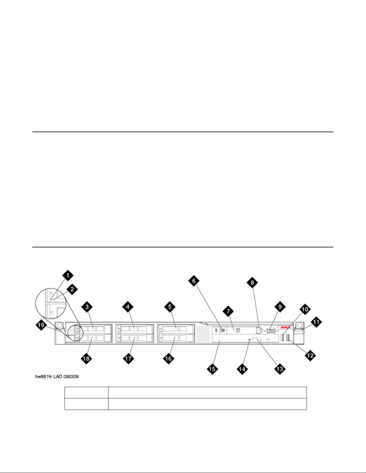
Front of server
1
2 Hard disk drive status LED (amber)
Hard disk drive activity LED (green)
Installing the Avaya S8800 Server for Avaya Aura™ Communication Manager June 2010 5
Overview of server and components
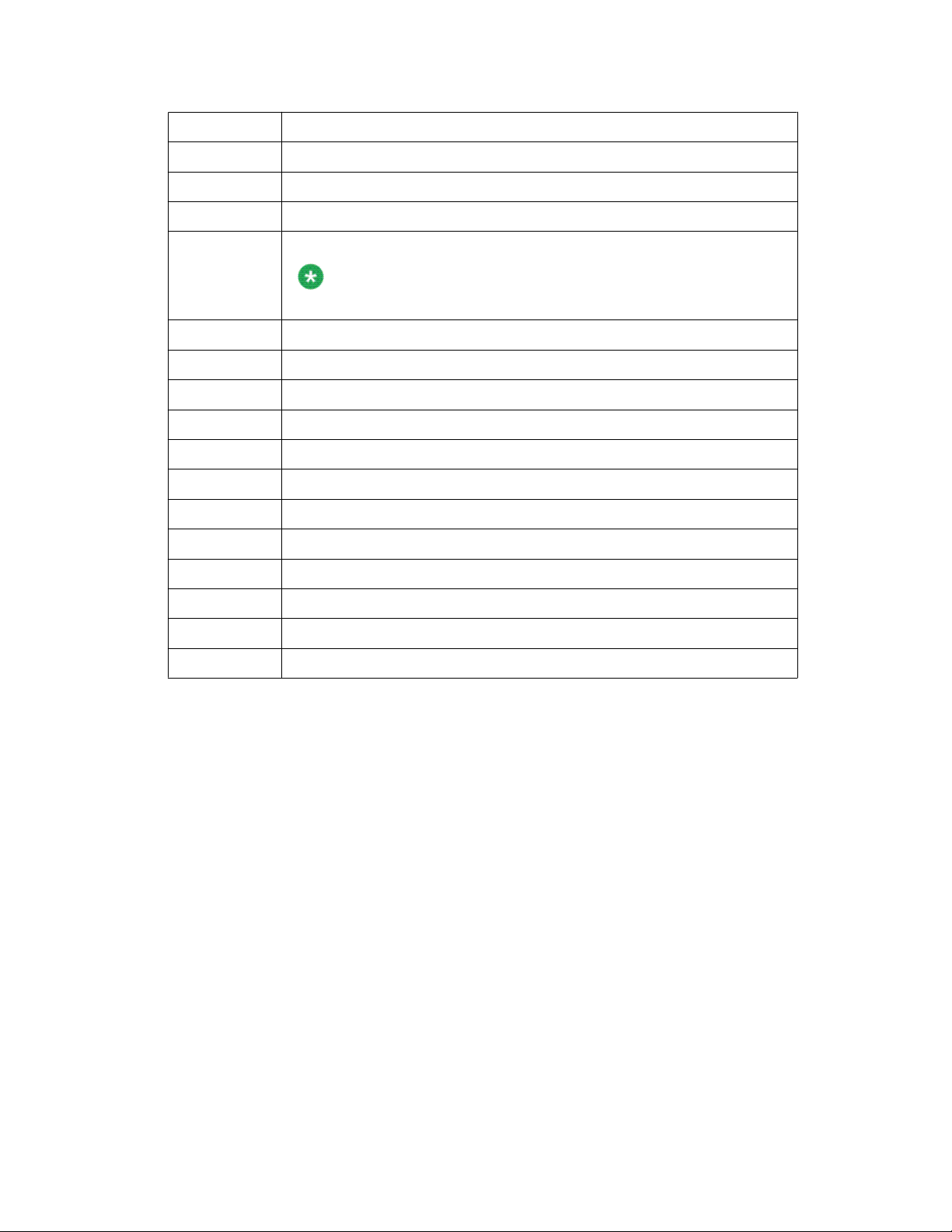
3 Drive bay 0
4 Drive bay 2 (unused for Communication Manager)
5 Drive bay 4 (unused for Communication Manager)
6 Power control button and LED
7 Operator information panel
The operator information panel is shown in the pushed in position.
8 Operator information panel release latch
9 Video connector
10 USB connector 1
11 Rack release latch
12 USB connector 2
13 DVD eject button
14 DVD drive activity LED
Note:
15 DVD drive
16 Drive bay 5 (Unused for Communication Manager)
17 Drive bay 3 (Unused for Communication Manager)
18 Drive bay 1
19 Rack release latch
6 Installing the Avaya S8800 Server for Avaya Aura™ Communication Manager June 2010
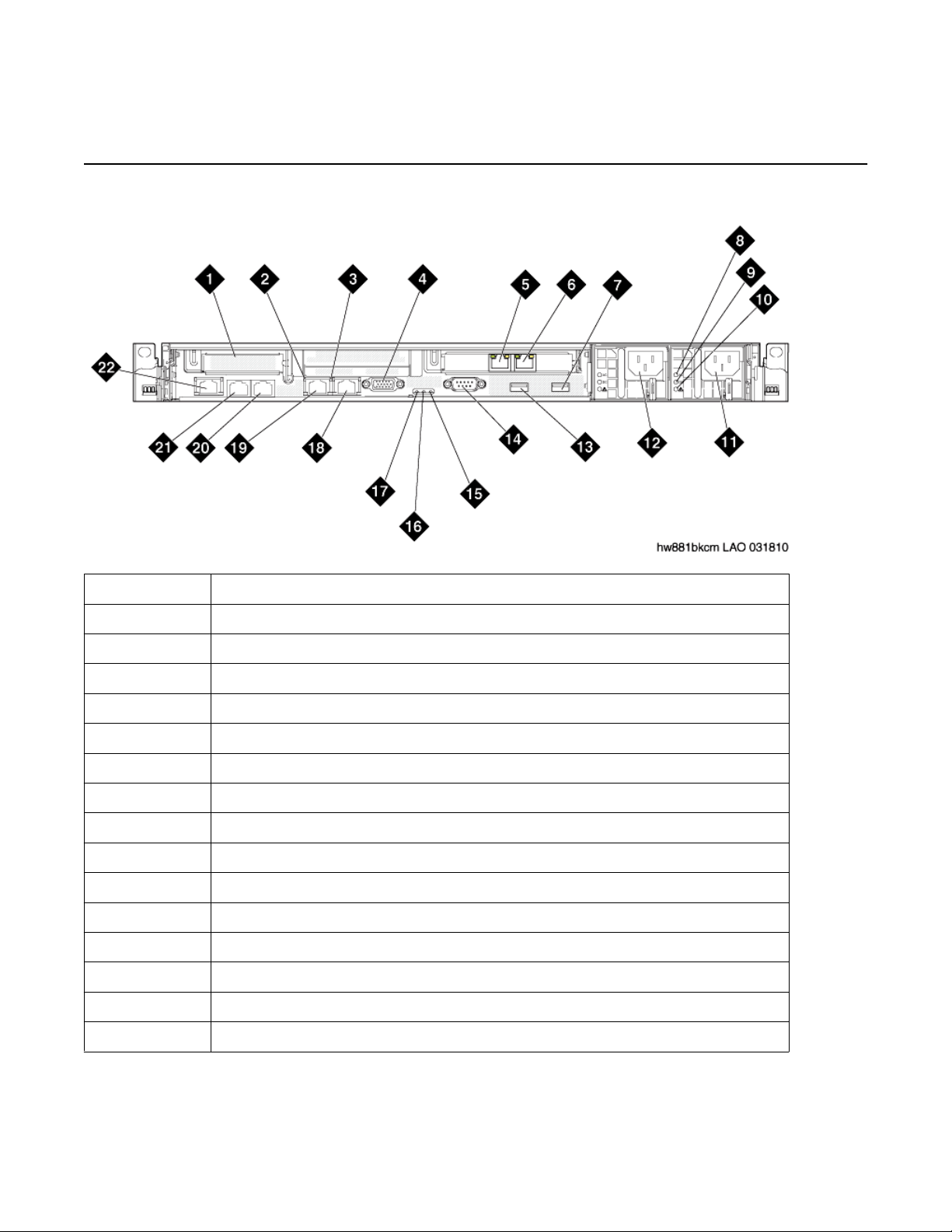
Back of server
Back of server
1 PCIe slot 1 (unused)
2 Ethernet activity LED
3 Ethernet link LED
4 Video connector
5 Ethernet connector 6 (eth5) (unused)
6 Ethernet connector 5 (eth4) (second NIC for bonding to eth0 for redundancy)
7 USB connector 4
8 AC power LED (green)
9 DC power LED (green)
10 Power supply error LED (amber)
11 Power supply 2 (optional redundant power supply)
12 Power supply 1 (primary power supply)
13 USB connector 3
14 Serial connector
15 System error LED (amber)
16 System locator LED (blue)
Installing the Avaya S8800 Server for Avaya Aura™ Communication Manager June 2010 7
Overview of server and components
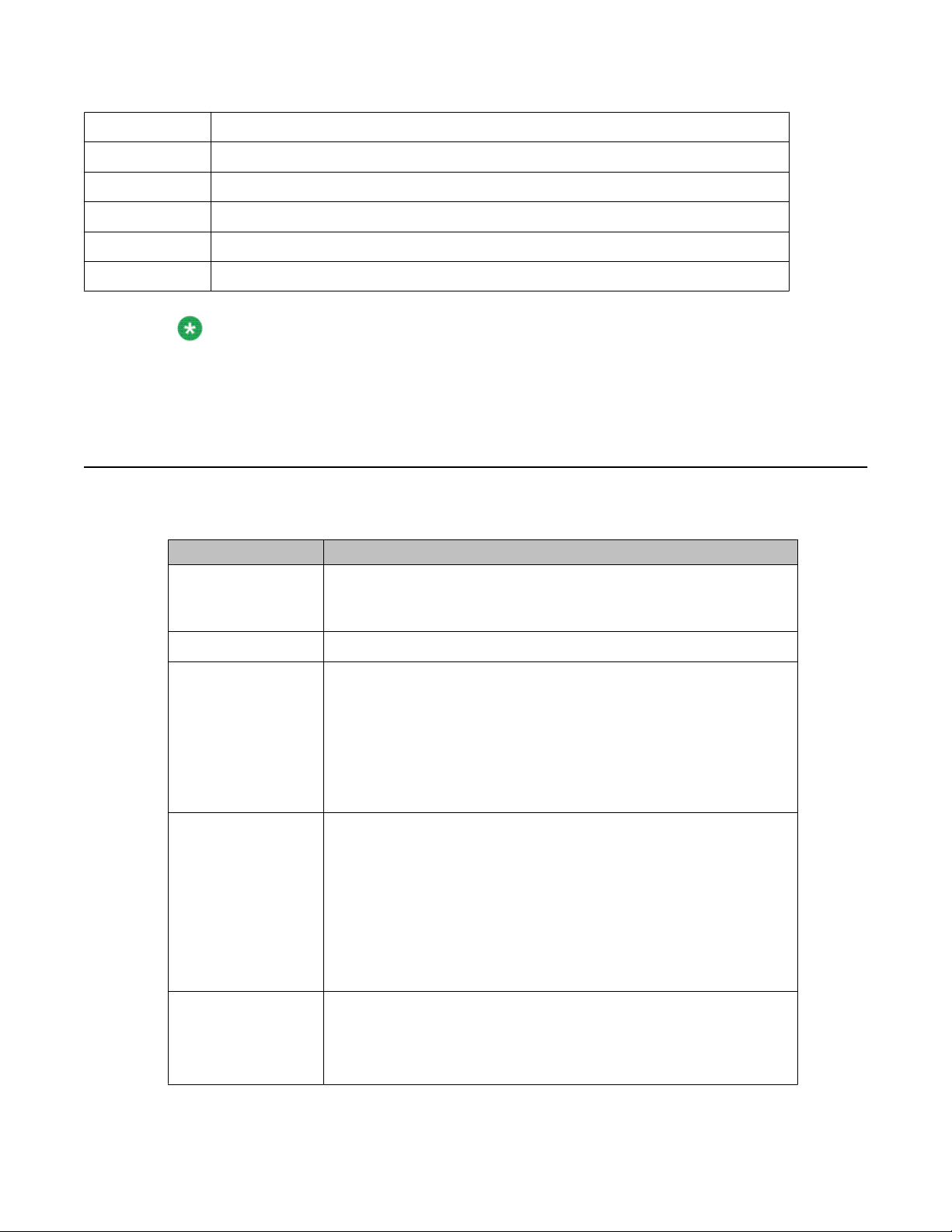
17 Power LED (green)
18 Ethernet connector 2 (eth 1) (services port)
19 Ethernet connector 1 (eth 0) (Corporate LAN / processor Ethernet)
20 Ethernet connectors 4 (eth 3) (Duplication link if configuration is duplicated server)
21 Ethernet connectors 3 (eth 2) (not used)
22 System management Ethernet connector (IMM)
Note:
Hardware label for Ethernet ports on the server is called Ethernet connectors.
Communication Manager software refers to Ethernet ports as eth.
Server specifications
Type Description
Dimensions Height: 43 mm (1.69 inches, 1U)
Depth: 711 mm (28 inches)
Width: 440 mm (17.3 inches)
Weight Maximum weight: 15.4 kg (34 lb.) when fully configured.
Heat output Approximate heat output:
• Minimum configuration: 662 Btu per hour (194 watts)
• Maximum configuration: 1400 Btu per hour (400 watts)
Heat output varies depending on the number and type of optional
features that are installed and the power-management optional
features that are in use.
Acoustic noise
emissions
Declared sound power, operating: 6.1 bel
The sound levels were measured in controlled acoustical
environments according to the procedures specified by the American
National Standards Institute (ANSI) S12.10 and ISO 7779 and are
reported in accordance with ISO 9296. Actual sound-pressure levels
in a given location might exceed the average values stated because
of room reflections and other nearby noise sources. The declared
sound-power levels indicate an upper limit, below which a large
number of computers will operate.
Electrical input
requirements
8 Installing the Avaya S8800 Server for Avaya Aura™ Communication Manager June 2010
• Sine-wave input (47 - 63 Hz) required
• Input voltage low range:
- Minimum: 100 V AC
Type Description
- Maximum: 127 V AC
• Input voltage high range:
- Minimum: 200 V AC
- Maximum: 240 V AC
• Input kilovolt-amperes (kVA), approximately:
- Minimum: 0.194 kVA
- Maximum: 0.700 kVA
Server components
Front connectors
Back connectors
Server components
Component Minimum specification Upgrade options
Microprocessor One Intel E5520 quad
• Two USB
• Video
• Six Ethernet (RJ— 45 connectors).
• Serial
• Two USB
• Video
• Systems management Ethernet (IMM)
based on product
requirements
No additional options
core, 2.26 GHZ processor
Memory S8510 Server — 8 GB of
DRAM (Install an
additional 1 GB DRAM
DIMMS to achieve 8GB of
DRAM)
S8800 Server — 12GB
DRAM
S8330D — 8GB DRAM
Media drive DVD-R/W SATA slimline No additional options
Hard disk drive expansion bays Six 2.5-inch hot-swap
SAS hard disk drive bays
Installing the Avaya S8800 Server for Avaya Aura™ Communication Manager June 2010 9
No additional options
No additional options
Overview of server and components
Component Minimum specification Upgrade options
based on product
requirements
Hard disk drive S8510 Server – 2 drives
each 3.5” 250GB SATA
drives configured as a
RAID 1 array yielding 232
GB of usable disk space
or 3 drives each 2.5” 146
GA SAS drives
configured as a RAID 5
array yielding 272 GB of
usable disk space
S8800 Server — 3 each
2.5” 146 GB SAS hard
drives configured in a
RAID 5 array yielding 272
GB of usable disk space
Note:
For an upgrade from
Communication
Manager R 5.2.1 on an
S8800 server to
Communication
Manager R 6.0 on an
S8800 Server, you
need to install four
additional 2 GB DRAM
DIMMS. Thus there is
a total of 12 GB of
DRAM installed in the
server. When installing
additional DRAM, the
DIMMs are to be
installed in accordance
with the instructions
found in the “Sequence
for populating DIMM
connectors” section on
page 20 of the
Maintaining the Avaya
S8800 Server for
Avaya Aura
™
Communication
Manager, doc #
03-603446, Issue 1,
November 2009.
S8300D Server — Single
250GB drive
No additional options
RAID controllers ServeRAID-MR10i RAID
No additional options
SAS adapter that
provides RAID level 1 or
5. Includes 256 MB cache
10 Installing the Avaya S8800 Server for Avaya Aura™ Communication Manager June 2010
Server components
Component Minimum specification Upgrade options
based on product
requirements
module and battery for
write cache
PCI expansion slots Two PCI Express x16
Gen 2 slots:
• Slot 1 supports a low
profile DUAL NIC card
(half height, half-length
cards)
• Slot 2 supports full
height, half-length
cards
Hot-swap fans Six No additional options
Power supply One 675W, 12V AC
power supply
Note:
The second
(redundant) power
supply is required if
you desire to have the
Communication
Manager system meet
or exceed an
availability
requirement of
99.99%.
No additional options
Redundant 675W, 12V
AC power supply
Video controller Integrated Matrox G200
(two analog ports, one
front and one back, that
can be connected at the
same time)
The maximum video
resolution is 1280 x 1024
at 75 Hz.
• SVGA compatible video
controller
• DDR2 250 MHz
SDRAM video memory
controller
• Avocent Digital Video
Compression
• Video memory is not
expandable
No additional options
Installing the Avaya S8800 Server for Avaya Aura™ Communication Manager June 2010 11
Overview of server and components
Component Minimum specification Upgrade options
Note:
You must remove the SAMP board (only applicable for an S8510 Server) before installing
Communication Manager R6.0 on the server.
Environmental requirements
Server status Air temperature Maximum Altitude Relative humidity
based on product
requirements
NA
Server on 10 to 35º C (50 to 95º F)
at altitude of up to 914.4
m (3,000 feet)
10 to 32º C (50 to 90º F)
at altitude of 914.4 m to
2,133 m (3,000 to 7,000
feet)
Server off 10°C to 43°C (50.0°F to
109.4°F)
2,133 m
(7,000 feet)
2,133 m
(7,000 feet)
8% to 80%
8% to 80%
12 Installing the Avaya S8800 Server for Avaya Aura™ Communication Manager June 2010
 Loading...