

Page 1

Installing the Avaya S8730 Server for
Modular Messaging
January 2009
Issue 1
Page 2

©
2009 Avaya Inc.
All Rights Reserved.
Notice
While reasonable efforts were made to ensure that the information in
this document was complete and accurate at the time of printing, Avaya
Inc. can assume no liability for any errors. Changes and corrections to
the information in this document might be incorporated in future
releases.
Documentation disclaimer
Avaya Inc. is not responsible for any modifications, additions, or
deletions to the original published version of this documentation unless
such modifications, additions, or deletions were performed by Avaya.
Customer and/or End User agree to indemnify and hold harmless
Avaya, Avaya's agents, servants and employees against all claims,
lawsuits, demands and judgments arising out of, or in connection with,
subsequent modifications, additions or deletions to this documentation
to the extent made by the Customer or End User.
Link disclaimer
Avaya Inc. is not responsible for the contents or reliability of any linked
Web sites referenced elsewhere within this documentation, and Avaya
does not necessarily endorse the products, services, or information
described or offered within them. We cannot guarantee that these links
will work all the time and we have no control over the availability of the
linked pages.
Warranty
Avaya Inc. provides a limited warranty on this product. Refer to your
sales agreement to establish the terms of the limited warranty. In
addition, Avaya’s standard warranty language, as well as information
regarding support for this product, while under warranty, is available
through the Avaya Support Web site:
Licenses
USE OR INSTALLATION OF THE PRODUCT INDICATES THE END
USER'S ACCEPTANCE OF THE TERMS SET FORTH HEREIN AND
THE GENERAL LICENSE TERMS AVAILABLE ON THE AVAYA WEB
http://support.avaya.com/LicenseInfo/ ("GENERAL LICENSE
SITE
TERMS"). IF YOU DO NOT WISH TO BE BOUND BY THESE TERMS,
YOU MUST RETURN THE PRODUCT(S) TO THE POINT OF
PURCHASE WITHIN TEN (10) DAYS OF DELIVERY FOR A REFUND
OR CREDIT.
Avaya grants End User a license within the scope of the license types
described below. The applicable number of licenses and units of
capacity for which the license is granted will be one (1), unless a
different number of licenses or units of capacity is specified in the
Documentation or other materials available to End User. "Designated
Processor" means a single stand-alone computing device. "Server"
means a Designated Processor that hosts a software application to be
accessed by multiple users. "Software" means the computer programs
in object code, originally licensed by Avaya and ultimately utilized by
End User, whether as stand-alone Products or pre-installed on
Hardware. "Hardware" means the standard hardware Products,
originally sold by Avaya and ultimately utilized by End User.
License type(s)
Designated System(s) License (DS). End User may install and use
each copy of the Software on only one Designated Processor, unless
a different number of Designated Processors is indicated in the
Documentation or other materials available to End User. Avaya may
require the Designated Processor(s) to be identified by type, serial
number, feature key, location or other specific designation, or to be
provided by End User to Avaya through electronic means established
by Avaya specifically for this purpose.
Concurrent User License (CU). End User may install and use the
Software on multiple Designated Processors or one or more Servers,
so long as only the licensed number of Units are accessing and using
the Software at any given time. A "Unit" means the unit on which Avaya,
at its sole discretion, bases the pricing of its licenses and can be,
http://www.avaya.com/support
limitation, an agent, port or user, an e-mail or voice mail account
without
in the name of a person or corporate function (e.g., webmaster or
helpdesk), or a directory entry in the administrative database utilized
by the Product that permits one user to interface with the Software.
Units may be linked to a specific, identified Server.
Named User License (NU). Customer may: (i) install and use the
Software on a single Designated Processor or Server per authorized
Named User (defined below); or (ii) install and use the Software on a
Server so long as only authorized Named Users access and use the
Software. "Named User," means a user or device that has been
expressly authorized by Avaya to access and use the Software. At
Avaya's sole discretion, a "Named User" may be, without limitation,
designated by name, corporate function (e.g., webmaster or helpdesk),
an e-mail or voice mail account in the name of a person or corporate
function, or a directory entry in the administrative database utilized by
the Product that permits one user to interface with the Product.
Shrinkwrap License (SR). With respect to Software that contains
elements provided by third party suppliers, End User may install and
use the Software in accordance with the terms and conditions of the
applicable license agreements, such as "shrinkwrap" or "clickwrap"
license accompanying or applicable to the Software ("Shrinkwrap
License"). The text of the Shrinkwrap License will be available from
Avaya upon End User’s request (see “Third-party Components" for
more information).
Copyright
Except where expressly stated otherwise, the Product is protected by
copyright and other laws respecting proprietary rights. Unauthorized
reproduction, transfer, and or use can be a criminal, as well as a civil,
offense under the applicable law.
Third-party components
Certain software programs or portions thereof included in the Product
may contain software distributed under third party agreements ("Third
Party Components"), which may contain terms that expand or limit
rights to use certain portions of the Product ("Third Party Terms").
Information identifying Third Party Components and the Third Party
Terms that apply to them is available on the Avaya Support Web site:
http://support.avaya.com/ThirdPartyLicense/
Preventing toll fraud
"Toll fraud" is the unauthorized use of your telecommunications system
by an unauthorized party (for example, a person who is not a corporate
employee, agent, subcontractor, or is not working on your company's
behalf). Be aware that there can be a risk of toll fraud associated with
your system and that, if toll fraud occurs, it can result in substantial
additional charges for your telecommunications services.
Avaya fraud intervention
If you suspect that you are being victimized by toll fraud and you need
technical assistance or support, call Technical Service Center Toll
Fraud Intervention Hotline at +1-800-643-2353 for the United States
and Canada. For additional support telephone numbers, see the Avaya
Support Web site:
Suspected security vulnerabilities with Avaya Products should be
reported to Avaya by sending mail to: [email protected].
Trademarks
All other trademarks are the property of their respective owners.
Downloading documents
For the most current versions of documentation, see the Avaya Support
Web site:
Contact Avaya Support
Avaya Inc. provides a telephone number for you to use to report
problems or to ask questions about your product. The support
telephone number is 1-800-242-2121 in the United States. For
additional support telephone numbers, see the Avaya Web site:
www.avaya.com/support
http://www.avaya.com/support
http://support.avaya.com
http://
2 Installing the Avaya S8730 Server for Modular Messaging January 2009
Page 3

Contents
Chapter 1: Overview of server and components....................................................................5
Overview..........................................................................................................................................................5
Server components..........................................................................................................................................5
MAS port boards..............................................................................................................................................7
Specifications....................................................................................................................................................8
Environmental specifications............................................................................................................................8
Front view of server..........................................................................................................................................9
Back view of server........................................................................................................................................10
Related hardware............................................................................................................................................10
LEDs................................................................................................................................................................11
Front panel LEDs....................................................................................................................................12
Back panel LEDs....................................................................................................................................14
Systems Insight Display LEDs................................................................................................................15
Chapter 2: Server installation................................................................................................17
Customer-provided equipment and access....................................................................................................17
Avaya-provided equipment..............................................................................................................................18
Recommended tools and supplies..................................................................................................................18
Recommended test equipment......................................................................................................................19
Safety instructions..........................................................................................................................................19
Installation checklist........................................................................................................................................20
Marking the rack..............................................................................................................................................22
Attaching rails to the server............................................................................................................................23
Attaching the rails to the rack..........................................................................................................................24
Installing the server in the rack......................................................................................................................25
Corporate and private LAN connections........................................................................................................26
Connecting the MAS to the Corporate LAN............................................................................................26
Connecting the MAS and MSS with a crossover cable..........................................................................27
Connecting the MAS and MSS with an Ethernet switch........................................................................28
Connecting MAS port boards..........................................................................................................................29
Connecting Dialogic port boards............................................................................................................29
Supported port board connections........................................................................................................29
Port board connections..........................................................................................................................30
Connecting power..........................................................................................................................................30
Troubleshooting the installation......................................................................................................................31
Avaya and customer equipment is missing............................................................................................31
The server has no power or a power fault..............................................................................................32
Index.........................................................................................................................................35
Installing the Avaya S8730 Server for Modular Messaging January 2009 3
Page 4

Contents
4 Installing the Avaya S8730 Server for Modular Messaging January 2009
Page 5
Chapter 1: Overview of server and
components
Overview
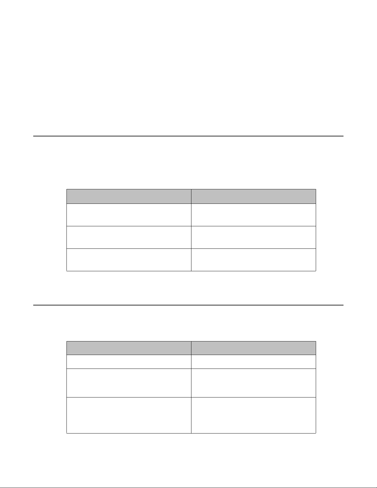
The Avaya S8730 server is available in several configurations to accommodate the
requirements of the software application or system it supports. Boxes are labeled to identify
the type of server.
Application Model Number
Modular Messaging Message
Application Server (MAS)
Modular Messaging Message Storage
Server — Standard Reliability (MSS-S)
Modular Messaging Message Storage
Server — High Reliability (MSS-H)
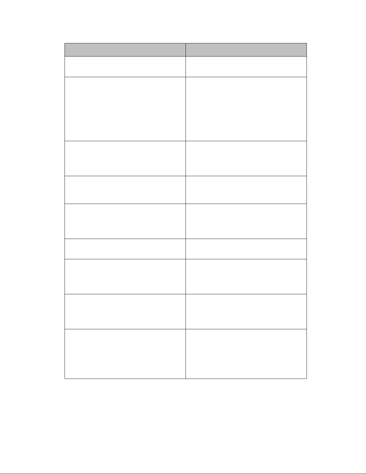
Server components
The server has the following components.
Component
Processor 1 Barcelona quad core processor
Memory 4 GB fully buffered PC2–5300 DIMMs
Model 03
Model 04
Model 05
Description
(2x2 GB) with advanced ECC
capabilities
Media Drive Model 03 — Slimline 8X/24X DVD-
ROM/CD-RW
Models 04 and 05 — Slimline 8X DVDRAM/RW
Installing the Avaya S8730 Server for Modular Messaging January 2009 5
Page 6
Overview of server and components
Component Description
RAID Configuration Models 03 and 04 — RAID 1
RAID Card Models 03 — Smart Array P400/256 MB
Hard disk drives Models 03 and 04 — Two 146 GB 10k
Network Interface Cards (NIC) Two integrated gigabit Ethernet NICs
Model 05 — RAID 5
DDR-2 RAM controller with battery
backed write cache
Model 04 — Smart Array E200/64 MB
DDR-1 RAM controller
Model 05 — Smart Array P400/256 MB
DDR-2 RAM controller with battery
backed write cache
2.5 inch SAS hot-plug hard drives
Model 05 — Four 72 GB 15k 2.5 inch
SAS hot-plug hard drives
capable of supporting 10-Mbps, 100Mbps, and 1000-Mbps data rates.
PCI card cage Models 03 and 04 — Three PCI Express
(PCI-e)
Model 05 — Two PCI Extended (PCIx) and one PCI Express (PCI-e)
Video controller Integrated ATI ES 1000 Graphics
Processing Unit (GPU)
Power supply 800 Watt, CE Mark Compliant hot-plug
power supply
Model 05 has an additional hot-plug
redundant power supply
Fans Six fully redundant hot-plug fans. The
fan configuration operates in redundant
mode only when all six fans are
installed.
System battery The server has an internal lithium
manganese dioxide, a vanadium
pentoxide, or an alkaline battery pack
that provides power to the real-time
clock. Under normal use, battery life is
5 to 10 years.
The server has the following connectors:
• USB — Four USB connectors: two front, two rear.
• NIC — Two NIC connectors used for private and corporate LAN connection on rear
panel.
6 Installing the Avaya S8730 Server for Modular Messaging January 2009
Page 7

• iLO 2 — One Integrated Lights-Out 2 (iLO 2) connector on rear panel (not used).
• Video connector — Two video connectors: one on front panel, one on rear panel.
• Serial, mouse and keyboard connectors on rear panel.
MAS port boards
Dialogic port boards are pre-installed in any new MAS (model 03) server that uses an analog,
Digital Set Emulation (DSE), E1–QSIG, or T1–QSIG switch integration protocol. Each server
can have only one type of board installed. The server supports only PCI Express (PCI-e)
Dialogic cards. Dialogic cards used in the S3400 and S3500 servers do not use the PCI-e form
factor and cannot be transferred to the S8730 server. The S8730 supports the following
Dialogic boards:
Protocol Ports per MAS Supported boards Maximum
MAS port boards
number
Analog 12 – 24
4 – 8
Digital Set
Emulation
E1–QSIG 29 – 59 Dialogic D/600JCT-E1120–EW 2
T1–QSIG 23 – 46 Dialogic D/480JCT-T1–EW 2
8 – 16 Dialogic D/82JCT-U-EW 2
• Dialogic D/120JCTLS-EW 12–port board
• Dialogic D/120JCTLS-EWEU (Europe)
12–port board
• Dialogic D/41JCT-LSEW 4–port board
• Dialogic D/41JCT-LSEWEU (Europe) 4–
port board
2
Installing the Avaya S8730 Server for Modular Messaging January 2009 7
Page 8
Overview of server and components
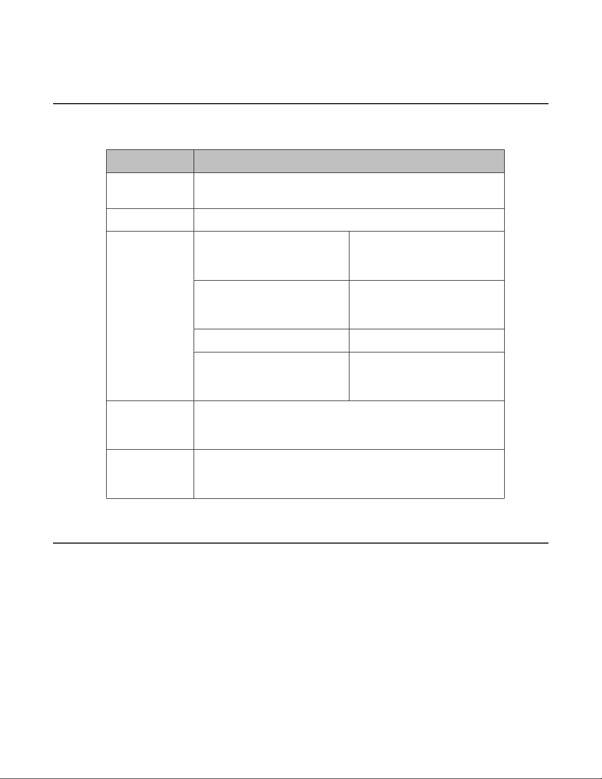
Specifications
Type Description
Dimensions (H
x W x D/Us)
Weight 47.18 to 60 lb (20.41 to 27.22 kg)
Power Input
requirements
(per power
supply)
Power Supply
Output (per
power supply)
BTU Rating
(Maximum)
3.38 x 17.54 x 26. 01 inches (8.59 x 44.54 x 66.07 cm) — 2U
Rated Line Voltage 100 VAC
Rated Input Current 10 A (at 100 VAC)
Rated Input Frequency 50 to 60 Hz
Rated Input Power 980 W (at 100 VAC)
800 W (at 100 VAC)
850 W (at 120 VAC)
1000 W (at 240 VAC)
3350 BTU/hr (at 100 VAC)
3530 BTU/hr (at 120 VAC)
3990 BTU/hr (at 240 VAC)
120 VAC
200 — 240 VAC
9 A (at 120 VAC)
6.1 A (at 200 VAC)
1035 W (at 120 VAC)
1170 W (at 240 VAC)
Environmental specifications
Operating
temperature
Storage
temperature
8 Installing the Avaya S8730 Server for Modular Messaging January 2009
10° to 35° C (50° to 95° F) at sea level with an altitude derating of 1.0° C
for every 305 m (1.8° F for every 1,000 ft) above sea level to a maximum
of 3050 m (10,000 ft), no direct sustained sunlight. Maximum rate of
change is 10° C/hour (18° F/hour).
System performance may be reduced if operating with a fan fault or above
30° C (86° F).
-30° to 60° C (-22° to 140° F). Maximum rate of change is 20° C/hour (36°
F/hour).
Page 9
Front view of server
Operating
relative humidity
Storage relative
humidity
Operating
altitude
Storage altitude 9144 m (30,000 ft). Maximum allowable altitude change rate is 457 m/
Acoustic noise The following are declared A-Weighted sound power levels (LWAd) and
10% to 90% relative humidity, 28° C (82.4° F) maximum wet bulb
temperature, non-condensing.
5% to 95% relative humidity, 38.7° C (101.7° F) maximum wet bulb
temperature, non-condensing.
3050 m (10,000 ft). Maximum allowable altitude change rate is 457 m/
min (1,500 ft/min).
min (1500 ft/min).
declared average bystander position A-Weighted sound pressure levels
(LpAm) when the server is operating in a 23° C ambient environment.
Noise emissions were measured in accordance with ISO 7770 (ECMA 74)
and declared in accordance with ISO 9296 (ECMA 109).
Idle and Operating LWAd, 6.3 B
Idle and Operating LpAm, 47 dBA
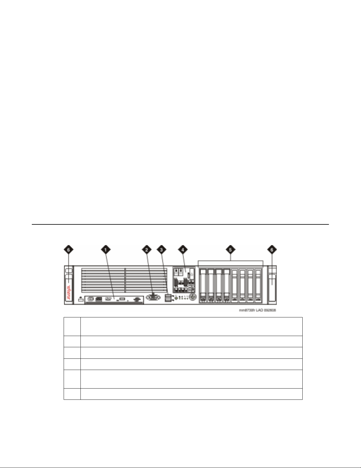
Front view of server
1
Media drive bay. DVD-ROM/CD—RW media drive for model 03; DVD-RAM/
RW media drive for models 04 and 05.
2 Video connector
3 USB connectors (2)
4 Systems Insight Display
5 Hard drive bays. Two 146 GB hard drives for models 03 and 04; four 72 GB
hard drives for model 05.
6 Quick release levers
Installing the Avaya S8730 Server for Modular Messaging January 2009 9
Page 10
Overview of server and components
Back view of server
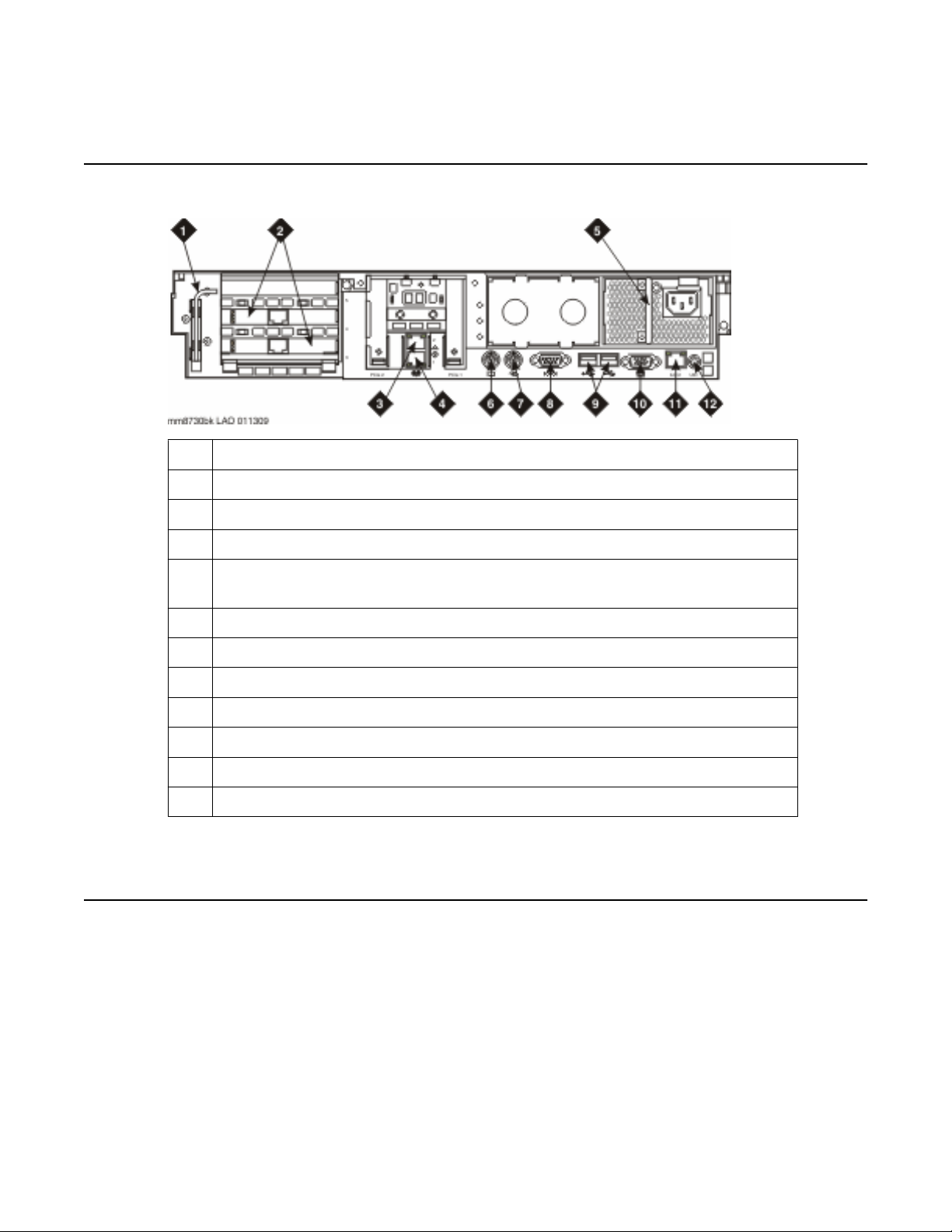
1 T-10/T-15 Torx screwdriver
2 Dialogic port boards. E1–QSIG or T1–QSIG type boards shown.
3 Private LAN Ethernet connection
4 Corporate LAN Ethernet connection
5 Power supply. Two power supplies for Model 05; One power supply for models
03 and 04.
6 Keyboard connector
7 Mouse connector
8 Serial connector
9 USB connectors (2)
10 Video connector
11 iLo 2 connector (not used)
12 Unit Identification (UID) LED button
Related hardware
As part of a total installation, customers may use the following peripheral hardware:
• Uninterruptible power supply (UPS). This can be Avaya or customer provided. It is
required for the Modular Messaging system.
• Ethernet switch. This can be Avaya or customer provided. The Ethernet switch is
required to create the Modular Messaging private LAN in a multiple MAS system. An
Ethernet switch is not required with a single MAS since a crossover cable can be used
to create the private LAN in a single MAS configuration.
10 Installing the Avaya S8730 Server for Modular Messaging January 2009
Page 11

LEDs
LEDs
• KVM switch. Use a keyboard, video, and mouse (KVM) switch to view the different
servers in a Modular Messaging system. The model of KVM switch and the specific
monitor, keyboard, and mouse used can vary from site to site. If the Modular
Messaging system has only two servers, for example an MSS and one MAS, you can
install a 2–port KVM switch. For larger systems, install an 8–port KVM switch. To install
a KVM switch, use the instructions shipped with the switch.
• USB modem. A USB modem is optional, but the customer must provide Services with
some type of remote access to each Modular Messaging server. To install the modem,
use the instructions shipped with it.
The server has LEDs in the following locations:
• Front panel
• Rear panel
• Insight display, located on the front of the server
• Hard drive
• PCI riser cage
• Battery pack
Each SAS hard drive has two LEDs at the base that combine to give information about the
status of the drive. The PCI rise cage has a single LED that indicates whether AC power is
connected or disconnected. The battery pack has four LEDs that combine to give information
about the status of the battery pack and data in the cache.
For additional information about hard drive, PCI riser cage and battery pack LEDs, see
Maintaining the Avaya S8730 Server.
Related topics:
Front panel LEDs on page 12
Back panel LEDs on page 14
Systems Insight Display LEDs on page 15
Installing the Avaya S8730 Server for Modular Messaging January 2009 11
Page 12
Overview of server and components
Front panel LEDs
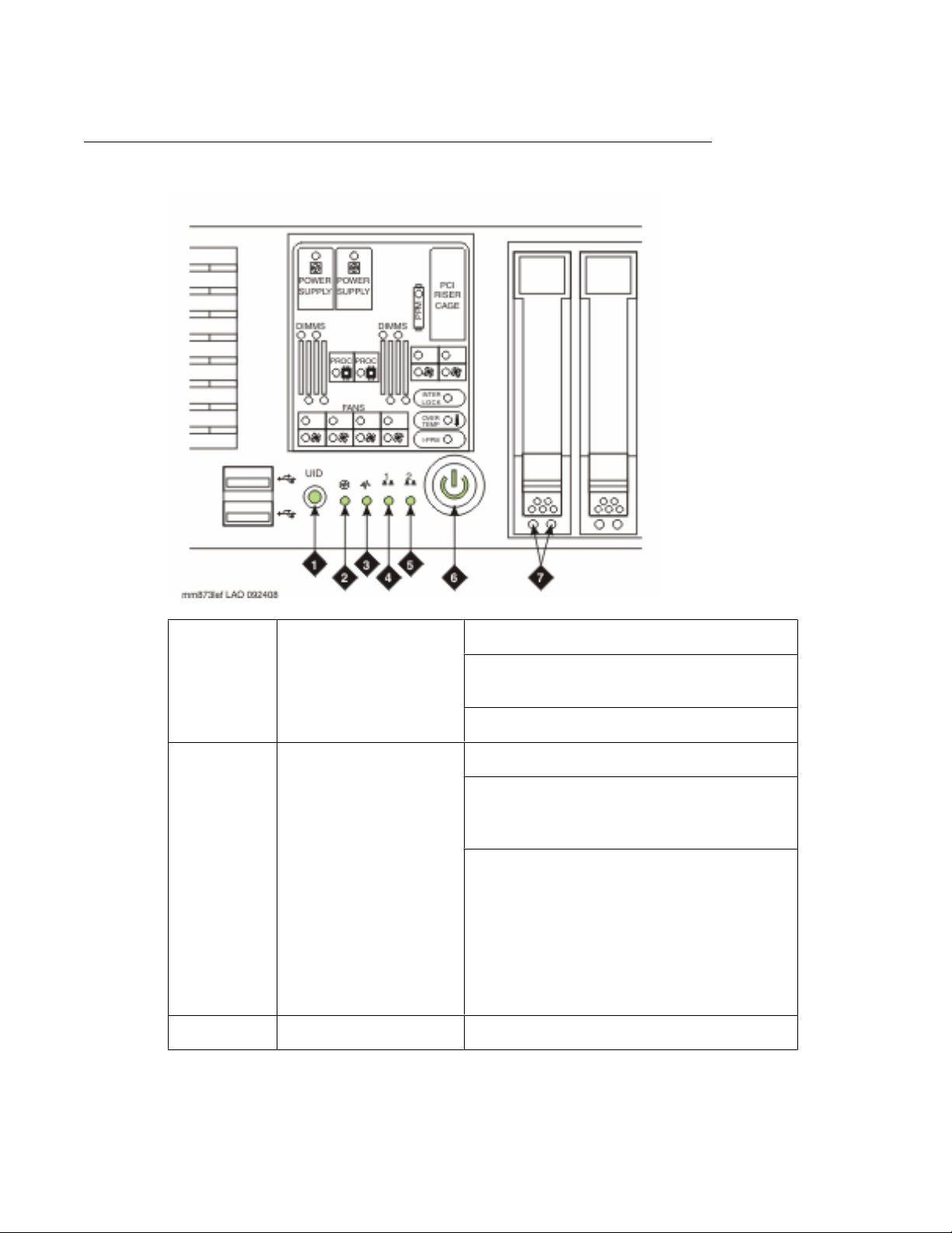
1 UID LED button Blue — Activated
Flashing — System being remotely
managed
Off — Deactivated
2 Internal health LED Green — Normal
Amber — System degraded. To identify
component in degraded state, see
Systems Insight Display LEDs.
Red — System critical. To identify
component in critical state, see Systems
Insight Display LEDs.
For more information about status and
diagnostic information provided by the
Internal health LED in combination with the
Systems Insight Display, see Maintaining
the Avaya S8730 Server.
3 External health LED Green — Normal
12 Installing the Avaya S8730 Server for Modular Messaging January 2009
Page 13
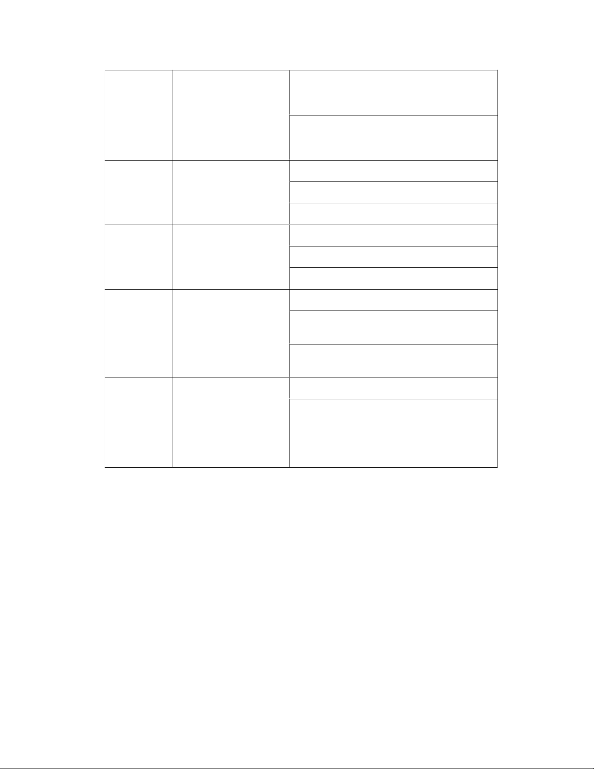
Amber — Power redundancy failure. To
identify component in degraded state, see
Systems Insight Display LEDs.
Red — Critical power supply failure. To
identify component in critical state, see
Systems Insight Display LEDs.
LEDs
4 NIC 1 link/activity LED
Green — Network link
(Corporate Network)
Flashing — Network link and activity
Off — No link to network
5 NIC 2 link/activity LED
Green — Network link
(Private Network)
Flashing — Network link and activity
Off — No link to network
6 Power On/Standby
Green — System on
button/system power
LED
Amber — System shut down, but power
still applied
Off — Power cord not attached or power
supply failure
7 Hard drive LEDs Left-hand LED — Online LED (green)
Right-hand LED — Fault/UID LED (amber/
blue)
For more information about interpreting
Hard drive LEDs, see Maintaining the
Avaya S8730 Server.
Installing the Avaya S8730 Server for Modular Messaging January 2009 13
Page 14
Overview of server and components
Back panel LEDs
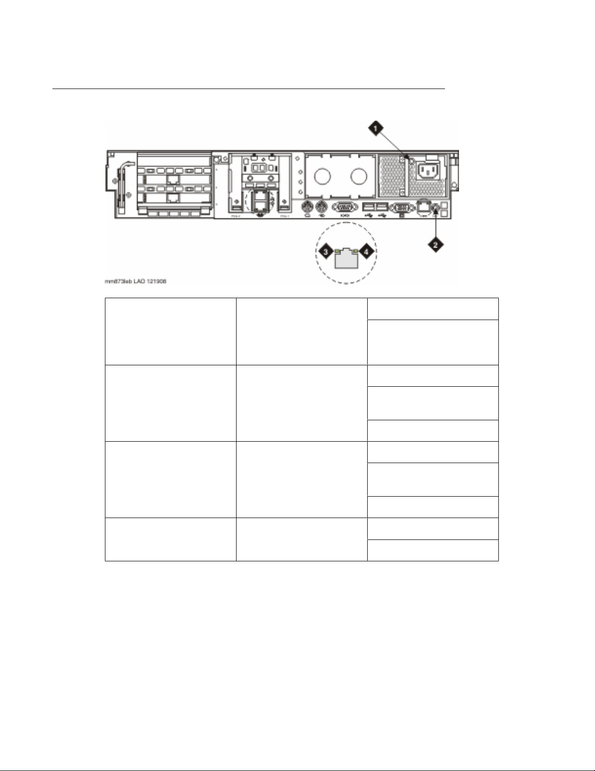
1 Power supply LED Green — Normal
Off — System is off power
or power supply has
failed
2 UID LED button Blue — Activated
Flashing — System being
remotely managed
Off — Deactivated
3 NIC/iLO 2 activity LED Green — Network activity
Flashing — Network
activity
Off — No network activity
4 NIC/iLO 2 link LED Green — Network link
Off — No network link
14 Installing the Avaya S8730 Server for Modular Messaging January 2009
Page 15
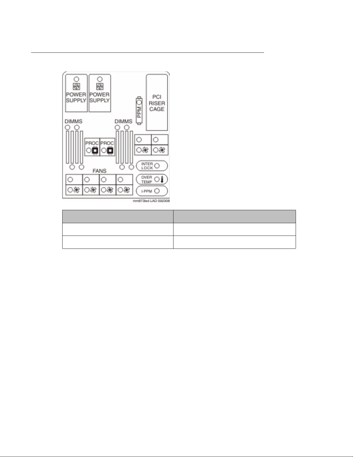
Systems Insight Display LEDs
LEDs
Indication Status
Amber Failure
Off Normal
For more information about status and diagnostic information provided by the Internal health
LED in combination with the Systems Insight Display, see Maintaining the Avaya S8730 Server.
Installing the Avaya S8730 Server for Modular Messaging January 2009 15
Page 16

Overview of server and components
16 Installing the Avaya S8730 Server for Modular Messaging January 2009
Page 17
Chapter 2: Server installation
Customer-provided equipment and access
The customer must provide the following equipment:
• Standard 19–in. 4–post equipment rack properly installed and solidly secured. Rack
must meet the following standards:
- American National Standards Institute (ANSI) and Electronic Industries
Association (EIA) standard ANSI/EIA-310–D-92.
- International Electrotechnical Commission (IEC) 297.
- Deutsche Industrie Norm (DIN) 41494.
• AC power from a nonswitched electrical outlet. Ensure that the AC main outlet used
to power the system through the power cord or the UPS is a grounded outlet. Install
the server within 6 feet (2m) of a grounded AC mains socket-outlet. Do not use
extension cords with the system.
Caution:
System grounding must comply with the general rules for grounding. For more
information, see article 250 of the National Electrical Code (NEC), National Fire
Protection Agency (NFPA). Alternatively, see the applicable electrical code in the
country of installation.
• Access to the Local Area Network (LAN) if required for the installed configuration. The
customer is responsible for:
- Providing the IP address, subnet mask, and gateway information for
administration on the server.
- Providing DNS server IP information and corporate domain names.
• Access to the Telecommunications network.
• For T1 and E1 QSIG connections, the circuits require isolation from exposed lines.
For T1 lines, the customer must provide a CSU (T1) at the building point of entry. This
CSU must be UL listed, CSA Certified, or both. For E1 lines, either the network provider
or the customer must provide a CSU (E1) or equivalent protection. The protection must
have the product safety approvals required by the local jurisdictions.
Installing the Avaya S8730 Server for Modular Messaging January 2009 17
Page 18

Server installation
Avaya-provided equipment
Avaya provides the following equipment:
• S8730 server and power cord. Use only the power cord provided with the server.
• 2 U Quick Deploy Rail System kit.
• Ethernet switch. The Ethernet switch is required only for an MSS configuration with
more than one MAS. It can be customer provided.
• Ethernet crossover cable. The crossover cable is used only for an MSS configuration
with one MAS. It can be used in place of an Ethernet switch to set up the private
network.
• Ethernet LAN cables.
• USB modem. The modem is optional and can be customer provided. If a modem is
not used, remote access must be provided for services by another means.
• Dialogic port board cables. Dialogic boards are pre-installed in all systems except
those using IP H.323 and IP SIP integration. Systems ship with port board cables
appropriate to the type of switch integration.
• Monitor, keyboard and mouse. These are optional and can be customer provided.
• 2–port KVM switch for a two-server system or 8–port KVM switch for multiple-server
system. Optional, other similar types of devices can be used.
• Uninterruptible power supply (UPS). A UPS is required, but it can be customer
provided.
Recommended tools and supplies
• #2 crosspoint (Phillips) screwdriver
• A medium-width flat-blade screwdriver
• T-15 Torx screwdriver (attached to rear of server)
• A small pair of needlenose pliers
• A small pair of wire cutters
• Masking tape or felt-tip pen for marking mounting holes
• A volt/ohm meter
18 Installing the Avaya S8730 Server for Modular Messaging January 2009
Page 19

Recommended test equipment
Verify that the following test equipment will be available when installation and configuration of
the system is complete:
• At least two telephones connected through the switch or private branch exchange
(PBX). The telephones must be of the same type as most of the telephones the
customer plans to use on the system.
- Preferably the test telephones will have a data display for testing integration
and the Find Me and Call Me features.
- If the message waiting indicator (MWI) for the system is a lamp, the test
telephone must be equipped with a lamp. If the MWI is a stutter tone, the
telephone must be able to provide the stutter notification.
- Place the test telephone so you can easily see the monitor while using the
telephones.
• Access to a fax machine if fax messaging will be installed on the system.
Recommended test equipment
Safety instructions
Use the following safety guidelines to ensure your personal safety and to help protect your
system and working environment from potential damage.
• Use only the power cord provided with the server.
• Do not place objects on AC power cords or cables. Arrange them so that no one may
accidentally step on or trip over them.
• Place the server away from radiators, heat registers, stoves, amplifiers or other
sources of heat.
• Always use a UPS to protect against fluctuations or temporary interruptions in the
power supply.
Observe the following precautions for rack stability and safety. Also refer to the rack installation
documentation accompanying the rack for specific caution statements and procedures.
Systems are considered to be components in a rack. Thus, "component" refers to any system
as well as to various peripherals or supporting hardware.
Caution:
Before installing systems in a rack, install front and side stabilizers on stand-alone racks or
the front stabilizer on racks joined to other racks. Failure to install stabilizers accordingly
before installing systems in a rack could cause the rack to tip over, potentially resulting in
bodily injury under certain circumstances. Therefore, always install the stabilizer(s) before
installing components in the rack.
If you are installing more than one server, install the mounting rails so that the first server is
installed in the lowest available position in the rack. If you are installing a UPS in the same
Installing the Avaya S8730 Server for Modular Messaging January 2009 19
Page 20
Server installation
rack as the server(s), install the UPS in the lowest available position in the rack and the
servers above it.
After installing system/components in a rack, never pull more than one component out of
the rack on its slide assemblies at one time. The weight of more than one extended
component could cause the rack to tip over and may result in serious injury.
It is your responsibility to ensure that the final combination of system and rack complies with
all applicable safety standards and local electric code requirements.
System rack kits are intended to be installed in a rack by trained service technicians.
Always load the rack from the bottom up, and load the heaviest item in the rack first.
Make sure that the rack is level and stable. Be sure the leveling jacks (feet) extend to the
floor and that the full weight of the rack rests firmly on the leveling jacks.
Use caution when pressing the component rail release latches and sliding a component into
or out of a rack; the slide rails can pinch your fingers.
Do not overload the AC supply branch circuit that provides power to the rack. The total rack
load should not exceed 80 percent of the branch circuit rating.
Note:
Caution:
Ensure that proper airflow is provided to components in the rack. Do not block ventilation
openings or allow other equipment to block airflow to the server. If the 42U rack includes
closing front and rear doors, allow 5,350 square cm (830 square inches) of holes evenly
distributed from top to bottom to permit adequate airflow (equivalent to required 64 percent
open area for ventilation). Clearance between the server and the side panel of the rack must
be a minimum of 7 cm (2.75 inches).
Do not step on or stand on any component when servicing other components in a rack.
Installation checklist
#
1 Verify that all equipment is on
site
Task Notes
Compare the list of items that were
ordered to the contents of the boxes.
Use the inventory list provided by your
project manager; do not rely on the
packing slips inside the boxes for the
correct information.
Save at least one empty carton and a
set of packing materials in case the
server must be returned for service.
20 Installing the Avaya S8730 Server for Modular Messaging January 2009
Page 21
# Task Notes
Installation checklist
2 Record the MSS serial
number and MAS Windows
product key
3 Verify that rack is installed to
code
4 Verify that rack is grounded
per local code
5 Remove cabinet doors, if
necessary
6 Marking the rack on page
22
7 Attaching rails to the server
on page 23
8 Attaching the rails to the rack
on page 24
9 Installing the server in the
rack on page 25
10 Corporate and private LAN
connections on page 26
These will be required later for
configuring the system software.
See cabinet manufacturer's
documentation.
11 Connecting Dialogic port
boards on page 29
12 Install the optional KVM
switch
13 Install optional modems for
MAS and MSS
14 Connecting power on page
30
15 Replace the cabinet doors, if
necessary
Follow manufacturer's instructions.
Follow manufacturer's instructions.
See cabinet manufacturer's
documentation.
Installing the Avaya S8730 Server for Modular Messaging January 2009 21
Page 22
Server installation
Marking the rack
Prerequisites
The rack must be installed. If installing the server in a cabinet, then the doors must be removed.
You must allow 2 U (89 mm, or 3.5 in.) of vertical space for each server you install in the rack.
Rack cabinets that meet EIA-310 standards have an alternating pattern of three holes per rack
unit with center-to- center hole spacing (beginning at the top hole of a 1-U space) of 15.9 mm,
15.9 mm, and 12.7 mm (0.625 in., 0.625 in., and 0.5 in.) for the front and back vertical rails.
Rack cabinets may have round or square holes.
Note:
The vertical rails may be marked by horizontal lines and numbers in 1-U increments. If you
want, you can make a note of the number marking on the rack’s vertical rail. It is not
necessary to mark or place tape on the rack
1. Place a mark (or tape) on the rack's front vertical rails where you want to locate the
bottom of the server.
The bottom of each 1-U space is at the middle of the narrowest metal area between
holes (marked with a horizontal line on some rack cabinets).
2. Place a mark 3.5 in. (89 mm) above the original mark you made (or count up six
holes in a rack) and mark the rack's front vertical rails with a felt-tipped pen or
masking tape. If you counted holes, place a mark just above the top hole.
This mark or piece of tape indicates where the system's upper edge will be located
on the vertical rails.
22 Installing the Avaya S8730 Server for Modular Messaging January 2009
Page 23
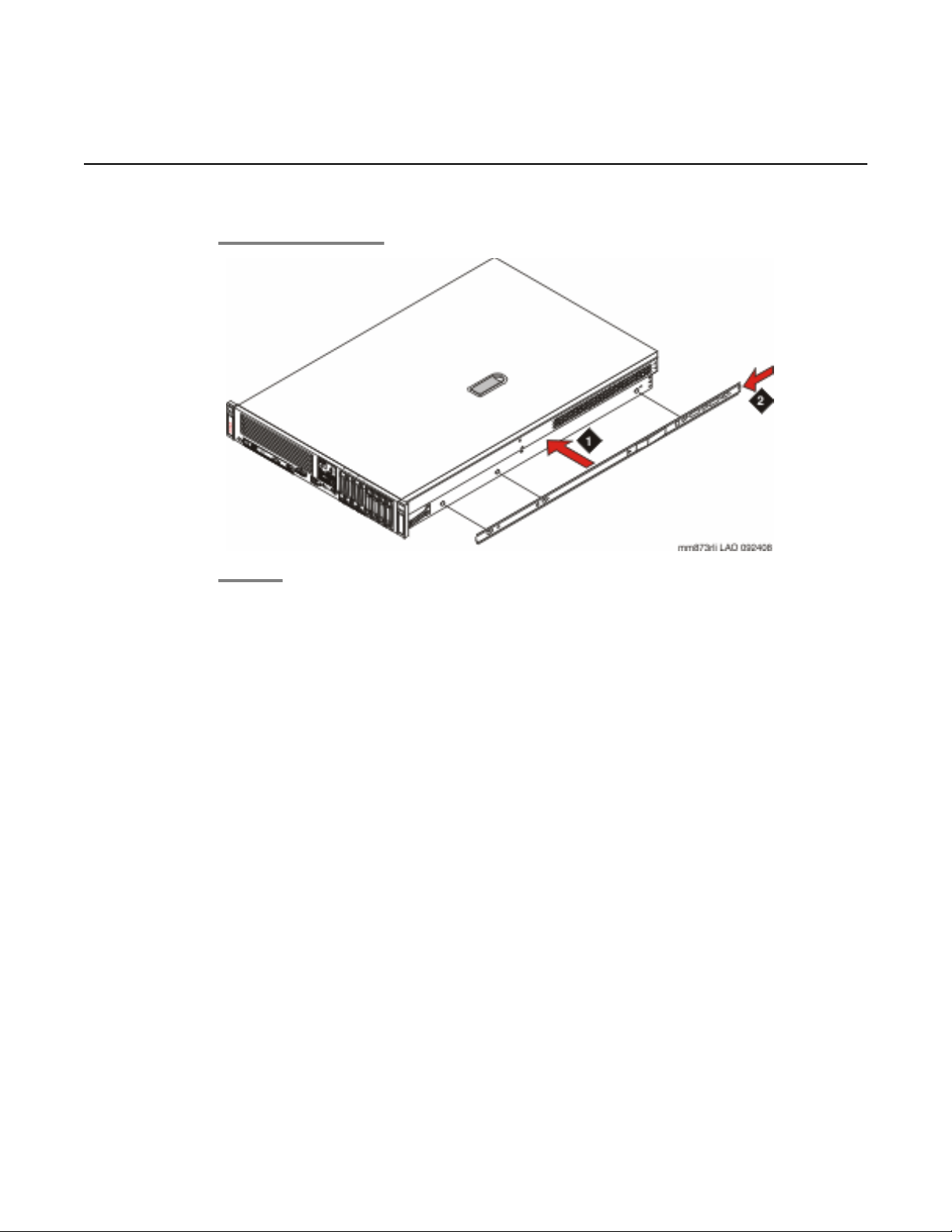
Attaching rails to the server
Attaching rails to the server
Installing the Avaya S8730 Server for Modular Messaging January 2009 23
Page 24
Server installation
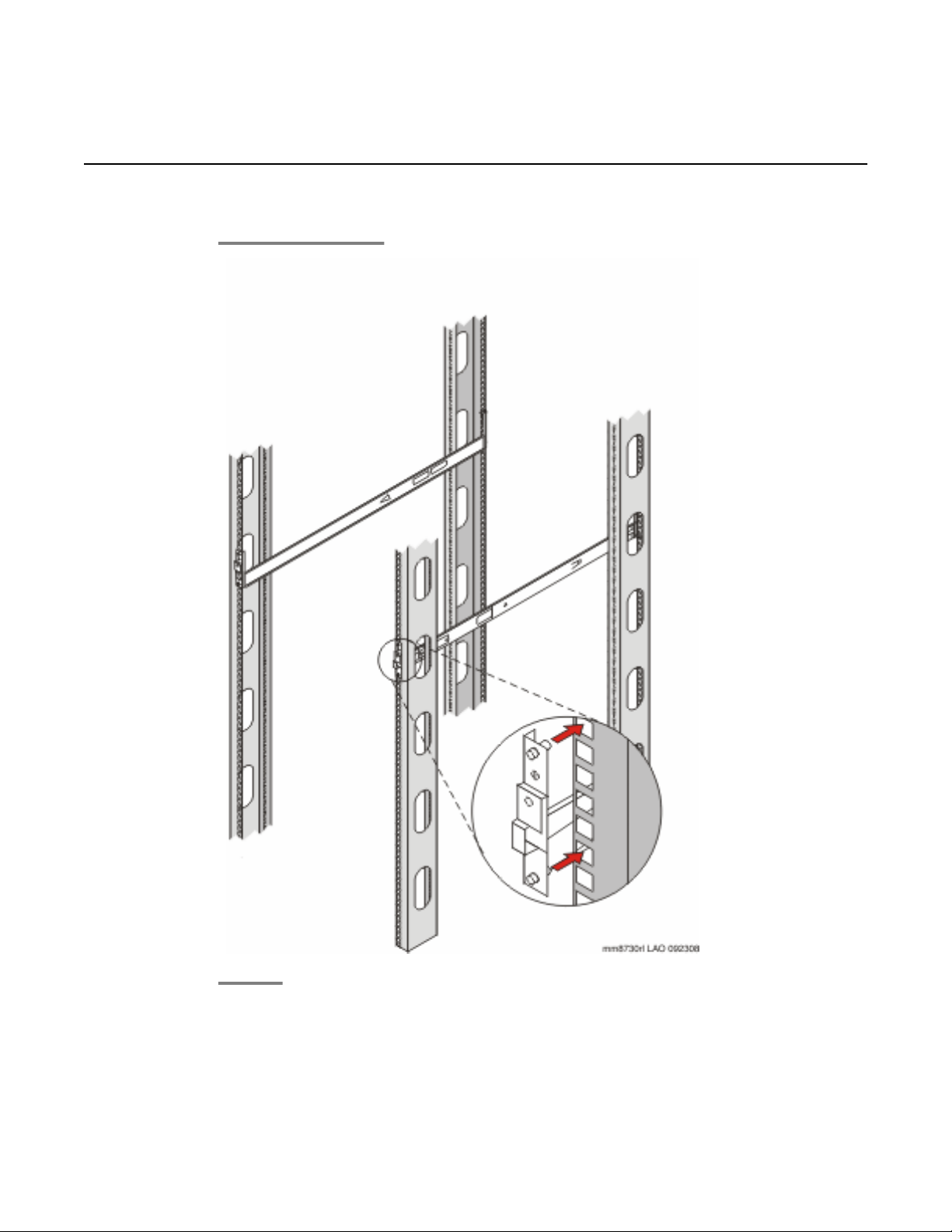
Attaching the rails to the rack
24 Installing the Avaya S8730 Server for Modular Messaging January 2009
Page 25
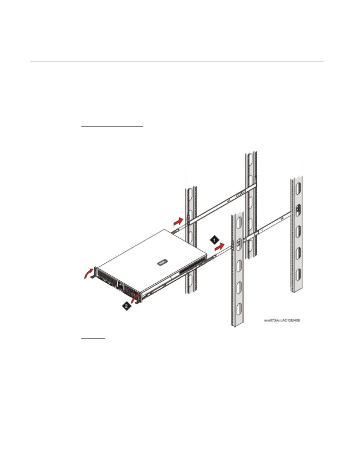
Installing the server in the rack
Prerequisites
The rails must be attached to the server and the rack before installing the server in the rack.
If the server is being installed in a cabinet, remove the doors, following the cabinet
manufacturer's instructions.
Installing the server in the rack
Next steps
If the server is being installed in a cabinet, reattach the doors, following the cabinet
manufacturer's instructions.
Installing the Avaya S8730 Server for Modular Messaging January 2009 25
Page 26
Server installation
Corporate and private LAN connections
Each Modular Messaging system must be connected to either the corporate LAN or the private
LAN in one of the following ways:
• For a Microsoft Exchange or an IBM Domino configuration, connect each MAS to the
corporate LAN.
• For an Avaya MSS configuration, connect the MSS to all Avaya MAS units and, if
present, the supplementary server through a private LAN. If the Modular Messaging
system consists of the MSS and a single MAS, you can use a crossover cable to make
the private LAN connection. If the Modular Messaging system has more than one
MAS, you must use an Ethernet switch to set up the private LAN.
• Additionally, for an Avaya MSS configuration, if the customer wants access to client
applications, connect each server in the voice domain to the corporate LAN.
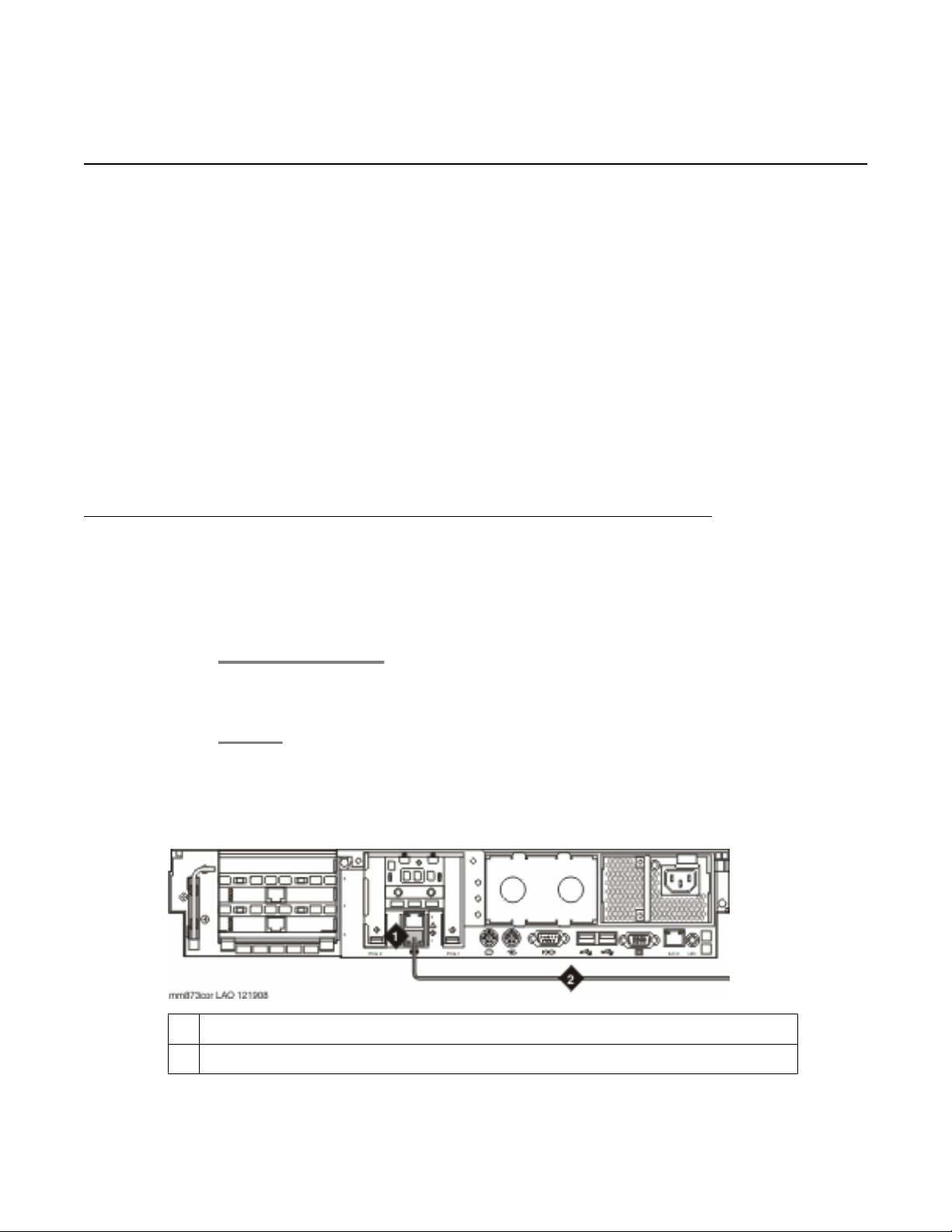
Connecting the MAS to the Corporate LAN
Connecting the MAS
For a Microsoft Exchange or IBM Domino configuration, attach each MAS to the
corporate LAN with a standard Ethernet cable.
MAS Corporate LAN connection
1
Ethernet interface for the corporate LAN
2 Ethernet cable to the corporate LAN
26 Installing the Avaya S8730 Server for Modular Messaging January 2009
Page 27
Corporate and private LAN connections
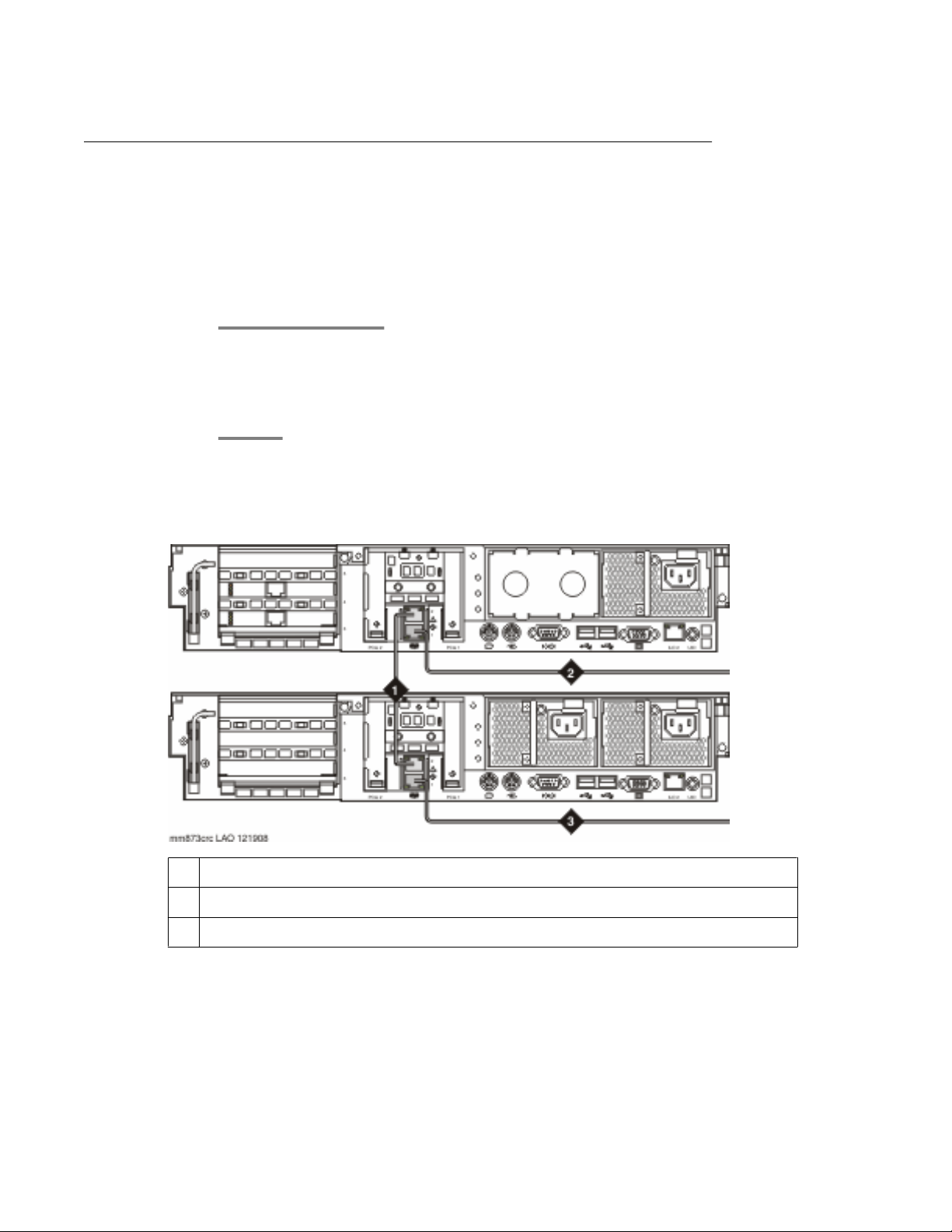
Connecting the MAS and MSS with a crossover cable
Connecting the MAS and MSS
When you have an MSS with a single MAS, you can use a crossover cable connection to create
the Private LAN for Modular Messaging
1. With the crossover cable connect the MAS to the MSS.
2. Connect each server, as needed, to the corporate LAN with a standard Ethernet
cable.
Crossover cable connections
1 Private LAN connection using a crossover cable
2 MAS Ethernet cable to the corporate LAN
3 MSS Ethernet cable to the corporate LAN
Installing the Avaya S8730 Server for Modular Messaging January 2009 27
Page 28
Server installation
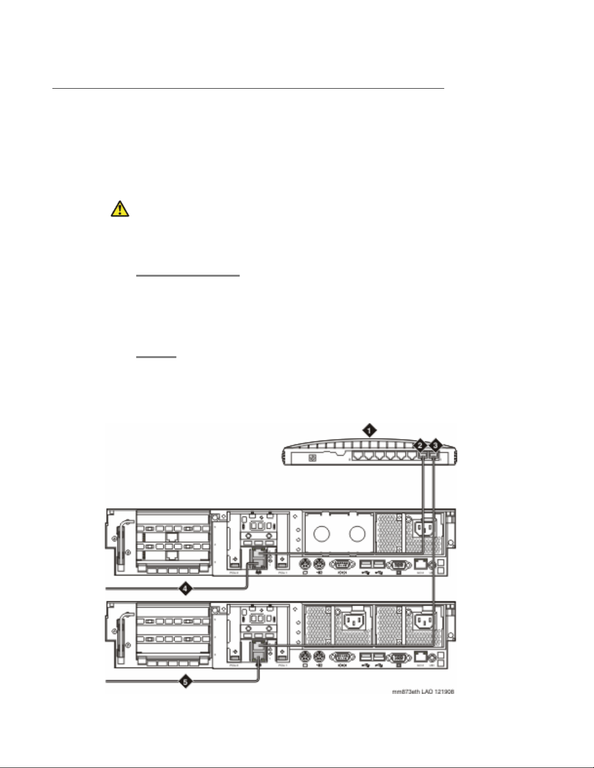
Connecting the MAS and MSS with an Ethernet switch
Connecting the MAS and MSS
When you have an MSS with more than one MAS, you must use an Ethernet switch to create
the Private LAN for Modular Messaging.
Caution:
In a multiple-MAS system, do not connect any MASs except the first to the Ethernet switch
until you are ready to configure that server. Otherwise, the unused MAS might create errors
on the private network even if you turn off the server.
1. Connect the Private LAN connection on the MSS and each MAS to the Ethernet
switch.
2. Connect each server, as needed, to the corporate LAN with a standard Ethernet
cable.
Ethernet switch connections
28 Installing the Avaya S8730 Server for Modular Messaging January 2009
Page 29
1 Ethernet switch
2 MAS1 Ethernet connection to private LAN. Usually this connection uses
Ethernet switch port 2. Subsequent MASs and optional servers use ports 3, 4,
and so on.
3 MSS Ethernet connection to private LAN. Usually this connection uses Ethernet
switch port 1.
4 MAS Ethernet connection to the corporate LAN.
5 MSS Ethernet connection to the corporate LAN.
Connecting MAS port boards
Connecting MAS port boards
Connecting Dialogic port boards
Skip this procedure if the Modular Messaging system uses an IP H.323 or IP SIP switch
integration. These integrations do not use port boards.
The server has pre-installed Dialogic port boards. Since Modular Messaging uses the new
PCI-e version of the Dialogic boards, do not move Dialogic boards from an S3500 server if
upgrading to the S8730 server.
Use the type of cable appropriate to the switch integration to connect the Dialogic port
board to the corporate telephone switching system. The organization responsible for
maintaining the corporate switch must make the connection to the telecommunications
system.
Supported port board connections
The server supports the following port board connections:
• Analog using a standard RJ-11 tip/ring cord or individual tip/ring cables and a 12–
port harmonica.
• E1–QSIG and T1–QSIG using an RJ-48C Ethernet cable.
• Dialogic Set Emulation (DSE) boards using a D/82U cable.
Installing the Avaya S8730 Server for Modular Messaging January 2009 29
Page 30
Server installation
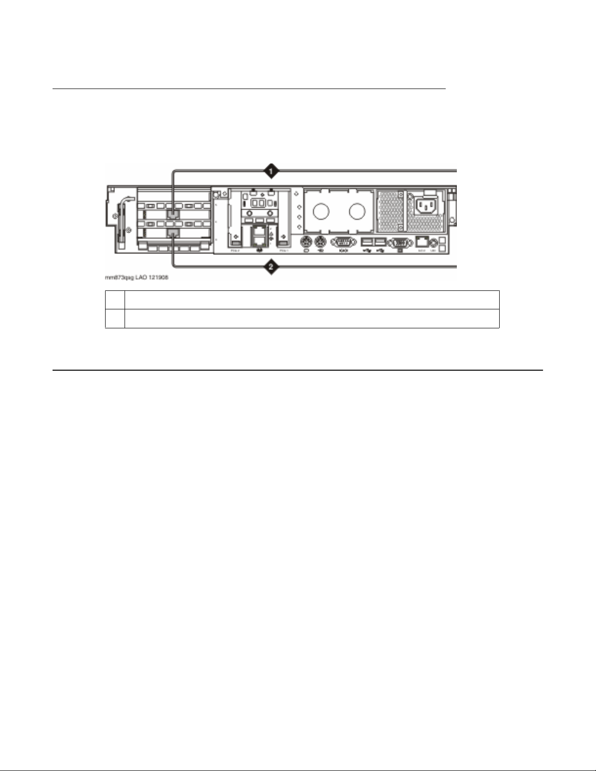
Port board connections
The graphic illustrates two E1–QSIG or T1–QSIG connections from MAS port boards to the
corporate telephone switching system. DSE and analog boards connect at the same location
on the back of the server.
1 Port board connection to corporate switch
2 Port board connection to corporate switch
Connecting power
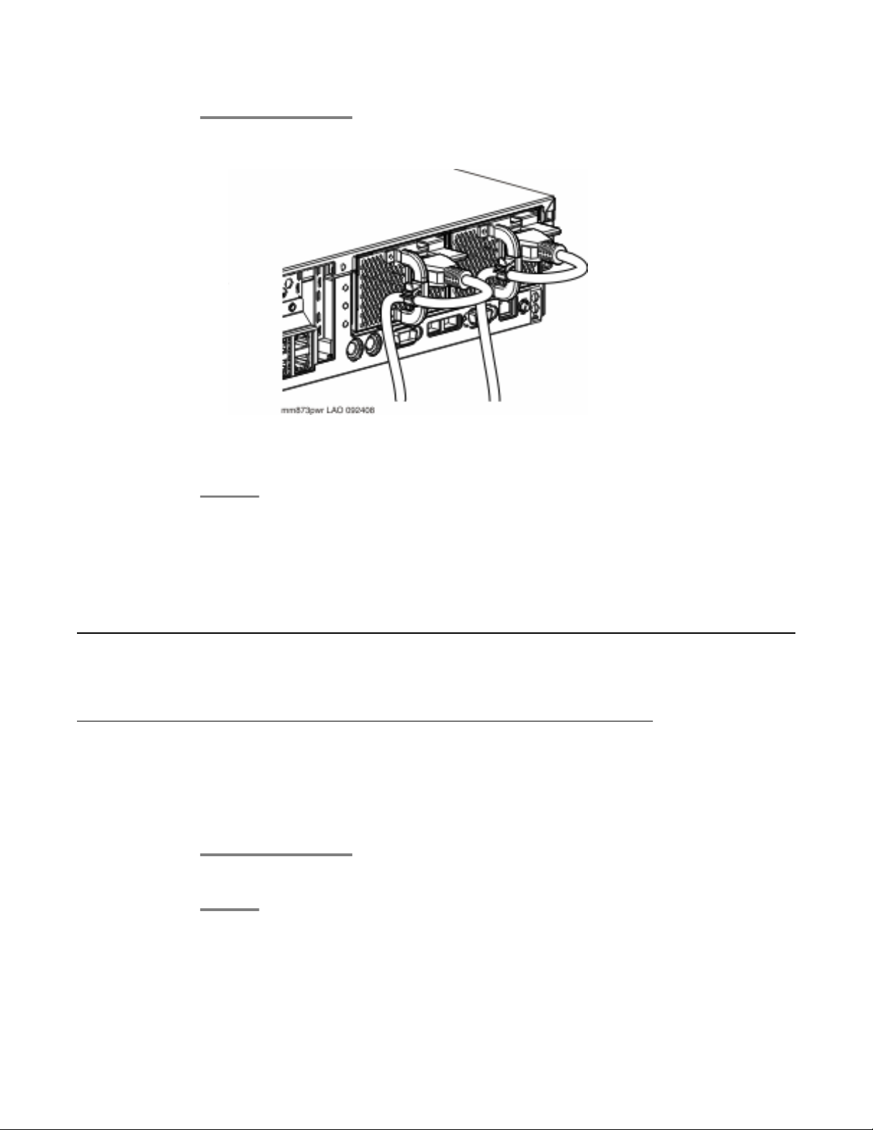
The following graphic illustrates the S8730 server with two power supplies. Models 03 and 04
ship with a single power supply; model 05 ships with the illustrated duplicate power supply.
30 Installing the Avaya S8730 Server for Modular Messaging January 2009
Page 31
Troubleshooting the installation
1. Plug one end of the power cord into the back of the server and connect the power
cord anchor to the handle of the power supply.
2. Plug the other end of the power cord into the UPS.
3. To turn the server on, press the power button on the front of the server.
Next steps
Refer to specific product documentation for information on installing and configuring software.
Troubleshooting the installation
Avaya and customer equipment is missing
Contact Avaya
Contact the Avaya project manager.
Installing the Avaya S8730 Server for Modular Messaging January 2009 31
Page 32

Server installation
The server has no power or a power fault
The server does not power on.
The system power, external health, or internal health LEDs indicate power faults.
Internal health LED is red or amber
1. Identify any component identified by a health LED.
2. Reseat the component and check it for loose connections.
3. If the condition still exists, you may need to replace the component. For more
information, see Maintaining the Avaya S8730 Server.
System Power LED is off
1. Make sure power cords are plugged into the back of the server and into a
nonswitched outlet or UPS.
2. Make sure the UPS is plugged into a nonswitched outlet.
3. Make sure the outlet has power.
4. Push the power button on the front of the server.
5. Reseat the power supply.
6. If the condition still exists, you may need to replace the power supply. For more
information, see Maintaining the Avaya S8730 Server.
System Power LED is Amber or Green
If the external health LED is red or amber complete the following steps. If the external health
LED is not red or amber than proceed as you would if the system power LED was off.
1. If the server has a single power supply, and the external health LED is red, replace
the power supply. For more information, see Maintaining the Avaya S8730 Server. If
not, continue with the next step.
2. Press the Power-On Standby button.
32 Installing the Avaya S8730 Server for Modular Messaging January 2009
Page 33

Troubleshooting the installation
3. If the external health LED is red or amber, replace the power supply that does not
have a green LED. For more information, see Maintaining the Avaya S8730 Server.
4. If the external health LED is not red or amber, check for a loose power cord on one of
the redundant power supplies.
Installing the Avaya S8730 Server for Modular Messaging January 2009 33
Page 34

Server installation
34 Installing the Avaya S8730 Server for Modular Messaging January 2009
Page 35

Index
A
acoustic noise levels ....................................................8
altitude
operating ................................................................8
storage ...................................................................8
attach rails to rack ......................................................24
attach rails to server ...................................................23
Avaya-provided equipment .........................................18
B
back panel LEDs ........................................................14
BTU rating ....................................................................8
K
KVM switch .................................................................10
L
LEDs ..........................................................11, 12, 14, 15
back panel ............................................................14
front panel ............................................................12
Systems Insight Display .......................................15
legal notices .................................................................2
M
C
components ..................................................................5
corporate LAN
connecting MAS ...................................................26
with crossover connection ....................................27
with Ethernet switch .............................................28
crossover cable connection ........................................27
customer-provided equipment ....................................17
D
Dialogic boards .....................................................29, 30
Dialogic port boards .....................................................7
E
environmental specifications ........................................8
Ethernet connection
MAS .....................................................................26
with crossover connection ....................................27
with Ethernet switch .............................................28
Ethernet switch ...........................................................10
mark the rack ..............................................................22
modem .......................................................................10
N
notices, legal ................................................................2
P
port boards ........................................................7, 29, 30
power
input requirements .................................................8
power supply output ...............................................8
power cord ..................................................................30
private LAN
with crossover cable ............................................27
with Ethernet switch .............................................28
R
recommended test equipment ....................................19
recommended tools ....................................................18
relative humidity ...........................................................8
F
S
front panel LEDs .........................................................12
safety instructions .......................................................19
I
install server in rack ....................................................25
installation checklist ....................................................20
Installing the Avaya S8730 Server for Modular Messaging January 2009 35
server back view .........................................................10
server front view ...........................................................9
specifications ................................................................8
Systems Insight Display LEDs ...................................15
Page 36

Index
T
temperature
operating ................................................................8
storage ...................................................................8
test equipment ............................................................19
troubleshooting
missing equipment ...............................................31
power problems ...................................................32
turning on server ........................................................30
U
UPS ............................................................................10
36 Installing the Avaya S8730 Server for Modular Messaging January 2009
 Loading...