

Avaya S8700, S8730, S8720, S8710 Quick Start Manual

Quick Start
for Hardware Installation Avaya S8700-Series Servers
January 2008
555-245-703
Issue 8
700436827

© 2008 Avaya Inc.
All Rights Reserved.
Notice
While reasonable efforts were made to ensure that
the information in this document was complete and
accurate at the time of printing, Avaya Inc. can
assume no liability for any errors. Changes and
corrections to the information in this document may
be incorporated in future releases.
For full support information, please see the
complete document, Avaya Support Notices for
Hardware Documentation, document number
03-600759.
To locate this document on our Web site,
simply go to http://www.avaya.com/support
search for the document number in the search
box.
Documentation disclaimer
Avaya Inc. is not responsible for any modifications,
additions, or deletions to the original published
version of this documentation unless such
modifications, additions, or deletions were
performed by Avaya. Customer and/or End User
agree to indemnify and hold harmless Avaya,
Avaya's agents, servants and employees against
all claims, lawsuits, demands and judgments
arising out of, or in connection with, subsequent
modifications, additions or deletions to this
documentation to the extent made by the Customer
or End User.
Link disclaimer
Avaya Inc. is not responsible for the contents or
reliability of any linked Web sites referenced
elsewhere within this documentation, and Avaya
does not necessarily endorse the products,
services, or information described or offered within
them. We cannot guarantee that these links will
work all of the time and we have no control over the
availability of the linked pages.
and
Warr anty
Avaya Inc. provides a limited warranty on this
product. Refer to your sales agreement to establish
the terms of the limited warranty. In addition,
Avaya’s standard warranty language, as well as
information regarding support for this product, while
under warranty, is available through the following
Web site:
http://www.avaya.com/support
Copyright
Except where expressly stated otherwise, the
Product is protected by copyright and other laws
respecting proprietary rights. Unauthorized
reproduction, transfer, and or use can be a criminal,
as well as a civil, offense under the applicable law.
Avaya support
Avaya provides a telephone number for you to use
to report problems or to ask questions about your
product. The support telephone number
is 1-800-242-2121 in the United States. For
additional support telephone numbers, see the
Avaya Web site: http://www.avaya.com/support
.
.
Process and Specifications
1 Verifying the Equipment
2 Installing the SNMP Module in the UPS
3 Installing the Optional Second Hard Drive
4 Installing the DAL2 Card
5 Installing the Hardware in the Rack
6 Connecting the Cables
7 Configuring the UPS and the Ethernet Switch
8 Connecting the Laptop
9 Connecting to the G650 Media Gateway
10 Troubleshooting
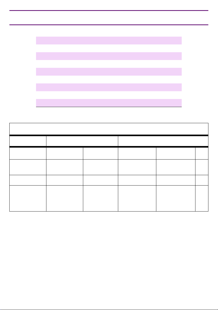
Hardware Specifications
Weight Dimensions
Equipment English (lb) Metric (kg) English (in) Metric (cm) Us
S8730, S8720, or
S8710 Server
UPS >34 >15 3.5 x 17 x 19 9 x 43 x 48 2
Ethernet switch
C363T
C364T
60 27 3.4 x 17.5 x 26 8.6 x 45 x 66 2
11
11
5
5
1.75 x 17 x 14.5
1.75 x 17 x 14.5
4.5 x 43 x 36.5
4.5 x 43 x 36.5
Issue 8 January 2008 3
1
1
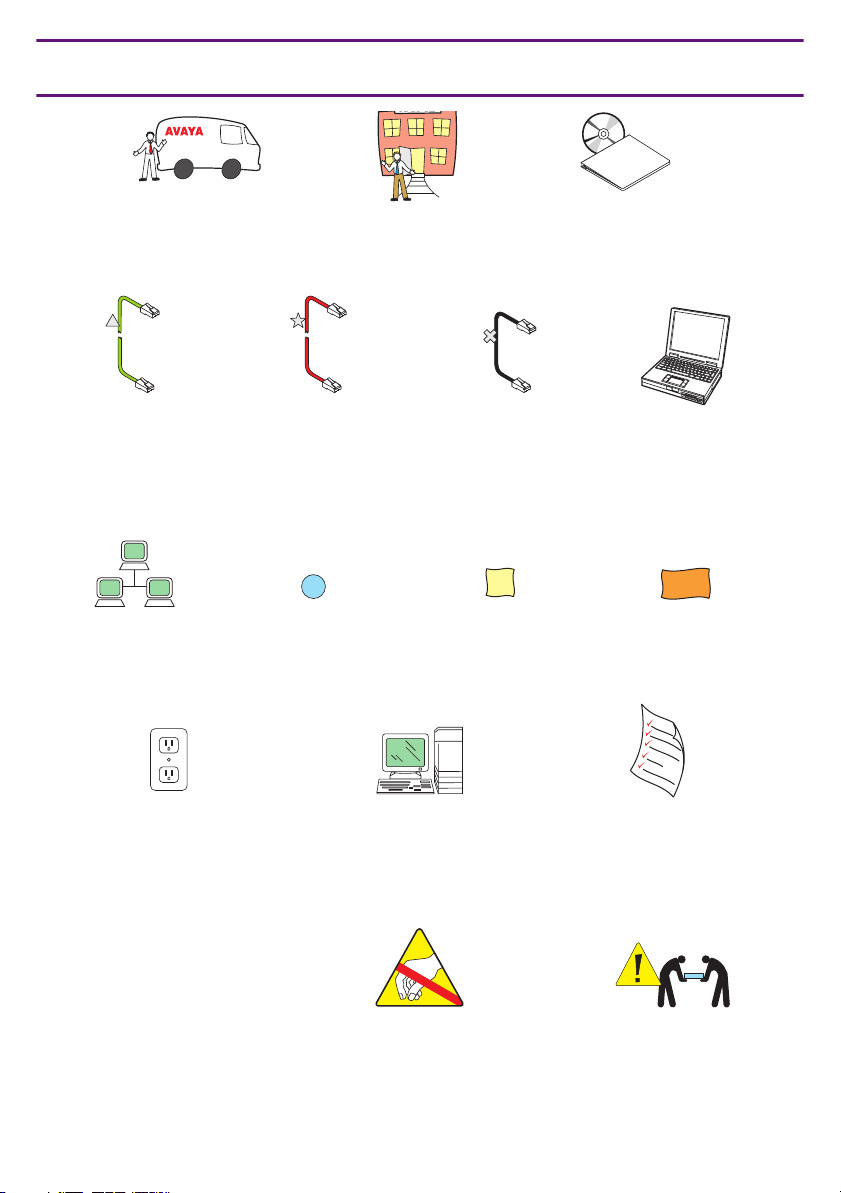
Legend
Documentation
Avaya technician
or business partner
Green
straight-through
CAT5 cable
Customer
network
Red
straight-through
CAT5 cable
2
Sequence step
Customer
Crossover
CAT5 cable
D
Duplex
reliability
Product
documentation
Services
laptop
H/C
High/Critical
reliability
Nonswitched
electrical outlet
87qslgnd KLC 021605
4 Quick Start for Hardware Installation: Avaya S8700-Series Servers
System
administration
Anti-static wrist
ground strap
required
Filled-out Electronic
Pre-Installation
Worksheet (EPW)
Warning!
Use 2 people
to lift equipment
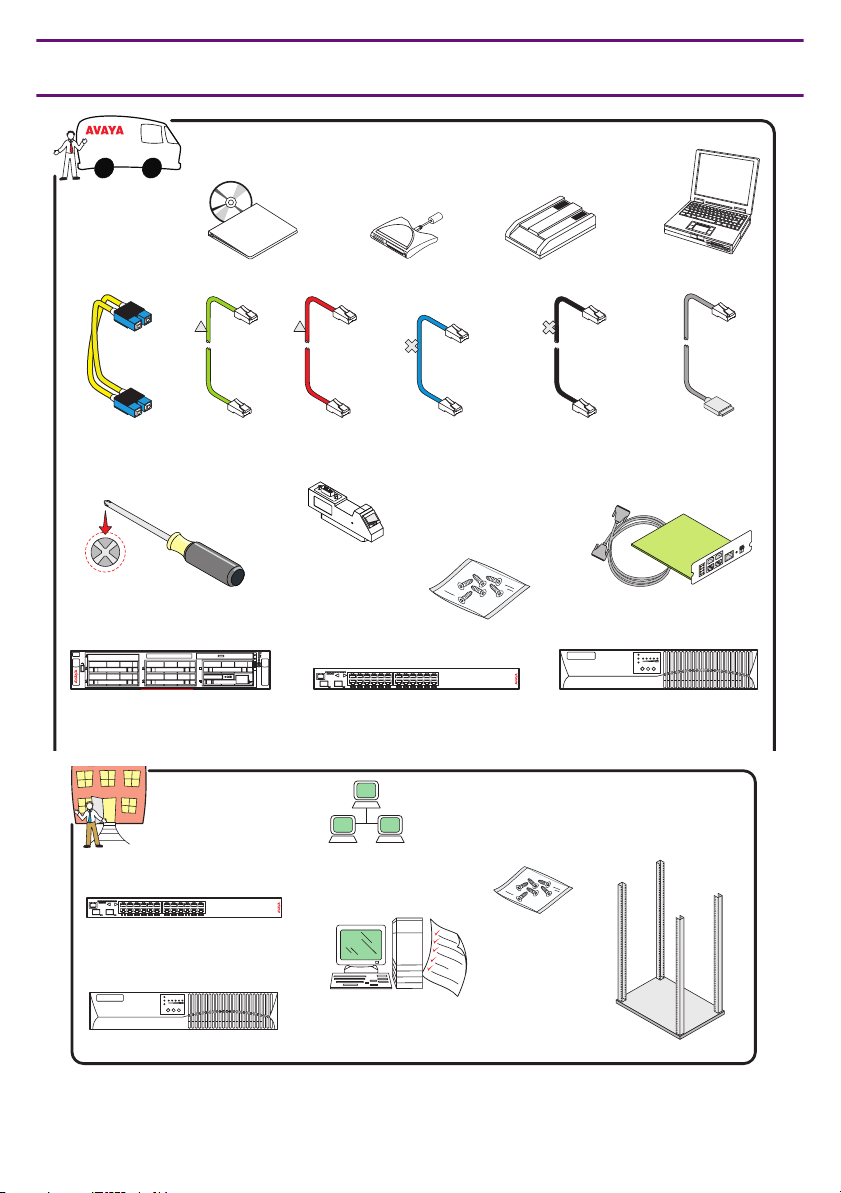
1 Verifying the Equipment
Product
documentation Modem (2)
Compact flash
reader and
flashcard
Documentation
CAT5
(4 - 68)
CAT5
CAT5
(1)
Laptop to
cable
T
T
E
E
N
N
R
R
E
E
H
H
T
T
E
E
T
T
b
b
0
0
0
0
1
1
/
/
0
0
1
1
server cable
(1)
Fiber
cable
CAT5
(4 -68)
IPSI control network cables Duplication
Screws
IPSI adapter
(1 - 128)
Cross-point screwdriver
5
5
4
4
1
3
2
2
x
le
p
im
S
0
0
LNKCOL Tx Rx FDX HspdLAG PoE
24681012 141618202224
ROUTSYS PWR
S1 S2
1357911 13 15 17 19 21 23
COMPACT
2
1
h
disc
c
2
1
h
c
I
D
U
x
le
p
u
D
1
3
Server (2) Ethernet switch * (1 or more) UPS* (2)
(1)
Services
laptop
Modem cable
SNMP module
and cable (2)
(2)
f
f
O
n
O
1 2
Ethernet switch*
LNKCOL Tx Rx FDXHspd LAG PoE
24681012141618202224
ROUTSYS PWR
S1 S2
1357911 13 15 17 19 21 23
(1 or more)
*Optional
UPS*
(2)
19 in. (48 cm)
data rack (1)
Customer network
Screws
System administration
and filled-out Electronic
Pre-Installation Worksheet
8720qseq2 LAO 102605
Issue 8 January 2008 5
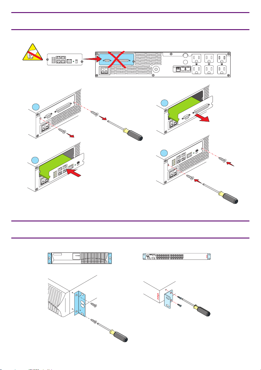
2a Installing the SNMP Module in the UPS
COMM PORT
ISOLATED
IOIOI
Off
On
1 2
ALARM PORT
ISOLATED
COMM PORT
ALARM PORT
IOIOI
1
2
4
ff
3
O
n
O
1 2
87qs2a KLC 010605
2b UPS and Ethernet Switch Mounting Brackets
LNKCOL Tx Rx FDXHspd LAG PoE
2
14365871091211
1413161518172019222124
23S1 S2
ROUTSYS PWR
COMM PORT
ISOLATED
ALARM PORT
IOIOI
ff
O
n
O
1 2
8720qs2b LAO 102005
6 Quick Start for Hardware Installation: Avaya S8700-Series Servers
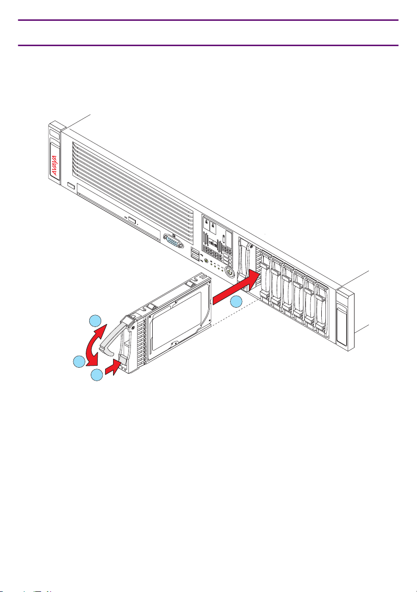
3 Installing an optional second hard drive (S8730)
Note:
Note: To use RAID, available on the S8730 Server only, install an optional second
hard drive.
P
O
W
S
E
U
R
P
P
P
L
O
Y
W
S
E
U
R
P
P
D
L
IM
Y
M
S
P
C
D
R
I
IM
IS
PROC
M
E
C
S
R
PPM
A
G
PROC
E
FA
N
S
I
N
T
E
LOCK
R
UID
OV
E
TEMP
R
I
-P
P
M
1
2
4
2
3
1
8730qsxf LAO 083007
Issue 8 January 2008 7
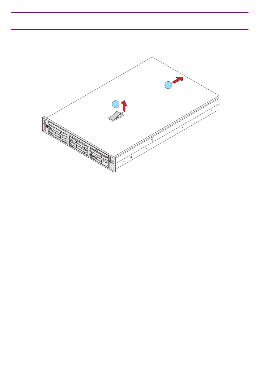
4a Installing the DAL2 Card: Removing the Cover
(S8720 Server shown)
2
1
5
5
4
4
3
3
2
2
C
O
disc
M
P
A
C
T
1
1
0
0
2
h
c
1
h
1
c
x
2
le
p
U
u
I
D
D
x
le
p
im
S
8720qsxa LAO 101206
8 Quick Start for Hardware Installation: Avaya S8700-Series Servers
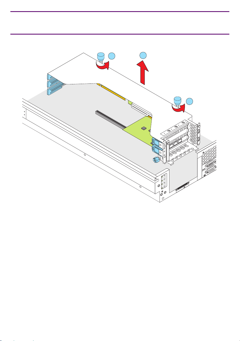
4b Installing the DAL2 Card: Removing the PCI Riser Cage
(S8720/S8710)
8720qsxb LAO 101206
1
2
1
3
z
G
M
0
0
1
2
z
G
M
0
0
1
1
z
G
3 M
3
3
2
VD
1
I
C
Issue 8 January 2008 9
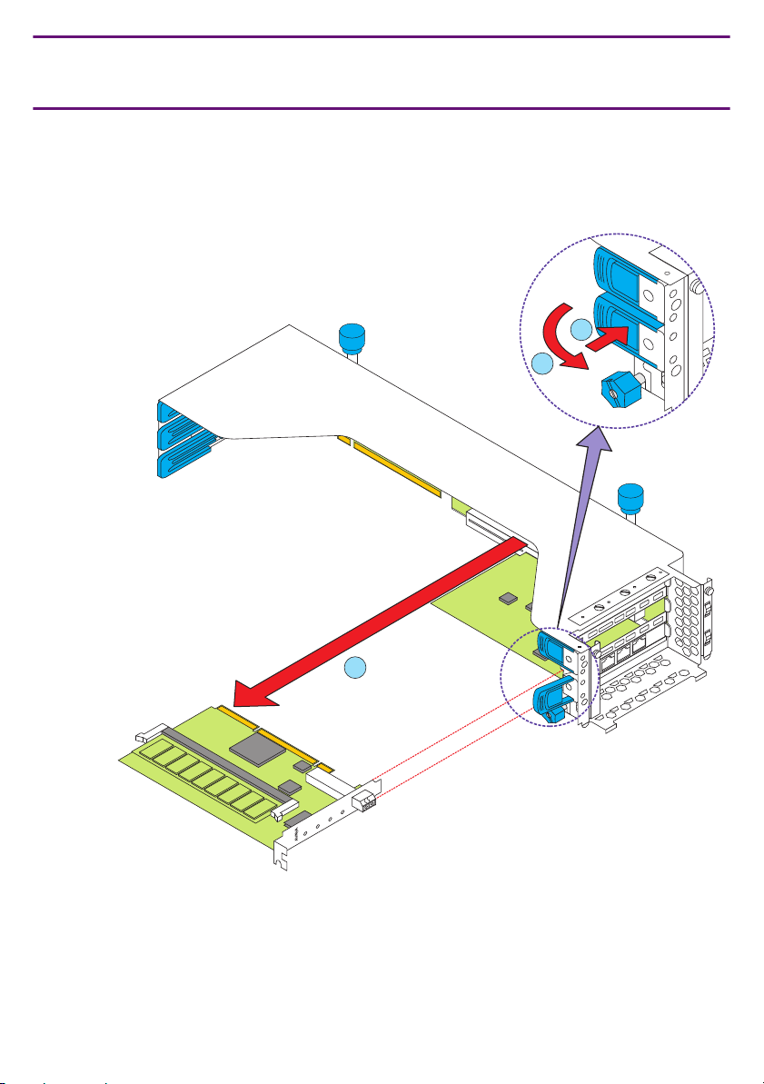
4c Installing the DAL2 Card: Removing the DAL1 Card
(S8710/ S8720)
Note:
Note: Communication Manager 5.0 requires removing the DAL1 card and
replacing it with the DAL2 card.
1
2
3
MEMORY
DUP
DAL1
ACTIVE
LINC
SYNC
LINC
MODE
TRANS
MODE
RECEIVE
10 Quick Start for Hardware Installation: Avaya S8700-Series Servers
8710qsd1 LAO 083007
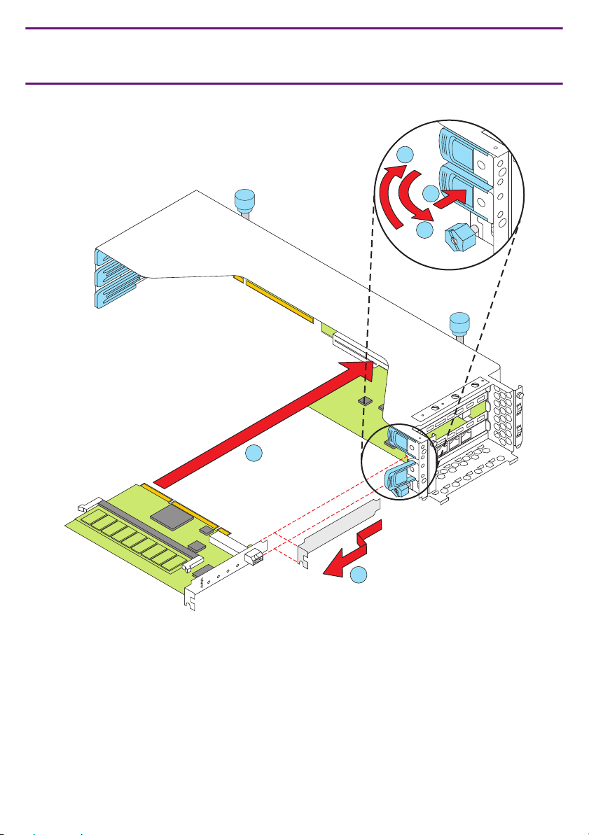
4d Installing the DAL2 Card: Inserting the DAL2 Card
(S8720/S8710)
5
1
2
4
MEMORY
DUP
DAL1
ACTIVE
LINC
SYNC
LINC
MODE
TRANS
MODE
RECEIVE
3
8720qsxc LAO 101206
Issue 8 January 2008 11
 Loading...