

Page 1

,QVWDOOLQJDQG&RQILJXULQJWKH
$YD\D6RU60HGLD
6HUYHU
03-300145
Issue 1
June 2004
Page 2

Copyright 2004, Avaya Inc.
All Rights Reserved
Notice
Every effort was made to ensur e that the in forma tion in this do cume nt
was complete and accurate at the time of printing. However,
information is subject to change.
Warranty
Avaya Inc. provides a limited warranty on this product. Refer to your
sales agreement to establish the terms of the limited warranty. In
addition, Avaya’s standard warranty language as well as information
regarding support for this product, while under warranty, is available
through the following Web site: http://www.avaya.com/support
Preventing Toll Fraud
“Toll fraud” is the unauthorized use of your telecommunications
system by an unauthorized party (for example, a person who is not a
corporate employee, agent, subcontracto r, or is not working on your
company's behalf). Be aw a re t h at the re ma y be a risk of toll fraud
associated with your system and that, if toll fraud occurs, it can result
in substantial additional charges for your telecommunications
services.
Avaya Fraud Intervention
If you suspect that you are being victimized by toll fraud and you need
technical assistance or support, in the United States and Canada, call
the Technical Service Center's Toll Fraud Intervention Hotline at
1-800-643-2353.
Disclaimer
Avaya is not responsible for any modifications, additions or deletions
to the original published versi on of this documentation unless such
modifications, additions or de leti ons w e re pe rformed by Avaya.
Customer and/or End User agree to indemnify and hold harmle ss
Avaya, Avaya's agents, servants and employees against all claims,
lawsuits, demands and judgments arising out of, or in connection with,
subsequent modifications, additions or deletions to this documentation
to the extent made by the Custome r or End User.
How to Get Help
For additional support telephone numbers, go to the Avaya support
Web site: http://www.avaya.com/support
• Within the United States, click the Escalation Management link.
Then click the approp ria t e li nk for the type of support you need.
• Outside the Unit ed States, click th e Escalation Management link.
Then click the International Services link that includes telephone
numbers for the internationa l Centers of Excellence.
Providing Telecommunications Security
Telecommunications security (of voice, data, and/or video
communications) is the prevention of any type of intrusion to (that is,
either unauthorized or m al ic io us access to or use of) your company's
telecommunications equipment by some party.
Your company's “t elecommunicatio n s equipment” includes both this
Avaya product and any other voice/data/video equipment that could be
accessed via this Avaya product (that is, “networked equipment”).
An “outside party” is an yone who is not a corporate employee, agent,
subcontractor, or is not working on your company's behalf. Whereas, a
“malicious party” is anyone (in cl udi ng someone who may be
otherwise authorized) who accesses your telecommunications
equipment with eit her malicious or mischievous i n te nt .
. If you are:
.
Such intrusions may be either to/throu gh synchronous (timemultiplexed and/or circ uit-based), or asynchronous (character-,
message-, or packet-based) equipment, or interfaces for reasons of:
• Utilization (of capabilities special to the accessed equipment)
• Theft (such as, of intellec t ual property, financial assets, or toll
facility access)
• Eavesdropping (privacy invasions to humans)
• Mischief (troubling, but apparently innocuous, tampering)
• Harm (such as harmful tampering , da ta loss or alteration,
regardless of motive or intent)
Be aware that there may be a ri sk of unauthorized intrusions
associated with your syste m a nd/ or it s net w orked equipment. Also
realize tha t, if such an intru s ion should occ u r, it could result in a
variety of losses to your company (including but not limit ed to,
human/data privacy, intellectual property, material assets, financial
resources, labor costs, and/or legal costs).
Responsibility for Your Company’s Telecommunications Security
The final responsibility for securi ng both this system and its
networked equipmen t re sts wit h you - Avaya’s customer system
administrator, your telecommunications pe e rs, a nd your managers.
Base the fulfillment of your responsibility on acquired knowledge and
resources from a variety of sources incl udi ng but not limited to:
• Installation docu ments
• System administration documents
• Security documents
• Hardware-/so ft w ar e-based security t ool s
• Shared information between you and your peers
• Telecommunications security experts
To prevent intrusions to your telecommunications equipment, you and
your peers should carefully pro gra m a nd c onfi gure:
• Your Avaya-provided telecommunications systems and their
interfaces
• Your Avaya-provided software applications, as well as their
underlying hardw ar e/software platforms an d int erfaces
• Any other equipment networked to your Avaya products
TCP/IP Facilities
Customers may experience difference s in product performance,
reliability and security depending upon network configurations/design
and topologies, even when the product performs as warranted.
Standards Compliance
Avaya Inc. is not responsible for any radio or television interference
caused by unauthorize d modifications of this equipment or the
substitution or attachment of connecting cables and equipment othe r
than those specified by Avaya Inc. The correction of interference
caused by such unauth orized mo dificati ons, subs tituti on or atta chment
will be the responsi bili ty o f the u ser. Pursuan t to Part 15 of the Federal
Communications Commission (FCC) Rules, the user is cautioned that
changes or modifications not expressly approved by Avaya Inc. could
void the user’s authority to operate this equipment.
Product Safety Standards
This product complies with and conforms to the following
international Product Safety standards as applicable:
Safety of Information Technology Equipment , IEC 60950, 3rd
Edition, or IEC 60950-1 , 1st Edi ti on, including all relevant na tional
deviations as listed in Compliance with IEC for Electrical Equipment
(IECEE) CB-96A.
Safety of Information Technology Equipment , CAN/CSA-C22.2
No. 60950-00 / UL 60950, 3rd Edition, or CAN/CSA-C22.2 No .
60950-1-03 / UL 60950-1.
Safety Requirements for Custom e r Equipment, ACA Technical
Standard (TS) 001 - 1997.
Page 3

One or more of the following Mexican national standards, as
applicable: NOM 001 SCFI 19 93, N O M SCFI 016 1993, NOM 019
SCFI 1998.
The equipment described in this document may contain Class 1
LASER Device(s). These devices comply with the following
standards:
• EN 60825-1, Edition 1. 1, 1998-01
• 21 CFR 1040.10 and CFR 1040.11.
The LASER devices used in Avaya equipment typically operate within
the following parameters :
Typical Center Wavelength Maximum Output Power
830 nm - 860 nm -1.5 dBm
1270 nm - 1360 nm -3.0 dBm
1540 nm - 1570 nm 5.0 dBm
Luokan 1 Laserlaite
Klass 1 Laser Apparat
Use of controls or adjustmen ts or pe rformance of procedures oth er
than those specified herein may result in hazardous radiation
exposures. Contact your Avaya representative for more laser product
information.
Electromagnetic Compatibility (EM C ) Standards
This product complies w it h and conforms to the following
international EMC standa rds and all relevant national deviati ons:
Limits and Methods of Measurement of Radio Interference of
Information Technology Equipment, CISPR 22: 1997 and
EN55022:1998.
Information Technology Equipment – Immunity Cha ra ct er istic s –
Limits and Methods of Measurement, CISPR 24:1997 and
EN55024:1998, including:
• Electrostatic Discharge (ESD) IEC 61 000-4-2
• Radiated Immunity IEC 61000-4-3
• Electrical Fast Transient IEC 61000-4-4
• Lightning Effects IEC 61000-4-5
• Conducted Immunity IE C 61000-4-6
• Mains Frequency Magnetic Field IEC 61000-4-8
• Voltage Dips and Variations IEC 61000-4-11
Power Line Emissions, IEC 61000-3-2: Electromagnetic compatibility
(EMC) – Part 3-2: Limits – Limits for harmonic current emissions.
Power Line Emissions, IEC 61000-3-3: Electromagnetic compatibility
(EMC) – Part 3-3: Limits – Limitation of voltage changes, voltage
fluctuations and flicker in public low-voltage suppl y system s.
Federal Communications Commission Statement
Part 15:
Note: This equipment has been tested and found to comply with
the limits for a Class A digital device, pursuant to Part 15 of the
FCC Rules. The s e limits are designed to provide reasonable
protection against h a r m ful interference when the equipment is
operated in a commercial environment. This equipment generates,
uses, and can radiate radio frequency energy and, if not installed
and used in accordance with the instruction manual, may cause
harmful interferenc e to radio communications . Op eration of this
equipment in a residential area is likely to cause harmful
interference in w h ic h case the user will be req u ired to c o rrect the
interference at his own expense.
Part 68: Answer-Supervision Signaling
Allowing this equipm ent to be operated in a man ner that does not
provide proper answer-supervision sig na ling is in violation of Part 68
rules. This equipment returns answer-supervision signals to the public
switched network when:
• answered by the called station,
• answered by the attendant, or
• routed to a recorde d an n ou ncement that can be admin i stered by
the customer premises equipment (CPE) user.
This equipment returns an sw er-supervision signals on all direct
inward dialed (DID) ca lls fo rwarded back to the public switched
telephone network. Permissi bl e exceptions are:
• A call is unanswered.
• A busy tone is received.
• A reorder tone is receive d .
Avaya attests that this registered equipment is capabl e of providing
users access to int erstate providers of operato r services th rough the us e
of access codes. Modification of this equipment by call aggregators to
block access dialing codes is a violation of the Telephone Operator
Consumers Act of 1990.
REN Number
For MCC1, SCC1, CMC1, G600, and G 650 M e d ia Gat eways:
This equipment complie s with Part 68 of the FCC rules. On either the
rear or inside the front cover of this equipment is a label that contains,
among other information, the FCC registration number, and ringer
equivalence numb er (R EN ) for this equipment. If requested, this
information must be provided to the telephone company.
For G350 and G700 Media Gateways:
This equipment complie s with Part 68 of th e F C C rules and the
requirements adopted by the ACTA. On the rear of this equipment is a
label that contains, among other information, a product i de nti fi er in
the format US:AAAEQ##TXXXX. The digits represented by ## are
the ringer equivalence number (REN) without a decim al p oin t (fo r
example, 03 is a REN of 0.3). If requested, this number must be
provided to the tel ephone company.
For all media gateways:
The REN is used to determine the qua ntity of devices that may be
connected to the telephone line. Excessive RENs on the telephone line
may result in devices not ringing in response to an incoming call. In
most, but not all areas, the sum of RE Ns should not exceed 5.0. To be
certain of the num ber of devices that may be connected to a line, as
determined by the total RENs, contact the local telephone company.
REN is not required for some t ype s of ana l og or digital facilities.
Means of Connection
Connection of this equipment to the telephone network is shown in the
following tables.
For MCC1, SCC1, CMC1, G600, and G 650 M e d ia Gat eways:
Manufacturer’s Port
Identifier
FIC Code SOC/REN/
A.S. Code
Network
Jacks
Off premises station OL13C 9.0F RJ2GX,
RJ21X,
RJ11C
DID trunk 02RV2-T 0.0B RJ2GX,
RJ21X
CO trunk 02GS2 0.3A RJ21X
02LS2 0.3A RJ21X
Tie trunk TL3 1M 9.0F RJ2G X
Basic Rate Int e r face 0 2I S 5 6.0F, 6.0Y RJ49C
1.544 digital interface 04DU9-BN 6.0F RJ48C,
RJ48M
04DU9-IKN 6.0F RJ48C,
RJ48M
04DU9-ISN 6.0F RJ48C,
RJ48M
120A4 channel servic e unit 04DU9-DN 6. 0Y RJ48C
Page 4

For G350 and G700 Media G ate w ays:
Manufactur er’s Port
Identifier
Ground Start CO trunk 02GS2 1.0A RJ11C
DID trunk 02RV2-T AS.0 RJ11C
Loop Start CO trunk 02LS2 0.5A RJ11C
1.544 digital interface 04DU9-BN 6.0Y RJ48C
Basic Rate Interface 02IS5 6.0F RJ49C
For all media gateways:
If the terminal equipment (for examp le , the media server or me dia
gateway) causes harm to the tel e phone network, the telephone
company will notify you in advance that temporar y di scontinuance of
service may be require d. But if advance notice is not practical, the
telephone company will notify the customer as soon as possible. Also,
you will be advised of your right to file a complaint with the FCC if
you believe it is necessary.
The telephone company may make changes in its facilities, equipment,
operations or procedures tha t co uld affect the operation of the
equipment. If this hap p e ns, t he telephone company will provide
advance notice in order for you to ma ke nec essa ry m odifications to
maintain uninterrupted service.
If trouble is experienced w i th t his equipment, for repair or warrant y
information, plea s e contact the Technical Service Center at
1-800-242- 2121 or contact your local Avaya representative. If the
equipment is causing ha rm to the telephone network, the telephone
company may request tha t you disconnect the equipment until the
problem is re s olved.
A plug and jack used to connect this equipment to the premises wiring
and telephone network must comply with the applicable FCC Part 68
rules and requirements adopted by the ACTA. A compliant telephone
cord and modular plug is provided with this product . It is designed to
be connected to a co mp atible modular jack th at is also compliant . I t is
recommended that repairs be performed by Avaya certified
technicians.
The equipment cannot be use d on public coin phone service provided
by the telephone com pany. Connection to party line service is subject
to state tariffs. Contact the state public utility commission, public
service commission or corporation commission for information.
This equipmen t, if it uses a telephone receiver, is hearing aid
compatible.
Canadian Department of Communications (DOC) Interfe rence
Information
This Class A digital appar at us complies with Canadian ICE S -003.
Cet appareil numérique de la classe A est conforme à la norme
NMB-003 du Canada.
This equipment meets t he applicable Industry Canada Terminal
Equipment Technical Specifications. This is confirmed by the
registration number. The abbreviation, IC, be fore the registration
number signifies that registration was perform e d based on a
Declaration of Conformi ty i ndicating that Industry Canada tec hni cal
specifications were met. It does not imply that Industry Canada
approved the equipment.
Installation and Repairs
Before installing this equipment, users should ensure that it is
permissible to be connected to the facilities of the local
telecommunications company. The equipment must also be installed
using an acceptable method of connection. The customer shou ld be
aware that compliance with the above conditions may not prevent
degradation of service in some situations.
FIC Code SOC/REN/
A.S. Code
04DU9-DN 6.0Y RJ48C
04DU9-IKN 6.0Y RJ48C
04DU9-ISN 6.0Y RJ48C
Network
Jacks
Repairs to certified equipment should be coordinated by a
representative designated by the suppl ier. Any repairs or alterations
made by the user to this equipment, or equipment malfunctions, may
give the telecommunicat ions company cause to request the use r to
disconnect the equip me nt.
Declarations of Conformity
United States FCC Part 68 Supplier ’s Declaration of Conform ity
(SDoC)
Avaya Inc. in the United States of America hereby certifies that th e
equipment describe d in thi s document and bearing a TIA TS B-168
label identi f ication number complies with the FCC’s Rules and
Regulations 47 CFR Part 68, an d the A dm inistrative Council on
Terminal Attachments (ACTA) adopted technical criteria.
Avaya further asserts that Avaya handset-equipped terminal
equipment described in this document complies wi th Pa ragraph
68.316 of the FCC Rules and Regu lati ons de fi ning Hearing Aid
Compatibil ity and is deeme d compatible with hearing aids.
Copies of SDoCs signed by the Responsible Par ty in the U. S. ca n be
obtained by contacting your local sales representative a nd a re
available on the following Web site: http://www.avaya.com/support
All A vay a me dia s erv ers an d me dia ga te way s are compl ia nt wi th FCC
Part 68, but many have been registered with the FCC before the SDoC
process was available. A list of all Avaya registered products may be
found at: http://www.part68.org
as manufacturer.
European Union Declarations of Conformity
Avaya Inc. declares that the equipment spec ified in this docum ent
bearing the “CE” (Conformité Europeénne) mark conforms to the
European Union Radio and Telecommunications Terminal Equipment
Directive (1999/5/EC), including the Electromagnetic Compatibility
Directive (89/336/EEC) and Low Voltage Directive (73/23/EEC) .
Copies of these Declarations of Conformity (DoCs) can be obtained
by contacting your local sale s representative and are avai la bl e on the
following Web site: http://www.avaya.com/support
Japan
This is a Class A product based on the standard of the Voluntary
Control Council for Interfe rence by Information Technology
Equipmen t ( V CCI). If this equipment is us ed in a domestic
environment, radio disturbance may occur, in which case, the user
may be required to take co rrective actions.
To order copies of this and other documents:
Call: Avaya Publications Center
Voice 1.800.457.1235 or 1.207.866.6701
FAX 1.800.457.1764 or 1.207.626.7269
Write: Globalware Solutio ns
200 Ward Hill Avenue
Haverhill, MA 01835 USA
Attention: Avaya Account Management
E-mail: totalware@gwsmail.com
For the most current versions of documentation, go to the Avaya
support Web site: http://www.avaya.com/support
by conducting a search using “Avaya”
.
.
.
Page 5

Contents
About This Documentation 9
• Audience 9
• Using this documentation 9
• Conventions 10
General 10
Physical dimensions 10
Terminology 10
Typography 10
Commands 11
Keys 11
User input 11
System output and field names 12
Contents
• Downloading this book and updates from the Web 12
Downloading this documentation 12
• Safety labels and security alert labels 13
• Related resources 13
• Technical assistance 14
Within the US 14
International 14
• Trademarks 14
• Sending us comments 14
1 Introduction 15
• Pre-installation information 16
Before you go on site 16
Downloading license and Avaya authentication files 17
Copying files to the laptop 17
Before you start the installation 18
• Equipment specifications 18
• Required hardware 20
• Documentation 21
• Connecting to the customer’s network 22
Installing and Configuring the Avaya S8700 or S8710 Media Server 5
June 2004
Page 6

Contents
• Connecting the USB modems 24
Connecting to collocated servers 24
Connecting to separated servers 24
• High level overview of installation process 25
Installing and cabling the media server complex 25
Installing Avaya Communication Manager 25
Configuring the media server 25
Translating the IPSIs 25
Installing and cabling the media gateways 25
Completing the installation administration 26
Testing the complete installation 26
2 Configuring the hardware in the rack 27
• Configuring the SNMP modules in the UPS 28
Single control network 30
Duplicated control network 30
Setting selected traps (alarming) 30
• Configuring the SNMP subagent in the Avaya Ethernet switch (if used) 31
• Configuring the media server 33
Clearing the ARP cache on the laptop 33
Powering up the media server 34
Accessing the media server 34
Setting up Telnet 34
Installing Avaya Communication Manager 35
Using the Installation Wizard 36
Verifying media server connection to the customer’s LAN (if provided) 38
Configuring the modem 39
Testing the media server LEDs 40
Disconnecting from the media server 40
• Configuring second media server 41
3 Translating the IPSIs 43
• Starting terminal emulation 43
• Inputing translation s 44
• Resetting the media server 44
• Adding media gateways 44
• Administering the IPSIs 45
Adding IPSI information 45
6 Installing and Configuring the Avaya S8700 or S8710 Media Server
June 2004
Page 7

Enabling IPSI duplication (duplicated control network only) 47
Setting alarm activation level 48
Installing the translation file 48
4 Connecting to the IPSIs 49
• Programming the IPSI circuit packs 50
Using DHCP addressing 50
Using static addressing 51
• Verifying that IPSIs are translated 54
• Verifying connectivity to media server 55
• Upgrading IPSI firmware version (if necessary) 55
• Enabling control of IPSIs 55
• Verifying license status 56
• Reusing a TN2312AP/BP circuit pack 56
Contents
5 Completing the installation administration 57
• Verifying translations 57
• Setting daylight savings time rules 58
• Setting locations (if necessary) 59
• Verifying date and time 59
• Resolving alarms 60
• Enabling and disabling Ethernet switch ports 60
• Backing up files to the compact flash media (S8710 only) 61
• Backing up files to the PCMCIA flashcard (S8700 only) 63
• Telneting to media server 65
• Enabling alarms 65
To INADS via modem 65
To INADS via SNMP 65
To INADS on second server 65
• Registering the system 66
6 Installing the media gateways 67
7 Testing the media server installation 69
• Testing the TN2312BP IPSI circuit pack 69
• Testing the license file 70
Installing and Configuring the Avaya S8700 or S8710 Media Server 7
June 2004
Page 8

Contents
• LED indicators 71
S8700 Media Server LEDs 71
Testing the media server LEDs 72
Interpreting the test results 73
LEDs on the back of the media server 73
S8710 Media Server LEDs 74
Avaya Ethernet switch LEDs 76
Uninterruptible power supply LEDs 77
IPSI LEDs 77
A Accessing the media server 81
• Connecting to the media server directly 81
• Connecting to the media server
remotely over the network 84
• Connecting to the media server
remotely over a modem 84
Setting up a dial-up connection 84
Dialing up to the media server 85
Finding the active media server IP address 85
• Accessing the Maintenance Web Interface 85
• Using the command line interface 86
•Logins 86
• Network configuration 87
• Browser settings 88
Connecting directly to the media server 88
Connecting remotely through the netwo r k 88
B Troubleshooting an installation 89
• Installing the media server hardware 89
• Configuring the media server hardware 90
• Installing the license and Avaya authentication files 91
Index 93
8 Installing and Configuring the Avaya S8700 or S8710 Media Server
June 2004
Page 9

About This Documentation
This documentation, Inst all i ng and Con f igur i ng the Avaya S8700 or S8710 Media Server (03-300145),
provides procedures for installing Avaya Communication Manager on and configuring an S8700 or
S8710 Media Server and other control network components.
Audience
This documentation is for the following people tasked with installing and configuring the media server
components:
• Trained field installation and maintenance personnel
• Technical support personnel
• Authorized Business Par tn ers
About This Documentation
Audience
Using this documentation
Use this documentation as a guide to install and configure the S8700 or S8710 Media Server. For
information about a p artic ular tas k, use t he ind ex or table o f contents to locate the pa ge numb er where the
information is described.
For an overview of the installation process, see High level overview of installation process on page 25
Read the Pre-installation information on page 16
completed before beginnin g the pro cedu res described in this document. One s tep you norm a lly comp lete
before going to the customer site is getting the license and Avaya authentication files from the Remote
Feature Activation (RFA) Web site.
For technical specifications on the hardware, see Table 2, Avaya S8710 Media Server features and
specifications, on page 19.
For the physical installation and cabling of the hardware, see the Quick Start for Hardwar e Installation:
Avaya S8700 or S8710 Media Server (555-245-703). Use the remaining sections of the document in the
sequence they are presented. If certain components are not to be installed, skip the procedures for those
components. You install and configure the media server components using information in the following
sections:
• Configuring the SNMP modules in the UPS on page 28
• Configuring the SNMP subagent in the Avaya Ethernet switch (if used) on page 31
• Configuring the media server on page 33
.
first. This section lists all the tasks that must be
• Configuring second media server on page 41
• Translating the IPSIs on page 43
Installing and Configuring the Avaya S8700 or S8710 Media Server 9
June 2004
Page 10

About This Documentation
Conventions
T o complete the installation, you install the media gateways, using sections in Installing the Avaya G650
Media Gateway (03-300144).
Connect the system to the customer’s network using information in Connecting to the IPSIs
Complete the installation using information in the f ollowing sections:
• Completing the installation administration on page 57
• Testing the media server installation on page 69
• Accessing the media server on page 81
If problems occur during the installation, use Troubleshooting an installation
them.
Conventions
This section describes the conventions that we use in this book.
General
We show commands and screens from the newest Avaya Communication Manager and refer to the most
current documentation.
on page 49.
on page 89 to try to resolve
Physical dimensions
All physical dimensions are in English units followed by metric units in parentheses. Wire gauge
measurements are in AWG followed by the diameter in millimeters in parentheses.
Terminology
We use the following terminology in this documentation:
• Configuration is a general term that encompasses all references to an Avaya media server with
media gateways running Avaya Communication Manager.
• Cabinet refers to a stack of medi a gateways (such as the G650) that are TDM-cabled togethe r . It is
the same as a port network. It can also refer to the MCC1 (multi-carrier cabinet).
• UUCSS refers to a circuit pack address in cabinet-carrier-slot order.
Typography
This section describes the typographical conventions fo r co mmand s, keys, user input, system output, and
field names.
10 Installing and Configuring the Avaya S8700 or S8710 Media Server
June 2004
Page 11

Commands
Commands are in bold sans serif type.
Example
Type
change-switch-time-zone and press Enter.
About This Documentation
Conventions
Command variables are in
Example
Type
change machine machine_name, where machine_name is the name of the call delivery
machine.
Command options are in
Example
Type
copybcf [-F34].
bold sans serif italic type.
bold sans serif type inside square brackets.
Keys
The names of keys are in bold type.
Example
Use the Down Arrow key to scroll through the fields.
When you must press and hold a key and then press a second or third key, we separate the names of the
keys are separated with a plus sign (+).
Example
Press ALT+D.
When you must press two or more keys in seq uence, we separ ate the names of the k eys are separate d with
a space.
Example
Press Escape J.
When you must press a function key, we provide the function of the key in parentheses after the name of
the key.
Example
Press F3 (Save).
User input
User input is in bold type, whether you must type the input, select the in put f rom a menu, or clic k a
button or similar element on a screen or a Web page.
Examples
• Type exit, and then press Enter.
• On the File menu, click Save.
• On the Network Gateway page, click Configure > Hardware.
Installing and Configuring the Avaya S8700 or S8710 Media Server 11
June 2004
Page 12

About This Documentation
Downloading this book and updates from the Web
System output and field names
System output on the screen is in monospaced typ e .
Example
• The system displays the following message:
The installation is in progress.
Field names on the screen are in bold sans ser if type.
Example
• Type y in the Message Transfer? field.
Downloading this book and updates from the Web
You can download the latest version of this document from the Avaya Support Web site
(http://support.avaya.com
your personal computer.
). You must have access to the Inter net and a copy of Adobe Reader ins talled on
Avaya makes every effort to ensure that the information in this book is complete and accurate. However,
information can change after we publish this documentation. Therefore, the Avaya Support Web site
might also contain new product information and updates to the information in this book. You can also
download these updates from the Avaya Support Web site.
Downloading this documentation
To download the latest version of this documentation:
1 Access the Avaya Support Web site at http://support.avaya.com.
2 Type the documentation number in the Search Support box in the upper left and click Go.
The system displays the Product Documentation Search Results page.
3 Or click Product Documentation.
4 From the menu on the left, select Communications Systems.
5 Scroll down to find the product and latest release number.
6 Click the release number to view the list of titles.
7 Click on the title that you want.
8 Click one of the following options:
• PDF Format to download the book in regular PDF format
• ZIP Format to download the book in zipped PDF format
12 Installing and Configuring the Avaya S8700 or S8710 Media Server
June 2004
Page 13

Safety labels and security alert labels
Observe all caution, warning, and danger statements to help prevent loss of service, equipment damage,
personal injury, and security problems. This documentation uses the following safety labels and security
alert labels:
CAUTION:
A caution statement calls attention to a situation that can result in harm to software, loss of
data, or an interruption in service.
!
WARNING:
A warning statement calls attention to a situation that can result in harm to hardware or equipment,
including ESD damage to electronic components.
!
DANGER:
A danger statement calls attention to a situation that can result in harm to personnel.
About This Documentation
Safety labels and security alert labels
!
SECURITY ALERT:
A security alert calls attention to a situation that can increase the potential for
unauthorized access to a media server or use of a telecommunications system.
Related resources
For providing physical installation and connection information, see Quick Start for Hardware
Installation: Avaya S8700 or S8710 Media Server (555-245-703).
Additional information on installing some adjunct and peripheral equipment that the media server
supports is contained in Adding New Hardware—S8500, S8700, and S8710 Media Servers (555-233-
112).
For all documents associated with the S8700 or S8710 Media Server, including those described above,
see Documentation fo r Avaya Communication Manaager, Media Gateways and Servers CD ( 03-300151).
Installing and Configuring the Avaya S8700 or S8710 Media Server 13
June 2004
Page 14

About This Documentation
Technical assistance
Technical assistance
Avaya provides the following resources for technical assistance.
Within the US
For help with:
• Feature administration and system applications, call the Avaya Helpline at
1-800-225-7585
• Maintenance and repair, call the Avaya National Customer Care Support Line at
1-800-242-2121
• Toll fraud, call Avaya Toll Fraud Intervention at 1-800-643-2353
International
For all international resources, contact your local Avaya authorized dealer for additional help.
Trademarks
All trademarks identified by the ® or TM are registered trademarks or trademarks, respectively, of Avaya
Inc. All other trademarks are the property of their respective owners.
Sending us comments
Avaya welcomes your comments about this book. To reach us by
• Mail, send your comments to
Avaya Inc.
Product Documentation Group
Room B3-H13
1300 W. 120 Ave.
Westminster, CO 80234 USA
• E-mail, send your comments to:
document@avaya.com
• Fax, send your comments to:
1-303-538-1741
Make sure that you mention the name and number of this book, Installing and Configuring the Avaya
S8700 or S8710 Media Server (03-300145).
14 Installing and Configuring the Avaya S8700 or S8710 Media Server
June 2004
Page 15

1 Introduction
These procedures are for installing Avaya Communication Manager and configuring a new Av aya S8700
or S8710 Media Server and associated components in either a Multi-Connect or an IP-Connect
configuration. The installation procedures for both models are basically the same; where they differ is
noted.
As part of the procedures for configuring the various pieces of hardware, you use two administration
interfaces: the Maintenance Web Interface and a command line interface using either telnet or a terminal
emulation program such as Avaya Native Configuration Manager. You also use the Avaya Installation
Wizard to configure the media servers.
There are no requirements to install the media servers before the media gateways; however, the license
file only allows 30 minutes to "see" the administered and connected IP Server Interface circuit packs.
The following information is included in this installation procedure:
• Pre-installation information on page 16
1Introduction
— Equipment specifications on page 18
— Required hardware
on page 20
• Connecting to the customer’s network on page 22
• Connecting the USB modems on page 24
• High level overview of installation process on page 25
• Configuring the hardware in the rack on page 27
— Configuring the SNMP modules in the UPS on page 28
— Configuring the SNMP subagent in the Avaya Ethernet switch (if used) on page 31
— Configuring the media server on page 33
— Configuring second media server
on page 41
• Translating the IPSIs on page 43
• Connecting to the IPSIs on page 49
• Completing the installation administration on page 57
• Installing the media gateways on page 67
• Testing the media server installation on page 69
• Accessing the media server on page 81
• Troubleshooting an installation on page 89
Installing and Configuring the Avaya S8700 or S8710 Media Server 15
June 2004
Page 16

1 Introduction
Pre-installation information
Pre-installation information
Before you go on site
Before going on site, make sure the customer has a local area network set up and running and a network
administrator available the day of the installation. Before beginning the software installatio n and media
server configuration, make sure you have the filled-out Electronic Preinstallation Worksheet (EPW) on
the services laptop. See the Avaya Installation Wizard Web site (http://support.avaya.com/avayaiw
the blank form.
In addition, the pre-installation team should have done the following tasks. If they were not all done, do
not continue with the installation.
• Verify that the s ervices laptop has the right hardware and software. See Connecting to the media
server directly on page 81 for the list of computer hardware and software specifications.
• Verify that you have current translations av ailabl e for downl oad vi a ProVision.
• Verify that you have a filled-out Electronic Preinstallation Worksheet (EPW). The EPW provides
— IP addresses
) for
—Product ID
— Avaya services telephone number for remote access over modem
— Avaya services IP address for alarms through the network
• Verify that you have the current software update (patch), if required, and license and Avaya
authentication files on your services laptop.
• Verify that you have the current firmware available. Firmware for the IPSIs, C-LAN, MedPro,
and VAL circuit packs are on the software CD, but check the A vaya Suppo rt Web site
(http://support.avaya.com
firmware.
), Download Software and Firmware, for the latest software and
• Verify that you have all the login IDs and passwords to acces s the S87 00 or S8710 Media Servers
and server complex components. This includes the unique service password for that customer’s
equipment.
T o obtain the password for a specific media server, call ASG Conversant (1.800.248.1234 or
1.720.444.5557). You must have the IL, FL, or product ID to get the password.
To log in through the services port as craft after you install the Avaya authentication file, use this
password, which does not require an ASG challenge or response.
16 Installing and Configuring the Avaya S8700 or S8710 Media Server
June 2004
Page 17

Pre-installation info rma tio n
Downloading license and Avaya authentication files
Use the Remote Feature Activation (RFA) to obtain the license and Avaya authentication files. RFA is a
W eb -based application, av ailable to Avaya employees and authorized Business Partners, that enables you
to create and deploy license files for all product platforms. The RFA Web site is at http://rfa.avaya.com
For specific information on RFA and how to generate license and A v aya authentication files, go to the the
RFA Information page available on the RFA Web site.
.
NOTE:
T o access the RFA application, you must take the RFA online training and pass the online
test.
To generate a license file, you need the following information:
• Your personal Sin gle Sign-On (SSO) for the RFA Web site authentication login.
• SAP order number
• Required customer information
• Serial number of one TN2312BP Inter net Protocol Server Interface (I PSI) circuit pack d esignated
the reference IPSI.
1Introduction
• Intranet access to the RFA Web page with Internet Explorer 5.0 or higher.
Before arriving on site, download the license and Avaya authentication files to the services laptop. The
license and Avaya authentication files are installed during the installation process.
Once the A v aya authentication files are installed, A vaya ser vices logins to the media server are protected
by a challenge/response system called Access Security Gateway (ASG). The ASG challenge/response
protocol confirms the validity of each user, reducing the opportunity for unauthorized access.
When finished installing the Avaya authentication file, Avaya Communication Manager has a password
for the craft login. This password is unique to the customer’s server. You can use the password the next
time you log in as craft, provided you access the media server throug h the ser vices port. You do not need
an ASG challenge/response to log in this way, even though every other means of craft access still require
an ASG challenge/response. The revised password is recorded by RFA and is obtained from ASG
Conversant at 1-800-248-1234 or 1-720-444-5557.
Copying files to the laptop
In addition to the license and Avaya authentication files, you must copy o ther required files to the l apt op .
This includes, the filled-out Electronic Preinstallation Wo rksheet (EPW); any software updates; current
firmware, and ART script.
To get a filled-out EPW, go to the project manager or customer. To get a blank EPW, go to the Avaya
Installation Wizard Web site (http://support.avaya.com/avayaiw
). Have the customer fill it out.
To get the software update (patch), go to the Avaya Support Web site (http://avaya.com/support
select Software & Firmware Downloads to identify and copy the required software update.
To get the latest firmware for the programmable circuit packs, go to the Avaya Support Web site at
http://avaya.com/support
firmware.
Installing and Configuring the Avaya S8700 or S8710 Media Server 17
June 2004
and select Software & Firmware Downloads to identify and copy the latest
) and
Page 18

1 Introduction
Equipment specifications
Before you start the installation
The pre-installation team should have don e the fo llowing t asks. If they were not all done, d o not con tinue
with the installation.
• Verify that the ope n, customer-s upplied, EIA-310D (or equ ivalent) standard 19-inch (48-
centimeter) equipment racks are properly ins talled and s olidly secured . Mak e s ure that the sc rews
that come with the racks are there. The S8700 Media Server requires a 2-post rack. The S8710
Media Server requires a 4-post rack . If us ing a rack cabinet, make sure it has adequate v entilation.
• Verify that the rail kit to support the S8710 Media Serv er are available fo r installation.
• Verify that the rail kits, required to suppor t the ver y heavy UPSs, are installed on the rack or
available for installation. For information on installing the rails, refer to the docu mentation that
comes with the rail kits.
• Verify that the equipment rack(s) is(are) grounded per local code. See Job Ai d: Appr o ved Gr ounds
(555-245-772).
• Verify that the customer provides AC power to the rack from a nonswitched outlet.
• Verify that cabling for the TN2312BP Internet Protocol Server Interface (IPSI) circuit packs is
labeled and run from the control hardware rack to the port networks or that appropriate
connectivity is provided.
• Verify that you have all the equipment on site. See T abl e 3, Lis t of r equi red hard w are, on page 2 0
for the list of required hardware.
Equipment specifications
The media server control network components consist of two media servers, one or two Ethernet
switch(es), and two UPSs. See Table 1, Control network components specifications,
Table 1: Control network components specifications
Dimensions
Component
Media Server
S8700
S8710
Ethernet Switch:
P133G2/P134G2
P333T/334T
UPS:
700 VA
1500 VA
3.5h x 17d x 17w
3.4h x 26d x 17.5w
3.5h x 14d x 19w
3.5h x 18d x 19w
3.5h x 19d x 17w
3.5h x 24d x 17w
9h x 43d x 43w
8.6h x 66d x 45w22
9h x 35d x 48w
9h x 45d x 48w
9h x 48d x 43w
9h x 30d x 43w
on page 18.
Weight (lb/kg)English (in.) Metric (cm) Us (height in rack)
25/11
60/27
2
2
2
2
11,13/5,6
16.5/7.5
34/15
50/23
The internal room temperature must not exceed 104° F (40° C).
18 Installing and Configuring the Avaya S8700 or S8710 Media Server
June 2004
Page 19

Equipment specifications
1Introduction
Table 2, Avaya S8710 Media Server features and specifications,
on page 19 outlines the fe atures and
specifications of the Avaya S8710 Media Server.
NOTE:
Some values are shown at maximum configuration. Avaya values are slightly lower then
the maximum.
.
T able 2: Avaya S8710 Media Server features and specifications 1 of 2
Feature Description
Microprocessor 1 Pentium 4
Memory 512 MB
Drives (SCSI) Hard drive: 72 GB, 10K RPM
CD/DVD-ROM: 24x maximum
Floppy disk drive: 1.44 MB (3.5 in. [xx cm])
Physical Dime nsions Height: 3.4 in. [8.6 cm], 2 Us)
Depth: 26-in. (66 cm)
Width: 17.5-in. (45 cm)
Maximum weight: 60 lb (27 kg)
Integrated Functions 2 10/100/1000BaseT Ethernet connectors
Serial connector
iLO connector (unused)
Keyboard connector
Mouse connector
3 USB connectors
Video connector
VHDCI SCSI connector
Environment: Air
Temperature
Ambient operating: 50° to 95° F (10° to 35° C)
Maximum wet bulb: 82.4° F (28° C
NOTE: All temperature ratings shown are for sea level. An altitude
derating of 1.8° F per 1000 ft to 10,000 ft (1° C per 300 m) is
applicable. No direct sunlight allowed.
Installing and Configuring the Avaya S8700 or S8710 Media Server 19
June 2004
Page 20

1 Introduction
Required hardware
T able 2: Avaya S8710 Media Server features and specifications 2 of 2
Feature Description
Environment: Humidity Operating: 10% to 90%
Nonoperati ng: 5% to 85%
NOTE: Storage maximum humidity of 95% is based on a maximum
temperature of 113° F (45 °C). Altitude maximum for storage
corresponds to a pressure minimum of 70 KPa.
Electrical Input Rated input voltage: 100 to 240 VAC
Rated input frequency: 50 to 60 Hz
Rated input current: 6 A (110 V) to 3 A (220 V)
Rated input power: 600 W
BTUs per hour: 2050
Power supply output Rated steady-state power: 400 W
Maximum peak power: 400 W
Required hardware
Before beginning the process, make sure you have the hardware listed in Table 3, List of required
hardware, on page 20 on hand.
Table 3: List of required hardware 1 of 2
Comcode Description Number Included Optional
700293673
700326416
408357002
408427409
700181928
408427656 SNMP Network Interface Adapter for UPS (if
700230733
700230741
108873233
108563123
108644451
Avaya S8700 Media Server
Avaya S8710 Media Server
Powerware 9125 uninterruptible power supply
(UPS) (if Avaya-provided)
– US & Canada
– International
– Japan
Avaya-provided)
Rail kits for mounting UPSs in rack
– 2-post rack (Powerware code: 05141562-0021)
– 4-post rack (Powerware code: 05146726-5501)
10/100BaseT Ethernet switch (if Avayaprovided)
– Avaya Ethernet P133 switch
– Avaya Ethernet P333 switch
– Avaya Ethernet P334 switch
2
2
Yes
Yes
2 Yes (can
be
customer
provided)
2YesYes
2 Yes Yes
1 or more Yes Yes
FRU
Yes
Yes
Yes
700169121 External V.90 56K USB modem with cable (if
2 Yes Yes
used)
20 Installing and Configuring the Avaya S8700 or S8710 Media Server
June 2004
Page 21

Table 3: List of required hardware 2 of 2
1Introduction
Documentation
Comcode Description Number Included Optional
700181050 Formatted 128-MB PCMCIA PCCARD
flashdisk (S8700 only)
700290448 Compact 4-slot flash drive (S8710 only) 2 Yes Yes
700290430 128-MB compact flash media (S8710 only) 2 Yes Yes
700287964 Avaya Communication Manager CD for Linux
Servers
700335797 Documentation for Avaya Communication
Manager, Media Gateways and Servers CD (03-
300151)
Green CAT5 Ethernet cables
700170012
700178056
700178064
700170004
700178072
700178122
700169998 Blue CAT5 Ethernet crossconnect cable for
– 5-meter ( 16 feet)
– 25-meter (82 feet)
– 50-meter (164 feet)
Red CAT5 Ethernet cables (if duplicated control
network)
– 5-meter ( 16 feet)
– 25-meter (82 feet)
– 50-meter (164 feet)
duplication
2Yes Yes
1 Yes Yes
1Yes Yes
Yes Yes
4
2-68
2-68
Yes Yes
4
2-68
2-68
1 Yes Yes
FRU
700179898
700252828
700170053 Black CAT5 Ethernet crossconnect cable for
407063478 Electrostatic discharge (ESD) wrist strap 1 Yes Yes
Yellow single-mode fiber optic cable with SC
connectors (S8700 only)
Yellow single-mode fiber optic cable with LC
connectors (S8710 only)
laptop computer
1
1
1 Yes Yes
Yes Yes
Documentation
We recommend that you have the following documents on hand for the installation. These are included
on the Documentation for Avaya Communication Manager, Media Gateways and Servers CD (03-
300151).
• Quick Start for Hardware Installation: Avaya S8700 or S8710 Media Server (555-245-703)—a
quick reference guide providing physical installation and connection information.
• Filled out Electronic Preinstallation Worksheet (EPW)—an Excel spreadsheet providing the
customer’s network information needed to use the Avaya Installation Wizard to configure the
control network components. Get from the A vaya project manager, Avaya software technician, or
customer network administrator. A blank one is available at the AIW Web site
(http://support.avaya.com/avayaiw
).
Installing and Configuring the Avaya S8700 or S8710 Media Server 21
June 2004
Page 22

1 Introduction
Connecting to the customer’s network
• Installing and Configuring the Avaya S8700 or S8710 Media Server (03-300145)—this
document, providing inf ormation on c onfiguring t he control net work components, testing, and
troubleshooting.
• The following job aids are also available on the Documentat i on for Avaya Communicat ion
Manager, Media Gateway s and Servers CD (03-300151):
• Job Aid: Approved Grounds (555-245-772)—job aid providing acceptable methods of
grounding equipment.
• Job Aid: Server and CSS Separation—Avaya S8700 or S8710 Media Server (555-245-
766)—job aid providing information on and connectivity diagrams when the duplicated
S8700 or S8710 Media Servers are in separate locations.
• Upgrading Software and Firmware—Avaya S8700 or S8710 Media Server (555-245-115)—part
of the library providing information on upgrading Avaya
firmware on various components and circuit packs.
Communication Manager and the
• Administrator’s Guide for the Avaya Communication Manager (555-233-506)—end-user
documentation that includes information on administering trunks and telephones.
• Administrat ion fo r Net wo rk Connect i vi ty for the Avaya Communication Manager (555-233-
124)—documentation providing information on network connectivity.
• Maintenance Alarms for Avaya Communication Manager 2.1, Media Gateways and Servers (03-
300190)—provides information on how to troubleshoot and replace various components.
• Maintenance Commands for Avaya Communication Manager 2.1, Media Gateways and Servers
(03-300191)—provides information on how to use command interfaces, command syntax, and
output from maintenance-related commands.
• Maintenance Procedures for Avaya Communication Manager 2.1, Media Gateways and Servers
(03-300192)—provides information on how to use alarms, error codes, and tests to diagnose and
repair problems.
Connecting to the customer’s network
The media servers connect directly to the customer’s network. The following section provides
information on connecting the media server to the customer’s network.
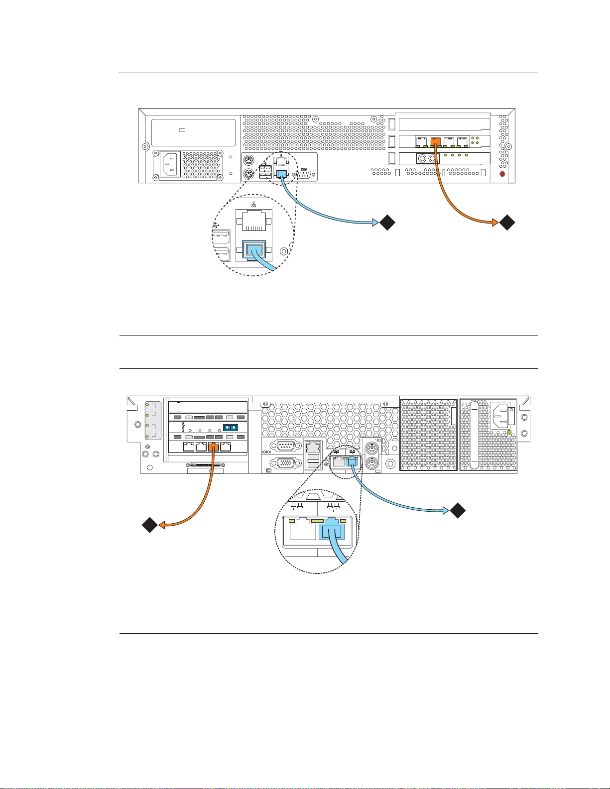
In a typical configuration, you connect to the network through a port on the back of the Avaya S8700 or
S8710 Media Server, using a stand ard CAT5 cable with RJ45 connectors on each end. T ypically, for an IP
Connect configuration, you connect through port 1 (Eth0). For a Multi-Connect configuration, you
connect through port 5 (Eth4). See Figure 1, CAT5 cable connected to a port on the back of the Avaya
S8700 Media Server, on page 23 or Figure 2, CAT5 cable connected to a port on the back of the Avaya
S8710 Media Server, on page 23, connected to back of S8710 Media Server.
The other end of the cable connects to an Ethernet switch (router), hub, or token ring.
22 Installing and Configuring the Avaya S8700 or S8710 Media Server
June 2004
Page 23
Connecting to the customer’s network
2
1
Figure 1: CAT5 cable connected to a port on the back of the Avaya S8700 Media Server
1Introduction
cadlnetw KLC 051602
554433
DAI - 1
DUP
2
1
MEMORY
1
22
AVAYA
LINE
RECEIVE
TRANS
LINK
STAT
2
Figure notes
1 To network (nondedicated control network)
2 To network (dedicated control network)
Figure 2: CAT5 cable connected to a port on the back of the Avaya S8710 Media Server
3
LINC
ACTIVE
LINC
SYNC
TRANS
MODE
RECEIVE
2
MODE
VDCI
3
100 MGz
DAL1
DUP
MEMORY
2
100 MGz
133 MGz
1
iLO
2 1
UID
cadsnet2 KLC 043004
2 1
1
2
Figure notes
1 To network (nondedicated control network)
2 To network (dedicated control network)
Installing and Configuring the Avaya S8700 or S8710 Media Server 23
June 2004
Page 24

1 Introduction
Connecting the USB modems
Connecting the USB modems
If you have not connected the modems yet, do so now.
!
WARNING:
Once you cable the modems to the media servers, do not unplug the modem USB cable on the
active server. If the modem must be replaced, replace it when the media server is in standby mode.
NOTE:
USB and serial modems cannot connect to rotary lines. A Touch Tone line is required.
When you configure the media server, you set the modem options. No options are set on the modems
themselves.
Connecting to collocated servers
Both servers share one telephone line. To connect to collocated servers:
1 Install two RJ 11 jack outlets wired to a single 1MB ( M easured Business) telephone line.
2 Connect the RJ11 jacks, one to each media server , using the m odular telephone cor d supplied with
the modem.
3 Connect one modem, using the USB cable supplied with the modem, to media server 1.
4 Connect the other modem, using the USB cable, to media server 2.
Connecting to separated servers
Each server has a dedicated telephone line. To connect to separated servers:
1 Install one RJ11 jack outlet wired to a single 1MB telephone line for a media server in each
location.
2 Connect the RJ11 jack to each media server, using the modular telephone cord supplied with the
modem.
3 Connect each modem, using the USB cable, to the media server at each location.
NOTE:
For more information on media servers in two locations, see Job Aid: Server and CSS
Separation—Avaya S8700 or S8710 Media Server (555-245-766).
24 Installing and Configuring the Avaya S8700 or S8710 Media Server
June 2004
Page 25

High level overview of installation process
High level overview of installation process
The installation process is completed in stages. Some stages can be completed in parallel, and others
require that certain tasks be accomplished before the stages can be completed. The order that the
particular stages are completed depends on local practice and the personnel available. The high level
stages are listed below.
Installing and cabling the media server complex
You can complete this stage before, in parallel with, or after installing the media gateways. See the Quick
Start for Hardware Installation: Avaya S8700 or S8710 Media Server (555-245-703)
Installing Avaya Communication Manager
The media server is shipped with a blank hard drive. The operating system, directories, and files needed
for the media server are installed from a bootable CD containing the operating system and Avaya
Communication Manager. This stage is usually done immediately after installing the media server
hardware.
Configuring the media server
Use the A vaya Installation W izard to configure the media server. You must have the filled-out Electronic
Preinstallation Worksheet (EPW) that provides the customer’s network information needed for
configuring the network components. As part of the Wizard, you install the license and Avaya
authentication files. This stage is done after installing the software.
Translating the IPSIs
This stage is done after the media servers are configured. Once the license file is installed (as part of the
A vaya Installation W izard), y ou have 30 minutes to complete this step before the license file looks for the
reference IPSI.
Installing and cabling the media gateways
You can do this stage before, in parallel with, or after installing and configuring the media server
complex. The media gateways must be installed and powered up to effectively complete many of the
other stages. The IPSI circuit packs can only be programmed in a powered up media gateway.
Installing and Configuring the Avaya S8700 or S8710 Media Server 25
June 2004
Page 26

High level overview of installation process
Completing the installation administration
This stage finishes the installation. Clearing alarms, enabling alarm reporting, backing up the server files,
and registering the configuration. This stage always comes at the end of the complete installation.
Testing the complete installation
This stage verifies the complete configuration operation and is the last task.
26 Installing and Configuring the Avaya S8700 or S8710 Media Server
June 2004
Page 27

2 Configuring the hardware in the rack
Once the control network equipment is installed and connected, you must configure the SNMP Modules
in each UPS (if Avaya supplied), the SNMP Subagent in the Avaya Ethernet switch (if Avaya supplied),
and the two media servers. The first two are to allow that equipment to send alarms (traps) to the media
servers.
Configure the SNMP agents first, then install Avaya Communication Manager on and configure the first
media server and verify its operation before you install Avaya Communication Manager on and configure
the second media server.
This section covers the following tasks:
• Configuring the SNMP modules in the UPS on page 28
• Configuring the SNMP subagent in the Avaya Ethernet switch (if used) on page 31
• Configuring the media server on page 33
• Configuring second media server on page 41
2Configuring the hardware in the rack
Installing and Configuring the Avaya S8700 or S8710 Media Server 27
June 2004
Page 28

Configuring the SNMP modules in the UPS
Configuring the SNMP modules in the UPS
NOTE:
These instruction apply only if using a new, Avaya-supplied uninterruptible power supply
(UPS) with a simple network management protocol (SNMP) module. Do not use these
procedures to set traps on a non-Avaya-provided UPS.
NOTE:
Because the SNMP module is manufactured by a third party, we do not know which
brand, model, or firmware load the factory is shipping. Therefore, we can not provide
specific instructions in this document on how to connect to and configure the SNMP
module. Refer to the documentation that comes with the SNMP module.
Make sure the CAT5 straight-through cables are connected from the UPSs’ SNMP modules to the next
available port on the customer’s network. For a connectivity guide, see Quick Start Hardware
Installation: Avaya S8700 or S8710 Media Server (555-245-703). Make sure you are plugged into the
correct port on the SNMP module.
The SNMP module in each UPS must be administered so it reports alarms to the appropriate media ser ver
when the hardware experiences problems. The module reports the loss of commercial power and the
depletion of battery resources.
The SNMP module requires a unique IP address, which can be a customer-provided one or the Avayaprovided de fault one. At a minimum, the following items need to be configured:
• IP address (1 for each UPS)
• Default gateway IP address (1 only)
• Subnet mask
• Community name strings (get, set, trap)
NOTE:
For the SNMP module to properly report alarms, the IP address for the UPS must also be
configured in the media server.
!
WARNING:
It is critical that each UPS report SNMP traps to the media server it is powering. For example,
media server 1 should be plu gged int o UP S 1, an d UPS 1 must be confi gured to report SNMP traps
to the media server 1 actual IP address (not the Active Server address). The same required
relationship holds true for media server 2 and UPS 2. This is important because if the UPS detects
loss of commercial power and/or depletion of battery resources, it will send a trap to allow the
media server to lower the media server’s state of health to cause an interchange. If the UPS sends
the trap to the wrong server trap receiver address, that media server will interchange to the media
server that is plugged into the failing UPS.
See Setting selected traps (alarming)
on page 30 for information on which traps to set.
See the local configuration section of the User’s Guide that comes with the SNMP module for the default
password and the configur ation commands.
28 Installing and Configuring the Avaya S8700 or S8710 Media Server
June 2004
Page 29

Configuring the SNMP modules in the UPS
To administer the SNMP modules:
1 Make sure the UPS is plugged into a nonswitched electrical outlet.
2 Connect the services laptop computer (RS-232 serial port) to the DB-9 connector on the back of
the SNMP module for UPS 1 using the DB-9 to DB-9 serial cable supplied with the SNMP
module.
NOTE:
Avaya Terminal Emulation and HyperTerminal are supported terminal emulation
applications.
3 On the services laptop open a VT-100 terminal emulation session.
4 Administer the terminal emulation port settings:
• 9600 baud
• No parity
• 8 data bits
• 1 stop bit
• No flow control
5 Follow the inst ructions in the User’s Guide.
6 Set the following parameters:
• IP address and subnet mask of the UPS
• For UPS1, the defaults are 198.152.254.239, 255.255.255.0.
• For UPS2, the defaults are 198.152.255.239, 255.255.255.0.
• IP address of the trap receiver. (Do not use the Active Server IP address.)
• For UPS1, this is the IP address of media server 1 (default is 198.152.254.200).
• For UPS2, this is the IP address of media server 2 (default is 198.152.255.200).
• Default Gateway address of the UPS is 198.152.254.201.
NOTE:
If a Network Management System (NMS) is going to monitor the UPS, coordinate the
assignment of community names with the network administrator. If an NMS is not going
to monitor the UPS, set the community names to unique string values.
• SNMP community string for Get, Set, and Trap.
!
SECURITY ALERT:
The Get and Set, community name strings are generally configured with default values of
Public and Private, respectively. These community name strings function as passwords
for their respective SNMP operation. It is always a good idea to change these community
name strings to something other than the default values. If a NMS is in operation on the
network, whatever these values are changed to must be coordinated with its administrator.
If the defaults are left administered this could create a serious security issue. For
example, the default Set community name string, with its widely known value of Private,
could be used to shut down power to the UPS loads via an SNMP message.
7 When completed, disconnect the services laptop computer from the UPS.
Installing and Configuring the Avaya S8700 or S8710 Media Server 29
June 2004
Page 30

Configuring the SNMP modules in the UPS
8 Connect one end of a CAT5 cable to the RJ45 connector on the UPS 1 SNMP module and the
other end to the next available port on the Ethernet switch for Control Network A (CNA).
9 Depending on whether a single or duplicated control network is installed (Single control network
on page 30 or Duplicated control network
module.
10 Connect one end of a CAT5 cable to the RJ45 connector on the UPS 2 SNMP module and the
other end to the next available port on the Ethernet switch for Control Network A (CNA).
Single control network
If a single control network, use the following address and cable connection information for UPS 2:
• UPS IP address / Subnet mask = 198.152.255.238 / 255.255.255.0
• Default Gateway IP address = 198.152.254.202
• Host Table trap receiver IP address = 198.152.254.202
• Local network administrator supplied information as required for Get and Set community name
strings.
• Cable the RJ45 connector on the UPS 2 SNMP module to the next available port on the Ethernet
switch for Control Network A (CNA).
on page 30), repeat steps 5 thru 7 for th e UPS 2 S NMP
Duplicated control network
If a duplicated control network, use the following addresses and cable connection information for UPS 2:
• UPS IPaddress / Subnet mask = 198.152.255.239 / 255.255.255.0
• Default Gateway IP address = 198.152.255.202
• Host Table trap receiver IP address = 198.152.255.202
• Local network administrator supplied information as required for Get and Set community name
strings.
• Cable the RJ45 connector on the UPS 2 SNMP module to the next available port on the Ethernet
switch for Control Network B (CNB).
Setting selected traps (alarming)
The default is to set all traps, which may result in large log entries. Therefore, only set the following
traps. See the User’s Guide that comes with the SNMP module for the menus and commands for setting
these traps.
• UPS on Battery—Indicates AC fail with pending shutdown based on battery reserve available
• UPS in Bypass—Failure either Failed UPS or overload
• Replace battery—Failure of periodic (28 -day ) battery test ind icating b atter y n eeds to be replaced.
30 Installing and Configuring the Avaya S8700 or S8710 Media Server
June 2004
Page 31

Configuring the SNMP subagent in the Avaya Ethernet switch (if used)
Configuring the SNMP subagent in the A vaya Ethernet
switch (if used)
NOTE:
These instruction apply only if using a new, Avaya-supplied Avaya Ethernet switch. Do
not use these procedures to set traps on a non-Avaya-provided Ethernet switch.
NOTE:
We do not know which Avaya Ethernet switch model or firmware load the factory is
shipping. Therefore, we cannot provide specific instructions in this document on how to
configure the SNMP subagent. Refer to the documentation that comes with the switch.
The simple network management protocol (SNMP) subagent in the Avaya Ethernet switch must be
administered so it can report alarms to the media server when the hardware experiences problems.
Each Avaya Ethernet switch requires a unique IP address, which can be a customer-provided one or the
Avaya-provided default one. At a minimum, the following items need to be configured:
• IP address (1 for each Ethernet switch)
• Subnet mask
• Trap receiver IP address
• Community string (get, set, trap)
— Spanning tree
— Ethernet port speed (if applicable)
NOTE:
For the Ethernet switch to properly report alarms, the IP address(es) for the Ethernet
switch(es) must also be configured in the media servers.
See the Basic Configuration section of the Quick Start Guide and the documentation CD that comes with
the Ethernet switch for the default user ID, password, and configuration commands.
To administer the Ethernet switch(es):
1 Plug the Ethernet switch power cord into the back of the switch and the back of a UPS.
• For a single control network— connect Ethernet switch 1 fo r Control Network A (CNA)
into UPS 1.
• For a duplicated control network—connect Ethernet switch 1 for CNA into UPS 1 and
connect Ethernet switch 2 for Control Network B (CNB) into UPS 2.
2 Connect the services laptop computer (RS-232 serial por t) to the port lab eled Console on the front
of Ethernet switch 1 (CNA) using the flat cable supplied with the Avaya Ethernet switch.
3 On the services laptop open a VT-100 terminal emulation session.
Installing and Configuring the Avaya S8700 or S8710 Media Server 31
June 2004
Page 32

Configuring the SNMP subagent in the Avaya Ethernet switch (if used)
4 Administer the terminal emulation port settings:
• 9600 baud
• No parity
• 8 data bits
• 1 stop bit
5 Follow the instructions in the Quick Start Guide
6 Set the following parameters:
• IP address and subnet mask of the Ethernet switch(es)
— For Ethernet switch for CNA, the defaults are 198.152.254.240, 255.255.0.0.
— For Ethernet switch for CNB, the defaults are 198.152.255.240, 255.255.0.0.
• IP address of the trap receiver. (Do not use the Active Server IP address.)
— For Ethernet switch for CNA, this is the IP address of media server 1. (default is
198.152.254.200)
— For Ethernet switch for CNB, this is the IP address of media server 2. (default is
198.152.255.200)
• SNMP community string for Get , Se t, and Trap. (See the section on SNMP commands on
the documentation CD that comes with the Avaya Ethernet switch.)
!
SECURITY ALERT:
The Get and Set, community name strings are generally configured with default values of
Public and Private, respectively. These community name strings function as passwords
for their respective SNMP operation. It is always a good idea to change these community
name strings to something o ther than the defaul t values. If a Ne twork Management S tation
(NMS) is in operation on the network, whatever these strings are changed to must be
communicated to the NMS administrator. If the defaults are left administered this could
create a serious security issue. For example, the default Set community name string, with
its widely known value of Private, could be used to reconfigure the Ethernet switch via
SNMP message.
7 Set spanning-tree to disabled (default is enabled)
Use the command
set spanning disable.
8 If IP Connect, make sure all appropriate ports on the Ethernet switch are locked to 100 speed
using full duplex.
9 When completed, disconnect the services laptop computer from the Ethernet switch.
10 If two Ethernet switches are present for CNA, repeat steps 1 through 7 for the second switch.
11 If a duplicated control network, repeat steps 1 through 9 for the remaining Ethernet switch(es).
32 Installing and Configuring the Avaya S8700 or S8710 Media Server
June 2004
Page 33

Configuring the me dia server
A new media server comes with a blank hard drive an d a bootable CD-ROM with Linux operating system
and Release 2.1 of Avaya Communication Manager on it.
Configuring the media server
Use the instructions in
245-703) to install the media servers in the data rack. After installing the media servers, you must install
the software from the CD onto the hard drive of each media server.
This section covers the following tasks:
Quick Start for H ardware Installation: Avaya S8700 or S871 0 Med ia Server (555-
• Clearing the ARP cache on the laptop on page 33
• Powering up the media server on page 34
• Accessing the media server on page 34
• Setting up Telnet on page 34
• Installing Avaya Communication Manager on page 35
• Using the Installation Wizard on page 36
• Configuring the modem on page 39
• Testing the media server LEDs on page 40
• Disconnecting from the media server on page 40
• Configuring second media server on page 41
NOTE:
Make sure you have the filled-out Electronic Preinstallation Worksheet (EPW) before
beginning this process.
NOTE:
Make sure your networking and Web browser settings are correct. See Appendix A,
Network configuration
on page 87.
Clearing the ARP cache on the laptop
NOTE:
Depending on your laptop computer’s operating system (generally Windows 2000), you
may need to clear the Address Resolution Protocol (ARP) cache before entering a new IP
address. If you enter an IP ad dress, and your co mputer cann ot connect, then yo u may ne ed
to clear the cache.
1 On your laptop computer click Start > Run to open the Run dialog box.
2 Type command and press Enter to open a MS-DOS Command Line window.
3 Type arp -d 192.11.13. 6 and press Enter to clear the Address Resolution Protoco l (ARP) cache in
the laptop. This command responds with one of the following:
• The command line prompt when the cache has been cleared.
• The phrase: The specified entry was not found.
This is returned when the specified IP address does not currently appear in the ARP cac he.
Installing and Configuring the Avaya S8700 or S8710 Media Server 33
June 2004
Page 34

Configuring the media server
Powering up the media server
1 S8700: Connect the AC power cord to media server 1 and to UPS 1 to power it up.
S8710: Connect the AC power cord to media server 1 and to UPS 1. Press the Power button on the
front to power it up.
Accessing the media server
NOTE:
You must place the CD in the drive immediately.
1 Connect the laptop to the services port (port 2 [Eth1]) on the back of the media server using a
crossconnect cable.
2 Place the CD with Avaya Communication Manager in the CD-ROM drive on the media server.
3 Wait at least 3 minutes after powering up before starting a Telnet session to access the information
on the CD.
Setting up Telnet
NOTE:
Use a telnet session to access the information on the CD.
The Microsoft Telnet application may be set to send a carriage return (CR) and line feed (LF) each time
you press Enter. The installation program sees this as 2 key presses. If running Windows 2000/XP, you
need to correct this before you copy the Remaster Program to the hard drive.
1 Click Start > Run to open the Run dialog box.
2 Type telnet and press Enter to open a Microsoft Telnet session.
3 Type display and press Enter to see the current settings. If message says
Sending only CR
then close the dialog box.
If message says
Sending both CR & LF
then continue with step 4.
4 Type unset crlf and press Enter.
5 Type display and press Enter to verify that the settings changed. The message says
Sending only CR
6 Close the dialog box.
34 Installing and Configuring the Avaya S8700 or S8710 Media Server
June 2004
Page 35

Installing Avaya Communication Manager
CAUTION:
If after you open a Telnet session on the media server and you get a login promp t, you may
have a hard drive with software on it rather than a blank hard drive. If that is the case, go
to Remastering the hard drive
NOTE:
Use a telnet session to access the information on the CD.
1 Type telnet 192.11.13.6 and press Enter to view the first screen.
on page 41, then come back to this step.
Configuring the media server
NOTE:
T o navigate on these sc reens, use the arrow keys to mo ve to an option, then press the space
bar to select the option. Press Enter to su bmit th e screen.
2 Select Install, make sure OK is highlighted, and press Enter.
3 Select <Yes> and press Enter.
Installing and Configuring the Avaya S8700 or S8710 Media Server 35
June 2004
Page 36

Configuring the media server
4 Select <OK> and press Enter to partition the hard drive and reformat the partitions
Once the drive is properly configured, the program begins the instal latio n pro cess and rep orts the
progress.
These processes can take up to 20 minutes. When the media server is ready to reboot, the CDROM drive drawer opens. You must remove the CD from the drive at this time.
The reboot may take up to 3 minutes. The telnet session drops automatically.
Using the Installation Wizard
You can configure the media server and install the license, Avaya authentication files, and software
updates automatically using the Avaya Installation Wizard. You can do it two ways:
• You can import the data from the filled-out Electronic Preinstallation Worksheet (EPW).
• You can also type in the information manually using the filled-out EPW as a guide.
NOTE:
You can install the license file without being physically connected to the reference IPSI.
However, you have only 30 minutes before it checks the serial number on the IPSI. To get
another 30 minutes, you can restart the clock by restarting the media server. In a SAT
session, type
reset system 1.
36 Installing and Configuring the Avaya S8700 or S8710 Media Server
June 2004
Page 37

Configuring the media server
1 Launch the Web browser.
2 In the Address field, type 192.11.13.6 and press Enter to bring up the login Web page.
NOTE:
The first time you attempt to log in, you get a Web page asking you to install a security
certificate. Follow the instructions for your particular browser to accept the certificate.
You can also install the certificate on your services laptop computer by following the
instructions in your browser’s online help.
3 Log in as craft and use the initial craft password.
4 When asked Do you want to su ppress alarms?, select Yes.
NOTE:
On the initial Web page, some items may not appear at first. These include Launch Avaya
Station Administration Wizard in the Administration section and the Upgrade section
including Launch Upgrade Tool.
5 Click Launch Avaya Installation Wizard.
6 Follow the prompts, using Help on each page for more information.
Installing and Configuring the Avaya S8700 or S8710 Media Server 37
June 2004
Page 38

Configuring the media server
Verifying media server connection to the customer’s LAN (if provided)
To verify media server connection to the customer’s LAN:
1 Under Diagnost ics, click Ping.
2 Select "Host Name Or IP Address" and type in the IP address of a computer on the network.
3 Click Execute Ping.
4 Ver ify that the ping was successful, ind icating that the media ser ver is connected to the cus tomer’s
network.
5 If DNS is administered, type in the host name of a computer on the network.
6 Click Execute Ping.
7 Verify that the ping was successful, indicating that DNS is working.
If available, have a customer representative do the following test from a computer on the network:
8 Click Start > Run to open the Run dialog box.
9 Type command and click OK to open an MS-DOS command window.
10 Type ping serveripaddress and click OK, where serveripaddress is th e IP addr ess of the med ia
server.
11 Verify that the ping was successful.
12 If DNS is administered, type ping servername and press Enter, where servername is the host
name of the media server.
13 Verify that the ping was successful.
38 Installing and Configuring the Avaya S8700 or S8710 Media Server
June 2004
Page 39

Configuring the modem
1 Under Server Configuration click Configure Server.
2 Click through until you get to the Specify how you want to use this wizar d page
3 Select Configure individual services and click Continue.
Configuring the media server
4 In the left menu click Set Modem Interface.
Installing and Configuring the Avaya S8700 or S8710 Media Server 39
June 2004
Page 40

Configuring the media server
5 Select the Change Modem Setting and click Continue.
6 In the AT Str ing field, type the initializat ion comma n ds appropr iate for you r modem and countr y
of operation. Click Help for guidance on what to enter.
For example, to change the country code to Japan, type
AT%T19,0,10.
7 Click Change.
The system responds with a message indicating a successfully added modem route.
8 Click Close Window.
Testing the media server LEDs
1 Under Diagnostics, click Test Server LEDs to test the media server LEDs.
2 Observe the Active/Standby and U2 LEDs on the front of the media server and the transmit LED
on the duplication card on the back of the media server to ensure they are blinking. The blinking
stops after about a minute.
1
Disconnecting from the media server
1 Unplug the crossconnect cable from the services port on the back of the media server.
40 Installing and Configuring the Avaya S8700 or S8710 Media Server
June 2004
Page 41

Configuring second media server
The procedures for this installation are the same as for configuring the first media server. Repeat tasks
Clearing the ARP cache on the laptop
40 for the second media server.
Remastering the hard drive
CAUTION:
This task is not part of the ordinary configuration process and erases any information on
the drive. Do not perform this tas k unless you are upd ating from a release prior to Release
2.1 of Avaya Communication Manager.
NOTE:
This step upgrades the server, loading the RP software onto the backup partition. The
currently running release remains on the other partition, just as it always does during an
upgrade.
on page 33 through Disconnecting from the media server on page
Configuring second media server
1 Insert the CD containing the software into the CD-ROM drive on the media server and close the
tray.
2 Under Server Configuration and Upgrades, click Install New Software Release.
3 Select from the menu the file from the CD (S8700-00.0-0000.0 ). Cli ck Continue to complete the
software installation.
On the page asking about installing the license file, select either statement and click Continue.
The license file is replaced later in the upgrade process.
On the page asking about installing the Avaya authentication files, select Do not update
authentication information and click Continue.
4 Select Reboot when you get to that Web page.
After the system reboots, which takes about 3 minutes, the RP software redirects the system to
boot from the CD-ROM drive. This is the same software that would have loaded if the CD were
bootable. Note that no telephony support is provided by this software. Its only purpose is to
reformat the hard drive and install a clean copy of the Avaya Communication Manager server
software.
5 Close the browser.
Installing and Configuring the Avaya S8700 or S8710 Media Server 41
June 2004
Page 42

Configuring second media server
42 Installing and Configuring the Avaya S8700 or S8710 Media Server
June 2004
Page 43

3 Translating the IPSIs
These steps are done by issuing SAT commands on a terminal emulation program such as Avaya Native
Configuration Manager, Avaya Terminal Emulation, or HyperTerminal. You also can use Avaya Site
Administration, part of the Avaya Integrated Management suite, which you can purchase from Avaya.
NOTE:
You must use Release 1.11 or a later version of Avaya Site Administration, to administer
new features in Release 2.1 of Avaya Communication Manager.
NOTE:
For SAT commands you must be on the active media server.
Perform these tasks to customize the media server:
• Starting terminal emulation on page 43
• Inputing translations on page 44
• Resetting the media server on page 44
3Translating the IPSIs
Starting terminal emulation
• Adding media gateways on page 44
• Administering the IPSIs on page 45
Starting terminal emulation
NOTE:
A vaya Native Configur ation Manager , Avaya Terminal Emulation, and HyperTerminal are
supported terminal emulation applications.
1 On the services laptop, open a VT-100 terminal emulation session.
2 Administer the terminal emulation port settings:
• 9600 baud
• No parity
• 8 data bits
• 1 stop bit
• No flow control
• 5023 for the port
3 Log into the media server as craft.
Installing and Configuring the Avaya S8700 or S8710 Media Server 43
June 2004
Page 44

3 Tra nsla ting the IPSIs
Inputing translations
Inputing translations
Contact the installation personnel responsible for translation input to download the translations.
1 Type save translations and press Enter to save the translations to the hard drive.
If the translations are not ready, you may continue with the process, entering minimal translations to
verify connectivity to the port networks.
Resetting the media server
NOTE:
Do not reset the media server if no translations were input or if they were not entered in
bulk.
1 Type reset sys tem 4 and press Enter to have the software read the copied translations.
Adding media gateways
NOTE:
Do this procedure only if the translations were not input earlier.
NOTE:
A cabinet is defined as up to 5 G650 Media Gateways mounted in a rack and TDMconnected or 1 MCC1 Media Gateway.
1 Type add cabinet number (1 through 64) and press Enter for each stack of G650 Media
Gateways or MCC1 Media Gateway controlled by one TN2312BP IPSI circuit pack.
2 Fill in the location and carrier type for media gateways 2(B), 3(C), 4(D), and 5(E).
add cabinet 1 Page 1 of 1
CABINET DESCRIPTION
Cabinet: 9
Cabinet Layout: G650-rack-mount-stack
Cabinet Type: expansion-portnetwork
Location: 1
Rack: Room: Floor: Building:
CABINET
CARRIER DESCRIPTION
Carrier Carrier Type Number
E not-used PN 09
D not-used PN 09
C not-used PN 09
B G650-port PN 09
A G650-port PN 09
44 Installing and Configuring the Avaya S8700 or S8710 Media Server
June 2004
Page 45

Administering the IPSIs
NOTE:
This procedure enables the IPSI circuit packs and allows them to control the port
networks.
1 Type change system-parameters ipserver-interface and press Enter.
change system-parameters ipserver-interface Page 1 of 1
IP SERVER INTERFACE (IPSI) SYSTEM PARAMETERS
SERVER INFORMATION
IPSI Host Name Prefix: vodka
Primary Control Subnet Address: 198.152.254. 0 *
Secondary Control Subnet Address: 198.152.255. 0 *
OPTIONS
Switch Identifier: A
IPSI Control of Port Networks: enabled
3Translating the IPSIs
Administering the I PSIs
2 Verify that the Primary and Secondary Subnet Addresses are correct.
The subnet addresses must match the most significant 3 octets (the first three groups of digits in
the subnet address) of the Server IP address.
An asterisk (*) to the right of the
displayed, it is not the correct one; Avaya Communication Manager does not have the subnet
information. After verifying the displayed information, su bmit this form with or without changes
to update the software with the correct subnet information.
CAUTION:
If the information displayed in the Primary Control Subnet Address and/or Secondary
Control Subnet Address
Use the Maintenance Web Interface; under Server Configuration and Upgrades, click
Configure Server to change the media server configuration. Then return here to perform
this step.
3 Set the Switch Identifier: field to the switch ID letter (A thru J; A is the default setting).
4 Set the IPSI Control of Port Networks: field to enabled.
5 Press Enter to effect the change.
Adding IPSI information
Subnet Address field means that although a subnet address is
fields is not correct, it must be changed on the media servers.
NOTE:
The information you provide differs, depending on whether the IPSIs get static addresses
or they are assigned automatically through DHCP.
Installing and Configuring the Avaya S8700 or S8710 Media Server 45
June 2004
Page 46

3 Tra nsla ting the IPSIs
Administering the IPSIs
1 Type add ipserver-interface PNnumber and press Enter to add the IPSI circuit pack
information.
2 When using a DHCP server, verify that the f ields associated with the Primary IPSI and Secondary
IPSI (if equipped) are populated with default data.The Host: and DHCP ID: fields are set by
the DHCP server.
add ipserver-interface 4 Page 1 of 1
IP SERVER INTERFACE (IPSI) ADMINISTRATION - PORT NETWORK 4
IP Control? y Socket Encryption? n
Enable QoS? n
Primary IPSI
----------- Location: 9A01
Host: ipsi-A09a
DHCP ID: ipsi-A09a
Secondary IPSI
------------- Location: 9B01
Host: ipsi-A09b
DHCP ID: ipsi-A09b
When using static addressing, in the
network listed in the
add ipserver-interface 8
IP SERVER INTERFACE (IPSI) ADMINISTRATION - PORT NETWORK 8
IP Control? y Socket Encryption? y
Enable QoS? y
Primary IPSI QoS Parameters
------------ ------------- Location: 1A01 Call Control 802.1p: 6
Host: 172.22.22.174 Call Control DiffServ: 46
DHCP ID: ipsi-A01a
Secondary IPSI
------------- Location: 1B01
Host: 172.22.22.175
DHCP ID: ipsi-A01b
Location: field.
Host: field, type in the IP address for the IPSI in the port
3 Set the IP Control? field to y.
4 Verify that all the other fields are populated.
5 Press Enter to effect the changes.
6 Repeat steps 1 through 5 for each port network.
46 Installing and Configuring the Avaya S8700 or S8710 Media Server
June 2004
Page 47

Enabling IPSI duplication (duplicated control network only)
Enabling IPSI duplication requires that all IPSI-connected port networks have both primary (CNA) and
secondary (CNB) IPSI circuit packs. Disabling IPSI duplication requires that all primary IPSI circuit
packs be active.
1 Type change system-parameters duplication and press Enter.
S8700/S8710 MC:
change system-parameters duplication Page 1 of 1
DUPLICATION RELATED SYSTEM PARAMETERS
Enable Operation of PNC Duplication? y
Enable Operation of IPSI Duplication? y
3Translating the IPSIs
Administering the I PSIs
S8700/S8710 IP:
change system-parameters duplication Page 1 of 1
DUPLICATION RELATED SYSTEM PARAMETERS
Enable Operation of IPSI Duplication? n
2 Set the Enable Operation of IPSI Duplication? field to y.
3 Press Enter to effect the changes.
Installing and Configuring the Avaya S8700 or S8710 Media Server 47
June 2004
Page 48

3 Tra nsla ting the IPSIs
Administering the IPSIs
Setting alarm activation level
1 Type change system-parameters maintenance and press Enter.
change system-parameters maintenance Page 1 of 3
MAINTENANCE-RELATED SYSTEM PARAMETERS
OPERATIONS SUPPORT PARAMETERS
CPE Alarm Activation Level: none
SCHEDULED MAINTENANCE
Start Time: 22 : 00
Stop Time: 06 : 00
Save Translation: daily
Update LSPs When Saving Translations: y
Command Time-out (hours): 2
Control Channel Interchange: no
System Clocks/IPSI Interchange: no
2 In the CPE Alarm Activation Level field, select none (default), warning, minor, or major,
depending on the level the customer wants and press
Enter to effect the changes.
3 Repeat for each IPSI.
Installing the translation file
1 Type save translations and press Enter to save the translations to the hard drive.
48 Installing and Configuring the Avaya S8700 or S8710 Media Server
June 2004
Page 49

4 Connecting to the IPSIs
NOTE:
The media gateways must be installed, connected to each other, and powered up.
This chapter covers the following tasks:
• Programming the IPSI circuit packs on page 50
• Using DHCP addressing on page 50
• Using static addressing on page 51
• Verifying that IPSIs are translated on page 54
• Verifying connectivity to media server on page 55
• Upgrading IPSI firmware version (if necessary) on page 55
• Enabling control of IPSIs on page 55
• Verifying license status on page 56
4Connecting to the IPSIs
• Reusing a TN2312AP/BP circui t pack on page 56
NOTE:
At a minimum you must program the reference IPSI and connect to it to avoid going into
No License Mode.
NOTE:
Once the IPSIs are connected to the control network, they may alarm if the firmware is not
the most current. The alarm automatically goes away once the IPSI firmware is upgraded.
Single control network: Connect one end of the GREEN CAT5 straight-through cable to the IPSI
adapter on the back of media gateway in position A.
Duplicated control network: In addition connect one end of the RED CA T5 straight-through cable to the
IPSI adapter on the back of media gateway in position B.
Dedicated control network: The other end is connected to the next available port on the Ethernet switch.
Nondedicated control network: The other end is connected to the next available port on the customer’s
network.
For a connectivity guide, see Quick S t art f or Ha r d ware Installat ion: Avaya S8700 or S8710 Media Server
(555-245-703).
Installing and Configuring the Avaya S8700 or S8710 Media Server 49
June 2004
Page 50

4 Connecting to the IPSIs
Programming the IPSI circuit packs
Programming the IPSI circuit packs
IP server interface (IPSI) circuit packs get IP addresses in one of two ways:
• Using dynamic host configuration protocol (DHCP), if a dedicated (private) control network
• Using static IP addressing, if a nondedicated (public) control network.
NOTE:
Before beginning, read this procedure to familiarize yourself with it. With DHCP
addressing, there are certain sequences that need to be completed before a predetermined
time-out interval.
Using DHCP addressing
For the TN2312BP IPSI circuit pack s to get IP addre sses dynamical ly, you must first assign the switch ID
(A through J) and the cabinet number (01 through 64) to each IPSI circuit pack. For G650 Media
Gateways, a cabinet is defined as one or more media gateways connected by TDM cable, which is called
a G650-rack-mount-stack.
Administering the location assignment
1 Fully insert the TN2312BP IPSI circu it p a ck. If necessary, reseat the circuit pack to begin the
programming sequence.
NOTE:
You must do the following steps within 5 seconds after inserting the circuit pack.
2 Insert a pen, golf tee, or similar object (no graphite pencil) into the recessed push button switch.
CLK
S
E
R
fpdlled3 LJK 022502
V
NOTE:
If you pass up the letter or number that you want, you must either cycle through all the
letters or numbers to get to the one you want or reinsert (reseat) the circu it pack and begin
again.
50 Installing and Configuring the Avaya S8700 or S8710 Media Server
June 2004
Page 51

Programming the IPSI circuit packs
Setting the switch ID
If you have only one system, the default switch ID is A. The second system would be B and so on. The
switch ID is not the media gateway or carrier letter.
1 While the display is flashing, press the button until the switch ID (A through J) shows on the top
character of the LED display. When the correct letter shows, stop. It will flash a few times (5
seconds) then stop. The next character down begins to flash.
Setting the cabinet number
The number to program is the cabinet number not the port network number. If you have more than one
IPSI in a cabinet, they all have the same cabinet number.
1 While the first di git of the numb er is flash ing, press the button until the correct tens digit (0
through 6) shows on the display. When the correct digit shows, stop. It flashes a few times then
stops (five seconds). The second digit begins flashing.
2 While the second digit is flashing, press the button until the correct units digit (0 through 9) shows
on the display. When the correct digit shows, stop. The digit flashes a few times then stops (five
seconds).
3 All segments of the display goes dark for one second, and then the Switc h ID and media gat ewa y
stack number is displayed in the top three characters of the LED display. A "V" is shown in the
fourth character (bottom) of the display. When the DHCP server assigns an address to the IPSI,
the center of the "V" is filled in to form the bottom half of a diamond in the display.
4Connecting to the IPSIs
For duplicated control network, repeat these steps for the second IPSI in the cabinet.
Using static addressing
For the IPSI circuit packs to get static IP addresses, you must administer them directly through the
Ethernet port connection on the IPSI faceplate (top port). See Figure 1, Connecting directly to the IPSI,
on page 52.
CLK
S
E
R
fpdlled2 LJK 022502
V
Installing and Configuring the Avaya S8700 or S8710 Media Server 51
June 2004
Page 52

4 Connecting to the IPSIs
Programming the IPSI circuit packs
Figure 1: Connecting directly to the IPSI
1
cadlipsi KLC 031502
Figure notes
1 Services laptop
2 PCMCIA Network Interface Card (NIC)
NOTE:
Make sure you have the password before proceeding.
CLK
S
E
R
V
I
C
E
N
E
2
T
W
O
R
K
3
4
3 NIC adapter cable (if necessary)
4 CAT5 crossover cable to IPSI
1 Connect the services laptop computer to the top port on the IPSI circuit pack faceplate.
2 From the services laptop Start Menu, click Start > Run to open the Run dialog box.
3 Type command and press Enter to open a MS-DOS Command Line window.
4 Type arp -d 192.11.1 3.6 and press Enter to clear the ARP cache in the laptop. This command
responds with one of the following:
• The command line prompt when the cache has been cleared.
• The phrase: The specified entry was not found. This is returned when the specified IP
address does not currently contain an entry in the ARP cache.
5 Type telnet 192.11.13.6 and press Enter to open the Telnet window and connect to the IPSI
Prompt = [IPSI]:
NOTE:
While connected to the IPSI, type help or ? to obtain online help. Most commands have
two or three letter abbreviations.
52 Installing and Configuring the Avaya S8700 or S8710 Media Server
June 2004
Page 53

Programming the IPSI circuit packs
6 Type ipsilogin and press Enter (abbreviated command = il).
NOTE:
The craft login used on the IPSI has a different password than the craft login used on the
media servers.
7 Log in as craft.
Prompt = [IPADMIN]:
Type show control interface and press Enter. 8Type show po rt 1 and press Enter to see the current
settings.
9 Type set control interface ipaddr netmask and press Enter, where ipaddr is the customer-
provided IP address and
netmask is the customer provided subnet mask.
4Connecting to the IPSIs
10 Press Enter to effect the changes.
11 Type show control interface and press Enter.
The IP address, subnet mask, and default gateway information will be displayed.
Verify that the proper information was entered.
12 If required, type set control gateway gateway and press Enter, where gateway is the customer-
provided IP address for their gateway.
13 Press Enter to effect the changes.
14 If required, use the set vlan priority, set vlan tag, set vlan id, set port negotiation (1=disable),
set port duplex (1 full), set port speed (1 100 MB), and set diff serv commands to enter VLAN
and diffserv parameters for the IPSI. Use Help to obtain syntax guidelines for these commands.
15 Type reset and press Enter
Answer Y to the warning.
NOTE:
Resetting the IPSI terminates the administration sessio n. If further administration is
required, start a new telnet session to the IPSI.
Installing and Configuring the Avaya S8700 or S8710 Media Server 53
June 2004
Page 54

4 Connecting to the IPSIs
Verifying that IPSIs are translated
16 Type quit to logoff the IPSI.
17 Check the LCD. Verify that it has an I P with a filled-in V showing at the bottom. (See Figure 2,
LED display showing that the IPSI has a static IP address, on page 54)
Figure 2: LED display showing that the IPSI has a static IP address
NOTE:
Control network settings (IP address, subnet mask, and gateway) become effective when
you exit the IPADMIN session.
CLK
S
E
R
V
18 Disconnect the laptop from the faceplate.
NOTE:
Always use the arp -d 192.11.13.6 command (step 4) to clear the ARP cache on the
laptop before connecting to another IPSI. If the cache is not cleared the laptop appears to
hang and does not connect to the next IPSI.
19 Repeat for each IPSI circuit pack.
Verifying that IPSIs are translated
NOTE:
You must be on the active media server to use SAT commands.
1 Type list ipserver-interface and press Enter.
2 Verify that all IS PI circuit packs are translated.
fpdlled1 LJK 022502
54 Installing and Configuring the Avaya S8700 or S8710 Media Server
June 2004
Page 55

Verifying connectivity to media server
Verifying connectivity to media ser ve r
1 If not already open, open a browser and log in as craft.
2 Click Launch Maintenance Web Interface.
3 Under Diagnostics, click Ping and select Other server(s), All IPSIs, UPS(s), Ethernet switches
to verify connectivity to these units.
4 Click Execute Ping.
5 Verify that all endpoints respond correctly.
Upgrading IPSI firmwar e version (if necessary)
You may need to upg rade t he f irmw are o n s ome or all the IPSIs. All IPSIs must be on the same firmware
load.
1 Under IPSI Firmware Upgrades click IPSI Version.
4Connecting to the IPSIs
2 Select Query All and click View IPSI Version.
3 Ver if y the firmware release for each TN2312BP IPSI. If an upgrade is required, follow the
procedures inUpgrading Software and Firmwar e—Avaya S8700 or S8710 Media Server (555-
245-115), Upgrading IPSI Firmware.
Enabling control of IPSIs
NOTE:
Make sure the IPSIs have the same, current firmware.
If a duplicated IPSIs, make sure that IPSI duplication is enabled before enabling IPSI
control. See Enabling IPSI duplication (dupl i cated control network only)
NOTE:
This procedure enables the IPSI circuit packs and allows them to control the port
networks.
on page 47.
Installing and Configuring the Avaya S8700 or S8710 Media Server 55
June 2004
Page 56

4 Connecting to the IPSIs
Verifying license status
1 Type change system-parameters ipserver-interface and press Enter.
change system-parameters ipserver-interface Page 1 of 1
IP SERVER INTERFACE (IPSI) SYSTEM PARAMETERS
SERVER INFORMATION
IPSI Host Name Prefix:
Primary Control Subnet Address: 172. 22. 0. 0
Secondary Control Subnet Address: . . .
OPTIONS
Switch Identifier: A
IPSI Control of Port Networks: enabled
2 Make sure the IPSI Control of Port Networks: field is set to enabled.
3 Press Enter to effect the changes.
Verifying license status
1 Under Security, click License File and verify that the license mode is now normal.
Reusing a TN2312AP/BP circuit pack
On occasion a customer may want to reuse a TN2312AP or TN2312BP circuit pack that was previously
programmed for DHCP or static addressing. You must erase the existing programming before
reprogramming it. Failure to do this may result in serious network problems.
For information on erasing the programming, go to the Maintenance Procedures for Avaya
Communication Manager 2.1, Media Gateways and Servers (03-300192).
56 Installing and Configuring the Avaya S8700 or S8710 Media Server
June 2004
Page 57

5 Completing the installation
administration
This section covers the following tasks:
• Verifying transla tions on page 57
• Setting daylight savings time rules on page 58
• Setting locations (if necessary) on page 59
• Verifying date and time on page 59
• Resolving alarms on page 60
• Enabling and disabling Ethernet switch ports on page 60
• Backing up files to the compact flash media (S8710 only) on page 61
• Backing up files to the PCMCIA flashcard (S8700 only) on page 63
• Telneting to media server on page 65
5Completing the installation administration
Verifying transla tions
• Enabling alarms on page 65
• Registering the system on page 66
Verifying translations
1 Type list configuration all and press Enter to view all the administered circuit packs in the
system.
2 Type list ipsi and press Enter to verify the location of the IPS I circu it packs.
3 Check the administration status on the following items:
• list station
• list trunk-group
• list hunt-group
NOTE:
Even though you set the date, time, and time zo ne through the Web interface on the media
server, you also must set the daylight savings time rules and locations and verify the date
and time through SAT commands.
Installing and Configuring the Avaya S8700 or S8710 Media Server 57
June 2004
Page 58

5 Completing the installation administration
Setting daylight savings time rules
Setting daylight savings time rules
You can set up to 15 customized daylight savings time rules. If you have media gateways in several
different time zones, you can set up rules for them on a per-location basis. A daylight savings time rule
specifies the exact time when you want to transition to and from daylight savings time. It also specifies
the increment at which to transition.
NOTE:
The default daylight savings rule is 0, meaning no daylight savings transition.
1 Type change daylight-savings-rules and press Enter.
change daylight-savings-rules Page 1 of 2
DAYLIGHT SAVINGS RULES
Rule Change Day Month Date Time Increment
0: No Daylight Savings
1: Start: first Sunday on or after April 1 at 02:00 01:00
Stop: first Sunday on or after October 25 at 02:00
2: Start: first on or after at : :
Stop: first on or after at :
3: Start: first on or after at : :
Stop: first on or after at :
4: Start: first on or after at : :
Stop: first on or after at :
5: Start: first on or after at : :
Stop: first on or after at :
6: Start: first on or after at : :
Stop: first on or after at :
7: Start: first on or after at : :
Stop: first on or after at :
2 In the Change Day, Month, Date, Time, and Increment fields, type the appropriate Start and Stop
information for each rule. For example, 1:00 in the
forward or back by one hour at the transition point.
NOTE:
You can change any rule except rule 0 (zero). You cannot delete a daylight savings rule if
it is in use on either the Locations or Date and Time scree ns.
Increment field means to move the clock
3 When done, press Enter to effect the changes.
58 Installing and Configuring the Avaya S8700 or S8710 Media Server
June 2004
Page 59

Setting locations (if necessary)
After you set the daylight savings rules, you must set the locations for all media gateways (cabinets). It is
possible to have media gateways in different time zones.
1 Type change locations and press Enter.
change locations Page 1 of 5
LOCATIONS
ARS Prefix 1 Required For 10-Digit NANP Calls? y
Number Name Timezone Daylight-Savings Number Plan
Offset Rule Area Code
1 Main + 00:00 0
2 CA - 02:00 0
3 :
4 :
5 :
6 :
7 :
8 :
9 :
10 :
11 :
5Completing the installation administration
Setting locations (if necessary)
2 In the ARS Prefix 1 Required for 10-Digit NANP Calls? field, type y.
3 Type the information in the various fields for each media gateway.
NOTE:
In the Name field for location 1, call the media gateway (cabinet) Main.
4 Press Enter to effect the changes.
Verifying date and time
1 Type display time and press Enter.
display time Page 1 of 1
DATE AND TIME
DATE
Day of the Week: Friday Month: November
Day of the Month: 8 Year: 2002
TIME
Hour: 14 Minute: 19 Second: 36 Type: Standard
Daylight Savings Rule: 0
WARNING: Changing the date or time may impact BCMS, CDR, SCHEDULED
2 Verify that the date and time are correct.
Installing and Configuring the Avaya S8700 or S8710 Media Server 59
June 2004
Page 60

5 Completing the installation administration
Resolving alarms
3 Verify that the correct rule (number) is displayed in the Daylight Savings Rule field.
4 If correct, press Cancel.
5 If not, go to the Maintenance Web Interface.
6 Under Server, click Set Server Time/Timezone.
7 Verify that the date and time are correct. If not, set it here.
8 Repeat steps 1 through 3.
Resolving alarms
NOTE:
You can only resolve alarms on the active media server.
1 Under Alarms click Current Alarms.
2 Select the server alarms to be cleared and click Clear.
3 Resolve any major alarms using SAT commands and a terminal emulation application, such as
Native Configuration Manager or MS HyperTerminal.
Enabling and disabling Ethernet switch ports
You may want to disable unused ports on the Avaya Ethernet switch (if used). To enable or disable
Ethernet switch ports:
1 Under Security, click Ethernet Switch Ports to select an Ethernet switch to administer.
60 Installing and Configuring the Avaya S8700 or S8710 Media Server
June 2004
Page 61

Backing up files to the compact flash media (S8710 only)
2 Select the switch you want to administer and click Submit.
5Completing the installation administration
3 Locate the port(s) you want to disable and click on the button in the Disable column.
4 Click Submit Changes.
Backing up files to the compact flash media (S8710
only)
1 Connect the compact flash drive to one of the USB ports on the back of the media server.
2 Insert a 128-Mb compact flash media into the top right slot of the drive.
NOTE:
The industrial grade compact flash media provides improved data integrity and reliability,
enhanced durability , and extreme en durance. For these reasons Avaya recommends the use
of an industrial grade compact flash. To read more about the industrial grade compact
flash, see the Hardware Guide for Avaya Communication Manager (555-245-207).
Installing and Configuring the Avaya S8700 or S8710 Media Server 61
June 2004
Page 62

5 Completing the installation administration
Backing up files to the compact flash media (S8710 only)
NOTE:
You must format the compact flash media before writing to it.
3 Under Data Backup/Restore click Backup Now.
4 Select all applicable data sets.
Select Save ACP transl ations prior to backup to save translations to the media server’s system
disk before backing up the data.
62 Installing and Configuring the Avaya S8700 or S8710 Media Server
June 2004
Page 63

Backing up files to the PCMCIA flashcard (S8700 only)
5 Select either Local PC Card and Format PC Card, or Format PC Card (the second such selection
further down the screen).
Use Local PC Card and Format PC Card to format the PC card and back up the data onto it.
Use Format PC Card to format new cards or to overwrite an existing card.
NOTE:
Customer’s may want to back up using another method.
6 Click Start Backup. You are notified when th e format is completed (approximately 10 seconds).
NOTE:
Clicking on Start Backup without media in the compact flash drive results in an error. To
continue with the backup, unplug the drive, insert the formatted media into the right top
slot, and plug the drive back into the USB port.
7 Click B ackup Status to view the status of the backup.
Backing up files to the PCMCIA flashcard (S8700 only)
5Completing the installation administration
1 Place the PCMCIA flashcard into the bottom slot of the PCMCIA drive in the active media server.
See Figure 3, Placing the flashcard in the media server,
Figure 3: Placing the flashcard in the media server
1
3
2
Figure notes
1 Media Server
3 Botto m slot of PCMCIA drive
2 PCMCIA flashcard
on page 63.
h1dlopt LJK 030102
Installing and Configuring the Avaya S8700 or S8710 Media Server 63
June 2004
Page 64

5 Completing the installation administration
Backing up files to the PCMCIA flashcard (S8700 only)
2 Under Data Backup/Restore click Backup Now.
3 Select all applicable data sets.
Select Save ACP translations prior to backup to save translations to the media server’s hard
drive before backing up the data.
4 Select Local PC card as the backup method.
NOTE:
Customer’s may want to back up using another method.
5 Click Backup now to back up all data to the PCMCIA flashcard.
64 Installing and Configuring the Avaya S8700 or S8710 Media Server
June 2004
Page 65

Telneting to media serve r
Enabling alarms uses Linux commands through Telnet.
1 Click Start > Run to open the Run dialog box
2 Type telnet 192.11.13.6 and press Enter.
3 Log in as craft or dadmin (if business partner).
Enabling alarms
To INADS via modem
NOTE:
These steps must be done on both media servers.
5Completing the installation administration
Telneting to media server
1 Type almenab le -d b and press Enter.
2 Type almenable and press Enter to verify that the alarms are enabled.
To INADS via SNMP
NOTE:
Do these steps only if a Secure Service Gateway (SSG) is being installed.
NOTE:
These steps must be done on both media servers.
1 Type almsnmpconf -d ipaddress -c communityname and press Enter, where ipaddress is the
trap receiver address for the SSG device and communityname is the community string name
required by the SSG device.
2 Type almsnmpconf and press Enter .
Verify that the correct information was entered.
3 At the prompt, type almenable -s y and press Enter.
4 Type almenable and press Enter.
Verify that the SNMP alarm origination is enabled. If used, verify that alarm origination via
modem is still enabled.
5 Log off.
To INADS on second server
1 Connect to the second media server
2 Repeat Telneting to media server on page 65 through Enabling alarms on page 65 on the second
server.
Installing and Configuring the Avaya S8700 or S8710 Media Server 65
June 2004
Page 66

5 Completing the installation administration
Registering the system
Registering the system
Follow the existing process and procedures to register the Avaya S8700 or S8710 Media Server.
Let customers know what the default LAN security settings are; they may want to change them after
installation. Make sure they are aware that if the following items are not enabled, they will not have
remote access to the media server:
• telnet—no Telnet access
• https—no Maintenance Web Interface access
• def-sat—no SAT command access
66 Installing and Configuring the Avaya S8700 or S8710 Media Server
June 2004
Page 67

6 Installing the media gateways
In a new installation, the Avaya S8700 or S8710 Media Servers work with only the Av aya G650 Media
Gateway . However, an Avaya MCC1 Media Gateway is provided in a multiconnect configuration when a
switch node carrier (SNC) for Center Stage Switch (CSS) is required. The MCC1 Media Gateway may
contain one port network in the A, B, C, and D positions and the SNC in the E position. For duplicated
bearer networks, the D position also may be used for the duplicated (B-PNC) SNC.
In a migration the media servers work with Avaya MCC1 and SCC1 Media Gateways in a multiconnect
configuration, and G600 or CMC1 Media Gateways in an IP configuration.
In addition, the media servers work with Avaya G350 and G700 Media Gateways, but only if the G650
Media Gateway has a TN799DP C-LAN circuit pack installed. These gateways are treated as endpoints
off the TN799DP.
Media gateways typically are installed in the same equipment room as the media server rack hardware
(control network); however, they can be installed in another location, including another state or country.
6Installing the media gateways
For information on installing media gateways, see
• Installing the Avaya G650 Media Gateway (03-300144)
• Quick Start for Hardware Installation: Avaya G350 Media Gateway (03-300148)
• Installation of the Avaya G350 Media Gateway (555-245-104)
• Quick Start for Hardware Installation: Avaya S8300 Media Server and Avaya G700 Media
Gateway (555-233-150)
• Installation and Upgrades for the Avaya G700 Media Gateway and Avaya S8300 Media Server
(555-234-100)
Installing and Configuring the Avaya S8700 or S8710 Media Server 67
June 2004
Page 68

6 Installing the media gateways
68 Installing and Configuring the Avaya S8700 or S8710 Media Server
June 2004
Page 69

Testing the TN2312BP IPSI circuit pack
7 Testing the media server installation
This chapter provides tests for the control network, including
• reviewing the status of the configuration.
• testing the IPSI circuit packs.
In addition, it provide s information on the LED status indicators for the media servers, Avaya Ethernet
switch(es), uninterruptible power supplies (UPSs), and different circuit packs. See LED indicators
page 71.
NOTE:
Circuit pack positions are usually given by cabinet, and slot. They may also be given by
port. The term cabinet refers to five G650 Media Gateway TDM-cable d together in a rack,
making up one port network. A port network is defined as a group of media gateways
connected together with one TDM bus.
Perform these tasks to test the configuration:
on
7Testing the media server installation
CAUTION:
To prevent unnecessary trouble tickets, do not enable the alarms (Alarm Origination
feature) until all installation and administration procedures are completed.
• Testing the TN2312BP IPSI circuit pack on page 69
• Testing the license file on page 70
NOTE:
Do these steps using a SAT session
NOTE:
For SAT commands you must be on the active media server.
Testing the TN2312BP IPSI circuit pack
1 Type test ipserver-interface UUC and press Enter to test all clock and packet interface
components within the IPSI circuit pack.
2 Verify the screen di splays Test Results screen similar to Figure 4, Sample IPSI 01A test results
screen—page 1, on page 70.
Installing and Configuring the Avaya S8700 or S8710 Media Server 69
June 2004
Page 70

7 Testing the media server installation
Testing the license file
Figure 4: Sample IPSI 01A test results screen—page 1
test ipserver-interface 1a Page 1
TEST RESULTS
Port Maintenance Name Alt. Name Test No. Result Error Code
01A TONE-BD 46 PASS
01A TONE-BD 52 PASS
press CANCEL to quit -- press NEXT PAGE to continue
Testing the license file
CAUTION:
Wait at least 30 minutes after you install the license before you do the test.
1 Type test license [short | long] and press Enter.
2 Verify the screen displays a Test Results screen similar to Figure 5, Sample test results screen for
test license, on page 70.
Figure 5: Sample test results screen for test license
test license
TEST RESULTS
Port Maintenance Name Alt. Name Test No. Result Error Code
LIC-ERR 1484 PASS
70 Installing and Configuring the Avaya S8700 or S8710 Media Server
June 2004
Page 71

LED indicators
See the Maintenance Alarms for Avaya Communication Manager 2.1, Media Gateways and Servers (03-
300190) for detailed alarm and LED descriptions. If a maintenance object begins to fail some periodic
tests, the media server generates an alarm. The media server identifies three levels of alarms:
• Major Alarms—Failures that cause critical degradation of service and require immediate
attention.
• Minor Alarms—Failures that cause some degradation of service, but do not cause a critical
portion of the configuration to be inoperable. This condition requires action, but its consequences
are not immediate. Problems might be impaired service to a few trunks or stations or interfering
with one feature across the entire configuration.
• Warning Alarms—Failures that cause no significant degradation of service or failures in
equipment external to the configuration. Warning alarms are not reported to the attendant console
or INADS.
Alarms are communicated to users and technicians by entries in the alarm and system logs and the
lighting of LEDs located on the media server.
7Testing the media server installation
LED indicators
More detailed information is available here for:
• S8700 Media Server LEDs on page 71
• S8710 Media Server LEDs on page 74
• Avaya Ethernet switch LEDs on page 76
• Uninterruptible power supply LEDs on page 77
• IPSI LEDs on page 77
S8700 Media Server LEDs
The media server has the LEDs shown in Figure 6, LEDs on front and back of S8700 Media Server, on
page 72:
Installing and Configuring the Avaya S8700 or S8710 Media Server 71
June 2004
Page 72

7 Testing the media server installation
LED indicators
Figure 6: LEDs on front and back of S8700 Media Server
1 2
SERVICE
1
ACTIVE
STANDBY
U2
scdlled KLC 030502
Figure notes
1 Power
2 Configuration fault
3 Hard drive activity
4 Network activity (CNA)
5 Service—configuration health
6 Active or standby mode indicator
3 44 5
2
1
6
7
8
55 44 33
22
9
DAI - 1
DUP
MEM
OR
Y
AVAYA
LINE
RECEIVE
TRANS
LINK
STAT
10
7 U2 (not defined)
8 4 NIC ports (the numbers indicate their
assigned Ethernet ports)
9 LEDs for the NIC ports (some NICs may
not have LEDs)
10 LEDs for fiber optic duplication
connectivity
11 Status LED (not used)
11
Testing the media server LEDs
You can test some of the LEDs on the front of the media server through the Maintenance Web Interface.
This makes sure that the Active/Standby and U2 LEDs (on the front of the media server) and the transmit
LED on the DAJ1 duplication memory card (on the back of the media server) are controllable and not
burned out and that the media server is not hung.
NOTE:
The U2 LED is controlled by the S8700 Media Server but does not have an assigned
function.
The other LEDs are exclusively under hardware control so will not flash during the test. See the OEM
user documentation that comes with the media server for information on those LEDs.
During the 1-minute test, the Active/Standby and U2 LEDs alter nate from bein g on (amber) for 1 second
and off for 1 second off. The transmit LED cycles from red (on 1 second, off 1 second) to green (on
1 second, off 1 second).
72 Installing and Configuring the Avaya S8700 or S8710 Media Server
June 2004
Page 73

LED indicators
Using the Maintenance Web Interface, test the LEDs on the front of the media server:
1 Under Diagnost ics, click Test Server LEDs.
2 On the Test Server LEDs screen, click Test LEDs.
3 Observe the Active/Standby and U2 LEDs on your media server and the transmit LED on your
duplication card (back of media server) to ensure they are blinking.
Interpreting the test results
An abnormal condition is indicated if an LED shows any of the following flashing patterns.
• LED flashes red. This indicates that the green element is either burned out or not controlled.
• LED flashes green. This indicates that the red element is either burned out or not controlled.
• LED flashes between red and amber. This indicates that the red element is stuck on.
• LED flashes between green and amber. This indicates that the green element is stuck on.
• LED stays amber continuously. This indicates that either the media server is hung or the LED
controller is stuck.
• LED stays off continuously. This indicates that the media server is hung or powered off, the
controller is stuck, or the media server is using a new or different LED controller.
7Testing the media server installation
If the media server is hung, you do not need to do anything. It should automatically reboot and fix itself.
If the media server does not reboot itself, power it down and then reboot it.
If an LED is clearly stuck or has a burned out element, ignore the indicators until you can conveniently
replace the media server.
LEDs on the back of the media server
There are two sets of LEDs on the back of the media server: one set for the 4-port NIC card and one set
for the fiber optic cable used for memory shadowing. The GREEN LEDs to the right of the NIC ports
light up when they are in use. The GREEN LEDs to the right of the fiber optic cable indicate that the
cables are connected correctly.
Installing and Configuring the Avaya S8700 or S8710 Media Server 73
June 2004
Page 74

7 Testing the media server installation
LED indicators
S8710 Media Server LEDs
The S8710 Media Server has the LEDs shown in Figure 7, LEDs on front panel of S8710 Media Server,
on page 74 and Figure 8, LEDs on back panel of S8710 Media Server,
Currently, there is no method to test the LEDs on the S8710 Media Server.
Figure 7: LEDs on front panel of S8710 Media Server
on page 75.
1
2
3
COMPACT
disc
1
1
0
0
msdsled1 KLC 041304
Figure notes
1 Internal health
2 Power supply
3 NIC 1 (Eth0) link /activity (GREEN)
4
5
2
ch
1
1
2
ch
Duplex
Simplex
6
1
2
4 NIC 2 (Eth1) link/activity (GREEN)
5 Active/Standby mode (BLUE)
6 Power on/standby button/system power
74 Installing and Configuring the Avaya S8700 or S8710 Media Server
June 2004
Page 75

Figure 8: LEDs on back panel of S8710 Media Server
1
3
2
3
2
4
3
LINC
LINC
SYNC
TRANS
MODE
RECEIVE
2
MODE
VDCI
3
100 MGz
ACTIVE
DAL1
DUP
MEMORY
2
100 MGz
133 MGz
1
iLO
2 1
7Testing the media server installation
LED indicators
UID
8
msds871c KLC 040604
Figure notes
1 Not used
2 Not used
3 DAL1 fault (AMBER)
4 DAL1 power (GREEN)
5 6
7
5 RJ45 link (GREEN)
6 RJ45 link (GREEN)
7 Active/standby mode (BLUE)
8 Power supply (GREEN)
Installing and Configuring the Avaya S8700 or S8710 Media Server 75
June 2004
Page 76

7 Testing the media server installation
LED indicators
Avaya Ethernet switch LEDs
The Avaya Ethernet Switch P333T has the LEDs shown in Figure 9, LEDs on Avaya P333T Ethernet
switch, on page 76:
Figure 9: LEDs on Avaya P333T Ethernet switch
SLOT
16
20
13
14
15
62
18
66
19
60
59
17
63
64
61
65
FIV
LNK
Tx RxFCHspd
FDX
COL
LAG
4
8
1
5
2
6
54
3
7
58
52
56
51
55
53
57
EXPANSION
Cajun P333T Switch
12
9
10
11
24
21
22
23
PWR
OPRSYS
LAG
LAG
3
2
4
1
5
15
14
16
13
17
LAG
7
6
8
11
10
12
9
19
18
20
CONSOLE
23
22
24
21
EXPANSION
SLOT
ledl333t KLC 030602
51
59
54
52
53
60
61
55
56
57
62
63
64
65
FIV
58
66
LNK
COL
1
13
Tx Rx
4
2
3
14
15
FDX
5
16
17
Hspd
FC
LAG
8
6
7
18
19
9
20
21
12
10
11
22
23
OPRSYS
24
PWR
1
2
3
4
Figure notes
1 Port s in use
2 CPU boot status
3 Power
4 Lights if this m odule is the Avaya P33x
stack master agent
For descriptions of th e oth er LEDs, see the quick start guide and user guide that comes with the model of
Avaya Ethernet switch you have.
76 Installing and Configuring the Avaya S8700 or S8710 Media Server
June 2004
Page 77

Uninterruptible power supply LEDs
The Powerware uninterrup t ibl e po w er s upp l y ( UPS) front panel has the LEDs shown in Figure 10, LED s
on Powerware 9125 UPS, on page 77:
Figure 10: LEDs on Powerware 9125 UPS
ledlups KLC 030102
7Testing the media server installation
LED indicators
2
Figure notes
1 Normal mode in dicator
2 Battery mode indicator
3 Bypass mode indicator
4 Test/Alarm reset button
1
3
4 5
5 Off button
6 On button
7 Bar graph indicators
8 Alarm indicators
8
7
6
After plugging in the UPS, all the LEDs flash briefly. After a self test, the Normal mode LED flashes,
indicating that the UPS is in Standby mode.
For more information on the LEDs, see the UPS user’s guide that comes with the Powerware UPS.
IPSI LEDs
The TN2312BP Internet Protocol Server Interface (IPSI) circuit pack LEDs are shown in Figure 11,
TN2312BP circuit pack faceplate, on page 78). It also has a programmable LED display to indicate
whether its IP address is dynamic (shows media gateway location) or static (shows I P). See F igure 12,
LED display on the IPSI circuit pack—static address, on page 79.
Installing and Configuring the Avaya S8700 or S8710 Media Server 77
June 2004
Page 78

7 Testing the media server installation
LED indicators
Figure 11: TN2312BP circuit pack faceplate
10
1
2
9
3
CLK
4
8
5
S
E
R
V
I
C
E
N
E
T
W
O
R
K
AVAYA
700060643
6
7
01DR06142246
TN2312AP IPSI
ckdfips2 KLC 091403
Figure notes
1 Red LED
2 Green LED
3 Amber LED
4 Yellow LED (Tone Clock status)
5 Emergency Transfer LED
6 Services RJ45 connector
7 Network Control RJ45 connector
8 4-character LED display
9 Pushbutton switch
10 Slot for maintenance cable
78 Installing and Configuring the Avaya S8700 or S8710 Media Server
June 2004
Page 79

Figure 12: LED display on the IPSI circuit pack—static address
7Testing the media server installation
LED indicators
1
2
CLK
S
E
R
V
I
C
E
N
E
T
W
O
R
K
ledlip1 KLC 030502
Figure notes
1 IPSI has a static IP address 2 IPSI has connectivity and an IP address
The display also indicates connectivity (see Figure 13, LED display indi cati ng conn ect ivi ty
status—DHCP address, on page 80).
Installing and Configuring the Avaya S8700 or S8710 Media Server 79
June 2004
Page 80

7 Testing the media server installation
LED indicators
Figure 13: LED display indicating connectivity status—DHCP address
1 2 43 5
ledlipsi KLC 030502
Figure notes
Connectivity status 1 2 3 4 5
IPSI is connected to media server no yes yes yes yes
IPSI has an IP address no no yes yes no
Laptop computer is connected to IPSI
services port
no no no yes yes
80 Installing and Configuring the Avaya S8700 or S8710 Media Server
June 2004
Page 81

Connecting to the media server directly
A Accessing the media server
To administer the media server, you must be able to access it. Personal computers and services laptop
computers equipped with a network interface card (NIC), a terminal emulation program, and a Web
browser are the supported access points for accessing the media server for initial configuration,
aftermarket additions, and continuing maintenance.
You can access the media server either directly or remotely over the customer’s network or over a
modem. Connecting directly and remotely over the customer’s network are the preferred methods.
Remote access over a modem is for Avaya maintenance access only.
This section covers the following sections:
• Connecting to the media server directly on page 81
• Connecting to the media server remotely over the network on page 84
• Connecting to the media server remotely over a modem on page 84
• Logins on page 86
AAccessing the media server
• Network configuration on page 87
Connecting to the media server directly
You access the media server directly by plugging a laptop computer into the services port (port 2 [Eth1])
on the media server. See Figure 14, Services laptop computer connected directly to the S8700 Media
Server, on page 82 or Figur e 15, Serv ices laptop comput er connected directly to the S8710 Media Server,
on page 83. The computer used for accessing the media server must have the following minimum
specifications:
• Windows 2000/XP operating system
• 32-MB RAM
• 40-MB available disk space
• RS-232 port connector
• Network interface card (NIC) with a 10/100 BaseT Ethernet interface
• 10/100 BaseT Ethernet, category 5 ( or better), crossc onnect cable with an RJ45 conn ector on each
end (MDI to MDI-X)
• CD-ROM drive
Plug one end of the CAT5 cable into the services access port, which d e faults to port 2 (Eth1), on the back
of the media server and the other end into the NIC on your computer. (You may need a NIC adapter.)
You also must configure your network connection. For specific information, see Network configuration
on page 87.
Installing and Configuring the Avaya S8700 or S8710 Media Server 81
June 2004
Page 82

A Accessing the media server
2
1
Connecting to the media server directly
The network connection for the computer is
• IP address: 192.11.13.5
• Subnet mask: 255.255.255.252
Figure 14: Services laptop computer connected directly to the S8700 Media Server
1
2
3
4
Figure notes
1 Services laptop
2 Network Interface Card (NIC)
554433
DAI - 1
DUP
MEM
2
1
OR
Y
22
AVAYA
LINE
RECEIVE
TRANS
LINK
STAT
cadlsrvr KLC 030402
3 NIC adapter cable (if necessary)
4 Black CAT5 crossconnect cable
82 Installing and Configuring the Avaya S8700 or S8710 Media Server
June 2004
Page 83

Connecting to the media server directly
Figure 15: Services laptop computer connected directly to the S8710 Media Server
1
2
3
4
3
LINC
ACTIVE
LINC
SYNC
TRANS
MODE
RECEIVE
2
MODE
VDCI
3
100 MGz
DAL1
DUP
MEMORY
2
100 MGz
133 MGz
1
iLO
2 1
UID
cadlsrv2 KLC 042804
AAccessing the media server
2 1
Figure notes
1 Services laptop
2 Network Interface Card (NIC)
3 NIC adapter cable (if necessary)
4 Black CAT5 crossconnect cable
Once connected, you can administer the media server using these interfaces:
• Maintenance Web Interface for server-specific administration.
• A command line interface in a Telnet or terminal emulation application for Linux and SAT
commands (usable on the active media server only).
See Accessing the Maintenance Web Interface
on page 85 for more details.
Installing and Configuring the Avaya S8700 or S8710 Media Server 83
June 2004
Page 84

A Accessing the media server
Connecting to the media server remotely over the network
Connecting to the media server
remotely over the network
You can access the media server from any computer connected through the LAN. However, make sure
the LAN security settings allow remote access.
T o acces s the med ia ser ver, open a Web browser or a terminal emulation application. In the addr ess field,
type in the IP address or DNS host name assigned to the media server you want to access.
You can also use the active (alias) media server address to connect automatically to the media server that
is active.
Connecting to the media server remotely over a modem
This section covers the following tasks:
• Setting up a dial-up connection on page 84
• Dialing up to the media server on page 85
• Finding the active media server IP address on page 85
• Accessing the Maintenance Web Interface on page 85
• Using the command line interface on page 86
NOTE:
Remote access over a modem is for Avaya services support access only and not for routine
administration. Because the media server uses the same line to report alarms, it cannot
report new alarms while the line is in use.
You can access the media se rver thro ugh an an alog mode m . The remote co nn ection req uires a d a ta speed
of at least 33.5 kilobits per second.
Setting up a dial-up connection
To use a computer modem, you first must set it up through your dial-up connection.
1 Launch the dial-up connection program, which varies depending on your operating system.
Generally, you can access them through My Computer or Control Panel folders. See your
computer’s help system for specific information.
2 Double-click Make New Connection to open the New Connection wizard.
3 Within the wizard, and depending on your operating system, you may be asked to:
• Assign a name to the connection.
• Select dial-up to the network for the network connection type.
• Select the modem you will be using for the dial-up connection.
84 Installing and Configuring the Avaya S8700 or S8710 Media Server
June 2004
Page 85

• T ype in the appropriate telephone number to access the active server. See the filled-out job
aid titled Electronic Preinstallation Worksheet for the customer-supplied telephone
number(s).
• Under Advanced, select PPP and log on manually. You may have to type in a user name
and password, depending on whether or not the media server you are dialing into has a
non-null CHAP secret key. Use craft (ignore the password field).
Dialing up to the media server
To dial up, click the connection name or icon, if created. Once you are connected:
1 When prompted, enter your remote access login name and password.
2 When the Start PPP now! message appears, click Done. When you see the Connection
Complete dialog box, your computer is connected to the media server.
3 To open a Telnet session, click Start > Run to o pen the Run dialog box.
4 In the Run dialog box, type telnet IPaddress and click OK, where IPaddress is the address of
the actual active media server.
AAccessing the media server
Accessing the Maintenance W eb I nte rfac e
Finding the active media server IP address
1 To get the IP address of the actual active media server, go to the task bar at the bottom right of
your PC screen.
2 Right-click on the Network Status icon, and select Status, then the Details tab.
3 Scroll down until you see the Server IP address. This is the IP address for the media server you are
connected to.
Accessing the Maintenance Web Interface
You can access the Maintenance Web Interface either by connecting directly to the services port (port 2
[Eth1]) on the media server (see Figure 14, Services laptop computer connected directly to the S8700
Media Server, on page 82 or Figure 15, Services laptop computer connected directly to the S8710 Media
Server, on page 83) or connecting over the customer’s network. The only browser supported is MS
Internet Explorer 5.5 or 6.0.
When connected directly to the media s erver, you must disable all proxy servers. See Browser settings
page 88 for instructions.
on
1 Open the MS Internet Explorer Web browser.
• If a direct connection, in the Address field, type 192.11.13.6.
• If a remote connection, in the Address field, type in the IP address or DNS host name of
the media server.
2 When prompted, log in.
Installing and Configuring the Avaya S8700 or S8710 Media Server 85
June 2004
Page 86

A Accessing the media server
Using the command line interface
Using the command line interface
Telnet: To use a command line interface in a Telnet window:
1 Click Start > Run to open the Run dialog box.
• If a direct connection, type te lnet 192 .11.13.6 and click OK.
• If a remote connection, type in the IP address of the active media server. (SAT commands
are usable only on the active media server.)
2 When prompted log in.
Terminal Emulation: To use a command line interface in a terminal emulation window open your
terminal emulation application. The terminal emulation program port settings must be configured as
follows:
• 9600 baud
• No parity
• 8 data bits
• 1 stop bit
Establish a network connection to the active media server using either the IP address or the DNS host
name. Use port 5023 for this connection. (SAT commands are usable only on the active media server.)
When prompted, log in.
Logins
Initial configuration and upgrades by an Avaya field tech or business partner requires a services login,
such as craft or dadmin, assigned to the customer’s system.
After installing the Avaya authentication file, Avaya Communication Manager has a password for the
craft login that is unique to the customer’s system and available when connected directly to the media
server. To bypass the ASG challenge and response, use this password the next time you log in as craft.
Every other means of craft access still require an ASG challenge and response. The revised password is
recorded by RFA and is obtained from ASG Conversant at 1-800-248-1234 or 1-720-444-5557.
Customer’s can set up their own logins for accessing Avaya’s media servers. See the Avaya
Communication Manager Little Instruction Book for Basic Administration (555-233-756) for specific
information. You must have superuser permission to create or change logins and passwords.
• No flow control
NOTE:
A vaya Native Configur ation Manager , Avaya Terminal Emulation, and HyperTerminal are
the only terminal emulation programs supported.
NOTE:
When assigning login IDs, do not start them with a number.
86 Installing and Configuring the Avaya S8700 or S8710 Media Server
June 2004
Page 87

Network configuration
NOTE:
Write down the original settings in case you need to change them back.
A new network connection must be configured as follows:
NOTE:
These instructions are for W i n dows 2000/ XP only.
1 On your computer desktop, right-click My Network Places and left-click Properties to display
the Network Connections window.
Windows 2000/XP should have automatically detected the Ethernet card in your system and
created a LAN connection for you. More than one connection may appear.
2 Right-click on the correct Local Area Connection and left-click Properties to display the Local
Area Connection Properties dialog box.
3 Select Internet Protocol (TCP/IP).
4 Click Properties to display the Internet Protocol (TCP/IP) Properties dialog box.
AAccessing the media server
Network configuration
5 On the General tab , se lect Use the following IP address. Enter the following:
• IP address: 192.11.13.5
• Subnet mask: 255.255.255.252
Make a note of any IP addresses or other entries that you have to clear. You may need to restore
them later to connect to another network.
6 Select Use the following DNS server addresses. The entries for Preferred DNS server and
Alternate DNS server should both be blank.
7 Click Advanced at the bottom of the dialog box to display the Advanced TCP/IP Settings dialog
box.
8 Click the DNS tab. Make sure no DNS server is administered (the address field should be blank).
9 Click OK, OK, and Close to close all the windows.
Installing and Configuring the Avaya S8700 or S8710 Media Server 87
June 2004
Page 88

A Accessing the media server
Browser settings
Browser settings
Connecting directly to the media server
NOTE:
Instructions are for Internet Explorer 6.0 only.
1 Click Tools > Internet Options.
2 Select the Connection tab.
3 In the LAN Settings box (lower righthand), click Advanced
4 In the Exceptions box after the last entry, type ;192.11.13.6
5 Click OK, then OK, then OK again to close all the dialog boxes.
Connecting remotely through the network
When connected through a proxy server, a connection session to a media server tends to time out. To
avoid having the media server time out during a session, add the media servers’ host names or IP
addresses to the list of host names and IP addresses.
NOTE:
Instructions are for Internet Explorer 6.0 only.
1 Click Tools > Internet Options.
2 Select the Connection tab.
3 Clic k on LAN settings, then Advanced.
4 In the Do not use proxy server for addresses beginning with: field, type in
the IP address for each media server you intend to access remotely. If the IP addresses have the
first or first and second octets the same, you can shorten it to xxx.xxx.* (example, 135.9.*).
5 Click OK, then OK, then OK to close all the dialog boxes.
88 Installing and Configuring the Avaya S8700 or S8710 Media Server
June 2004
Page 89

Installing the media server hardware
B Troubleshooting an installation
This section provides some simple strategies for troubleshooting an installation of a media server. It
focuses on possible problems when
• Installing the media server hardware on page 89
• Configuring the media server hardware on page 90
• Installing the license and Avaya authentication files on page 91
Installing the media server hardware
The media server hardware includes the
• Media server(s)
• Ethernet switch
BTrouble shoo ting an installation
• Uninterruptible power supply (UPS)
• TN2312BP IP Server Interface circuit pack
.
Problem Solution
No power to the UPS - Make sure the UPS is plugged into the outlet.
- Make sure the outlet has power.
- See the user’s guide that comes with UPS for other solutions.
No power to the Ethernet switch - Make sure the Ethernet switch is plugged into the UPS or outlet.
- Make sure the UPS or outlet has power.
- See the user’s guide that comes with the Ethernet switch for other
solutions.
No power to the media server - Make sure the media server is plugged into the UPS.
- Make sure the UPS has power.
- S8700: Open the door on the front of the media server and push the
power button.
- S8710: Push the power button on the front of the media server.
Servers are not shadowing - Make sure you are using a crossconnect cable.
- Make sure fiber optic cable is plugged in correctly. RX to TX and
TX to RX.
IPSI LEDs flash - Make sure it is in the correct slot: (slot 1 for G650 Media Gateway,
slot 2 for G600 Media Gateway, Tone-Clock slot for all others).
- Ping IPSI from server.
- Ping server from IPSI (it is connected to the top Services port on the
IPSI).
Installing and Configuring the Avaya S8700 or S8710 Media Server 89
June 2004
Page 90

B Troubleshooting an installation
Configuring the media server hardware
Configuring the me dia server hardware
Problem Solution
Cannot log into UPS subagent - Make sure the SNMP Subagent is installed in the UPS.
- Make sure you are connected to the correct Ethernet port.
- Make sure you have the correct login ID and password. See the
user’s guide that comes with the SNMP Subagent.
- Make sure the network card on the laptop is configured correctly.
Cannot log into Ethernet switch - Make sure you are connected to the correct Ethernet port. (One
Ethernet switch, it is the port marked Console)
- Make sure you have the correct login ID and password. See the
user’s guide that comes with the Ethernet switch.
- Make sure the network card on the laptop is configured correctly.
Cannot log into media server - Make sure you are connected to the Services Ethernet por t. (Default
is port 2 [Eth1] on the back of the server).
- Make sure you are using a crossconnect cable between the laptop
and server.
- Make sure the ARP cache is cleared on the laptop. In an MS-DOS
window, type
- Make sure you have connectivity. In an MS-DOS window, type
ping 192.11.13.6 and type Enter.
- Make sure the NIC on the laptop is configured correctly.
arp -d 192.11.1 3.6 and press Enter.
Cannot access Avaya Installation Wizard - Make sure you are plugged into the Services port (2 [Eth1])
- Make sure you are using the correct IP address: 192.11.13.6
- Make sure you are using the correct login and password.
- Make sure the NIC on the laptop is configured correctly.
Cannot use SAT commands - Make sure you are using the correct IP address: 192.11.13.6 and
port (5023)
- Make sure you are using the correct login and password.
- Make sure you are logged onto the active server.
Cannot ping out to customer’s network - Make sure that in the LAN security settings that "output from
server" for icmp is enabled.
Cannot ping media server from
customer’s network
Cannot access media server remotely - Make sure in the LAN security settings that "input to server" are
LED display on IPSI is flashing - IPSI LED has not been programmed with switch and location
Cannot access IPSI for static addressing - Make sure you are plugged into the Services (top) port on the IPSI.
- Make sure that in the LAN security settings that "input to server" for
icmp is enabled.
checked for telnet (Linux commands), https (Web access), an d def-sat
(SAT commands access). The LAN security settings can be changed
on the Web interface with a direct connection to the media server.
(DHCP)
- IPSI LED has not had an IP address assigned to it (static IP
addressing)
- Make sure the ARP cache is cleared on the laptop. In an MS-DOS
command window, type
arp -d 192.11.13.6 and press Enter.
90 Installing and Configuring the Avaya S8700 or S8710 Media Server
June 2004
Page 91

Installing the license and Avaya authentication files
Problem Solution
No "V" on IPSI LED - IPSI is not connected to Ethernet switch or network. Connect cable
to bottom port on IPSI faceplate and to the Ethernet switch or the
customer’s network.
- Make sure port on Ethernet switch assigned to that IPSI is enabled.
"V" on IPSI LED is not filled in - IPSI does not have an IP address assigned to it.
- IPSI has not been administered.
Get alarm when first connect to IPSI - IPSI does not have current firmware. Upgrade firmware.
BTrouble shoo ting an installation
Get "Anonymous memory" message
when placing flashcard into PCMCIA
drive
- S8700: Flashcard may be faulty; replace it.
Installing the license and Avaya authentication files
Problem Solution
Cannot get files from RFA site - Provide the correct SAP number.
- Provide the serial number for the reference IPSI
License file will not install - Make sure there are not two license f iles o n the ser ver. If so, delete
one of them.
- May have corrupt file. Download file again from RFA site.
- Upload using binary mode.
Media server is in no license mode - Normal situation when license file is first installed because it cannot
see the IPSIs; they do not have IP addresses yet.
- After 30 minutes, license has not located reference IPSI. In a SAT
session, type
clock.
Cannot use administration commands - May be in No License Mode because 30-minute timer has lapsed. In
a SAT session, type
minute clock.
reset system 1 and press Enter to reset the 30-minute
reset system 1 and press Enter to reset the 30-
ASG does not work - Re-install Avaya authentication files.
Installing and Configuring the Avaya S8700 or S8710 Media Server 91
June 2004
Page 92

B Troubleshooting an installation
Installing the license and Avaya authentication files
92 Installing and Configuring the Avaya S8700 or S8710 Media Server
June 2004
Page 93

Index
A
access media server
directly, 81
remotely over modem, 84
remotely over network, 84
accessing Maintenance Web Interface, 85
accessing the media server, 34
add
IPSI information, 45
media gateways,44
administer
IPSI, 45
IPSI circuit pack, 50
TN2312BP IP Server Interface, 45
alarm activation level
setting, 48
alarming
setting selected traps, 30
alarms, 71
enabling to INADS via modem, 65
enabling to INADS via SNMP, 65
viewing, 60
ARP cache
clearing, 33
attendant console
LEDs, 71
Avaya P333T Ethernet switch
configuring, 31
LEDs, 76
security alert, 31
Index
A
connect
IPSI to media server,49
to customer network, 22
connecting
hardware, 49
connection to LAN
verifying, 38
conventions, 10
copying EPW to services laptop, 17
copying files to services laptop, 17
customer network
connecting to, 22
D
date and time
verifying, 59
daylight savings rules
location, 59
setting, 58
DHCP IP addressing
IPSI circuit pack, 50
using, 50
direct access to media server, 81
disable unused Ethernet switch ports, 60
disconnecting from media server, 40
documentation, 21
downloading Avaya authentication file, 17
downloading license file, 17
downloading this book, 12
downloading updates from the Web, 12
B
back up files, 61, 63
to compact flash media, 61
C
circuit packs
LEDs, 71
clearing ARP cache, 33
command line interface, 86
compact flash drive
on S8710 Media Server, 61
compact flash media
backing up files to, 61
configure
Avaya P333T Ethernet switch, 31
media server, 33, 43
media server 2, 41
modem, 39
UPS, 28
E
enable Ethernet switch port s, 60
EPW
copying to services laptop, 17
getting from Web site, 17
equipment specificati ons, S8710, 18
Ethernet switch
disabling unused ports, 60
F
faceplates
TN2312BP circuit pack, 77
Installing and Configuring the Avaya S8700 or S8710 Media Server 93
June 2004
Page 94

Index
H
H
hard drive
remastering, 41
hardware
connecting, 49
high-level overview of installation process, 25
I
inputing translations, 44
installation
troubleshooting, 89
installation process
high-level overview, 25
Installation Wizard
using, 36
installing
media gateways,67
software, 35
translation file, 48
IP address
set static, 51
use DHCP, 50
IPSI
administering, 45
LEDs, 77
program switch ID and cabinet, 50
verify circuit pack version, 55
IPSI information
adding, 45
IPSIs
enabling control, 55
verify translations, 54
license status,verifying, 56
light emitting diodes. See LEDs.
location
daylight savings rules, 59
setting, 59
M
Maintenance Web Interface, ac ces s ing , 85
media gateways
adding, 44
installing, 67
media server
accessing, 34
backing up to compact flash media, 61
configuring, 33, 43
disconnecting from, 40
LEDs, 71, 74
powering up, 34
registering, 66
reset, 44
telneting, 65
testing LEDs, 40, 72
verify connectivity, 55
media server 2
configuring, 41
media server connection to LAN
verifying, 38
modem
access to media server, 84
configuring, 39
connect to media server
collocated, 24
separated servers, 24
P
K
keys, 11
L
LEDs
alarms, 71
Avaya P333T Ethernet switch, 76
IPSI, 77
S8700 Media Server, 71
S8710 Media Server, 74
testing on media server, 40
testing on S8700 Media Server, 72
UPS, 77
license file
testing, 70
94 Installing and Configuring the Avaya S8700 or S8710 Media Server
PCMCIA drive
backing up file to,63
on S8700 Media Server, 63
PCMCIA flashcard
backing up files to, 63
powering up media server, 34
pre-installation information, 16
R
registering media server, 66
remastering the hard drive, 41
remote access to media server
over modem, 84
over network, 84
required hardware, 20
reset media server, 44
June 2004
Page 95

Index
S
S
S8700 media server
LEDs, 71
testing LEDs, 72
S8710 media server
LEDs, 74
S8710, equipment specifications, 18
safety labels, 13
saving translations, 44
security alert labels, 13
set
alarm activation level, 48
daylight savings rules , 58
location, 59
selected traps (alarming), 30
static IP address, 51
Telnet, 34
set static IP address, 51
software
installing, 35
static IP addressing
IPSI circuit pack, 50
setting, 51
system output and field names, 12
T
technical assistance, 14
Telnet
setting up, 34
Telnet to media server, 65
terminal emulation, 86
starting, 43
testing
complete configuration, 69
license file, 70
S8700 Media Server LEDs, 40, 72
TN2312BP, 69
TN2312BP
administering, 45
faceplate, 77
LEDs, 77
program switch ID and cabinet, 50
testing, 69
translation file
installing, 48
translations
backing up, 61, 63
inputing, 44
saving, 44, 61, 63
verifying, 57
troubleshooting
media server install ation, 89
typography, 10
U
uninterruptible power supply
duplicated control network, 30
single control network , 30
UPS
configuring, 28
duplicated control network, 30
LEDs, 77
security alert, 28
single control network , 30
SNMP module, 28
user input, 11
using DHCP IP address, 50
using this documentation, 9
V
verify
connectivity to media servers, 55
date and time, 59
IPSI circuit pack version , 55
IPSIs translated, 54
license status, 56
media server connection to LAN, 38
translations, 57
view
alarms, 60
Installing and Configuring the Avaya S8700 or S8710 Media Server 95
June 2004
Page 96

Index
V
96 Installing and Configuring the Avaya S8700 or S8710 Media Server
June 2004
 Loading...