

Page 1

Installing and Configuring the
Avaya S8500 Media Server
Release 4.0
03-300143
Release 4.0
February 2007
Issue 5
Page 2

© 2007 Avaya Inc.
All Rights Reserved.
Notice
While reasonable efforts were made to ensure that the infor mation in this
document was complete and accurate at the time of printing, Avaya Inc. can
assume no liability for any errors. Changes and corrections to the information
in this document may be incorporated in future releases.
For full legal page information, please see the documents,
Avaya Support Notices for Software Documentation, 03-600758, and
Avaya Support Notices for Hardware Documentation, 03-600759.
These documents can be accessed on the documentatio n CD and on the Web
site, http://www.avaya.com/support
number in the Search box.
Documentation disclaimer
Avaya Inc. is not responsible for any modifications, addition s, or deletions to
the original published version of this documentation unless such modifications,
additions, or deletions were performed by Avaya. Customer and/or End User
agree to indemnify and hold harmless Avaya, Avaya's agents, servants and
employees against all claims, lawsuits, demands and judgments arising out of,
or in connection with, subsequent modifications, additions or deletions to this
documentation to the extent made by the Customer or End User.
Link disclaimer
Avaya Inc. is not responsible for the contents or reliability of any linked Web
sites referenced elsewhere within this documentation, and Avaya does not
necessarily endorse the products, services, or informa tion described or o ff ered
within them. We cannot guarantee that these links will work all of the time and
we have no control over the availability of the linked pages.
Warranty
Avaya Inc. provides a limited warranty on this product. Refer to your sales
agreement to establish the terms of the limited warran ty. In addition, Avaya’s
standard warranty language, as well as information regarding support for this
product, while under warranty, is available through the following Web site:
http://www.avaya.com/support
Copyright
Except where expressly stated otherwise, the Product is protected by copyrigh t
and other laws respecting proprietary rights. Unauthorized reproduction,
transfer, and or use can be a criminal, as well as a civil, offense un der the
applicable law.
Avaya support
Avaya provides a telephone number for you to use to report pro blems or t o ask
questions about your product. The support telephone number
is 1-800-242-2121 in the United States. For additional support telephone
numbers, see the Avaya Web site: http://www.avaya.com/support
. On the Web site, search for the document
.
.
Page 3

Contents
Chapter 1: Introduction . . . . . . . . . . . . . . . . . . . . . . . . . . . 7
Audience . . . . . . . . . . . . . . . . . . . . . . . . . . . . . . . . . . . . . . . . 7
How to use Avaya installation documents . . . . . . . . . . . . . . . . . . . . . 8
Pre-installation requirements . . . . . . . . . . . . . . . . . . . . . . . . . . . . . 9
Preinstallation tasks to complete at the customer site . . . . . . . . . . . . . . . 9
Verifying that all the required equipment is on site . . . . . . . . . . . . . . . 9
Ensuring that the preinstallation tasks are complete . . . . . . . . . . . . . . 10
S8500 hardware . . . . . . . . . . . . . . . . . . . . . . . . . . . . . . . . . . . . 10
Equipment specifications . . . . . . . . . . . . . . . . . . . . . . . . . . . . . . . 13
About the Server Availability Management Processor . . . . . . . . . . . . . . . 16
About SAMP functionality . . . . . . . . . . . . . . . . . . . . . . . . . . . . 16
About SAMP connections . . . . . . . . . . . . . . . . . . . . . . . . . . . . 16
About SAMP software . . . . . . . . . . . . . . . . . . . . . . . . . . . . . . 18
About media server port connections . . . . . . . . . . . . . . . . . . . . . . . . 19
S8500 port connections . . . . . . . . . . . . . . . . . . . . . . . . . . . . . 19
About modem connections . . . . . . . . . . . . . . . . . . . . . . . . . . . . . 21
Modem options . . . . . . . . . . . . . . . . . . . . . . . . . . . . . . . . . . 22
About media gateways . . . . . . . . . . . . . . . . . . . . . . . . . . . . . . . . 22
About Processor Ethernet . . . . . . . . . . . . . . . . . . . . . . . . . . . . . . 22
About S8500 LSP mode . . . . . . . . . . . . . . . . . . . . . . . . . . . . . . . . 24
S8500 LSP license file. . . . . . . . . . . . . . . . . . . . . . . . . . . . . . . . . 25
About SSH . . . . . . . . . . . . . . . . . . . . . . . . . . . . . . . . . . . . . . . 25
Chapter 2: SNMP Configuration . . . . . . . . . . . . . . . . . . . . . . 27
Configuring the SNMP modules in the UPS . . . . . . . . . . . . . . . . . . . . . 27
Default IP addresses for the UPS . . . . . . . . . . . . . . . . . . . . . . . . 28
Prerequisites for configuring the SNMP module . . . . . . . . . . . . . . . . 28
Administering the SNMP module . . . . . . . . . . . . . . . . . . . . . . . . 29
Setting selected traps (alarming) . . . . . . . . . . . . . . . . . . . . . . . . 30
Configuring the SNMP subagent in the Avaya Ethernet switch (if used) . . . . . 30
Default IP addresses for the Ethernet switch . . . . . . . . . . . . . . . . . . 31
Preparing to configure the Ethernet switch . . . . . . . . . . . . . . . . . . . 31
Configuring the Ethernet switch . . . . . . . . . . . . . . . . . . . . . . . . . 32
Chapter 3: Communication Manager installation . . . . . . . . . . . . . 35
Clearing the ARP cache on the laptop . . . . . . . . . . . . . . . . . . . . . . . . 35
Applying power to the media server . . . . . . . . . . . . . . . . . . . . . . . . . 36
Accessing the media server . . . . . . . . . . . . . . . . . . . . . . . . . . . . . 36
Installing and Configuring the Avaya S8500 Media Server February 2007 3
Page 4

Contents
Configuring Telnet for Windows 2000 and Windows XP . . . . . . . . . . . . . . 36
Installing Avaya Communication Manager . . . . . . . . . . . . . . . . . . . . . 37
Chapter 4: Media server configuration. . . . . . . . . . . . . . . . . . . 39
Opening the Maintenance Web Interface. . . . . . . . . . . . . . . . . . . . . . . 40
Copying files to the media server . . . . . . . . . . . . . . . . . . . . . . . . . . 40
Creating a super-user login. . . . . . . . . . . . . . . . . . . . . . . . . . . . . . 40
About the Avaya Installation Wizard . . . . . . . . . . . . . . . . . . . . . . . . . 41
Running the Avaya Installation Wizard. . . . . . . . . . . . . . . . . . . . . . . . 42
Verifying the RMB IP information. . . . . . . . . . . . . . . . . . . . . . . . . . . 42
Installing SAMP firmware . . . . . . . . . . . . . . . . . . . . . . . . . . . . . . . 42
Verifying the media server connection to the customer LAN (if provided) . . . . 43
Configuring the modem . . . . . . . . . . . . . . . . . . . . . . . . . . . . . . . 43
Enabling firewall settings . . . . . . . . . . . . . . . . . . . . . . . . . . . . . . . 44
Enabling network time servers . . . . . . . . . . . . . . . . . . . . . . . . . . . . 44
Checking LED activity on the dual NIC. . . . . . . . . . . . . . . . . . . . . . . . 46
Configuring the NIC . . . . . . . . . . . . . . . . . . . . . . . . . . . . . . . . . . 46
Disconnecting from the media server . . . . . . . . . . . . . . . . . . . . . . . . 48
Chapter 5: IP interface translations . . . . . . . . . . . . . . . . . . . 49
Inputting initial system translations . . . . . . . . . . . . . . . . . . . . . . . . . 49
Adding media gateways . . . . . . . . . . . . . . . . . . . . . . . . . . . . . . . 50
Enabling the IPSI. . . . . . . . . . . . . . . . . . . . . . . . . . . . . . . . . . . . 51
Adding the IPSI to the system . . . . . . . . . . . . . . . . . . . . . . . . . . . . 52
Setting the alarm activation level . . . . . . . . . . . . . . . . . . . . . . . . . . 52
Saving translations . . . . . . . . . . . . . . . . . . . . . . . . . . . . . . . . . . 52
Chapter 6: IP interface configuration . . . . . . . . . . . . . . . . . . . 53
Connecting to the IPSIs . . . . . . . . . . . . . . . . . . . . . . . . . . . . . . . . 53
IPSI address configuration . . . . . . . . . . . . . . . . . . . . . . . . . . . . . . 54
Programming the IPSI for static addressing . . . . . . . . . . . . . . . . . 54
Setting the VLAN and diffserv parameters . . . . . . . . . . . . . . . . . . . . . 57
Programming the IPSI for DHCP addressing . . . . . . . . . . . . . . . . . . 59
Verifying connectivity to the media server . . . . . . . . . . . . . . . . . . . . . 61
Verifying that the IPSIs are translated . . . . . . . . . . . . . . . . . . . . . . . . 62
Upgrading the IPSI firmware version (if necessary) . . . . . . . . . . . . . . . . 62
4 Installing and Configuring the Avaya S8500 Media Server February 2007
Page 5

Contents
Enabling control of the IPSIs . . . . . . . . . . . . . . . . . . . . . . . . . . . . . 62
Verifying the license status . . . . . . . . . . . . . . . . . . . . . . . . . . . . . . 62
Chapter 7: Install an S8500 Media Server as an LSP . . . . . . . . . . . 63
Configuring the media server as an LSP . . . . . . . . . . . . . . . . . . . . . . 63
Administering the primary controller . . . . . . . . . . . . . . . . . . . . . . . . 65
Enabling license server capability on a media gateway . . . . . . . . . . . . . . 65
Installing and verifying the license on the new LSP . . . . . . . . . . . . . . . . 66
Opening the TCP ports on the S8500 LSP . . . . . . . . . . . . . . . . . . . . . . 67
Resetting the S8500 LSP . . . . . . . . . . . . . . . . . . . . . . . . . . . . . . . 67
Verifying that the primary controller identifies the
new LSP . . . . . . . . . . . . . . . . . . . . . . . . . . . . . . . . . . . . . . . 68
Readministering media gateways to point to the LSP . . . . . . . . . . . . . . . 68
Chapter 8: Postinstallation administration . . . . . . . . . . . . . . . . 69
Verifying translations . . . . . . . . . . . . . . . . . . . . . . . . . . . . . . . . . 69
Setting rules for daylight savings time . . . . . . . . . . . . . . . . . . . . . . . 70
Setting locations (if necessary) . . . . . . . . . . . . . . . . . . . . . . . . . . . 71
Verifying the date and the time . . . . . . . . . . . . . . . . . . . . . . . . . . . . 72
Clearing and resolving alarms . . . . . . . . . . . . . . . . . . . . . . . . . . . . 72
Enabling and disabling the Ethernet switch ports . . . . . . . . . . . . . . . . . 73
Backing up files to the compact flash media . . . . . . . . . . . . . . . . . . . . 75
Enabling alarms to INADS by way of a modem . . . . . . . . . . . . . . . . . . . 75
Enabling alarms to INADS by way of the SNMP module . . . . . . . . . . . . . . 76
Before leaving the site . . . . . . . . . . . . . . . . . . . . . . . . . . . . . . . . 76
Chapter 9: Installation verification . . . . . . . . . . . . . . . . . . . . . 77
Testing the IPSI circuit pack . . . . . . . . . . . . . . . . . . . . . . . . . . . . . 77
Testing the license file . . . . . . . . . . . . . . . . . . . . . . . . . . . . . . . . 77
S8500 LEDs . . . . . . . . . . . . . . . . . . . . . . . . . . . . . . . . . . . . . . 78
Additional media server LED information . . . . . . . . . . . . . . . . . . . . . . 80
Avaya C360 Ethernet switch LEDs . . . . . . . . . . . . . . . . . . . . . . . . . . 81
UPS LEDs . . . . . . . . . . . . . . . . . . . . . . . . . . . . . . . . . . . . . . . 82
TN2312BP IPSI LEDs . . . . . . . . . . . . . . . . . . . . . . . . . . . . . . . . 83
Installing and Configuring the Avaya S8500 Media Server February 2007
5
Page 6

Contents
Appendix A: Media server access . . . . . . . . . . . . . . . . . . . . . 87
Accessing the command line interface of the server with SSH . . . . . . . . . . 87
Connecting to the media server directly . . . . . . . . . . . . . . . . . . . . . . 89
Connecting to the media server remotely over the network . . . . . . . . . . . . 91
Connecting to the media server remotely over a modem . . . . . . . . . . . . . 91
Accessing the Maintenance Web Interface . . . . . . . . . . . . . . . . . . . . . 92
Using the SAT command line prompt . . . . . . . . . . . . . . . . . . . . . . . . 93
Logins for Avaya technicians and BusinessPartners . . . . . . . . . . . . . . . 93
Configuring the network for Windows 2000 and XP . . . . . . . . . . . . . . . . 94
Setting the browser options for Internet Explorer 6.0 . . . . . . . . . . . . . . . 95
Appendix B: Installation troubleshooting . . . . . . . . . . . . . . . . . 97
Troubleshooting the installation of the media server hardware . . . . . . . . . . 97
Troubleshooting the configuration of the media server hardware . . . . . . . . 98
Troubleshooting the installation of the license file and
the Avaya authentication file . . . . . . . . . . . . . . . . . . . . . . . . . . . . 100
Index . . . . . . . . . . . . . . . . . . . . . . . . . . . . . . . . . . 101
6 Installing and Configuring the Avaya S8500 Media Server February 2007
Page 7

Chapter 1: Introduction
Use these procedures to install Avaya Communication Manager and configure a new Avaya
S8500 Media Server and the associated components in an IP-connected port network (IP-PNC)
configuration.
To configure the media server, use the Avaya Installation Wizard. To configure gateways and
other hardware components, use the following two administration interfaces:
● The Maintenance Web Interface
● The command line interface, either directly or through Secure Shell (SSH), Telnet, or a
terminal emulation program such as Avaya Native Configuration Manager.
This installation document includes the following information:
● Pre-installation requirements on page 9
● Configuring the SNMP modules in the UPS on page 27
● Configuring the SNMP subagent in the Avaya Ethernet switch (if used) on page 30
● Media server configuration on page 39
● Configuring the NIC on page 46
● IP interface translations on page 49
● IP interface configuration on page 53
● Postinstallation administration on page 69
● Installation verification on page 77
● Media server access on page 87
● Installation troubleshooting on page 97
Audience
This documentation is for the following people who install and configure the media server
components:
● Trained field installation and maintenance personnel
● Technical support personnel
● Authorized business partners
Installing and Configuring the Avaya S8500 Media Server February 2007 7
Page 8

Chapter 1: Introduction
How to use Avaya installation documents
Use this document as a guide to install and configure Avaya media servers. For information
about a particular task, use the index or the table of contents to locate the page on which the
information is described. You also need information from other Avaya documents. This section
lists those documents and tells you when to use them.
To complete this installation:
● In this document, see:
-
Pre-installation requirements on page 9 first. This section describes the tasks that your
must complete at the site before you start the installation.
-
Equipment specifications on page 13 for the technical specifications for the hardware.
● For how to install and connect the hardware, see Quick Start for Hardware Installation:
Avaya S8500 Media Server (555-245-701).
● For how to install an updated version of the Avaya Server Availability Management
Processor (SAMP) and configure the SAMP, see Using the Avaya Server Availability
Management Processor (03-300322).
● Return to this document and see the remaining sections in the following sequence to
install the components of the media server. If you are not to install certain components,
skip the procedures for those components.
-
Configuring the SNMP modules in the UPS on page 27
-
Configuring the SNMP subagent in the Avaya Ethernet switch (if used) on page 30
-
Media server configuration on page 39
-
Configuring the NIC on page 46
-
IP interface translations on page 49
!
Important:
Important: If the S8500 Media Server is configured as an LSP, skip the following section.
● See the appropriate sections in the following documents to install the port networks and
the media gateways:
-
Installing the Avaya G650 Media Gateway (03-300144)
-
Installation and Configuration for the Avaya G150 Media Gateway (03-300395
-
Quick Start for Hardware Installation: Avaya G250 Media Gateway (03-300433)
-
Quick Start for Hardware Installation: Avaya G350 Media Gateway (03-300148)
-
Installation of the Avaya G350 Media Gateway (555-245-104)
-
Quick Start for Hardware Installation: Avaya S8300 Media Server and Avaya G700
Media Gateway (555-233-150)
8 Installing and Configuring the Avaya S8500 Media Server February 2007
Page 9

Pre-installation requirements
-
Installation and Upgrades for the Avaya G700 Media Gateway and Avaya S8300
Media Server (555-234-100)
-
Avaya IA 770 INTUITY AUDIX Messaging Application Administering the S8300 and
S8400 Media Servers to work with IA 770
● Return to this document and see:
!
Important:
Important: If the S8500 Media Server is configured as an LSP, skip the following section.
-
IP interface configuration on page 53 to program the IP interface.
-
Install an S8500 Media Server as an LSP on page 63 if the S8500 Media Server is
configured as an LSP.
-
Postinstallation administration on page 69
-
Installation verification on page 77
-
Media server access on page 87
-
Installation troubleshooting on page 97 if problems occur during the installation.
Pre-installation requirements
This section describes the tasks that you must complete before you start the installation. You
complete certain tasks before you go on site and other tasks at the site.
Preinstallation tasks to complete at the customer site
Before you start the installation, you must:
● Verify that all the required equipment is on site
● Ensure that the preinstallation team completed the preinstallation tasks
Verifying that all the required equipment is on site
Compare the list of items that were ordered to the contents of the boxes to verify that you have
all the equipment. Your project manager can give you an inventory list. Do not rely on the
packing slips inside the boxes for the correct information.
Installing and Configuring the Avaya S8500 Media Server February 2007
9
Page 10

Chapter 1: Introduction
Ensuring that the preinstallation tasks are complete
The preinstallation team completes the following tasks. If these tasks are not complete, do not
continue with the installation.
● Verify that the required number of open, customer-supplied, EIA-310D (or equivalent)
standard 19-in. (48-cm) 4-post equipment rack(s) is(are) properly installed and solidly
secured. Ensure that the screws that come with the racks are present. If you use a rack
cabinet, ensure that the cabinet has adequate ventilation.
● Verify that the rail kit to support the media server is available to install.
● Verify that the rail kit that is required to support the UPS is installed on the rack or available
to install. For how to install the rails, see the documentation that comes with the rail kit.
● Verify that the equipment racks are grounded per local code. See Job Aid: Approved
Grounds (555-245-772).
● Verify that the customer-provided AC power to the rack is from a nonswitched outlet.
● Verify that cables for theTN2312BP (IPSI) circuit packs are labeled and run from the
control hardware rack to the port networks or that appropriate connectivity is provided.
S8500 hardware
The hardware components for the S8500C and 8 500B versions of th e S85 00 Media Server are
very similar but the layout of the components on the front and back panels are different. The
following four diagrams show the hardware components on the front and back panels of the
S8500C and S8500B with the default port assignments.
10 Installing and Configuring the Avaya S8500 Media Server February 2007
Page 11
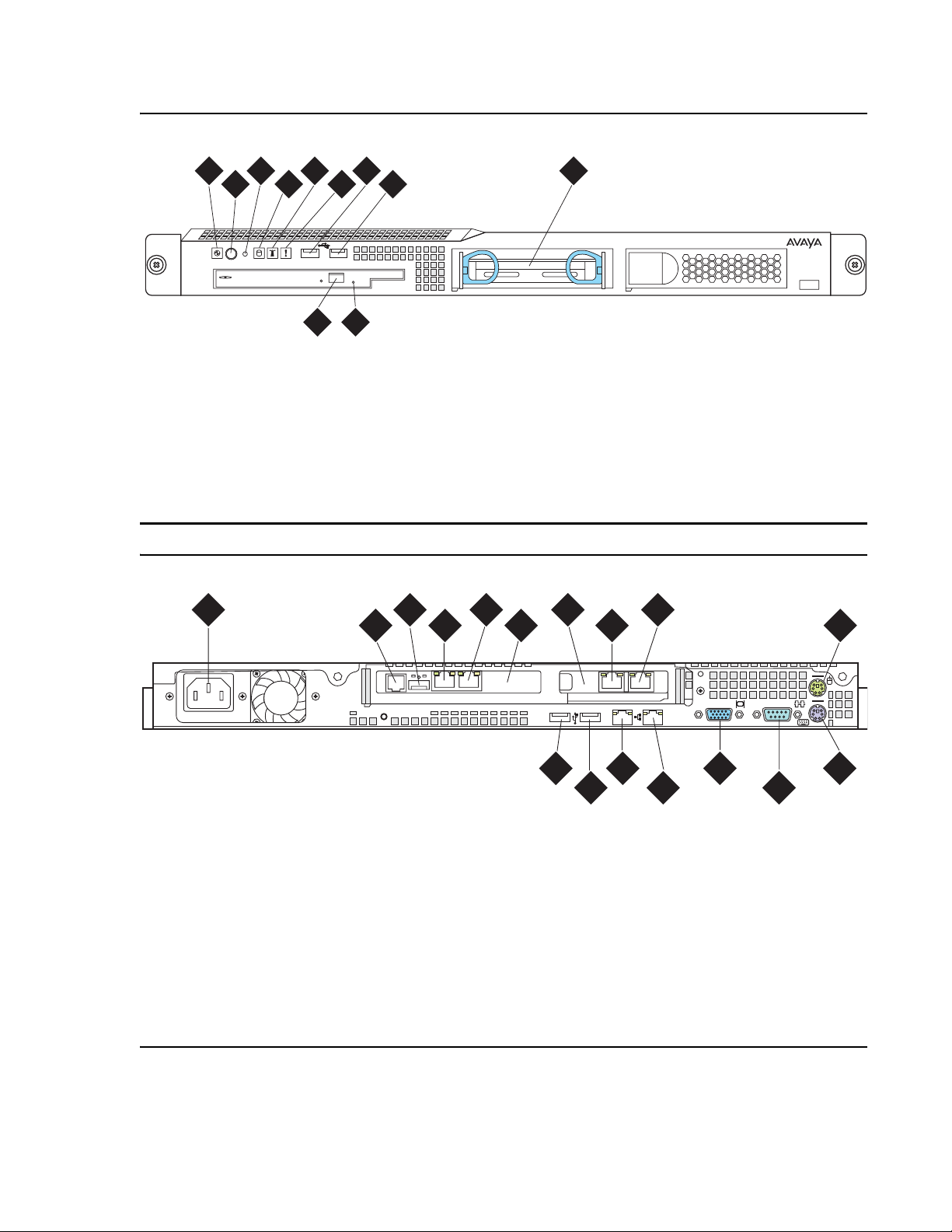
Figure 1: S8500C front panel
S8500 hardware
1
3
2
DVD
CD-RW
5
4
10
6
11
Figure notes:
1. Power-on LED
2. Power button
3. Reset button
4. Hard disk drive activity LED
5. Locator LED
6. System error LED
Figure 2: S8500C back panel
1
7
9
8
h3msf8cc LAO 031706
7. USB port
8. USB port
9. Hard disk drive
10. CD eject button
11. CD-ROM drive activity LED
3
2
5
4
6
7
9
8
10
Slot 1
h2msb8cc LAO 031706
Figure notes:
1. Power cord connector
2. SAMP power
3. USB connection to USB modem
4. Ethernet port (SAMP Eth 1)
5. SAMP Services port (SAMP Eth 2)
6. SAMP card
7. Dual NIC
8. Ethernet 4
9. Ethernet 3
11
12
10. Mouse connector
11. USB port
12. USB port
13. Ethernet 0
14. Ethernet 1
15. Video connector
16. Serial connector
17. Keyboard connector
Slot 2
1
2
13
14 16
1715
Installing and Configuring the Avaya S8500 Media Server February 2007
11
Page 12
Chapter 1: Introduction
6
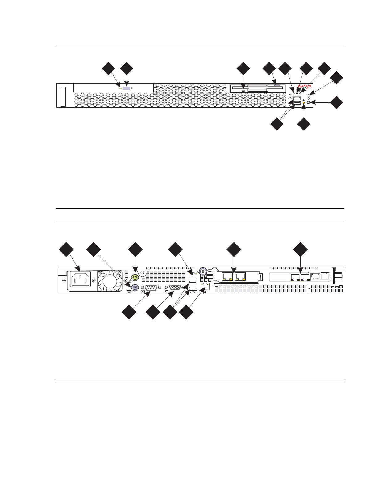
Figure 3: S8500B front panel
21 4
h2ms85bf KLC 091704
Figure notes:
1. CD-ROM drive activity LED
2. CD-ROM eject button
3. Diskette drive activity LED
4. Diskette eject button
5. System error LED
6. System locator LED
7. Hard disk drive activity LED
.
Figure 4: S8500B back panel
3
8. Power on LED
9. Power control button
10. Reset button —
Press to reset the media
5
11
10
6
7
server and run the power-on self-test
(POST).
11. USB connections for the compact flash drive.
8
9
1
Figure notes:
1. Power cord connector
2. Keyboard connector
3. Mouse connector
4. Ethernet port (Eth 0)
5. Dual NIC with Ethernet ports Eth 2 and Eth 3
2
3
7
8 9 10
4
2
6. SAMP card
7. Video connector
8. Serial connector
9. USB ports
10. Ethernet port (Eth 1)
5
6
h2ms85bb LAO 05250
12 Installing and Configuring the Avaya S8500 Media Server February 2007
Page 13

Equipment specifications
The S8500 Media Server control network components consist of the media server, one UPS,
and an Avaya-provided Ethernet switch (optional). The physical specifications for the control
network components are shown in Table 1
Table 1: S8500 control network components specifications
Equipment specifications
.
Component Dimensions
English
(height x width x depth
Media Server:
S8500B
S8500C
Ethernet Switch:
C363T
C364T
UPS:
700 VA
1500 VA
in inches
1.75 x 17 x 20
1.75 x 17 x 22
1.75 x 17 x 14.4
1.75 x 17 x 14.4
3.5 x 17 x 19
3.5 x 17 x 24
)
Dimensions
Metric
(height x width x depth
in centimeters
4 x 43 x 51
4 x 43 x 56
4 x 43 x 37
4 x 43 x 37
9 x 43 x 48
9 x 43 x 61
)
Height
(u)
1
1
1
1
2
2
Weight
(lb/kg)
28/13
11/5
11/5
34/15
50/23
Installing and Configuring the Avaya S8500 Media Server February 2007
13
Page 14

Chapter 1: Introduction
Table 2 outlines the features and specifications of the Avaya S8500 Media Server. The
differences between the S8500B and S8500C versions are noted.
Table 2: S8500 Media Server specifications
Feature S8500B S8500C
Microprocessors
Memory One 512 MB PC2100 CL2.5 ECC DDR
Drives One 80 GB SATA hard disk drive
CPU: 3.0 GHz Pentium (P4)
FSB: 800 MHz front-side bus
SDRAM RDIMM
CD-ROM/DVD-ROM: IDE
CPU: 3.2 GHz Pentium (P4)
FSB: 800 MHz front-side bus
Two 512 MB PC2-4200 CL4 ECC DDR2
SDRAM DIMM
One 80 GB SATA hard disk drive
CD-ROM/DVD-ROM: IDE
Dual NIC Optional One dual NIC card
Slots Two PCI-X slots - 64 bit/66 MHz
Accommodates the SAMP and dual NIC
Power
supply
Integrated
functions
300 W (110 VAC or 220 VAC
autosensing)
Ethernet ports: two 10/1000/100BaseT
Ethernet controllers
Two PCI-X slots - 64 bit/66 MHz
Accommodates the SAMP and dual NIC
350 W (110 VAC or 220 VAC
autosensing)
Same as the S8500B.
One serial port (not used)
Four USB ports (3 not used)
Keyboard port (not used)
Mouse port (not used)
Dual-channel bus mastering IDE
controller
14 Installing and Configuring the Avaya S8500 Media Server February 2007
Page 15

Equipment specifications
Environmental specifications for the S8500 Media Servers are shown in Table 3.
Table 3: S8500 Media Server environmental specifications
Parameter S8500B Specifications S8500C Specifications
Acoustical
Noise
Emissions
Environment:
Air
Temperature
Environment:
Humidity
Heat Output
Electrical
Input
Sound power, idling: 65 decibel maximum
Sound power, operating: 65 decibel
maximum
Media server on:
50.0°F to 95.0°F (10°C to 35°C)
Altitude: 0 ft to 2999 ft (0 m to 914 m)
Media server off:
-40°F to 140°F (-40° to 60° C)
Maximum altitude: 6998 ft (2133 m)
Media Server on: 8% to 80%
Media Server off: 8% to 80%
Minimum configuration: 297 BTU (87 W)
Maximum configuration: 512
Receptacle U.S.: NEMA 5-15 A
Circuit Breaker: 15 A
Sine-wave input (47 Hz to 63 Hz) required
Input voltage low range: 100 – 127 VAC
Input voltage high range: 200 – 240 VAC
Input kilovolt-amperes (approximate):
0.09 – 0.15 kVA
BTU (150 W)
Same as S8500B
Same as S8500B
Same as S8500B
Same as S8500B
Same as S8500B
Same as S8500B
Same as S8500B
Same as S8500B
Minimum configuration: 341
Maximum configuration: 1024
Same as S8500B
Same as S8500B
Same as S8500B
Same as S8500B
Same as S8500B
Input kilovolt-amperes (approximate):
0.10 – 0.55 kVA
BTU (100 W)
BTU (300 W)
Amp draw:
100 to 127 V ~ 4.6 A
200 to 240 V ~ 2.3 A
Installing and Configuring the Avaya S8500 Media Server February 2007
Amp draw:
100 to 127 V ~ 6.0 A
200 to 240 V ~ 3.0A
15
Page 16

Chapter 1: Introduction
About the Server Availability Management Processor
The Server Availability Management Processor (SAMP) remote maintenance circuit card is
preinstalled in the S8500 Media Server. The SAMP monitors and reports alert s from the S8500
components to provide remote maintenance and serviceability for the media server. The SAMP
also provides controls to turn on and turn off the power to the media server.
About SAMP functionality
The SAMP circuit card:
● Monitors the fans, the voltages, and the temperature.
● Reports media-server-failure alarms and other alarms to INADS by way of a modem.
Note:
Note: Modem contention is resolved on a first-come first-serve basis. For example,
Services dials into the SAMP, and the media server must send out an alarm
through the modem interface. Although the modem is busy, the media server
continues to try to send the alarm.
● Provides the capability to turn on power and to reset the media server remotely.
● Provides a secure dial-in connection to the SAMP and the host.
● Provides access to the SAMP and subsequently access to the host by way of the Services
laptop.
The SAMP presents a virtual TTY that the media server uses when the media server must send
out alarms through the modem interface (). The system uses the modem that is connected to
the USB port on the SAMP card to report alarms on the:
● Media server by the media server
● Media server by the SAMP, such as server reboots.
● SAMP by the SAMP
About SAMP connections
The SAMP card is installed in PCI-X slot 1 of the Avaya S8500 Media Server. Slot 1 is a
full-height, three-quarters length slot.
The SAMP comes in a half-card PCI form factor and is po wered externally. The SAMP supports
one USB interface and two 10/100 Ethernet ports that are located on the rear of the media
server.
16 Installing and Configuring the Avaya S8500 Media Server February 2007
Page 17
About the Server Availability Management Processor
● SAMP Ethernet 1 is not used.
● SAMP Ethernet 2 is for local access. This port is for on-site services personnel to access
the SAMP with the craft login.
● The USB interface is used to connect a USB modem for remote dial-in and dial-out
access. The media server and the SAMP share this modem connection for remote
maintenance, administration, and alarming. For remote dial-in, the user first establishes a
Point-to-Point Protocol (PPP) session that terminates at the SAMP. The user can then use
the craft login to establish an SSH (Secure Shell) or an HTTPS (Secure Web) session to
the SAMP or the host.
The SAMP also communicates with the host in-band by way of an on-board industry-standard
Ethernet controller on the PCI bus of the host with an internal link to the SAMP.
Figure 5: SAMP connections for S8500B
shows the locations of the connections on the SAMP
for the S8500B. Figure 5: SAMP connections for S8500B
the connections on the SAMP for the S8500C.
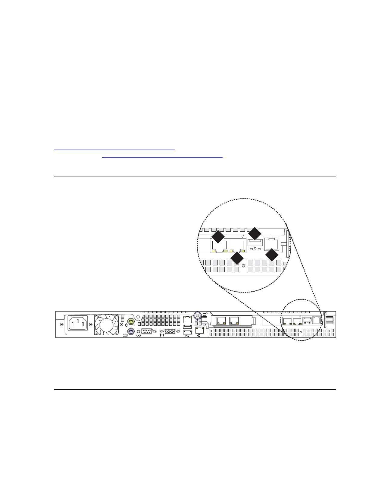
Figure 5: SAMP connections for S8500B
1
on page 17 shows the locations of
3
2
4
2
h2ms85bs LAO 051706
Figure notes:
1. SAMP Eth2—to the services laptop
computer (cross-connect CAT5 cable)
2. SAMP Eth1 (not used)
Installing and Configuring the Avaya S8500 Media Server February 2007
3. USB connection for the modem
4. External power to the SAMP
17
Page 18
Chapter 1: Introduction
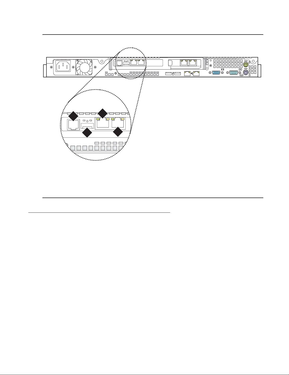
Figure 6: SAMP connections for S8500C
Slot 1
4
2
3
Figure notes:
1. SAMP Eth2—to the services laptop
computer (cross-connect CAT5 cable)
2. SAMP Eth1 (not used)
Slot 2
1
2
h2ms85cs LAO 051906
1
3. USB connection for the modem
4. External power to the SAMP
About SAMP software
The SAMP is shipped from the factory with the software installed and with some default
settings. However, you might need to install an updated version of the software, and you must
configure the SAMP before you can use it.
If a SAMP software update file is available on the Avaya Support website, one of the
preinstallation tasks required that you load the file on your laptop: see Using the Avaya Server
Availability Management Processor (SAMP) (03-300322) for how to install software on the
SAMP and change the default settings.
18 Installing and Configuring the Avaya S8500 Media Server February 2007
Page 19
About media server port connections
2
1
The following section explains how to connect the Ethernet ports on the back of the media
server.
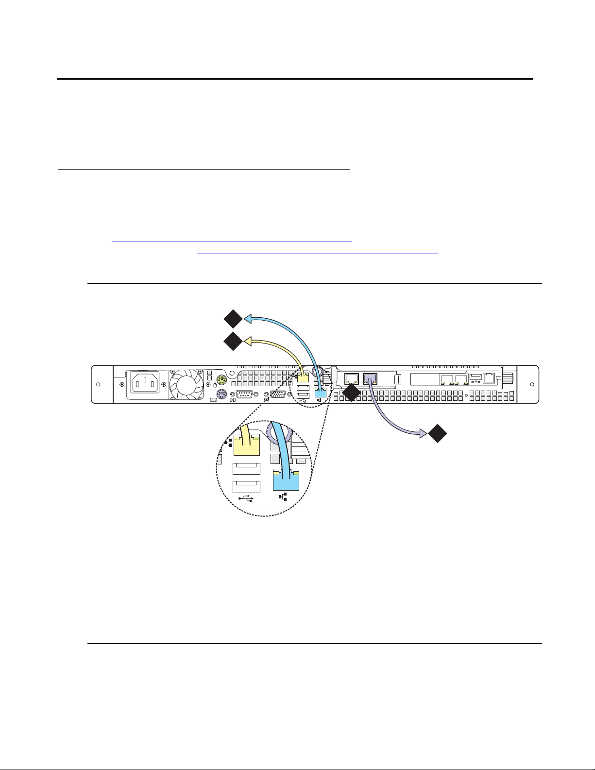
S8500 port connections
Use standard CAT5 cables with RJ45 connectors on each end to connect to the various port s. If
the S8500 Media Server has only one port network, connect that port network through the dual
NIC. Figure 7: S8500B Media Server connectivity guide
S8500B Media Server. Figure 8:
S8500C Media Server connectivity guide on page 20 shows
typical connectivity for the S8500C Media Server.
Figure 7: S8500B Media Server connectivity guide
2
shows typical connectivity for the
About media server port connections
1
Figure notes:
1. Eth0—To the customer network if the
control network is shared. Or, to the
control-network Ethernet switch if the
control network is dedicated
(straight-through CAT5 cable)
2. Eth1—To the Services laptop computer
(cross-over CAT5 cable)
1
4
2
3. Eth2—to the customer network if the
control network is dedicated
(straight-through CAT5 cable)
4. Eth3—Not used
h3msbl5d LAO 052506
3
Installing and Configuring the Avaya S8500 Media Server February 2007
19
Page 20
Chapter 1: Introduction
2
1
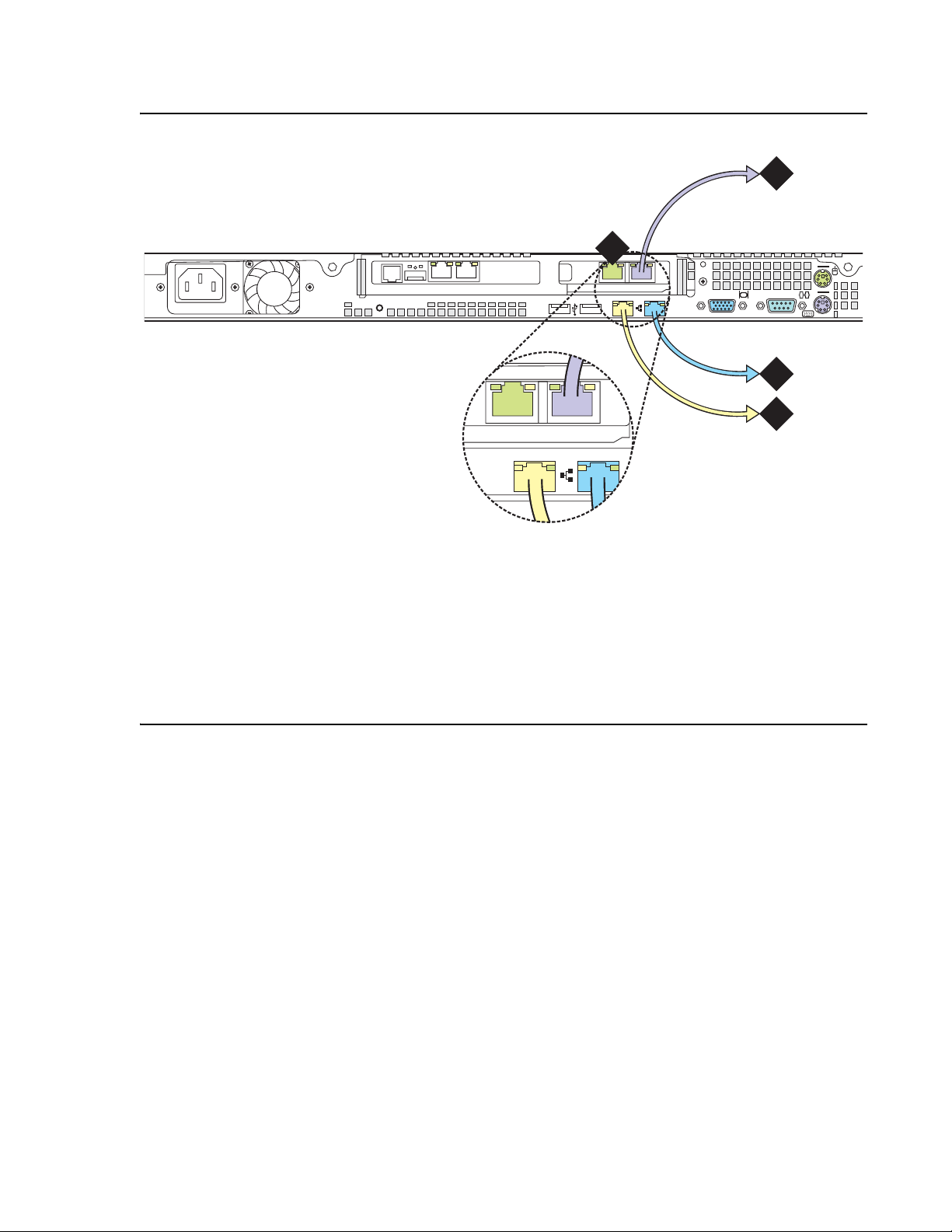
Figure 8: S8500C Media Server connectivity guide
2msb8cp LAO 052506
Slot 1
3
4
Slot 2
1
2
2
1
Figure notes:
1. Eth0—To the customer network if the
control network is nondedicated. Or, to
the control-network Ethernet switch if the
control network is dedicated
3. Eth3—to the customer network if the
control network is dedicated
(straight-through CAT5 cable)
4. Eth4—Not used
(straight-through CAT5 cable)
2. Eth1—To the Services laptop computer
(cross-over CAT5 cable)
Note:
Note: If the S8500C is configured as an ESS, the port assignments are different:
● Eth0: Control Network A
● Eth3: Control Network B
● Eth4: LAN, if two dedicated control networks are used
In either case, ETH2 is an internal port dedicated to the SAMP.
20 Installing and Configuring the Avaya S8500 Media Server February 2007
Page 21
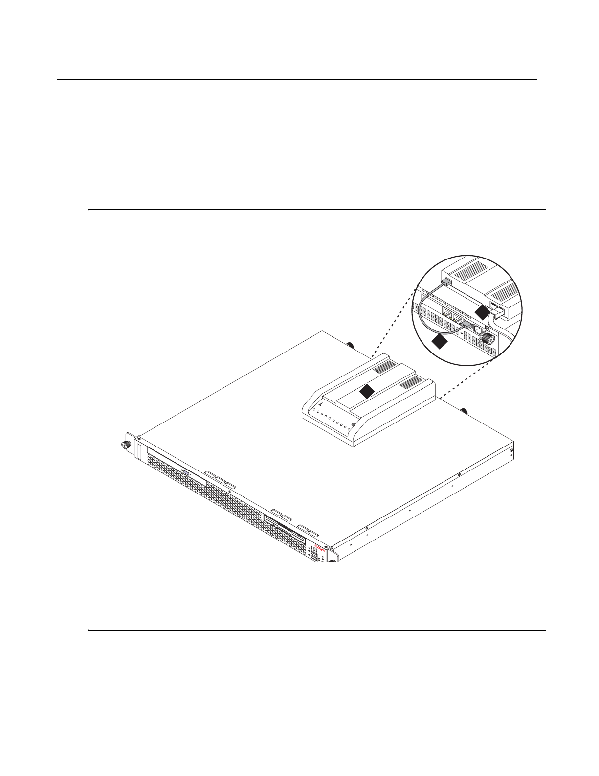
About modem connections
Note:
Note: You cannot connect USB modems to rotary lines. A touch tone line is required.
On an Avaya S8500 Media Server, connect the modem to the USB port on the SAMP.
Avaya defaults on the SAMP set the required options on the SAMP modem. For modem
connectivity, see Figure 9: Modem connectivity on the S8500 Media Server
Figure 9: Modem connectivity on the S8500 Media Server
About modem connections
.
3
d
is
c
Figure notes:
1. Modem
2. USB cable that connects the USB modem
to the USB port on the media server
2
1
Multi
Modem
MultiTech
S
oftw
are
3. Telephone line that connects th e modem
to the outside line
Installing and Configuring the Avaya S8500 Media Server February 2007
21
Page 22

Chapter 1: Introduction
Modem options
You set the modem options when yo u configure the media se rver. You do not set options on the
modems themselves.
About media gateways
In a new installation, the Avaya S8500 Media Server works with only the Avaya G650 Media
Gateway.
In a migration, the media server works with the following Avaya media gateways:
● SCC1
● G600
● CMC1
The media servers also work with Avaya G150, G250, G350, and G700 Media Gateways.
These gateways register with the media server either through the Processor Ethernet interface
or through a TN799DP C-LAN circuit pack.
With an S8500 Media Server, these media gateways can be endpoints that use a Processor
Ethernet interface.
Media gateways usually are installed in the same equipment room as the media server rack
hardware or control network. However, you can install the media gateways in another location,
including another state or country.
About Processor Ethernet
Like a C-LAN circuit pack, Processor Ethernet provides conn ectivit y to IP en dpoints, gateways,
and adjuncts. The PE interface is a logical connection in the Communicat ion Manager sof tware
that uses a port on the NIC in the server. No additional hardware is needed to implement PE.
St arting with Release 3.1 of Communicat ion Manager, the PE interface is enabled on the S8500
Media Server to allow enhanced flexibility to connect to gateways, endpoints, and adjuncts.
22 Installing and Configuring the Avaya S8500 Media Server February 2007
Page 23

About Processor Ethernet
.Table 4 lists the possible uses of the PE interface for an S8500 primary controller.
Table 4: Use of the PE interface for a simplex S8500 primary controller
Possible functions of
the PE interface
Status of the function
on the S8500 Media
Server
Registration The PE interface is
enabled for registration
on a simplex main server.
H.248 gateway
registration
H.248 gateway
registration is allowed on
the S8500 main server
using the PE interface.
H.323 endpoint
registration
H.323 registration is
allowed on the S8500
main server using the PE
interface.
Adjunct connectivity Adjunct connectivity is
allowed on the S8500
main server using the PE
interface.
Administration needed?
No. The Communication Manager
software automatically enables the
use of the PE interface for
registration.
Yes. You perform the administration
to allow H.248 registration on the PE
interface of the S8500 main server on
the ip-interfaces procr form.
Yes. You perform administration to
allow H.323 registration of the PE
interface of the S8500 main server on
the ip-interfaces procr form.
Y es. To administer adjuncts, you must
use the ip-services form or the
communication-interface
processor-channels form before the
survivable-processor form.
Installing and Configuring the Avaya S8500 Media Server February 2007
23
Page 24

Chapter 1: Introduction
About S8500 LSP mode
Starting with Release 3.1 of Communication Manager, you can configure the S8500 as a local
survivable processor (LSP), and, the S8500 can be the primary controller for an IP network with
port networks. This new functionality is enabled by allowing H.248 gateways and H.323
endpoints to use the Processor Ethernet (PE) interface of the S8500 instead of a C-LAN
interface to register with the S8500.
Table 5
Table 5: Use of the PE interface on the S8500 LSP
lists the possible uses of the PE interface for an S8500 LSP.
Possible
functions of
the PE
interface
Registration The PE interface is
H.248 gateway
registration
H.323 endpoint
registration
Status of the function
on the LSP server
always enabled for
registration.
H.248 gateway
registration is enabled by
default.
H.323 endpoint
registration is enabled by
default.
Administration needed
No. The Communication Manager software
automatically enables the use of the PE
interface for registration.
No. The H.248 gateway enabled field on the
ip-interface procr form defaults to yes on an
LSP. To temporarily disable H.248 registration
on the LSP, you can change the ip-interfaces
procr form on the LSP. Any change that you
perform on the LSP is lost when the LSP
receives a file sync from the main server. Af ter
a file sync H.248 gateway registration will
default to yes.
No. The H.248 gateway enabled field on the
ip-interface procr form defaults to yes on an
LSP. To temporarily disable H.248 registration
on the LSP, you can change the ip-interfaces
procr form on the LSP. Any change that you
perform on the LSP is lost when the LSP
receives a file sync from the main server. Af ter
a file sync, H.248 gateway registration
defaults to yes.
Adjunct
connectivity
Adjunct connectivity is
enabled by default.
Yes. You must perform adjunct administration
for the LSP on the main server.
24 Installing and Configuring the Avaya S8500 Media Server February 2007
Page 25

The PE interface on an S8500 LSP supports three adjuncts:
● Call Management System (CMS)
● Application Enablement Services (AESVCS)
● Call Detail Recording (CDR)
The S8500 as a primary controller can connect to gateways and endpoints that use both
C-LANs and the PE interface. The traffic over these interfaces can be load balanced.
S8500 LSP license file
The license file for an LSP must have the following attributes:
● The Local Survivable Processor (FEAT_LSP) field is set to y.
● A Module ID (MID) that is greater than 1. This value is set by the license file and cannot be
administered in Communication Manager.
S8500 LSP license file
● A System ID (SID). The SID is unique to the system configuration. The primary controller
and all LSPs have the same SID.
● The serial number of an H.248 media gateway to serve as the license serial number host.
During initial installation, when the LSP server is reset, the LSP sends this serial number to
the primary controller. The primary controller then matches the serial number to the serial
number of an existing media gateway. The primary controller sends the IP address of the
media gateway back to the LSP. T o verify th e license, the LSP can then contact that media
gateway and request the serial number. The LSP compares the serial number from the
media gateway with the serial number from the license of the LSP.
About SSH
Secure Shell (SSH) is both a computer program and an associated network protocol that you
use to log in to and run commands on a networked computer. SSH provides secure encrypted
communications between two untrusted hosts over an insecure network. Avaya strongly
recommends that you use SSH instead of Telnet for most interactive connections to the Avaya
media servers and other devices on a customer network.
To use SSH, a third-party SSH client must be installed on your computer. PuTTY is one such
client. You can download PuTTY from http://www.putty.nl/download.html
.
Installing and Configuring the Avaya S8500 Media Server February 2007
25
Page 26

Chapter 1: Introduction
You can use SSH to access the following devices:
● The S8300, S8400, S8500, and S8700-series Media Servers on Release 3.1 or later of
Communication Manager
Note:
Note: With Release 4.0 or later of Communication Manager, Telnet is disabled, so you
must use SSH to access the media servers after Communication Manager
software Release 4.0 or later is installed.
● A Server Availability Management Processor (SAMP), which is used with the S8500 Media
Server
● A Maintenance Processor Complex (MPC), which is used with the S8400 Media Server
● A TN2312BP IPSI that is running firmware version 20 or higher
● A TN8412AP SIPI
● A TN2602 IP Media Resource 360 that is running firmware version 212 or higher
● An Expanded Meet-Me Conferencing (EMMC) server
● A SIP Enablement Services (SES) server
● G250 and G350 media gateways
● C360 Ethernet switches
!
Important:
Important: You cannot use SSH with the G700. From within the Linux command line of a
media server, you can use SSH to access the G250 and the G350, but you must
use Telnet to access the G700.
26 Installing and Configuring the Avaya S8500 Media Server February 2007
Page 27

Configuring the SNMP modules in the UPS
Chapter 2: SNMP Configuration
After you install and connect the control network equipment, you must configure the SNMP
modules in each Avaya-supplied UPS to send alarms or traps to the media servers. This
process requires that you also configure the SNMP subagent in the Avaya-supplied Ethernet
switch.
!
Important:
Important: Use the procedures in this section to configure Avaya-supplied equipment only.
Configuring the SNMP modules in the UPS
!
Important:
Important: These procedures apply only to a new, Avaya-supplied uninterruptible power
supply (UPS) with a Simple Network Management Protocol (SNMP) module. Do
not use these procedures to set traps on a UPS that Avaya does not supply.
You must configure the SNMP module in the UPS to report alarms to the media server when
hardware problems occur. The module reports an alarm if commercial power is lost or battery
resources are depleted.
For the SNMP module to properly report alarms, you must configure a unique IP address f or the
UPS on both the SNMP module and the media server. This IP address can be a
customer-provided address or the Avaya-provided default address. At a minimum, you must
configure the following items:
● The IP address
● The subnet mask
● The gateway IP address
● The trap receiver IP address
● The community string (get, set, trap)
A third party manufactures the SNMP module. The brand, the model, o r the firmware load of the
module that Avaya supplies can change without notice. For this reason , this document does not
provide specific instructions on how to connect to and configure the SNMP module. For more
information, see the documentation that comes with the SNMP module. For the default
password and the configuration commands, see the local configuration section of that user
guide.
Installing and Configuring the Avaya S8500 Media Server February 2007
27
Page 28

Chapter 2: SNMP Configuration
Default IP addresses for the UPS
The following table shows the default IP addresses for the UPS.
IP address for the UPS 198.152.254.239
Subnet mask for the UPS 255.255.255.0
Gateway address for the UPS 198.152.254.201
IP address for the
Customer provided
trap receiver (media server)
For how to administer the SNMP module in the UPS, see Administering the SNMP module
page 29.
Prerequisites for configuring the SNMP module
Before you configure the SNMP module, you must complete the following prerequisites:
● Your Services laptop computer is plugged into the correct administration port on the SNMP
module.
● The UPS is plugged into a nonswitched electrical outlet.
● The communication protocol on your computer has the following port settings so that you
can use your terminal emulation program:
-
9600 baud
-
No parity
-
8 data bits
-
1 stop bit
on
-
No flow control
Note:
Note: Avaya Terminal Emulation and HyperTerminal are supported terminal emulation
applications.
● If a Network Management System (NMS) is to monitor the UPS, you coordinated the
assignment of community names with the network administrator. If an NMS is not used,
you set the community names to unique string values.
28 Installing and Configuring the Avaya S8500 Media Server February 2007
Page 29

Configuring the SNMP modules in the UPS
!
!
SECURITY ALERT:
SECURITY ALERT: The Get and Set community name strings are initially configured with the default
values of Public and Private, respectively. These community name strings
function as passwords for their respective SNMP operation. Avaya recommends
that you change these community name strings to something other than the
default values. If you leave the defaults in place, a serious security issue can
result.
For information about which traps to set, see Setting selected traps (alarming)
● If the control network is nondedicated, ensure that the 162/udp port for input to server is
enabled and the default is disabled. If you do not enable the 162/udp port and disable the
default, the media server cannot receive the traps from either UPS. See Enabling firewall
settings on page 44.
Administering the SNMP module
Note:
Note: Use the default IP addresses.
1. Connect the RS-232 serial port of your Services laptop computer to the DB-9 connector on
the back of the SNMP module for UPS1. Use the DB-9 to DB-9 serial cable that is supplied
with the SNMP module.
2. Open a VT-100 terminal emulation session on your computer.
3. Set the IP address for the UPS.
4. Set the subnet mask for the UPS.
5. Set the gateway address for the UPS.
6. Set the IP address of the trap receiver for the UPS.
on page 30.
7. Set the SNMP community name string for Get, Set, and Trap. For information on which
traps to set, see Setting selected traps (alarming)
on page 30.
8. When you finish, disconnect your computer from the UPS.
9. Connect one end of a CAT5 straight-through cable to the RJ45 connector on the UPS
SNMP module and the other end of the cable to the next available port on the Ethernet
switch for Control Network A (CNA).
For a connectivity guide, see the Quick Start for Hardware Installation: Avaya S8500
Media Server (555-245-701).
After you configure the SNMP module in the UPS, you must configure the SNMP subagent on
the Avaya Ethernet switch.
Installing and Configuring the Avaya S8500 Media Server February 2007
29
Page 30

Chapter 2: SNMP Configuration
Setting selected traps (alarming)
The default is to set all traps, which can result in large log entries. To avoid this problem, Avaya
recommends that you set only the following traps:
● UPS on Battery—Indicates an AC power failure. Based on the level of battery reserve, a
shutdown is pending.
● UPS in Bypass—The UPS failed or is overloaded.
● Replace battery—The battery failed the 28-day battery test and must be replaced.
For the menus and commands to set these traps, see the user guide that comes with the SNMP
module.
Configuring the SNMP subagent in the Avaya Ethernet switch (if used)
!
Important:
Important: These procedures apply only to a new, Avaya-supplied uninterruptible power
supply (UPS) with a Simple Network Management Protocol (SNMP) module. Do
not use these procedures to set traps on a UPS that Avaya does not supply.
You must administer the Simple Network Management Protocol (SNMP) subagent in the A vaya
Ethernet switch to report alarms to the media server when problems occur.
For the SNMP module to properly report alarms, you must configure a unique IP address f or the
UPS on both the SNMP module and the media server. This IP address can be a
customer-provided address or the Avaya-provided default address. At a minimum, you must
configure the following items:
● The IP address
● The subnet mask
● The gateway IP address
● The trap receiver IP address
● The community string (get, set, trap)
The brand, the model, or the firmware load of the Ethernet switch that Avaya supplies can
change without notice. For this reason, this document does not provide specific instructions on
how to connect to and configure the SNMP subagent. For more information, see the
documentation that comes with the Ethernet switch. Also see the Basic Configuration section of
the Quick Start Guide and the documentation CD-ROM that comes with the Ethernet switch for
the default user ID, password, and configuration commands.
30 Installing and Configuring the Avaya S8500 Media Server February 2007
Page 31

Configuring the SNMP subagent in the Avaya Ethernet switch (if used)
Note:
Note: For the Ethernet switch to report alarms properly, you must also configure the IP
addresses for the Ethernet switches in the media servers.
Default IP addresses for the Ethernet switch
The following table shows the default values for the Ethernet switch.
Parameter Single control
network (CNA)
IP address for the Ethernet switch 198.152.254.240 198.152.255.240
Subnet mask for the Ethernet switch 255.255.255.0 255.255.255.0
IP address for the
Customer provided Customer provided
trap receiver (media server)
For how to administer the SNMP subagent in the Ethernet switch, see Co nfiguring the Et hernet
switch on page 32.
Preparing to configure the Ethernet switch
Before you configure the Ethernet switch, you must complete the following prerequisites:
● The Ethernet switch power cord is connected to the back of the switch and to the back of a
UPS.
● The communication protocol on your computer has the following port settings so that you
can use your terminal emulation program:
Duplicated control
network (CNB)
-
9600 baud
-
No parity
-
8 data bits
-
1 stop bit
-
No flow control
Note:
Note: Avaya Terminal Emulation and HyperTerminal are supported terminal emulation
applications.
● If a Network Management System (NMS) is to monitor the Ethernet switch, you
coordinated the assignment of community names with the network administrator. If an
NMS is not used, you set the community names to unique string values.
Installing and Configuring the Avaya S8500 Media Server February 2007
31
Page 32

Chapter 2: SNMP Configuration
!
!
SECURITY ALERT:
SECURITY ALERT: The Get and Set community name strings are initially configured with the default
values of Public and Private, respectively. These community name strings
function as passwords for their respective SNMP operation. Avaya recommends
that you change these community name strings to something other than the
default values. If you leave the defaults in place, a serious security issue can
result.
● If the control network is not dedicated, ensure that the 162/udp port for input to server is
enabled and the default is disabled. If you do not enable the 162/udp port and disable the
default, the media server cannot receive the traps from either UPS. See Enabling firewall
settings on page 44.
Configuring the Ethernet switch
Note:
Note: Use the default addresses.
1. Connect the RS-232 serial port of your Services laptop computer to the port labeled
Console on the front of Ethernet switch 1 (CNA). Use the flat cable supplied with the Avaya
Ethernet switch.
2. Open a VT-100 terminal emulation session on your computer.
3. Set the IP address for the Ethernet switch.
4. Set the subnet mask for the Ethernet switch.
5. Set the gateway IP address for the Ethernet switch.
6. Set the IP address of the trap receiver for the Ethernet switch.
7. Set the SNMP community name string for Get, Set, and T rap. For information about setting
these values, see the section on SNMP commands on the documentation CD-ROM that
comes with the Avaya Ethernet switch.
8. Use the command set spantree enabled to verify that spanning tree is enabled. Note
that enabled is the default setting.
9. Use the command set spantree version rapid-spanning-tree to set the
spanning tree version to rapid-spanning-tree. Do not use the default.
Note:
Note: This command is available on Avaya Ethernet switches with firmware version 4.0
or later. To use this command, you must update the firmware to this version, if
necessary.
For more information on the spanning tree CLI commands, see Installation and
Configuration Guide, Avaya C360 and Reference Guide, Avaya C360. These documents
are available at the Avaya Support Web site http://www.avaya tha.com/suppor t
.
32 Installing and Configuring the Avaya S8500 Media Server February 2007
Page 33

Configuring the SNMP subagent in the Avaya Ethernet switch (if used)
10. If the port networks are IP-PNC, ensure that all appropriate ports on the Ethernet switch
are locked to 100 speed and full duplex.
11. When you finish, disconnect your computer from the Ethernet switch.
12. If two Ethernet switches are present for CNA, repeat Steps 1 through 10 for the second
switch.
Installing and Configuring the Avaya S8500 Media Server February 2007
33
Page 34

Chapter 2: SNMP Configuration
34 Installing and Configuring the Avaya S8500 Media Server February 2007
Page 35

Clearing the ARP cache on the laptop
Chapter 3: Communication Manager
inst allation
A new media server comes with a blank hard disk drive. Use the bootable software distribution
CD-ROM to install the Linux operating system and Avaya Communication Manager.
This chapter covers the following tasks:
● Clearing the ARP cache on the laptop on page 35
● Applying power to the media server on page 36
● Accessing the media server on page 36
● Configuring Telnet for Windows 2000 and Windows XP on page 36
● Installing Avaya Communication Manager on page 37
!
Important:
Important: If you are installing an S8500B Media Server to run the Expanded Meet-me
Conferencing (EMMC) application, follow the installation instructions in this
document up to and including . Then use the Expanded Meet-me Conferencing
(EMMC) version 1.0 Installation and Troubleshooting Guide, (04-300527) to
complete the installation of the EMMC. The two CD-ROMs EMMC Software Disk
1 and EMMC Software Disk 2 contain the EMMC software.
Clearing the ARP cache on the laptop
Depending on the operating system of your Services laptop computer, you might need to clear
the Address Resolution Protocol (ARP) cache before you enter a new IP address. If you enter
an IP address and your computer cannot connect, perform the following procedure to clear the
cache.
1. On your computer, click Start > Run to open the Run dialog box.
2. Type command and press Enter to open an MS-DOS command line window.
3. Type arp -d 192.11.13.6 and press Enter to clear the ARP cache in the laptop.
If the ARP cache does not contain the specified IP address, the message The specified
entry was not found appears. You can ignore this message.
4. Type exit and press Enter to close the command line window.
Installing and Configuring the Avaya S8500 Media Server February 2007
35
Page 36

Chapter 3: Communication Manager installation
Applying power to the media server
Note:
Note: In this procedure, the software CD-ROM must be placed into the CD-ROM drive
on the media server immediately after you turn on the power to the media server.
1. Connect the AC power cord to the media server and to the UPS or a nonswitched
electrical outlet.
2. If the media server does not turn on, press the white power control button on the front of
the media server.
3. Immediately place the Avaya Communication Manager CD-ROM into the CD-ROM drive
on the media server. Or, If you are installing an S8500 Media Server to run the Expanded
Meet-me Conferencing (EMMC) application, use the CD-ROM that is labeled EMMC
Software Disk 1.
Accessing the media server
1. Use a cross-over cable to connect your laptop computer to the Services port on the back
of the media server. The Services port is labeled "2" and is configured as Eth1.
2. Wait at least 3 minu tes after you turn on the media server before you start a Telnet session
to access the information on the CD-ROM.
Configuring Telnet for Windows 2000 and Windows XP
The Microsoft Telnet application might be set to send a carriage return (CR) and a line feed (LF)
whenever you press Enter. The Communication Manager installation program sees this as two
key presses. If you are running Windows 2000 or Windows XP, you must correct this setting
before you copy the Remaster Program to the hard disk drive.
1. Click Start > Run to open the Run dialog box.
2. Type telnet and press Enter to open a Microsoft Telnet session.
3. Type unset crlf and press Enter.
4. Type display and press Enter to verify that you see the message Line feed mode -
Causes return key to send CR.
5. Type q and press Enter to exit the telnet session.
36 Installing and Configuring the Avaya S8500 Media Server February 2007
Page 37

Installing Avaya Communication Manager
Installing Avaya Communication Manager
Use a Telnet session to access the information on the CD-ROM.
1. On your Services laptop computer, click Start > Run to open the Run dialog box.
2. Type telnet 192.11.13.6 and press Enter to view the first screen.
Note:
Note: To navigate on these screens, use the arrow keys to move to an option, and then
press the spacebar to select the option. Press Enter to submit the informatio n on
the screen.
3. Select Install, ensure that <OK> is highlighted, and press Enter.
4. On the Select Release Version screen, ensure that the Build line and <OK> are
highlighted. Press Enter to partition the hard disk drive and reformat the partitions.
Once the drive is properly configured, the program starts the installation process and
reports the progress.
These processes can take up to 20 minutes to complete.
5. You must remove the CD-ROM from the drive at t his time. When the media server is ready
to reboot, the drawer of the CD-ROM drive opens.
The reboot can take up to 3 minutes. The Telnet session drops automatically when the
reboot starts.
6. Perform one of the following actions:
● If you are installing the S8500 Media Server as a call controller, continue with the next
section of this document.
● If your are installing the S8500 as an LSP, continue with Chapter 7: Install an S8500
Media Server as an LSP on page 63.
Installing and Configuring the Avaya S8500 Media Server February 2007
37
Page 38

Chapter 3: Communication Manager installation
● If you are installing an S8500 Media Server to run the Expanded Meet-me
Conferencing (EMMC) application, you are finished with this document. Continue the
EMMC installation procedures described in Installing and Troubleshooting the
Expanded Meet-me Conferencing (EMMC) (04-300527).
38 Installing and Configuring the Avaya S8500 Media Server February 2007
Page 39

Chapter 4: Media server configuration
After you install the Communication Manager software, you must use the Avaya Installation
Wizard to configure the media server.
This section covers the following tasks:
● Copying files to the media server on page 40
● Creating a super-user login on page 40
● Running the Avaya Installation Wizard on page 42
● Verifying the RMB IP information on page 42
● Installing SAMP firmware on page 42
● Verifying the media server connection to the customer LAN (if provided) on page 43
● Enabling firewall settings on page 44
● Enabling network time servers on page 44
● Checking LED activity on the dual NIC on page 46
● Configuring the NIC on page 46
Note:
Note: Ensure that you have the completed Electronic Preinstallation Worksheet (EPW)
before you start this process.
Note:
Note: Ensure that your networking and Web browser settings are correct. For more
information, see Configuring the network for Windows 2000 and XP
on page 94.
Installing and Configuring the Avaya S8500 Media Server February 2007 39
Page 40

Chapter 4: Media server configuration
Opening the Maintenance Web Interface
You can use the Maintenance Web Interface to copy license files and authentication files,
service packs, and SAMP update files from the Services laptop to the media server. For how to
open the Maintenance Web Interface, see Accessing the Maintenance Web Interface
page 92.
Copying files to the media server
1. From the Maintenance Web Interface, under Miscellaneous, click Download Files.
2. Select File(s) to download from the machine I’m using to connect to the server.
3. Click Browse next to the top field to open the Choose File window on your computer. Find
the files that you need to copy to the media server.
on
4. Click Download to copy the files to the media server.
The files are automatically copied to the default file location.
Creating a super-user login
Note:
Note: A craft level login can create the super-user login in Release 4.0 or later.
Make sure you have a login name and password t hat the customer would like for th e superuser
login. If you are a business partner, you can also repeat this procedure to add the dadmin login.
To create a login:
Note:
Note: Make sure the customer can change this login, its password, or its permissions
later.
1. Under Security, select Administrator Accounts.
2. Type the login name in the Enter Login ID or Group Name field.
3. Select Add Login, and click Submit.
4. Type susers in the login group field.
5. Type prof18 in the additional groups field. prof18 is the code for the cust omer superuser.
40 Installing and Configuring the Avaya S8500 Media Server February 2007
Page 41

About the Avaya Installation Wizard
6. Put a check in the allow Linux shell access field.
7. Skip the lock this account and date on which account is disabled fields.
8. For the select type of authentication option, select password.
9. Complete the following fields:
● enter key or password
● re-enter key or password
● force password/key change on first login
Note:
Note: Do not lock the account or set the password to be disabled.
10. Leave the defaults in the remaining fields.
11. Click Add.
The system tells the login is added successfully.
About the Avaya Installation Wizard
Use the Avaya Installation Wizard to automatically:
● Configure the media server
● Configure the Remote Maintenance Board
● Install the license file
Note:
Note: To install the license file the server does not have to be connected to the
reference IPSI. However , you have only 30 minutes before the system checks the
serial number on the IPSI. To add another 30 minutes, type reset system 1
and press Enter in a SAT session to restart the Communication Manager
software.
● Install the Avaya authentication files
● Install software updates
To use the Installation Wizard, you can either:
● Import the data from the completed Electronic Preinstallation Worksheet (EPW). When the
Installation Wizard prompts you to import the Preinstallation Worksheet, click Import EPW
and browse to the location of the EPW file on your Services laptop computer. The
Installation Wizard opens the EPW and uploads the configuration data.
● Type the information manually with the completed EPW as a guide. The Installation Wizard
prompts you to enter the configuration data for each step in the Configure Server section.
Installing and Configuring the Avaya S8500 Media Server February 2007
41
Page 42

Chapter 4: Media server configuration
Running the Avaya Installation Wizard
1. With the Web browser open, type 192.11.13.6 and press Enter in the browser address
window to display the login page.
2. Log in as craft and use the initial craft password.
3. Click Launch Avaya Installation Wizard.
4. Follow the prompts. For more information use Help on each page.
Verifying the RMB IP information
The Remote Maintenance Board (RMB) page is under Optional Services in the Installation
Wizard configuration process. Verify that the Installation Wizard retrieved the IP information
from the EPW. If the information is not there, complete all fields manually.
To allow Services access to the remote maintenance board through a cross-over cable, verify
the information in the following fields:
● IP Address 192.11.13.6
● Subnet Mask 255.255.255.252
If the information is not there, complete the fields manually.
Installing SAMP firmware
You might need to update the SAMP firmware if the most current version is not installed.
Information about the versions that require updates should be included in your pro ject pla nnin g
information.
For how to update SAMP software, see Using the Avaya Server Availability Management
Processor (SAMP).
1. Check the firmware version:
a. Use SSH to access the media server and log in.
b. Type sampcmd samp-update status and press Enter.
c. Check the firmware version displayed.
2. If you need to update the firmware, from the Maintenance Web Interface under
Miscellaneous, click Download Files.
42 Installing and Configuring the Avaya S8500 Media Server February 2007
Page 43

Verifying the media server connection to the customer LAN (if provided)
3. Enter the information to copy the firmware file to the media server.
4. Use SSH to access the media server and log in.
5. To start the update process, type sampupdate and press Enter.
The update process takes approximately 5 minutes.
Verifying the media server connection to the customer
LAN (if provided)
1. From the Maintenance Web Interface, under Diagnostics, click Ping.
2. Select Host Name Or IP Address and type the IP address of a computer on the network.
3. Click Execute Ping.
4. V erify that the ping was successful and indicates that the media server is connected to the
customer network.
5. If DNS is administered, type the host name of a computer on the network.
6. Click Execute Ping.
7. Verify that the ping was successful and indicates that DNS is working.
If possible, have a customer representative perform the following test from a computer on the
network:
1. Click Start > Run to open the Run dialog box.
2. Type command and click OK to open an MS-DOS command window.
3. Type ping serveripaddress and press Enter, where serveripaddress is the IP
address of the media server.
4. Verify that the ping was successful.
5. If DNS is administered, type ping servername and press Enter, where servername is
the host name of the media server.
6. Verify that the ping was successful.
Configuring the modem
1. From the Maintenance Web Interface, under Server Configuration click Configure Server.
2. Click Continue until you get to the Specify how you want to use this wizard page.
Installing and Configuring the Avaya S8500 Media Server February 2007
43
Page 44

Chapter 4: Media server configuration
3. Select Configure individual services and click Continue.
4. On the menu on the left, click Set Modem Interface.
5. Select Change Modem Setting and click Continue.
6. In the Extra Modem Initialization Commands window , type the initialization commands that
are appropriate for your modem and the country of operation. Click Help for help on what
to enter.
For example, to change the country code to Japan, type AT%T19,0,10.
7. Click Change.
The system displays a message that indicates that a modem route was added
successfully.
8. Click Close Window.
Enabling firewall settings
For the media server to receive SNMP traps from the UPS and the Avaya Ethernet switch, you
must enable the snmptrap,162/udp port. The default is disabled.
1. From the Maintenance Web Interface, under Security, click Firewall.
2. Scroll down to the snmptrap 162/udp row and select (check) the Input to Server box.
The Output to Server box can be left as is, either checked or clear.
3. Click Submit.
Enabling network time servers
!
Important:
Important: Avaya strongly recommends that you enable Network Time Protocol (NTP) and
configure at least one network time server . If a network time server is not used the
Date/Time settings on the media server must be reset regularly, at least monthly,
using the Maintenance Web Interface. The network time strategy is determined
by the network administrator.
44 Installing and Configuring the Avaya S8500 Media Server February 2007
Page 45

Enabling network time servers
With NTP, you can specify one, two, or three network time servers to provide the accurate time
of day data to the clocks on the media servers. The network time servers, in turn, get their
source timing from one of several highly accurate time services that are available on the
Internet.
To use a network time server, the NTP service must be enabled. The Avaya Installation Wizard
prompts you to enable the NTP service. If you do not use the Installation Wizard, use the
Configure Server function on the Maintenance Web Interface to configure the network time
servers.
1. From the Maintenance Web Interface, under Server Configuration, click Configure
Server.
2. Click Continue on the Review Notices page and the Backup Up Data page.
3. On the "Specify how you want to use this wizard" page, select Configure individual
services and then click Continue.
4. In the menu on the left side of the Configure Server page, click Configure Timer Server.
5. Enter the NTS information on the Configure Time Server screen and click Change.
6. On the main menu, under Security, click Firewall.
7. In the "Output from Server" column, select ntp 123/udp.
Note:
Note: It is not necessary to enable the "Input to Server" ntp service. If this service is
already enabled, you do not need to disable it.
When the Avaya Installation Wizard prompts you for information about the network time
servers, enter the DNS name or the IP address for the primary network time server and the
secondary and the tertiary time servers if any . I f you enter a DNS name instead of an IP address
for the network time server, you must specify the IP address of the DNS server. For more
information, see About the Avaya Installation Wizard
on page 41.
For more information about NTP, see RFC 958.
Installing and Configuring the Avaya S8500 Media Server February 2007
45
Page 46

Chapter 4: Media server configuration
Checking LED activity on the dual NIC
When the S8500 Media Server is in service, check the LEDs on each port of the dual network
interface card (NIC) for connection and activity. Ensure that the LED on the left that indicates
connection is lit and the LED on the right that indicates activity is lit or blinking. For dual-NIC
LED information, see Figure 10: S8500B rear panel dual-NIC LEDs
Note:
Note: The dual NIC is optional with the S8500B but ships installed with the S8500C.
The dual NIC is located on the rear panel in different positions on the S8500B and
S8500C but the port LEDs are the same. See Figure 2: S8500C back panel
page 11 for a diagram of the S8500C back panel.
Figure 10: S8500B rear panel dual-NIC LEDs
1
on page 46.
on
Figure notes:
1. Network activity LED (TX/RX) 2. Connection rate:
Configuring the NIC
1. From the Maintenance Web Interface, under Server Configuration, click Configure
Server.
2
1
2
h3msble6 KLC 093004
– Off: a 10BaseT active link
– Green: a 100BaseT active link
– Orange: a 1000BaseT active link
46 Installing and Configuring the Avaya S8500 Media Server February 2007
Page 47

Configuring the NIC
2. Click Continue until you get to the "Specify how you want to use this Wizard" page.
3. Select Configure Individual Services and click Continue.
4. On the menu on the left, click Set Identities
5. Use the drop-down menus to assign the Ethernet port functions. The following t able shows
the default assignments for three S8500 configurations:
Table 6: Recommended port assignments for S8500B and S8500C
Functionality S8500B with
dual NIC
S8500B without
dual NIC
1
S8500C
Control Network A Ethernet 0 Ethernet 0 Ethernet 0
Services laptop computer Ethernet 1 Ethernet 1 Ethernet 1
Internal SAMP Ethernet 4 Ethernet 2 Ethernet 2
Control Network B —
Ethernet 2 Unused Ethernet 3
ESS for S87xx system with
duplicated control
Corporate LAN —
Ethernet 3 NA Ethernet 4
Private control network
Corporate LAN —
Ethernet 0 Ethernet 0 Ethernet 0
Shared control network
1. These port assignments are recommended when using the Set Identities web page in the Maintenance
Web Interface. The settings entered on this web page might not correspond to the setting reported for
the CLI ifconfig command.
Installing and Configuring the Avaya S8500 Media Server February 2007
47
Page 48

Chapter 4: Media server configuration
6. Click Continue.
7. Complete the following information for Ethernet 2:
● IP address
● Gateway
● Subnet mask
● Speed
8. Verify with the network administrator that the LAN hardware supports 802.1q priority
tagging. If supported, select VLAN 802.1q priority tagging.
9. Click Change. The system displays the status of the configuration update.
When the update is complete, the system displays the following message:
Successfully configured ethernet interfaces.
Disconnecting from the media server
Unplug the cross-over cable from the Services port on the back of the media server.
48 Installing and Configuring the Avaya S8500 Media Server February 2007
Page 49

Chapter 5: IP interface translations
To administer IPSI circuit packs, use a terminal emulation program to issue Communication
Manager SAT commands.
For Communication Manager terminal emulation, use a program such as Avaya Native
Configuration Manager, Avaya Terminal Emulation, or HyperTerminal.
You also can use Avaya Site Administration to issue SAT commands. To administer some of the
features in the latest release of Avaya Communication Manager, you must use the latest
version of Avaya Site Administration.
Perform these tasks to administer IPSI circuit packs:
● Inputting initial system translations on page 49
● Adding media gateways on page 50
● Enabling the IPSI on page 51
● Adding the IPSI to the system on page 52
● Setting the alarm activation level on page 52
● Saving translations on page 52
Inputting initial system translations
1. Open a SAT session. See Using the SAT command line prompt on page 93.
2. Enter translations:
If the system translations were prepared offsite, enter the tra nslations and reset the media
server.
If the translations are not available, enter minimal translations to verify connectivity to the
port networks.
3. After you enter the translations, type save translation and press Enter to save the
translations to the hard disk drive.
4. Type reset system 4 and press Enter to have the software read the copied
translations.
Installing and Configuring the Avaya S8500 Media Server February 2007 49
Page 50

Chapter 5: IP interface translations
Adding media gateways
Note:
Note: If system translations have been loaded on the media server , media gateways do
not need to be added to administer the IPSI.
1. Type add cabinet n and press Enter, where n is the cabinet number, for each stack o f
media gateways that is controlled by one TN2312BP IPSI circuit pack.
A cabinet is defined as a group of up to five G650 Media Gateways that are mounted in a
rack and TDM-connected.
2. Fill in the carrier location letter and the carrier type for each media gateway in the cabinet.
add cabinet 1 Page 1 of 1
CABINET DESCRIPTION
Cabinet: 1
Cabinet Layout: G650-rack-mount-stack
Cabinet Type: expansion-portnetwork
Number of Portnetworks: 1
Survivable Remote EPN? n
Location: 1 IP Network Region:1
Cabinet Holdover: A-carrier-only
Room: Floor: Building:
CABINET
CARRIER DESCRIPTION
Carrier Carrier Type Number
E not-used PN 09
D not-used PN 09
C not-used PN 09
B G650-port PN 09
A G650-port PN 09
50 Installing and Configuring the Avaya S8500 Media Server February 2007
Page 51

Enabling the IPSI
1. Type change system-parameters ipserver-interface and press Enter.
2. On the IP Server Interface System Parameters screen, verify that the primary control
subnetwork address is correct.
change system-parameters ipserver-interface Page 1 of 1
IP SERVER INTERFACE (IPSI) SYSTEM PARAMETERS
SERVER INFORMATION
IPSI Host Name Prefix:
Primary Control Subnet Address: 172. 22. 0. 0*
Secondary Control Subnet Address: 192. 11 . 13 .4*
OPTIONS
Switch Identifier: A
IPSI Control of Port Networks: enabled
Enabling the IPSI
NOTE: * indicates data changed on the server
The control subnetwork addresses typically match the most significant three octets of the
IP addresses of the server for the media gateway. The most significant three octets are the
first three groups of digits in the IP address. Select the configure server command on
the Maintenance Web Interface to see the IP address of the server.
An asterisk (*) to the right of the Control Subnet Address field means that
Communication Manager does not have the subnetwork information and the subnetwork
address displayed is incorrect.
3. If the information in the Control Subnet Address field is incorrect, use the Maintenance
Web Interface to change the media server configura tion to mat ch the Server IP address in
configure server. Under Server Configuration and Upgrades, click Configure Server
to change the media server configuration. Then return to this procedure.
4. Set the Switch Identifier field to the switch ID letter. Acceptable switch ID letters are A
through J. A is the default setting.
5. Set the IPSI Control of Port Networks field to enabled.
6. Press Enter to save the changes.
Installing and Configuring the Avaya S8500 Media Server February 2007
51
Page 52

Chapter 5: IP interface translations
Adding the IPSI to the system
Use the IP Server Interface Administration - Port Network SAT screen to add an IPSI. The
information on this screen differs, depending on whether the IP addresses of the IPSI are static
or assigned automatically through DHCP.
1. Type add ipserver-interface PNnumber and press Enter.
2. In the Host field, enter the IP address for the IPSI that is listed in the Location field.
add ipserver-interface 8
IP SERVER INTERFACE (IPSI) ADMINISTRATION - PORT NETWORK 8
IP Control? y Socket Encryption? n
Ignore Connectivity in Server Arbitration? n Enable QoS? n
Primary IPSI QoS Parameters
------------ ------------- Location: 1A01 Call Control 802.1p: 6
Host: 172.22.22.174 Call Control DiffServ: 46
DHCP ID: ipsi-A01a
3. Set the IP Control field to y.
4. Verify that all the other fields are populated and submit the form to save the changes.
5. Repeat this procedure for each port network.
Setting the alarm activation level
1. At the SAT, type change system-parameters maintenance and press Enter.
2. In the CPE Alarm Activation Level field, enter none, warning, minor, or major,
according to the customer request.
3. Submit the screen to save the changes.
4. Repeat this procedure for each IPSI.
Saving translations
To save the translations to the hard disk drive, at the SAT, type save translation and press
Enter.
52 Installing and Configuring the Avaya S8500 Media Server February 2007
Page 53

Chapter 6: IP interface configuration
This chapter covers the following tasks:
● Connecting to the IPSIs on page 53
● IPSI address configuration on page 54
● Programming the IPSI for DHCP addressing on page 59
● Programming the IPSI for static addressing on page 54
● Verifying connectivity to the media server on page 61
● Verifying that the IPSIs are translated on page 62
● Upgrading the IPSI firmware version (if necessary) on page 62
● Enabli ng control of the IPSIs on page 62
● Verifying the license status on page 62
At a minimum, you must program and connect to the reference TN2312BP IP Server Interface
(IPSI) so that the system does not enter No License Mode. Once you connect the IPSIs to the
control network, the IPSIs might generate an alarm if the firmware is not the most current. The
alarm stops automatically once you upgrade the IPSI firmware.
For how to connect the S8500 Ethernet cables, see About media server port connections
page 19.
Connecting to the IPSIs
Connect CAT5 cables from the IPSI circuit packs to the dedicated control network or to the
customer LAN.
on
Installing and Configuring the Avaya S8500 Media Server February 2007 53
Page 54

Chapter 6: IP interface configuration
IPSI address configuration
The IPSI circuit pack receives an IP address:
● Statically with static IP addressing, if the control network is nondedicated (public) through
the customer network.
● Dynamically with dynamic host configuration protocol (DHCP), if the control network is
dedicated (private).
Note:
Note: To program DHCP addressing, you must complete certain sequences within a
predetermined time-out interval. Avaya recommends that you read the following
procedure completely before you start so that you are familiar with these
sequences in advance.
Perform one of the following tasks depending on whether you use st atic o r dynamic addressin g:
● Programming the IPSI for static addressing on page 54
● Programming the IPSI for DHCP addressing on page 59
Programming the IPSI for static addressing
!
Important:
Important: If an IPSI is in a port network that is backed up with the Enterprise Survivable
Server (ESS) option you must use static addressing for the ESS to provide
service to the port network.
54 Installing and Configuring the Avaya S8500 Media Server February 2007
Page 55

IPSI address configuration
You administer the static IP address for the circuit pack directly through the Ethernet port
connection on the faceplate (top port). See Figure 11
.
Figure 11: Connecting the laptop directly to the IPSI
1
cadlipsi KLC 031502
Figure notes:
1. Services laptop computer
2. PCMCIA Network Interface Card (NIC)
CLK
S
E
R
V
I
C
E
N
E
2
T
W
O
R
K
3
4
3. NIC adapter cable (if necessary)
4. CAT5 crossover cable to IPSI
Note:
Note: Ensure that you have the password before proceeding.
Depending on the operating system on the Services laptop computer, you might need to clear
the Address Resolution Protocol (ARP) cache before entering a new IP address. If you enter an
IP address and your computer cannot connect, try clearing the cache.
1. On your laptop computer, click Start > Run to open the Run dialog box.
2. Type command and click OK to open a MS-DOS Command Line window.
3. Clear the Address Resolution Protocol (ARP) cache in the laptop.
Installing and Configuring the Avaya S8500 Media Server February 2007
55
Page 56

Chapter 6: IP interface configuration
4. To log into the IPSI, use SSH and the IP address 192.11.13.6.
For information on how to use SSH, see Accessing the command line interface of the
server with SSH on page 87.
Note:
Note: While connected to the IPSI, type help or ? to obtain online help. Most
commands have two or three letter abbreviations.
5. Type ipsilogin and press Enter.
Note:
Note: The craft login used on the IPSI has a different p assword from the craft login used
on the media servers.
6. Log in as craft.
Prompt = [IPADMIN]:
7. Type show control interface and press Enter and then type show port 1 and
press Enter to see the current control interface settings.
8. To set the control interface, type set control interface ipaddr netmask and
press Enter, where ipaddr is the customer-provided IP address and netmask is the
customer provided subnet mask.
9. Type quit and press Enter to save the changes and exit the IPSI session.
10. Log back in to the IPSI using SSH.
11. Type show control interface and press Enter.
The system displays IP address, subnet mask, and default gateway information.
Verify that the proper information was entered.
56 Installing and Configuring the Avaya S8500 Media Server February 2007
Page 57

Setting the VLAN and diffserv parameters
12. If a default gateway is used, enter the gateway IP address with
set control gateway gatewayaddr, where gatewayaddr is the customer-provided
IP address for their gateway.
13. Type quit and press Enter to save the changes and exit the IPSI session.
14. Log back in to the IPSI using SSH.
15. Use show control interface to verify the administration.
16. Type exit and press Enter.
Setting the VLAN and diffserv parameters
1. Connect to the IPSI and log in as craft.
2. To display the quality of service values, type show qos and press Enter.
3. Use the set commands in the list below to set the VLAN, diffserv, and port parameters. If
the customer does not specify different values, use these recommended values.
Note:
Note: Use Help to obtain syntax guidelines for these commands.
!
Important:
Important: The settings for these parameters on the IPSIs must be consistent with the
settings on the media servers and other network devices such as Ethernet
switches.
● set vlan priority 6
● set diffserv 46
● set vlan tag on
● set port negotiation 1 disable
● set port duplex 1 full
● set port speed 1 100
4. Type show qos and press Enter to check the administered values.
5. Type reset and press Enter to capture the updated parameter values.
The reset terminates the administration session and automatically logs you out.
6. Log in again and use the show qos command to ensure that the parameter settings are
correct.
7. Disconnect the laptop from the IPSIfaceplate.
Installing and Configuring the Avaya S8500 Media Server February 2007
57
Page 58

Chapter 6: IP interface configuration
8. Check the LED on the IPSIfaceplate. V erify that the displa y shows the letters I and P and a
filled-in V at the bottom. (See Figure 12
Figure 12: IPSI LED display for static address
).
1
2
CLK
S
E
R
V
I
C
E
N
E
T
W
O
R
K
ledlip1 KLC 030502
Figure notes:
1. IPSI has a static IP address 2. IPSI has connectivity and an IP address
Note:
Note: Clear the ARP cache on the laptop before connecting to another IPSI. If you do
not clear the cache, the laptop appears to stop and does not connect to the next
IPSI.
9. Repeat this procedure for each IPSI circuit pack.
58 Installing and Configuring the Avaya S8500 Media Server February 2007
Page 59

Setting the VLAN and diffserv parameters
Programming the IPSI for DHCP addressing
!
Important:
Important: If an IPSI is in a port network that is backed up with the Enterprise Survivable
Server (ESS) option you must use static addressing for the ESS to provide
service to the port network.
For the TN2312BP IPSI circuit packs to receive IP addresses dynamically, you first must assign
the switch ID and cabinet number to each IPSI circuit pack.The switch ID is a single letter, A
through J. The cabinet number is a 2-digit number , 01 through 64. For G650 Media Gateways, a
cabinet is defined as one or more media gateways connected by a TDM cable. This cabinet
configuration is called a G650-rack-mount-stack.
Note:
Note: In the following procedure, you must start step 2 within 5 seconds after inserting
the circuit pack.
1. Fully insert the TN2312BP IPSI circuit pack. If necessary, reseat the circuit pack to start
the programming sequence.
Note:
Note: For the following step, do not use a graphite pencil.
2. Insert a pen, golf tee, or similar object into the recessed push button switch.
CLK
S
E
R
fpdlled3 LJK 022502
V
Installing and Configuring the Avaya S8500 Media Server February 2007
59
Page 60

Chapter 6: IP interface configuration
Note:
Note: If you pass the letter or number that you want, you have two options. You can
cycle through all the letters or numbers to get to the one you want. Or, you can
reinsert, or reseat, the circuit pack and start again.
Note:
Note: If you have only one system, the default switch ID is A. The second system is B
and so on. The switch ID is not the media gateway or carrier letter.
3. While the display characters are flashing, press the button until the switch ID, A through J,
shows on the top character of the LED display. When the correct letter shows, stop. The
letter flashes a few times, or 5 seconds, then stops. The next character down starts to
flash. This is the first digit of the cabinet number.
Note:
Note: The number to program is the cabinet number, not the port network number. If
you have more than one IPSI in a cabinet, they all have the same cabinet
number.
4. While the first digit of the number is flashing, press the button until the correct tens digit, 0
through 6, for the cabinet number shows on the display. When the correct digit appears,
stop. The digit flashes for about 5 seconds, then stops. Then the second digit starts
flashing.
5. While the second digit is flashing, press the button until the correct units digit, 0 through 9,
for the cabinet number shows on the display. When the correct digit shows, stop. The digit
flashes for about 5 seconds, then stops.
60 Installing and Configuring the Avaya S8500 Media Server February 2007
Page 61

Verifying connectivity to the media server
6. All segments of the display go dark for one second. Then, the Switch ID and media
gateway stack number shows in the top three characters of the LED display. A "V" is
shown in the fourth or bottom character . When the DHCP server assigns an address to the
IPSI, the center of the "V" fills in. The filled in "V" looks like the bottom half of a diamond.
CLK
S
E
R
V
For a duplicated control network, repeat these steps for the second IPSI in the cabinet.
fpdlled2 LJK 022502
Verifying connectivity to the media server
1. Open the Maintenance Web Interface and log in as craft.
2. Under Diagnostics, click Ping and select Other server(s), All IPSIs, UPS(s), Ethernet
switches to verify connectivity to these units.
3. Click Execute Ping.
4. Verify that all endpoints respond correctly.
Installing and Configuring the Avaya S8500 Media Server February 2007
61
Page 62

Chapter 6: IP interface configuration
Verifying that the IPSIs are translated
1. Use SSH to open a SAT session on the media server.
2. Type list ipserver-interface and press Enter.
3. Verify that all ISPI circuit packs are translated.
Upgrading the IPSI firmware version (if necessary)
You might need to upgrade the firmware on some or all the IPSIs. All IPSIs must have the same
firmware load.
1. On the Maintenance Web Interface under IPSI Firmware Upgrades, click IPSI Version.
2. Select Query All and click View.
3. Verify the firmware release for each IPSI.
4. If an upgrade is required, follow the procedures in Firmware Download Procedures at the
Download Center on the Avaya Support web site.
Enabling control of the IPSIs
1. Ensure that the IPSIs have the same, current firmware.
2. On the SAT, type change system-parameters ipserver-interface and press
Enter.
3. Ensure the IPSI Control of Port Networks: field is set to enabled.
4. Submit the screen to save the changes.
Verifying the license status
On the Maintenance Web Interface, under Security, click License File and verify that the
license mode is now normal.
62 Installing and Configuring the Avaya S8500 Media Server February 2007
Page 63

Chapter 7: Install an S8500 Media Server
as an LSP
Note:
Note: If you are installing the S8500 Media Server as a primary controller, skip this
section.
Starting with Release 3.1 of Communication Manager, the Processor Ethernet (PE) interface is
supported on the S8500 Media Server. The PE interface enables the S8500 Media Server to
operate in Local Survivable Processor (LSP) mode. The PE interface also enables the media
server to be the primary controller in an IP configuration with no port networks.
For how to administer PE, see Administrator Guide for Avaya Communication Manager
(03-300509).
To install a new S8500 Media Server as an LSP, first complete the tasks in Quick Start for
Hardware Installation: Avaya S8500 Media Server. Then complete the tasks in the previous
sections of this document to:
● Install the S8500 Media Server hardware in the 19-inch rack
● Connect the cables between the media server and the network of the customer
● Connect the SAMP card and the modem
● Configure SNMP and the Ethernet switch
● Install Communication Manager
● Configure the S8500 Media Server
When you have completed these tasks, proceed with tasks in this section.
Configuring the media server as an LSP
Note:
Note: Do not install the license file and the authentication file until after you administer
the primary controller. For more information, see Administering the primary
controller on page 65.
Note:
Note: Remove the network interface card (NIC) from the S8500 Media Server if a NIC is
present. As an LSP, the S8500 Media Server does not use a NIC.
Installing and Configuring the Avaya S8500 Media Server February 2007 63
Page 64

Chapter 7: Install an S8500 Media Server as an LSP
1. Open the Maintenance Web Interface and click Configure Server.
2. Click Continue until you get to the page "How do you want to use the Wizard."
3. Select the Configure Individual Services.
4. Select Set Date and Time Zone. You must set the time of the LSP to the same time zone
as the primary controller even if the LSP is physically located in a different time zone.
5. Select Set Identities
● Enter the host name for the LSP.
● In the ID field, check the Server ID (SVID) value. The primary controller is set to
SVID 1. If the primary controller is a duplicated S8700-series Media Server, the
server IDs are SVID 1 and SVID 2. The ID for an LSP must be greater than 2 and
less than or equal to 256. Gaps in the numbering are a llowed. For example, SVIDs
can be 10, 20, 30, and so on.
● In the Control Network A field, select the default Ethernet 0.
● In the Services Port field, select the default Ethernet 1.
● In the Corporate LAN field, select the default Ethernet 0.
● In the Control Network B field, select the default unused.
● In the Assign a Processor Ethernet Interface field, select Corporate LAN.
6. Click Continue.
7. On the Configure Interfaces Web page, enter the following IP addresses:
● In the IP address servr1 field, enter the IP address for the LSP.
● In the Gateway field, enter the IP address for the LAN gateway.
● In the Subnet mask field, enter the subnet mask for the LSP.
8. In the Speed field, select Autosense.
9. Click Change.
10. From the list in the left margin, select Configure LSP or ESS.
● Select This is a local survivable processor (LSP).
● For the Registration address field, enter the IP address of a C-LAN that controls
the primary controller. If the primary controller is an S8500 Media Server, this
address can be a PE IP address, if used, for the primary controller.
● For the File Synchronization address at the main cluster field, enter the
physical IP address or addresses of the primary controller media servers. These
addresses must be connected t o the corporate LAN. The IP address cannot be the
address of a port that is assigned to a control network if the control network is
dedicated to the IPSI connection. If the control network or the control networks are
dedicated, enter the IP address of the port that is assigned to the corporate LAN.
11. Click Change to save your changes.
64 Installing and Configuring the Avaya S8500 Media Server February 2007
Page 65

Administering the primary controller
You must administer the primary controller so that the controller can identify and communicate
with the S8500 LSP.
1. At the SAT command line, type change node-names ip name and press Enter,
where name is the name of the LSP.
2. In the Name column, type the name of the LSP.
3. In the IP Address column, type the IP address of the LSP.
4. At the SAT command line, type add survivable-processor name and press Enter,
where name is the LSP name from the Node Names screen.
The system displays the Survivable Processor screen.
add survivable-processor sv-mg2-lsp Page 1 of xx
SURVIVABLE PROCESSOR - PROCESSOR ETHERNET
Administering the primary controller
Node Name: sv-mg2-lsp
IP Address: 128.256.173.101
Type: LSP
Network Region: 1
5. The Type field is automatically populated with LSP. LSP appears in the field if the node
name is not associated with ESS.
6. Enter a network region for the LSP. The default is 1. However, a different network region
might be better suited for the LSP to provide media gateway and IP telephone support.
7. On pages 2 and 3 of the screen, add any adjuncts that the LSP can support if a failover
from the primary controller occurs.
For how to administer the Survivable Processor form, see Administrator Guide for Avaya
Communication Manager (03-300509).
Enabling license server capability on a media gateway
If a G250 or G350 Media Gateway provides the serial number, access the administration level
command line of the media gateway and run the command ip license-server. If a G700 Media
Gateway provides the serial number for the S8500 LSP license, skip this step and continue with
Installing and verifying the license on the new LSP
on page 66.
Installing and Configuring the Avaya S8500 Media Server February 2007
65
Page 66

Chapter 7: Install an S8500 Media Server as an LSP
Note:
Note: The gateway that provides the serial number must be connected to th e LSP such
that it remains connected in the event of a network failure.
Installing and verifying the license on the new LSP
On the S8500 LSP, install a new license file with the appropriate settings for an LSP server.
To install the license file and the authentication file, complete the following steps:
1. On the Maintenance Web Interface, under Security, click License File.
2. Select Install the license I previously downloaded and click Submit to install the
license file.
!
Important:
Important: The system displays a message that warns you that the license requires a rest art.
Do not restart the server at this time.
3. Under Security, click Authentication File.
4. Select Install the Authentication file I previously downloaded and click Install.
The system tells you the authentication is installed successfully.
5. Restart Communication Manager to sync the license for LSP status.
a. Access the server command line interface using an SSH client, like PuTTY, and an IP
address of 192.11.13.6.
b. Type stop -caf
c. Type start -caf
6. To verify that the S8500 Media Server that you are converting is licensed as an LSP:
Note:
Note: When you access the SAT screen before you reset the system, the screen might
indicate "License mode not available." This problem is resolved after the reset.
a. Open a SAT session on the LSP and type display system-parameters
customer-options and press Enter.
b. On the System-Parameters Customer-Options form, verify that the Local Survivable
Processor field is set to y and verify that the Processor Ethernet field is set to y.
66 Installing and Configuring the Avaya S8500 Media Server February 2007
Page 67

Opening the TCP ports on the S8500 LSP
Opening the TCP ports on the S8500 LSP
You can open various TCP ports for Processor Ethernet (PE) on the firewall to enable the
connections to work for the LSP.
1. In the Maintenance Web Interface, under Security, click Firewall.
The system displays the Firewall Web page.
Note:
Note: The ftp, telnet, and tftp services are not required.
2. In the Input to Server column, ensure that the check box for snmp is selected.
3. Click Advanced Setting.
The system displays the Advanced Firewall Settings Web page.
4. Verify that the following defaults are set:
● Output to server is selected for gateway compatibility, ports 1024:65535
● Input to server is selected for ip-signaling-1, ports 5000:5021/tcp
● Input to server is selected for ip-signaling-2, ports 5024:9999/tcp
● Input to server is selected for h248message, port 2945/tcp
● Input to server and Output to server is selected for filesync, port 21874/tcp
● Input to server and Output to server is selected for h323gatestat, port 1719/udp
● Input to server and Output to server is selected for h323hostcall, port 1720/tcp
If any of the defaults are set incorrectly, contact your sales representative.
5. Click Standard Service to return to the first Firewall page, and then click Submit.
Resetting the S8500 LSP
Use the reset command to notify all processes of the new parameters:
Note:
Note: When you access the SAT screen before you reset the system, the screen might
indicate a license mismatch. This problem is resolved after the reset.
From the SAT command line, type reset system 4 and press Enter.
The system resets. The system also registers with the primary controller and receives the
translations from the primary controller.
Installing and Configuring the Avaya S8500 Media Server February 2007
67
Page 68

Chapter 7: Install an S8500 Media Server as an LSP
Verifying that the primary controller identifies the new LSP
1. Wait several minutes af ter you reset the S8500 LSP. On the primary controller, run the SAT
command list survivable-processor to verify that the LSP server registers, and
that translations are updated.
2. If the LSP is registered, the Service State? field shows in-service and the Translations
Updated field shows the time and the date of the update.
list survivable-processor Page 1 of xx
SURVIVABLE PROCESSORS
Name Type ID IP Address Service Translations
State? Updated
LSPNYC LSP 04 128.256.173.101 in-service/idle 03:21 02/19/03
LSPCHI LSP 05 128.256.113.213 out-of-service 04:32 02/20/03
Readministering media gateways to point to the LSP
Change the controller list for each G700, G350, or G250 Media Gateway that uses the LSP as
an alternate controller . This change enables the media gateway to seek service from the LSP if
the connection to the primary controller fails.
For how to change the controller list of the media gateway, see one of the following documents:
● Installation and Upgrades for the Avaya G700 Media Gateway and Avaya S8300 Media
Server, 555-234-100
● Installation and Upgrades for the Avaya G250 Media Gateways, 03-300434
● Installation and Upgrades for the Avaya G350 Media Gateway, 03-300394
68 Installing and Configuring the Avaya S8500 Media Server February 2007
Page 69

Chapter 8: Postinstallation administration
This section covers the following tasks:
● Verifying translations on page 69
● Setting rules for daylight savings time on page 70
● Setting locations (if necessary) on page 71
● Verifying the date and the time on page 72
● Clearing and resolving alarms on page 72
● Backing up files to the compact flash media on page 75
● Enabling alarms to INADS by way of a modem on page 75
● Enabling alarms to INADS by way of the SNMP module on page 76
● Before leaving the site on page 76
Verifying translations
1. Open a SAT session on the media server.
2. To view all the administered circuit packs in the system, type list configuration all
and press Enter.
3. To verify the location of the IPSI circuit packs,type list ipserver-interface and
press Enter.
For more information, see your planning documents and check the administration status on the
following items:
● list station
● list trunk-group
● list hunt-group
Installing and Configuring the Avaya S8500 Media Server February 2007 69
Page 70

Chapter 8: Postinstallation administration
Setting rules for daylight savings time
You set the date, the time, and the time zone through the Maintenance Web Interface on the
media server. You must use SAT commands to set the rules for daylight savings time.
Note:
Note: The Daylight Savings Rules screen reflects the new dates for Daylight Savings
Time that take effect in 2007.
1. Type change daylight-savings-rules and press Enter.
2. In the Change Day, Month, Date, Time, and Increment columns, type the appropriate
start and stop information for each rule. For example, 1:00 in the Increment field means to
move the clock forward or back by one hour at the transition point.
You can set up to 15 customized daylight savings time rules. If you have media gateways
in several different time zones, you can set up rules for these media gateways on a
per-location basis. A daylight savings time rule specifies the exact time when you want to
transition to and from daylight savings time. The rule also specifies the increment at which
to make the transitions.
Note:
Note: The default daylight savings rule is 0, which means that no daylight savings
transition occurs. You can change any rule except rule 0. You cannot delete a
daylight savings rule if the rule is in use on either the Locations screen or the
Date and Time screens.
3. When you finish, submit the screen to save the changes.
70 Installing and Configuring the Avaya S8500 Media Server February 2007
Page 71

Setting locations (if necessary)
After you set the rules for daylight savings time, yo u must set the locations f or all port networks.
Port networks can be in different time zones. Use SAT commands to set the locations for the
port networks.
1. Type change locations and press Enter.
change locations Page 1 of 5
LOCATIONS
ARS Prefix 1 Required For 10-Digit NANP Calls? y
Number Name Timezone Daylight-Savings Number Plan
Offset Rule Area Code
1 Main + 00:00 0
2 CA - 02:00 0
3 :
4 :
5 :
6 :
7 :
8 :
9 :
10 :
11 :
Setting locations (if necessary)
2. In the ARS Prefix 1 Required for 10-Digit NANP Calls? field, type y.
3. Type the information in the various fields for each media gateway.
In the Name field for location 1, type Main.
4. Submit the screen to save the changes.
Installing and Configuring the Avaya S8500 Media Server February 2007
71
Page 72

Chapter 8: Postinstallation administration
Verifying the date and the time
Use SAT commands to verify the date and time.
1.Type display time and press Enter.
display time Page 1 of 1
DATE AND TIME
DATE
Day of the Week: Friday Month: June
Day of the Month: 9 Year: 2006
TIME
Hour: 14 Minute: 19 Second: 36 Type: Standard
Daylight Savings Rule: 0
WARNING: Changing the date or time may impact BCMS, CDR, SCHEDULED
2. Verify that the date and the time are correct.
3. In the Daylight Savings Rule field, verify that the correct rule number is displayed.
4. If the rule number is correct, you are finished with this task.
5. If the rule number is not correct, go to the Maintenance Web Interface.
6. Under Server , click Server Date/Time. Verify that the date and the time are correct. If not,
set the correct date and the correct time.
7. Repeat Steps 1 through 3.
Clearing and resolving alarms
1. On the Maintenance Web Interface, under Alarms, click Current Alarms.
You can resolve alarms on the active media server only.
2. Select the server alarms to clear and click Clear.
3. Using SA T comman ds or other standa rd troubleshooting procedures, to resolve any major
alarms.
72 Installing and Configuring the Avaya S8500 Media Server February 2007
Page 73

Enabling and disabling the Ethernet switch ports
Enabling and disabling the Ethernet switch ports
You might want to disable unused ports on the Avaya Ethernet switch, if used.
1. To select an Ethernet switch to administer, under Security, click Ethernet Switch Ports.
Installing and Configuring the Avaya S8500 Media Server February 2007
73
Page 74

Chapter 8: Postinstallation administration
2. Select the switch you want to administer and click Submit.
3. Locate the ports that you want to disable and select Disable in that row.
4. Click Submit Changes.
74 Installing and Configuring the Avaya S8500 Media Server February 2007
Page 75

Backing up files to the compact flash media
Backing up files to the compact flash media
Note:
Note: Avaya requires the use of industrial grade compact flash media. For more
information, see Hardware Description and Reference for Avaya Communication
Manager (555-245-207).
1. Connect the compact flash drive to one of the USB ports on the front of the media server.
2. Insert the compact flash media into the top right slot of the drive.
3. On the Maintenance Web Interface, under Data Backup/Restore, click Backup Now.
4. Select all applicable data sets.
5. To back up the data onto the compact flash media, select Local PC Card.
To format a new media card, also select Format PC Flash.
Note:
Note: You must format the compact flash media before the first use only.
6. Click St art Backup. The syste m displays a messag e when the format is co mpleted, which
takes approximately 10 seconds.
Note:
Note: If you click Start Backup without media in the compact flash drive, you cause a
system error. In this case, repeat the steps beginning with Step 1.
7. To view the status of the backup, click Backup Status.
Enabling alarms to INADS by way of a modem
Note:
Note: Enable alarms on both media servers on a duplicated system.
1. Start an SSH session on the media server.
2. Type almenable -d b and press Enter
3. To verify that the alarms are enabled, type almenable and press Enter.
.
Installing and Configuring the Avaya S8500 Media Server February 2007
75
Page 76

Chapter 8: Postinstallation administration
Enabling alarms to INADS by way of the SNMP module
Note:
Note: Perform this procedure only if the installation includes a Secure Service Gateway
(SSG).
To enable alarms on the media servers:
1. Start an SSH session on the media server.
2. Type almsnmpconf -d ipaddress -c communityname and press Enter, where
ipaddress is the trap receiver address for the SSG device and communityname is the
community string name that the SSG device requires.
3. Type almsnmpconf and press Enter and verify that the correct information is entered.
4. Type almenable -s y and press Enter.
5. Type almenable and press Enter and verify that alarm origination is enabled on the
SNMP module. If used, also verify that alarm origination by way of a modem is still
enabled.
6. Log off.
Before leaving the site
● Provide the default LAN security settings to the customer.
● Ensure that the customer knows that remote access to the media server is available only if
the following services are enabled on the Maintenance Web Interface Firewall screen:
-
SSH must be enabled
-
https must be enabled to access the Maintenance Web Interface
-
def-sat must be enabled to access the SAT commands
-
162/udp must be enabled to receive SNMP traps from the UPS and the Avaya
Ethernet switch
76 Installing and Configuring the Avaya S8500 Media Server February 2007
Page 77

Chapter 9: Inst allation verification
This chapter provides the following information about how to verify the media server installation
and configuration:
● Testing the IPSI circuit packs
● Testing the license file
● Checking LED status indicators
-
Media servers
-
Avaya Ethernet switches
-
Uninterruptible power supplies (UPSs)
-
Circuit packs
Testing the IPSI circuit pack
The following steps test the clock and packet interface components within the TN2312BP IPSI
circuit pack.
1. In a SAT command line, type test ipserver-interface UUC and press Enter,
where UUC is the cabinet and the carrier in which the circuit pack is located.
2. Verify that the Test Results screen shows PASS in the Results column.
Testing the license file
!
Important:
Important: Wait at least 30 minutes after you install the Communication Manager license
before you run this test.
1. On a SAT command line, type test license and press Enter.
2. Verify that the Test Results screen shows PASS in the Results column.
Installing and Configuring the Avaya S8500 Media Server February 2007 77
Page 78

Chapter 9: Installation verification
S8500 LEDs
The Avaya S8500 Media Servers have five or six LEDs on the front and four LEDs on the back.
The S8500B and S8500C have the same LEDs but in dif ferent locations. The S8500B can have
an additional LED indicating activity on the optional floppy disk drive. The S8500C does not
support a floppy disk drive.
The SAMP module has no LEDs.
Figure 13: S8500C front panel
on page 78 and Figure 14: S8500B front panel on page 79
show the locations of the front-panel LEDs on the S8500C and S8500B.
Figure 13: S8500C front panel
1
Figure notes:
1. Power-on LED
2. Power button
3. Reset button
4. Hard disk drive activity LED
5. Locator LED
6. System error LED
3
2
DVD
CD-RW
5
4
10
7
6
8
11
10. CD eject button
11. CD-ROM drive activity LED
9
7. USB port
8. USB port
9. Hard disk drive
h3msf8cc LAO 031706
78 Installing and Configuring the Avaya S8500 Media Server February 2007
Page 79

Figure 14: S8500B front panel
S8500 LEDs
21 4
h2ms85bf KLC 091704
Figure notes:
1. CD-ROM drive activity LED
2. CD-ROM eject button
3. Diskette drive activity LED
4. Diskette eject button
5. System error LED
6. System locator LED
7. Hard disk drive activity LED
.
8. Power on LED
9. Power control button
10. Reset button —
11. USB connections for the compact flash drive.
The functions of the front-panel LEDs are as follows:
Table 7: S8500 front-panel LEDs
3
5
11
6
10
Press to reset the media
server and run the power-on self-test
(POST).
7
8
9
LED Description
Power on When lit and not flashing, the media server is turned on.
When flashing, the media server is turned off and still
connected to the AC power source. When off, AC power is
not present, or the power supply or the LED failed.
Hard disk drive When on or blinking, indicates HDD activity.
Locator Use this blue LED to locate the media server if the media
server is in a location with numerous other media servers.
System error When on, indicates a system error.
CD-ROM drive When on or blinking, indicates activity on the CD-ROM drive.
Floppy disk drive
When on or blinking, indicates activity on the FDD drive.
(S8500B only)
Figure 15: Rear view of S8500B Media Server
on page 80 shows the Ethernet port LEDs on
the back panel of the S8500B. Each port connector ha s two LEDs, one for transmission activity
and one to indicate the transmission speed. The port LEDs on the S8500C are the same as on
the S8500B.
Installing and Configuring the Avaya S8500 Media Server February 2007
79
Page 80

Chapter 9: Installation verification
Figure 15: Rear view of S8500B Media Server
1
2
2
h2ms85b KLC 101904
34
Figure notes:
1. Speed 1 Gbps LED on Eth 0.
4. Speed 1 Gbps LED on Eth 1.
2. Transmit/receive activity LED on Eth 0.
3. Transmit/receive activity LED on Eth 1.
When lit, these LEDs indicate that the Ethernet network
speed is 1 Gbps. When off, these LEDs indicate that the
Ethernet network speed is 10 Mbps or 100 Mbps.
When lit, these LEDs indicate activity between the media
server and the network.
Note:
Note: On the S8500C, the Ethernet ports are located below the dual NIC but the port
LEDs have the same location and function as shown in Figure 15
Figure 2: S8500C back panel
on page 11.
. See
Additional media server LED information
For more information on media server LEDs, see Maintenance Procedures for Avaya
Communication Manager, Media Gateways and Servers, 03-300432.
80 Installing and Configuring the Avaya S8500 Media Server February 2007
Page 81

Avaya C360 Ethernet switch LEDs
The C360 series converged, stackable, Ethernet switches include:
● C363T: 24-port
● C363T-PWR: 24-port power over Ethernet (PoE)
● C364T: 48-port
● C364T-PWR: 48-port PoE
The front panel of the C360-Series switches has:
● One port LED that is associated with each port
● Three system status LEDs
● Seven port function LEDs
The C363T -PWR and the C364T-PWR switches have an additional PoE LED. The port function
LEDs are selectable with a set of two left/right buttons. The port LEDs display the status of the
selected function for each port.
Avaya C360 Ethernet switch LEDs
For more information about the on/off and blinking states of the LEDs, see the documentation
for the Ethernet switch.
System and port function LEDs on C360 Avaya Ethernet switches
LED Name Description
System LEDs
PWR Power status
SYS System status
ROUT Routing mode
Port Function LEDs
LNK Link status
COL Collision status
Tx Transmit to line
Rx Receive from line
FDX Full duplex mode
Hspd High-speed mode
LAG Link aggregation group for trunking
PoE (PWR versions only) Power over Ethernet status
Installing and Configuring the Avaya S8500 Media Server February 2007
81
Page 82

Chapter 9: Installation verification
UPS LEDs
The UPS LEDs flash briefly after the UPS is plugged in. The normal mode LED flashes after a
self-test to indicate that the UPS is in standby mode.
For more information, see the UPS user guide for the Powerware UPS.
Figure 16: LEDs on the Powerware 9125 UPS
ledlups KLC 030102
Figure notes:
1. Normal mode indicator
2. Battery mode indicator
3. Bypass mode indicator
4. Test/Alarm reset button
2
1
3
4 5
5. Off button
6. On button
7. Bar graph indicators
8. Alarm indicators
8
7
6
82 Installing and Configuring the Avaya S8500 Media Server February 2007
Page 83

TN2312BP IPSI LEDs
TN2312BP IP Server Interface (IPSI) circuit pack LEDs include:
● Standard LEDs and connector slots (Figure 17: TN2312BP IPSI circuit pack faceplate on
page 84)
● A programmable LED display, which indicates:
-
The type of IPSI IP address. For a dynamic address, the display shows media
gateway the location of the media gateway. For a static address, the display shows
IP. (Figure 18: IPSI LED display for a static IP address
-
Connectivity
TN2312BP IPSI LEDs
on page 85)
Installing and Configuring the Avaya S8500 Media Server February 2007
83
Page 84

Chapter 9: Installation verification
Figure 17: TN2312BP IPSI circuit pack faceplate
10
1
2
9
3
CLK
4
8
5
S
E
R
V
I
C
E
N
E
T
W
O
R
K
AVAYA
700060643
6
7
01DR06142246
TN2312AP IPSI
ckdfips2 KLC 091403
Figure notes:
1. Red LED
2. Green LED
3. Amber LED
4. Yellow LED (tone clock status)
5. Emergency transfer LED
6. Services RJ45 connector
7. Network control RJ45 connector
8. Four-character LED display
9. Pushbutton switch
10. Slot for the maintenance cable
84 Installing and Configuring the Avaya S8500 Media Server February 2007
Page 85

Figure 18: IPSI LED display for a static IP address
TN2312BP IPSI LEDs
Figure notes:
1. The IPSI has a static IP
address.
1
2
CLK
S
E
R
V
I
C
E
N
E
T
W
O
R
K
ledlip1 KLC 030502
2. The IPSI has connectivity and an IP
address.
Installing and Configuring the Avaya S8500 Media Server February 2007
85
Page 86

Chapter 9: Installation verification
Figure 19: IPSI LED display indicating connectivity status for a DHCP IP address
1 2 43 5
ledlipsi KLC 030502
Connectivity status 1 2 3 4 5
The IPSI is connected to a media server. No Yes Yes Yes Yes
The IPSI has an IP address. No No Yes Yes No
The Services laptop computer is connected to the
IPSI services port.
No No No Yes Yes
86 Installing and Configuring the Avaya S8500 Media Server February 2007
Page 87

Appendix A: Media server access
Use a personal computer or a Services laptop computer that is equipped with a network
interface card (NIC), a terminal emulation program, and a Web browser to access a media
server for initial configuration, aftermarket additions, and continuing maintenance.
You can access the media server:
● Directly
● Remotely over the customer network
● Remotely over a modem (for Avaya maintenance access only)
Steps to access a media server include:
● Connecting to the media server directly on page 89
● Connecting to the media server remotely over the network on page 91
● Connecting to the media server remotely over a modem on page 91
● Logins for Avaya technicians and BusinessPartners on page 93
● Configuring the network for Windows 2000 and XP on page 94
Accessing the command line interface of the server with SSH
The procedure in this section shows how to use SSH to log on to the media server from a
Services laptop computer. SSH is the recommended method for media server access. To use
this procedure with a cable connection from the computer to the Services port, you must
configure the computer for the network connection.
To use SSH, a third-party SSH client must be installed on your computer. PuTTY is one such
client. You can download PuTTY from http://www.putty.nl/download.html
procedure describes, as an example of SSH access, how to log on to the server command line
with PuTTY.
Note:
Note: A version of PuTTY that is defaulted for SSH server access is available for Avaya
Services personnel only. In this version, some values shown in the procedure
below are pre-selected.
. The following
Installing and Configuring the Avaya S8500 Media Server February 2007 87
Page 88

Appendix A: Media server access
Note:
Note: Many Avaya products support access with SSH. However, Avaya does not
provide support for third-party clients that are used for SSH access. Problems
with an SSH client, including PuTTY, are the responsibility of the user or the SSH
client vendor.
1. On your computer, click on the PuTTY desktop link or click Start > Programs > PuTTY >
PuTTY.
The system displays the PuTTY Configuration window with the Session dialog box open.
2. In the Host Name or IP address field, type 192.11.13.6 if you want to connect to the
Services port. For access over the LAN or WAN, type the IP address or the host name of
the server.
3. In the Port field, type 22.
4. Under Protocol, select SSH.
5. In the PuTTY menu on the left, click Connection > SSH.
6. In the Preferred SSH protocol version field, select 2.
7. In the Encryption options window, use the up and down arrows to set AES (SSH-2) as the
top option and 3DES as the second option.
Note:
Note: You can also customize the PuTTY tool with oth er settin gs, such as for color. For
documentation on PuTTY, see http://www.putty.nl/docs.html
.
8. In the Backspace key area, select Control-H.
This activates the backspace key while you are using the SAT.
9. Click Open.
Note:
Note: If you have not connected to this particular server before, SSH prompts you to
accept the server’s host key. If you save this key when prompted, you will not be
prompted if you connect again later. If you do not save the key, PuTTY prompts
you the next time you connect to this server.
When you connect though the interface on the Services laptop computer, if you save
the host key, the host is identified as 192.11.13.6. If you later connect to a different
server through the laptop interface, this new host also shows as 192.1 1.13.6, but it has
a different key. You get a prompt in this case because it appears that the host key has
changed.
10. If necessary, click Yes to accept the server’s host key.
The system displays the PuTTY window.
11. Log in as craft.
88 Installing and Configuring the Avaya S8500 Media Server February 2007
Page 89

Connecting to the media server directly
Connecting to the media server directly
To access the media server directly, use a computer with the following minimum specifications:
● A Windows 2000 or Windows XP operating system
● 32-MB of RAM
● 40-MB of available disk space
● An RS-232 port connector
● A network interface card (NIC) with a 10/100BaseT Ethernet interface
● A 10/100 BaseT Ethernet, category 5 or better, cross-over cable with an RJ45 connector
on each end (MDI to MDI-X)
● A CD-ROM drive
1. Plug one end of the CAT5 cable into the Services access port on the back of the media
server. For more information, see Services laptop computer connected directly to the
S8500 Media Server on page 90. Plug the other end of the CAT5 cable into the NIC on
your computer. Use a NIC adapter if necessary.
2. Configure your network connection
● IP address: 192.11.13.5
● Subnetwork mask: 255.255.255.252
For specific information, see Configuring the network for Windows 2000 and XP
on
page 94.
Once you connect, use a terminal emulation program or a Web browser to administer the
media server.
Installing and Configuring the Avaya S8500 Media Server February 2007
89
Page 90

Appendix A: Media server access
2
Figure 20: Services laptop computer connected directly to the S8500 Media Server
1
cadlsrv3 KLC 093004
2
3
4
1
2
Figure notes:
1. Services laptop computer
2. Network interface card (NIC)
3. NIC adapter cable (if necessary)
4. CAT5 cross-over cable
Note:
Note: The layout of the hardware components on the back panel of the S8500C is
different from the layout on the S8500B. However, the laptop computer connects
to the port labeled "2" on the back panel in both cases. This port is referred to as
"Eth1" when configuring the server. See .
90 Installing and Configuring the Avaya S8500 Media Server February 2007
Page 91

Connecting to the media server remotely over the network
Connecting to the media server remotely over the network
You can use any computer to co nnect to the medi a server throu gh a LAN. The security settings
on the LAN must allow remote access.
1. Open a Web browser or a terminal emulation application.
2. In the address field, enter the IP address or the DNS host name that is assigned to the
media server that you want to access.
Connecting to the media server remotely over a modem
Note:
Note: Remote access over a modem is for Avaya services support acce ss only and not
for routine administration. Because the media server uses the same modem line
to report alarms, the server cannot report new alarms while the line is in use.
You can access the media server through an analog modem. The remote connection requires a
minimum data speed of 33.5 kilobits per second.
On the S8500 Media Server, access the media server through the remote maintenance board
(SAMP) that is installed in the media server . For how to access the SAMP, see Using the Avaya
Server Availability Management Processor (SAMP) (03-300322).
1. Launch the dial-up connection program, which varies depending on your operating
system. Generally, you can access the program through the My Computer or the Control
Panel folders. For more information, see the Help system of your computer.
2. To open the New Connection wizard, double-click Make New Connection.
3. Within the wizard, depending on your operating system, you may be asked to:
● Assign a name to the connection.
● Select dial-up to the network for the network connection type.
● Select the modem you will be using for the dial-up connection.
● Enter the appropriate telephone number to access the active server. For the
customer-supplied telephone numbers, see the completed Electronic Preinstallation
Worksheet.
● Under Advanced, select PPP and log on manually. You might have to type a user
name and password, depending on whether or not the media server that you are
dialing into has a non-null CHAP secret key. If you need a user name and a password,
use craft for the user name and ignore the password field.
4. Click the connection name or icon, if created. Wait for connection.
Installing and Configuring the Avaya S8500 Media Server February 2007
91
Page 92

Appendix A: Media server access
5. When prompted, enter your remote access login name and password.
6. When the system displays the Start PPP now message, click Done. When you see the
Connection Complete dialog box, your computer is connected to the media server.
7. Open an SSH session using PuTTY or other client.
See Accessing the command line interface of the server with SSH
information.
8. Within the SSH client, type the IP address of the active media server.
Accessing the Maintenance Web Interface
You can administer the media server through the Maintenance Web Interface. Access the
Maintenance Web Interface when connected:
● Over the customer network with MS Internet Explorer 5.5 or 6.0.
● Directly to the Services port on the media server. For more information, see Services
laptop computer connected directly to the S8500 Media Server on page 90.
To access the Maintenance Web Interface, you must first bypass any proxy servers.
1. In Internet Explorer, click Tools > Internet Options.
2. Click the Connection tab.
3. Click LAN Settings in the lower right, then click Advanced.
4. In the Exceptions box after the last entry, type 192.11.13.6
on page 87 for more
5. Click OK to close each of the dialog boxes.
6. Open the MS Internet Explorer Web browser to access the Maintenance Web Interface.
● If you are connected directly, in the Address field, type 192.11.13.6.
● If you are connected remotely through a modem, in the Address field, type in the IP
address or the DNS host name of the media server.
Note:
Note: The first time that you log in, you see a message that asks you to install a security
certificate. Follow the instructions for your particular browser to accept the
certificate. You can also install the certificate on your computer with the
instructions in the online Help for your browser.
7. When prompted, log in.
8. When you see a message that asks Do you want to suppress alarms?, select Yes.
9. Click Launch Maintenance Web Interface.
92 Installing and Configuring the Avaya S8500 Media Server February 2007
Page 93

Using the SAT command line prompt
Use a remote Secure Shell (SSH) or terminal emulation session to access the Communication
Manager SAT command line prompt.
Type of connection Procedure
Using SAT with SSH: See Accessing the command line interface of the server with
SSH on page 87.
Using the SAT command line prompt
Using SA T with T erminal
Emulation
To use a command line interface in a terminal emulation window,
open your terminal emulation application. Configure the terminal
emulation program port settings as follows:
● Speed: 115200 baud or 9600 baud if you use a serial
modem connection
● No parity
● 8 data bits
● 1 stop bit
● No flow control
NOTE: Avaya Native Configuration Manager, Avaya Terminal
Emulation, and HyperTerminal are the only terminal emulation
programs that Avaya supports.
Use either the IP address or the DNS host name to establish a
network connection to the media server. Use port 5023 for this
connection. When prompted, log in.
Logins for Avaya technicians and BusinessPartners
Avaya field technicians and BusinessPartners must use a Services login such as craft or
dadmin to perform initial configuration and upgrades. An Avaya field technician can use a
unique password that is assigned to the customer system.
After the Avaya authentication file is inst a lle d, Avaya Communication Manager has a password
for the craft login that is unique to the customer system and available when you are connected
directly to the media server . Log in as craft and use this p assword to bypass the ASG challenge
and response. Every other means of craft access requires an ASG challenge and response.
The revised password is recorded by RFA and is obtained from ASG Conversant at
1-800-248-1234 or 1-720-444-5557.
Installing and Configuring the Avaya S8500 Media Server February 2007
93
Page 94

Appendix A: Media server access
Customers can set up their own logins to access Avaya media servers. You must have
superuser permission to create or change logins and passwords. NOTE: do not start login IDs
with a number. For more information, see the Avaya Communication Manager Basic
Administration Quick Reference (03-300363).
Configuring the network for Windows 2000 and XP
!
Important:
Important: Write down the original settings for use in case you need to revert to the original
configuration.
1. On your computer desktop, right-click My Network Places and left-click Properties to
display the Network Connections window.
Windows 2000 or Windows XP should automatically detect the Ethernet card in your
system and create a LAN connection. More than one connection might appear.
2. Right-click on the correct Local Area Connection and left-click Properties to display the
Local Area Connection Properties dialog box.
3. Select Internet Protocol (TCP/IP).
4. Click Properties to display the Internet Protocol (TCP/IP) Properties dialog box.
5. On the General tab, select Use the following IP address.
6. Make a note of any IP addresses or other entries that you have to clear. You might need to
restore them later to connect to another network
Enter the following:
● IP address: 192.11.13.5
● Subnet mask: 255.255.255.252
7. Select Use the following DNS server addresses. The entries for Preferred DNS server
and Alternate DNS server should both be blank.
8. Click Advanced at the bottom of the dialog box to display the Advanced TCP/IP Settings
dialog box.
9. Click the DNS tab. Ensure no DNS server is administered. The address field should be
blank.
10. Click OK, OK, and Close to close all the windows.
94 Installing and Configuring the Avaya S8500 Media Server February 2007
Page 95

Setting the browser options for Internet Explorer 6.0
Setting the browser options for Internet Explorer 6.0
A connection session to a media server might time out when connected through a proxy server.
To avoid having the media server time out during a session, add the media server host names
or IP addresses to the list of host names and IP addresses.
To set browser options for Internet Explorer 6.0:
1. In Internet Explorer 6.0, click Tools > Internet Options.
2. Select the Connection tab.
3. Click on LAN settings, then Advanced.
4. In the Do not use proxy server for addresses beginning with field, type the IP address
for each media server you intend to access remotely.
If the IP addresses have the first or first and second octets the same, you can shorten the
addresses to xxx.xxx.* (example, 135.9.*).
5. Click OK to close each dialog box.
Installing and Configuring the Avaya S8500 Media Server February 2007
95
Page 96

Appendix A: Media server access
96 Installing and Configuring the Avaya S8500 Media Server February 2007
Page 97

Appendix B: Installation troubleshooting
This section provides some simple strategies to help you troubleshoot an installation of a media
server. This section includes:
● Troubleshooting the installation of the media server hardware on page 97
● Troubleshooting the configuration of the media server hardware on page 98
● Troubleshooting the installation of the license file and the Avaya authentication file on
page 100
Troubleshooting the installation of the media server hardware
.
Problem Possible solution
No power to the
UPS
No power to the
Ethernet switch
No power to the
media server
The IPSI LEDs
flash
● Ensure that the UPS is plugged into the outlet.
● Ensure that the outlet has power.
● For other solutions, see the user guide for the UPS.
● Ensure that the Ethernet switch is plugged into the UPS or the outlet.
● Ensure that the UPS or outlet has power.
● For other solutions, see the user guide for the Ethernet switch.
● Ensure that the media server is plugged into the UPS.
● Ensure that the UPS has power.
● Push the power button on the front of the media server.
● Ensure that the IPSI is in the correct slot. Use slot 1 for the G650
Media Gateway, slot 2 for the G600 Media Gateway, and the
Tone-Clock slot for all others.
● Ping the IPSI from server.
● Ping the server from the IPSI.
Installing and Configuring the Avaya S8500 Media Server February 2007 97
Page 98

Appendix B: Installation troubleshooting
Troubleshooting the configuration of the media server hardware
Troubleshooting the configuration of the media server hardware
Problem Possible solution
Cannot log in to the
UPS subagent
Cannot log in to the
Ethernet switch
Cannot log in to the
media server
● Ensure that the SNMP subagent is installed in the UPS.
● Ensure that you are connected to the correct Ethernet port.
● Ensure that you have the correct login ID and password. For
more information, see the user guide for the SNMP subagent.
● Ensure that the network card on the laptop computer is
configured correctly.
● Ensure that you are connected to the correct Ethernet port. (On
the Ethernet switch, the correct port is labeled Console)
● Ensure that you have the correct login ID and password. See the
user guide for the Ethernet switch.
● Ensure that the network card on the Services laptop computer is
configured correctly.
● Check the link LED. If the LED is off, a cable or hardware
problem exists.
● Ensure that you are connected to the Services Ethernet port.
● Ensure that you are using a cross-over cable between the
Services laptop computer and the server.
● Ensure that the ARP cache is cleared on the Services laptop
computer. In an MS-DOS window, type arp -d 192.11.13.6
and press Enter.
● Ensure that you have connectivity. In an MS-DOS window, type
ping 192.11.13.6 and press Enter.
● Ensure that the NIC on the Services laptop computer is
configured correctly.
Cannot access the
Avaya Installation
Wizard
Cannot use SAT
commands
● Ensure that you are plugged into the Services port.
● Ensure that you are using the correct IP address, 192.11.13.6
● Ensure that you are using the correct login and password.
● Ensure that the NIC on the laptop is configured correctly.
● Ensure that you are using the correct IP address, 192.11.13.6
and port 5023
● Ensure that you are using the correct login and password.
1 of 2
98 Installing and Configuring the Avaya S8500 Media Server February 2007
Page 99

Troubleshooting the configuration of the media server hardware
Troubleshooting the configuration of the media server hardware (continued)
Problem Possible solution
Cannot ping out to
the customer network
Cannot ping the
media server from the
customer network
Cannot access the
media server
remotely
The LED display on
IPSI is flashing
Cannot access the
IPSI for static
addressing
No “V” shows on the
IPSI LED
● Ensure that in the LAN security settings “output from server” for
icmp is enabled.
● Ensure that in the LAN security settings “input to server” for icmp
is enabled.
● Ensure that in the LAN security settings “input to server” is
checked for SSH (Linux commands), https (Web access), and
def-sat (SAT commands access). Change the LAN security
settings on the Web interface with a direct connection to the
media server.
● The IPSI LED is not programmed with the switch and the location
(DHCP)
● An IP address is not assigned to the IPSI LED (static IP
addressing).
● Ensure that you are plugged into the Services (top) port on the
IPSI.
● Ensure that the ARP cache is cleared on the Services laptop
computer. In an MS-DOS command window, type arp -d
192.11.13.6 and press Enter.
● The IPSI is not connected to the Ethernet switch or the network.
Connect a cable to the bottom port on the faceplate and to the
Ethernet switch or the customer network.
● Make sure port on the Ethernet switch that is assigned to that
IPSI is enabled.
The “V” on the IPSI
LED is not filled in
The system
generates an alarm
● An IP address is not assigned to the IPSI.
● The IPSI is not administered.
● The IPSI does not have the current firmware. Upgrade the
firmware.
when first connect to
IPSI
2 of 2
Installing and Configuring the Avaya S8500 Media Server February 2007
99
Page 100

Appendix B: Installation troubleshooting
Troubleshooting the installation of the license file and the Avaya authentication file
Problem Possible solution
Cannot get files from the RFA site
Cannot install the license file
The media server is in no-license
mode
Cannot use the administration
commands
ASG does not work
Cannot install the authentification
file
● Provide the correct SAP number.
● Provide the serial number for the reference IPSI.
● Ensure that two license files do not exist on the server.
If so, delete one of the files.
● The file might be corrupt. Download the file again from
the RFA site.
● Use binary mode to upload the file.
● The license file does not have an IP address yet. This
situation is normal when the license file is first inst alled
because the file cannot see the IPSI.
● After 30 minutes, the license file has not located the
reference IPSI. In a SAT session, type reset
system 1 and press Enter to reset the 30-minute
clock.
● The media server might be in no license mode
because the 30-minute timer lapsed. In a SAT
session, type reset system 1 and press Enter to
reset the 30-minute clock.
● Re-install the Avaya authentication files.
● Administer a super-user login on the active server.
100 Installing and Configuring the Avaya S8500 Media Server February 2007
 Loading...