

Page 1

Quick Start for Hardware Installation:
Avaya G700 Media Gateway
and
Avaya S8300 Media Server
555-233-150
Issue 8
February 2007
Page 2

© 2007 Avaya Inc.
All Rights Reserved.
Notice
While reasonable efforts were made to ensure that the infor mation in this
document was complete and accurate at the time of printing, Avaya Inc. can
assume no liability for any errors. Changes and corrections to the information
in this document may be incorporated in future releases.
For full support information, please see the complete document,
Avaya Support Notices for Hardware Documentation, document number
03-600759.
To locate this document on our Web site, simply go to
http://www.avaya.com/support
the search box.
Documentation disclaimer
Avaya Inc. is not responsible for any modifications, addition s, or deletions to
the original published version of this documentation unless such modifications,
additions, or deletions were performed by Avaya. Customer and/or End User
agree to indemnify and hold harmless Avaya, Avaya's agents, servants and
employees against all claims, lawsuits, demands and judgments arising out of,
or in connection with, subsequent modifications, additions or deletions to this
documentation to the extent made by the Customer or End User.
Link disclaimer
Avaya Inc. is not responsible for the contents or reliability of any linked Web
sites referenced elsewhere within this documentation, and Avaya does not
necessarily endorse the products, services, or informa tion described or o ff ered
within them. We cannot guarantee that these links will work all of the time and
we have no control over the availability of the linked pages.
Warranty
Avaya Inc. provides a limited warranty on this product. Refer to your sales
agreement to establish the terms of the limited warran ty. In addition, Avaya’s
standard warranty language, as well as information regarding support for this
product, while under warranty, is available through the following Web site:
http://www.avaya.com/support
Copyright
Except where expressly stated otherwise, the Product is protected by copyrigh t
and other laws respecting proprietary rights. Unauthorized reproduction,
transfer, and or use can be a criminal, as well as a civil, offense un der the
applicable law.
Avaya support
Avaya provides a telephone number for you to use to report pro blems or t o ask
questions about your product. The support telephone number
is 1-800-242-2121 in the United States. For additional support telephone
numbers, see the Avaya Web site: http://www.avaya.com/support
and search for the document number in
.
.
Page 3

Contents
Chapter 1: Before You Go to the Installation Site . . . . . . . . . . . . . 5
Other documents . . . . . . . . . . . . . . . . . . . . . . . . . . . . . . . . . . . 5
License file, software, and firmware . . . . . . . . . . . . . . . . . . . . . . . . . 5
Laptop requirements . . . . . . . . . . . . . . . . . . . . . . . . . . . . . . . . . 6
Chapter 2: Conduct Equipment Inventory . . . . . . . . . . . . . . . . . 7
Chapter 3: Mount Media Gateway . . . . . . . . . . . . . . . . . . . . . 13
Chapter 4: Install Octaplane Stacking Module. . . . . . . . . . . . . . . 15
Chapter 5: Connect Media Gateways . . . . . . . . . . . . . . . . . . . 17
Chapter 6: Install S8300 Media Server . . . . . . . . . . . . . . . . . . . 19
Chapter 7: Install Media and Expansion Modules. . . . . . . . . . . . . 21
Chapter 8: Install USB Modem and CD-ROM Drive . . . . . . . . . . . . 23
Chapter 9: Install UPS and Apply Power. . . . . . . . . . . . . . . . . . 25
Chapter 10: Connect the Laptop — G700 without an S8300 . . . . . . . 27
Chapter 11: Connect the Laptop — G700 with S8300. . . . . . . . . . . 29
Issue 8 February 2007 3
Page 4

Contents
4 Quick Start for Hardware Installation: G700 Media Gateway & S8300 Media Server
Page 5

Chapter 1: Before You Go to the Installation Site
The following activities must be completed before going to an installation site.
Other documents
Obtain access to the following documentation:
● The G700/S8300 Installation guide: Installation and Upgrades for Avaya G700 Media
Gateway and Avaya S8300 Media Server, 555-234-100.
● The documentation library on CD, installed on your laptop, or accessible from the Avaya
Support web site: Documentation for Avaya Communication Manager, Media Gateways
and Servers, 03-300151.
License file, software, and firmware
The following tasks must be completed before you can install an Avaya S8300 Media Server
and Avaya G700 Media Gateway.
To do before you install the S8300 and G700
1. Meet with the customer to complete the Electronic Preinstallation Worksheet. The
Electronic Preinstallation Worksheet contains specific information about the customer’s
network configuration and telephony requirements. This information is required to use the
Avaya Installation Wizard to configure the Avaya IP solution.
Note:
Note: To use the Avaya Installation Wizard, Release 2.0 or later of Communication
Manager must be installed on the media server. If a pre-2.0 release of the
Communication Manager is installed on the media server, the software must be
upgraded before the Avaya Installation Wizard can be used.
Note:
Note: The current release of the Avaya Installation Wizard supports only an
English-language operating system.
2. If you are using the Avaya Installation Wizard to generate basic translations on an S8300
primary controller in a G700, get the customer’s Name and Number list file and the Custom
Templates. Copy these files to your laptop. The Electronic Preinstallation Worksheet
contains instructions for the Name/Number and Custom Templates files.
Issue 8 February 2007 5
Page 6

Before You Go to the Installation Site
3. Retrieve the required license file from Remote Feature Activation (RFA).
Note:
Note: As of Communication Manager Release 3.1, the Avaya Installation Wizard no
longer requires the inclusion of the FEAT_DADMIN login permissions in the
license in order to generate basic translations. However, for Business Partners,
the license may still include the FEAT_DADMIN login permissions.
4. Obtain a password (authentication) file from Authentication File System (AFS).
5. Obtain the most recent versions of software and firmware on CD-ROM. Check for and
download the most recent versions of firmware from http://support.avaya.com
necessary, from the Download Center.
6. Determine if the customer purchased a USB CD-ROM drive as part of the order. If the order
does not include a USB CD-ROM drive, obtain a USB CD-ROM drive for temporary use at
the site.
7. The technician will be advised if ProVision will be used in addition to the Avaya Installation
Wizard. ProVision can be used to upload all of the Communication Manager translations.
Information on the Avaya Installation Wizard options for ProVision is in the Electronic
Preinstallation Worksheet.
or, if
Laptop requirements
The laptop PC that you use to access the S8300 and/or G700 and to launch the Avaya
Installation Wizard must meet the following requirements:
● A minimum display resolution of 800 by 600
● 10/100 ethernet card installed
● Windows 95 or later
● Internet Explorer 5.0 or later
● A serial communication interface
Once you have verified that all the above activities are completed, you can begin product
hardware installation following the instructions in this guide.
6 Quick Start for Hardware Installation: G700 Media Gateway & S8300 Media Server
Page 7
Chapter 2: Conduct Equipment Inventory
The following list of equipment contains items that may not be needed for your configuration —
those items are specified as "optional" and may not be included in your inventory.
ALM PWR CPU MSTR LNK COL Tx Rx FDX FC Hspd LAG
V1
OK TO
REMOVE
OK TO
REMOVE
ALM
TST
ACT
ALM
APP
ACT
$/0
767
$&7
6,*
ALM
TST
ACT
51 52 53 54 55 56 57 58
EXT1
59 60 61 62 63 64 65 66
SHUT DOWN
SHUT DOWN
(7
12345678
V2
EXT2
V3
V4
EXT1 EXT2
SERVICES USB1 USB2
SERVICES
(26,(06062(,
USB 1
USB 2 USB 3
(,$$'&(
S8300C
C_V1
S8300C LAO 092006
AVAYA
Avaya G700 Media Gateway Chassis
Optional Avaya S8300B Media Server
Optional Avaya S8300C Media Server
Optional Avaya MM710 T1/E1 Media
Module
Optional Avaya MM711 Analog Media
Module
Note:
Note: The Analog and the DCP
media modules look similar.
Check their labels to verify
the module type.
ALM
TST
ACT
12345678
AVAYA
Optional Avaya MM712
DCP Media Module
Note:
Note: The DCP and the Analog
media modules look similar.
Check their labels to verify
the module type.
Optional Avaya MM714 4FXS x 4FXO
Analog Media Module
Issue 8 February 2007 7
Page 8
Conduct Equipment Inventory
ALM
TST
ACT
MM716
ANALOG
VH0
mmdc716 LAO 102505
Optional Avaya MM716 24-port Analog
Media Module
ALM
TST
ACT
ALM
TST
ACT
51 52 53 54 55 56 57 58
Optional Avaya MM717 24-port DCP Media
Module.
Note:
Note: Endpoints connected to this
media module must be
in-building only.
Optional Avaya MM720 8-port BRI Media
Module
Optional Avaya MM722 2-port BRI Media
Module
Optional Avaya MM760 VoIP Media Module
AVAYA
Optional Expansion Module.
X330T16
59 60 61 62 63 64 65 66
Optional C360 Converged Stackable
Switch:
C363T/C363-PWR
C364T/C364-PWR
Optional X330STK Octaplane
Stacking Module.
8 Quick Start for Hardware Installation: G700 Media Gateway & S8300 Media Server
Page 9
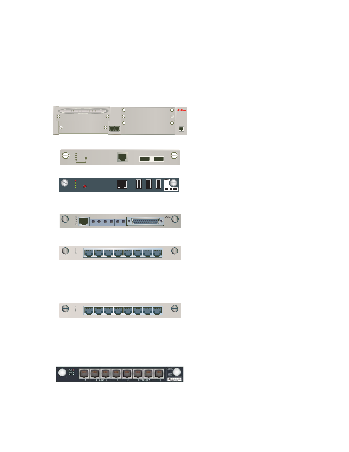
Optional USB modem.
Material ID: 700235526
Optional CD-ROM or DVD/CD-RW drive:
● Teac USB CD-ROM Drive. Material
ID: 700289580.
● Addonics USB DVD/CD-RW Drive.
Material ID: 700406267
(Available with S8300C only)
● DVD/CD-RW drive for S8300/S8400.
Material ID: 700406267
Optional industrial-strength Compact Flash
card and Compact Flash drive available
through your Avaya sales representative.
h1dccfla LAO 110306
Optional Uninterruptable Power Supply
(UPS) for AC-Powered Gateways Only.
Note:
Note: A stand-alone version of the
UPS is shown.
Issue 8 February 2007 9
Page 10
Conduct Equipment Inventory
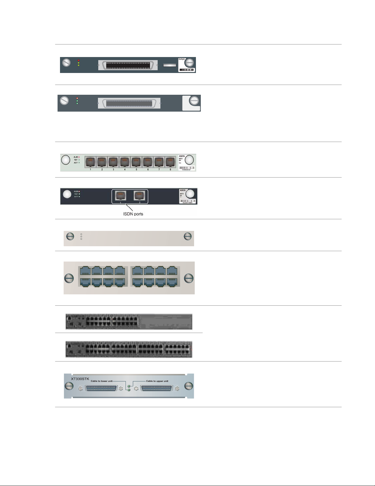
Screw Packet and Rack Mount Brackets
For each bracket:
● three flat-head machine screws
attach the bracket to the G700
● two round-head lock-washer machine
screws attach the bracket to the rack
Note:
Note: There are four sizes of
lock-washer screws in the
packet for attaching the
brackets to the rack. Use the
appropriate size screws to
match the specific hole size
of the rack.
Optional X330SC Short Cable.
Note:
Note: The X3300SC Short Cable
is sometimes shipped
attached to the X3300STK
Octaplane Stacking Module.
Optional X3300RC Redundancy Cable.
Optional X3300 LC Long Cable.
10 Quick Start for Hardware Installation: G700 Media Gateway & S8300 Media Server
Page 11

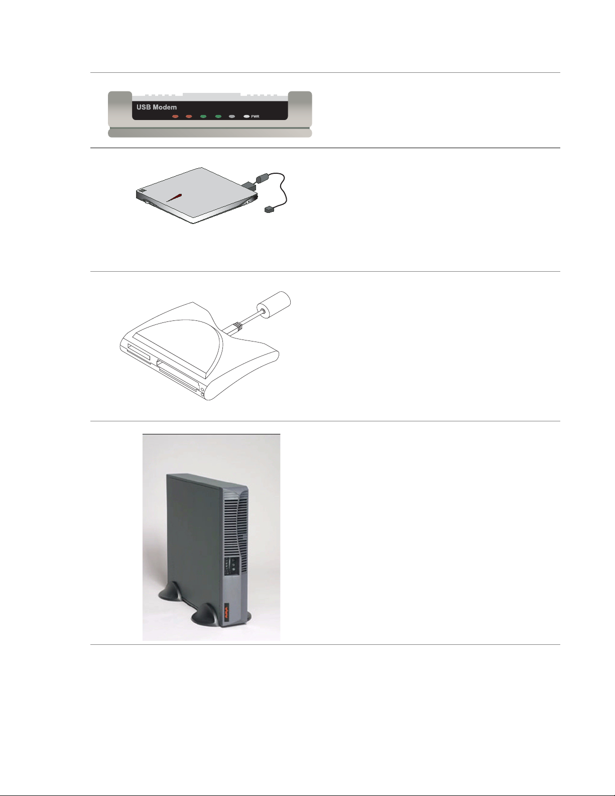
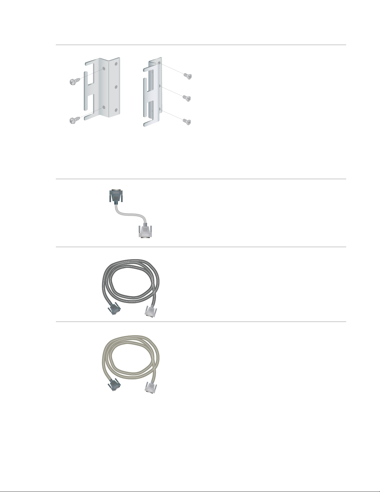
Optional USB Cable and Adapter for use
with the USB modem.
Crossover Ethernet Cable (CAT5)
Serial or "Console" Cable and Adapter
Ground wire.
Issue 8 February 2007 11
Page 12

Conduct Equipment Inventory
Optional AC Power Cord
Optional DC Power Cord.
Feet used for table mounting.
12 Quick Start for Hardware Installation: G700 Media Gateway & S8300 Media Server
Page 13

Chapter 3: Mount Media Gateway
1. Wear an anti-static ground wrist strap
and attach to an approved ground.
2. For rack mount, install the mounting
brackets on the left and right sides of
the gateway chassis using the
flathead screws from the bracket
packet.
Note:
Note: The brackets can also be
3. Lift the media gateway chassis and
mount in a rack using two lock-washer
screws for each bracket.
installed in the middle of the
chassis.
!
CAUTION:
CAUTION: The weight of the media
gateway is unevenly
distributed and may require
two persons to mount in the
rack.
Issue 8 February 2007 13
Page 14

Mount Media Gateway
ALM PWR CPU MSTR LNK COL Tx Rx FDX FC Hspd LAG
V1
51 52 53 54 55 56 57 58
59 60 61 62 63 64 65 66
4. For desktop mount. Install feet using
EXT1
EXT1 EXT2
V3
V4
V2
EXT2
plastic push rivets.
5. Connect the ground wire to the ground
conductor on the back of the media
gateway.
6. Attach the other end of the ground
wire to an approved ground.
14 Quick Start for Hardware Installation: G700 Media Gateway & S8300 Media Server
Page 15

Chapter 4: Install Octaplane Stacking Module
Note:
Note: Complete these steps only if you are connecting more than one G700 Media
Gateway in a stack configuration.
1. Remove the blank faceplate from
the Octaplane slot on the back of
the media gateway.
2. Align the X330STK Octaplane
Stacking Module with the interior
guides and insert until firmly
seated
!
WARNING:
WARNING: To prevent damage to
equipment, handle the
module by the
faceplate or edge.
3. Tighten the captive screws.
Issue 8 February 2007 15
Page 16

Install Octaplane Stacking Module
16 Quick Start for Hardware Installation: G700 Media Gateway & S8300 Media Server
Page 17

Chapter 5: Connect Media Gateways
Note:
Note: Complete these steps only if you are connecting more than one G700 Media
Gateway in a stack configuration.
1. Using the gray X330SC short cables,
connect the media gateways from the
bottom up:
● Connect the light gray connector to the
port labeled “Cable to upper unit.”
● Connect the dark gray connector to the
port labeled “Cable to lower unit.”
● Repeat both steps until all units in the
stack are connected (maximum of 10
units).
Single-stack redundancy
2. For single-stack redundancy, connect the
bottom unit and the top unit using the
black X330RC redundancy cable:
● Connect the light gray connector to the
port labeled “Cable to upper unit: on
the top unit of the stack.
● Connect the dark gray connector to the
port labeled “Cable to lower unit” on
the bottom unit of the stack.
Issue 8 February 2007 17
Page 18

Connect Media Gateways
3. For multiple stack redundancy, connect
the stacks using the black X330RC
redundancy cable and the gray X330LC
long cable:
● Connect the light gray connector of the
black X330RC redundancy cable to the
port labeled “Cable to upper unit” on
the top unit of the stack 2.
● Connect the dark gray connector of the
black X330RC redundancy cable to the
port labeled “Cable to lower unit” on
the top unit of the stack1.
● Connect the light gray connector of the
gray X3300LC long cable to the port
labeled “Cable to upper unit” on the top
unit of the stack 1.
● Connect the dark gray connector of the
gray X330LC long cable to the port
labeled “Cable to lower unit” on the
bottom unit of the stack 2.
Multiple-stack redundancy
18 Quick Start for Hardware Installation: G700 Media Gateway & S8300 Media Server
Page 19

Chapter 6: Install S8300 Media Server
Note:
Note: Complete these steps if you are installing an S8300 Media Server (configured as
the primary controller or as a Local Survivable Processor).
1. From the front of the G700 Media
Gateway, remove the blank faceplate
from slot V1.
2. For an S8300B, remove the LED
module (located above slot V1) and
place in an anti-static bag.
For an S8300C, you do not need to
remove the LED module.
3. Align the S8300 Media Server with the
lower interior guides.
For an S8300B, insert about 2" into slot
V1.
For an S8300C, insert all the way into
slot V1 until the faceplate is flush with
the LED module.
Issue 8 February 2007 19
Page 20

Install S8300 Media Server
4. For an S8300B, align the LED module
with the upper interior guides and
insert until the faceplate is flush with
the S8300B Media Server.
5. For an S8300B, continue inserting both
modules together until firmly seated.
!
WARNING:
WARNING: Failure to seat both modules
together could result in
equipment damage.
ALM PWR CPU MSTR LNK COL Tx Rx FDX FC Hspd LAG
ALM
V1
TST
ACT
OK TO
REMOVE
SHUT DOWN
51 52 53 54 55 56 57 58
59 60 61 62 63 64 65 66
SERVICES USB1 USB2
V2
6. Tighten the captive screws on the
EXT2
EXT1
EXT1 EXT2
V3
V4
S8300.
20 Quick Start for Hardware Installation: G700 Media Gateway & S8300 Media Server
Page 21

Chapter 7: Install Media and Expansion Modules
Note:
Note: In each gateway, a single expansion module can be installed in the lower left slot
only. If the S8300 is installed (in slot V1), up to 3 media modules can be installed
in slots V2–V4. If no S8300 is installed, a fourth media module can be installed in
Slot V1.
1. To install a media module, first remove
the upper right blank faceplate.
Note:
Note: All slots must have either a
module installed or be
covered by a blank face plate.
Do not leave any slots
uncovered.
2. Align the media module with the interior
guides and insert into slot until firmly
seated.
3. Tighten the captive screws.
4. Repeat steps 1 through 3 for each media
module to be installed.
5. To install the expansion module, first
remove the lower left blank faceplate.
6. Align the expansion module with the
interior guides and insert into slot until
firmly seated.
7. Tighten the captive screws.
Issue 8 February 2007 21
Page 22

Install Media and Expansion Modules
22 Quick Start for Hardware Installation: G700 Media Gateway & S8300 Media Server
Page 23

Chapter 8: Install USB Modem and CD-ROM Drive
USB Modem
1. Connect the USB cable to one of the
USB ports on the faceplate of the S8300.
2. Following the instructions packaged with
the modem, connect the other end of the
USB cable to the modem.
3. Connect the analog telephone lin e to the
RJ-11 jack on the modem.
USB CD-ROM/DVD Drive
The USB CD-ROM or DVD/CD-RW drive is
used primarily as a software source location
when remastering an S8300 hard drive.
1. Connect the USB cable into one of the
USB ports on the faceplate of the S8300.
2. Connect the other end of the USB cable
to the CD-ROM or DVD/CD-RW drive.
3. If you are using an Addonics DVD/
CD-RW drive, connect the power cord to
the drive and an electrical outlet.
Note:
Note: The TEAC drive and S8300/
S8400 drive get their power
from the server over the USB
connection.
A
ddonics
4. If you are using an Addonics DVD drive,
set the power source switch on the side
to EXT, not USB. See item 1 in the figure
to the left.
1
EXT
5. If you are using an S8300/S8400 DVD/
h1dcadvd LAO 103006
CD-RW drive, set the on/off switch to
On.
Be sure to set the S8300/S8400 drive to
Off when not in use.
Issue 8 February 2007 23
Page 24

Install USB Modem and CD-ROM Drive
24 Quick Start for Hardware Installation: G700 Media Gateway & S8300 Media Server
Page 25

Chapter 9: Install UPS and Apply Power
UPS (AC only)
1. The UPS is an option for AC-powered
gateways only. From the back of the
G700 Media Gateway, connect the
Uninterruptable Power Supply (UPS)
using the manufacturer’s instructions.
Note:
Note: A stand-alone version of the
UPS is shown.
AC power
1. Apply power to each media gateway
by connecting the AC power cord.
Note:
Note: There is no on/off switch.
The units will power up
when connected.
Issue 8 February 2007 25
Page 26

Install UPS and Apply Power
DC power
1. Apply power to each media gateway
by connecting the DC power cord.
Note:
Note: There is no on/off switch.
The units will power up
when connected.
26 Quick Start for Hardware Installation: G700 Media Gateway & S8300 Media Server
Page 27

Chapter 10: Connect the Laptop — G700 without an
S8300
This section assumes the G700 does not contain an S8300 Media Server. Use the Gateway
Installation Wizard from the laptop to enter the initial gateway configuration parameters.
1. Connect the RJ45 end of a serial
cable to the Console port on the
lower right of the front of the
G700.
2. Connect the other end of the
cable to the Serial port on the
laptop.
3. Power on the laptop.
4. Start a Hyperterm (or similar
application) session.
5. Start the Gateway Installation
Wizard (GIW).
Issue 8 February 2007 27
Page 28

Connect the Laptop — G700 without an S8300
6. Follow the GIW instructions to
Enter the configuration
parameters.
ALM PWR CPU MSTR LNK COL Tx Rx FDX FC Hspd LAG
V1
51 52 53 54 55 56 57 58
59 60 61 62 63 64 65 66
V2
To connect to the customer’s
EXT2
EXT1
EXT1 EXT2
V3
V4
LAN
1. Connect a straight Ethernet
cable to one of the Ethernet
ports (labeled Ext 1 and Ext 2)
on the front of the G700.
2. Connect the other end of the
cable to a LAN connector.
28 Quick Start for Hardware Installation: G700 Media Gateway & S8300 Media Server
Page 29

Chapter 11: Connect the Laptop — G700 with S8300
This section assumes the G700 has an S8300 Media Server installed.
1. Connect a crossover Ethernet cable to
the Services port on the faceplate of the
S8300 Media Server.
2. Connect the other end of the cable to
the Ethernet port on the laptop.
3. Power on the laptop.
4. Start an SSH session with PuTTY or
another SSH tool.
5. Use SSH to connect to 192.11.13.6.
6. Specify port 22, if requested.
7. When the first RP installer page
appears, select options as appropriate
and continue to complete the software
installation.
Issue 8 February 2007 29
Page 30

Connect the Laptop — G700 with S8300
8. Verify the Services network settings:
a. IP Address: 192.11.13.5
b. Subnet Mask: 255.255.255.252
c. Domain Name Service (DNS):
disabled.
9. Open MS Internet Explorer and disable
the Proxy Server.
10. In the browser address field, initiate
access to the S8300 by typing in lower
case:
http://192.11.13.6
11. Click Continue to access the Logon
page.
12. Click OK or Yes, as appropriate, for any
security pages that may appear prior to
the Logon page.
13. Log in to the S8300 Media Server with
the craft login and password for initial
installation.
30 Quick Start for Hardware Installation: G700 Media Gateway & S8300 Media Server
Page 31

14. Select Administrator Accounts from the
menu, and add a super-user (SUSER)
login. Assign the login to the suser
login group of and the prof18 additional
group.
Note:
Note: An SUSER group must be
created before you can install
the authentication file. The
authentication file is installed
automatically by the Avaya
Installation Wizard.
15. Use the Avaya Inst allation Wizard. Click
on Launch Avaya Installation Wizard
and continue.
Note:
Note: If you are not using the
Avaya Installation Wizard,
refer to Installation and
Upgrades for Avaya G700
Media Gateway and Avaya
S8300 Media Server,
555-234-100, for additional
instructions.
ALM PWR CPU MSTR LNK COL Tx Rx FDX FC Hspd LAG
V1
51 52 53 54 55 56 57 58
59 60 61 62 63 64 65 66
V2
To connect to the customer’s LAN
EXT2
EXT1
EXT1 EXT2
V3
V4
1. Connect a straight Ethernet cable to
one of the Ethernet ports (labeled Ext 1
and Ext 2) on the front of the G700.
2. Connect the other end of the cable to a
LAN connector.
Issue 8 February 2007 31
Page 32

Connect the Laptop — G700 with S8300
To connect USB Modem
To configure the G700 and S8300 remotely ,
connect the USB modem.
1. Connect the USB cable to either of the
two USB port on the faceplate of the
S8300.
2. Following the instructions packaged
with the modem, connect the other end
of the USB cable to the modem.
3. Connect the analog telephone line to
the RJ-11 jack on the modem.
4. Go to the Maintenance Web Interface
and select Modem in the Security
Category.
5. Select the box labeled "Enable modem
for unlimited incoming calls" an click
Submit.
32 Quick Start for Hardware Installation: G700 Media Gateway & S8300 Media Server
 Loading...