

Avaya RS9 Site Operation, Installation And Operator's Manual

Site Preparation,
Installation and Operator’s Manual
for
Avaya RS9 Uninterruptible Power Systems
Material Code 700255599
Issue 1
Copyright 2002 Avaya Inc.
All Rights Reserved


Site Preparation,
Installation and Operator’s Manual
for
Avaya RS9 Uninterruptible Power Systems
Material Code 700255599
Issue 1
Copyright 2002 Avaya Inc.
All Rights Reserved
Requesting a Declaration of Conformity
Units that are labeled with a CE mark comply with the following harmonized standards and EU directives:
:
Harmonized Standards: EN 50091-1-1 and EN 50091-2; IEC 950 Second Edition, Amendments A1, A2, A3, and A4
:
EU Directives: 73/23/EEC, Council Directive on equipment designed for use within certain voltage limits
The EC Declaration of Conformity is available upon request for products with a CE mark. For copies of the EC
Declaration of Conformity, contact:
Powerware Corporation
Koskelontie 13
FIN-02920 Espoo
Finland
Phone: +358-9-452 661
Fax: +358-9-452 665 68
93/68/EEC, Amending Directive 73/23/EEC
89/336/EEC, Council Directive relating to electromagnetic compatibility
92/31/EEC, Amending Directive 89/336/EEC relating to EMC
Class A EMC Statements
FCC Part 15
NOTE This equipment has been tested and found to comply with the limits for a Class A digital device, pursuant to
part 15 of the FCC Rules. These limits are designed to provide reasonable protection against harmful interference when
the equipment is operated in a commercial environment. This equipment generates, uses, and can radiate radio frequency
energy and, if not installed and used in accordance with the instruction manual, may cause harmful interference to radio
communications. Operation of this equipment in a residential area is likely to cause harmful interference in which case
the user will be required to correct the interference at his own expense.
ICES-003
This Class A Interference Causing Equipment meets all requirements of the Canadian Interference Causing Equipment
Regulations ICES-003.
Cet appareil numérique de la classe A respecte toutes les exigences du Reglement sur le matériel brouilleur du Canada.
EN 50091-2
Some configurations are classified under EN 50091-2 as “Class-A UPS for Unrestricted Sales Distribution.” For these
configurations, the following applies:
WARNING This is a Class A-UPS Product. In a domestic environment, this product may cause radio interference, in
which case, the user may be required to take additional measures.
VCCI Notice
Avaya and the Avaya logo are trademarks of Avaya Inc. and may be registered in certain jurisdictions.
.
Copyright 2002 Avaya Inc. All rights reserved. No part of this document may be reproduced in any way without the
express written approval of Avaya Inc.

TABLE OF CONTENTS
1 Introduction 1....................................................
Power Modules 1..............................................................
Battery Configurations 1.........................................................
Battery Charger Modules 2.......................................................
Safety Warnings 2.............................................................
Physical Features 3.............................................................
2 Installation Setup 7...............................................
Equipment Clearances 7.........................................................
Location Requirements 7.........................................................
UPS Setup 8.................................................................
Moving the Cabinets 10..........................................................
3 Electrical Installation 11............................................
Input Current Ratings 12..........................................................
UPS Installation 13..............................................................
System Wiring Diagram 18........................................................
4 Battery Cabinet Installation 19.......................................
5 UPS Startup 21....................................................
Power and Battery Module Installation 22..............................................
UPS Startup 23................................................................
Initial Startup Parameters 25.......................................................
6 Operation 29......................................................
Turning the UPS On 30...........................................................
Removing Input Power 31.........................................................
Front Panel Display 31...........................................................
Using the Front Panel Display 32....................................................
Parameters 34.................................................................
Changing Parameter Settings 34....................................................
Reading the Avaya RS9 System Logs 35...............................................
Inverter Log 35..............................................................
Alarm Log 36...............................................................
Menu Map 37.................................................................
AvayaZRS9 UPS Site Preparation, Installation and Operator’s Manual : 700255599 Issue 1
i

Table of Contents
7 Communication 39.................................................
LanSafe III Power Management Software 39............................................
Optional Internal Web/SNMP Card 40................................................
Optional Relay Card 40...........................................................
Communication Slots 40..........................................................
Dedicated Input Signals 41........................................................
DB-9 Communication Port 42.......................................................
8 Maintenance 43...................................................
Storage Temperature 44..........................................................
Battery Replacement 44..........................................................
Power Module or Battery Charger Module Replacement 45.................................
9 Specifications 47..................................................
10 Troubleshooting 51................................................
Alarms 52....................................................................
Obtaining Service 57............................................................
ii
AvayaZRS9 UPS Site Preparation, Installation and Operator’s Manual : 700255599 Issue 1

CHAPTER 1
INTRODUCTION
The AvayaZ RS9 uninterruptible power system (UPS) is a modular UPS
that contains battery modules and power control modules (referred to as
power modules). These modules plug into a rack cabinet structure
containing additional control, communication, and display functions
that enable integrated control of all power modules. The UPS is housed
in a single cabinet, with extra battery capacity housed in auxiliary
battery cabinets.
Power Modules
The pluggable power modules can be removed and replaced
(hot-swapped) without powering the UPS down if the UPS has sufficient
redundant capacity. Battery modules may also be hot-swapped for
maintenance. Power control circuitry in the cabinet senses problems in
power modules, and automatically transfers control and load to the
remaining power modules.
All power modules share the load requirements equally. For example,
three power modules are capable of supplying a total of 9 kVA. If a load
requires only 4.5 kVA, each power module supplies 1.5 kVA to the
output. If one power module is removed or for some reason fails, each of
the two remaining power modules would supply half of the load, or
2.25 kVA. In other words, redundancy exists when the load can be
supplied by less than all of the installed power modules.
Battery Configurations
The Avaya RS9 UPS has two different options for additional battery
configurations:
External Battery Module Cabinet (EBMC) - this cabinet is recommended
:
for applications that require less than two hours of run time. One
EBMC can be connected to the UPS.
120 Vdc Extended Battery Cabinet (EBC120) - this cabinet is recommended
:
for applications that require more than two hours of run time. Up to
14 EBC120s can be connected to the UPS.
AvayaZRS9 UPS Site Preparation, Installation and Operator’s Manual : 700255599 Issue 1
1
Introduction
Battery Charger Modules
NOTE One battery charger module is required for every five EBC120s. A 12-slot
cabinet with 37 battery strings also requires one battery charger module.
The optional battery charger module is designed to provide additional
current for faster recharging of UPS battery modules in systems with
many batteries. It is capable of providing up to 20 amperes of current for
optimum charging, based upon the condition and number of batteries in
the system.
The battery charger module is similar in appearance to a power module.
The primary difference is the light-purple colored front label. It can be
plugged into any UPS cabinet slot above the battery modules.
The battery charger module operates in automatic modes within the UPS
cabinet under control of the UPS power modules. It communicates
through a controller area network (CAN) bus with the power modules.
The power modules monitor and control the battery charger. Alarm
conditions detected by the battery charger module are logged and
announced by the UPS system (refer to the UPS user’s guide). Normal
output voltage is 133 Vdc.
Safety Warnings
2
Read the following precautions before you install the UPS.
IMPORTANT SAFETY INSTRUCTIONS
SAVE THESE INSTRUCTIONS. This manual contains important instructions that you
should follow during installation and maintenance of the UPS and batteries. Please
read all instructions before operating the equipment and save this manual for future
reference.
CAUTION
: A maximum of seven power and/or battery charger modules can be installed in the
system.
: Battery modules used in the Avaya RS9 system weigh 30 lb (14 kg). Use care in
lifting and moving battery modules.
: All input and output wiring must be copper and adequate to carrying currents as
listed in Table 8 on page 48.
AvayaZRS9 UPS Site Preparation, Installation and Operator’s Manual : 700255599 Issue 1
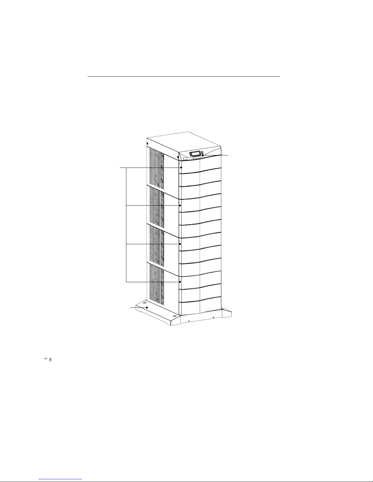
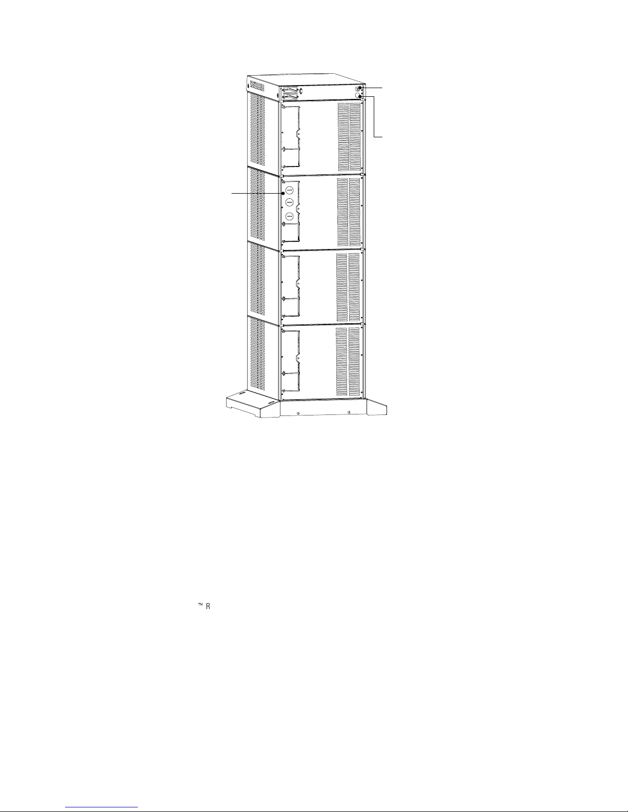
Physical Features
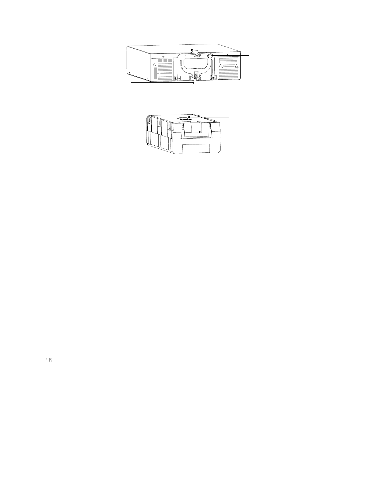
Figure 1 shows the 12-slot UPS cabinet and identifies basic Avaya RS9
system features. A 12-slot External Battery Module Cabinet is also
available.
Introduction
: Torque all bolts holding input and output power conductors to values specified in
Table 2 on page 12.
: The user is required to provide power input and output disconnect devices for the
UPS. These must be within sight of the UPS and easily accessible.
Front Panel
Display
Front Cover
Panels
Cabinet Base
AvayaZRS9 UPS Site Preparation, Installation and Operator’s Manual : 700255599 Issue 1
Figure 1. 12-Slot Cabinet (Front View)
3
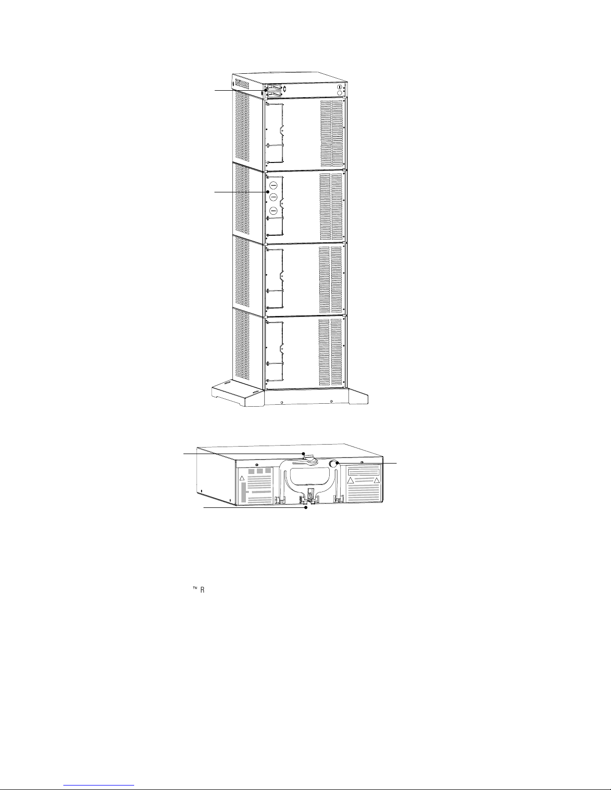
Introduction
Communication
Slots
Entrance Panel
Figure 2. 12-Slot Cabinet (Rear View)
Handle/Latch
Release
Insertion/Extraction
Cams
Handle
Thumbscrew
Figure 3. Power Module (700248974)
4
AvayaZRS9 UPS Site Preparation, Installation and Operator’s Manual : 700255599 Issue 1
Introduction
Handle/Latch
Release
Insertion/Extraction
Cams
Handle
Thumbscrew
Figure 4. Battery Charger Module (700249030)
Secondary Stop
Release
Latch Release
Figure 5. Battery Module (700248982)
AvayaZRS9 UPS Site Preparation, Installation and Operator’s Manual : 700255599 Issue 1
5

Introduction
6
AvayaZRS9 UPS Site Preparation, Installation and Operator’s Manual : 700255599 Issue 1

CHAPTER 2
INSTALLATION SETUP
This chapter explains how to setup and install the Avaya RS9 cabinets:
Clearances and location requirements
:
Setup, including stabilizer bracket installation
:
Moving the cabinets
:
Equipment Clearances
All cabinets require the following clearances to allow for servicing and
adequate ventilation:
Fromthesidepanels: 62(15.2 cm)
:
Top and back: 122(30.5 cm)
:
Front: 362(91.5 cm)
:
If flexible conduit connects the UPS to the service input and load
distribution panels, you may be able to gain access for servicing by
moving the UPS. If this is the case, you must still leave 122(30.5 cm)
clearance at the back and 62(15.2 cm) at the sides of the UPS for
ventilation.
NOTE Do not block the ventilation holeson each side and the back of the unit.
Location Requirements
Install the Avaya RS9 UPS as close as possible to the equipment or
the load distribution panel it will protect. If this distance is more than
25 ft (7.6m), transient noise can reappear in the electrical distribution
system.
If a separate battery cabinet is installed (either an External Battery
Module Cabinet or 120 Vdc Extended Battery Cabinet), the battery
cabinets must be adjacent to the Avaya RS9 UPS.
AvayaZRS9 UPS Site Preparation, Installation and Operator’s Manual : 700255599 Issue 1
7

Installation Setup
UPS Setup
The Avaya RS9 UPS is shipped in a carton on a shipping pallet. Power
and battery modules are shipped in separate boxes on another pallet.
NOTE Do not attempt to lift the cabinet by the module shelves or other convenient
edges or panels.
NOTE The Avaya RS9 UPS requires stabilizer brackets on non-seismic models. If you
ordered a seismic model, follow the instructions included with the unit. Otherwise, the
stabilizer brackets that are shipped with the UPS MUST be installed.
NOTE If you ordered a non-seismic External Battery Module Cabinet, the stabilizer
brackets that are shipped with the battery cabinet MUST be installed.
The Avaya RS9 UPS cabinet is shipped with two stabilizer brackets.
Under all module-loading conditions, they act as a protective stop to
prevent the cabinet from falling forward if it is unintentionally pushed
away from the wall.
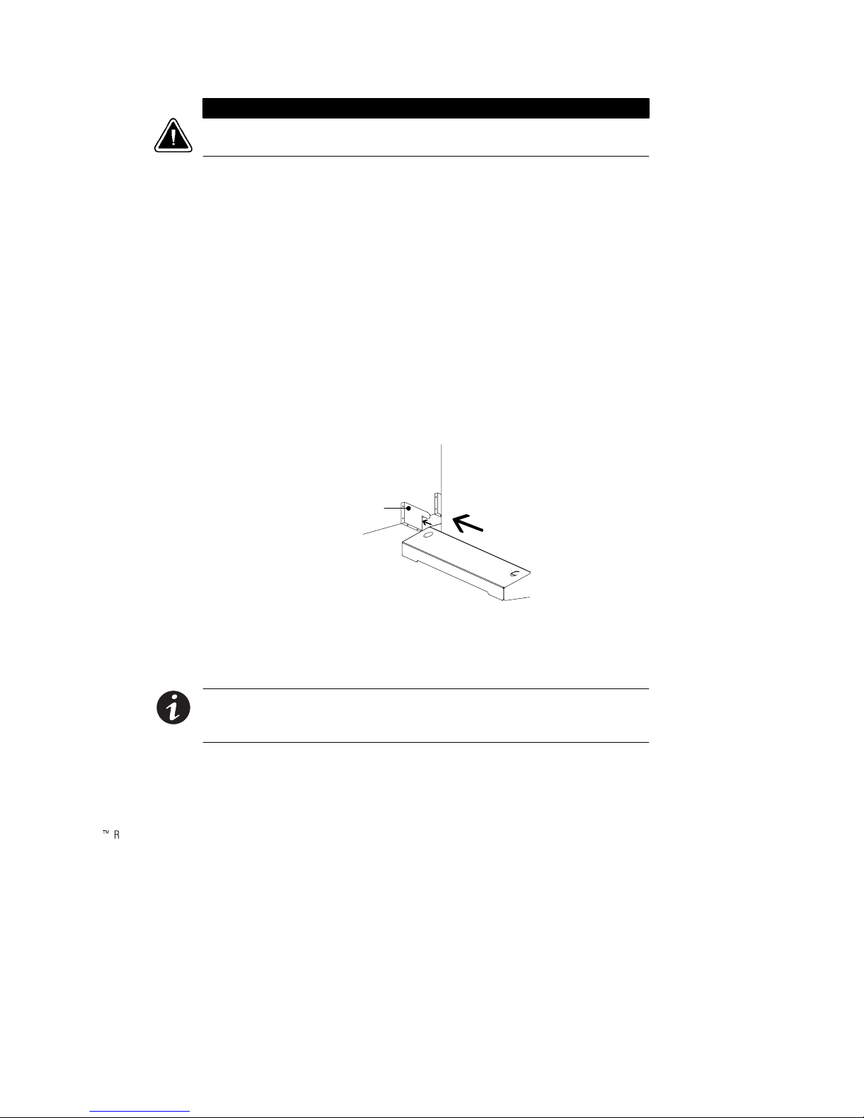
Each stabilizer bracket has holes that enable it to be attached by screws
to either the wall or the floor (or both) behind the intended cabinet
installation (see Figure 6). The stabilizer brackets are not attached to the
cabinet base itself.
Use the following procedure to set up the Avaya RS9 cabinet and install
the stabilizer brackets:
1. Open the top of the carton by cutting the straps that hold the
cover to the carton. Lift the cover off.
2. Remove the pallet ramp packed on top of the cabinet. Locate
the ramp-mounting hardware (supplied in the accessory kit)
and attach the ramp to the pallet as shown in the unpacking
instruction sheet.
3. Remove any packing material inside the carton. Also remove
the cartons inside the cabinet module slots containing front
cover panels, electrical or mechanical hardware, and printed
material.
8
AvayaZRS9 UPS Site Preparation, Installation and Operator’s Manual : 700255599 Issue 1
Installation Setup
CAUTION
Do NOT lower the casters or attempt to move the cabinet with the power or battery
modules installed.
4. Select the location for the stabilizer brackets, approximately
12–162(30–41 cm) apart, at the floor/wall intersection behind
the intended cabinet location.
5. Using the proper type of customer-supplied screws for the
intended mounting surface, attach each stabilizer bracket as
shown in Figure 6. All screws must be driven into structural
material such as wall studs.
6. Lower the four cabinet casters (one at each corner of the
cabinet base) by using a 1/22hex-style socket wrench to turn
each bolt clockwise.
7. With all casters fully extended, carefully roll the cabinet down
the ramp and to its intended operating location. Position the
rear section of the cabinet base under the open ends of the
stabilizer brackets as far as the cabinet will go.
Stabilizer Bracket
Figure 6. Stabilizer Bracket Installation
8. Turn all four caster bolts counter-clockwise until the cabinet
rests on the floor. Place a plastic cap into each bolt access hole.
NOTE If the floor is uneven and the cabinet is tilted or unstable, you may need to
place a thin steel plate under a corner.
cabinet.
AvayaZRS9 UPS Site Preparation, Installation and Operator’s Manual : 700255599 Issue 1
Do not use the caster bolts to level the
9

Installation Setup
9. If you ordered the EBMC, repeat these steps to setup the
10. If you ordered an optional battery cabinet (either EBMC or
Moving the Cabinets
The Avaya RS9 UPS and EBMC are very heavy with power and battery
modules installed. Before moving the cabinets, remove the power and
battery modules. Move the modules separately from the cabinets.
Do NOT attempt to raise the cabinet with the power or battery modules installed.
Use the following procedure to raise the cabinet before rolling it on its
casters.
1. Ensure that the cabinet contains no power or battery modules.
2. Locate the four plastic caps covering the caster bolts at the
3. Pry the caps out of the bolt access holes.
4. Usea1/22hex-style socket wrench to turn each of the four
5. Slide the cabinet base out from under the stabilizer brackets in
6. Remove the stabilizer brackets from the floor/wall. Follow
7. After properly positioning and leveling the cabinet, insert
cabinet.
EBC120), continue to “Battery Cabinet Installation” on
page 19.
If you do not have a battery cabinet, continue to “Electrical
Installation” on page 11 to hardwire the UPS.
CAUTION
corners of the cabinet base.
bolts clockwise. Doing so lowers the casters to allow the cabinet
to roll on the casters.
the rear section of the cabinet base.
Steps 4 through 8 on page 9 to reinstall the stabilizer brackets
and cabinet in the new location.
power and battery modules into the cabinet as described in
“UPS Startup” on page 21.
10
AvayaZRS9 UPS Site Preparation, Installation and Operator’s Manual : 700255599 Issue 1

CHAPTER 3
ELECTRICAL INSTALLATION
Only qualified service personnel (such as a licensed electrician) MUST perform the
electrical installation. Risk of electrical shock.
The UPS input must be hardwired through conduit to a main power
source circuit breaker, and the UPS output must be hardwired to a
circuit breaker in a distribution panel (as shown in Figure 7).
WARNING
Building
Service
Panel
User-supplied
(If Required)
Figure 7. Avaya RS9 Typical Installation
External Batteries
Load
Distribution
Panel
(Optional)
AvayaZRS9 UPS Site Preparation, Installation and Operator’s Manual : 700255599 Issue 1
11
Electrical Installation
Input Current Ratings
Table 1 contains the required circuit breaker ratings for hardwired
installations.
Table 1. Required Input Circuit Breaker Sizes (200–240 Vac, 60 Hz)
UPS Capacity Input Circuit
Breaker Rating
9kVA 60A 75A 100A N/A
12 kVA 80A 100A 125A 125A
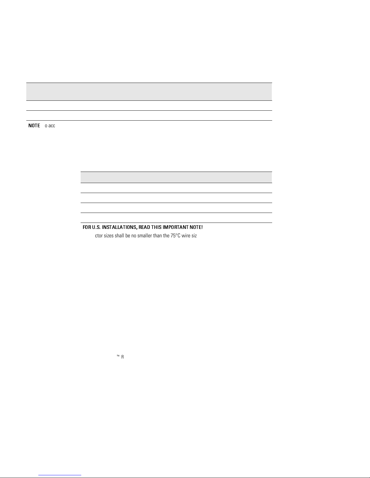
NOTE
To accommodate the feature of easy system expandability, it is recommended that initial installation of the Avaya
RS9 UPS contain wiring to support a 12 kVA unit.
See Table 2 for recommended conductor size to wire the input circuit
breaker.
Table 2. Recommended Wire Sizes
Input Circuit Breaker Size 75°C Copper Wire Size Conductor Screw Torque
60A 4AWG(21.2mm2) 35 in lb (4.0 Nm)
75A, 80A 3AWG(26.7mm2) 45 in lb (5.1 Nm)
100A 2AWG(42.1mm2) 55 in lb (6.2 Nm)
125A 1/0 AWG (53.5 mm2) 65 in lb (7.3 Nm)
FOR U.S. INSTALLATIONS, READ THIS IMPORTANT NOTE!
Conductor sizes shall be no smaller than the 75°C wire size based on the ampacities given in
Table 310–16 of the National Electrical Code, ANSI/NFPA 70-1999, and article 220. All circuit
conductors, including neutral conductor, must be the same size (ampacity) wire. Code may
require a larger AWG size than shown in this table because of temperature, number of
conductors in the conduit, or long service runs. Follow local code requirements.
UPS with 1 Battery
Charger Module
UPS with 2 Battery
Charger Modules
UPS with 3 Battery
Charger Modules
12
AvayaZRS9 UPS Site Preparation, Installation and Operator’s Manual : 700255599 Issue 1
UPS Installation
Electrical Installation
WARNING
Only qualified service personnel (such as a licensed electrician) MUST perform the
electrical installation. Risk of electrical shock.
CAUTION
To prevent electrical shock or damage to the equipment, verify that the Avaya RS9 UPS
is OFF before you remove the entrance panel. The circuit breaker or disconnect switch
must also be off at the AC input service panel.
1. Unscrew and remove the top two rear panels of the UPS (see
Figure 8).
The entrance panel, located in the second section, contains
knockout openings for entrance and exit conduits. See
Figure 8.
Wiring for optional emergency power-off (EPO) passes through
the opening at the top back of the cabinet. Wiring for an
optional generator input signal must pass through a separate
opening. Installing this wiring is described in Steps 8 and 9 on
page 17.
AvayaZRS9 UPS Site Preparation, Installation and Operator’s Manual : 700255599 Issue 1
13
Electrical Installation
Wiring Access Hole
for Optional EPO
Wiring Access Hole
for an Optional
Generator Input
Signal
Entrance Panel
14
Figure 8. UPS Power Entrance Panel and Wiring Knockouts
2. Remove the knockouts in the entrance panel for AC input and
AC output wiring.
3. Install the conduit adapters. AC input and AC output
conductors must be run through separate conduits. UPS output
circuits must be installed in dedicated conduit systems and not
shared with other electrical circuits.
4. Torque the screws holding all input and output power
conductors to the values specified in Table 2 on page 12.
AvayaZRS9 UPS Site Preparation, Installation and Operator’s Manual : 700255599 Issue 1
 Loading...