

Page 1

Table of Contents
1 Quick Start
Overview 1-1
Kit Contents 1-3
Network Options 1-4
2 Connect & Power Up
Connect Cables 2-2
Power-up the Unit 2-6
Network Name 2-9
3 Customize the Residential Gateway-I settings
Introduction 3-1
Internet Service Provider Information 3-2
View/Modify Residential Gateway-I Settings 3-4
Finding Information 3-6
Access Point-I - Getting Started Guide
i
Page 2

4 Using your Residential Gateway-I
General Guidelines 4-1
Residential Gateway-I Buttons 4-4
Special modes Residential Gateway-I 4-7
A Specifications
Technical Specifications A-1
Power Specifications A-2
Interfaces (built-in) A-3
Physical Specifications A-4
Radio Specifications A-5
Regulatory Information A-6
ii
Access Point-I - Getting Started Guide
Page 3

Quick Start
Overview
Follow t he quick steps described below to install the Residential Gateway-I
and power up your wireless network:
1. Connect Cables (page 2-2).
2. Power- up the Unit (page 2-6).
3. Install the Software:
a. Insert the CD-ROM that came with your Residential Gateway-Ik it
into your computer.
Your operating s ystem will run the CD automatically
b. Click the install buttons for the following software:
■ Client Manager, and
■ RG Setup Utility.
c. Follow the instructions on your screen.
NOTE:
If the CD-ROM does not start automatically:
1. Click the Windows
2. Select
Run
Start button
1
Residential Gateway-I - Getting Started Guide
1-1
Page 4

Quick Start - Ov erview
3. Browse to the CD-ROM
4. Double-click the file “setup.exe”.
4. Install the Avaya wireless network adapter on your computer.
■ Set the configuration profile of the wireless network adapter to
connect to a Residential Gatewa y-I.
■ Set Network Name (page 2-9) and Encryption key.
For more information, read the user documentation that came with your
wirelessnetwork adapter.
5. (Optional) Customize the Residential Gateway-I Settings.
1-2
Residential Gateway-I - Getting Started Guide
Page 5
Quick Start - Kit Contents
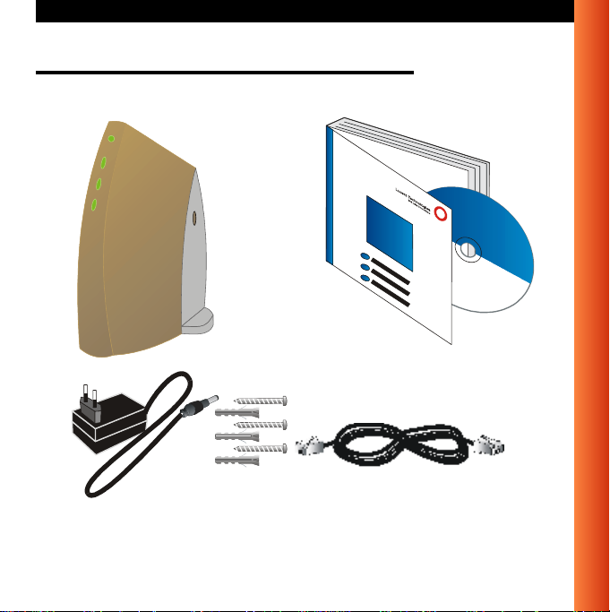
Kit Contents
Your Residential Gateway-I kit includes the following items:
Residential Gateway-I - Getting Started Guide
1-3
Page 6

Quick Start - N etwork Options
Network Options
The R esidential Gateway-I is a Base Station that bridges communication
between (wireless) computers and the Internet.
You can use the Residential Gateway-I to provide:
■ A Stand-Alone Wireless Network (page 1-5).
■ Wireless Internet Access via Telephone Line (page 1-6) using the built-in
56k/V90 modem.
■ Wireless Internet Access via External Devices (page 1-7) using an
external cable/DSL/ISDN modem.
To build your wireless network, all you need is:
■ One Residential Gateway-I, and
■ One or more Avaya Wireless Network adapter cards for computers.
1-4
Residential Gateway-I - Getting Started Guide
Page 7
Quick Start - Network Options
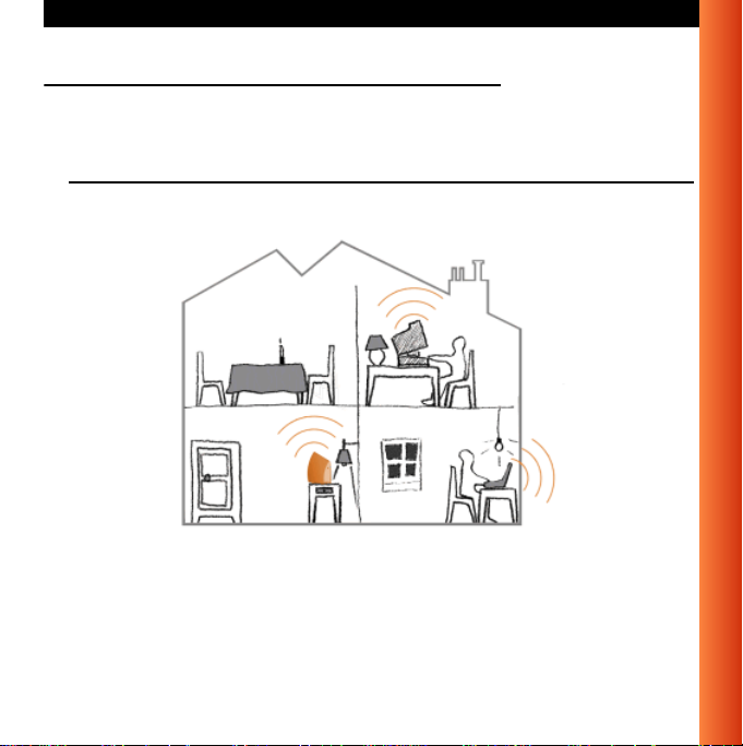
Stand-Alone Wireless Network
This is the out-of-the-box mode of operation for the Residential Gateway-I
that allows your client stations to share files and printers.
Figure 1-1 Stand-alone Wireless Network
Adding wireless computers is as easy as inserting a wireless client adapter
and configuring the computer with the same Network Name (page 2-9).
Residential Gateway-I - Getting Started Guide
1-5
Page 8
Quick Start - N etwork Options
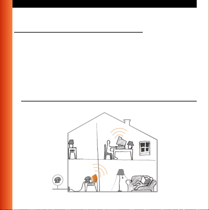
Wireless Internet Access via Telephone Line
The Residential Gateway-I includes a 56K/V90 built-in modem that allows
multiple computers to share Internet access.
To access the Internet via the Residential Gateway-I modem you will need:
■ An analog telephone line.
■ An ISP (InternetSe rvice Provider)account.
■ View/Modify Residential Gateway-I Settings (page 3-4) to enter the ISP
dial-up information to in the Residential Gateway-I.
Figure 1-2 Wireless to Internet via Telephone Line
1-6
Residential Gateway-I - Getting Started Guide
Page 9
Quick Start - Network Options
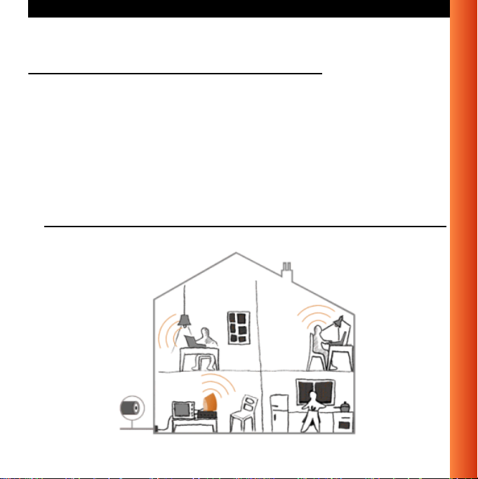
Wireless Internet Access via External Devices
To access the Internet viaan A DSL- PPPoE modem, Cableo r ISDNmodem
youwillneedto:
■ Connect the external modem to the Residential Gateway-Iusing a UTP
cable.
■ An IS P (Internet Service Provider) account.
■ View/Modify Residential Gateway-I Settings (page 3-4) to enter the
correct setting for this type of connection.
Figure 1-3 Wireless Internet Access via External Device
Residential Gateway-I - Getting Started Guide
1-7
Page 10

Quick Start - N etwork Options
Wireless Internet Access via Ethernet LAN
Some companies or educational organiz ations offer internet access to their
employees or students via an existing LAN Infrastructure.
In this mode, the Residential Gateway-I tool will:
■ Act as a transparent bridge between the wireless and wired network.
■ Disable the integrated DHCP server (i.e. the Residential Gateway-I will
no longer assign IP Addresses).
■ Try to obtain itsown IP Address from a DHCP server on the n etwork.
1-8
Residential Gateway-I - Getting Started Guide
Page 11

Quick Start - Network Options
Residential Gateway-I - Getting Started Guide
1-9
Page 12

Page 13

Connect & Power Up
Before you start, carefully read the flyer “Information to the User” that is
included in your Residential Gateway-I kit. This flyer contains installation
requirements and important information abou t using this product.
2
Residential Gateway-I - Getting Started Guide
2-1
Page 14

Connect & Power Up - Connect Cables
Connect Cables
1. Press the latches (a) and remove t he cover (b) of the Residential
Gateway-IaspicturedinFigure2-1.
Figure2-1 Removethe cover
2. Plug the power connector into the power socket on theResidential
Gateway-I unit (see Figure 2-2).
2-2
Residential Gateway-I - Getting Started Guide
Page 15

Connect & Power Up - Connect Cables
Figure 2-2 Connect Power Adapter
3. Connect the cable for internet access:
■ For Wireless Internet Access via Telephone Line (page 1-8), plug
the telephone cable to the correspondent socket (as shown in
Figure 2-3) and to the telephone outlet.
Depending onlocalstandards, you mayneed a special adapter plug
to connect the cable to the outlet.
■ For Wireless Internet Access via External Devices (page 1-9), plug
in the UTP/Ethernet cable into the ethernet socket.
Residential Gateway-I - Getting Started Guide
2-3
Page 16

Connect & Power Up - Connect Cables
Figure 2-3 Connect Telephone Cable
NOTE:
Telephone adapter plugs and Ethernet cable are not included, but
are available at your local computer dealer. See Interfaces (built-in)
(page A-3) for inform ation about cable/connector types.
4. Close the cover by attaching it to the unit, pressing the latches as
pictured in Figure 2-4.
2-4
Residential Gateway-I - Getting Started Guide
Page 17

Connect & Power Up - Connect Cables
Figure 2-4 Close the Unit
5. Place the unit on a flat surface and route the cables through the cable
entrance as shown in Figure 2-5.
Figure 2-5 Place the Residential Gateway-I on a Flat Surface
Residential Gateway-I - Getting Started Guide
2-5
Page 18

Connect & Power Up - Power-up the Unit
Power-up the Unit
1. Plug the power adapter into an ACpoweroutlet.
!
WARNING:
After applying power t o the Residential Gateway-I, do not cover the
unit or block the airflow to the unit with any other objects.
Figure2-6 Residential Gateway-ILEDs
2. Monitor the LED activity on the unit.
The LEDs (see Figure 2-6) will change color in the range Yellow, Red
and Green to indicate start-up diagnostics. When finished (after
approximately 30 seconds), the Residential Gateway-I shows LED
activity as listed in Table 2-7 on page 2-7.
2-6
Residential Gateway-I - Getting Started Guide
Page 19

Connect & Power Up - Power-up the Unit
Table 2-7 LED Activity Table - Normal Operation
Icon Name Colo r/Act ivity Description
Power Steady Green Power enabled
Wireless Flashing Green Wireless activity between
Residential Gateway-I and
wireless stations.
See also: Stand-Alone Wireless
Network (page 1-7).
Off No communication.
Ethernet Flashing Green Communication between
Residential Gateway-I and the
wired Ethernet equipment
See also: Wireless Internet
Access via External Devices
(page 1-9).
Off No communication.
Residenti
al
Gateway-I
Modem
Flashing Green Modem activity bet ween
Residential Gateway-I and your
phone line.
See also: Wireless Internet
Access via Telephone Line
(page 1-8).
Off No communication.
Residential Gateway-I - Getting Started Guide
2-7
Page 20

NOTE:
If the Residential Gateway-Idoes notswitch to normal operation
within one minute, consult the section FindingInformation
(page 3-6).
3. Now proceed with the installation of softwareas described in the Quick
Start Overview (page 1-1).
Page 21

Connect & Power Up - Network Name
Network Name
The Network Name is the unique 6-character identification code of your
wireless network. It is printed on the label, at the bottom of your Residential
Gateway-I.
Figure 2-8 Label with Network Name (example)
In earlier versions of the Residential Gateway-I devices, the Network Name
is also referred to as RG ID.
The last 5 characters of the Network Name also match the default data
encryption key.
Residential Gateway-I - Getting Started Guide
2-9
Page 22

Page 23

Customize the Residential Gateway- I set tings
Introduction
When you have installed the Wireless LAN network adapters on your
computers and set up the Residential Gateway-I, you can start to use your
Stand-Alone Wireless Network (page 1-5).
To set up your Residential Gateway-Ifor Internet access, you will need to:
1. Obtain an account with an Internet Service Provider.
2. Start the RG SetupUtility (page 3-2).
3. Enter the Internet Service Provider Information (page 3-2) into your
Residential Gateway-I configuration.
3
Residential Gateway-I - Getting Started Guide
3-1
Page 24

Customize the Residential Gateway-I settings - Internet Service
Internet Service Provider Information
When you obtain an account with the Internet Service Provider (ISP), you
will typically receive the following information:
■ Telephone numbers to dial in to your ISP
Wireless Internet Access via Telephone Line (page 1-6) option.
■ Account Name (or User Name).
■ Account Password (or User Password).
Subject to the type of internet account you may receive addit ional settings
that you might need to enter in the Residential Gateway-I conf iguration.
Startthe RG Setup Utility
1. Click th e Start button on the Windows task bar.
2. Select
3. Select
4. To connect to the Residential Gateway-I, enter the 6-character Network
5. Follow the instructions on your screen.
Programs, then select Wireless LAN.
RG Setup Utility to start the program.
Name (page 2-9) printed on the label on the device.
NOTE:
All alphabetical characters must be entered in lower-case (e.g. abc).
If you encounterdifficultyaccessing theResidential Gateway-Ito view or
modify its current settings:
3-2
Residential Gateway-I - Getting Started Guide
Page 25

Customize the Residential Gateway-I settings - Internet Service
■ View/Modify the settings of the wireless adapter in your computer to
ensure that:
— The Network Name matches the value printed on the label at
the bottom and at the back of unit.
Please note that the alphabetical characters are case-sensitive.
— The encryption key matches the value of the Residential
Gateway-I (default key matches the last five digits of the
Network Name).
■ View/Modify the Networking properties on your computer to:
— Ensure the TCP/IP protocol is installed for your wireless
network adapter.
— The TCP/IP protocol has DHCP enabled, to obtain an IP
Address from the Residential Gateway-I automatically.
Consult your Microsoft documentation and/or Help system for
information about setting the TCP/IP network protocol.
■ Consult Finding Information (page 3-6) for more information.
Residential Gateway-I - Getting Started Guide
3-3
Page 26

Customize the Residential G ateway-I settings - View/Modify Residential
View/Modify Residential Gateway-I Settings
The RG Setup Utility allows you to view or modify the followingnetwork
settings:
■ Internet Access Settings (page 3-4)
■ Wireless Connection Settings (page 3-4)
Internet Access Settings
To setup your ResidentialGateway-I for Internet access you will need
information from your Internet Service Provider (ISP), such as account
name, password,telephone number and/or IP address.
Next select how you wish to connect to your ISP:
■ Wireless Internet Access via Telephone Line (page 1-6)
■ Wireless Internet Access via External Devices (page 1-7)
Follow the instructions on your screen, or click
Wireless Connection Settings
Change these settings to increase the security of your wireless network, set
up special connectionrequirements and improve your wireless
communication.
Help for more information.
3-4
Residential Gateway-I - Getting Started Guide
Page 27

Customize the Residential Gateway-I settings - View/Modify Residential
Wireless Channel
To transmit and receive data, the Residential Gateway-I uses a frequency
channel.
If neighboring wireless networks are using the same channel, it is advisable
to have your Residential Gateway-I network using a different one.
Encryption Key
Communication within your network is only pos sible to wireless computers
using the same Encryption Key.
This is what the Residential Gateway-I uses to enable Data Security on your
wireless network.
The default value of the Encryption Key equals the 5 last (most right)
characters of the Network Name. To prevent any access to your network
without permission, it is strongly advised to change the default encryption
key value.
Residential Gateway-I - Getting Started Guide
3-5
Page 28

Customize the Residential Gateway-I settings - Finding Information
Finding Information
The G etting Started Guide provides only basic instructions.
For more detailed information:
■ Consult the CD-ROM to view other user documentation.
■ Consult the Online Help that was installed with the software. This Online
Help containsdetailed instructions, including a troubleshooting section.
For context-sensitive hel p press the
RG Setup Utility.
■ Visit our website a t: http://www.avaya.com for:
— The list of most frequently asked questions,
— The latest software and documentation for your product, and
— More resources for Technical Suppo rt.
Help button on the screens of your
3-6
Residential Gateway-I - Getting Started Guide
Page 29

Using your Residential Gateway-I
General Guidelines
When using your Residential Gateway-I please follow the guidelines listed
below:
Safety Guidelines
■ Do not cover the unit or block the airflow to the unit.
■ Keep the Residential Gateway-Iaway from excessive heat and humidity.
■ Keep the unit free from vibration and dust.
■ Always disconnect the Residential Gateway-I power adapter be fore
cleaning.
Operation Guidelines
■ To maximize the wireless coverage, place the unit as centrally as
possible (depending on the wireless computers vicinity). See also Wall
Mount the Residential Gateway-I.
4
Residential Gateway-I - Getting Started Guide
4-1
Page 30

Using your Residential Gateway-I - General Guidelines
■ The R esidential Gatew ay-I unit can be cleaned with a soft tissue. To
avoid damage, do not use aggressive liquids like alcoholor acetone. Do
not rinse the unit with fluids.
■ The ResidentialGateway-I consumes very littlepower. In order to extend
the life of your Residential Gateway-I it is betterto leave the unit powered
on.
WallMount the Residential Gateway-I
If you want to mount the Residential Gateway-I to the wall proceed as
follows:
1. Remove the cover (page 2-2).
2. Use a sharp pointed object (like a small screwdriver) to open the three
cover screw holes marked
a in Figure 4-1.
Figure 4-1 Punch Screw Holes and Mount the Residential Gateway-I to a
Wall
4-2
Residential Gateway-I - Getting Started Guide
Page 31

Using your Residential Gateway-I - General Guidelines
3. Decidewhere and how you wanttoplace the Residential Gateway-I (you
may consider to mount the unit upside dow n on high spots, to be able to
see the LEDs).
4. Place the cover against the wall, and put three marks on the wall to
indicate the screw positions.
5. Use the screws and the plugs that came with your kit to fix the cover to
the wall.
6. Close the Residential Gateway-I.
Residential Gateway-I - Getting Started Guide
4-3
Page 32

Using your Re sidential Gateway-I - Residential Gateway-I Buttons
Residential Gateway-I Buttons
The R esidential Gatew ay-I unit has two small buttons for troubleshooting
purposes.
■ Reset button (page 4-5)
■ Reload button (page 4-5)
Remove the cover (page 2-2) from the main unit to have access to these
buttons as described in “Connect Cables” on page 2-2.
Figure4-2 Reload(a) and Reset (b) Button
4-4
Residential Gateway-I - Getting Started Guide
Page 33

Using your Re sidential Gateway-I - Residential Gateway-I Buttons
Reset button
This button al lows you to recover froma situation wherefor some reason the
Residential Gateway-I is in a deadlock situation and has the same effect as
disconnecting the Residential Gateway-I from the power supply source.
After the reset, the Residential Gateway-I will default to the last known
configuration profile.
!
CAUTION:
Pressingthe resetbutton willdisable allnetwork communicationsfor
a few minutes.
Reload button
Use this button only in special situations when you are no longer able to
connectto your ResidentialGateway-I,forexample whenyou have forgotten
the Residential Gateway- I password or Encryption Key.
This button will disable the encryption key and the password. It also resets
the DHCP settings of the device, allowing you to access the Residential
Gateway-I again.
!
CAUTION:
Pressing the Reload button changes the Residential Gateway-I
settings. To prevent irreversible changes, carefully follow the
instructions for the reload procedure.
Residential Gateway-I - Getting Started Guide
4-5
Page 34

Using your Re sidential Gateway-I - Residential Gateway-I Buttons
For more information, see Finding Information (page 3-6).
4-6
Residential Gateway-I - Getting Started Guide
Page 35

Using your Residential Gateway-I - Special modes Residential
Special modes Residential Gateway-I
Special Residential Gateway-I modes occur:
■ After supplyingpower to theunit (poweringup):
The Residential Gateway-I will start and automatically returns to normal
operation within one minute time.
See: Power-up the Unit (page 2-6)
■ After finishing the RG Setup Utility:
The network settings will be sent from your computer to the Residential
Gateway-I.
The Residential Gateway-I restarts automatically, retur ning to normal
operation mode withino ne minute time.
■ After pressing the Reset button:
The Residential Gateway-I will restart and automatically returns to
normal operation within one minute time.
■ After pressing the Reload button for 2 seconds:
The Residential Gateway-I will enter in Soft Reload m ode for 5 minutes
time.
Residential Gateway-I - Getting Started Guide
4-7
Page 36

Page 37

Specifications
Technical Specifications
A
Compatibility IEEE 802.11 Standard for high speed Wireless LANs.
Bit Error Rate better than 10
Range up to 550 meters (see details on page A-5)
Frequency band /
Channels
Encryption 64-bit Wired Equivalent Privacy (WEP) based on the
2.4 Ghz.
Selectable channels:
- Channel A: 2412 MHz
- Channel B: 2427 MHz
- Channel C: 2442 MHz
- Channel D: 2457 MHz
RC4 algorithm
Residential Gateway-I - Getting Started Guide
-5
A-1
Page 38

Specifications - Power Specifications
Power Specifications
InputVoltage Residential
Gateway-I
Input Voltage Power
Adapter
Power Adapter Types Subject to loc al standards. Available types:
Power Adapter
Frequency
A-2
7to15VDC
100 to 240V +/- 10%
AU, UK, US/JP, EU
47 to 63 Hz
Residential Gateway-I - Getting Started Guide
Page 39

Specifications - Interfaces (built-in)
Interfaces (built-in)
a Wireless LAN Interface
b 56K V.90 Modem
RJ-11 connector (female)
1.8 m/ 6ft. cable included.
c 10BASE-T Ethernet
RJ-45 connector (female)
Cable not included.
■ Use cross-over UTP cableto connect thedevice
to external modems.
■ Use regular UTP cable to connect to a network
hub or switch
Residential Gateway-I - Getting Started Guide
A-3
Page 40

Specifications - Physical Specifications
Physical Specifications
Residential Gateway-I Power Adapter
Dimensions (HxWxL) 208x52x155 mm 78x48x75 mm
Weight 350 g Operating Temperature 0 to +40
Storage Temperature -10 to +50
Humidity max. 95% (non condensing) 20 to 90%
Barometric Pressure 740 to 1050 hPa -
o
C0to+50
o
C-20to+85
o
C
o
C
A-4
Residential Gateway-I - Getting Started Guide
Page 41

Specifications - Radio Specifications
Radio Specifications
Radio Output P ower 15 dBm (nominal)
Spreading 11-chip Barker Sequence
Wireless Data Rate
Environment 11 Mb/s 5.5 Mb/s 2Mb/s 1Mb/s
Max. range 160 m
Modulation technique DSSS CCK DSSS CCK DSSS
Receiver Sensitivity
(for BER = 10
Delay Spread
(at FER of <1%)
-5
)
(525 ft.)
-82 dBm -87 dBm -91 dBm -94 dBm
65 ns 225 ns 400 ns 500 ns
In open environments with no physical obstructions between the antennas,
the device automatically selects the best data rate for the current radio
connection.
NOTE:
The range valuesprovide a rule of thumb and may vary according to
the actual radio conditions at the location where the product i s
installed. The range of your wireless device s can be affected when:
- Antennas are placed near metal surfaces and solid high-density
materials.
- The radio signal is absor bed by obstacles or objects. E.g. in areas
with floor to ceiling walls, the range can be decreased down to 15%
on its maximum value.
270 m
(885 ft.)
400 m
(1300 ft.)
DQPSK
550 m
(1750 ft.)
DSSS DBPSK
Residential Gateway-I - Getting Started Guide
A-5
Page 42

Regulatory Information
Wireless communication is often subject to local radio regulations. Alth ough
wireless networking products have been designed for operation in the
license-free 2.4 GHz band, local radio regulations may impose a number of
limitations to the use of wireless communication equipment.
NOTE:
Refer to the flyer “Information to the User” for more regulatory
information that may apply in your country.
 Loading...