

Page 1

Remote Access Module 4
User's Guide
38DHB0002UKDS – Issue 2 (09/01/2002)
Page 2

Contents
Introduction....................................................................................................................3
Overview ..................................................................................................................3
Security ....................................................................................................................4
Installation......................................................................................................................5
1. Location Requirements ........................................................................................5
2. Equipment Supplied & Required..........................................................................6
3. Attaching the Mounting Brackets .........................................................................7
4. Mounting the Remote Access Module 4 ..............................................................8
5. Installing for Use With INDeX IVM/CCM..............................................................9
6. Restoring INDeX Remote Access Module Defaults...........................................11
Page 2 User's Guide
Remote Access Module 4 38DHB0002UKDS – Issue 2 (09/01/2002)
Page 3
Introduction
Overview
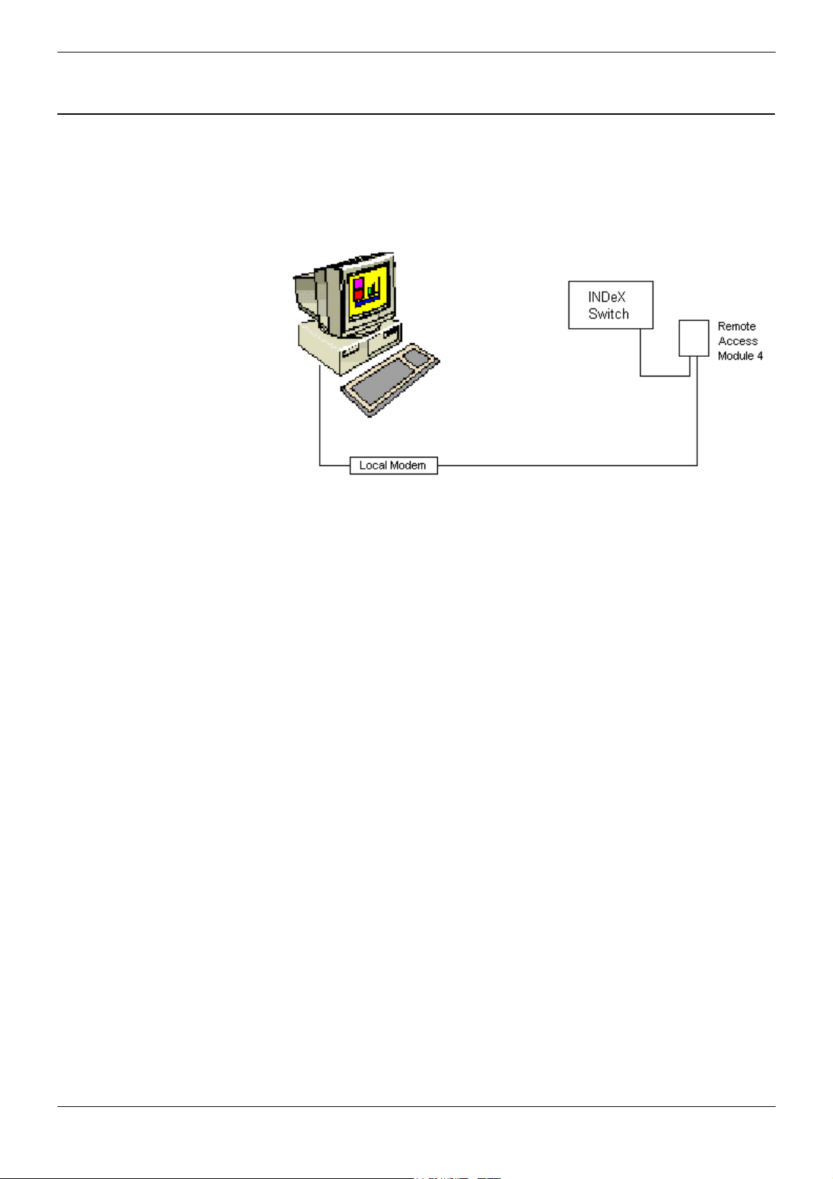
The Remote Access Module (IND-RAM4) kit is used to provide remote
maintenance access to INDeX telephone systems. This guide covers
installation and use with the INDeX telephone system
The IND-RAM4 is factory pre-set to match the default baud rate of the
INDeX system (currently 9600 bps).
– Previous Remote Access Module Kits
This manual covers IND-RAM4 kits based around the ActionTec
modem. For kits based around any other modem refer to the
previous issue of this guide.
User's Guide Page 3
38DHB0002UKDS – Issue 2 (09/01/2002) Remote Access Module 4
Page 4

Security
The IND-RAM4 is a useful tool. It allows remote diagnostics of faults and
often remote correction without the need for a site visit.
However it also allows a direct route into system programming and
administration that could be abused. You must take measures to guard
this route.
You must:
– Keep the direct telephone number of the IND-RAM4 links secure.
This also applies to the INDeX system passwords.
– Keep the INDeX system passwords secure.
Page 4 User's Guide
Remote Access Module 4 38DHB0002UKDS – Issue 2 (09/01/2002)
Page 5
Installation
1. Location Requirements
The Remote Access Module (IND-RAM4) is designed for wall mounting
near the INDeX cabinet containing the CPU Cassette. It requires the
following:
1. A switched and fused mains power socket.
2. A standard direct exchange line master socket
(this allows the IND-RAM4 to operate independent of the INDeX
system's state).
3. A position which leaves the LED indicator lights on the module's
front panel clearly visible.
Rack Systems
Some INDeX systems are installed in a rack.
In this case, the IND-RAM4 can be placed in the base of the rack
(directly below the Control Cabinet).
User's Guide Page 5
38DHB0002UKDS – Issue 2 (09/01/2002) Remote Access Module 4
Page 6

2. Equipment Supplied & Required
Before installing, check that you have all the parts and tools required.
Remote Access Module 4 Kit
– The Remote Access Module (IND-RAM4).
– Internal/External Fax Modem Installation CD.
– Wall brackets (two) plus screws (four).
– Plug top 9v DC power supply
– Telephone line lead (2.5m).
– Serial Lead (0.5m) (for PC connection only – see pages 9 and 11).
– This Remote Access Module 4 User's Guide.
– Other items may be included at Avayas' discretion.
Tools & part Required
– Two No. 6 Pan or Round head screws plus suitable wall plug fixings.
– Drill, drill bits and screw drivers for the fitting of the above items.
– Narrow cross-head screwdriver.
– For on-site programming, a PC with comms/terminal package and 9-
pin serial port.
– Serial Lead (CAB-RAM) supplied with the INDeX CU (for INDeX
system programming).
– KSM Cable supplied with the INDeX IVM Server Cassette (SVRC).
Optional :
– The Remote Access Module provides a socket for a standard
telephone. This can then use the direct exchange line when the
modem is not active.
Page 6 User's Guide
Remote Access Module 4 38DHB0002UKDS – Issue 2 (09/01/2002)
Page 7

3. Attaching the Mounting Brackets
1. Looking at the base of the IND-RAM4 unit, there are four fixing
screws (beneath the four stick-on pads).
Note: Do not remove all of these screws at the same time.
2. Remove two of the pads on one side only, undo and remove the
fixing screws. Use two of the longer supplied screws to attach one of
the mounting brackets (such that the slotted central wall fixing holes
are seen from outside the unit); see the illustration on page 5.
3. Repeat step 2 for the other side of the unit for the remaining
mounting bracket.
User's Guide Page 7
38DHB0002UKDS – Issue 2 (09/01/2002) Remote Access Module 4
Page 8

4. Mounting the Remote Access Module 4
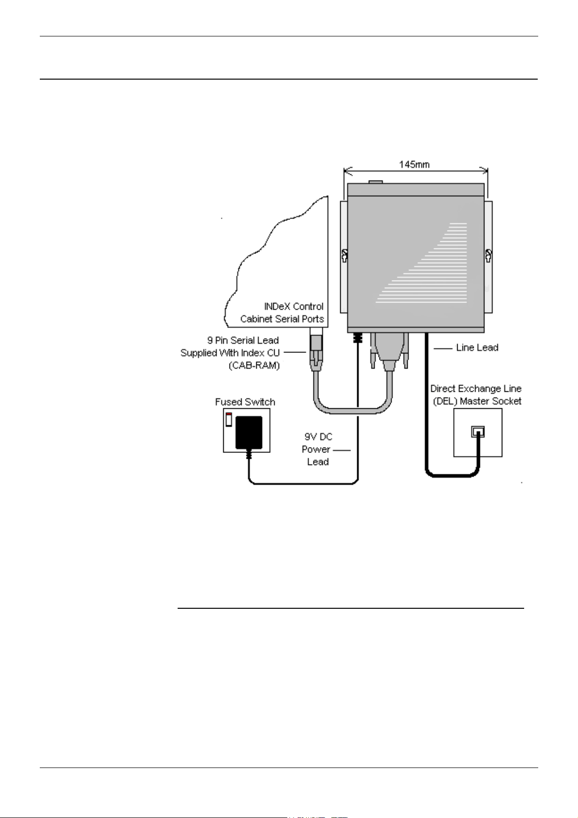
1. Hold the IND-RAM4 unit against the wall in its intended position.
Using the mounting brackets as a template, mark the position of the
fixing hole on each side. These are approximately 145mm apart
horizontally.
2. Drill and insert two wall plugs and then mount the IND-RAM4 unit on
the wall.
3. Connect the serial cable (CAB-RAM) from the units SERIAL
INTERFACE (DTE) socket (25-pin D-type) to one of the
INDeX cabinet's serial ports (9-pin D-types).
– To use the modem link for remote database up and downloads,
you must connect the serial cable to the first INDeX serial port.
4. Connect the line lead from the unit's LINE socket to the direct
exchange line master socket.
– A dedicated direct exchange line must be used to allow the unit
to operate independent of the INDeX system.
5. Plug the output lead of the Plug Top 9V Power Supply into the
female socket and then connect the plug top into a suitable mains
power outlet. When power is applied, press the Power Switch on the
front of the unit and the MR light on the unit will illuminate.
Page 8 User's Guide
Remote Access Module 4 38DHB0002UKDS – Issue 2 (09/01/2002)
Page 9

5. Installing for Use With INDeX IVM/CCM
The following paragraphs provide the details for instruction details for
installation of IND-RAM4 for use with INDeX IVM/CCM. (For details of
Network Support Manager and/or KSM Cable, etc. refer to the IVM/CCM
Installation Manuals).
IVM Server Cassette Installation
To install the IND-RAM4 on the IVM Server Cassette (SVRC) perform
the following.
1. Insert the CD labeled Internal / External Fax Modem Installation in
the CD drive of the Client PC.
2. Using either the NSM (Net Support Manager) or the KSM Cable
connection, connect to the IVM Server Cassette (SVRC) via the
LAN or cable.
3. From the IVM Server Cassette (SVRC), right click on Network
Neighborhood and select Map Network Drive.
4. Browse to network and double click on the ‘ X:\ ‘ drive (where X is
the drive letter of the CD drive of the Client PC) to map the drive.
5. Go to Control Panel and double click on Modems.
6. At the Install New Modem window, tick the box Do not detect my
modem and then click on Next.
7. At the Install New Modem window click on Have Disk.
8. At the Install From Disk window, in the Copy from manufacturers
files from box, type in the route of the mapped CD drive selected at
step 4. E.g. X:\. Click on OK.
9. At the Install New Modem window, from the Manufacturers list
select ACTIONTEC and from Models list select Actiontech 56K Ext
Call Waiting Modem. Click on Next.
10. Select the available COM port (e.g. COM1) from the Install New
Modem window and click Next.
11. When the message You will need to restart your machine …. is
displayed, click on OK then Finish.
12. Close the Modem Properties window. At the message Dial-up
Networking need to be configured …. select NO.
13. Restart the PC and shut down the SVRC manually (by pressing the
red button on the front of the cassette). Restart the SVRC cassette.
User's Guide Page 9
38DHB0002UKDS – Issue 2 (09/01/2002) Remote Access Module 4
Page 10

IVM/CCM Client Installation
To install the IND-RAM4 on the IVM and INDeX CCM Client perform the
following.
1. Insert the CD labeled Internal / External Fax Modem Installation in
the CD drive of the Client PC.
2. Go to Control Panel and double click on Modems.
3. At the Install New Modem window, tick the box Do not detect my
modem and then click on Next.
4. At the Install New Modem window click on Have Disk.
5. At the Install From Disk window, in the Copy from manufacturers
files from box, type in the route of the mapped CD drive selected at
step 4. E.g. X:\. Click on OK.
6. At the Install New Modem window, from the Manufacturers list
select ACTIONTEC and from Models list select Actiontech 56K Ext
Call Waiting Modem. Click on Next.
7. Select the available COM port (e.g. COM1) from the Install New
Modem window and click Next.
8. When the message You will need to restart your machine …. is
displayed, click on OK then Finish.
9. Close the Modem Properties window. At the message Dial-up
Networking need to be configured …. select NO.
10. Restart the PC.
Using IND-RAM4 with IVM and CCM
To use the IND-RAM4 with the IVM Server Cassette (SVRC) and INDeX
CCM Client remotely from the Client PC perform the following.
1. Using the serial cable (0.5m) supplied with the IND-RAM4 kit,
connect the IND-RAM4 to your PC.
2. Ensure that your PC's terminal package is set to 9600bps, 8 bits, no
parity and 1 stop bit.
3. Enter the AT string AT&F and press Enter.
4. Wait for the OK prompt and then enter the AT string AT&W and
press Enter. Wait for the OK prompt.
This restores the default setting for the module.
5. Disconnect the serial cable from the PC and IND-RAM4.
For connection to CCM, use the serial cable (0.5m) supplied with
the kit. For connection to the Server Cassette, use the cable
supplied with the Server cassette.
Page 10 User's Guide
Remote Access Module 4 38DHB0002UKDS – Issue 2 (09/01/2002)
Page 11

6. Restoring INDeX Remote Access Module Defaults
The Remote Access Module is supplied pre-set for operation with an
INDeX system at 9600bps.
To locally restore the Remote Access Module settings :
1. Using the serial cable (0.5m) supplied with the kit, connect the
Remote Access Module to your PC.
2. Ensure that your PC's terminal package is set to 9600bps, 8 bits, no
parity and 1 stop bit.
3. Enter the AT string:
AT&F&D0&K0Q1E0TS0=1 (where 0 = zero).
This sets and stores the preferred settings for INDeX operation as
module Profile 0.
The string can be broken down as follows:
&F Restore factory defaults.
&D0 Ignore DTR.
&K0 Disable DTE flow control.
Q1 Disables results code.
E0 Echo disabled.
T Tone dialling.
S0=1 Answer after first ring.
4. When finished with the local PC connection, enter the AT command
ATE0Q1 to switch of command echo and modem responses.
5. Disconnect the serial cable from the PC and Remote Access
Module. Reconnect the serial cable (CAB-RAM) from the INDeX
cabinet to the Remote Access Module .
User's Guide Page 11
38DHB0002UKDS – Issue 2 (09/01/2002) Remote Access Module 4
Page 12

Performance figures and data quoted in this document are
typical, and must be specifically confirmed in writing by
Avaya before they become applicable to any particular
order or contract. The company reserves the right to make
alterations or amendments to the detailed specifications at
its discretion. The publication of information in this
document does not imply freedom from patent or other
protective rights of Avaya, or others.
Intellectual property related to this product (including
trademarks) and registered to Lucent Technologies has
been transferred or licensed to Avaya.
This document contains propriety information of Avaya and
is not to be disclosed or used except in accordance with
applicable agreements.
Any comments or suggestions regarding this document
should be sent to "gsspublishing@avaya.com".
© Copyright 2002 Avaya
All rights reserved.
Avaya Global SME Solutions
Sterling Court
15 - 21 Mundells
Welwyn Garden City
Hertfordshire
AL7 1LZ
England
Tel: +44 (0) 1707 392200
Fax: +44 (0) 1707 376933
Email: contact@avaya.com
Web: http://www.avaya.com.
Page 12 User's Guide
Remote Access Module 4 38DHB0002UKDS – Issue 2 (09/01/2002)
 Loading...