

Page 1

Configuring Remote
Access
Router Software Version 11.00 Rev. 4n
Site Manager Sofware Version 5.00 Rev. 4n
Part No. 114084 Rev. A
November 1996
Page 2

4401 Great America Parkway 8 Federal Street
Santa Clara, CA 95054 Billerica, MA 01821
Copyright © 1988–1996 Bay Networks, Inc.
All rights reserved. Printed in the USA.November 1996.
The information in this document is subject to change without notice. The statements, configurations, technical data,
and recommendations in this document are believed to be accurate and reliable, but are presented without express or
implied warranty . Users must take full responsibility for their applications of an y products specified in this document.
The information in this document is proprietary to Bay Networks, Inc.
The software described in this document is furnished under a license agreement and may only be used in accordance
with the terms of that license. A summary of the Software License is included in this document.
Restricted Rights Legend
Use, duplication, or disclosure by the United States Government is subject to restrictions as set forth in subparagraph
(c)(1)(ii) of the Rights in Technical Data and Computer Software clause at DFARS 252.227-7013.
Notice for All Other Executive Agencies
Notwithstanding any other license agreement that may pertain to, or accompany the delivery of, this computer
software, the rights of the United States Government regarding its use, reproduction, and disclosure are as set forth in
the Commercial Computer Software-Restricted Rights clause at FAR 52.227-19.
Trademarks of Bay Networks, Inc.
ACE, AFN, AN, BCN, BLN, BN, BNX, CN, FN, FRE, GAME, LN, Optivity, PPX, SynOptics, SynOptics
Communications, W ellfleet and the Wellfleet logo are registered trademarks and Adv anced Remote Node, ANH, ARN,
ASN, Bay•SIS, BayStack, BCNX, BLNX, EZ Install, EZ Internetwork, EZ LAN, PathMan, PhonePlus,
Quick2Config, RouterMan, SPEX, Bay Networks, Bay Networks Press, the Bay Networks logo and the SynOptics
logo are trademarks of Bay Networks, Inc.
Third-Party T rademarks
All other trademarks and registered trademarks are the property of their respective owners.
Statement of Conditions
In the interest of improving internal design, operational function, and/or reliability, Bay Networks, Inc. reserves the
right to make changes to the products described in this document without notice.
Bay Networks, Inc. does not assume any liability that may occur due to the use or application of the product(s) or
circuit layout(s) described herein.
Portions of the code in this software product are Copyright © 1988, Regents of the Univ ersity of California. All rights
reserved. Redistribution and use in source and binary forms of such portions are permitted, provided that the above
copyright notice and this paragraph are duplicated in all such forms and that any documentation, advertising materials,
and other materials related to such distribution and use acknowledge that such portions of the software were
developed by the University of California, Berkeley. The name of the University may not be used to endorse or
promote products derived from such portions of the software without specific prior written permission.
SUCH PORTIONS OF THE SOFTWARE ARE PROVIDED “AS IS” AND WITHOUT ANY EXPRESS OR
IMPLIED WARRANTIES, INCLUDING, WITHOUT LIMITATION, THE IMPLIED WARRANTIES OF
MERCHANTABILITY AND FITNESS FOR A PARTICULAR PURPOSE.
In addition, the program and information contained herein are licensed only pursuant to a license agreement that
contains restrictions on use and disclosure (that may incorporate by reference certain limitations and notices imposed
by third parties).
ii
114084 Rev. A
Page 3

USA Requirements Only
Federal Communications Commission (FCC) Compliance Notice: Radio Frequency Notice
This equipment generates, uses, and can radiate radio-frequency energy. If you do not install and use this equipment
according to the instruction manual, this product may interfere with radio communications. This product has been
tested and found to comply with the limits for a Class A computing device, pursuant to Subpart J of Part 15 of FCC
Rules. Operation is subject to the following two conditions: (1) this device may not cause harmful interference, and
(2) this device must accept any interference received, including interference that may cause undesired operation.
Operating this equipment in a residential area is likely to interfere with radio communications; in which case, the user,
at his/her own expense, must correct the interference.
Shielded-compliant cables must be used with this unit to ensure compliance with the Class A limits.
European Requirements Only
EN 55 022 Declaration of Conformance
This is to certify that the Bay Networks products in this book are shielded against the generation of radio interference
in accordance with the application of Council Directive 89/336/EEC, Article 4a. Conformity is declared by the
application of EN 55 022:1987 Class A (CISPR 22:1985/BS 6527:1988).
This is a Class A product. In a domestic en vironment this product may cause radio interference in which case the user
may be required to take adequate measures.
EN 55 022 Declaration of Conformance
This is to certify that the Bay Networks products in this book are shielded against the generation of radio interference
in accordance with the application of Council Directive 89/336/EEC, Article 4a. Conformity is declared by the
application of EN 55 022:1987 Class B (CISPR 22:1985/BS 6527:1988).
114084 Rev. A
iii
Page 4

Japan/Nippon Requirements Only
Voluntary Control Council for Interference (VCCI) Statement
Voluntary Control Council for Interference (VCCI) Statement
This equipment is in the 1st category (information equipment to be used in commercial and/or industrial areas) and
conforms to the standards set by the Voluntary Control Council for Interference by Data Processing Equipment and
Electronic Office Machines that are aimed at preventing radio interference in commercial and/or industrial areas.
Consequently, when this equipment is used in a residential area or in an adjacent area thereto, radio interference may
be caused to equipment such as radios and TV receivers.
Compliance with the applicable regulations is dependent upon the use of shielded cables. The user is responsible for
procuring the appropriate cables. Read instructions for correct handling.
iv
114084 Rev. A
Page 5

Canada Requirements Only
Canada CS-03 Rules and Regulations
Note:
The Canadian Department of Communications label identifies certified equipment. The certification means that
the equipment meets certain telecommunications network protective operations and safety requirements. The
Department does not guarantee the equipment will operate to the user's satisfaction.
Before installing this equipment, users should ensure that it is permissible to be connected to the facilities of the local
telecommunications company. The equipment must also be installed using an acceptable method of connection. In
some cases, the company's inside wiring associated with a single line individual service may be extended by means of
a certified connector assembly (telephone extension cord). The customer should be aware that compliance with the
above conditions may not prevent the degradation of service in some situations.
Repairs to certified equipment should be made by an authorized Canadian maintenance facility designated by the
supplier. Any repairs or alterations made by the user to this equipment or equipment malfunctions, may give the
telecommunications company cause to request the user to disconnect the equipment.
Users should ensure for their own protection that the electrical ground connections of the power utility, telephone lines
and internal metallic water pipe system, if present, are connected together. This precaution may be particularly
important in rural areas.
Caution:
inspection authority, or electrician, as appropriate.
Canada CS-03 — Règles et règlements
Note:
qu’il respecte certaines exigences de sécurité et de fonctionnement visant les réseaux de télécommunications. Le
ministère ne garantit pas que l’appareillage fonctionnera à la satisfaction de l’utilisateur.
Avant d’installer l’appareillage, s’assurer qu’il peut être branché aux installations du service de télécommunications
local. L’appareillage doit aussi être raccordé selon des méthodes acceptées. Dans certains cas, le câblage interne du
service de télécommunications utilisé pour une ligne individuelle peut être allongé au moyen d’un connecteur certifié
(prolongateur téléphonique). Le client doit toutefois prendre note qu’une telle installation n’assure pas un service
parfait en tout temps.
Les réparations de l’appareillage certifié devraient être confiées à un service d’entretien canadien désigné par le
fournisseur. En cas de réparation ou de modification effectuées par l’utilisateur ou de mauvais fonctionnement de
l’appareillage, le service de télécommunications peut demander le débranchment de l’appareillage.
Pour leur propre sécurité, les utilisateurs devraient s’assurer que les mises à la terre des lignes de distribution
d’électricité, des lignes téléphoniques et de la tuyauterie métallique interne sont raccordées ensemble. Cette mesure de
sécurité est particulièrement importante en milieu rural.
Attention:
aux pouvoirs de réglementation en cause ou à un électricien, selon le cas.
Users should not attempt to make such connections themselves, but should contact the appropriate electric
L’étiquette du ministère des Communications du Canada indique que l’appareillage est certifié, c’est-à-dire
Les utilisateurs ne doivent pas procéder à ces raccordements eux-mêmes mais doivent plutôt faire appel
114084 Rev. A
v
Page 6

Canada Requirements Only
(continued)
D. O. C. Explanatory Notes: Equipment Attachment Limitations
The Canadian Department of Communications label identifies certified equipment. This certification meets certain
telecommunication network protective, operational and safety requirements. The department does not guarantee the
equipment will operate to the users satisfaction.
Before installing the equipment, users should ensure that it is permissible to be connected to the facilities of the local
telecommunications company. The equipment must also be installed using an acceptable method of connection. In
some cases, the company’s inside wiring associated with a single line indi vidual service may be e xtended by means of
a certified connector assembly (telephone extension cord). The customer should be aware that compliance with the
above condition may not prevent degradation of service in some situations.
Repairs to certified equipment should be made by an authorized Canadian maintenance facility designated by the
supplier. Any repairs or alterations made by the user to this equipment, or equipment malfunctions, may give the
telecommunications company cause to request the user to disconnect the equipment.
Users should ensure for their own protection that the electrical ground connections of the power utility, telephone lines
and internal metallic water pipe system, if present, are connected together. This precaution may be particularly
important in rural areas.
Caution:
inspection authority, or electrician, as appropriate.
Users should not attempt to make such connections themselves, but should contact the appropriate electrical
Notes explicatives du ministère des Communications: limites visant les accessoires
L’étiquette du ministère des Communications du Canada indique que l’appareillage est certifié, c’est-à-dire qu’il
respecte certaines exigences de sécurité et de fonctionnement visant les réseaux de télécommunications. Le ministère
ne garantit pas que l’appareillage fonctionnera à la satisfaction de l’utilisateur.
Avant d’installer l’appareillage, s’assurer qu’il peut être branché aux installations du service de télécommunications
local. L’appareillage doit aussi être raccordé selon des méthodes acceptées. Dans certains cas, le câblage interne du
service de télécommunications utilisé pour une ligne individuelle peut être allongé au moyen d’un connecteur certifié
(prolongateur téléphonique). Le client doit toutefois prendre note qu’une telle installation n’assure pas un service
parfait en tout temps.
Les réparations de l’appareillage certifié devraient être confiées à un service d’entretien canadien désigné par le
fournisseur. En cas de réparation ou de modification effectuées par l’utilisateur ou de mauvais fonctionnement de
l’appareillage, le service de télécommunications peut demander le débranchment de l’appareillage.
Pour leur propre sécurité, les utilisateurs devraient s’assurer que les mises à la terre des lignes de distribution
d’électricité, des lignes téléphoniques et de la tuyauterie métallique interne sont raccordées ensemble. Cette mesure de
sécurité est particulièrement importante en milieu rural.
Attention:
aux pouvoirs de réglementation en cause ou à un électricien, selon le cas.
Les utilisateurs ne doivent pas procéder à ces raccordements eux-mêmes mais doivent plutôt faire appel
vi
114084 Rev. A
Page 7

Canada Requirements Only
(continued)
Canadian Department of Communications Radio Interference Regulations
This digital apparatus (Access Feeder Node, Access Link Node, Access Node, Access Stack Node, Backbone
Concentrator Node, Backbone Concentrator Node Switch, Backbone Link Node, Backbone Link Node Switch,
Concentrator Node, Feeder Node, Link Node) does not exceed the Class A limits for radio-noise emissions from
digital apparatus as set out in the Radio Interference Regulations of the Canadian Department of Communications.
Réglement sur le brouillage radioélectrique du ministère des Communications
Cet appareil numérique (Access Feeder Node, Access Link Node, Access Node, Access Stack Node, Backbone
Concentrator Node, Backbone Concentrator Node Switch, Backbone Link Node, Backbone Link Node Switch,
Concentrator Node, Feeder Node, Link Node) respecte les limites de bruits radioélectriques visant les appareils
numériques de classe A prescrites dans le Réglement sur le brouillage radioélectrique du ministère des
Communications du Canada.
114084 Rev. A
vii
Page 8

T1 Service Compliance Statements
T1 Service
NOTE: This T1 Service notice applies to you onl
(MCT1) Link Module (which provides an internal CSU).
This equipment complies with Part 68 of FCC Rules. Please note the following:
1. You are required to request T1 service from the telephone company before you connect the CSU to a T1 network.
When you request T1 service, you must provide the telephone company with the following data:
• The Facility Interface Code
Provide the telephone company with both codes below:
— 04DU9-B (1.544 MB D4 framing format)
— 04DU9-C (1.544 MB ESF format)
The telephone company will select the code it has available.
• The Service Order Code: 6.0F
• The required USOC jack: RJ48C
• The make, model number, and FCC Registration number of the CSU.
2. Your telephone company may make changes to its facilities, equipment, operations, or procedures that could
affect the proper functioning of your equipment. The telephone company will notify you in advance of such
changes to give you an opportunity to maintain uninterrupted telephone service.
3. If your CSU causes harm to the telephone network, the telephone company may temporarily discontinue your
service. If possible, they will notify you in advance, but if advance notice is not practical, you will be notified as
soon as possible and will be informed of your right to file a complaint with the FCC.
4. If you experience trouble with the CSU, please contact Bay Networks Technical Response Center in your area for
service or repairs. Repairs should be performed only by service personnel authorized by Bay Networks, Inc.
United States 1-800-2LAN-WAN
Valbonne, France (33) 92-96-69-68
Sydney , Australia (61) 2-9927-8880
Tokyo, Japan (81) 3-5402-7041
5. You are required to notify the telephone company when you disconnect the CSU from the network and when you
disconnect the BCNX or BLNX from the network.
y if you have received a single or dual port Multi-Channel T1
viii
114084 Rev. A
Page 9

Bay Networks Software License
Note:
This is Bay Networks basic license document. In the absence of a
software license agreement specifying varying terms, this license — or the
license included with the particular product — shall govern licensee’s use of
Bay Networks software.
This Software License shall govern the licensing of all software provided to licensee by Bay Networks (“Software”).
Bay Networks will provide licensee with Software in machine-readable form and related documentation
(“Documentation”). The Software provided under this license is proprietary to Bay Networks and to third parties from
whom Bay Networks has acquired license rights. Bay Networks will not grant any Software license whatsoev er , either
explicitly or implicitly, except by acceptance of an order for either Software or for a Bay Networks product
(“Equipment”) that is packaged with Software. Each such license is subject to the following restrictions:
1. Upon delivery of the Software, Bay Networks grants to licensee a personal, nontransferable, none xclusiv e license
to use the Software with the Equipment with which or for which it was originally acquired, including use at any
of licensee’s facilities to which the Equipment may be transferred, for the useful life of the Equipment unless
earlier terminated by default or cancellation. Use of the Software shall be limited to such Equipment and to such
facility. Software which is licensed for use on hardware not offered by Bay Networks is not subject to restricted
use on any Equipment, however, unless otherwise specified on the Documentation, each licensed copy of such
Software may only be installed on one hardware item at any time.
2. Licensee may use the Software with backup Equipment only if the Equipment with which or for which it was
acquired is inoperative.
3. Licensee may make a single copy of the Software (but not firmware) for safekeeping (archives) or backup
purposes.
4. Licensee may modify Software (but not firmware), or combine it with other software, subject to the provision
that those portions of the resulting software which incorporate Software are subject to the restrictions of this
license. Licensee shall not make the resulting software available for use by any third party.
5. Neither title nor ownership to Software passes to licensee.
6. Licensee shall not provide, or otherwise make available, any Software, in whole or in part, in any form, to any
third party. Third parties do not include consultants, subcontractors, or agents of licensee who have licensee’s
permission to use the Software at licensee’s facility, and who have agreed in writing to use the Software only in
accordance with the restrictions of this license.
7. Third-party owners from whom Bay Networks has acquired license rights to software that is incorporated into
Bay Networks products shall have the right to enforce the provisions of this license against licensee.
8. Licensee shall not remove or obscure any copyright, patent, trademark, trade secret, or similar intellectual
property or restricted rights notice within or affixed to any Software and shall reproduce and affix such notice on
any backup copy of Software or copies of software resulting from modification or combination performed by
licensee as permitted by this license.
114084 Rev. A
ix
Page 10

Bay Networks Software License
9. Licensee shall not reverse assemble, reverse compile, or in any way reverse engineer the Software. [Note: For
licensees in the European Community, the Softw are Directiv e dated 14 May 1991 (as may be amended from time
to time) shall apply for interoperability purposes. Licensee must notify Bay Networks in writing of any such
intended examination of the Software and Bay Networks may provide review and assistance.]
10. Notwithstanding any foregoing terms to the contrary, if licensee licenses the Bay Networks product “Site
Manager,” licensee may duplicate and install the Site Manager product as specified in the Documentation. This
right is granted solely as necessary for use of Site Manager on hardware installed with licensee’s network.
11. This license will automatically terminate upon improper handling of Software, such as by disclosure, or Bay
Networks may terminate this license by written notice to licensee if licensee fails to comply with any of the
material provisions of this license and fails to cure such failure within thirty (30) days after the receipt of written
notice from Bay Networks. Upon termination of this license, licensee shall discontinue all use of the Software
and return the Software and Documentation, including all copies, to Bay Networks.
12. Licensee’s obligations under this license shall survive expiration or termination of this license.
(continued)
x
114084 Rev. A
Page 11

Contents
About This Guide
Before You Begin .............................................................................................................xxi
Where to Find AN, ANH, or ARN Information .................................................................xxii
Conventions ................................................................................................................... xxiii
Acronyms .......................................................................................................................xxiv
Ordering Bay Networks Publications ..............................................................................xxv
Technical Support and Online Services
Bay Networks Customer Service .................................................................................xxviii
Bay Networks Information Services ...............................................................................xxix
World Wide Web ......................................................................................................xxix
Customer Service FTP ............................................................................................xxix
Support Source CD ..................................................................................................xxx
CompuServe ............................................................................................................xxx
InfoFACTS ...............................................................................................................xxxi
How to Get Help ......................................................................................................xxxi
Chapter 1
Understanding Tools and Options
Software Management Tools ..........................................................................................1-1
Router Software ..............................................................................................................1-2
Boot Configuration Options ............................................................................................1-3
The Boot Process ...........................................................................................................1-6
Network Boot ...........................................................................................................1-6
Getting an IP Address .......................................................................................1-6
Getting Kernel Image and Configuration Files .................................................1-10
Local Boot ..............................................................................................................1-12
Configuring the Initial IP Interface ..........................................................................1-13
114084 Rev. A
xi
Page 12

Chapter 2
Selecting the Boot Configuration
Booting the Router for the First Time ..............................................................................2-1
EZ-Install .................................................................................................................. 2-2
Netboot .....................................................................................................................2-2
Local Boot ................................................................................................................2-3
Recommendations ...................................................................................................2-3
Booting the Router Routinely ..........................................................................................2-3
Netboot .....................................................................................................................2-3
Directed Netboot ......................................................................................................2-4
Local Boot ................................................................................................................2-5
Recommendations ...................................................................................................2-5
Completing a Startup Option ..........................................................................................2-6
EZ-Install .................................................................................................................. 2-6
Netboot .....................................................................................................................2-7
Directed Netboot ......................................................................................................2-8
Local Boot ................................................................................................................2-9
Chapter 3
Setting Up a UNIX Boot Server
Setting Up a BOOTP Server ...........................................................................................3-2
Copying the BOOTPD Program on Sun Workstations .............................................3-2
Setting Up BOOTP Sockets .....................................................................................3-2
Setting Up BOOTPD to Run .....................................................................................3-3
Setting Up BOOTPD to Respond to Routers ...........................................................3-3
Editing the bootptab File ....................................................................................3-4
Verifying Consistent BOOTP Service ................................................................3-9
Setting Up a TFTP Server ..............................................................................................3-9
Providing TFTPD Access to the Root Directory .......................................................3-9
Restricting TFTPD Access to a Specified Directory ...............................................3-10
Adding a TFTP User for an HP 9000 .....................................................................3-11
Setting Up Static Routes to Next-Hop Routers ......................................................3-11
Editing the inetd.conf File ................................................................................3-12
Verifying the Routes ........................................................................................3-12
Loading the Changes into Memory ..................................................................3-12
What to Do Next ...........................................................................................................3-13
xii
114084 Rev. A
Page 13

Chapter 4
Configuring Network Booting
Preparing Configuration and Image Files .......................................................................4-2
Creating Configuration Files .....................................................................................4-2
Preparing an Image .................................................................................................4-6
Enabling Netboot or Directed Netboot from Site Manager .............................................4-7
Netboot and Directed Netboot Parameters ..............................................................4-8
Configuring a Netboot or Directed Netboot Interface ...................................................4-11
Netboot Interface Parameters ................................................................................4-14
Setting Up Routing Paths for Netboot ...........................................................................4-16
Enabling Router Interfaces .....................................................................................4-16
Creating BOOTP Relay Agent Forwarding Tables ..................................................4-17
BOOTP Relay Agent Interface Parameters ............................................................4-20
Creating the BOOTP Client Interface Table ..................................................................4-21
BOOTP Client Interface Parameters ......................................................................4-23
Chapter 5
Configuring the Router as a Network Boot Client
Working with a Person at the AN/ANH/ARN Site ...........................................................5-2
Configuring the Router Boot Source ...............................................................................5-2
bconfig Command Format ........................................................................................5-2
bconfig Command Examples ...................................................................................5-3
Configuring the Netboot Interface ...................................................................................5-4
Configuring an IP Synchronous Interface for Network Booting ................................5-4
Configuring an Ethernet Interface for Network Booting ............................................5-6
Configuring a Token Ring Interface for Network Booting ..........................................5-6
Enabling and Disabling Interfaces with ifconfig ........................................................5-7
ifconfig Command Examples ...................................................................................5-8
V erifying Y our Configuration ............................................................................................5-9
What to Do Next ...........................................................................................................5-10
Chapter 6
Managing ANH Repeater Ports
Enabling and Disabling ANH Repeater Ports .................................................................6-1
Testing and Resetting ANH Repeater Ports ...................................................................6-4
Repeater Port Group Parameter Descriptions .........................................................6-5
114084 Rev. A
xiii
Page 14

Chapter 7
Configuring a Data Collection Module
Ethernet DCM and RMON Overview ..............................................................................7-1
Remote Network Monitoring (RMON) ......................................................................7-2
The RMON Groups ..................................................................................................7-3
Ethernet Statistics Group ...................................................................................7-3
History Control Group and Ethernet History Group ...........................................7-4
Host Group ........................................................................................................7-4
HostTopN Group ................................................................................................7-4
Matrix Group ......................................................................................................7-4
Filter Group ........................................................................................................7-4
Packet Capture Group .......................................................................................7-5
Alarm Group ......................................................................................................7-5
Event Group .......................................................................................................7-5
For More Information about RMON ..........................................................................7-5
Enabling a DCM Using Site Manager .............................................................................7-6
DCM Global Parameter Descriptions .......................................................................7-7
Managing the DCM Using Site Manager ......................................................................7-11
Activating the DCM ................................................................................................7-12
Disabling the DCM .................................................................................................7-12
Booting the DCM ....................................................................................................7-13
Changing the DCM Configuration Parameters .......................................................7-13
Deleting the DCM Software Subsystem .................................................................7-14
Managing the DCM Using the Technician Interface ......................................................7-15
Changing DCM Configuration Parameters .............................................................7-15
RMON Implementation Notes .......................................................................................7-16
RMON Applications ................................................................................................7-17
RMON Memory Use ...............................................................................................7-18
Interoperability Issues and Memory Use for RMON Groups ..................................7-18
Statistics Group ...............................................................................................7-19
History Group ..................................................................................................7-19
Host Group ......................................................................................................7-20
HostTopN Group ..............................................................................................7-21
Matrix Group ....................................................................................................7-21
Filter and Capture Groups ...............................................................................7-22
xiv
114084 Rev. A
Page 15

Alarm and Event Group ...................................................................................7-23
Appendix A
Troubleshooting Network Boot Problems
Solving Startup Problems .............................................................................................. A-1
Router Fails to Get IP Address ............................................................................... A-2
Upstream Router Not Receiving BOOTP Requests ......................................... A-2
Upstream Router Not Sending BOOTP Responses ......................................... A-2
Router Fails to Netboot ........................................................................................... A-3
Upstream Router Not Receiving BOOTP Requests ......................................... A-3
Router Not Sending BOOTP Responses .......................................................... A-4
BOOTP Server Not Sending BOOTP Responses ............................................ A-4
Router Fails to Perform Directed Netboot ............................................................... A-5
Router Netboots, but Fails to Load Applications ..................................................... A-5
Identifying Remote Connectivity Problems .................................................................... A-8
Displaying Messages from the AN/ANH/ARN Console ........................................... A-8
Displaying Statistics and Error Messages ............................................................... A-8
Guidelines for Using Packet Capture ...................................................................... A-9
Guidelines for Using a LAN Protocol Analyzer ........................................................ A-9
Resolving Connectivity Problems ................................................................................ A-10
Displaying Parameter Settings .............................................................................. A-10
Debugging the BOOTP Server .............................................................................. A-12
Verifying the BOOTP Server Setup ....................................................................... A-13
Displaying the BOOTP Server’s IP Routes ........................................................... A-15
Displaying the Number of Packets Forwarded and Dropped ................................ A-15
Quick Get Instructions .................................................................................... A-16
Technician Interface Instructions .................................................................... A-16
Maintaining the Router Software ................................................................................. A-16
Upgrading the Software Image ............................................................................. A-17
Restoring a Local File System .............................................................................. A-17
Appendix B
Using the Local Boot Procedure
What Is Quick-Start? ..................................................................................................... B-1
Using the Worksheets .................................................................................................... B-2
Global Information Worksheet ................................................................................. B-3
114084 Rev. A
xv
Page 16

Router Protocol Worksheets ................................................................................... B-6
Wide Area Protocol Worksheets ........................................................................... B-10
Running the Quick-Start Script .................................................................................... B-14
Appendix C
Implementation Notes
Hints .............................................................................................................................. C-1
Notes ............................................................................................................................. C-2
Network Configuration Options ......................................................................................C-3
Ensuring Ethernet Network Compliance .................................................................C-3
Network Path Containing Three Repeaters ...................................................... C-4
Network Path Containing Four Repeaters ........................................................C-4
Configuring a Single ANH .......................................................................................C-4
Configuring Multiple Hubs .......................................................................................C-6
Configuring an AUI Port .......................................................................................... C-7
Connecting the AUI Port to a Fiber Optic Backbone .........................................C-8
Connecting the AUI Port to a Coaxial Backbone ..............................................C-9
Index
xvi
114084 Rev. A
Page 17

Figures
Figure 1-1. Getting an IP Address from a Bay Networks Standard Circuit or a Frame Relay
PVC in Direct Access Mode 1-8
Figure 1-2. Getting an Address from a PVC in Group Access Mode .........................1-9
Figure 1-3. Getting the Pathnames of the Kernel and Configuration Files ...............1-10
Figure 1-4. Getting the Configuration File ................................................................1-11
Figure 1-5. Getting the Kernel ..................................................................................1-12
Figure 1-6. Establishing an IP Network Interface .....................................................1-13
Figure 3-1. Sample bootptab File ...............................................................................3-8
Figure 4-1. Edit Netboot Global Parameters Window .................................................4-7
Figure 4-2. Netboot Interfaces Window ....................................................................4-11
Figure 4-3. Netboot Interface Window ......................................................................4-12
Figure 4-4. Netboot Interfaces Window ....................................................................4-13
Figure 4-5. Enabling BOOTP in a Sample Network .................................................4-16
Figure 4-6. BOOTP Relay Agent Interface Table Window ........................................4-18
Figure 4-7. BOOTP Relay Agent Forwarding Table Window ....................................4-19
Figure 4-8. BOOTP Addresses Window ...................................................................4-19
Figure 4-9. BOOTP Client Interface Table Window ..................................................4-22
Figure 4-10. BOOTP Client Interface Address Window ..............................................4-22
Figure 6-1. 8-Port ANH Port Status Window ..............................................................6-2
Figure 6-2. 12-Port ANH Port Status Window ............................................................6-3
Figure 6-3. Group Parameters Window ......................................................................6-4
Figure 7-1. Edit Base Module DCM Parameters Window ..........................................7-6
Figure 7-2. Edit Base Module DCM Parameters Window ........................................7-13
Figure B-1. Starting the IP Interface Test ................................................................. B-16
Figure C-1. Typical Single-ANH Configuration ...........................................................C-5
Figure C-2. Connecting the ANH with Other Hubs ....................................................C-7
Figure C-3. Connecting Two ANH Systems Using 10Base-FL Transceivers ..............C-8
Figure C-4. Connecting ANH Systems through a Coaxial Backbone ........................C-9
114084 Rev. A
xvii
Page 18

Page 19

Tables
Table 1-1. Summary of Boot Options ........................................................................1-4
Table 3-1. BOOTPD Tags for a Router Hostname ....................................................3-5
Table 3-2. BOOTPD Tags for a Boot Image Name ...................................................3-6
Table 3-3. Providing TFTPD Access to Root and All Subdirectories ......................3-10
Table 3-4. Restricting TFTPD Access to One Directory ..........................................3-10
Table 4-1. BayStack AN Configurations ....................................................................4-3
Table 4-2. BayStack ANH Configurations .................................................................4-4
Table 4-3. BayStack ARN Base Module Configurations ...........................................4-5
Table 4-4. BayStack ARN Expansion Module Configurations ...................................4-5
Table 4-5. BayStack ARN Adapter Module Configurations .......................................4-5
Table 5-1. bconfig Command Settings ......................................................................5-3
Table 5-2. ifconfig Command Settings for a Synchronous Interface .........................5-5
Table 5-3. ifconfig Command Settings for an Ethernet Interface ..............................5-6
Table 5-4. ifconfig Command Settings for a Token Ring Interface ............................5-7
Table 5-5. ifconfig Settings to Enable and Disable Netboot Interfaces .....................5-8
Table 7-1. DRAM and RMON Memory Size ...........................................................7-18
Table 7-2. Maximum Number of Hosts ...................................................................7-20
Table 7-3. Default Size for Capture Buffer ..............................................................7-22
Table A-1. BOOTP Messages ................................................................................ A-13
Table B-1. Quick-Start/Power-Start Commands ..................................................... B-15
Table C-1. IEEE 802.3 Maximum Segment Links ....................................................C-4
114084 Rev. A
xix
Page 20

Page 21

About This Guide
Read this guide if you are responsible for connecting a Bay Networks™
BayStack™ Access Node (AN®), Access Node Hub (ANH™), or Advanced
Remote Node (ARN™) router to a managed network.
This guide offers
• An overview of AN, ANH, and ARN software (Chapter 1)
• A description of network booting (Chapter 2)
• Instructions for setting up a UNIX
(Chapter 3)
• Instructions for configuring Site Manager to support network booting
(Chapter 4)
• Instructions for configuring the router for network booting (Chapter 5)
• Instructions for managing ANH repeater ports (Chapter 6)
• Instructions for configuring an Ethernet Data Collection Module (DCM) for
RMON statistics gathering (Chapter 7)
• Troubleshooting guidelines and procedures (Appendix A)
• Worksheets for completing the installation procedure (Appendix B)
• Implementation hints and notes (Appendix C)
workstation as a BOOTP server
Before Y ou Begin
Before using this guide, you (or a person at the router site) must install the router,
or hardware and network connections, as described in one of the following guides:
• Installing and Operating BayStack AN and ANH Systems
• Installing and Operating BayStack ARN Routers
114084 Rev. A
xxi
Page 22

Configuring Remote Access
Where to Find AN, ANH, or ARN Information
Use this guide in conjunction with other Bay Networks documentation to set up
and manage AN, ANH, and ARN systems. Refer to the following when looking
for specific information.
For Information on This Look Here
Installing BayStack AN or ANH
hardware
Installing BayStack Advanced Remote
Node hardware
Learning about AN, ANH, and ARN
software and the four startup/boot
options
Choosing a startup option for the router Chapter 2 in this guide
Setting up a UNIX workstation as a
BOOTP server to support a network
boot option
Configuring Site Manager to support a
network boot option
What to do at the AN/ANH/ARN site to
support a network boot option
Configuring a Data Collection Module Chapter 7 in this guide
Preparing for the Quick-Start (local boot)
procedure
Completing any of the four startup
options at the AN/ANH/ARN site
Configuring and managing an
AN/ANH/ARN after it is connected to the
network
Reconfiguring AN/ANH/ARN netboot
interfaces
Considerations for setting up an
AN/ANH/ARN
Resolving problems with the network
boot process
Troubleshooting all other problems
Installing and Operating BayStack AN and ANH
Systems
Installing and Operating BayStack ARN
Routers
Chapter 1 in this guide
Chapter 3 in this guide
Chapter 4 in this guide
Chapter 5 in this guide
Appendix B in this guide
Installing and Operating BayStack AN and ANH
Systems
ARN Routers
Configuring Routers
and BNX Platforms
Chapter 5 in this guide
Appendix C in this guide
Appendix A in this guide
Troubleshooting Routers
or
Installing and Operating BayStack
and
Managing Routers
xxii
114084 Rev. A
Page 23

.
Conventions
angle brackets (< >) Indicate that you choose the text to enter based on the
About This Guide
description inside the brackets. Do not type the
brackets when entering the command.
ping
Example: if command syntax is
you enter
ping 192.32.10.12
<ip_address>
,
bold text
Indicates text that you need to enter, command names,
and buttons in menu paths.
Example: Enter
Example: Use the
Example: ATM DXI > Interfaces >
wfsm &
dinfo
command.
PVCs
identifies the
PVCs button in the window that appears when you
select the Interfaces option from the ATM DXI menu.
brackets ([ ]) Indicate optional elements. You can choose none, one,
or all of the options.
.
ellipsis points Horizontal (. . .) and vertical ellipsis points indicate
()
.
omitted information.
italic text
Indicates variable values in command syntax
descriptions, new terms, file and directory names, and
book titles.
quotation marks (“ ”) Indicate the title of a chapter or section within a book.
separator ( > ) Separates menu and option names in instructions and
internal pin-to-pin wire connections.
Example: Protocols > AppleTalk identifies the
AppleTalk option in the Protocols menu.
Example: Pin 7 > 19 > 20
screen text
Indicates data that appears on the screen.
Example:
Set Bay Networks Trap Monitor Filters
vertical line (|) Indicates that you enter only one of the parts of the
command. The vertical line separates choices. Do not
type the vertical line when entering the command.
Example: If the command syntax is
show at routes
show at routes
114084 Rev. A
nets
|
, you enter either
show at nets
or
, but not both.
xxiii
Page 24

Configuring Remote Access
Acronyms
ANSI American National Standards Institute
ARP Address Resolution Protocol
AUI Attachment Unit Interface
BOFL Breath of Life
BOOTP Bootstrap Protocol
BOOTPD Boot Protocol Daemon
BRI Basic Rate Interface
CHAP Challenge Handshake Authentication Protocol
DCE data communications equipment
DCM Data Collection Module
DLCI data link connection identifier
DLCMI Data Link Control Management Interface
DTE data terminal equipment
FTP File Transfer Protocol
HDLC high-level data link control
IEEE Institute of Electrical and Electronic Engineers
IP Internet Protocol
IPX Internet Packet Exchange
ISDN Integrated Services Digital Network
LMI Local Management Interface
LQR Link Quality Reporting
MAC media access control
MAU media access unit
MIB management information base
MTU maximum transmission unit
NBMA nonbroadcast multi-access
NMM network management module
OSPF Open Shortest Path First Protocol
P AP Password Authentication Protocol
PPP Point-to-Point Protocol
PVC permanent virtual circuit
RARP Reverse Address Resolution Protocol
xxiv
114084 Rev. A
Page 25

RFC Request for Comments
RIP Routing Information Protocol
RMON remote monitoring
SAM System Administration Manager
SMDS switched multimegabit data service
SMIT System Management Interface Tool
SNMP Simple Network Management Protocol
TCP/IP Transmission Control Protocol/Internet Protocol
Telnet Telecommunication Network
TFTP Trivial File Transfer Protocol
TFTPD Trivial File Transfer Protocol Daemon
UDP User Datagram Protocol
UTP unshielded twisted-pair
Ordering Bay Networks Publications
To purchase additional copies of this document or other Bay Networks
publications, order by part number from the Bay Networks Press
telephone or fax numbers:
About This Guide
™
at the following
114084 Rev. A
• Telephone - U.S./Canada 1-888-4BAYPRESS
• Telephone - International 1-510-490-4752
• Fax 1-510-498-2609
You can also use these numbers to request a free catalog of Bay Networks Press
product publications.
xxv
Page 26

Page 27

Technical Support and Online Services
To ensure comprehensive network support to our customers and partners
worldwide, Bay Networks Customer Service has Technical Response Centers
in key locations around the globe:
• Billerica, Massachusetts
• Santa Clara, California
• Sydney, Australia
• Tokyo, Japan
• Valbonne, France
The Technical Response Centers are connected via a redundant Frame Relay
Network to a Common Problem Resolution system, enabling them to transmit and
share information, and to provide live, around-the-clock support 365 days a year.
Bay Networks Information Services complement the Bay Networks Service
program portfolio by giving customers and partners access to the most current
technical and support information through a choice of access/retrieval means.
These include the World W ide Web, CompuServ e, Support Source CD, Customer
Support FTP, and InfoFACTS document fax service.
114084 Rev. A xxvii
Page 28

Configuring Remote Access
Bay Networks Customer Service
If you purchased your Bay Networks product from a distributor or authorized
reseller, contact that distributor’s or reseller’s technical support staf f for assistance
with installation, configuration, troubleshooting, or integration issues.
Customers can also purchase direct support from Bay Networks through a variety
of service programs. As part of our PhonePlus™ program, Bay Netw orks Service
sets the industry standard, with 24-hour, 7-days-a-week telephone support
available worldwide at no extra cost. Our complete range of contract and
noncontract services also includes equipment staging and integration, installation
support, on-site services, and replacement parts delivery -- within approximately
4 hours.
To purchase any of the Bay Networks support programs, or if you have questions
on program features, use the following numbers:
Region Telephone Number Fax Number
United States and
Canada
1-800-2LANWAN; enter Express Routing
Code (ERC) 290 when prompted
(508) 670-8766
(508) 436-8880 (direct)
Europe (33) 92-968-300 (33) 92-968-301
Asia/Pacific Region (612) 9927-8800 (612) 9927-8811
Latin America (407) 997-1713 (407) 997-1714
In addition, you can receive information on support programs from your local
Bay Networks field sales office, or purchase Bay Networks support directly
from your authorized partner.
xxviii 114084 Rev. A
Page 29

Bay Networks Information Services
Bay Networks Information Services provide up-to-date support information as a
first-line resource for network administration, expansion, and maintenance. This
information is available from a variety of sources.
W orld Wide Web
The Bay Networks Customer Support Web Server offers a diverse library of
technical documents, software agents, and other important technical information
to Bay Networks customers and partners.
A special benefit for contracted customers and resellers is the ability to access the
Web Server to perform Case Management. This feature enables your support staff
to interact directly with the network experts in our worldwide Technical Response
Centers. A registered contact with a valid Site ID can
• View a listing of support cases and determine the current status of any open
case. Case history data includes severity designation, and telephone, e-mail,
or other logs associated with the case.
Technical Support and Online Services
• Customize the listing of cases according to a variety of criteria, including
date, severity, status, and case ID.
• Log notes to existing open cases.
• Create new cases for rapid, efficient handling of noncritical network
situations.
• Communicate directly via e-mail with the specific technical resources
assigned to your case.
The Bay Networks URL is http://www.baynetworks.com. Customer Service is a
menu item on that home page.
Customer Service FTP
Accessible via URL ftp://support.baynetworks.com (134.177.3.26), this site
combines and organizes support files and documentation from across the
Bay Networks product suite, including switching products from our Centillion™
®
and Xylogics
site lets you quickly locate information on any of your Bay Networks products.
114084 Rev. A xxix
business units. Central management and sponsorship of this FTP
Page 30

Configuring Remote Access
Support Source CD
This CD-ROM -- sent quarterly to all contracted customers -- is a complete Bay
Networks Service troubleshooting knowledge database with an intelligent text
search engine.
The Support Source CD contains extracts from our problem-tracking database;
information from the Bay Networks Forum on CompuServe; comprehensive
technical documentation, such as Customer Support Bulletins, Release Notes,
software patches and fixes; and complete information on all Bay Networks
Service programs.
You can run a single version on Macintosh Windows 3.1, Windows 95,
Windows NT, DOS, or UNIX computing platforms. A Web links feature enables
you to go directly from the CD to various Bay Networks Web pages.
CompuServe
For assistance with noncritical network support issues, Bay Networks Information
Services maintain an active forum on CompuServe, a global bulletin-board
system. This forum provides file services, technology conferences, and a message
section to get assistance from other users.
The message section is monitored by Bay Networks engineers, who provide
assistance wherever possible. Customers and resellers holding Bay Networks
service contracts also have access to special libraries for advanced levels of
support documentation and software. To take advantage of CompuServe’ s recently
enhanced menu options, the Bay Networks Forum has been re-engineered to allow
links to our Web sites and FTP sites.
We recommend the use of CompuServe Information Manager software to access
these Bay Networks Information Services resources. To open an account and
receive a local dial-up number in the United States, call CompuServe at
1-800-524-3388. Outside the United States, call 1-614-529-1349, or your nearest
CompuServe office. Ask for Representative No. 591. When you are on line with
your CompuServe account, you can reach us with the command
xxx 114084 Rev. A
GO BAYNET.
Page 31

InfoFACTS
InfoFACTS is the Bay Networks free 24-hour fax-on-demand service. This
automated system has libraries of technical and product documents designed to
help you manage and troubleshoot your Bay Networks products. The system
responds to a fax from the caller or to a third party within minutes of being
accessed.
To use InfoFACTS in the United States or Canada, call toll-free 1-800-786-3228.
Outside North America, toll calls can be made to 1-408-764-1002. In Europe,
toll-free numbers are also available for contacting both InfoFACTS and
CompuServe. Please check our Web page for the listing in your country.
How to Get Help
Use the following numbers to reach your Bay Networks Technical Response
Center:
Technical Response Center Telephone Number Fax Number
Billerica, MA 1-800-2LANWAN (508) 670-8765
Santa Clara, CA 1-800-2LANWAN (408) 764-1188
Valbonne, France (33) 92-968-968 (33) 92-966-998
Sydney, Australia (612) 9927-8800 (612) 9927-8811
Tokyo, Japan (81) 3-5402-0180 (81) 3-5402-0173
Technical Support and Online Services
114084 Rev. A xxxi
Page 32

Page 33

Chapter 1
Understanding Tools and Options
The Bay Networks BayStack ARN and AN families of routers connect
multiprotocol workgroups to corporate backbone networks. This chapter provides
an overview of the software tools and options for configuring remote access. The
chapter includes information about the following:
• Software management tools
• Router software
• Boot configuration options
• Boot process
Software Management Tools
You configure and manage an AN, ANH, or ARN using
• The graphical, SNMP-based router management tools within
Optivity Internetwork™, a component of the Bay Networks
Optivity Enterprise™ application suite:
-- Site Manager, a router management, configuration, and monitoring
application.
-- RouterMan™, a real-time router performance and status reporting
appplication.
-- PathMan™, a diagnostic application for determining the complete data
path between any two network devices.
• The Technician Interface, a terminal-based command-line interface that
operates in router memory. Technician Interface commands and scripts
provide real-time SNMP-based MIB access from an attached or remote
(modem or Telnet) console connection.
114084 Rev. A 1-1
Page 34

Configuring Remote Access
• A firmware diagnostics monitor with a command-line interface. You use the
AN/ANH/ARN monitor to configure the router’s boot configuration.
This manual describes how to configure the router’s boot configuration using the
Diagnostic Monitor and Technician Interface, and how to connect remote access
systems to a managed network using Site Manager.
Router Software
Before it can operate, the AN, ANH, or ARN hardware must boot a software
image. The software image is a group of executable files that operate the protocols
that the network requires. The AN/ANH software image is called an.exe. The
ARN software image is called arn.exe. The software image comprises the
following executable startup files:
•A krnl_an.exe file (for the AN/ANH) or krnl_arn.exe (for the ARN) that
contains the operating system kernel.
• Application files -- executable files needed to perform the functions specified
in the configuration file. All application files have .exe filename extensions.
(For example, the router needs an ipx.exe executable file to run IPX.)
• String files -- compressed ASCII files needed when you use the Technician
Interface to display the event log or management information base (MIB)
object names. Groups of string files remain in compressed format within the
an.exe or arn.exe file until needed.
To bridge and route traffic, the AN, ANH, or ARN also needs a configuration file
that is tailored to your network. A configuration file is a binary system file that
contains hardware and software configuration data. The default configuration file
is named config.
1-2 114084 Rev. A
Page 35

Boot Configuration Options
This section summarizes your options for getting the AN, ANH, or ARN software
image and configuration files.
Note: If you plan to use the Quick2Config™ software to configure the AN or
ANH, see Configuring Your Router Using the Quick2Config Tool.
Quick2Config is a Microsoft Windows-based application that you can use to
create or modify router configuration files.
An AN/ANH/ARN boots using one of four configured startup options. The
differences among the four startup options are based on whether the router
retrieves software image and configuration files over the network or from local
memory.
Getting a software image or configuration file over the network is called
Netbooting. Getting a file from the file system stored in local Flash memory is
called Local booting.
Understanding Tools and Options
To initially start up the AN, ANH, or ARN, you use one of these boot
configuration options:
• EZ-Install (the default)
• Netboot
• Local Boot
To start up the AN, ANH, or ARN after the initial configuration, you use one of
these options:
• Netboot
• Directed Netboot
• Local Boot
114084 Rev. A 1-3
Page 36

Configuring Remote Access
Table 1-1 summarizes the four startup options. The next section, “The Boot
Process,” describes how each option works.
Table 1-1. Summary of Boot Options
Source for
Boot
Option
Software
Image
Source for
config File Description and Requirements
EZ-Install Local
(Flash memory)
Netboot Network
(Serial,
Ethernet, or
Token Ring*
connection)
Network
(Serial
connection)
Network
(Serial,
Ethernet, or
Token Ring*
connection)
The default option. The router boots from a software image
in local memory, and then transmits a request for its IP
address and configuration file through an attached serial
interface.
Next, a remote UNIX- or DOS-based workstation that is
configured as a Boot Protocol (BOOTP) server downloads a
customized configuration file; you save that configuration to
Flash memory.
Requires a communications link over an HDLC or Frame
Relay interface.
If EZ-Install fails, the router tries the Local Boot procedure.
The router obtains all startup files from a remote UNIX- or
DOS-based workstation that is configured as a BOOTP
server. (Getting these files individually, rather than getting
the entire
usage and prevents saturation of the router’s memory.)
Requires a local
file (for the ARN), a local console connection, and a
communications link over an HDLC , F r ame Rela y, Ethernet,
or (for the ARN)Token Ring* interface.
If Netboot fails, the router tries the Local Boot procedure.
an.exe
or
arn.exe
file, minimizes the cost of line
an.exe
file (for the AN or ANH) or
arn.exe
(continued)
1-4 114084 Rev. A
Page 37

Understanding Tools and Options
Table 1-1. Summary of Boot Options
Source for
Boot
Option
Directed
Netboot
Local
Boot
Software
Image
Network
(Serial,
Ethernet, or
Token Ring*
connection)
Local
(Flash memory)
Source for
config File Description and Requirements
Network
(Serial,
Ethernet, or
Token Ring*
connection)
Local
(Flash memory)
(continued)
The router obtains all startup files from a remote UNIX- or
DOS-based workstation that is configured as a Trivial File
Transfer Protocol (TFTP) server. You specify the IP address
of the TFTP server and the pathname of the startup files
before booting.
Requires a local
file (for the ARN), a local console connection, and a
communications link over an HDLC , F r ame Rela y, Ethernet,
or Token Ring* interface.
If Directed Netboot cannot retrieve the appropriate files, the
router attempts normal Netboot. If this fails, the router tries
Local Boot.
The router boots using a software router image and
configuration file stored in local memory.
During the initial startup, the router uses a generic startup
configuration file. You customize the default configuration
file by assigning an IP address to an interface and running
an installation script; this is called the
procedure.
an.exe
file (for the AN or ANH) or
Quick-Start
arn.exe
Quick-Start requires a local console and an active IP
network connection.
*. You can use the Netboot and Directed Netboot procedure on a Token Ring interface on the ARN only.
114084 Rev. A 1-5
Page 38

Configuring Remote Access
The Boot Process
An AN, ANH, or ARN boots using its configured startup option. The default
configuration is EZ-Install.
(If an initial boot attempt fails on an AN or ANH, the router attempts to boot once
using a different option. If both boot attempts fail, you must troubleshoot the
problem and reboot the router as described in Appendix A. If an initial boot
attempt fails on an ARN, the router first tries to local boot, and then netboot. The
ARN continues attempts to local boot and netboot until it successfully boots.)
The following sections describe the boot process for network and local boot
options.
Network Boot
When booting over the network using EZ-Install, Netboot, or Directed Netboot,
the router essentially
1. Powers on.
2. Determines its IP address.
3. Obtains a software kernel file and/or configuration file by communicating
with a configured BOOTP server on the IP network.
4. Reboots, using the newly transferred image.
5. Gets application and string files over the network as it needs them.
6. Begins bridging and routing network traffic in accordance with the
configuration file.
The following sections describe in more detail the key steps in this process:
obtaining an IP address and downloading the image and configuration files.
Getting an IP Address
For Netboot and Directed Netboot, you configure the IP address manually.
Chapter 4 describes how to use Site Manager to configure Netboot interfaces.
Chapter 5 describes how to configure the netboot interfaces using the Technician
Interface.
1-6 114084 Rev. A
Page 39

Understanding Tools and Options
During the EZ-Install process, the router obtains its address automatically, as
described next.
1. When you power on the router, it runs a set of diagnostic tests.
2. The router sends a BOOTP request to the upstream router for an IP address
and subnet mask.
Note: The upstream router must have a circuit running Bay Networks
Standard Point-to-Point Protocol (PPP) using HDLC or a Frame Relay
permanent virtual circuit (PVC).
The AN, ANH, or ARN issues the request through all serial ports at about the
same time, even if cables are not connected to these ports. Each port
successively tries the following protocols until it receives a response:
• Bay Networks Standard PPP using HDLC (high-level data link control)
encapsulation
• Frame Relay Annex D
• Frame Relay Local Management Interface (LMI)
• Frame Relay Annex A
The AN, ANH, or ARN makes tw o attempts for each protocol ov er each serial
interface. If one does not receive a response in approximately 4 minutes, the
router boots the image and configuration file in its local file system, as
described in the next section, “Local Boot
.”
3. The first interface on the upstream router to receive the BOOTP request
responds.
4. The upstream router calculates the IP address of the AN/ANH’s serial
interface.
The upstream router calculates the IP address based on its protocol
configuration. See Step a if the upstream router circuit is running Bay
Networks Standard or is a Frame Relay PVC in direct access mode. See Step
b if it is a Frame Relay PVC in group access mode.
a. A PVC in direct access mode or a Bay Networks Standard interface
calculates the IP address by adding 1 to the IP address of the interface that
received the request.
114084 Rev. A 1-7
Page 40

Configuring Remote Access
For example, in Figure 1-1 the upstream router’s interface address is
192.32.1.1. This means that the upstream router calculates 192.32.1.2 as
the booting router’s IP interface.
AN/ANH/ARN router
BOOTP request
Upstream router
IP address 192.32.1.1
BOOTP response with
IP address 192.32.1.2
NPA0001A
Figure 1-1. Getting an IP Address from a Bay Netw orks Standard Circuit
or a Frame Relay PVC in Direct Access Mode
Note: If the IP address plus 1 equals a broadcast address, the upstream router
calculates the IP address by subtracting 1. For example, if its interface is
7.255.255.254, the IP interface for the booting router is 7.255.255.253.
b. A PVC in group access mode references its BOOTP client interface table
to find an associated IP address for the booting router.
Note: The BOOTP client interface table contains a data link connection
identifier (DLCI) and IP address pair for each PVC. You use Site Manager to
create this table when you follow the instructions for setting up routing paths
in Chapter 4.
1-8 114084 Rev. A
Page 41

Understanding Tools and Options
For example, in Figure 1-2, an AN/ANH/ARN router sends BOOTP
requests for its IP address. The upstream router receives the request on
PVC 31. The upstream router determines the DLCI, refers to DLCI 31 in
the BOOTP client interface table, finds the IP address, and sends a
BOOTP response containing the IP address back to PVC 31.
AN/ANH/ARN
Circuit containing PVC 31, 32, 33 (for
virtual connections to the three routers)
Key
BOOTP request
BOOTP response
Booting router 2 Booting router 3
PVC 32
PVC 31
Frame Relay
Upstream router
PVC 33
BOOTP Client Interface Table:
DLCI 31 192.32.1.2
DLCI 32 192.32.1.3
DLCI 33 192.32.1.4
NPA0002A
Figure 1-2. Getting an Address from a PVC in Group Access Mode
5. The upstream router sends the IP address and subnet mask to the
AN/ANH/ARN in a BOOTP response message.
6. The AN/ANH/ARN assigns the IP address and subnet mask to any serial
interface that receives a BOOTP response.
7. The AN/ANH/ARN stores these addresses, along with the address of the
next-hop router, in RAM.
114084 Rev. A 1-9
Page 42

Configuring Remote Access
If both serial interfaces receive BOOTP responses, the AN/ANH/ARN
assigns the respective IP addresses to each interface.
Getting Kernel Image and Configuration Files
With a known IP address, the AN/ANH/ARN can get image and configuration
files.
1. The AN/ANH/ARN sends a BOOTP request for the pathnames of a
configuration file and image kernel.
The router issues the request simultaneously through all serial (COM),
Ethernet, and Token Ring (ARN only) interfaces that have IP addresses. It
issues this request periodically for about 3 minutes, regardless of whether a
cable is connected.
2. A BOOTP server responds to the router’s request with the directory
pathnames (F
AN/ANH/ARN
igure 1-3).
Upstream router
Pathnames
Corporate backbone
BOOTP
server
Key
BOOTP request
BOOTP response
NPA0003A
Figure 1-3. Getting the Pathnames of the Kernel and Configuration Files
The first router interface that processes the BOOTP response acts as the TFTP
client in the remaining steps.
1-10 114084 Rev. A
Page 43

Understanding Tools and Options
3. The AN/ANH/ARN stops sending BOOTP requests.
4. The AN/ANH/ARN sends a TFTP request for the configuration file.
5. The BOOTP server uses TFTP to transfer the configuration file (F
AN/ANH/ARN
Configuration file
Corporate backbone
Upstream router
Key
TFTP request
TFTP transfer
Figure 1-4. Getting the Configuration File
BOOTP response
igure 1-4).
BOOTP server
NPA0004A
6. The AN/ANH/ARN sends a TFTP request for the image kernel file.
7. The BOOTP server uses TFTP to transfer the image kernel file (F
114084 Rev. A 1-11
igure 1-5).
Page 44

Configuring Remote Access
AN/ANH/ARN
Kernel
Corporate backbone
Key
Local Boot
Upstream router
TFTP request
TFTP transfer
BOOTP server
NPA0005A
Figure 1-5. Getting the Kernel
8. The AN/ANH/ARN boots the kernel.
9. The AN/ANH/ARN uses TFTP to get application and string files as it needs
them.
10. The router begins bridging and routing network traffic in accordance with the
configuration file.
The AN/ANH/ARN can continue to request files, e v en after it begins bridging and
routing traffic.
If a failure occurs in Steps 1 through 8, the router attempts to boot locally.
When the AN, ANH, or ARN boots locally, it reads the kernel file, application
files, and string files that are embedded within a local software image file (an.exe
for the AN/ANH or arn.exe for the ARN).
1-12 114084 Rev. A
Page 45

Understanding Tools and Options
When you use Local Boot as the initial boot option, you boot a default (generic)
configuration file. You must then run the installation script to customize the
default configuration file.
Running the installation script establishes an IP network interface between the
AN/ANH/ARN and a Site Manager management workstation (F
igure 1-6). To
make this connection, you use a Technician Interface command.
IP address = 192.32.10.12
Corporate IP network
Site Manager
workstation
ASCII console or PC
Console port
AN/ANH/ARN
Ethernet port
IP address = 192.32.156.7
Subnet mask = 255.255.255.0
NPA0006A.EPS
Figure 1-6. Establishing an IP Network Interface
Configuring the Initial IP Interface
Appendix B briefly describes the procedure for customizing the default
configuration file, provides worksheets for preparing to run the procedure, and
explains how to begin the installation script.
114084 Rev. A 1-13
Page 46

Page 47

Chapter 2
Selecting the Boot Configuration
This chapter provides information to help you select the boot method for both the
initial startup of the router and for day-to-day startup operations.
Note: To learn about the boot process and startup options, see Chapter 1.
First, refer to one of the following sections for help selecting the startup option:
•“Booting the Router f
•“Booting the Router Routinel
Then refer to the section, “Completing a Star
steps.
or the First Time”
y”
tup Option,” for a summary of your
Booting the Router for the First Time
You coordinate the initial startup with a person at the AN/ANH/ARN site, who
physically installs and cables the router and initiates the desired startup procedure.
The hardware installation manual (Installing and Operating BayStack AN and
ANH Systems or Installing and Operating BayStack ARN Routers) explains these
tasks in detail.
114084 Rev. A 2-1
Page 48

Configuring Remote Access
After you select the initial startup configuration and set up the network (as
described in this guide), you instruct the person at the router site to begin the
appropriate startup option.
Note: As an alternative to another person performing the initial startup at the
remote site, you can perform these tasks using a modem connection.
EZ-Install
You can use EZ-Install for the initial startup if
• There is a communications link between the AN/ANH/ARN and an upstream
router over an HDLC or Frame Relay interface.
• A directory on a BOOTP server contains a customized configuration file for
the AN/ANH/ARN.
EZ-Install is the default option for a new router. It is the easiest option for the
person at the AN/ANH/ARN site to perform, because the network automatically
supplies the IP address and configuration file.
Netboot
You can use Netboot if
• The AN/ANH/ARN has a communications link to an upstream router over an
Ethernet, HDLC, Frame Relay, or Token Ring (ARN only) interface.
• You establish a local console or modem connection with the AN/ANH/ARN.
• A directory on a BOOTP server contains the software image file (krnl_an.exe
for the AN/ANH or krnl_arn.exe for the ARN) and a network configuration
file customized for the router.
• You configure an IP address for the router’s boot interface.
Netboot takes longer than EZ-Install, but minimizes the cost of line usage and the
saturation of the router’s memory.
2-2 114084 Rev. A
Page 49

Local Boot
You can use Local Boot if the router has the an.exe image (for the AN or ANH) or
arn.exe image (for the ARN) on its local file system.
When you use Local Boot as the initial boot option, the router boots a default
(generic) configuration file. You must then complete the installation script to
customize the default configuration file and save it locally.
Refer to the information about the installation procedure and associated
worksheets in Appendix B.
Recommendations
Even if you choose EZ-Install, we strongly recommend that you connect a modem
or a console to the router. With a console connection, you can issue commands to
the router and display messages. This is very useful if you hav e network problems
after installing the router.
Selecting the Boot Configuration
Booting the Router Routinely
This section compares the Netboot, Directed Netboot, and Local Boot options to
help you choose a boot configuration for routine startups.
Note: You can boot an AN, ANH, or ARN over the network for some
procedures and locally for others, provided you set up the network to support
Netboot.
Netboot
Using Netboot for routine startups allows you to
• Manage software image and configuration files from a remote location by
storing them on the BOOTP server.
This option greatly simplifies the management of a number of routers by
allowing you to concentrate on keeping the startup files up to date in a single,
central location -- the BOOTP server.
114084 Rev. A 2-3
Page 50

Configuring Remote Access
• Minimize the need to maintain the router’s local file system.
When the router gets files from a BOOTP server, it stores the files in memory,
not in its file system, reducing the need for frequent file system compactions.
(Refer to Using Technician Interface Software or Managing Routers and BNX
Platforms to learn about compacting a file system.)
• Restore a corrupted file system.
The router’s file system resides on an installed Flash card. With Netboot
enabled, the router can still boot over the network, if the local files become
corrupted. (When the router reboots due to a reset or power loss, it
automatically boots the configuration file and software image over the
network if it cannot find intact files locally.)
• Get application and string files from the BOOTP server as the router needs
them.
Getting these files individually, rather than getting the entire an.exe or arn.exe
file, minimizes the cost of line usage and prevents saturation of the router’s
memory.
A disadvantage to Netboot is that it requires the most time to boot the router.
Directed Netboot
Directed Netboot requires a preconfigured communications link to a TFTP server
that contains the router’s boot image and a customized configuration file.
Compared with Netboot, Directed Netboot
• Creates less network traffic
• Is generally faster
Directed Netboot is usually reserved for starting the router after the initial startup
because you need to know the exact location of the software image and
configuration files. During Directed Netboot, the router transfers files from a
TFTP server directly, bypassing negotiation with a BOOTP server for the IP
address and pathname to the software files.
2-4 114084 Rev. A
Page 51

Local Boot
Selecting the Boot Configuration
When you choose the Local Boot option for routine startups, the router reads the
IP addresses from the local configuration file and assigns them to the appropriate
interfaces.
Local-booting the software image and/or configuration file for routine startups
allows you to
• Minimize the time it takes to boot routers.
Typically, local-booting an image takes 2 to 3 minutes. Netbooting an image
takes a little longer. For example, over a low-speed WAN or after configuring
the router to run numerous protocols, Netbooting an image can take up to 15
or 20 minutes.
It also takes less time to local-boot a configuration file than it does to Netboot
one. In most configurations, however, the difference between the two options
is only a few seconds.
• Minimize line usage.
Getting files from a BOOTP server during Netboot adds traffic to your
network during the booting process.
Recommendations
Bay Networks recommends that you
• Set up the network to support Netboot, even if you plan to use the Local Boot
option for the initial configuration and for subsequent restarts.
• Maintain the software image (an.exe or arn.exe) on the local file system at all
times, in case you want to use Local Boot for either of these routers.
114084 Rev. A 2-5
Page 52

Configuring Remote Access
Completing a Startup Option
This section lists the steps required to complete
• EZ-Install
• Netboot
• Directed Netboot
• Local Boot
You can use Netboot for some procedures and Local Boot for others, provided you
set up the network to support Netboot.
Note: To boot an AN/ANH/ARN over the network, all other routers in the
path to the BOOTP server must be running Router Software Version 7.60 or
later.
EZ-Install
Completing the EZ-Install option requires the following steps:
1. You use the Configuration Manager in local mode to create a complete
configuration file for the router. (See Chapter 4 and Configuring Routers.)
2. You set up a UNIX workstation on the network to support BOOTP.
(See Chapter 3.)
3. You create a BOOTP relay interface table on the upstream router to support
automated addressing, and configure all routers between the BOOTP server
and the booting router as BOOTP relay agents. (See Chapter 3.)
4. You ensure that there is a network connection from a synchronous interface
on the AN/ANH/ARN to the upstream router.
Note: If the AN/ANH/ARN will connect to the upstream router using a
Frame Relay circuit, be sure that the upstream router is running Router
Software Version 7.80 or later.
5. A person at the AN/ANH/ARN site installs and boots the router. (See your
router hardware installation manual.)
2-6 114084 Rev. A
Page 53

Netboot
Selecting the Boot Configuration
6. The AN/ANH/ARN gets a software image from its local file system, an IP
address from the upstream router, and the customized configuration file from
the BOOTP server. (Chapter 1 describes this process; no action is required.)
If the configuration file meets your network requirements, the AN/ANH/ARN
starts bridging and routing traffic.
You can use the Site Manager Statistics Manager and Events Manager tools to
verify that the router is routing traffic according to the configuration you want.
(See Managing Routers and BNX Platforms.)
Completing the Netboot option requires the following steps:
1. You use the Configuration Manager in local mode to create a complete
configuration file for the router. (See Chapter 4 and Configuring Routers.)
2. You set up a UNIX workstation on the network to support BOOTP.
(See Chapter 3.)
3. You use Site Manager to enable BOOTP on each router interface in the path
between the router and the BOOTP server. (See Chapter 4.)
4. You ensure that there is a network connection from a synchronous, Ethernet,
or Token Ring (ARN only) interface on the AN/ANH/ARN to the upstream
router.
Note: If the AN/ANH/ARN will connect to the upstream router using a
Frame Relay circuit, be sure that the upstream router is running Router
Software Version 7.71 or later.
5. The person at the AN/ANH/ARN site establishes a Technician Interface
session, or you establish a session via modem. (See your router installation
manual.)
6. The person at the AN/ANH/ARN console uses the
bconfig and ifconfig
commands to configure a synchronous, Ethernet, or Token Ring (ARN only)
interface. (See Chapter 5 and your router installation manual.)
7. You install the netboot.exe file in the BOOTP server’s file system, and make
sure that the image and application files reside in the same directory.
(See Chapter 3.)
114084 Rev. A 2-7
Page 54

Configuring Remote Access
8. The person at the AN/ANH/ARN site boots the router. (See your router
hardware installation manual.)
After the router boots, it gets the software image and configuration file from
the BOOTP server.
If the configuration file meets your network requirements, the router starts
bridging and routing traffic.
You can use the Site Manager Statistics Manager and Events Manager tools to
verify that the router is routing traffic according to the configuration you want.
(See Managing Routers and BNX Platforms.)
Directed Netboot
Completing the Directed Netboot option requires the following steps:
1. You use the Configuration Manager in local mode to create a complete
configuration file for the router. (See Chapter 4 and Configuring Routers.)
2. You set up the network to support TFTP. (See Chapter 3.)
3. You ensure that there is a network connection from a synchronous, Ethernet,
or Token Ring (ARN only) interface on the AN/ANH/ARN to the upstream
router.
Note: If the AN/ANH/ARN will connect to the upstream router using a
Frame Relay circuit, be sure that the upstream router is running Router
Software Version 8.00 or later.
4. The person at the AN/ANH/ARN site establishes a Technician Interface
session (or you establish a session via modem). (See your router hardware
installation manual.)
5. The person at the AN/ANH/ARN console issues
bconfig and ifconfig
commands to configure a synchronous, Ethernet, or Token Ring (ARN only)
interface for Directed Netboot. (See Chapter 5 if you are using a remote
Technician Interface session or, at the router site, refer to your router
installation manual.)
6. You install the netboot.exe file in the BOOTP server’s file system, and make
sure that the image and application files reside in the specified directory.
(See Chapter 3.)
2-8 114084 Rev. A
Page 55

Local Boot
Selecting the Boot Configuration
7. The person at the router site boots the router. (See your router installation
manual.)
The router gets the software image and configuration file from a TFTP server .
The router starts bridging and routing traffic.
You can use the Site Manager Statistics Manager and Events Manager tools to
verify that the router is routing traffic according to the configuration you want.
(See Managing Routers and BNX Platforms.)
Completing the Local Boot option requires the following steps:
1. You complete the configuration worksheets. (See Appendix B.)
2. Either a person at the remote site (using a local console connection) or you
(using a modem connection) establish a Technician Interface session. (See
Chapter 5 and your router installation manual.)
If you are not at the AN/ANH/ARN console, you provide the person at the
remote router site with the information necessary to complete the
configuration worksheets in the hardware installation manual. (See
Appendix B.)
3. The person at the AN/ANH/ARN console runs the installation script
(install.bat for the AN/ANH, inst_arn.bat for the ARN), using the information
provided in the worksheets you completed in Step 1. (See Appendix B and
your router installation manual.)
4. The installation script records the responses in a configuration file.
(See Appendix B and your router installation manual.)
The router starts bridging and routing traffic.
You can use the Site Manager Statistics Manager and Events Manager tools to
verify that the router is routing traffic according to the configuration you want.
(See Managing Routers and BNX Platforms.)
114084 Rev. A 2-9
Page 56

Page 57

Chapter 3
Setting Up a UNIX Boot Server
To support network booting, you need to set up a UNIX workstation on the
network to run BOOTP and TFTP. This chapter describes what you need to do at a
UNIX workstation to prepare for booting the router over the network.
When a router boots over the network, it gets its startup files from a UNIX server.
When the router uses EZ-Install or Netboot, the server supplies configuration file
and/or software image file pathnames using BOOTP. The router then retrieves the
files using TFTP. When the router uses Directed Netboot, it already knows the
pathnames of the files it needs and retrieves the files directly from the server using
TFTP.
To Configure This Boot Method Complete These Sections
EZ-Install “Setting Up a BOOTP Server”
and “Setting Up a
Netboot “Setting Up a BOO
and “Setting Up a
Directed Netboot “Setting Up a
114084 Rev. A 3-1
TFTP Server”
TP Server”
TFTP Server”
TFTP Server”
Page 58

Configuring Remote Access
Setting Up a BOOTP Server
To support EZ-Install or Netboot, the router needs a network connection to a
BOOTP server. You configure a UNIX workstation as a BOOTP server by
• Setting up BOOTP sockets
• Configuring BOOTPD (the BOOTP daemon)
Note: A daemon is an unattended process (that is, one that runs in the
background). An application typically calls a daemon to perform a standard
routine or service (in this case, BOOTP).
On Sun workstations, you must first copy the BOOTPD program to the
appropriate directory.
Copying the BOOTPD Program on Sun Workstations
Depending on the operating system you use, Bay Networks may or may not ship
BOOTPD with the Site Manager package. The AIX and HP-UX operating
systems already have BOOTPD. SunOS and Solaris
automatically installs BOOTPD on Sun workstations running SunOS and Solaris.
do not, so Site Manager
Copy the bootpd file to the /etc directory as follows:
1. Log in to the UNIX workstation as root.
2. Enter the following command:
cp /usr/wf/bin/bootpd /etc
Setting Up BOOTP Sockets
A socket is a UNIX mechanism for creating virtual connections between
operating system and network processes. For each socket, the /etc/services file
must include a User Datagram Protocol (UDP) descriptor that provides
process-to-process addressing information.
Set up the send and receive sockets for the BOOTP process as follows:
1. Log in to the UNIX workstation as root.
3-2 114084 Rev. A
Page 59

Use a text editor to insert the following two lines into the /etc/services file:
2.
bootps 67/udp # bootp server
bootpc 68/udp # bootp client
Setting Up BOOTPD to Run
Configure your workstation to run the BOOTPD program when it receives a
BOOTP request packet, as follows:
1. As root, use a text editor to open the /etc/inetd.conf file.
2. Make sure that no other line in the file begins with “bootps.”
If there is such a line, your workstation is already configured as a BOOTP
server . Comment out this line by entering a pound sign (#) at the be ginning of
the line, so that the server will use the BOOTPD program that you specify in
the next step.
3. Insert the following line anywhere in the file to configure your
workstation as a BOOTP server:
Setting Up a UNIX Boot Server
bootps dgram udp wait root /etc/bootpd bootpd
4. Save and exit the file.
Setting Up BOOTPD to Respond to Routers
When the operating system receives a BOOTP packet, it starts up BOOTPD. The
BOOTPD software matches the source IP address of the packet to an IP address in
its BOOTP table (bootptab) file to determine the pathnames to configuration and
boot image files.
Note: The bootptab file can include the same boot image pathname for all
booting routers, or a different boot image for each IP address.
Entries in bootptab also include optional parameter tags. Bay Networks supplies a
sample bootptab file that Site Manager installs automatically in the /usr/wf/config
directory . Use a cop y of this sample file if you do not already have a bootptab file.
114084 Rev. A 3-3
Page 60

Configuring Remote Access
Set up BOOTPD to respond to booting routers, as follows:
1. As root, view the contents of the /etc directory to determine whether it
already contains a bootptab file.
If it does contain a bootptab file, disregard Steps 2 and 3 and continue with
Step 4 to edit this file.
2. Issue the following command to copy the bootptab file to the /etc
directory:
cp /usr/wf/config/bootptab /etc
Use an editor to open the bootptab file in the /etc directory.
3.
4. T ype the information that pertains to the ANs and ANHs in your network
into the bootptab file.
The section that follows explains how to format your entries. Use Tables 3-
2 to determine which tags and values you need. Figure 3-1 shows the
and 3-
1
sample bootptab file included with the Site Manager software. The comments
in this file explain the sample definitions.
5. After editing the bootptab file, be sure to save the changes.
Note: Be sure the bootptab file resides in the /etc directory. BOOTPD f ails if it
cannot find the bootptab file in /etc.
Editing the bootptab File
Enter a
<hostname>
definition in the bootptab file for each AN/ANH in your
network. The format of each definition in the bootptab file is as follows:
<
hostname
:<tg>=<value>:\
:<tg>=<value>:\
:<tg>=<value>:
>:\
• <hostname> is a name you assign to a BOOTP client (each router is a client).
• <tg> is a BOOTP parameter name (tag).
• Follow each tag with an equal sign (=) and a value.
• A pound sign (#) at the beginning of a line indicates a comment.
• A backslash (\) at the end of a line indicates continuation of the line.
3-4 114084 Rev. A
Page 61

Setting Up a UNIX Boot Server
Note: Make sure you enter a backslash (\), not a slash (/), at the end of every
line that does not conclude a definition.
Keep the following in mind when editing bootptab:
• The <hostname> definition can contain a maximum of 79 characters.
• The first character must be alphabetic.
• All characters must be alphanumeric.
• You can use a dot (.) to separate characters, but the character immediately
following the dot must be alphabetic.
• The hostname definition cannot contain an underscore.
T
able 3-1 lists the tags for router hostnames. Table 3-2 lists the tags for boot
image names.
Table 3-1. BOOTPD Tags for a Router Hostname
Required or
Tag
ip Required IP address -- the host IP address
sm Optional Subnet mask -- the host subnet
T129 Required Pathname of the router
Optional Value Example
of the router.
mask of the router.
configuration file. The maximum
path length is 49 characters.
ip=192.32.5.2
sm=255.255.255.0
T129="/usr/cfg/an_Bost.cfg
"
(continued)
114084 Rev. A 3-5
Page 62

Configuring Remote Access
Table 3-1. BOOTPD Tags for a Router Hostname
Required or
Tag
T130 Required Size of the router configuration file
tc Optional Table continuation -- pointer to a
Optional Value Example
in 512-byte blocks. The setting of
this tag determines how much
memory the router allocates for
the file. Set this tag to 0x0004.
definition in another location in the
same file for additional
information. The information this
tag points to is common to all
routers that need to boot using
BOOTP. If information in a
definition for a specific router is
inconsistent with the definition this
tag points to, BOOTPD uses the
information for the specific router.
Table 3-2. BOOTPD Tags for a Boot Image Name
(continued)
T130=0x0004
tc=general
Required
Tag
hd Required Home directory -- the directory on
bf Required Boot file -- the name of the boot
or Optional Value Example
hd=/$HOME/.builder_dir/rel
the workstation containing the
boot files. By default, the Image
Builder writes its files to the
directory specified in the example.
The rel... n umber is the version
number of the current router
software release. If you change
the default or move the files to
another directory, specify that
directory.
image.
812/an
bf=krnl_an.exe
(continued)
3-6 114084 Rev. A
Page 63

Setting Up a UNIX Boot Server
Table 3-2. BOOTPD Tags for a Boot Image Name
Required
Tag
bs Required Boot size -- the size of the boot file
vm Required Vendor magic cookie selector
or Optional Value Example
in 512-octet blocks. If you specify
auto as the size, the BOOTP
server calculates the size of the
file for each BOOTP request.
the BOOTP server should always
reply in a manner compliant with
RFC 1048. You must enter rfc1048
for this tag, so that the router can
understand the BOOTP responses
it receives.
--
(continued)
bs=auto
vm=rfc1048
The sample bootptab file in Figure 3-1 enables two ANs (named “AN.Boston” and
“AN.Chicago”) to boot across the network. Use the basic format shown in Figure
3-1 to set up your own bootptab file.
114084 Rev. A 3-7
Page 64

Configuring Remote Access
# This file contains the default specification for the boot
# image file to be used by all ANs.
# "general" contains information that is common to all ANs
# that need to boot via BOOTP. You can use any word in place
# of "general."
general:\
# "hd" specifies that /$HOME/.builder_dir/rel900/an is the
# directory on the workstation where the boot files are
# located. By default, the Image Builder writes its files to
# this directory. If you are using a router software version
# later than 8.00, add the associated three digits to the end
# of the "rel" directory name. If you moved the files to
# another directory, specify that directory.
:hd=/$HOME/.builder_dir/rel812/an:\
# "bf" specifies that the name of the boot image kernel file
# is krnl_an.exe.
:bf=krnl_an.exe:\
# "bs" indicates the size of the boot file. If you specify
# "auto" as the size, the BOOTP server calculates the size of
# the file for each BOOTP request.
:bs=auto:\
# "vm" indicates that the BOOTP server should always reply in
# a manner compliant with RFC 1048. You must enter rfc1048
# for this tag so that the AN can understand the BOOTP
# responses it receives.
:vm=rfc1048:
# This line marks the beginning of the active definition for
# the AN we are naming "AN.Boston."
AN.Boston:\
# "ip" indicates the IP address of the AN.
:ip=192.32.5.2:\
# "T130" indicates the size of the AN’s configuration file in
# 512-byte blocks. Always use 0x0004.
:T130=0x0004:\
# "T129" indicates the pathname of the configuration file
# for the AN.
:T129="/usr1/cfg/AN_Bost.cfg":\
# "tc" indicates that the "general" definition contains more
# information that applies to BOOTP transmissions to
# "AN.Boston."
:tc=general:
# This is the active definition for the AN we are naming
# "AN.Chicago."
AN.Chicago:\
:ip=10.0.0.4:\
:T130=0x0004:\
:T129="/rte3/cfg/AN_Chic.cfg":\
:tc=general:
Figure 3-1. Sample bootptab File
3-8 114084 Rev. A
Page 65

Verifying Consistent BOOTP Service
You may want to configure a second workstation as a BOOTP server for backup
purposes. If you do so, make sure that the two bootptab files match exactly. Also,
make sure that the image and string files are from the same software version.
Setting Up a TFTP Server
An AN/ANH/ARN needs a network connection to a TFTP server to complete
EZ-Install, Netboot, or Directed Netboot. You configure a UNIX workstation as a
TFTP server by
• Setting up TFTPD (the TFTP daemon)
• Adding a TFTP user (for an HP 9000 only)
• Setting up static routes to routers (optional)
• Loading the changes into memory
Note: A daemon is an unattended process (that is, one that runs in the
background). An application typically calls a daemon to perform a standard
routine or service (in this case, TFTP).
Setting Up a UNIX Boot Server
When you set up the TFTPD server on a UNIX workstation, you can allow TFTP
to access the root directory and any subdirectory, or restrict its access to a
specified directory or pathname.
Allowing the router to access the root directory and any subdirectory is the
simpler procedure. Specifying a pathname provides security, but it requires
linking TFTPD.
Providing TFTPD Access to the Root Directory
To provide TFTPD access to files in the root directory and to all subdirectories,
verify or insert the appropriate line for your operating system in the /etc/inetd.conf
file.
Find the sample line for your operating system in T
114084 Rev. A 3-9
able 3-3.
Page 66

Configuring Remote Access
Table 3-3. Providing TFTPD Access to Root and All Subdirectories
Operating
System
(OS)
SunOS tftp dgram udp wait root /usr/etc/in.tftpd in.tftpd -s /
Solaris tftp dgram udp wait root /usr/sbin/in.tftpd in.tftpd -s /
HP-UX tftp dgram udp wait root /etc/tftp tftp
AIX Use the System Management Interface Tool (SMIT) to configure TFTP. For
Sample Line to Insert in /etc/inetd.conf Directory
instructions, refer to the IBM guides on TCP/IP daemons and the TFTP
protocol.
Restricting TFTPD Access to a Specified Directory
To restrict TFTPD file access to a specific directory, insert the appropriate line for
your operating system in the /etc/inetd.conf file.
The examples in T
able 3-4 restrict access to the /tftpboot directory. You can
substitute any directory you want.
Table 3-4. Restricting TFTPD Access to One Directory
OS Sample Line to Insert in /etc/inetd.conf Directory
SunOS tftp dgram udp wait root /usr/etc/in.tftpd in.tftpd -s /tftpboot
Solaris tftp dgram udp wait root /usr/sbin/in.tftpd in.tftpd -s /tftpboot
HP-UX tftp dgram udp wait root /etc/tftp tftp -s /tftpboot
AIX Use the System Management Interface Tool (SMIT) to configure TFTP. For
instructions, refer to the IBM guides on TCP/IP daemons and the TFTP protocol.
You must create a symbolic link for every pathname you specify. For example, to
set up the symbolic links for the /tftpboot path, use the following procedure:
1. Log in to your UNIX workstation as root.
3-10 114084 Rev. A
Page 67

Enter the following commands:
2.
cd tftpboot
ln -s . usr
ln -s . tftpboot
Caution: Do not insert a slash (/) in the cd tftpboot command; a symbolic
link cannot contain references to directories above the directory specified in
tftpd command line. Use the -s flag to provide additional security to your
the
network. (This flag restricts TFTPD access to a specified directory.)
Adding a TFTP User for an HP 9000
Follow the instructions in this section only if you are using an HP 9000 as the Site
Manager workstation.
T o add a TFTP user for the HP 9000, enter a line with the following syntax in your
/etc/passwd file. We recommend that you use root (/) as the TFTP home directory.
tftp::
<user_id>:<group_no.>
::/:/bin/false
Setting Up a UNIX Boot Server
For example:
tftp::510:20::/:/bin/false
Note: W e recommend that you do not use the System Administration Manager
(SAM) utility as an alternative to entering the commands above.
Setting Up Static Routes to Next-Hop Routers
If your workstation requires static routes, use this section to specify a path to the
network by
• Editing the inetd.conf file
• Verifying the routes
• Loading the changes into memory
You must set up a static route for each path between the routers and the BOOTP
server’s next-hop router.
114084 Rev. A 3-11
Page 68

Configuring Remote Access
You may want to specify a static route in a multihop environment or in an
environment using routing protocols such as RIP, where minor routing update
delays may extend the time it takes to Netboot.
Editing the inetd.conf File
Add the following line to the inetd.conf file to set up a static route:
route add
<destination> <gateway> <hops>
<destination> is the IP address of the AN/ANH or its network.
<gateway> is the IP address of the network destination to which packets are to be
addressed.
<hops> is the number of hops to the network destination.
Verifying the Routes
After adding a static route for each path to the booting routers, enter the following
command to display the routing table and verify the route you added:
netstat -r
Loading the Changes into Memory
Once you modify the inetd.conf file, you must force the operating system to reread
it by rebooting the workstation or by issuing a hang-up signal.
In most cases, reboot the workstation. Issue a hang-up signal if the workstation is
performing a task that you do not want to interrupt.
Rebooting
Reboot your workstation as follows:
1. Log in as root.
2. Enter the following command:
/etc/shutdown now -r
The -r flag reboots the workstation.
3-12 114084 Rev. A
Page 69

Issuing a Hang-Up Signal
Issue a hang-up signal as follows:
1. Log in as root.
2. Enter the following command to hang up on the inetd process:
ps -aux | grep inetd
The system displays a line similar to this one:
root 148 0.0 0.0 48 0 ? IW Sept 14 0:07 inetd
3. Enter the following command, using the first number in the line after the
word “root” (in this case, 148):
kill -1 148
The inetd process rereads the inetd.conf file.
What to Do Next
Setting Up a UNIX Boot Server
Before you can use the network to boot a remote AN, ANH, or ARN, you must
also complete the steps in Chapter 4.
114084 Rev. A 3-13
Page 70

Page 71

Chapter 4
Configuring Network Booting
This chapter describes how to use Site Manager to configure network booting for
AN, ANH, or ARN routers in the network.You can also use Technician Interface
commands to configure network booting, as described in Chapter 5.
Note: Before the router can get files over the network, you must also set up a
UNIX BOOTP server on the network, as described in Chapter 3.
The following sections of this chapter explain how to complete the tasks required
for configuring EZ-Install, Netboot, or Directed Netboot.
To Configure This Boot Method Complete These Sections of this Chapter
EZ-Install Preparing Configuration and Image Files
EZ-Install over Frame Relay
group-access PVC
Netboot • Enabling Netboot or Directed Netboot from
Directed Netboot • Enabling Netboot or Directed Netboot from
• Preparing Configuration and Image Files
• Creating the BOOTP Client Interface Table
Site Manager
• Configuring a Netboot or Directed Netboot
Interface
• Setting Up Routing Paths for Netboot
Site Manager
• Configuring a Netboot or Directed Netboot
Interface
Note: The steps in this chapter assume that the Site Manager software is
running on a network workstation.
114084 Rev. A 4-1
Page 72

Configuring Remote Access
Preparing Configuration and Image Files
Unless the router will use the default (generic) configuration file and software
image that ships on its local Flash memory card, you must create
• A unique configuration file for each remote router
• A uniform software image that all routers in your network can use
Creating Configuration Files
Prepare network configuration files as follows:
1. Use the Configuration Manager in local mode to create a configuration
file for each AN/ANH/ARN.
Refer to Configuring Routers for instructions. Also, refer to
• T
able 4-1 for the Site Manager module name to use when creating a
configuration file for BayStack AN routers
• T
able 4-2 for the module name to use when creating a configuration file
for BayStack ANH systems
• Tables 4-3 through 4-5 for the module names to use when creating a
configuration file for BayStack ARN routers.
2. Record the name of each configuration file and corresponding
AN/ANH/ARN for later reference when configuring network boot
options.
When you name configuration files, keep the following restrictions in mind:
• Bay Networks recommends that the operational configuration file for
each router be named config. If a router experiences a power failure, it
boots from the file called config once power returns. However, the
configuration files that you save on a BOO TP serv er for Directed Netboot
do not have to be named config because you specify the configuration file
pathname (refer to the Site Manager parameter “Boot Conf
• Configuration filenames must begin with an alphabetical character. The
remaining characters must be alphanumeric and may also include the
underscore (_) character. You cannot use spaces.
4-2 114084 Rev. A
ig Pathname.”)
Page 73

• Configuration filenames can consist of 1 to 15 characters, including a dot
(period). We recommend that you limit filenames to eight characters to
ensure that all operating systems that Bay Networks supports can
recognize the names.
• Configuration filename extensions are optional and must follow a
filename and a dot. We recommend that you limit filename extensions to
three characters.
• BOOTP allows a maximum number of 49 characters in a filename path,
including slashes, filename, optional dot, and filename extension.
3. If the BOOTP server and Site Manager do not reside on the same
workstation, transfer the configuration files to the BOOTP server.
Table 4-1. BayStack AN Configurations
Configuring Network Booting
Base AN Interface
Configuration Upgrade Components
1 Ethernet (XCVR1) and
2 synchronous (COM1 and
COM2)
1 Token Ring (TOKEN1) and
2 synchronous (COM1 and
COM2)
none E/2S
1 ISDN BRI (replaces COM2) E/2S/BRI
1 ISDN BRI with Floating B channel E/2S/BRI+
1 Ethernet DCM E/2S/N11 DCM
1 third synchronous interface E/3S
1 second Ethernet interface 2E/2S
1 third synchronous interface and
1 Ethernet DCM
1 ISDN BRI with Floating B channel and
1 Ethernet DCM
1 second Ethernet interface and
1 Ethernet DCM
none T/2S
1 ISDN BRI (replaces COM2) T/2S/BRI
1 ISDN BRI with Floating B channel T/2S/BRI+
1 third synchronous interface T/3S
Site Manager Module Name
E/3S/N11 DCM
E/2S/BRI+/N11 DCM
2E/2S/N11 DCM
(continued)
114084 Rev. A 4-3
Page 74

Configuring Remote Access
Table 4-1. BayStack AN Configurations
Base AN Interface
Configuration Upgrade Components
1 Ethernet (XCVR1), 1 Token
Ring (TOKEN1), and 2
synchronous (COM1 and
COM2)
none E/T/2S
1 ISDN BRI (replaces COM2) E/T/2S/BRI
1 third synchronous interface E/T/3S
1 ISDN BRI with Floating B channel E/T/2S/BRI+
1 Ethernet DCM E/T/2S/N11 DCM
1 ISDN BRI with Floating B channel and
1 Ethernet DCM
1 third synchronous interface and
1 Ethernet DCM
(continued)
Table 4-2. BayStack ANH Configurations
Base
Interface
Model
8-port ANH 1 Ethernet
12-port ANH 1 Ethernet
Configuration Added Components Site Manager Module Name
none 8pt EHub/2S
repeater
(XCVR1) and
2 synchronous
(COM1 and
COM2)
repeater
(XCVR1) and
2 synchronous
(COM1 and
COM2)
1 Ethernet DCM 8pt EHub/2S/N11 DCM
1 third synchronous interface (COM3) 8pt EHub/3S
1 second Ethernet interface (XCVR2) 8pt EHub/E/2S
1 ISDN BRI with Floating B channel 8pt EHub/2S/BRI+
1 third synchronous interface and
1 Ethernet DCM
1 second Ethernet interface and
1 Ethernet DCM
1 ISDN BRI, 1 Ethernet DCM 8pt EHub/2S/BRI+/N11 DCM
none 12Pt EHub/2S
1 ISDN BRI (replaces COM2) 12Pt EHub/2S/BRI
1 third synchronous interface 12Pt EHub/3S
1 second Ethernet interface 12Pt EHub/E/2S
1 ISDN BRI with Floating B channel 12Pt EHub/2S/BRI+
Site Manager Module Name
E/T/2S/BRI+/N11 DCM
E/T/3S/N11 DCM
8pt EHub/3S/N11 DCM
8pt EHub/E/2S/N11 DCM
4-4 114084 Rev. A
Page 75

Configuring Network Booting
Table 4-3 lists the base modules (system boards) for BayStack ARN systems. An
ARN can have only one base module.
Table 4-3. BayStack ARN Base Module Configurations
Base Module Site Manager Module Name
Ethernet Ethernet
Ethernet with DCM Ethernet/DCM
Token Ring Token Ring
able 4-4 lists the optional expansion modules available for an ARN. An
T
expansion module is a parallel daughterboard installed on the base module. The
ARN base module supports one expansion module only.
Table 4-4. BayStack ARN Expansion Module Configurations
Expansion Module Site Manager Module Name
Ethernet Ethernet
Ethernet with DCM Ethernet/DCM
Token Ring Token Ring
Tri-Serial TRI Serial
Ethernet/Tri-Serial Ethernet/TRI Serial
Ethernet/Tri-Serial with DCM Ethernet/TRI Serial/DCM
Token Ring/Tri-Serial Token Ring/TRI Serial
able 4-5 lists the available adapter modules for an ARN. An adapter module is a
T
serial daughterboard installed in the front panel card cage. The ARN base module
supports one or two adapter modules.
Table 4-5. BayStack ARN Adapter Module Configurations
Adapter Module Site Manager Module Name
Serial Serial
ISDN BRI S/T ISDN ‘S/T’
ISDN BRI U ISDN ‘U’
(continued)
114084 Rev. A 4-5
Page 76

Configuring Remote Access
Table 4-5. BayStack ARN Adapter Module Configurations
Adapter Module Site Manager Module Name
56/64K DSU/CSU 56/64K DSU/CSU
V.34 Modem V34 Modem
Preparing an Image
If you want the router to automatically boot a network-based image when starting
up (using Netboot or Directed Netboot), use the Site Manager Image Builder to
create the kernel, application, and string files for storage on the BOOTP/TFTP
server. To use Image Builder:
1. On the Site Manager workstation, open the software image file in the
Image Builder.
Keep the following in mind:
• Be sure to select the correct image (an.exe for an AN or ANH, or arn.exe
for an ARN). If you select an image for another router type, you cannot
generate the correct files.
• If you configure the router to obtain its image from the network, it cannot
Netboot the image until the kernel image is available on the BOOTP
server.
(continued)
• Make sure that you extract the kernel image and all of the application
(.exe) files and string (.str) files in the router directory. The files must be
from the same software image file whose components were created from
the same version of software. If these files are from different software
versions, the router may fail to boot or may not operate properly.
After you open the image file, the Image Builder automatically generates the
kernel image, application files, and AN/ANH/ARN string files.
By default, the Image Builder stores these files in
/$HOME/.builder_dir/rel<rel>/an (for the AN and ANH) and
/$HOME/.builder_dir/rel<rel>/arn (for the ARN). In the pathname, <rel> is
the current router software release for the router). For example, Version 2.12
of the Site Manager Image Builder tool stores Version 8.12 files for an AN or
ANH in the /$HOME/.builder_dir/rel812/an directory.
For additional instructions on how to use the Image Builder, refer to
Modifying Software Images for Routers.
4-6 114084 Rev. A
Page 77

Configuring Network Booting
If you use a different workstation as a BOOTP server, transfer to the new
2.
workstation all of the files in the directory that contains the kernel file.
Enabling Netboot or Directed Netboot from Site Manager
By default, the router obtains its software image from its local file system and its
configuration file from a BOOTP server. Display and change these settings as
follows:
1. Select Protocols > Global Protocols > Net Boot > Global from the
Configuration Manager window.
The Edit Netboot Global Parameters window appears (F
Figure 4-1. Edit Netboot Global Parameters Window
To enable Netboot, set one or both of the first two parameters to
2.
igure 4-1).
“Enable.”
3. To enable Directed Netboot, set one or both of the first two parameters to
“Enable” and configure the last three parameters.
For guidelines, see the descriptions of the parameters that follow this
procedure.
114084 Rev. A 4-7
Page 78

Configuring Remote Access
4. After editing the parameters, click on OK.
Note: Of the five parameter fields shown in Figure 4-1, the first two (Boot
Image From Network and Boot Config From Network) apply to both Netboot
and Directed Netboot. The last three parameters are for Directed Netboot only .
Netboot and Directed Netboot Parameters
Parameter: Boot Image From Network
Default: Disable
Options: Enable
Function: Enables or disables retrieval of the software image from the BOOTP
server the next time the router starts up.
Instructions: Set to Disable if you want to boot using the image in the router’s local file
system. This setting reduces the time it takes to boot the router and
eliminates using network resources to obtain the image.
Set to Enable if
• You want the router to obtain the image from a BOOTP server and
• You are upgrading the image on a number of routers. The routers can
MIB Object ID: 1.3.6.1.4.1.18.3.3.2.10.1.1
Note: Instead of enabling the Boot Image From Network parameter, you can
use the Router Files Manager to transfer an upgraded image to the
AN/ANH/ARN. To do this, delete the old software image file, compact the file
system, and copy the upgraded image file to the AN/ANH/ARN. Use the
Router Files Manager to confirm that the upgraded image on the router is the
same size as that on the Site Manager workstation. This verifies that the file
transfer was successful. Refer to Managing Routers for more information on
the Router Files Manager.
| Disable
you have already set up the network to support BOOTP service.
then boot using a single image on the BOOTP server. You must ensure
that the directory name in the bootptab file matches the location of the
upgraded image before you boot the routers.
4-8 114084 Rev. A
Page 79

Configuring Network Booting
Parameter: Boot Config From Network
Default: Enable
Options: Enable
| Disable
Function: Enables or disables retrieval of the configuration file from a BOOTP
server the next time the router starts up.
Instructions: Set to Disable if you have already saved the configuration file in the
router’s memory to the router’s file system, and you want to boot using
this configuration file. This setting reduces the time it takes to boot the
router and eliminates using network resources to obtain the configuration
file.
Set to Enable if you want the router to obtain the configuration file from a
BOOTP server and you have already set up the network to support
BOOTP service.
MIB Object ID: 1.3.6.1.4.1.18.3.3.2.10.1.2
Parameter: Boot Server Address
Default: None
Options: A valid IP address of a TFTP server
Function: When one or both of the parameters Boot Image From Network and Boot
Config From Network are set to Enable, this parameter specifies the TFTP
server from which the router will obtain the boot image and boot
configuration files.
Instructions: Use this parameter only when configuring Directed Netboot. Enter the
valid IP address of the TFTP server, in dotted decimal notation.
MIB Object ID: 1.3.6.1.4.1.18.3.3.2.10.1.3
114084 Rev. A 4-9
Page 80

Configuring Remote Access
Parameter: Boot Image Pathname
Default: None
Options: A valid image file pathname
Function: When the parameter Boot Image From Network is set to Enable, this
parameter specifies the absolute pathname of the boot image file on the
TFTP server.
Instructions: Use this parameter only when configuring Directed Netboot. Make sure
that the file you specify is the valid image file on the TFTP server.
MIB Object ID: 1.3.6.1.4.1.18.3.3.2.10.1.4
Note: When you Netboot a router, the active image parameter shows the full
path to the active image on the remote server. When you boot an
AN/ANH/ARN locally, the name of the active image
(wfHwEntry .wfHwActi v eImageName) appears in the form <v olume>:<image
name>.
Parameter: Boot Config Pathname
Default: None
Options: A valid configuration file pathname
Function: When the parameter Boot Config From Network is set to Enable, this
parameter specifies the absolute pathname of the boot configuration file
on the TFTP server.
Instructions: Use this parameter only when configuring Directed Netboot. Make sure
that the file you specify is the valid configuration file on the TFTP server.
MIB Object ID: 1.3.6.1.4.1.18.3.3.2.10.1.5
4-10 114084 Rev. A
Page 81

Configuring Network Booting
Configuring a Netboot or Directed Netboot Interface
When you enable Netboot or Directed Netboot, you must configure at least one
AN/ANH/ARN circuit as a Netboot interface. If you are using EZ-Install, you do
not need to configure Netboot interfaces.
To add a Netboot interface from Site Manager:
1. Select Protocols > Global Protocols > Net Boot > Interfaces from the
Configuration Manager window.
The Netboot Interfaces window appears (F
Figure 4-2. Netboot Interfaces Window
igure 4-2).
The scroll box is empty unless this router has existing Netboot interfaces
configured.
2. Click on Add.
The Netboot Interface window appears (F
114084 Rev. A 4-11
igure 4-3).
Page 82
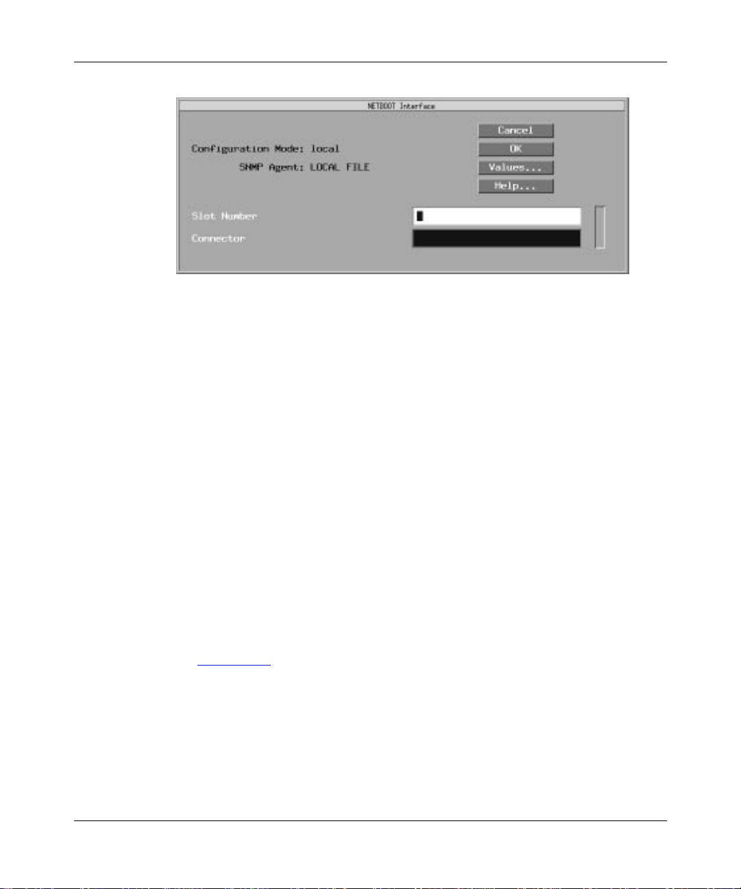
Configuring Remote Access
Figure 4-3. Netboot Interface Window
Specify Slot Number 1 as the physical slot in which the hardware module
3.
is installed.
Be sure that number 1 appears in the Slot Number box. (AN, ANH, and ARN
systems have only one slot.)
4. Enter the name of the connector configured for the Netboot interface.
Enter COM1, COM2, COM3, COM4, or COM5 to configure Netboot over a
synchronous interface.
Enter XCVR1 or XCVR2 to configure Netboot over an Ethernet interface.
Enter TOKEN1 or T OKEN2 to configure Netboot ov er a Token Ring interface
(ARN only).
Note that the interfaces that are available to you depend on the interface
options you purchased with your router.
5. Click on OK.
The Netboot Interfaces window now shows the configured interface
(F
igure 4-4).
4-12 114084 Rev. A
Page 83

Configuring Network Booting
Figure 4-4. Netboot Interfaces Window
Highlight the interface in the scroll box and edit its parameters.
6.
For guidelines, see the parameter descriptions that follow this procedure.
7. Click on Apply.
8. Repeat Steps 2 through 7 to add any additional Netboot interfaces that
you want to configure.
Note: If you configure more than one interface to Netboot, the first interface to
receive a reply from the BOOTP server will use Netboot to reach the router.
9. Click on Done to exit the Netboot Interfaces window.
114084 Rev. A 4-13
Page 84

Configuring Remote Access
Netboot Interface Parameters
Parameter: Connector IP Address
Default: None
Options: Any valid IP address
Function: Specifies the IP address of this interface.
Instructions: Enter the IP address of this interface in dotted decimal notation.
MIB Object ID: 1.3.6.1.4.1.18.3.3.2.10.3.1.4
Parameter: Connector Subnet Mask
Default: None
Options: Any valid IP subnet mask
Function: Specifies the network and subnetwork portion of the 32-bit IP address of
this interface. The Configuration Manager automatically calculates an
appropriate subnet mask, depending on the class of the network to which
the interface connects. However, you can change the subnet mask with
this parameter.
Instructions: Accept the assigned subnet mask, or enter one in dotted decimal notation.
MIB Object ID: 1.3.6.1.4.1.18.3.3.2.10.3.1.5
Parameter: Connector Next Hop
Default: None
Options: Any valid IP address
Function: Specifies the IP address of the next-hop router connected to this interface.
When the router starts up, the next-hop router passes the BOOTP requests
and responses that initiate the transfer of the image and/or configuration
file between the router and the BOOTP server. If the router and BOOTP
server are on the same IP subnet, you do not have to set this parameter.
Instructions: Enter the IP address of the next-hop router connected to the interface you
are adding, in dotted decimal notation.
MIB Object ID: 1.3.6.1.4.1.18.3.3.2.10.3.1.6
4-14 114084 Rev. A
Page 85

Configuring Network Booting
Parameter: Connector Protocol Mask
Default: Point to Point
Options: Point to Point
Annexa
Function: During the boot process, the router will configure the synchronous
interface to the specified protocol.
Instructions: Specify the desired protocol option.
MIB Object ID: 1.3.6.1.4.1.18.3.3.2.10.3.1.7
Parameter: Connector State
Default: Enable
Options: Enable
Function: Enables or disables Netboot on this interface. When set to Enable, any
settings already entered in the other four parameter boxes in the Netboot
Interfaces window appear and are noted by Site Manager so that Netboot
occurs. If the setting is Disable, Site Manager disregards the other
parameters and the router cannot Netboot.
Instructions: If you do not want Site Manager to use the settings on the Netboot
Interfaces window, set this parameter to Disable. If you want Site
Manager to use any of the other four parameters in the Netboot Interfaces
window (r
| Point to Point Internal Clock | Fr Relay Anne xd | Fr Relay
| Fr Relay LMI
| Disable
efer to Figure 4-2), you must set this parameter to Enable.
MIB Object ID: 1.3.6.1.4.1.18.3.3.2.10.3.1.1
114084 Rev. A 4-15
Page 86

Configuring Remote Access
Setting Up Routing Paths for Netboot
You set up the routing paths between the BOOTP server and the routers by
• Enabling each router interface in the paths to the routers
• Creating a BOOTP relay agent forwarding table for each router in the path
• Creating a BOOTP client interface table for the upstream router when the
AN/ANH/ARN is on a Frame Relay PVC in group access mode
Enabling Router Interfaces
You must enable BOOTP relay (also called BOOTP pass-through or gateway) on
all interfaces in the paths between the AN/ANH/ARN routers and the BOOTP
server . For example, you w ould enable BOO TP relay on the interfaces indicated in
igure 4-5.
F
Booting routers
Enable BOOTP on
these interfaces
BOOTP server
Corporate backbone
NPA0007A
Figure 4-5. Enabling BOOTP in a Sample Network
4-16 114084 Rev. A
Page 87

Enable BOOTP relay on an interface as follows:
1. Click on the connector in the Configuration Manager window.
2. Select Edit Circuit in the Edit Connector window.
3. Select Protocols > Add in the Circuit Definition window.
4. Select BOOTP in the Select Protocols window and click on OK.
5. Select File > Exit to exit the Circuit Definition window.
Creating BOOTP Relay Agent Forwarding Tables
You must create a BOOTP relay agent forwarding table for every router passing
BOOTP traffic between the router and the BOOTP server.
The BOOTP relay agent forwarding table allows you to specify the IP interface
that receives the incoming BOO TP request packets, and the associated IP interface
that forwards them. You can add multiple pairs of incoming and outgoing
interfaces to support connections to multiple routers in your network.
Configuring Network Booting
To create the BOOTP relay agent forwarding table, begin at the Configuration
Manager window and complete the following steps.
1. Select Protocols > IP > BOOTP > Relay Agent Interface Table.
The BOOTP Relay Agent Interface Table window appears (F
igure 4-6). This
window lists all IP interfaces on the router.
114084 Rev. A 4-17
Page 88
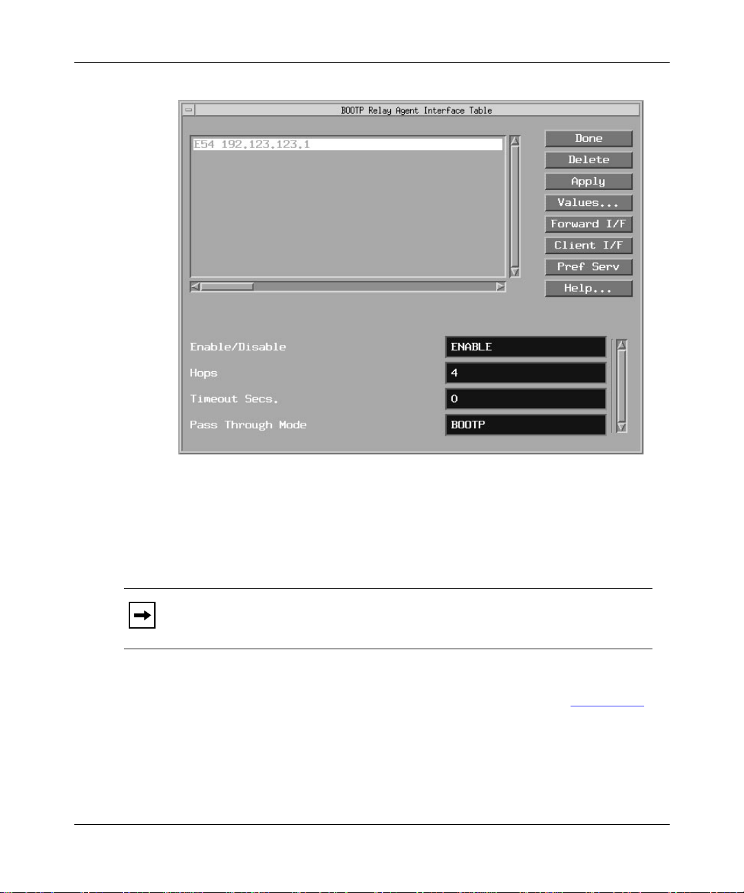
Configuring Remote Access
Figure 4-6. BOOTP Relay Agent Interface Table Window
Click on Help or refer to Configuring SNMP, BOOTP, DHCP, and RARP
Services for a description of the parameters in the BOOTP Relay Agent
Interface Table window.
Note: Be sure that the Timeout Secs. parameter is set to the default, 0.
2. Click on Forward I/F (interface).
The BOOTP Relay Agent Forwarding Table window appears (F
4-18 114084 Rev. A
igure 4-7).
Page 89

Configuring Network Booting
Figure 4-7. BOOTP Relay Agent Forwarding Table Window
Click on Add.
3.
The BOOTP Addresses window appears (F
Figure 4-8. BOOTP Addresses Window
Specify the input IP address and output IP address.
4.
igure 4-8).
For help, refer to the parameter descriptions that follow this procedure.
5. Click on OK.
114084 Rev. A 4-19
Page 90

Configuring Remote Access
The BOOTP Relay Agent Forwarding Table window lists the connector and
input IP address on the left, and the connector and output IP address on the
right.
If you enter an IP address of an interface that is not configured,
instead of the connector (for example,
IP address, Site Manager replaces the
6. Click on Done to exit the window.
BOOTP Relay Agent Interface Parameters
Parameter: Input IP Address
Default: None
Options: Any valid IP address
Function: Specifies the IP interface that receives BOOTP request packets from an
external network. This interface must have BOOTP configured on it.
Instructions: Enter the IP address of the interface through which the router will receive
BOOTP requests.
MIB Object ID: 1.3.6.1.4.1.18.3.5.3.8.3.2.1.3
Parameter: Output IP Address
??? appears
??? 192.32.23.3). If you configure the
??? with the appropriate connector.
Default: None
Options: Any valid IP address
Function: Specifies the IP interface that forwards BOOTP request packets to an
external network.
Instructions: Enter the IP address of the interface through which the router will forward
BOOTP requests.
MIB Object ID: 1.3.6.1.4.1.18.3.5.3.8.3.2.1.4
4-20 114084 Rev. A
Page 91

Creating the BOOTP Client Interface Table
The upstream router is a booting router’s next-hop router. By default, the booting
router’s synchronous interfaces automatically try to get IP addresses from the
upstream router. This is the EZ-Install process.
If the AN/ANH/ARN using EZ-Install gets its address from the upstream router,
and the upstream router’s interface to the AN/ANH/ARN is a Frame Relay group
access PVC, you must use Site Manager to connect to the upstream router and
create a BOOTP client interface table (in addition to a BOOTP relay agent
forwarding table).
Note: You do not need to create a BOOTP client interface table if the Frame
Relay PVC is configured to operate in direct access mode, or if the circuit is
configured to operate with the Bay Networks Standard (HDLC encapsulation)
protocol.
The BOOTP client interface table allows you to specify and pair the IP address of
the AN/ANH/ARN with the DLCI of the Frame Relay group access PVC.
Configuring Network Booting
Note: If you are using EZ-Install over Frame Relay, you can have up to 20
PVCs for a single Frame Relay interface on the upstream router. If you have
more than 20 PVCs on the interface where EZ-Install is occurring, the
EZ Install process may fail. To ensure that the process does not fail, configure
no more than 20 PVCs for a Frame Relay interface.
For more information about the DLCI and Frame Relay, refer to Configuring
Frame Relay Services.
To create the BOOTP client interface table, begin at the BOOTP Relay Agent
Interface Table window (r
1. Click on Client I/F.
The BOOTP Client Interface Table window appears (F
114084 Rev. A 4-21
efer to Figure 4-6) and proceed as follows:
igure 4-9).
Page 92

Configuring Remote Access
Figure 4-9. BOOTP Client Interface Table Window
Click on Add.
2.
The BOOTP Client Interface Address window appears (F
Figure 4-10. BOOTP Client Interface Address Window
Enter the AN/ANH/ARN IP address and its associated DLCI number.
3.
igure 4-10).
For help, refer to the parameter descriptions that follow this procedure.
4. Click on OK.
4-22 114084 Rev. A
Page 93

The BOOTP Client Interface Table window now lists the client IP interface
and the DLCI number you added.
5. Click on Done to exit the window.
BOOTP Client Interface Parameters
Parameter: IP Address
Default: None
Options: Any valid IP address
Function: Specifies the IP address of the AN/ANH/ARN that is using EZ-Install.
This parameter applies only to a Frame Relay group access PVC
connection.
Instructions: Enter the IP address (in dotted decimal notation) of the AN/ANH/ARN
interface.
MIB Object ID: 1.3.6.1.4.1.18.3.5.3.8.1.1.1.3
Configuring Network Booting
Parameter: DLCI Number
Default: None
Range: 16 to 1007
Function: Specifies the identification number of the upstream router’s PVC to the
AN/ANH/ARN. The Frame Relay network uses the DLCI number to
direct data flow from the AN/ANH/ARN to the upstream router.
Instructions: Enter the number in decimal format. Use the DLCI number assigned by
your Frame Relay service provider.
MIB Object ID: 1.3.6.1.4.1.18.3.5.3.8.1.1.1.2
114084 Rev. A 4-23
Page 94

Page 95

Chapter 5
Configuring the Router as a Network Boot Client
To enable an AN, ANH, or ARN for Netboot or Directed Netboot, you configure
one or more router interfaces for network booting. You can do this using a Site
Manager remote connection (as described in Chapter 4) or at the AN/ANH/ARN
console using Technician Interface commands. This chapter describes how to use
the
ifconfig command to configure the AN/ANH/ARN’s initial IP interface to the
•
network
•
bconfig command to specify the location and name of a software image and
configuration file
To Configure This Boot Method Complete These Sections
Netboot or Directed Netboot over a
synchronous interface
Netboot or Directed Netboot over an
Ethernet interface
Netboot or Directed Netboot of an
ARN over a Token Ring interface
114084 Rev. A 5-1
•“Configuring the Router Boot Source”
•“Confi
•“Confi
•“Confi
• “Configuring the Router Boot Source”
• “Configuring a Token Ring Interface for
guring an IP Synchronous Interface for
Network Booting”
guring the Router Boot Source”
guring an Ethernet Interface for
Network Booting”
Network Booting”
Page 96

Configuring Remote Access
Working with a Person at the AN/ANH/ARN Site
Written for a person at the AN/ANH/ARN site, the guides Installing and
Operating BayStack ANH Systems and Installing and Operating BayStack ARN
Routers provide instructions for setting up the router for each of the boot options.
These instructions assume that a network administrator provides the person at the
AN/ANH/ARN site with the appropriate
ifconfig and bconfig commands.
This chapter provides instructions for using the
to configure Netboot and Directed Netboot. If you are not configuring the
AN/ANH/ARN yourself, you can determine the appropriate syntax for these
commands and provide the person at the router site with the exact command lines
to use.
Configuring the Router Boot Source
To use Netboot, you use the bconfig command to specify that the AN/ANH/ARN
configuration file or software image resides on the network. To use Directed
Netboot, you use the
the full pathname to the software image and configuration file.
bconfig Command Format
To configure an interface for Netboot, use the following format for the bconfig
command:
bconfig -d [image | config]
To configure an interface for Directed Netboot, use the following format:
bconfig [image | config] [local | network [
bconfig command to specify the IP address of the server and
ifconfig and bconfig commands
<TFTP host> <TFTP pathname>
]]
You must use the
software image, and again to specify the location of the configuration file.
Refer to T
5-2 114084 Rev. A
able 5-1 for a complete description of the bconfig command.
bconfig command twice: once to specify the location of the
Page 97

Configuring the Router as a Network Boot Client
Table 5-1. bconfig Command Settings
Option Description
image Indicates the router’s software image.
config Indicates the router’s configuration file.
local Indicates that the specified file (image or config) resides in the router’s local file system.
network Indicates that the specified file (image or config) resides on a remote file system.
<TFTP host>
<TFTP
pathname>
-d Reverts to the default values for the software image or configuration file and nullifies any
Specifies the IP address of the TFTP server. If both the software image and configuration
file are on the network, both files must reside on the same host.
Specifies the complete pathname of the remote software image or configuration file.
previously specified IP address and pathname for the file, thus disabling Directed Netboot.
bconfig Command Examples
1. Configure the default Netboot procedure -- use a local image file and look for
the configuration file over the network using BOOTP.
bconfig -d image (or bconfig image local)
bconfig -d config (or bconfig config network)
2. Use Netboot for both the boot image and configuration file.
bconfig image network
bconfig config network
3. Use a local configuration file and Directed Netboot for the boot image file.
bconfig image network 21.3.5.62 /usr/mykernel.exe
bconfig config local
4. Use a local boot image file and Directed Netboot for the configuration file.
bconfig image local
bconfig config network 21.3.5.62 /usr/anstartup/config
5. Use Directed Netboot for both the boot image and configuration file.
bconfig image network 21.3.5.62 /usr/mykernel.exe
bconfig config network 21.3.5.62 /usr/anstartup/config
114084 Rev. A 5-3
Page 98

Configuring Remote Access
Configuring the Netboot Interface
A router interface cannot communicate in an IP network without an IP address.
Because an AN/ANH/ARN netboots over one of its synchronous, Ethernet, or
Token Ring (ARN only) links, the Netboot interface must have a valid IP address.
You have two options for assigning an IP address to an interface:
• Use the Technician Interface
ifconfig command to manually configure a
synchronous, Ethernet, or Token Ring interface for Netboot or Directed
Netboot.
• Configure the upstream router to support automated addressing for EZ-Install.
Chapter 4 describes how to configure the upstream router to support
EZ-Install by creating the BOOTP client interface table. “The Boot Process”
section in Chapter 1 describes how the router automatically obtains an IP
address during the EZ-Install process.
The following sections describe each use of the
ifconfig command.
Configuring an IP Synchronous Interface for Network Booting
Configure a synchronous interface to the IP network using the following interface
configuration command:
ifconfig [
hop address>
The synchronous options variable indicates some combination of the following
settings:
-d | -fr [-annexd | -lmi | -annexa] | -int_clk]
[
synchronous options] <interface> [<IP address> <subnet mask> [<next
]]
Note: Insert a space to separate each command option from the next.
T
able 5-2 describes the ifconfig command arguments for configuring an
AN/ANH/ARN synchronous interface.
5-4 114084 Rev. A
Page 99

Configuring the Router as a Network Boot Client
Table 5-2. ifconfig Command Settings for a Synchronous Interface
Setting Description
Default Setting
-d Resets the router’s IP interface settings to the default values. This
setting tries four W AN configur ations in the f ollowing order until it finds
the correct type for the router’s connection to the network:
1. Bay Networks HDLC encapsulation (also referred to as
Bay Networks Standard Point-to-Point) with external clocking
2. Frame Relay Annex D
3. Frame Relay LMI
4. Frame Relay Annex A
Frame Relay Settings
-fr Configures the router’s synchronous port as a Frame Relay
connection. With this setting, use one of the following options to
specify a DLCMI setting: -annexd, -annexa, or -lmi.
-annexd
-annexa
-lmi
-int_clk Sets the synchronous port to internal clocking at 1.25 MB/s. If you do
<interface>
<IP address>
<subnet mask>
<next hop
address>
When one of these options is used with the -fr setting, it specifies a
DLCMI setting. Use the same setting as the network to which the
router’s Frame Relay interface is connected. The default setting for
Frame Relay is -annexd.
Internal Clocking Setting
not specify this setting, the router defaults to external clocking.
IP Connector Setting
Specifies the IP connector you are configuring. Use the format
com<
port no.
Specifies the IP address of the interface you set with
Provide this address in dotted decimal notation.
Specifies the IP subnet mask of the interface you set with
Provide this address in dotted decimal notation.
Specifies the IP address of the next-hop router. Provide this address
in dotted decimal notation. Specify this address only if there are
intermediate routers between the router and the BOOTP server.
>.
IP Address Settings
<interface>
<interface>
.
.
114084 Rev. A 5-5
Page 100

Configuring Remote Access
Configuring an Ethernet Interface for Network Booting
To configure an AN/ANH/ARN Ethernet interface for network booting, use the
following command format:
ifconfig [-d]
<interface> [<IP address> <subnet mask> [<next hop address>
]]
Table 5-3 describes the ifconfig command arguments for configuring the router’s
Ethernet interface.
Table 5-3. ifconfig Command Settings for an Ethernet Interface
Setting Description
Default Setting
-d Resets the router’s IP interface settings to the default values.
Resetting an Ethernet interface makes it inactive in the network
booting process. (The output of the getcfg command shows the
default as None.)
IP Connector Setting
<interface>
<IP address>
<subnet mask>
<next hop
address>
Specifies the IP connector you are configuring. Use the format
xcvr<
port no.
>.
IP Address Settings
Specifies the IP address of the interface you set with
Provide this address in dotted decimal notation.
Specifies the IP subnet mask of the interface you set with
Provide this address in dotted decimal notation.
Specifies the IP address of the next-hop router. Provide this address
in dotted decimal notation. Specify this address only if there are
intermediate routers between the router and the BOOTP server.
<interface>
<interface>
.
.
Configuring a Token Ring Interface for Network Booting
T o configure an ARN T ok en Ring interface for network booting, use the follo wing
command format:
ifconfig [-d] [ -r<
address>
]]
Table 5-4 describes the ifconfig command arguments for configuring the router’s
Token Ring interface.
5-6 114084 Rev. A
speed
> ]
<interface> [<IP address> <subnet mask> [<next hop
 Loading...