

Page 1
CAUTION: Make sure all units are
switched off whenever connecting
or disconnecting devices.
Scopia XT5000 Server
A
B
C
D
System Installation and Activation
1. Connect all cables to the XT Server Codec Unit (see overleaf).
Connect the Power after all other connections
have been established.
2. Verify the remote control has batteries installed.
3. Verify the LED on the front panel of the Codec Unit is turned on.
4. If the codec unit does not turn on automatically, press the
button on the remote control.
Product Registration
1. Open the envelope that came with the XT Server.
2. Locate the serial number and product key.
3. On a computer, open a browser and navigate to
http://licensing.radvision.com.
4. Complete the online registration form and enter the serial number
and product key. The web registration form returns a license key.
5. Write down the license key and enter it when required
by the system.
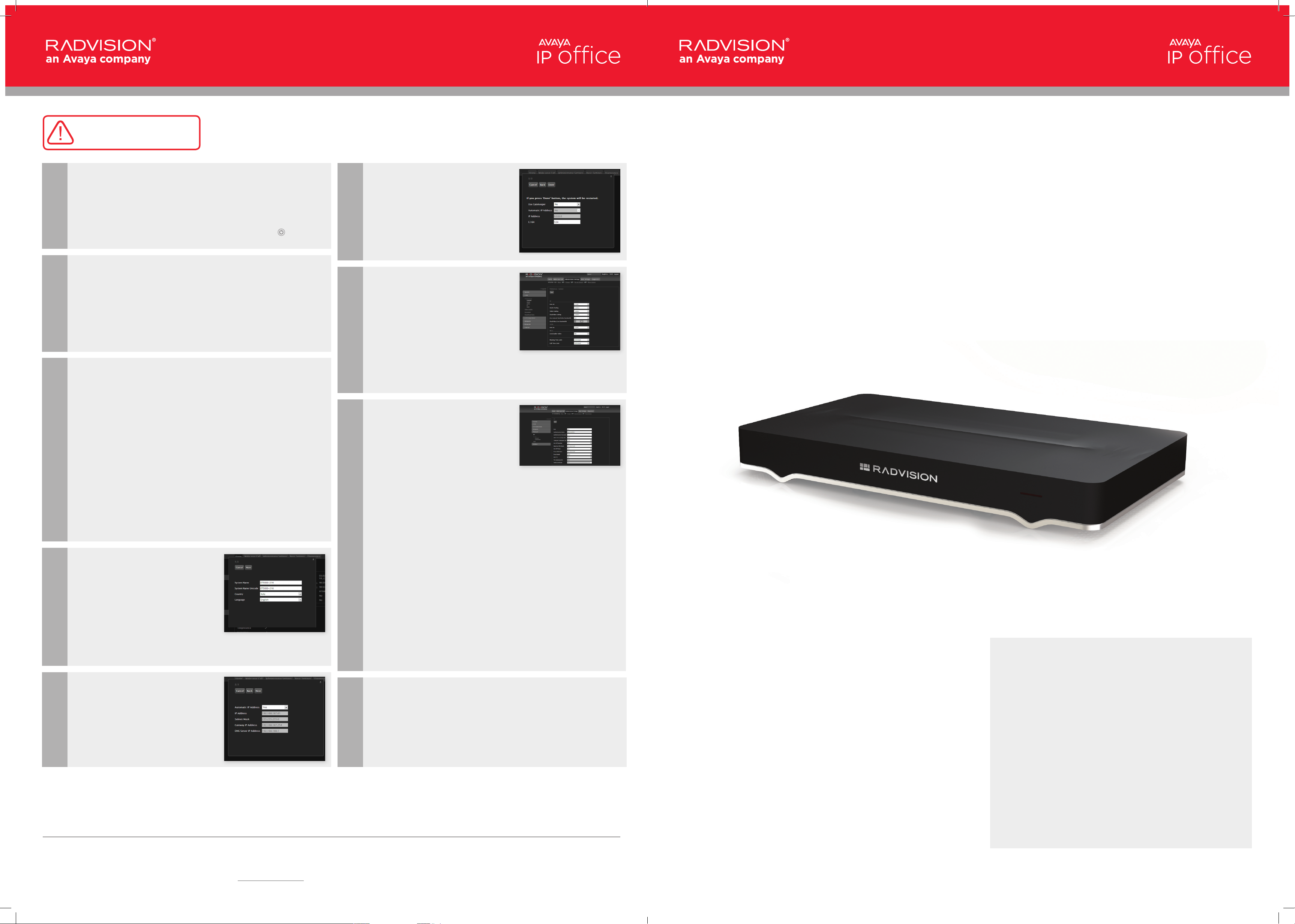
System configuration
If the HD output is connected to a display, you can configure the
system using the local User Interface or configure remotely via the
web interface. If the XT Server is not connected to a display,
you must first identify its IP address:
1. Navigate to the IP Office documentation link in
the Customer Letter.
2. Download the “Installation Notes for Discovering the IP
Address for the XT Server”
3. Follow the instructions in this document to identify the IP address
using one of the following methods:
• Bonjour discovery
• SNMP discovery
• Serial port query
4. Once the IP has been identified you can access the system using
the web interface. The default username is Admin with
the password 1234.
5. Once logged in for the first time, the system initiates a quick
configuration wizard as described in the following steps.
Country and Language
of the System
1. The System Name field displays the
name of this Codec Unit as displayed
in a videoconference, for example:
• Hong Kong, or
• 9th Floor Conf Rm
2. Select the Country and
preferred Language.
3. Then select Next.
F
G
H
Gatekeeper Settings
1. In the Use Gatekeeper field,
select No.
2. Then select Done.
3. The system will restart.
Local Audio / Video
settings
1. Typically the XT Server has no
direct camera or microphone
connections. In this case, disable local
audio and video connections:
2. Browse the web page
Administrator Settings > Calls >
Preferences > General
3. Set the parameter
Local audio video to No
4. Select Save.
Register the XT with
IP Office
1. Browse the web page Administrator
Settings > Protocols > SIP
2. Change the SIP settings as follows:
a. User: Set this to match the extension
number of the IP Office user
configured on the IP Office system.
b. Authentication Name: Set this to
match the Name set on the
IP Office user.
c. Authentication Password: Set this to
match the Login Code set on the
IP Office user.
d. Listening Port: Set this to match
the IP Office system setting.
The default is 5060.
e. Transport Outbound Call:
Set this to UDP.
f. Use SIP Registrar: Set this to Yes.
g. Registrar DNS Name: Set this to the IP
Office system’s IP address or FQDN.
h. Use SIP Proxy: Set this to Yes.
i. Proxy DNS Name: Set this to the IP
Office system’s IP address or FQDN.
j. Proxy Model: Leave this set to Auto.
k. Use TLS: leave this set to No
3. Select Save.
for IP Office
Quick Setup Guide
The Avaya Video Collaboration Solution for IP Office is designed specifically
for small and midsize enterprise customers who want to take advantage
of the benefits desktop, mobile and room-based video collaboration can
provide to their business. The solution integrates Avaya IP Office with Scopia
videoconferencing technology to help customers drive greater productivity,
improve customer service, and control costs.
Package Content:
E
© 2013 Radvision Ltd. All intellectual property rights in this publication are owned by Radvision Ltd. and are protected by United States copyright laws, other applicable copyright laws and international treaty provisions. Radvision
Ltd. retains all right s not expressly granted.
This pu blication is Radvision co nfidential. No part of this pu blication may be rep roduced in a ny form w hatsoever or used to m ake any derivative work withou t prior written app roval by Ra dvision Ltd. No representation of warranties
for fitne ss for any purpose oth er than wh at is specifica lly mentioned in this guide is made either by Radvi sion Ltd. or its agents. Rad vision Ltd. reser ves the rig ht to revise this public ation an d make changes with out obligatio n to notify
any perso n of such revisio ns or changes. Radvisio n Ltd. may make improvements or chang es in the product(s) and/or the program(s) described in this documentation at any time. If there is any sof tware on removabl e media described
in this publication, it is furnished under a license agreement included with the product as a separate document. If you are unable to locate a copy, please contact Radvision Ltd. and a copy will be provided to you. Unless otherwise
indic ated, Radvision registered trademarks are registered in the United States and other te rritories. All registere d trademarks reco gnized . All right reserve d.
For further information contact Radvision or your local distributor or rese ller. http://www.radvision.com
Network Settings
1. Update your network settings as
needed. Please note we strongly
recommend using a static IP.
2. If you prefer to keep using
Automatic IP Address then
select Next.
I
NOTE: Please refer to the Customer Letter and the “IP Office video installation notes”
document for details about IP Office configuration.
Install XT Desktop server
1. Download the Scopia XT Desktop Server software from the link
provided in the Customer Letter.
2. Download the Deployment Guide for Scopia XT Desktop Server
from the link provided in the customer letter and follow
the instructions.
3. Install the XT Desktop Server on a dedicated PC server
(Windows Server 2008/2012).
• Scopia XT5000 Codec Unit
• Scopia XT Remote C o n t r o l U n i t
• DVI-I to VGA converter
• Cable LAN 4mt
• Cable HDMI M/M, 2.5M
• Power Supply and power cable
• Remote Control Batteries
• Codec Unit Camera Cable for Control
and Power Supply
PN 61111-00074 rev A01
Page 2
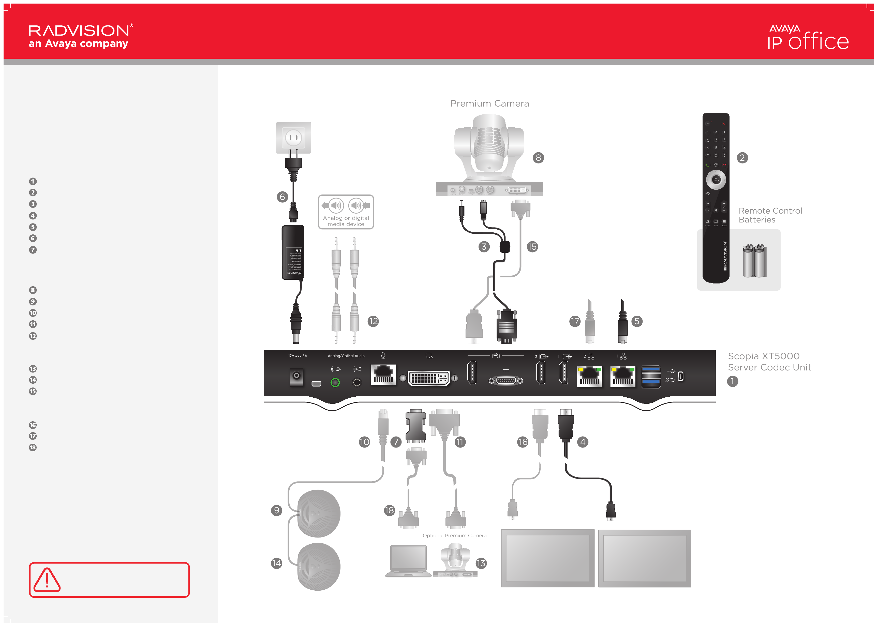
Premium Camera
2
17
16
5
8
Analog or digital
media device
Remote Control
Batteries
DC IN 12V IN RS-232C OUT DVI
IR SELECT
1 2 3
1
2
3
4
5
6
7
8
9
SYSTEM
SELECT
6
1
4
7
14
9
Scopia XT5000
Server Codec Unit
12
18
10
11
DC IN 12V IN RS-232C OUT DVI
IR SELECT
1 2 3
1
2
3
4
5
6
7
8
9
SYSTEM
SELECT
13
Optional Premium Camera
CAUTION: the mains
cable is used as a
disconnecting device,
use therefore an easily
accessible outlet
located near the
device for the power
supply connection.
Never remove the
mains plug while the
device is connected.
3 15
Scopia XT5000 Server
for IP Office
Quick Hardware Setup
Package Content:
Codec Unit
Remote Control Unit and batteries
Codec Unit Camera Cable for Control and Power Supply
HDMI Cable for Display
Ethernet Cable
Power Supply and Power cable
DVI-I to VGA converter for PCs with VGA output
Radvision Optional Accessories –
Not Included
Scopia XT Premium Camera
3-way Microphone POD
3-way microphone POD cable
DVI to DVI Cable
Audio Cable. Both sockets on the unit are dual purpose.
They accept either an analog 3.5mm MiniJack cable or
an optical Toslink cable with a Toslink mini-plug adapter.
Optical digital audio format is S/PDIF
Optional Premium Camera to be connected to DVI input
Optional 2nd 3-way microphone POD
HDMI to DVI cable for camera
Non Radvision
HDMI Cable for Mon2
Ethernet Cable for LAN
VGA cable
CAUTION: Make sure all units are
switched off whenever connecting
or disconnecting devices.
 Loading...