

Avaya Nortel Communication Server 1000 User Manual

Nortel Communication Server 1000
IP Line Fundamentals
NN43100-500
.

Document status: Standard
Document version: 02.02
Document date: 4 February 2008
Copyright © 2003–2008, Nortel Networks
All Rights Reserved.
Sourced in Canada
LEGAL NOTICE
While the information in this document is believed to be accurate and reliable, except as otherwise expressly agreed
to in writing NORTEL PROVIDES THIS DOCUMENT "AS IS" WITHOUT WARRANTY OR CONDITION OF ANY
KIND, EITHER EXPRESS OR IMPLIED. The information and/or products described in this document are subject
to change without notice.
Nortel, Nortel (Logo), the Globemark, SL-1, Meridian 1, and Succession are trademarks of Nortel Networks.
All other trademarks are the property of their respective owners.

Contents
New in this release 13
Features 13
Other 13
Subject 14
How to get help 17
Getting help from the Nortel Web site 17
Getting help over the telephone from a Nortel Solutions Center 17
Getting help from a specialist by using an Express Routing Code 17
Getting help through a Nortel distributor or reseller 18
Description 19
Contents 19
Introduction 19
Interworking 21
Applicable systems 21
System requirements 22
System configurations 22
Software delivery 24
Required packages 25
Fax/Modem pass through 25
Voice Gateway Media Cards 27
Virtual superloops, Virtual TNs, and physical TNs 44
Licenses 44
Zones 46
Administration 46
3
Revision history 13
Structure 15
Digital Signaling Processor daughterboards 20
Modem traffic 26
Media Card 32S 36
Reliable User Datagram Protocol 42
Secure Real-time Transport Protocol 43
Features 49
Contents 49
Copyright © 2003–2008, Nortel Networks
.
Nortel Communication Server 1000
IP Line Fundamentals
NN43100-500 02.02 Standard
Release 5.5 4 February 2008

4 Contents
Introduction 50
Live Dialpad 52
Diagnostics 53
Unicode support 53
Pop-up and USB keyboard support 54
IP Client cookies 54
e2dsetShow () 55
New IP Phone Types 55
Unique TN Types for existing IP Phones 56
Automatic IP Phone TN conversion (Flexible Registration) 57
Manual IP Phone TN conversion 58
Active Call Failover for IP Phones 58
DSP peg counter for CS 1000E systems 81
Enhanced UNIStim Firmware Download for IP Phones 81
Firmware download using UNIStim FTP 110
NAT Traversal feature 117
Corporate Directory 134
Personal Directory, Callers List, and Redial List 135
IP Call Recording 135
pbxLink connection failure detection 144
LD 117 STAT SERV 146
IP Phone support 149
IP Phone 2001 151
IP Phone 2002 151
IP Phone 2004 152
IP Phone 1210 154
IP Phone 1220 155
IP Phone 1230 156
IP Phone 1200 Series Key Expansion Module 157
IP Phone 2007 158
IP Audio Conference Phone 2033 159
IP Softphone 2050 160
Expansion Module for IP Softphone 2050 160
WLAN Handsets 2210/2211/2212 161
WLAN Handsets 6120/6140 162
IP Phone 1110 162
IP Phone 1120E 163
IP Phone 1140E 164
IP Phone 1150E 165
Expansion Module for IP Phone 1100 Series 166
Element Manager support 167
Call Statistics collection 168
Programmable line/DN feature keys (self-labeled) 177
Copyright © 2003–2008, Nortel Networks
.
Nortel Communication Server 1000
IP Line Fundamentals
NN43100-500 02.02 Standard
Release 5.5 4 February 2008

Contents 5
Private Zone configuration 178
Run-time configuration changes 181
Network wide Virtual Office 182
Bandwidth Management for Network wide Virtual Office 185
Requirements 186
Branch Office and Media Gateway 1000B 186
802.1Q support 187
Data Path Capture tool 190
IP Phone firmware 191
Graceful Disable 191
Hardware watchdog timer 192
Codecs 193
Set type checking and blocking 194
Enhanced Redundancy for IP Line nodes 195
Personal Directory, Callers List, and Redial List 199
Contents 199
Introduction 199
Personal Directory 201
Callers List 202
Redial List 204
IP Phone Application Server configuration and administration 205
IP Phone Application Server database maintenance 208
Call Server configuration 212
Password administration 213
Codecs 215
Contents 215
Introduction 215
Codec configuration 217
Codec registration 219
Codec negotiation 222
Codec selection 224
Installation and configuration summary 229
Contents 229
Introduction 229
Before you begin 229
Installation summary 229
Voice Gateway Media Card installation summary sheet 232
Installation and initial configuration of an IP Telephony node 235
Contents 235
Introduction 235
Equipment considerations 236
Install the hardware components 236
Copyright © 2003–2008, Nortel Networks
.
Nortel Communication Server 1000
IP Line Fundamentals
NN43100-500 02.02 Standard
Release 5.5 4 February 2008

6 Contents
Initial configuration of MC 32S card 251
Configuring the Leader and Follower on the MC 32S 251
Initial configuration of IP Line data 251
Configure the Expansion Module for IP Phone 1100 Series 265
Configure the IP Phone 1200 Series Key Expansion Module 267
Node election rules 271
Configuration of IP Telephony nodes using Element Manager273
Contents 273
Introduction 273
Configure IP Line data using Element Manager 274
Change the login banner 279
Transfer node configuration from Element Manager to the Voice Gateway Media
Cards 301
Upgrade the Voice Gateway Media Card software and IP Phone firmware 307
Download the current loadware and IP Phone firmware 309
Assemble and install an IP Phone 319
Change the default IPL CLI Shell password 319
Configure the IP Phone Installer Passwords 319
Import node configuration from an existing node 320
IP Line administration 323
Contents 323
Introduction 323
IP Line feature administration 324
Password security 328
IP configuration commands 344
TLAN network interface configuration commands 345
Display the number of DSPs 346
Display IP Telephony node properties 346
Packet loss monitor 349
Transfer files using the CLI 350
Download the IP Line error log 352
Reset the Operational Measurements file 352
IP Line administration using Element Manager 353
Contents 353
Introduction 353
Element Manager administration procedures 353
View Traffic reports 363
Backup and restore data 387
Update IP Telephony node properties 390
Update other node properties 409
Telnet to a Voice Gateway Media Card using Virtual Terminal 409
Check the Voice Gateway Channels 411
Setting the IP Phone Installer Password 412
Copyright © 2003–2008, Nortel Networks
.
Nortel Communication Server 1000
IP Line Fundamentals
NN43100-500 02.02 Standard
Release 5.5 4 February 2008

Contents 7
IP Line administration using TM 3.1 417
Contents 417
Introduction 417
TM administration procedures 417
Back up and restore TM data 432
Add an IP Telephony node in TM by retrieving an existing node 432
IP Line CLI access using Telnet or local RS-232 maintenance port 435
Voice Gateway Media Card maintenance 437
Contents 437
Introduction 437
Faceplate maintenance display codes 437
System error messages 441
IP Line and IP Phone maintenance and diagnostics 446
IP Line CLI commands 455
Lamp Audit and Keep Alive functions 483
Voice Gateway Media Card self-tests 487
Troubleshoot a software load failure 487
Troubleshoot an IP Phone installation 490
Maintenance telephone 491
Replace the Media Card CompactFlash 491
Voice Gateway Media Card maintenance using Element
Manager 493
Contents 493
Introduction 493
Replace a Voice Gateway Media Card 493
Add another Voice Gateway Media Card 499
Access CLI commands from Element Manager 501
Access the CLI from Element Manager 513
Convert IP Trunk Cards to Voice Gateway Media Cards 515
Contents 515
Introduction 515
Before you begin 516
Convert the IP Trunk cards 516
Add the converted cards to an IP Telephony node 517
Appendix A NAT router requirements for NAT Traversal
feature 525
Contents 525
Description 525
Requirements 526
Natcheck output 528
Copyright © 2003–2008, Nortel Networks
.
Nortel Communication Server 1000
IP Line Fundamentals
NN43100-500 02.02 Standard
Release 5.5 4 February 2008

8 Contents
Appendix B I/O, maintenance, and extender cable description531
Contents 531
Introduction 531
NTMF94EA I/O cable 531
Connector pin assignments 532
NTAG81CA maintenance cable description 535
NTAG81BA maintenance extender cable 536
Replace the NT8D81BA cable with the NT8D1AA cable and install the NTCW84JW
special IPE filter 537
Appendix C Product integrity 541
Contents 541
Introduction 541
Reliability 541
Environmental specifications 542
Appendix D Subnet Mask Conversion from CIDR to Dotted
Decimal Format 545
Introduction 545
Appendix E Download IP Line files from Nortel Web site 547
Contents 547
Introduction 547
Download files from Nortel Web site 547
Appendix F Moving Voice Gateway Media Cards between
systems 549
Contents 549
Introduction 549
Reconfiguring the Voice Gateway Media Card 549
Node has Leader configured 550
Node has no Leader configured 555
Upgrading the software 562
Index 565
Procedures
Procedure 1 Accessing Ethernet Diagnostics in Element Manager 100
Procedure 2 Accessing the uftpTurboMode command 105
Procedure 3 Accessing the uftpTurboModeShow command 106
Procedure 4 Accessing uftpTurboModeTimeoutSet command 107
Procedure 5 Accessing uftpAutoUpgradeTimeoutSet command 108
Procedure 6 Accessing the call log options 203
Procedure 7 Configuring the IP Phone Application Server on a separate
Signaling Server 207
Procedure 8 Backing up the IP Phone Application Server database server
manually 209
Procedure 9 Performing a full database recovery 210
Procedure 10 Performing a selective database recovery 211
Copyright © 2003–2008, Nortel Networks
.
Nortel Communication Server 1000
IP Line Fundamentals
NN43100-500 02.02 Standard
Release 5.5 4 February 2008

Contents 9
Procedure 11 Preinstallation and configuration steps 230
Procedure 12 Installing the ITG-P 24-port line card 239
Procedure 13 Installing the CompactFlash card on the Media Card 241
Procedure 14 Installing the Media Card 242
Procedure 15 Replacing the existing I/O Panel Filter Connector 244
Procedure 16 Installing the NTMF94EA ELAN, TLAN, serial interface
cable 248
Procedure 17 Installing the Shielded 50-pin to Serial/ELAN/TLAN Adapter
onto the Media Card 250
Procedure 18 Configuring the ELAN network interface IP address for the
active ELNK 252
Procedure 19 Viewing Element Manager for Zone Configuration 255
Procedure 20 Using Element Manager to configure Voice Gateway
channels 257
Procedure 21 Configuring a virtual Superloop in Element Manager 260
Procedure 22 Turning off browser caching in Internet Explorer 275
Procedure 23 Launching Element Manager 277
Procedure Changing the Element Manger logon banner 279
Procedure 24 Adding an IP Telephony node manually 280
Procedure 25 Configuring SNMP trap destinations 284
Procedure 26 Configuring DSP Profile data 285
Procedure 27 Configuring QoS 289
Procedure 28 Configuring the Call Server ELAN network interface IP address
(Active ELNK), TLAN voice port, and routes 291
Procedure 29 Configuring access to the file server 295
Procedure 30 Setting the loss plan for the UK 297
Procedure 31 Adding a card and configuring Voice Gateway Media Card
properties 298
Procedure 32 Submitting and transferring the node information 300
Procedure 33 Configuring the Leader IP address for a second or subsequent
node 302
Procedure 34 Transmitting node properties to Leader 304
Procedure 35 Configuring the Follower cards 306
Procedure 36 Uploading loadware and firmware files 310
Procedure 37 Upgrading the card loadware 311
Procedure 38 Rebooting the Voice Gateway Media Card 312
Procedure 39 Re-enabling the Voice Gateway Media Card 313
Procedure 40 Upgrading the IP Phone firmware 314
Procedure 41 Importing node files 320
Procedure 42 Configuring the Administrative IP Phone Installer
Password 339
Procedure 43 Configuring the temporary IP Phone Installer Password 342
Procedure 44 Resetting the user name and password to default 343
Procedure 45 Retrieving the current OM file from the Voice Gateway Media
Card using Element Manager 354
Procedure 46 Viewing IP Line log files 386
Procedure 47 Backing up the Call Server data 388
Procedure 48 Restoring the Call Server data 390
Procedure 49 Updating the IP Telephony node properties 391
Procedure 50 Adding a Voice Gateway Media Card to the node 392
Copyright © 2003–2008, Nortel Networks
.
Nortel Communication Server 1000
IP Line Fundamentals
NN43100-500 02.02 Standard
Release 5.5 4 February 2008

10 Contents
Procedure 51 Deleting a follower Voice Gateway Media Card from the
node 397
Procedure 52 Deleting the Leader Voice Gateway Media Card 399
Procedure 53 Changing the IP addresses of an IP Telephony node in Element
Manager 400
Procedure 54 Restarting a Voice Gateway Media Card at the CLI 407
Procedure 55 Restarting a Voice Gateway Media Card in Element
Manager 408
Procedure 56 Changing the IP address of the Leader card 409
Procedure 57 Accessing a Voice Gateway Media Card using Telnet 410
Procedure 58 Checking the Voice Gateway Channels 412
Procedure 59 Setting the administrative and temporary IP Phone Installer
Passwords 412
Procedure 60 Scheduling Reports 419
Procedure 61 Generating reports 421
Procedure 62 Opening an Operational Measurement (OM) report 422
Procedure 63 Retrieving the current OM file from the Voice Gateway Media
Card using TM 423
Procedure 64 Viewing IP Line info and error log 432
Procedure 65 Adding a node by retrieving an existing node 433
Procedure 66 Accessing a Voice Gateway Media Card using Telnet 436
Procedure 67 Troubleshooting an IP Phone installation 490
Procedure 68 Removing the CompactFlash 491
Procedure 69 Replacing a Follower Voice Gateway Media Card 494
Procedure 70 Replacing a Leader Voice Gateway Media Card 496
Procedure 71 Add another Voice Gateway Media Card to the system 499
Procedure Accessing CLI commands for the Media Card 32S 506
Procedure 72 Converting IP Trunk card to Voice Gateway Media Cards 516
Procedure 73 Adding the converted Voice Gateway Media Cards into an
existing IP Telephony node 518
Procedure 74 Importing all converted Voice Gateway Media Cards into a new
IP Telephony node 520
Procedure 75 Preventing ground loops 534
Procedure 76 Removing an NT8D81BA cable 539
Procedure 77 Installing an NTCW84JA filter and NT8D81AA cable 539
Procedure 78 Converting a subnet mask from CIDR format to dotted decimal
format 545
Procedure 79 Reconfiguring a Voice Gateway Media Card running CS 1000
Release 4.5 or later (Follower on original system) 552
Procedure 80 Reconfiguring a Voice Gateway Media Card running CS 1000
Release 4.5 or later (Leader in original system) 553
Procedure 81 Reconfiguring a Voice Gateway Media Card running CS 1000
Release 4.0 or earlier (Leader or Follower) 554
Procedure 82 Reconfiguring the ITG-P 24-port card running CS 1000
Release 4.5 or later (Leader or Follower) 556
Procedure 83 Reconfiguring an ITG-P 24-port card running CS 1000 Release
4.0 (Leader or Follower) 557
Procedure 84 Reconfiguring the Media Cards running CS 1000 Release 4.5
or later (Leader or Follower) 559
Copyright © 2003–2008, Nortel Networks
.
Nortel Communication Server 1000
IP Line Fundamentals
NN43100-500 02.02 Standard
Release 5.5 4 February 2008

Contents 11
Procedure 85 Reconfiguring the Media Cards running CS 1000 Release 4.0
or earlier (Leader or Follower) 560
Procedure 86 Upgrading the software for the ITG-P 24-port card or the Media
Card running CS 1000 Release 4.0 or earlier 562
Copyright © 2003–2008, Nortel Networks
.
Nortel Communication Server 1000
IP Line Fundamentals
NN43100-500 02.02 Standard
Release 5.5 4 February 2008

12 Contents
Copyright © 2003–2008, Nortel Networks
.
Nortel Communication Server 1000
IP Line Fundamentals
NN43100-500 02.02 Standard
Release 5.5 4 February 2008

New in this release
The following sections detail what is new in IP Line Fundamentals
(NN43100-500) for CS 1000 Release 5.5.
•
Features
•
Other
Features
CS 1000 Release 5.5 introduces support for IP Phone 1210, IP Phone
1220, IP Phone 1230, and IP Phone 1200 Series Key Expansion Module.
Other
IP Line Fundamentals for CS 1000 Release 5.5 includes the following
additional changes:
•
additional CLI commands for Element Manager
•
additional traffic reports in Element Manager (system and customer)
13
• updated Web link for downloading content
Revision history
February 2008
December 2007
November 2007
Copyright © 2003–2008, Nortel Networks
.
Standard 02.02. This document is up-issued to support
Communication Server 1000 Release 5.5. This document
contains an update to technical content.
Standard 02.01. This document is up-issued to support
Communication Server 1000 Release 5.5.
Standard 01.03. This document is up-issued to support
Communication Server 1000 Release 5.0. This document
is reflects updated technical content: removal of G729AB
codec support for the IP Audio Conference Phone 2033,
corrected command e2dsetshow, and added a statement to
IP Peer calls section.
Nortel Communication Server 1000
IP Line Fundamentals
NN43100-500 02.02 Standard
Release 5.5 4 February 2008

14 New in this release
June 2007
May 2007
December 2006
July 2006 Standard 9.00. This document is up-issued to support CS
May 2006
April 2006
January 2006
August 2005 Standard 5.00. This document is up-issued following the
Standard 01.02. This document is up-issued to support
Communication Server 1000 Release 5.0. This document
includes an update to the IP Phone firmware upgrade
procedures.
Standard 01.01. This document is issued to support
Communication Server 1000 Release 5.0. This document is
renamed IP Line Fundamentals (NN43100-500) and contains
information previously contained in the following legacy
document, now retired: (553-3001-365).
Standard 10.00. This document is up-issued to support CS
1000 Release 4.5.
1000 Release 4.5.
Standard 8.00. This document is up-issued to reflect changes
to the IPL> CLI default user name and password.
Standard 7.00. This document is up-issued to reflect changes
in technical content.
Standard 6.00. This document is up-issued to reflect changes
in technical content.
removal of regulatory data.
August 2005
September 2004
May 2004
October 2003
Subject
Standard 4.00. This document is up-issued to support Nortel
Communication Server 1000 Release 4.5.
Standard 3.00. This document is up-issued to support Nortel
Networks Communication Server 1000 Release 4.0.
Standard 2.00. This document is up-issued to support the
Nortel Networks Mobile Voice Client 2050 (MVC 2050).
Standard 1.00. This document is a new NTP for Succession
3.0. It was created to support a restructuring of the
Documentation Library. This document contains information
previously contained in the following legacy document, now
retired:
(553-3001-204).
IP Line: Description, Installation and Operation
This document:
•
describes the physical and functional characteristics of the IP Line
application for Nortel Communication Server (CS) 1000 Release 5.5
system and describes its use on Signaling Servers and Voice Gateway
Media Cards.
•
explains how to engineer, install, configure, administer, and maintain an
IP Telephony node that contains Voice Gateway Media Cards.
Copyright © 2003–2008, Nortel Networks
.
Nortel Communication Server 1000
IP Line Fundamentals
NN43100-500 02.02 Standard
Release 5.5 4 February 2008

Structure
This document has separate chapters that are applicable only to either
Telephony Manager (TM) 3.1 or Element Manager.
The configuration, administration, and maintenance sections are divided
into two chapters. For example, a generic configuration chapter deals
with tasks related to the installation and configuration of IP Line. This
chapter is followed by the configuration chapter for Element Manager. The
administration and maintenance chapters have the same format.
Note on legacy products and releases
This NTP contains information about systems, components, and features
that are compatible with Nortel Communication Server 1000 Release 5.5
software. For more information about legacy products and releases, click
the Technical Documentation link under Support & Training on the Nortel
home page: w
Related information
The following documents are referenced in this document:
•
Subject 15
ww.nortel.com
Converging the Data Network with VoIP Fundamentals (NN43001-260)
• Transmission Parameters Reference (NN43001-282)
•
Signaling Server Installation and Commissioning (NN43001-312)
•
Branch Office Installation and Commissioning (NN43001-314)
•
Telephony Manager 3.1 System Administration (NN43050-601)
•
WLAN IP Telephony Installation and Commissioning (NN43001-504)
•
Emergency Services Access Fundamentals (NN43001-613)
•
Element Manager System Reference—Administration (NN43001-632)
•
Enterprise Common Manager Fundamentals (NN43001-116).
•
IP Phones Fundamentals (NN43001-368)
•
Software Input Output Reference—System Messages (NN43001-712)
•
Communication Server 1000M and Meridian 1 Small System Planning
and Engineering (NN43011-220)
•
Communication Server 1000M and Meridian 1 Large System Planning
and Engineering (NN43021-220)
•
Communication Server 1000M and Meridian 1 Large System
Maintenance (NN43021-700)
•
CommunicationServer 1000E Planningand Engineering (NN43041-220)
•
IP Phone 2001 User Guide (NN43115-102)
•
IP Phone 2002 User Guide (NN43116-104)
Copyright © 2003–2008, Nortel Networks
.
Nortel Communication Server 1000
IP Line Fundamentals
NN43100-500 02.02 Standard
Release 5.5 4 February 2008

16 New in this release
•
•
•
•
•
•
•
•
•
•
•
•
•
•
IP Phone 2004 User Guide (NN43117-102)
IP Phone 2007 User Guide (NN43118-100)
IP Audio Conference Phone 2033 User Guide (NN43111-100)
IP Softphone 2050 User Guide (NN43119-101)
Mobile Voice Client 2050 User Guide (NN43119-103)
IP Phone 1110 User Guide (NN43110-101)
IP Phone 1120E User Guide (NN43112-103)
IP Phone 1140E User Guide (NN43113-106)
IP Phone 1150E User Guide (NN43114-100)
IP Phone Key Expansion Module User Guide (NN43119-102)
Expansion Module for IP Phone 1100 Series User Guide (NN43130-101)
IP Phone 1210 User Guide (NN43140-101)
IP Phone 1220 User Guide (NN43141-101)
IP Phone 1230 User Guide (NN43142-101)
• IP Phone 1200 Series Key Expansion Module User Guide
Copyright © 2003–2008, Nortel Networks
.
Nortel Communication Server 1000
IP Line Fundamentals
NN43100-500 02.02 Standard
Release 5.5 4 February 2008

How to get help
This chapter explains how to get help for Nortel products and services.
Getting help from the Nortel Web site
The best way to get technical support for Nortel products is from the Nortel
Technical Support Web site:
ww.nortel.com
w
This site provides quick access to software, documentation, bulletins, and
tools to address issues with Nortel products. From this site, you can:
•
download software, documentation, and product bulletins
•
search the Technical Support Web site and the Nortel Knowledge Base
for answers to technical issues
•
sign up for automatic notification of new software and documentation
for Nortel equipment
•
open and manage technical support cases
17
Getting help over the telephone from a Nortel Solutions Center
If you do not find the information you require on the Nortel Technical Support
Web site, and you have a Nortel support contract, you can also get help
over the telephone from a Nortel Solutions Center.
In North America, call 1-800-4NORTEL (1-800-466-7835).
Outside North America, go to the following Web site to obtain the telephone
number for your region:
w
ww.nortel.com/callus
Getting help from a specialist by using an Express Routing Code
To access some Nortel Technical Solutions Centers, you can use an Express
Routing Code (ERC) to quickly route your call to a specialist in your Nortel
product or service. To locate the ERC for your product or service, go to:
Nortel Communication Server 1000
IP Line Fundamentals
NN43100-500 02.02 Standard
Copyright © 2003–2008, Nortel Networks
.
Release 5.5 4 February 2008

18 How to get help
www.nortel.com/erc
Getting help through a Nortel distributor or reseller
If you purchased a service contract for your Nortel product from a distributor
or authorized reseller, contact the technical support staff for that distributor
or reseller.
Copyright © 2003–2008, Nortel Networks
.
Nortel Communication Server 1000
IP Line Fundamentals
NN43100-500 02.02 Standard
Release 5.5 4 February 2008

Description
Contents
This section contains the following topics:
•
"Introduction" (page 19)
•
"Interworking" (page 21)
•
"Applicable systems" (page 21)
•
"System requirements" (page 22)
•
"System configurations" (page 22)
•
"Software delivery" (page 24)
•
"Required packages" (page 25)
•
"Voice Gateway Media Cards" (page 27)
•
"Virtual superloops, Virtual TNs, and physical TNs" (page 44)
•
"Licenses" (page 44)
19
•
"Zones" (page 46)
•
"Administration" (page 46)
Introduction
Communication Server (CS) 1000 Release 5.5 requires the IP Line
application.
The IP Line application provides an interface that connects IP Phones to a
CS 1000 Call Server.
CS 1000 Release 5.5 requires a Signaling Server to operate. You must
upgrade your Meridian 1 system, if your system is IP enabled to include a
Signaling Server, which in turn becomes a CS 1000M system. CS 1000
Release 5.5 is supported on an analog/digital (TDM) only system without
a Signaling Server if the system is not IP enabled. For information about
upgrading your system, see Communication Server 1000M and Meridian 1
Copyright © 2003–2008, Nortel Networks
.
Nortel Communication Server 1000
IP Line Fundamentals
NN43100-500 02.02 Standard
Release 5.5 4 February 2008

20 Description
Digital Signaling Processor daughterboards
Small System Planning and Engineering (NN43011-220) or Communication
Server 1000M and Meridian 1 Large System Planning and Engineering
(NN43021-220).
ATTENTION
The IP Line version of software must match the Call Server version.
Digital Signaling Processor (DSP) daughterboards on the Media Gateway
Controller (MGC) provide DSP resources for connecting IP and Time
Divisional Multiplexing (TDM) devices together in a CS 1000E Media
Gateway (MG 1000E) system. The following DSP daughterboards are
available:
• 32 port daughterboard
•
96 port daughterboard
These daughterboards provide an optional solution to installing the
Voice Gateway Media Cards within the CS 1000E Media Gateway (MG
1000E) chassis. However, Voice Gateway Media Cards are still supported
within an MG 1000E with a Media Gateway Controller (MGC) and DSP
daughterboards. The MGC is only used in a Media Gateway chassis or an
Option 11C cabinet.
For further information about DSP resources residing on the MGC that are
configured with DSP daughterboards, see Communication Server 1000E
Installation and Commissioning (NN43041-310).
Voice Gateway Media Cards
If a Media Card 32-port card, a Media Card 32S, or an ITG-P 24-port card is
running IP Line software, it is known as a Voice Gateway Media Card.
In this document, Media Card 32-port card and Media Card 32S card are
referred to as Media Card 32-port cards, unless explicitly stated.
DHCP server
A Dynamic Host Configuration Protocol (DHCP) server can be used to
provide the required information so that the IP Phone network connection
can connect to the Signaling Server or Line Terminal Proxy Server (LTPS).
For more information about DHCP, see Converging the Data Network
with VoIP Fundamentals (NN43001-260) and IP Phones Fundamentals
(NN43001-368).
Copyright © 2003–2008, Nortel Networks
.
Nortel Communication Server 1000
IP Line Fundamentals
NN43100-500 02.02 Standard
Release 5.5 4 February 2008
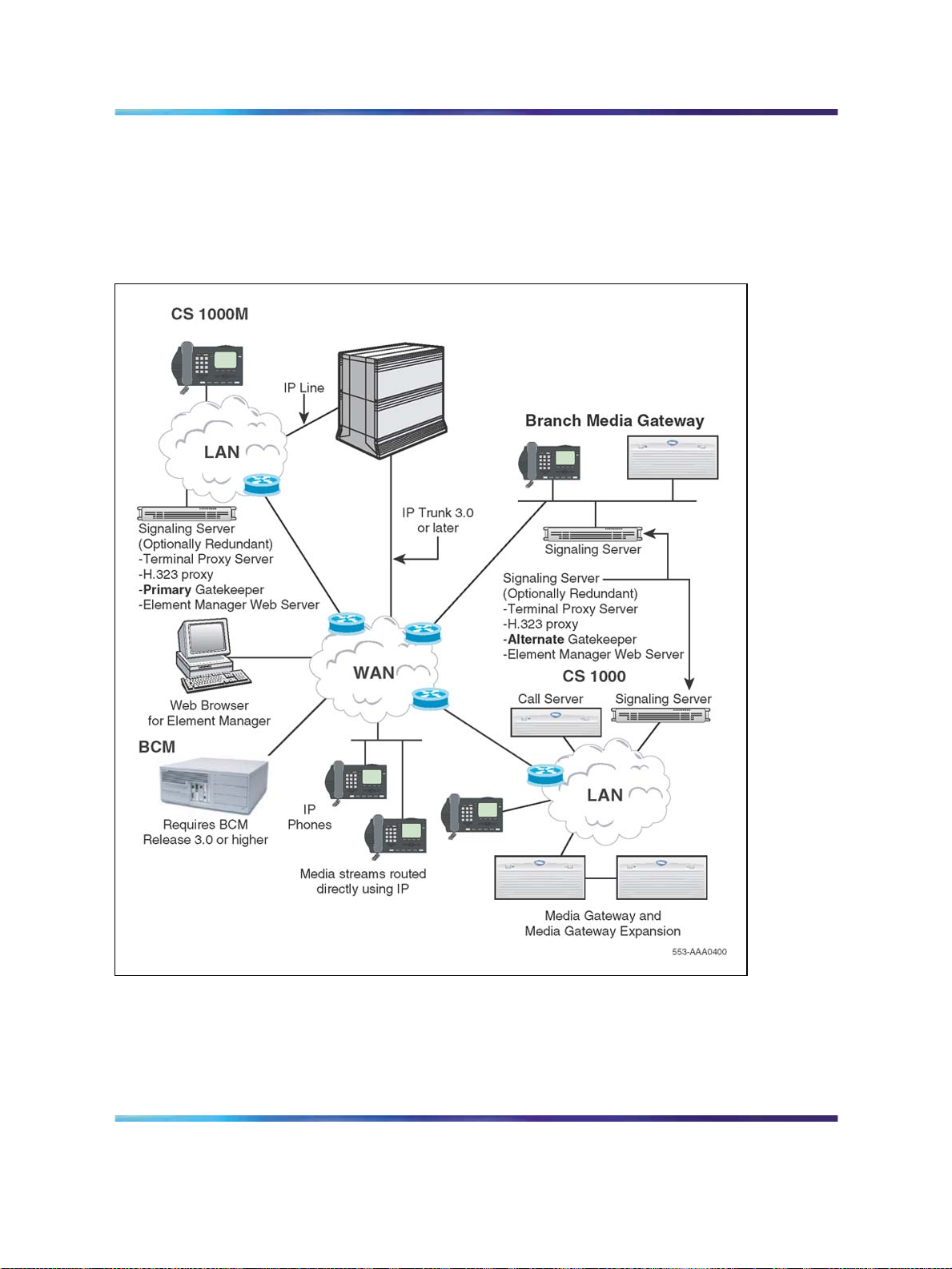
Interworking
The IP Phone uses the IP network to communicate with the LTPS and the
optional DHCP server. Figure 1 "System architecture" (page 21) shows a
diagram of the system architecture.
Figure 1
System architecture
Applicable systems 21
Applicable systems
The CS 1000 system supports the Media Card 32-port line card, Media
Card 32S card, and ITG-Pentium 24-port line card.
Copyright © 2003–2008, Nortel Networks
.
Nortel Communication Server 1000
IP Line Fundamentals
NN43100-500 02.02 Standard
Release 5.5 4 February 2008

22 Description
Unsupported products
The following remote service products do not support the Media Card
32-port line card, Media Card 32S card, and ITG-Pentium 24-port line card:
•
Carrier Remote
•
Mini-carrier Remote
•
Fiber Remote
•
Fiber Remote Multi-IPE
System requirements
CS 1000 Release 5.5 software is the minimum system software for IP Line.
Element Manager and Telephony Manager 3.1
In CS 1000 Release 5.5, Element Manager is the primary interface for Voice
Gateway Media Cards and IP Line.
Telephony Manager (TM) 3.1 is used only to obtain Operational
Measurement (OM) reports. TM 3.1 is the minimum required version.
CS 1000 systems
Element Manager is used as the configuration, administration, and
maintenance interface for IP Line on a CS 1000 system.
If you are trying to use TM 3.1 to perform an action available through
Element Manager, then TM 3.1 launches Element Manager automatically.
Corporate Directory
TM 3.1 is necessary for creation of the Corporate Directory database.
SNMP and alarms
Element Manager does not provide an SNMP alarm browser. Nortel
recommends you use TM 3.1 Alarm Manager when SNMP alarm collection
is required.
System configurations
Although IP Line can be used in different system configurations and its use
can vary in those configurations, there are two basic system configurations
supported in CS 1000 Release 5.5. See Table 1 "Possible system
configurations" (page 23).
Copyright © 2003–2008, Nortel Networks
.
Nortel Communication Server 1000
IP Line Fundamentals
NN43100-500 02.02 Standard
Release 5.5 4 February 2008

Table 1
Possible system configurations
System Signaling Server present
CS 1000E Yes
CS 1000M Yes
CS 1000 systems
CS 1000 systems have a Signaling Server in their network configuration.
The Signaling Server is a server that provides signaling interfaces to the
IP network. The Signaling Server central processor drives the signaling for
IP Phones and IP Peer networking.
In IP Line, the LTPS executes on the Signaling Server, and the voice
gateway executes on the Voice Gateway Media Cards. All IP Phones
register with the Signaling Server. The Voice Gateway Media Cards only
provide access to the voice gateway.
The Signaling Server is the node leader and, by default, acts as a Master
for the node.
System configurations 23
Signaling Servers
The following Signaling Servers are available for CS 1000 Release 5.0:
•
ISP1100
•
HP-DL320-G4
•
IBM-X306m
•
Common Processor Pentium Mobile (CP PM)
For further information about Signaling Server hardware platforms, see
Signaling Server Installation and Commissioning (NN43001-312).
In a CS 1000 system, the Signaling Servers can be used in Leader/Follower
and Primary/Alternate/Failsafe combinations.
In CS 1000 Release 5.5, the Signaling Servers support the following
applications:
•
Line Terminal Proxy Server (LTPS)
•
Virtual Trunk
•
H.323 Gateway
•
SIP Gateway
•
SIP Redirect Server
•
Network Routing Service (NRS)
Copyright © 2003–2008, Nortel Networks
.
Nortel Communication Server 1000
IP Line Fundamentals
NN43100-500 02.02 Standard
Release 5.5 4 February 2008

24 Description
•
Personal Directory
•
SIP Proxy Server (SPS)
•
Element Manager
Signaling Server redundancy Signaling Server redundancy ensures that
telephony services can withstand single hardware and network failures.
Several Signaling Servers can load share when the system contains multiple
Signaling Servers or Voice Gateway Media Cards. One Signaling Server is a
Leader Signaling Server that acts as the primary, or master, Terminal Proxy
Server (TPS). The other Signaling Server is a Follower Signaling Server
that acts as the backup, or secondary redundant TPS. There are several
methods of redundancy for a Signaling Server. See Table 2 "Methods of
Signaling Server redundancy" (page 24).
Table 2
Methods of Signaling Server redundancy
Stage
With a Signaling Server to share the load
1
2
3
4
Without a Signaling Server to share the load
1
2
Description
A Signaling Server, which shares the load, can be configured in a normal
configuration.
If the primary Signaling Server fails, the Signaling Server, which shares the load,
takes over and all IP Phones register with this Signaling Server.
If the Signaling Server, which shares the load, fails, one of the Voice Gateway Media
Cards is elected to be the node Master.
The IP Phones then register to the Voice Gateway Media Cards.
If there is no Signaling Server to share the load, and the primary Signaling Server
fails, one of the Voice Gateway Media Cards is elected to be the node Master.
The IP Phones then register to the Voice Gateway Media Cards.
Software delivery
IP Line supports software delivery through the following formats:
1. CompactFlash
2. Signaling Server CD-ROM
You must download the file of Product Category: VoIP & Multimedia
Communications, Product Name: IP-Enabled & Pure IP Networks, Product
Name: Signaling Server and IP Peer Networking, Content type: Release.
Obtain the precise Release, Status, and Title of the file from your next
level of support. See w
instructions.
Copyright © 2003–2008, Nortel Networks
.
ww.nortel.com/downloadingcontentfor download
Nortel Communication Server 1000
IP Line Fundamentals
NN43100-500 02.02 Standard
Release 5.5 4 February 2008

Required packages
The IP Phones require the software packages listed in Table 3 "Required
packages" (page 25).
Table 3
Required packages
Package Package number
Fax/Modem pass through 25
M2000 Digital Sets (DSET)
Aries Digital Sets (ARIE)
To configure IP Line in groups five to seven on Option 81C CP PII or CS 1000M
MG, the Fiber Network (FIBN) software package 365 is required.
Fax/Modem pass through
The Fax/Modem pass through feature provides a modem pass through
allowed (MPTA) class of service (CLS) for an analog phone TN. MPTA CLS
dedicates an analog phone TN to a modem or a Fax machine terminal. A
connection that initiates from the dedicated TN, and/or calls that terminate
at the dedicated TN through a Digital Signal Processor (DSP), use a G711
NO VAD codec on the Call Server.
Modem Pass through is a specific configuration of a G.711 VoIPchannel that
improves modem performance compared to standard VoIP configuration.
Auto switch to Voice Band Data (VBD) is a feature of the DSP; the DSP
monitors the data stream to distinguish between voice and data calls. The
DSP reconfigures to modem pass through mode when it determines the
call is a modem call.
88
170
ATTENTION
For modem calls between CS 1000 systems connected by analog and digital
trunks, you must configure MPTA CLS on the Call Server of each CS 1000
system for analog units connected to modems. MPTA CLS configuration is
necessary because the call setup negotiation is not done end to end as it is
for virtual trunks. If the analog unit on one Call Server uses MPTA CLS and
the analog unit on the other Call Server uses modem pass through denied
(MPTD) CLS, the modem call fails.
MPT CLS is supported by the G.711 codec only; MPT CLS includes no other
codecs. The packet interval for G.711 codec is set to 20 msecs in MPT.
The maximum speed supported for modem and fax is 33.6 Kbps. This limit
is imposed by the analog line card.
MPT allows CS 1000 to support the following:
•
modem pass through
•
Super G3(SG3) fax at V.34(33.6Kbps)
Copyright © 2003–2008, Nortel Networks
.
Nortel Communication Server 1000
IP Line Fundamentals
NN43100-500 02.02 Standard
Release 5.5 4 February 2008

26 Description
•
V.34 rate (33.6 Kbps) modems
•
Fax machines that support V.17, V.27, V.29, and V.34
For interface commands, responses, and definitions for MPT, see Table 4
"Interface commands and responses" (page 26).
Table 4
Interface commands and responses
Command prompt
CLS MPTA Turn on the MPT feature.
CLS MPTD Turn off the MPT feature.
User response Description
ATTENTION
CLS MPTA and CLS MPTD are included in LD 10 for analog line card units.
For information on feature packaging requirements, see Table 5 "Feature
packaging requirements" (page 26).
Table 5
Feature packaging requirements
Package
mnemonic
Softswitch
IPMG
Package
number
402
403
Package description Package type
(new, existing,
or dependency)
Identifies a softswitch
system.
Identifies a system that
is equipped with IPMGs.
Existing All
Existing All
Applicable
market
Modem traffic
CS 1000E supports modem traffic in a campus-distributed network with
the following characteristics:
•
Media card configuration:
— G.711 codec
— 20 msec packet size
•
one-way delay less than 5 msec
•
low packet loss
•
V.34 rate (33.6 Kbps)
Performance degrades significantly with packet loss.
Copyright © 2003–2008, Nortel Networks
.
Nortel Communication Server 1000
IP Line Fundamentals
NN43100-500 02.02 Standard
Release 5.5 4 February 2008

Nortel has conducted extensive but not exhaustive tests of modem-to-modem
calls, data transfers, and file transfers between a CS 1000E and MG 1000E, using
Virtual Trunks and PRI tandem trunks. While all tests have been successful,
Nortel cannot guarantee that all modem brands will operate properly over all
G.711 Voice over IP (VoIP) networks. Before deploying modems, test the modem
brand within the network to verify reliable operation. Contact your system supplier
or your Nortel representative for more information.
Voice Gateway Media Cards
Voice Gateway Media Card is a term used to encompass the Media Card
32-port card, ITG-P 24-port line card, and the Media Card 32S card. These
cards plug into an Intelligent Peripheral Equipment (IPE) shelf in the CS
1000M systems and into a Media Gateway 1000E and Media Gateway
1000E Expander in the CS 1000E system.
The ITG-P 24-port line card occupies two slots, while the Media Card
32-port and the Media Card 32S card occupy one slot.
The Media Card 32S card provides the following features:
Voice Gateway Media Cards 27
ATTENTION
Table 6
Card comparison
Item
•
Secure Real-time Transport Protocol (SRTP)
•
two Digital Signal Processors (DSP), based on an ARM processor
•
channel density of 32 ports
•
cost improvement over existing Media Cards
The Media Card 32-port card provides the following features:
•
32-port card packet processing power is greater than that of the ITG-P
24-port line card
• increases the channel density from 24 to 32 ports (for the 32-port
version)
•
reduces the slot count from a dual IPE slot to a single IPE slot
•
supports up to 128 IP Phones in failover scenarios
Table 6 "Card comparison " (page 27) provides a comparison of the ITG-P
24-port line card, Media Card 32-port card, and the MC 32S card.
ITG-P 24-port card Media Card 32-port
card
Media Card 32S card
Total DSP Channels
Copyright © 2003–2008, Nortel Networks
.
24 32 32
Nortel Communication Server 1000
IP Line Fundamentals
NN43100-500 02.02 Standard
Release 5.5 4 February 2008

28 Description
Item
ITG-P 24-port card Media Card 32-port
Media Card 32S card
card
Number of slots the
211
card occupies
Operating System VxWorks 5.3 VxWorks 5.4 VxWorks 5.5
Processor Pentium IXP1200 ARM920T
Contains two ARM
processors, one that
runs VxWorks and one
that runs the Mindspeed
application.
DSP 8 x TI5409 4 x TI5421 32 DSP channels
provided on a second
processor
Telogy version
7.01
8.1 High Density
version (8 ports for
DSP code is provided
by Mindspeed.
each DSP)
Number of IP Phones
96 128 128
that can register on
each LTPS
The IP Phones register to the Signaling Server. If the Signaling Server fails, the IP Phones register
to the Voice Gateway Media Card. A Signaling Server can register a maximum of 5000 IP Phones.
Image file name
IPL P IPL SA IPL ARM
prefixes shown by
swVersionShow
command
/C: drive On board Flash 2 x 4Mb Plug-in CompactFlash
32 Mb
Upgrade Two images files One image file (no
backup)
ATTENTION
In a CS 1000 system, the ELAN (Embedded LAN) subnet isolates critical
telephony signaling between the Call Server and the other components. The
ELAN subnet is also known as the Embedded LAN subnet. The TLAN (Telephony
LAN) subnet carries telephony, voice, and signaling traffic. The TLAN subnet, also
known as the Voice LAN subnet, connects to the customer network.
Voice Gateway Media Cards have an ELAN network interface (10BaseT)
and a TLAN network interface (10/100BaseT) on the I/O panel.
There is an RS-232 Maintenance Port connection on the faceplates of both
the ITG-P 24-port card and the Media Cards. The ITG-P 24-port card has
an alternative connection to the same serial port on the I/O backplane.
CompactFlash 128 Mb
One zipped package
Copyright © 2003–2008, Nortel Networks
.
Nortel Communication Server 1000
IP Line Fundamentals
NN43100-500 02.02 Standard
Release 5.5 4 February 2008

Capacity
Voice Gateway Media Cards 29
CAUTION
Do not connect maintenance terminals to both the faceplate and
the I/O panel serial maintenance port connections at the same
time.
The Virtual TN (VTN) feature allows each Voice Gateway Media Card to
support more IP Phones than there are physical bearer channels. There
are 24 bearer channels on each ITG-P card and 32 channels on each
Media Card.
Both cards support a 4:1 concentration of registered IP Phones (IP Phone
2001, IP Phone 2002, IP Phone 2004, IP Phone 2007, IP Audio Conference
Phone 2033, IP Softphone 2050, Mobile Voice Client [MVC] 2050, IP Phone
1110, IP Phone 1120E, IP Phone 1140E, IP Phone 1150E, IP Phone 1210,
IP Phone 1220, IP Phone 1230, WLAN Handset 2210, WLAN Handset
2211, WLAN Handset 2212, WLAN Handset 6120, WLAN Handset 6140 to
gateway channels. The ITG-P supports 96 registered IP Phones. The Media
Cards supports 128 registered IP Phones (when the card has 32 channels).
The IP Phones require the services of the bearer channels only when
they are busy on a call that requires a Time Division Multiplexing (TDM)
circuit such as an IP Phone-to-digital telephone/trunk/voice mail/conference.
When an IP Phone is idle or there is an IP-to-IP call, no gateway channel
is required.
When the total number of IP Phones that are registered or are attempting
to register reaches the limit (96 on the ITG-P or 128 on the Media Cards),
the Voice Gateway Media Card recognizes this, and no more IP Phones
are assigned to the card. Each Voice Gateway Media Card is restricted to
a total of 1200 call attempts per hour distributed across all the IP Phones
associated with the card.
Voice Gateway Media Card controls, indicators, and connectors
The following sections show the faceplates and describe the faceplate
components of the following Media Cards:
•
Figure 2 "Media Card 32-port " (page 30)
•
Figure 3 "ITG-P 24-port card faceplate" (page 32)
•
Figure 5 "Media Card 32S card faceplate" (page 38)
Copyright © 2003–2008, Nortel Networks
.
Nortel Communication Server 1000
IP Line Fundamentals
NN43100-500 02.02 Standard
Release 5.5 4 February 2008
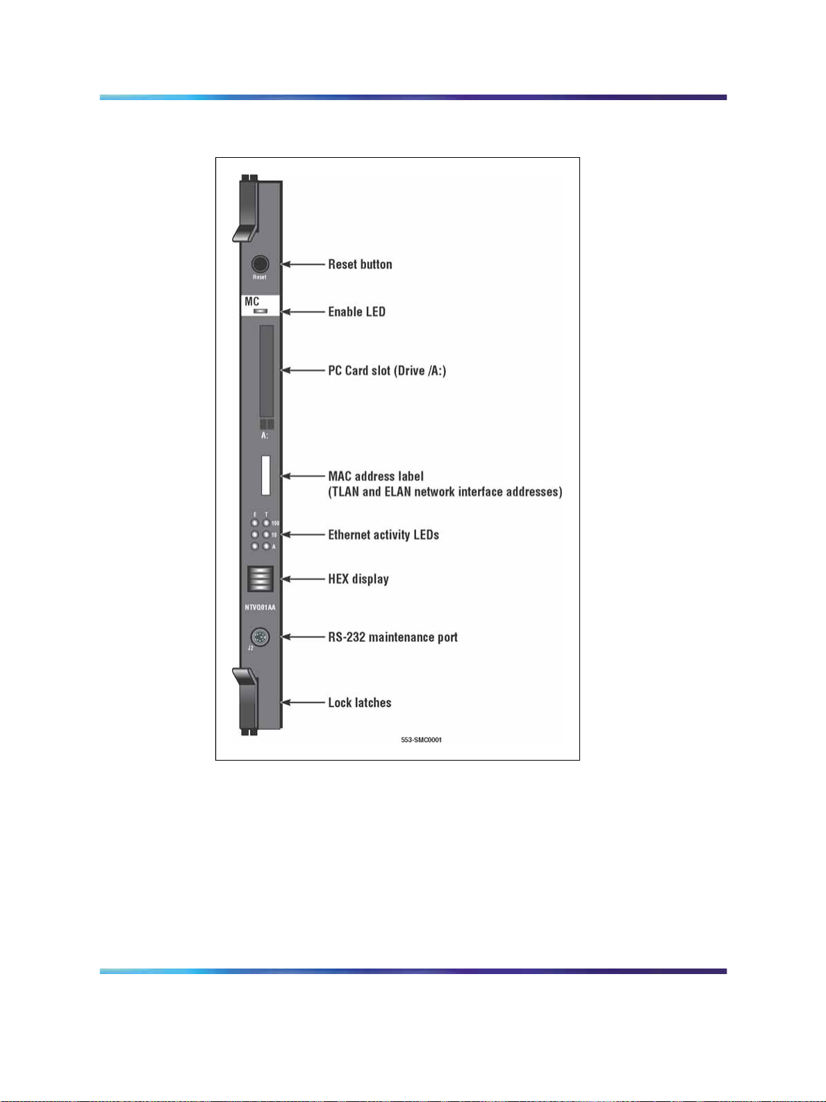
30 Description
Figure 2
Media Card 32-port
Faceplate components
The components on the faceplate of the Media Card 32-port card are
described in the following sections.
Reset button
Use the Reset button on the faceplate to manually reset the Media Card.
This enables the card to be reset without cycling power to it. The Reset
button is used to reboot the card after a software upgrade or to clear a
fault condition.
Copyright © 2003–2008, Nortel Networks
.
Nortel Communication Server 1000
IP Line Fundamentals
NN43100-500 02.02 Standard
Release 5.5 4 February 2008
 Loading...