

Page 1

Avaya Media Processing Server Series System
Reference Manual
(Software Release 2.1)
Avaya Business Communications Manager
Release 6.0
Document Status: Standard
Document Number: P0602477
Document Version: 3.1.12
Date: June 2010
Page 2

© 2010 Avaya Inc.
All Rights Reserved.
Notices
While reasonable efforts have been made to ensure that the information in this document is complete and accurate at the time of printing,
Avaya assumes no liability for any errors. Avaya reserves the right to make changes and corrections to the information in this document
without the obligation to notify any person or organization of such changes.
Documentation disclaimer
Avaya shall not be responsible for any modifications, additions, or deletions to the original published version of this documentation
unless such modifications, additions, or deletions were performed by Avaya. End User agree to indemnify and hold harmless Avaya,
Avaya’s agents, servants and employees against all claims, lawsuits, demands and judgments arising out of, or in connection with,
subsequent modifications, additions or deletions to this documentation, to the extent made by End User.
Link disclaimer
Avaya is not responsible for the contents or reliability of any linked Web sites referenced within this site or documentation(s) provided by
Avaya. Avaya is not responsible for the accuracy of any information, statement or content provided on these sites and does not
necessarily endorse the products, services, or information described or offered within them. Avaya does not guarantee that these links will
work all the time and has no control over the availability of the linked pages.
Warranty
Avaya provides a limited warranty on this product. Refer to your sales agreement to establish the terms of the limited warranty. In
addition, Avaya’s standard warranty language, as well as information regarding support for this product, while under warranty, is
available to Avaya customers and other parties through the Avaya Support Web site: http://www.avaya.com/support
Please note that if you acquired the product from an authorized reseller, the warranty is provided to you by said reseller and not by Avaya.
Licenses
THE SOFTWARE LICENSE TERMS AVAILABLE ON THE AVAYA WEBSITE, HTTP://SUPPORT.AVAYA.COM/LICENSEINFO/
ARE APPLICABLE TO ANYONE WHO DOWNLOADS, USES AND/OR INSTALLS AVAYA SOFTWARE, PURCHASED FROM
AVAYA INC., ANY AVAYA AFFILIATE, OR AN AUTHORIZED AVAYA RESELLER (AS APPLICABLE) UNDER A
COMMERCIAL AGREEMENT WITH AVAYA OR AN AUTHORIZED AVAYA RESELLER. UNLESS OTHERWISE AGREED TO
BY AVAYA IN WRITING, AVAYA DOES NOT EXTEND THIS LICENSE IF THE SOFTWARE WAS OBTAINED FROM ANYONE
OTHER THAN AVAYA, AN AVAYA AFFILIATE OR AN AVAYA AUTHORIZED RESELLER, AND AVAYA RESERVES THE
RIGHT TO T AKE LEGAL ACTION AGAINST YOU AND ANYONE ELSE USING OR SELLING THE SOFTWARE WITHOUT A
LICENSE. BY INSTALLING, DOWNLOADING OR USING THE SOFTWARE, OR AUTHORIZING OTHERS TO DO SO, YOU,
ON BEHALF OF YOURSELF AND THE ENTITY FOR WHOM YOU ARE INSTALLING, DOWNLOADING OR USING THE
SOFTWARE (HEREINAFTER REFERRED TO INTERCHANGEABLY AS "YOU" AND "END USER"), AGREE TO THESE
TERMS AND CONDITIONS AND CREATE A BINDING CONTRACT BETWEEN YOU AND AVAYA INC. OR THE
APPLICABLE AVAYA AFFILIATE ("AVAYA").
Copyright
Except where expressly stated otherwise, no use should be made of the Documentation(s) and Pr oduct( s) p rovided by Avaya. All content
in this documentation(s) and the product(s) pr ov id ed by Avaya including the selection, arrangement and design of the content is owned
either by Avaya or its licensors and is protected b y copyright and other intellectual property laws including the sui generis rights relating
to the protection of databases. You may not modify, copy, reproduce, republish, upload, post, transmit or distribute in any way any
content, in whole or in part, including any code and software. Unauthorized reproduction, transmission, dissemination, storage, and or
use without the express written consent of Avaya can be a criminal, as well as a civil offense under the applicable law.
Third Party Components
Certain software programs or portions thereof included in the Product may contain software distributed under third party agreements
("Third Party Components"), which may contain terms that expand or limit rights to use certain portions of the Product ("Third Party
Terms" ). Information regarding distributed Linux OS source code (for those Products that have distributed the Linux OS source code),
and identifying the copyright holders of the Third Party Components and the Third Party Terms that apply to them is available on the
Avaya Support Web site: http://support.avaya.com/Copyright.
Trademarks
The trademarks, logos and service marks ("Marks") displayed in this site, the documentation(s) and product(s) pr ovided by Avaya are the
registered or unregistered Marks of Avaya, its affiliates, or other third parties. Users are not permitted to use such Marks without prior
written consent from A vaya or such third party which may own the Mark. Nothing contained in this site, the documentation(s) and
product(s) should be construed as granting, by implication, estoppel, or otherwise, any license or right in and to the Marks without the
express written permission of Avaya or the applicable third party. Avaya is a registered trademark of Avaya Inc. All non-Avaya
trademarks are the property of their respective owners.
Downloading documents
For the most current versions of documentation, see the Avaya Support. Web site: http://www.avaya.c om/support
Contact Avaya Support
Avaya provides a telephone number for you to use to report problems or to ask questions about your product. The support telephone
number is 1-800-242-2121 in the United States. For additional support telephone numbers, see the Avaya Web site: http://
www.avaya.com/support
Page 3

Table of Contents
Table of Contents
Preface . . . . . . . . . . . . . . . . . . . . . . . . . . . . . . . . . . . . . . . . . . . . 9
Scope . . . . . . . . . . . . . . . . . . . . . . . . . . . . . . . . . . . . . . . . . . . . . . 10
Intended Audience . . . . . . . . . . . . . . . . . . . . . . . . . . . . . . . . . . . . 10
How to Use This Manual . . . . . . . . . . . . . . . . . . . . . . . . . . . . . . . 11
Organization of This Manual . . . . . . . . . . . . . . . . . . . . . . . . . . . . 12
Conventions Used in This Manual . . . . . . . . . . . . . . . . . . . . . . . . 13
Solaris and Windows 2000 Conventions . . . . . . . . . . . . . . . . . . . 15
Trademark Conventions . . . . . . . . . . . . . . . . . . . . . . . . . . . . . . . . 15
Avaya MPS Architectural Overview . . . . . . . . . . . . . . . . . . 17
Overview of the Avaya Media Processing Server (MPS) System 18
System Architecture . . . . . . . . . . . . . . . . . . . . . . . . . . . . . . . . . . . 19
Hardware Overview . . . . . . . . . . . . . . . . . . . . . . . . . . . . . . . . . . . 21
Front Control Panel (FCP) . . . . . . . . . . . . . . . . . . . . . . . . . . 22
Variable Resource Chassis (VRC) . . . . . . . . . . . . . . . . . . . . 22
Power Supplies . . . . . . . . . . . . . . . . . . . . . . . . . . . . . . . . 24
VRC Rear Panel . . . . . . . . . . . . . . . . . . . . . . . . . . . . . . . 26
Drive Bays . . . . . . . . . . . . . . . . . . . . . . . . . . . . . . . . . . . 26
Application Processor . . . . . . . . . . . . . . . . . . . . . . . . . . . 26
Network Interface Controller (NIC) or Hub-NIC . . . . . . 27
Telephony Media Server (TMS). . . . . . . . . . . . . . . . . . . . . . 28
Phone Line Interface . . . . . . . . . . . . . . . . . . . . . . . . . . . . 28
Multiple DSP Module (MDM) . . . . . . . . . . . . . . . . . . . . 31
System LAN Interface . . . . . . . . . . . . . . . . . . . . . . . . . . 32
Field Programmable Gate Arrays (FPGA) and the Boot
ROM . . . . . . . . . . . . . . . . . . . . . . . . . . . . . . . . . . . . . . . . 32
TelCo Connector Panel (TCCP) . . . . . . . . . . . . . . . . . . . . . 33
Software Overview . . . . . . . . . . . . . . . . . . . . . . . . . . . . . . . . . . . 34
Software Environment . . . . . . . . . . . . . . . . . . . . . . . . . . 35
ASE Processes . . . . . . . . . . . . . . . . . . . . . . . . . . . . . . . . 36
ASE/VOS Integration Layer . . . . . . . . . . . . . . . . . . . . . . 39
VOS Processes . . . . . . . . . . . . . . . . . . . . . . . . . . . . . . . . 39
System Utilities and Software . . . . . . . . . . . . . . . . . . . . . . . . . . . 51
alarm . . . . . . . . . . . . . . . . 51
dlog . . . . . . . . . . . . . . . . . . . . . . . . . . . . . . . . . . . . . . . . . . 52
dlt . . . . . . . . . . . . . . . . . . . . . . . . . . . . . . . . . . . . . . . . . . . 53
log . . . . . . . . . . . . . . . . . . . . . . . . . . . . . . . . . . . . . . . . . . . 53
PeriProducer . . . . . . . . . . . . . . . . . . . . . . . . . . . . . . . . . . . . . 54
PeriReporter . . . . . . . . . . . . . . . . . . . . . . . . . . . . . . . . . . . . . 55
PeriStudio . . . . . . . . . . . . . . . . . . . . . . . . . . . . . . . . . . . . . . . 56
PeriView . . . . . . . . . . . . . . . . . . . . . . . . . . . . . . . . . . . . . . . . 57
PeriWeb . . . . . . . . . . . . . . . . . . . . . . . . . . . . . . . . . . . . . . . . 59
vsh . . . . . . . . . . . . . . . . . 60
# P0602477 Ver: 3.1.11 Page 3
Page 4

Avaya Media Processing Server Series System Reference Manual
Base System Configuration . . . . . . . . . . . . . . . . . . . . . . . . . . 63
Base System Configuration . . . . . . . . . . . . . . . . . . . . . . . . . . . . . 64
System Startup . . . . . . . . . . . . . . . . . . . . . . . . . . . . . . . . . . . . . . . 65
Solaris Startup/Shutdown . . . . . . . . . . . . . . . . . . . . . . . . . . . 67
Windows Startup/Shutdown . . . . . . . . . . . . . . . . . . . . . . . . . 69
SRP (Startup and Recovery Process) . . . . . . . . . . . . . . . . . . 70
Manually Starting and Stopping SRP . . . . . . . . . . . . . . . 70
VPS Topology Database Server (VTDB) . . . . . . . . . . . . 71
Restart of Abnormally Terminated Programs . . . . . . . . . 72
Communication with VOS Processes . . . . . . . . . . . . . . . 72
SRP Configuration Command Line Arguments . . . . . . . 74
VSH Shell Commands . . . . . . . . . . . . . . . . . . . . . . . . . . 75
SRP Status . . . . . . . . . . . . . . . . . . . . . . . . . . . . . . . . . . . . 81
Call Control Manager (CCM/CCMA) . . . . . . . . . . . . . . . . . 82
Startup Files . . . . . . . . . . . . . . . . . . . . . . . . . . . . . . . . . . . . . 83
The hosts File . . . . . . . . . . . . . . . . . . . . . . . . . . . . . . . 83
User Configuration Files . . . . . . . . . . . . . . . . . . . . . . . . . . . . . . . 86
The .xhtrahostsrc File. . . . . . . . . . . . . . . . . . . . . . . . . 86
The MPSHOME Directory . . . . . . . . . . . . . . . . . . . . . . . . . . . . . . . 87
The MPSHOME/common Directory . . . . . . . . . . . . . . . . . . . . . . 88
The MPSHOME/common/etc Directory . . . . . . . . . . . . . . 88
The srp.cfg File . . . . . . . . . . . . . . . . . . . . . . . . . . . . . 89
The vpshosts File . . . . . . . . . . . . . . . . . . . . . . . . . . . . 93
The compgroups File . . . . . . . . . . . . . . . . . . . . . . . . . 95
The gen.cfg File . . . . . . . . . . . . . . . . . . . . . . . . . . . . . 96
The global_users.cfg File . . . . . . . . . . . . . . . . . . 98
The alarmd.cfg and alarmf.cfg Files . . . . . . . . . 99
The pmgr.cfg File . . . . . . . . . . . . . . . . . . . . . . . . . . . 100
The periview.cfg File . . . . . . . . . . . . . . . . . . . . . . 102
The MPSHOME/common/etc/tms Directory . . . . . . . . 103
The sys.cfg File . . . . . . . . . . . . . . . . . . . . . . . . . . 103
The tms.cfg File . . . . . . . . . . . . . . . . . . . . . . . . . . . 106
Protocol Configuration Files . . . . . . . . . . . . . . . . . . . . . . . 123
The $MPSHOME/packages Directory . . . . . . . . . . . . . . 125
%MPSHOME%\PERIase - /opt/vps/PERIase. . 127
The /etc/ase.conf file . . . . . . . . . . . . . . . . . . . . . 127
The /etc/services File . . . . . . . . . . . . . . . . . . . . . 129
%MPSHOME%\PERIbrdge - /opt/vps/PERIbrdge 132
%MPSHOME%\PERIdist - /opt/vps/PERIdist. 133
%MPSHOME%\PERIglobl - /opt/vps/PERIglobl 133
%MPSHOME%\PERIview - /opt/vps/PERIview. 134
%MPSHOME%\PERIplic - /opt/vps/PERIplic. 134
%MPSHOME%\PERItms -
The /cfg/atm_triplets.cfg File . . . . . . . . . . . 135
The /cfg/ps_triplets.cfg File . . . . . . . . . . . . 136
/opt/vps/PERItms. . 134
Page 4 # P0602477 Ver: 3.1.11
Page 5

Table of Contents
The /cfg/tms_triplets.cfg File . . . . . . . . . . . 136
%MPSHOME%\PERImps - /opt/vps/PERImps . 137
The MPSHOME/tmscommN Directory. . . . . . . . . . . . . . . . 138
MPS 500 . . . . . . . . . . . . . . . . . . . . . . . . . . . . . . . . . . . . 138
MPS 1000 . . . . . . . . . . . . . . . . . . . . . . . . . . . . . . . . . . . 138
The MPSHOME/mpsN Directory . . . . . . . . . . . . . . . . . . . . 139
The MPSHOME/mpsN/apps Directory . . . . . . . . . . . 140
The MPSHOME/mpsN/etc Directory . . . . . . . . . . . . . 142
VMM Configuration Files . . . . . . . . . . . . . . . . . . . . . . . . . 144
The vmm.cfg File . . . . . . . . . . . . . . . . . . . . . . . . . . . . 144
The vmm-mmf.cfg File . . . . . . . . . . . . . . . . . . . . . . . 146
ASE Configuration Files. . . . . . . . . . . . . . . . . . . . . . . . . . . 148
The ase.cfg File . . . . . . . . . . . . . . . . . . . . . . . . . . . . 148
The aseLines.cfg File . . . . . . . . . . . . . . . . . . . . . . 149
CCM Configuration Files . . . . . . . . . . . . . . . . . . . . . . . . . . 151
The ccm_phoneline.cfg File . . . . . . . . . . . . . . . . 151
The ccm_admin.cfg File . . . . . . . . . . . . . . . . . . . . . 155
TCAD Configuration Files . . . . . . . . . . . . . . . . . . . . . . . . . 157
The tcad-tms.cfg File . . . . . . . . . . . . . . . . . . . . . . 157
The tcad.cfg File . . . . . . . . . . . . . . . . . . . . . . . . . . . 158
TRIP Configuration Files . . . . . . . . . . . . . . . . . . . . . . . . . . 159
The trip.cfg File . . . . . . . . . . . . . . . . . . . . . . . . . . . 159
TMS Watchdog Functions . . . . . . . . . . . . . . . . . . . . . . . . . 160
Common Configuration . . . . . . . . . . . . . . . . . . . . . . . . . . . . 163
Multi-Media Format Files (MMFs) . . . . . . . . . . . . . . . . . . . . . . 164
How to Create an MMF File. . . . . . . . . . . . . . . . . . . . . . . . 164
Vocabulary MMF Files vs. CMR MMF Files . . . . . . . . . . 165
Activating MMF Files . . . . . . . . . . . . . . . . . . . . . . . . . . . . 166
Delimited and Partial Loading . . . . . . . . . . . . . . . . . . . 168
Audio Playback . . . . . . . . . . . . . . . . . . . . . . . . . . . . . . . 169
Custom Loading . . . . . . . . . . . . . . . . . . . . . . . . . . . . . . 171
Using Hash Tables . . . . . . . . . . . . . . . . . . . . . . . . . . . . . . . 172
System MMF Files . . . . . . . . . . . . . . . . . . . . . . . . . . . . 173
Application-Specific MMF Files . . . . . . . . . . . . . . . . . 174
Default Vocabulary and Record MMF Files . . . . . . . . 175
Diagnostics and Reports . . . . . . . . . . . . . . . . . . . . . . . . . . . 176
Synchronizing MMF Files Across Nodes. . . . . . . . . . . . . . 177
ZAP and MMF files on the MPS . . . . . . . . . . . . . . . . . 177
MMF Abbreviated Content (MAC) File . . . . . . . . . . . . 178
Basic Implementation (Low Volume/Traffic) . . . . . . . 178
Advanced Implementation (High Volume/Traffic) . . . 181
Updating a Specific Element . . . . . . . . . . . . . . . . . . . . 185
Exception Processing . . . . . . . . . . . . . . . . . . . . . . . . . . 187
Log Files . . . . . . . . . . . . . . . . . . . . . . . . . . . . . . . . . . . . 188
# P0602477 Ver: 3.1.11 Page 5
Page 6

Avaya Media Processing Server Series System Reference Manual
Synchronization (ZAP) Command Summary . . . . . . . . 191
Troubleshooting . . . . . . . . . . . . . . . . . . . . . . . . . . . . . . 194
Call Simulator Facility . . . . . . . . . . . . . . . . . . . . . . . . . . . . . . . . 195
VEMUL Script Format . . . . . . . . . . . . . . . . . . . . . . . . . . . . 195
Script Control . . . . . . . . . . . . . . . . . . . . . . . . . . . . . . . . . . . 196
Configuration Parameters . . . . . . . . . . . . . . . . . . . . . . . . . . 196
Script Commands . . . . . . . . . . . . . . . . . . . . . . . . . . . . . . . . 196
Statements . . . . . . . . . . . . . . . . . . . . . . . . . . . . . . . . . . . 197
Primitives . . . . . . . . . . . . . . . . . . . . . . . . . . . . . . . . . . . 198
Phone Line Behavior During Simulation . . . . . . . . . . . . . . 199
Call Simulator Conditions and Usage. . . . . . . . . . . . . . . . . 199
Command Line Interface . . . . . . . . . . . . . . . . . . . . . . . . . . 200
Example Call Simulation Script Files. . . . . . . . . . . . . . . . . 202
Alarm Filtering . . . . . . . . . . . . . . . . . . . . . . . . . . . . . . . . . . . . . 203
Filtering Precepts . . . . . . . . . . . . . . . . . . . . . . . . . . . . . . . . 204
Command Line Interface . . . . . . . . . . . . . . . . . . . . . . . . . . 205
alarmf Command Line Options . . . . . . . . . . . . . . . . 206
Notation Functionality . . . . . . . . . . . . . . . . . . . . . . . . . . . . 207
Logical Conditions . . . . . . . . . . . . . . . . . . . . . . . . . . . . 209
Action Functions . . . . . . . . . . . . . . . . . . . . . . . . . . . . . . 211
Filtering Examples . . . . . . . . . . . . . . . . . . . . . . . . . . . . . . . 213
Interapplication/Host Service Daemon Data Exchange . . . . . . . 215
VMST (VMS) . . . . . . . . . . . . . . . . . . . . . . . . . . . . . . . . . . . 215
Starting Under SRP . . . . . . . . . . . . . . . . . . . . . . . . . . . . 215
PeriPro Interaction . . . . . . . . . . . . . . . . . . . . . . . . . . . . 216
Arguments . . . . . . . . . . . . . . . . . . . . . . . . . . . . . . . . . . . 217
Examples: . . . . . . . . . . . . . . . . . . . . . . . . . . . . . . . . . . . 218
VTCPD . . . . . . . . . . . . . . . . . . . . . . . . . . . . . . . . . . . . . . . . 220
Single Connection to Host . . . . . . . . . . . . . . . . . . . . . . 221
Multiple Connections to Multiple Hosts . . . . . . . . . . . . 221
One Connection Per Line . . . . . . . . . . . . . . . . . . . . . . . 222
Multiple VTCPD Daemons . . . . . . . . . . . . . . . . . . . . . 222
Host Connections . . . . . . . . . . . . . . . . . . . . . . . . . . . . . 222
Attaching to VMST . . . . . . . . . . . . . . . . . . . . . . . . . . . 225
Message Format . . . . . . . . . . . . . . . . . . . . . . . . . . . . . . 227
Message Identification (ID) . . . . . . . . . . . . . . . . . . . . . 231
Connection Capacity . . . . . . . . . . . . . . . . . . . . . . . . . . . 233
Application-Host Interaction Configuration Options . . 234
Queuing Requests . . . . . . . . . . . . . . . . . . . . . . . . . . . . . 236
Monitoring Host Connections . . . . . . . . . . . . . . . . . . . . 238
Backup LAN . . . . . . . . . . . . . . . . . . . . . . . . . . . . . . . . . 239
VFTPD . . . . . . . . . . . . . . . . . . . . . . . . . . . . . . . . . . . . . . . . 240
Specifying a Port . . . . . . . . . . . . . . . . . . . . . . . . . . . . . . 240
Automatic Startup . . . . . . . . . . . . . . . . . . . . . . . . . . . . . 241
Automatic FTP Logins . . . . . . . . . . . . . . . . . . . . . . . . . 241
Identifying the Configured Host Computers . . . . . . . . 242
Page 6 # P0602477 Ver: 3.1.11
Page 7

Table of Contents
Configuration Procedures and Considerations . . . . . . . . . 243
Making Changes to an Existing System . . . . . . . . . . . . . . . . . . 244
Adding Spans . . . . . . . . . . . . . . . . . . . . . . . . . . . . . . . . . . . 244
Modifying the Span Resource Set . . . . . . . . . . . . . . . . . . . 244
Changing Pool/Class Names . . . . . . . . . . . . . . . . . . . . . . . 245
Renumbering a Component . . . . . . . . . . . . . . . . . . . . . . . . 245
Renaming a Solaris MPS Node . . . . . . . . . . . . . . . . . . . . . 246
Renaming a Windows MPS Node . . . . . . . . . . . . . . . . . . . 247
Introducing a New Node. . . . . . . . . . . . . . . . . . . . . . . . . . . 248
Enabling Statistics Collection. . . . . . . . . . . . . . . . . . . . . . . 249
Debug Terminal Connection . . . . . . . . . . . . . . . . . . . . . . . 250
Connection Using a Dumb Terminal or PC . . . . . . . . . 250
Connection from the System Console . . . . . . . . . . . . . 250
Verifying/Modifying Boot ROM Settings . . . . . . . . . . . . . . . . 252
DCC Boot ROM . . . . . . . . . . . . . . . . . . . . . . . . . . . . . . . . 252
TMS Boot ROM . . . . . . . . . . . . . . . . . . . . . . . . . . . . . . . . 256
NIC Boot ROM . . . . . . . . . . . . . . . . . . . . . . . . . . . . . . . . . 260
Resetting the NIC . . . . . . . . . . . . . . . . . . . . . . . . . . . . . 264
TMS Computer Telephony (CT) Bus Clocking . . . . . . . . . . . . 265
N+1 Redundancy . . . . . . . . . . . . . . . . . . . . . . . . . . . . . . . . . . . . 267
Sample MPS 1000 N+1 Redundancy System Configuration 267
TRIP Failback . . . . . . . . . . . . . . . . . . . . . . . . . . . . . . . . . . . 268
Directory Layout on a Secondary (Backup) Node . . . . . . . 269
Least Cost Routing Daemon . . . . . . . . . . . . . . . . . . . . . . . . 271
Redundancy Configuration Daemon (RCD). . . . . . . . . . . . 271
The Failover/Failback Process . . . . . . . . . . . . . . . . . . . . . . 273
Installation and Configuration . . . . . . . . . . . . . . . . . . . . . . 274
Create the Secondary Node . . . . . . . . . . . . . . . . . . . . . . 274
TMSCOMM Component Configuration . . . . . . . . . . . 274
Edit the vpshosts File . . . . . . . . . . . . . . . . . . . . . . . . . . 275
Edit the tms.cfg File . . . . . . . . . . . . . . . . . . . . . . . . . . . 276
Edit TRIP and RCD Configuration Files . . . . . . . . . . . 276
Edit the gen.cfg file . . . . . . . . . . . . . . . . . . . . . . . . . . . . 276
PMGR configuration . . . . . . . . . . . . . . . . . . . . . . . . . . . 277
Media Directories . . . . . . . . . . . . . . . . . . . . . . . . . . . . . 278
First Startup After Configuration . . . . . . . . . . . . . . . . . . . . 280
Verifying N+1 Functionality . . . . . . . . . . . . . . . . . . . . . . . 283
Failover . . . . . . . . . . . . . . . . . . . . . . . . . . . . . . . . . . . . . 283
Failback . . . . . . . . . . . . . . . . . . . . . . . . . . . . . . . . . . . . . 284
Speech Server Resources in N+1 Redundancy. . . . . . . . . . 285
Pool Manager (PMGR) . . . . . . . . . . . . . . . . . . . . . . . . . . . . . . . 288
Terminology . . . . . . . . . . . . . . . . . . . . . . . . . . . . . . . . . . . . 288
Resource Object . . . . . . . . . . . . . . . . . . . . . . . . . . . . . . 288
Allocation/Deallocation . . . . . . . . . . . . . . . . . . . . . . . . 288
Pool . . . . . . . . . . . . . . . . . . . . . . . . . . . . . . . . . . . . . . . . 289
# P0602477 Ver: 3.1.11 Page 7
Page 8

Avaya Media Processing Server Series System Reference Manual
Resource Identifier/String . . . . . . . . . . . . . . . . . . . . . . . 289
Scheme . . . . . . . . . . . . . . . . . . . . . . . . . . . . . . . . . . . . . 289
Configuration . . . . . . . . . . . . . . . . . . . . . . . . . . . . . . . . . . . 289
Port Service States . . . . . . . . . . . . . . . . . . . . . . . . . . . . 291
Network Failure Detection (Pinging) . . . . . . . . . . . . . . 291
Database Conversion . . . . . . . . . . . . . . . . . . . . . . . . . . . . . . . . . 292
Platform Conversion . . . . . . . . . . . . . . . . . . . . . . . . . . . . . . 292
Starting a Reader . . . . . . . . . . . . . . . . . . . . . . . . . . . . . . 292
Starting a Writer . . . . . . . . . . . . . . . . . . . . . . . . . . . . . . 292
Database Format Conversion . . . . . . . . . . . . . . . . . . . . . . . 293
Reader/Writer Synchronization . . . . . . . . . . . . . . . . . . . . . 293
File Size Limitations. . . . . . . . . . . . . . . . . . . . . . . . . . . . . . 293
Call Monitoring . . . . . . . . . . . . . . . . . . . . . . . . . . . . . . . . . . . . . 294
Listening to Calls . . . . . . . . . . . . . . . . . . . . . . . . . . . . . . . . 294
Security . . . . . . . . . . . . . . . . . . . . . . . . . . . . . . . . . . . . . . . . . 297
Antivirus Software . . . . . . . . . . . . . . . . . . . . . . . . . . . . . . . . . . . 298
Secure Shell . . . . . . . . . . . . . . . . . . . . . . . . . . . . . . . . . . . . . . . . 299
Index . . . . . . . . . . . . . . . . . . . . . . . . . . . . . . . . . . . . . . . . . . . 301
Page 8 # P0602477 Ver: 3.1.11
Page 9

Preface
Page 10

Avaya Media Processing Server Series System Reference Manual
Scope
The Avaya Media Processing Server Series System Reference Manual details the
procedures and parameters for configuring the Avaya Media Processing Server (MPS)
Series system for online operation in a variety of telephony environments. In addition,
this manual provides configuration parameters and basic file information for elements
common to all MPS within the network. Note, however, that though there are two
basic products available in the MPS system - a single rack-mounted version known as
the Avaya MPS Series and a cabinet enclosed network configuration which relies on
the MPS 500 - this manual deals almost exclusively with the latter.
In addition to this document, the Avaya Media Processing Server Series System
Operator’s Guide may be particularly helpful. They provide a road map through the
major functions in the daily operation and monitoring of the MPS system. For a list of
other user manuals, see the Reference Material link in PeriDoc.
Intended Audience
This manual is intended for the persons who will be configuring the MPS for a
specific site and/or maintaining it from a particular perspective. The reader should be
familiar with telecommunications and computer equipment, their functions, and
associated terminology. In addition, the reader must be familiar with the
characteristics of the specific installation site, including site-specific power systems,
computer systems, peripheral components, and telephone networks.
Some of the material covered here involves the configuration of basic and critical
MPS parameters. Small inaccuracies in the configuration of these parameters can
impede system performance. Individuals without highly specialized knowledge in this
area should not attempt to change the defaults.
This guide assumes that the user has completed an on-site system familiarization
training program conducted as part of the initial system installation. Basic knowledge
of the Solaris and/or Windows 2000 operating system(s) is also assumed.
Page 10 # P0602477 Ver: 3.1.11
Page 11

How to Use This Manual
This manual uses many standard terms relating to computer system and software
application functions. However, it contains some terminology that can only be
explained in the context of the MPS system. Refer to the Glossary of Avaya Media
Processing Server Series Terminology for definitions of product specific terms.
It is not essential that this document be read cover-to-cover, as the entire contents is
not universally applicable to all MPS environments. It is essential, however, that there
is a clear understanding of exactly what information pertains to your environment and
that you can identify, locate, and apply the information documented in this manual.
Later, you can use the Table of Contents to locate topics of interest for reference and
review.
If you are reading this document online, use the hypertext links to quickly locate
related topics. Click once with your mouse while positioned with your cursor over the
hypertext link. Click on any point in a Table of Contents entry to move to that topic.
Click on the page number of any Index entry to access that topic page. Use the
hyperlinks at the top and bottom of each HTML “page” to help you navigate the
documentation. Pass your cursor over the Avaya Globemark to display the title,
software release, publication number, document release, and release date for the
HTML manual you are using.
Preface
For additional related information, use the Reference Material link in PeriDoc. To
familiarize yourself with various specialized textual references within the manual, see
Conventions Used in This Manual on page 13.
Periphonics is now part of Avaya. The name Periphonics, and variations thereof,
appear in this manual only where it is referred to in a product. (For example, a
PeriProducer application, the PERImps package, the perirev command, etc.)
# P0602477 Ver: 3.1.11 Page 11
Page 12

Avaya Media Processing Server Series System Reference Manual
Organization of This Manual
This document is designed to identify the procedures and configuration parameters
required for successful MPS operations. It provides an overview of the MPS system
and proceeds to document both basic and common system parameters. The following
passages provide an overview of the information contained in each area of this
manual.
Chapter 1 - Avaya Media Processing Server Series Architectural Overview
Provides a description of the MPS system and an overview of its hardware
and software. Diagrams and describes the MPS structure, its software
processes, and identifies other system utilities.
Chapter 2 - Base System Configuration
Describes and diagrams the system directory structure and startup and
shutdown, delineates the Startup and Recovery Process (SRP), and details
MPSHOME and all required configuration files.
Chapter 3 - Common Configuration
Documents the facilities available on all (common) MPS platforms. Details
MultiMedia Format (MMF) file creation and utilization. Also covers call
simulation, alarm filtering, and exchange of data between applications, hosts,
and MPS.
Chapter 4 - Configuration Procedures and Considerations
Contains common procedures and comprehensive considerations for
modifying existing systems and adding features.
Appendix A - Process and Utility Command Summary
Lists commands for some of the processes and utilities most commonly
interacted with in the MPS system. Provides brief definitions for each and
links to more detailed information.
Appendix B - Avaya MPS Specifications
Contains physical, electrical, environmental, and interface specifications for
the MPS.
Page 12 # P0602477 Ver: 3.1.11
Page 13

Conventions Used in This Manual
This manual uses different fonts and symbols to differentiate between document
elements and types of information. These conventions are summarized in the
following table.
Conventions Used in This Manual Sheet 1 of 2
Notation Description
Preface
Normal text
important term
system
command
command,
condition
and alarm
file name /
directory
on-screen field
<KEY NAME>
Book Reference
Normal text font is used for most of the document.
The Italics font is used to introduce new terms, to highlight
meaningful words or phrases, or to distinguish specific terms from
nearby text.
This font indicates a system command and/or its arguments. Such
keywords are to be entered exactly as shown (i.e., users are not to
fill in their own values).
Command, Condition and Alarm references appear on the screen
in magenta text and reference the Command Reference Manual,
the PeriProducer User’s Guide, or the Alarm Reference Manual,
respectively. Refer to these documents for detailed information
Commands, Conditions, and Alarms.
about
This font is used for highlighting the names of disk directories, files,
and extensions for file names. It is also used to show displays on
text-based screens (e.g., to show the contents of a file.)
This font is used for field labels, on-screen menu buttons, and
action buttons.
A term that appears within angled brackets denotes a terminal
keyboard key, a telephone keypad button, or a system mouse
button.
This font indicates the names of other publications referenced
within the document.
cross reference
!
A cross reference appears on the screen in blue text. Click on the
cross reference to access the referenced location. A cross
reference that refers to a section name accesses the first page of
that section.
The Note icon identifies notes, important facts, and other keys to
understanding.
The Caution icon identifies procedures or events that require
special attention. The icon indicates a warning that serious
problems may arise if the stated instructions are improperly
followed.
# P0602477 Ver: 3.1.11 Page 13
Page 14
Avaya Media Processing Server Series System Reference Manual
Conventions Used in This Manual Sheet 2 of 2
Notation Description
The flying Window icon identifies procedures or events that apply
to the Windows 2000 operating system only.
The Solaris icon identifies procedures or events that apply to the
Solaris operating system only.
1. Windows 2000 and the flying Window logo are either trademarks or registered
trademarks of the Microsoft Corporation.
2. Solaris is a trademark or registered trademark of Sun Microsystems, Inc. in the
United States and other countries.
2
1
Page 14 # P0602477 Ver: 3.1.11
Page 15

Solaris and Windows 2000 Conventions
This manual depicts examples (command line syntax, configuration files, and screen
shots) in Solaris format. In certain instances Windows 2000 specific commands,
procedures, or screen shots are shown where required. The following table lists
examples of general operating system conventions to keep in mind when using this
manual with either the Solaris or NT operating system.
Solaris Windows 2000
Environment $MPSHOME %MPSHOME%
Paths $MPSHOME/common/etc %MPSHOME%\common\etc
Command <command> & start /b <command>
Trademark Conventions
The following trademark information is presented here and applies throughout for
third party products discussed within this manual. Trademarking information is not
repeated hereafter.
Preface
Solaris is a trademark or registered trademark of Sun Microsystems, Inc. in the United
States and other countries.
Microsoft, Windows, Windows 2000, Internet Explorer, and the Flying Windows logo
are either trademarks or registered trademarks of Microsoft Corporation.
Netscape® and Netscape Navigator® are registered trademarks of Netscape
Communications Corporation in the United States and other countries. Netscape's
logos and Netscape product and service names are also trademarks of Netscape
Communications Corporation, which may be registered in other countries.
# P0602477 Ver: 3.1.11 Page 15
Page 16

Avaya Media Processing Server Series System Reference Manual
This page has been intentionally left blank.
Page 16 # P0602477 Ver: 3.1.11
Page 17

Avaya MPS Architec-
tural Overview
This chapter covers:
1. Overview of the Avaya
Media Processing Server
Series System
2. System Architecture
3. System Utilities and
Software
Page 18

Avaya Media Processing Server Series System Reference Manual
Overview of the Avaya Media Processing Server System
The Avaya Media Processing Server (MPS) Series products comprise hardware and
software to create a call and web-based processing environment. These systems
integrate the call processing environment with speech, telephony, data
communications, and transaction processing functions. The platform is based on the
Avaya Telephony Media Server (TMS) which provides high phone port densities and
increased user flexibility and extensibility. The basic TMS assembly provides
resources for telephony media management including switching/bridging, digital
signal processing, voice and data memory, and network interfaces. A variety of
interactive voice processing applications are accommodated, from simple information
delivery services to complex multimedia (voice/fax/data/web) call processing
implementations with local databases, multiple services, and transaction processing
functions.
The MPS system supports a wide selection of telephony and host computer
connectivity interfaces for easy integration into an existing dataprocessing/communications environment. It also includes a set of easy to use objectoriented Graphical User Interface (GUI) tools. These tools are used for:
• application and vocabulary development
• system configuration, control, and monitoring
• collection and reporting of statistical data
• access to on-line documentation and its concurrent implementations
The application development environment provides a totally graphical environment
for the entire application life cycle, and also allows typically phone-line applications
to be ported over to Internet-based Web usage. The PeriProducer GUI is the suggested
tool of choice for application development. The PeriWeb package allows these phone
line applications to be run as interactive World Wide Web apps.
The MPS systems employ industry standards and distributed processing in an open
architecture, allowing plug-in integration of future technological developments. In
addition, networking elements of the MPS support multiple LAN/WAN interfaces,
providing an environment ready for distributed computing.
This chapter of the Avaya Media Processing Server Series System Reference Manual
presents an overall view of the MPS hardware and software, describes the software
processes responsible for operations, and provides a series of diagrams that illustrate
both hardware and software relationships.
Base System Configuration on page 64, documents the process of getting the MPS
system up and running, identifies the individual configuration files, details some of
the newer processes, and describes the directory structure of the operating
environment and predefined environment variables.
Page 18 # P0602477 Ver: 3.1.11
Page 19

System Architecture
The MPS family is designed with a flexible hardware and software architecture that is
highly scalable. System models range from small (48 ports) to large networked
configurations of tens of thousands of ports. The same basic hardware and software
components are used for all configurations. Individual systems usually vary only in
application/transaction processor performance, capacity for additional ports (TMS’),
and optional feature software/hardware (for example, Call Progress Detection, Speech
Recognition, or Caller Message Recording).
Architecture of the MPS is based on a Sun Microsystems SPARC system processor
running the Solaris operating system or an Intel processor running Windows 2000.
The system processor is connected to one or more Telephony Media Servers (TMS).
The TMS is a flexible platform that provides switching, bridging, programmable
resources, memory, and network interfaces to execute a comprehensive set of
telephony and media functions.
Each MPS system consists of a Solaris or Windows host node running OS and MPS
software, and one or more TMS’ responsible for the bulk of the actual telephony
processing. One TMS is required for each MPS defined on the node. A multiple node
configuration is referred to as the MPS Network. The following diagrams illustrate the
two basic products available in the MPS system: a single rack-mounted version,
known as the MPS100, which is available on the Windows platform only, and a
cabinet enclosed networked configuration which relies on the MPS1000 and is
available on both the Windows and Solaris platforms. Typically, the MPS100 contains
only 2 spans (though it may contain up to 8) and only 1 Digital Communications
Controller (DCC) card, and does not support bridging outside the TMS. Conversely,
the MPS1000 is the high-capacity model, with 4 TMS’ per chassis and up to 4 chassis
per cabinet. It can support up to ten thousand ports with the ability to bridge between
any two regardless of the chassis the ports are in with respect to each other. This
manual deals almost exclusively with the MPS1000.
Avaya MPS Architectural Overview
The flexibility inherent in the product line allows the MPS networks to incorporate
numerous different designs. For additional information and configurations, see the
Avaya Media Processing Server Series 1000 Transition Guide. For information on
using the MPS, see the Avaya System Operator’s Guide.
Though the Avaya Media Processing Server Series 1000 Transition Guide is typically
used by those migrating from a previous version of our transaction processing
systems, it also contains information of interest to those new to the product line. Such
information should be used in that context only.
# P0602477 Ver: 3.1.11 Page 19
Page 20
Avaya Media Processing Server Series System Reference Manual
MPS100
Windows
MPS
ASE
VOS
TMS
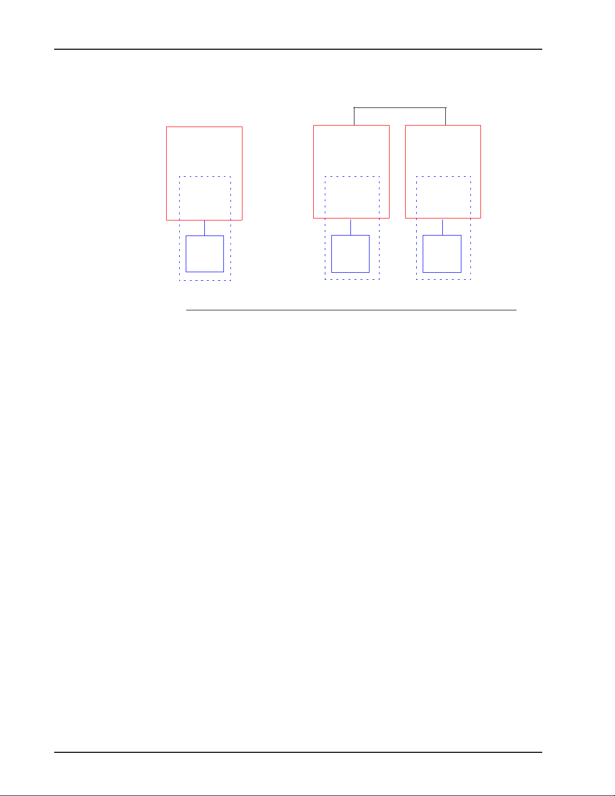
Single Media Processing Server 100 and Basic Media Processing Server 1000 Network
MPS
MPS1000 Network
Node A
MPS 1
ASE
VOS
TMS
MPS
Node B
MPS 2
ASE
VOS
TMS
Page 20 # P0602477 Ver: 3.1.11
Page 21
Hardware Overview
Typical system hardware includes a SPARC (Solaris) or Intel (Windows)
application/transaction processor and related computer components (such as hard
drive and RAM) and TMS hardware, including storage for speech and data files, a
telephone interface card, network interface cards, power supplies, and various voice
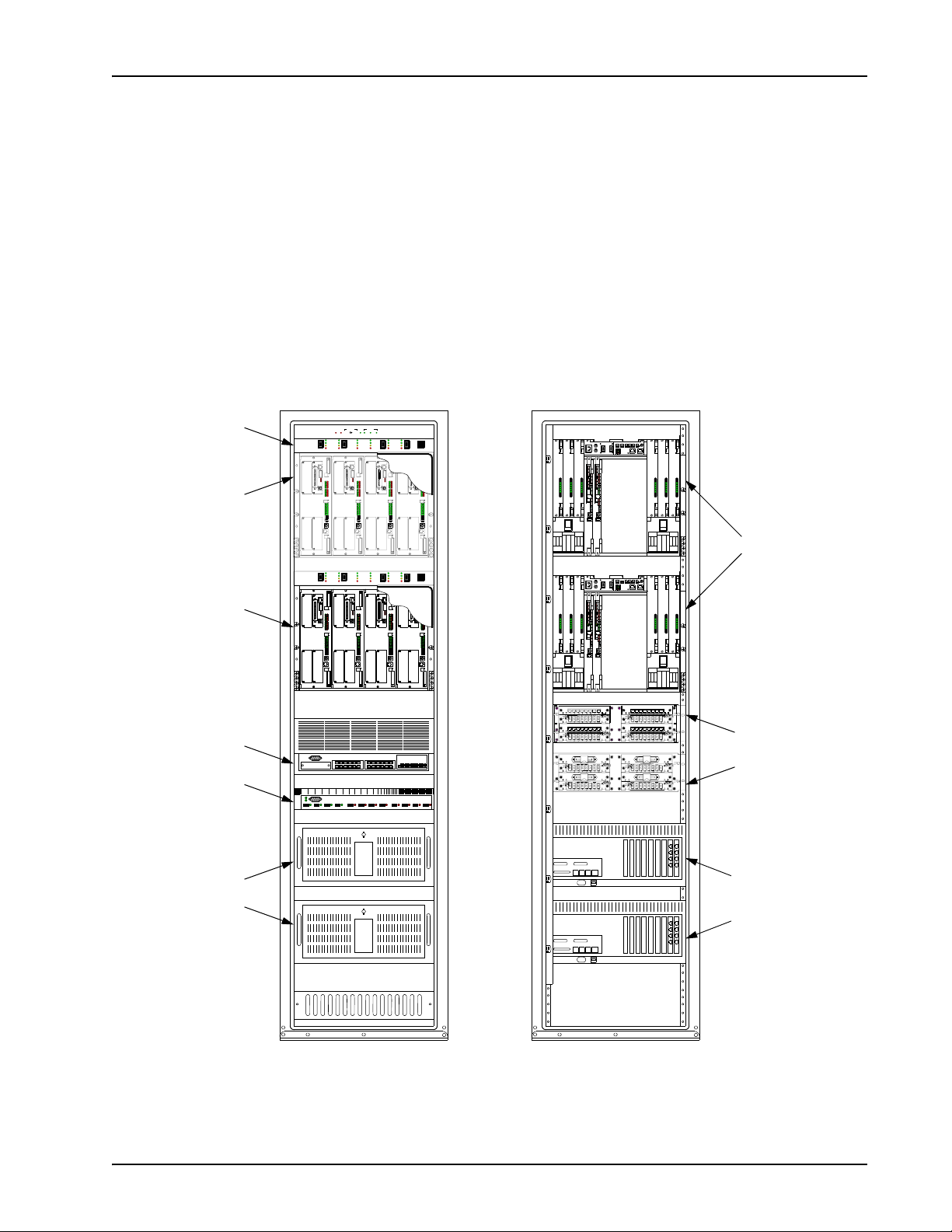
processing modules. The major hardware components that make up the MPS1000 are
shown in the following illustration (MPS100 information is contained in a separate
manual). Each of these is further dissected and discussed in the paragraphs that
follow. See the Avaya Media Processing Server Series System Operator’s Guide
regarding details on system monitoring and control and specific analysis of panel
switches and LEDs.
Avaya MPS Architectural Overview
Front Control
Panel (FCP)
Var iable
Resource
Chassis (VRCs),
populated with
Telephony Media
Server (TMS)
assemblies
Network
(Ethernet) Switch
Asynchronous
Transfer Mode
(ATM) Fiber
Optic Switch
Front View Rear View
OVER
FAULTS/
FAN SPEED
FAN SPEED
SYSTEM
TEMP
MAN HS
OK
MANUAL
AUTO
HIGH
TEMP
SPEED
CNTRL
LOWMEDHIGH
POWER ON
POWER ON
POWER ON
TEST
TEST
NORMAL
ON
OFF
SLOT
SLOT 3
SLOT 1
TEST
ON
OFF
SLOT
SLOT 3
SLOT 1
NORMAL
ON
MINOR ALARM
MINOR ALARM
OFF
MAJOR ALARM
MAJOR ALARM
2
1
5
L
L
C
O
C
O
M
P
M
P
SL1
SL1
2
2
S
L
S
L
EXT
EXT
COL
COL
M
P
M
P
3
3
S
L
S
L
SL4
SL4
HUB BHUB A
HUB BHUB A
T
T
E
X
E
X
SLOT 4
SLOT 4
SLOT 3
0
1
0
1
2
3
2
3
4
5
4
5
6
7
6
7
8
9
8
9
11
11
10
10
12
13
12
13
14
15
14
15
SLOT 2
SLOT 1
SLOT 2
AUDIOCONSOLE
AUDIOCONSOLE
POWER ON
POWER ON
TEST
NORMAL
NORMAL
ON
MINOR ALARM
MINOR ALARM
OFF
MAJOR ALARM
MAJOR ALARM
2
1
5
L
L
C
O
C
O
M
P
M
P
SL1
SL1
2
2
S
L
S
L
EXT
EXT
COL
COL
M
P
M
P
3
3
S
L
S
L
SL4
SL4
HUB BHUB A
HUB BHUB A
T
T
E
X
E
X
SLOT 4
SLOT 4
SLOT 3
0
1
0
1
2
3
2
3
4
5
4
5
6
7
6
7
8
9
8
9
11
11
10
10
12
13
12
13
14
15
14
15
SLOT 2
SLOT 1
SLOT 2
AUDIOCONSOLE
AUDIOCONSOLE
TEST
TEST
NORMAL
ON
ON
MINOR ALARM
OFF
OFF
MAJOR ALARM
6
6
RESET
3
4
L
L
C
O
C
O
M
P
M
P
SL1
SL1
2
2
S
L
S
L
EXT
EXT
COL
COL
M
P
M
P
3
3
S
L
S
L
SL4
SL4
HUB BHUB A
HUB BHUB A
T
T
E
X
E
X
SLOT 4
SLOT 3
SLOT 4
SLOT 3
0
1
0
1
2
3
2
3
4
5
4
5
6
7
6
7
8
9
8
9
11
11
10
10
12
13
12
13
14
15
14
SLOT 1
TEST
ON
OFF
SLOT 3
SLOT 1
15
SLOT 2
SLOT 1
SLOT 2
AUDIOCONSOLE
AUDIOCONSOLE
POWER ON
TEST
NORMAL
ON
MINOR ALARM
OFF
MAJOR ALARM
RESET
4
3
L
L
C
O
C
O
M
P
M
P
SL1
SL1
2
2
S
L
S
L
EXT
EXT
COL
COL
M
P
M
P
3
3
S
L
S
L
SL4
SL4
HUB BHUB A
HUB BHUB A
T
T
E
X
E
X
SLOT 4
SLOT 4
SLOT 3
0
1
0
1
2
3
2
3
4
5
4
5
6
7
6
7
8
9
8
9
11
11
10
10
12
13
12
13
14
15
14
15
SLOT 2
SLOT 1
SLOT 2
AUDIOCONSOLE
AUDIOCONSOLE
+3.3V
+3.3V
+3.3V
+5V
+5V
+5V
+12V
+12V
+12V
-12V
-12V
-12V
MIS-
MIS-
MIS-
MATCH
MATCH
MATCH
+3.3V
+3.3V
+3.3V
+5V
+5V
+5V
+12V
+12V
+12V
-12V
-12V
-12V
MIS-
MIS-
MIS-
MATCH
MATCH
MATCH
0
CHASSIS ID
0
CHASSIS ID
EXT CLK A
EXT CLK B
EXT CLK A
EXT CLK B
MC1 IN
MC1 OUT
ALARM
EXTERNAL SENSORS
MAJ M IN
CSL
NCCNOABCD
NCCNO
TEST
NIC
ENET-A
S5S6
ON
PWR ON
OFF
NORMAL
MIN ALARM
6
SLOT
5
MAJ ALARM
ENET-B
+3.3V
+3.3V
+3.3V
+5V
+5V
+5V
+12V
+12V
+12V
-12V
-12V
-12V
MIS-
MIS-
MIS-
MATCH
MATCH
MATCH
Rear of VRCs
MC1 IN
MC1 OUT
ALARM
EXTERNAL SENSORS
MAJ M IN
CSL
NCCNOABCD
NCCNO
TEST
NIC
ENET-A
S5S6
ON
PWR ON
OFF
NORMAL
MIN ALARM
6
SLOT
5
MAJ ALARM
ENET-B
+3.3V
+3.3V
+3.3V
+5V
+5V
+5V
+12V
+12V
+12V
-12V
-12V
-12V
MIS-
MIS-
MIS-
MATCH
MATCH
MATCH
TelCo Connector
Panels (TCCP)
Application
Processors
Rear of
Application
Processors
# P0602477 Ver: 3.1.11 Page 21
Page 22
Avaya Media Processing Server Series System Reference Manual
For detailed information on the physical, electrical, environmental, and interface
specifications of the Avaya Media Processing Server (MPS) Series, please refer the
MPS Specifications chapter in the Avaya MPS Hardware Installation and
Maintenance manual.
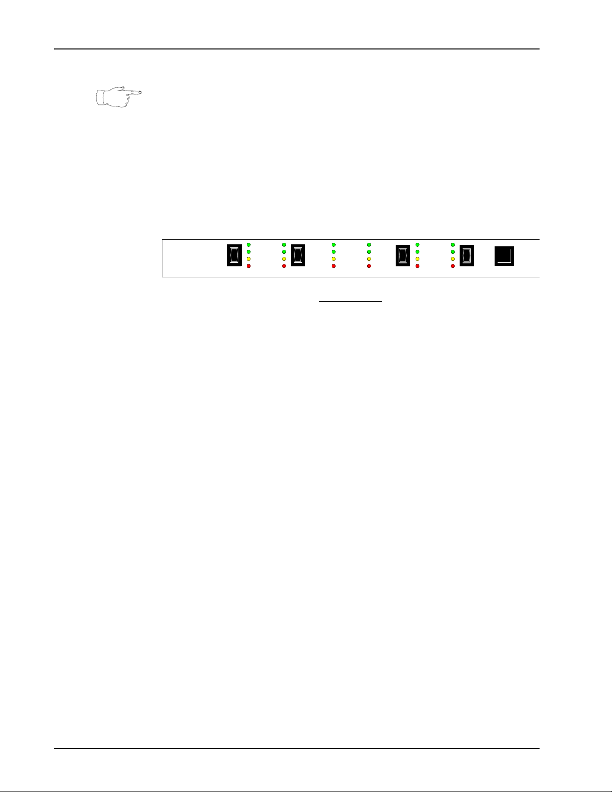
Front Control Panel (FCP)
One FCP is present for each VRC in the system. The FCP provides separate power
controls and status indicators for each TMS (by chassis slot).
SLOT
TEST
OFF
POWER ON
1
NORMAL
MINOR ALARM
MAJOR ALARM
ON
TEST
ON
OFF
2
POWER ON
NORMAL
MINOR ALARM
MAJOR ALARM
5
MINOR ALARM
MAJOR ALARM
3
POWER ON
NORMAL
TEST
ON
OFF
4
RESET
TEST
ON
OFF
6
FCP Front View
Variable Resource Chassis (VRC)
The VRC is a versatile chassis assembly that is used in several Avaya product lines.
The VRC has four front and two rear plug-in slots, and contains:
• Up to four TMS assemblies
• One or two application processor board(s) (rear; not present if rack mounted
application processor(s) are used)
• Two Network Interface Controllers (NICs) or one Hub-NIC
• Up to six power supplies, one for each populated slot
• Two available drive bays
Page 22 # P0602477 Ver: 3.1.11
Page 23
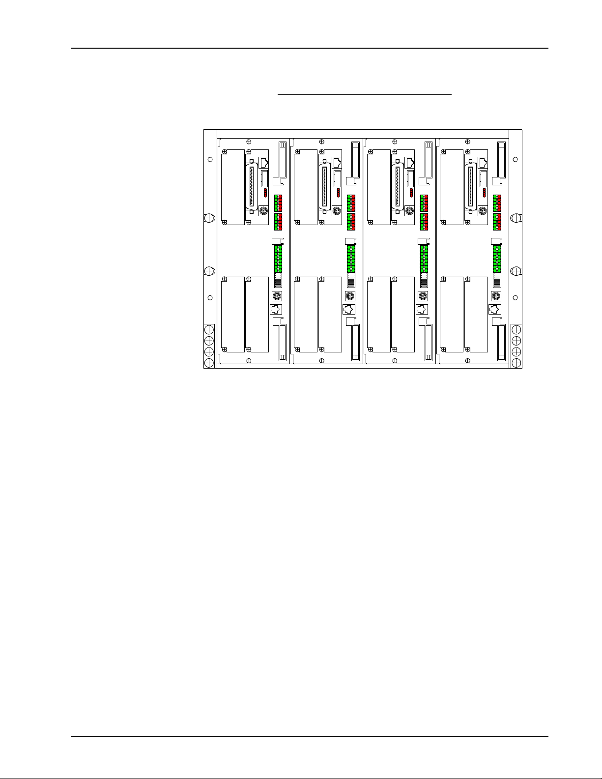
VRC Front View (Populated with Four TMS’)
Slot 1 Slot 2 Slot 3 Slot 4
Avaya MPS Architectural Overview
L
C
O
M
P
1
S
L
2
S
L
T
E
X
L
C
O
M
P
3
S
L
4
S
L
HUB B HUB A
T
E
X
SLOT 4
SLOT 3
SLOT 1
0
2
4
6
8
10
12
14
SLOT 2
SLOT 3
1
3
5
7
9
11
13
15
SLOT 1
SLOT 2
AUDIO CONS OLE
L
C
O
M
P
1
S
L
2
S
L
T
E
X
L
C
O
M
P
3
S
L
4
S
L
HUB B HUB A
T
E
X
SLOT 4
0
2
4
6
8
10
12
14
SLOT 3
1
3
5
7
9
11
13
15
SLOT 1
AUDIO CONS OLE
L
C
O
M
P
1
S
L
2
S
L
T
E
X
L
C
O
M
P
3
S
L
4
S
L
HUB B HUB A
T
E
X
SLOT 4
0
2
4
6
8
10
12
14
SLOT 2
SLOT 3
1
3
5
7
9
11
13
15
SLOT 1
AUDIO CONS OLE
L
C
O
M
P
1
S
L
2
S
L
T
E
X
L
C
O
M
P
3
S
L
4
S
L
HUB B HUB A
T
E
X
SLOT 4
0
1
2
3
4
5
6
7
8
9
11
10
13
12
14
15
SLOT 2
AUDIO CONS OLE
The VRC backplane is located midway between the front and rear of the chassis. The
backplane contains connectors for the modules that plug into each slot, front and back.
The backplane provides connections for:
• Inter-module signals
• Power from the power supplies to the module slots
• A Time Delay Multiplexing (TDM) bus for PCM (voice/audio)
communications between the TMS assemblies
• Clocking signals for the TDM bus
# P0602477 Ver: 3.1.11 Page 23
Page 24
Avaya Media Processing Server Series System Reference Manual
VRC Rear View
VRC Rear View
Power Supplies for slots
435 621
CHASSIS ID
+3.3V
+3.3V
MATCH
+3.3V
+5V
+5V
+12V
+12V
-12V
-12V
MIS-
MIS-
MATCH
MATCH
+5V
+12V
-12V
MIS-
VRC Rear Panel
EXT CLK A
0
EXT CLK B
MC1 IN
TEST
ON
OFF
6
SLOT
5
Alternate
Application
Processor
Location
(Slot 5)
MC1 OUT
ALARM
MAJ MIN
NC C NO
NIC
S5 S6
NCCNO
PWR ON
NORMAL
MIN ALARM
MAJ ALARM
EXTERNAL SENSORS
A
BCD
ENET-B
Power Supplies for slots
CSL
ENET-A
+3.3V
+3.3V
+5V
+5V
+12V
+12V
-12V
-12V
MIS-
MIS-
MATCH
MATCH
MATCH
+3.3V
+5V
+12V
-12V
MIS-
Hub-NIC
OR...
Drive Bay Drive BayNIC
(Primary)
(Logical Slot 7)
NIC
(Secondary)
(Logical Slot 8)
Application
Processor (Slot 6)
(If rack-mounted AP
is not used)
In multiple chassis and cabinet systems, some VRCs do not contain all the assemblies
listed above.
Power Supplies
Each slot in the VRC has a separate power supply dedicated to it. The power supplies
are identical and can be installed in any of the six locations for a slot that requires
power. The slot that each power supply is associated with is indicated on the decals on
the drive bay doors. There is no dedicated power supply for the NIC slot.
Page 24 # P0602477 Ver: 3.1.11
Page 25
+3.3V
+5V
+12V
-12V
MIS-
MATCH
Avaya MPS Architectural Overview
# P0602477 Ver: 3.1.11 Page 25
Page 26
Avaya Media Processing Server Series System Reference Manual
VRC Rear Panel
The rear panel of the VRC contains indicators, switches, and connectors for
maintenance, configuration, and connection to other system components. The power
switches for slots 5 and 6 are also located here, as well as the chassis ID wheel.
0
CHASSIS ID
EXT CLK A
EXT CLK B
MC1 IN
TEST
ON
OFF
6
SLOT
5
MC1 OUT
ALARM
MAJ MIN
NC C NO
NC C NO
NIC
S5 S6
PWR ON
NORMAL
MIN ALARM
MAJ ALARM
EXTERNAL SENSORS
A
BCD
ENET-B
CSL
ENET-A
Drive Bays
These bays contain the slots for and physical location of the system hard drives when
VRC-mounted application processors are used. Generally one drive is present per
processor, but additional drives may be added if system performance requires them.
Application Processor
In VRC-mounted configurations, the application processor is a “stripped down”
version of a Solaris or Windows computer: it contains the CPU, memory, and printed
circuit boards needed for both standard OS functions as well as basic MPS1000
transaction processing. One application processor is present per VRC in slot 6, but if
the VRC is populated with multiple TMS’ (which may in turn contain more than one
phone line interface card) and large numbers of spans, system performance may be
degraded and require the addition of another processor.
In typical rack-mounted configurations, there is one application processor per VRC,
and they are mounted at the bottom of the cabinet. This application processor is
similar in makeup to a typical Solaris or Windows computer. In either form, an
additional application processor may be added where instances of dual redundancy is
desired.
Page 26 # P0602477 Ver: 3.1.11
Page 27
Avaya MPS Architectural Overview
Network Interface Controller (NIC) or Hub-NIC
Each VRC in the system contains either two NICs (primary and secondary) or a single
Hub-NIC. The Hub-NIC plugs into the NIC slot in back of the VRC, and contains two
network hubs for the chassis Ethernet. It is generally used only in single chassis
systems. In multiple chassis systems, two NICs are used. In this case a midplane board
is installed over the backplane connector of the NIC slot, effectively splitting the slot
and providing separate connectors for each NIC. The two connectors on the midplane
board are logically assigned to slot 7 (primary) and slot 8 (secondary) for addressing.
The NICs have additional functionality such as system monitor capabilities, watchdog
timer, and alarm drivers, and can interface from the intra-chassis Pulse Code
Modulation (PCM) highways to a fiber optic Asynchronous Transfer Mode (ATM)
switching fabric. The NICs receive power from any installed power supply that is on.
NIC Hub-NIC
# P0602477 Ver: 3.1.11 Page 27
Page 28
Avaya Media Processing Server Series System Reference Manual
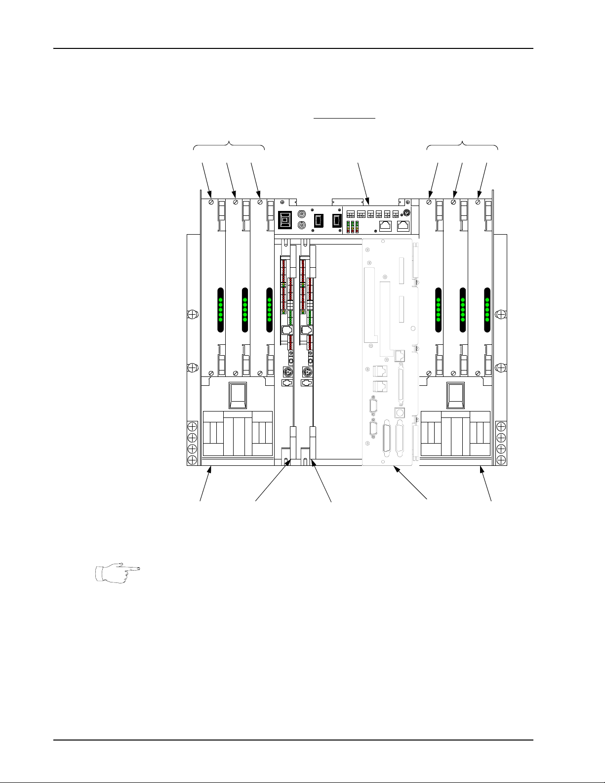
Telephony Media Server (TMS)
The TMS is the core functional module of the Avaya Media Processing Server (MPS)
Series system. It provides a versatile platform architecture for a broad range of
telephony functions with potential for future enhancement. The basic TMS assembly
consists of a motherboard and mounting plate containing front panel connectors and
indicators.
TMS Assembly Front View
01234567891011121314
SLOT 3
SLOT 4
HUB B HUB A
E
S
S
MPC
X
T
E
L
L
O
X
4
3
L
T
S
S
MPC
L
L
O
2
1
L
AUDIO CONSOLE
SLOT 1
SLOT 2
15
The TMS motherboard provides most essential functions for telephony and telephony
media management, including network and backplane bus interfaces, local memory,
digital signal processors, tone generators, local oscillators, and Phase-Lock Loop
(PLL) for Computer Telephony (CT) bus synchronization with other TMS’ and the
chassis. The motherboard contains a riser board that allows up to four additional
modules to be plugged in. The TMS motherboard also contains six Digital Signal
Processors (DSPs) which can be configured for communications protocols and to
provide resources.
Phone Line Interface
A TMS contains at least one phone line interface card, which can be a single Digital
Communications Controller (DCC) (see page 29) or up to three Analog Line Interface
(ALI) (see page 30) (a second DCC will be present if Voice over Internet Protocol
[VoIP] is installed). Though digital and analog line interfaces cannot be combined in
the same TMS, multiple TMS systems can contain any combination of digital and
analog lines in the VRC. Any line can be either incoming or outgoing, and all ports are
nonblocking (i.e., any port can be bridged to any other port). The TMS can also be
populated with a Multiple DSP Module (MDM) (see page 31), in one or more of the
remaining open slots. Although the motherboard has local digital signal processors,
the MDM provides additional resources for systems that require them.
Page 28 # P0602477 Ver: 3.1.11
Page 29

Avaya MPS Architectural Overview
A single TMS can support up to eight digital T1 (24 channels/span for a total of 192
lines) or E1 (30 channels/span for a total of 240 lines) spans by using an individual
DCC to connect to the Public Switched Telephone Network (PSTN). If some of the
lines are used exclusively for IVR resources, one or more spans may be dedicated.
Spans dedicated as such are connected directly in clear channel protocol. Supported
digital protocols include in-band T1/E1 and out-of-band SS7 and ISDN.
In addition a TMS can support up to 72 analog lines by using three ALI boards (24
lines per ALI). The standard analog interface supports common two-wire loop-start
circuits.
Information on configuration and application of phone line protocols and interfaces
can be found in the Ava ya Media Processing Server Series Telephony Reference
Manual.
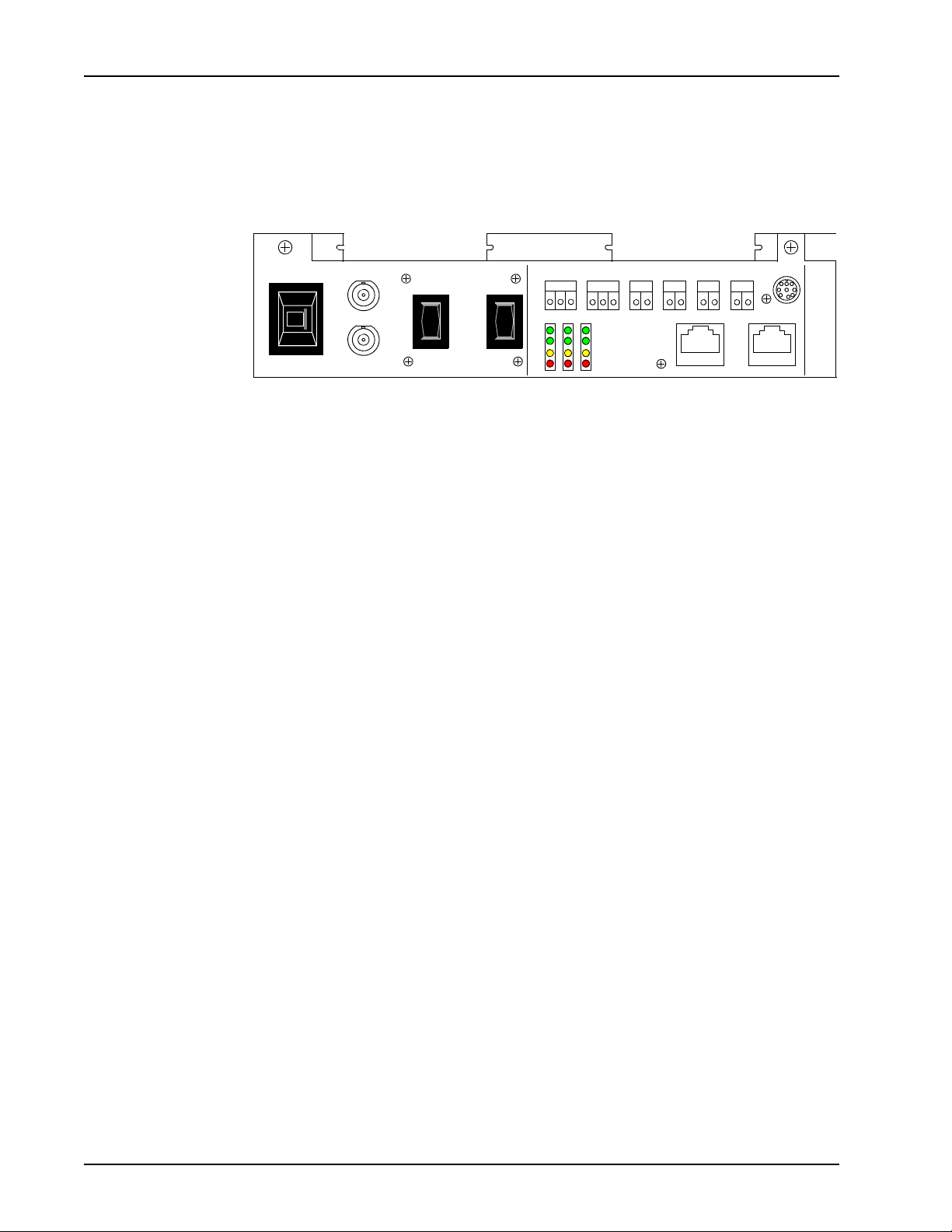
Digital Communications Controller (DCC)
The DCC provides the digital phone line interfaces for the system. It can be plugged
into any of the four slots of the TMS. The DCC is dedicated for either a T1 or E1
system, and connects to the PSTN via an RJ48M connector (up to eight spans).
The DCC is also capable of interfacing with a telephony network using VoIP. A
DCC-VoIP has no telephony connector on the front panel. Only one DCC is typically
installed in the TMS, unless the system is also using VoIP, in which case the
DCC-VoIP will also be installed. The DCC cannot be combined with an ALI in the
same TMS.
A serial console connector is provided for diagnostic purposes and for verifying and
configuring the boot ROM (see Verifying/Modifying Boot ROM Settings on page 252
for details). Other connectors and indicators are provided on the DCC front panel but
are reserved for future enhancement.
DCC Front View
Console
Connector
(Reserved for future enhancement)
RJ48M
Connector
# P0602477 Ver: 3.1.11 Page 29
Page 30

Avaya Media Processing Server Series System Reference Manual
Analog Line Interface (ALI)
The ALI provides a phone line interface to the system for up to 24 analog phone lines.
It connects to the PSTN via an RJ21X connector on the front panel. The standard
analog interface supports common two-wire loop-start circuits. There are no other
connectors or indicators on the front of the ALI.
Up to four ALIs can be installed in a TMS, although three is typical since one of the
four TMS slots is usually occupied by an MDM. ALIs cannot be combined with a
DCC in the same TMS.
ALI Front View
RJ21X
Connector
Page 30 # P0602477 Ver: 3.1.11
Page 31

Avaya MPS Architectural Overview
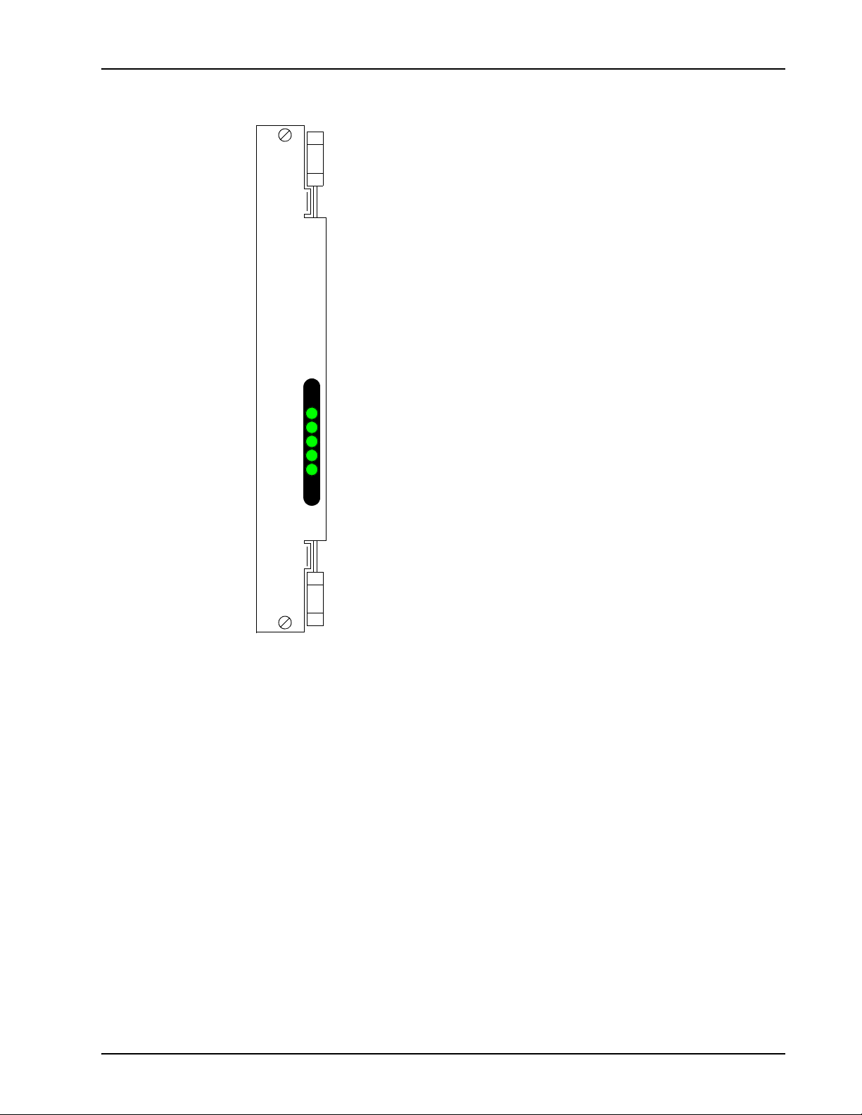
Multiple DSP Module (MDM)
A resource must be available on the system for an application to use it. If the resident
DSPs are fully allocated to resources or protocols, capacity for more resources can be
added by installing a Multiple DSP Module (MDM) in an open TMS slot and loading
the image definitions for the resources required. These resources are in addition to the
MPS resource itself. Examples of TMS supported resources are:
• Player (ply) - Vocabularies or audio data can be played from local memory
on the TMS motherboard.
• DTMF Receiver (dtmf) and Call Progress Detection (cpd) - Phone line
events such as touch-tone entry, hook-flash, dial tone, busy signals, etc. can
be detected.
• Tone Generator (tgen) - In lieu of playing tones as vocabularies, DTMF
and other tones can be generated.
• R1 Transmit (r1tx), R1 Receive (r1rx), and R2 (r2) - Tone generators
and detectors to support R1 and R2 protocols.
The MDM contains 12 DSPs for configuration of additional resources. There are no
indicators or connectors on the front panel of the MDM. The only visible indication
that an MDM is installed in a TMS slot (versus a blank), is the presence of bend tabs
near the center of the front bracket that secure it to the MDM circuit board.
MDM Front View
Configuration of resources and protocols is covered in Base System Configuration on
page 64.
# P0602477 Ver: 3.1.11 Page 31
Page 32

Avaya Media Processing Server Series System Reference Manual
System LAN Interface
The TMS interfaces with the system Local Area Network (LAN) via Ethernets using
TCP/IP. The chassis Ethernet is connected via the VRC backplane to separate hubs on
the chassis NIC or Hub-NIC (see VRC Rear View on page 24). If there is a failure on
the master Ethernet (controlled by the first NIC), the secondary NIC takes control of
all Ethernet A, system clocking, and ATM functions. The switchover is virtually
instantaneous and the inherent error correction of TCP/IP prevents loss of data.
The redundant Ethernet is only for backup of the primary Ethernet. Ethernet A
is the ONLY Ethernet supported between the chassis and the Application
Processor. There is no support for dual redundant Ethernet.
Field Programmable Gate Arrays (FPGA) and the Boot ROM
The TMS and the modules that plug into it (i.e., DCC, MDM, and ALI) contain
FPGAs. An FPGA is a generic microchip that has no inherent functionality. It
contains arrays of generic logic elements (e.g., gates) that are software configurable.
The software that configures the FPGA is called an image, and the image typically
commands the FPGA to assume the functionality of a designed logic circuit. A
hardware architecture based on FPGAs is very powerful and flexible because:
• A greater degree of complex logic functionality can be achieved in a
relatively smaller board space with fewer circuit components than if dedicated
circuit components and hard board wiring were used. This also provides
greater circuit reliability.
• Functionality can be enhanced without hardware redesign or even removal
and replacement. Upgrades can be done in the field by loading a new image
definition.
FPGAs are dynamic devices in that they do not retain their image definition when
power is removed. The image definition for each device is loaded from an image
definition file (*.idf) during the system boot sequence. The TMS contains a boot
ROM that statically stores the names of the .idf files for the devices contained on its
motherboard and the modules that are plugged in.
Whenever a new system is installed, has components added or replaced, or the system
is upgraded, the boot ROM should be verified and, if necessary, modified by Certified
Avaya Support Personnel. Details concerning boot ROM verification can be found at
Verifying/Modifying Boot ROM Settings on page 252.
Page 32 # P0602477 Ver: 3.1.11
Page 33

Avaya MPS Architectural Overview
TelCo Connector Panel (TCCP)
The TCCP provides a built-in platform for connecting to the Public Switched
Telephone Network (PSTN) and for conveniently breaking out and looping-back
spans for monitoring or off-line testing. One TCCP can support up to four TMSs and
can be configured with RJ48M or RJ48C connectors for each TMS.
TCCP with RJ48M Interfaces
TCCP with RJ48C Interfaces
TCCP Rear View
J2 (Connects
to TMS 2)
J4 (Connects
to TMS 4)
J3 (Connects
to TMS 1)
J1 (Connects
to TMS 3)
The TCCP is connected to each TMS from the corresponding connector on the TCCP
back panel by a direct feed RJ48M cable. In TCCP equipped systems, PSTN
connections are made at the TCCP using the RJ48M or RJ48C connectors on the front
of the panel. A pair of bantam jacks (SND and RCV) is provided for each span
connected to the TCCP. The bantam jacks are resistor isolated and can be used for
monitoring only. The bantam jacks cannot be used to create span loop-back
connections. Loop-back connections for testing purposes can be made between TMSs
or spans using special crossover cables. For details, see the Avaya Media Processing
Server Series 1000 Transition Guide.
# P0602477 Ver: 3.1.11 Page 33
Page 34

Avaya Media Processing Server Series System Reference Manual
Software Overview
The following illustration shows the functional arrangement of the ASE and VOS
processes for MPS release 1.x. Though many of the processes are similar to those of
release 5.x, there are several new and revised processes, all of which are described in
the paragraphs that follow.
ASE
Processes
PPro
App.
VENGINE
ASE/VOS Integration Layer
VOS Process Group
(1 per TMS)
SRP
CFG
PPro
App.
VENGINE
VMST VSUPD
VAM P
COMMGR
protocol
CCMA
CCM
host
PPro
App.
VENGINE
Common Processes
(1 each per node)
CONFIGD
VSTAT
CONOUT
ALARMD
To h os t
VSH
To system
console
To alarm
viewer
MMF
TCAD
VSH
PMGR
TMS Common
Processes
(1 per node)
CONSOLED
VSH
To TRIPs of
VMM
TRIP NCD
other VOS
process groups
(if present)
VMem
TMS
LRM,
ADSM,
SIM
Master Slave
NIC Pairs
Page 34 # P0602477 Ver: 3.1.11
Page 35

Avaya MPS Architectural Overview
Software Environment
The MPS software components are categorized into two process groups: VOS (Voice
Operating Software) and ASE (Application Services Environment).
The VOS software process group comprises the main system software required to run
the MPS system. The ASE software process group contains the software required to
develop and execute applications.
VOS and ASE software processes have been designed to operate in an open systems
Solaris or Windows environment. All speech, telephony, and communications
functions run under Solaris or Windows, and require no additional device drivers.
VOS uses the standard Solaris or Windows file system for managing all speech/fax
data. A set of GUI tools provides for application development and system
management.
Some VOS and ASE software processes are common to all MPS components defined
on a specific host node; these are located in the GEN subcomponent of the common
component on that node (and defined in the file
$MPSHOME/common/etc/gen.cfg). Other VOS processes are unique to each
defined MPS component, and are part of the VOS subcomponent of the MPS
component (and defined in $MPSHOME/mpsN/etc/vos.cfg). The NCD process,
on the other hand, is part of the VOS subcomponent of the tmscomm component
(and defined in $MPSHOME/tmscommN/etc/vos.cfg). This TMS-specific
process requires one instance per node; other common processes also require that only
a single instance of the process execute on a node. Processes that are unique to each
component require an instance of each process be executed for each MPS component
defined on the node. When uncommented in their respective gen.cfg or
vos.cfg files, these processes are started by the Startup and Recovery Process
(SRP). (For a more comprehensive discussion about SRP, see SRP (Startup and
Recovery Process) on page 70.)
Individual applications are executed by means of a separate instance of the ASE
process VENGINE for each instance of the application’s execution. There are three
major types of applications:
• Call processing applications are assigned to physical phone lines. A separate
instance of both the application and VENGINE process is required for each
physical phone line to which the application is assigned.
• Administrative applications perform system maintenance functions and
support the call processing applications. They are not assigned with physical
phone lines. However, they also require a separate instance of VENGINE for
each instance of the application.
Applications can communicate with each other by means of shared memory or
message passing.
# P0602477 Ver: 3.1.11 Page 35
Page 36

Avaya Media Processing Server Series System Reference Manual
ASE Processes
The Application Services Environment (ASE) process group is comprised of software
required to develop and execute applications. ASE processes include:
Process Description
VENGINE The application execution process. One VENGINE process is
required for each MPS application (call processing, web based,
and administrative).
VMST VENGINE Message Server - Extended. Manages MPS
messages related to VENGINE applications. This process also
can be used to bridge messages in a multi-MPS environment.
VSUPD Collects application-specific statistics (as opposed to system
statistics).
• VMST, and VSUPD are node-specific processes and require only one
occurrence of the process for each host node regardless of the number of
components defined on the node.
• VENGINE is an application-specific process. One occurrence of VENGINE
must execute for each application assigned to an MPS line.
VENGINE
VENGINE is the application-specific ASE software process. It is responsible for the
execution of each occurrence of an application that is assigned to an MPS. One
VENGINE process is required to execute for each occurrence of a call processing,
web based, or administrative application. Administrative applications are not
associated with physical phone lines and perform system maintenance operations and
support call processing applications.
Additionally, VENGINE is used to execute all or part of an application while it is
under development. It can run all or part of the application so that the logic paths and
application functions may be tested.
VENGINE is located in $MPSHOME/PERIase/bin on Solaris systems and
%MPSHOME%\bin on Windows systems, and can be initiated from the command
line or by starting an application with the PeriView Assign/(Re)Start Lines tool (see
the PeriView Reference Manual for more information on the latter). Applications that
require ASE processes are located in the $MPSHOME/mpsN/apps directory. For
additional information about these applications, see The MPSHOME/mpsN/apps
Directory on page 140. VENGINE makes connections to both these applications and
VMST. For additional information on VENGINE, see the PeriProducer User’s
Guide.
VMST
VMST (VENGINE Message Server - Extended) is an ASE software process that
Page 36 # P0602477 Ver: 3.1.11
Page 37

Avaya MPS Architectural Overview
performs message server functions for VENGINE. It funnels VOS messages that have
been translated by VAMP to VENGINE processes and service daemons. VMST
interprets and supports all pre-existing VMS options, allowing scripts incorporating
them to continue functioning under the present release without any modifications.
The advent of the TMS brings about an increase in the number of lines supportable on
a single platform, as well as an increase in potential message traffic. In order to handle
the increase in addressable lines, this modified version of VMS was created
(previously, VMS addressing was limited to a one-to-one correspondence of VMS to
CPS/VPS). Though VMST can still act on behalf of a single MPS, VMST can also
address the new paradigm by supporting many real or virtual MPS’ in a single process
(the VMST process assumes the functions of one or more VMS’ running on the same
node). In addition, VMST:
• eliminates traffic between VMS’, since all messages are now passed between
threads inside the VMST process.
• supports interapplication communications between the MPS systems (the
MPS system to which an application directs a message must be directly
connected to the MPS running the application). Inter-VMST traffic is
supported as described in Interapplication/Host Service Daemon Data
Exchange on page 215.
• supports automatic detection of lost TCP/IP connections (pinging)
The VMST process is located in $MPSHOME/PERIase/bin (Solaris) or
%MPSHOME%\bin (Windows). When used with a single MPS, VMST is started by
SRP through the $MPSHOME/mpsN/etc/ase.cfg file. When used with multiple
MPS’ (whether real or virtual), it is started through the
$MPSHOME/common/etc/gen.cfg file. In addition to VENGINE and VAMP,
VMST makes connections to the VSUPD processes
VMST is aliased as vms in its SRP startup files, but should not be confused with
previous (“non-extended”) versions of VMS.
# P0602477 Ver: 3.1.11 Page 37
Page 38

Avaya Media Processing Server Series System Reference Manual
VSUPD
VSUPD is the ASE software process that is responsible for collecting applicationspecific statistics. VSUPD is a node-specific process, thus one instance of this process
is required for each node regardless of the number of MPS components assigned to the
node.
This process need not be run unless application statistics have to be collected and
reported.
Each node collects statistics at 15-minute intervals for all applications executing on all
MPS’ on the node and stores them in the ASEHOME/stats directory. On systems
with remote nodes, statistics for the four previous 15-minute periods are collected
hourly from all other nodes by the one designated for MPS network statistical
collection and reporting and transferred to that node’s ASEHOME/stats directory.
VSUPD supports an optional command line argument -w <secs>, which specifies
the maximum amount of time to wait for phone line responses.
PeriReporter, in conjunction with the individual call processing applications, is used
to define the statistical events to be collected and to create and generate reports. For
information about PeriReporter, see the PeriReporter User’s Guide.
VSUPD is started by SRP through the
located in $MPSHOME/PERIase/bin on Solaris systems and %MPSHOME%\bin
on Windows systems. It makes its connections to VMST.
System statistics are collected by the VSTAT process on a per-MPS basis. For
information about the VSTAT process, see VSTAT on page 50.
$MPSHOME/common/etc/gen.cfg file and
Page 38 # P0602477 Ver: 3.1.11
Page 39

Avaya MPS Architectural Overview
ASE/VOS Integration Layer
This layer is used to convert and translate messages from the applications to the VOS
processes. For PeriProducer applications, this layer communicates with the ASE
processes, which in turn communicate with the applications themselves. The Vengine
Application Management Process (VAMP) is an interface between the Application
Services Environment (ASE) and the Voice Operating Software (VOS).
The VAMP services application requests:
• Consolidate information (lines, resources, etc.) for applications
• Consolidate information for commands issued by applications
• Control line bridging based on Call Progress Detection information
• Process resource control commands which may be directed to different
resource providers and have different formats
VOS Processes
The Voice Operating Software (VOS) process group is comprised of the main system
software required to run the MPS system. VOS processes can be common (only one
instance required per node) or MPS-specific (one instance required per MPS
component). This software group consist of the following independently running
processes:
Process Description
ALARMD (Alarm Daemon) Collects alarm messages, writes them to
the alarm log, and forwards them to any
running alarm viewers.
CCM (Call Control Manager) The primary interface between VAMP
and the VOS services. Provides request
synchronization and resource
management.
COMMGR (Communications Manager) Manages external host communications.
CONFIGD (Configuration Daemon) System wide configuration process.
CONOUT (Console Output Process) Relays output from VOS processes to
the system console.
CONSOLED (Console Daemon) Takes messages that would normally
appear on the system console and
displays them in the alarm viewers.
(Solaris only.)
NCD (Network Interface Controller
Daemon)
Controls interconnections between
multiple TMS platforms attached to the
NIC card.
nriod Daemon responsible for remote
input/output.
# P0602477 Ver: 3.1.11 Page 39
Page 40

Avaya Media Processing Server Series System Reference Manual
Process Description
PMGR (Pool Manager) Provides resource management,
including resource allocation, resource
deallocation, and keeping track of
resource allocation statistics.
rpc.riod Daemon responsible for remote
input/output (Solaris backward
compatibility only).
TCAD (TMS Configuration & Alarm
Daemon)
TRIP (TMS Routing Interface Process) Acts as a router between the VOS and
VMM (Voice Memory Manager) Provides media management services
VSTAT (VPS Statistics Manager) Provides system (as opposed to
ALARMD
ALARMD resides in the GEN subcomponent of the common component. It is
responsible for collecting alarm messages, writing them to the alarm log, and
forwarding alarms to the MPS alarm viewers. The alarm logs are located in the
directory $MPSHOME/common/log in the format
alarm.<component_type>.<component_#>.log, with backup files being
appended with the .bak extension.
To avoid problems with memory exhaustion and the ALARMD daemon growing out
of bounds, alarms can be suppressed from being logged to disk or being transmitted to
the viewers (see Alarm Filtering on page 203). The daemon accepts commands either
dynamically during run-time or statically from its configuration file during startup.
Provides loading, configuration, and
alarm functions for TMS.
TMS.
for the VOS.
application) statistics consolidation and
reporting.
ALARMD associations:
• Connections: All processes which generate alarms
• Location: $MPSHOME/bin or %MPSHOME%\bin
• Configuration File: $MPSHOME/common/etc/alarmd.cfg
• SRP Startup File: $MPSHOME/common/etc/gen.cfg
The alarmd.cfg file only exists on systems where alarm filtering is instituted at
startup (see The alarmd.cfg and alarmf.cfg Files on page 99).
The alarm command may be used to display the text of alarms, that are broadcast
from ALARMD, in a command or VSH window. The PeriView Alarm Viewer is the
GUI tool that may be used to select and display this same alarm information.
Page 40 # P0602477 Ver: 3.1.11
Page 41

Avaya MPS Architectural Overview
See the PeriView Reference Manual for additional information about the Alarm
Viewer and the alarm information that may be obtained with this tool.
You can configure ALARMD to display the year in the timestamps that are added to
entries written to the alarm log files (such as info, warming, alarm, and app). By
default, the year is not displayed in the timestamp.
The optimum way to enable the display of the year in the timestamps of alarm log
entries is to start ALARMD with the command line option -y. This can be done by
modifying the COMMAND LINE field for ALARMD in the
$MPSHOME/common/etc/gen.cfg configuration file to include the -y
command line option. The entry for ALARMD in that file would appear as follows
(note that the quotation marks are required):
alarmd - - 1 0 “alarmd -y”
An alternate method of enabling the display of the year in the timestamps of alarm log
file entries is to add either of the following lines to the ALARMD configuration file
$MPSHOME/common/etc/alarmd.cfg:
alarmd showyear on
alarmd showyear 1
Displaying the year in the timestamps of alarm log file entries can be enabled or
disabled after ALARMD starts by using VSH to issue the showyear console option
with an appropriate argument to ALARMD.
For example, to enable the display of the year in the timestamps of alarm log file
entries, issue either of the following commands at a vsh prompt:
alarmd showyear on
alarmd showyear 1
To disable the display of the year in timestamps of alarm log file entries, issue either
of the following commands at a vsh prompt:
alarmd showyear off
alarmd showyear 0
If you want to display the year in the timestamps of alarm log file entries, Avaya
recommends using the -y command line option in
$MPSHOME/common/etc.gen.cfg to ensure that the year appears in the
timestamp of every alarm written to the log file. If you use either of the other options
described above, alarms generated early in the bootup sequence may not display the
year in their timestamps
For additional information about the alarm facility, see System Utilities and
Software on page 51. alarm is located in $MPSHOME/bin on Solaris systems or
%MPSHOME%\bin on Windows systems.
# P0602477 Ver: 3.1.11 Page 41
Page 42

Avaya Media Processing Server Series System Reference Manual
CCM
CCM resides in the VOS subcomponent of the MPS component. Two CCM processes
will exist in the VOS subcomponent: CCM and CCMA. CCM manages and controls
phone lines and all resources required for interacting with the phone line (caller).
CCMA provides administrative services only, and does not provide phone line related
services (i.e., outdial, call transfer, etc.). Configuration is accomplished in one of two
ways: process wide or line/application specific. Process wide configuration is setup in
ccm_phoneline.cfg (for CCM) or ccm_admin.cfg (for CCMA).
Line/application specific configuration is achieved by the application by setting up its
required configuration when it binds with CCM/CCMA.
The CCM process is primarily responsible for:
• managing the phone line state dynamic
• allocating and deallocating internal and external resources, as well as
administering the former
• command queue management and synchronization
• element name parsing for play, record and delete requests
• servicing audio play and record requests
• data input management (touch-tones, user edit sequences, etc)
• third party call control (conference management)
• maintaining call statistics
The CCMA process is primarily responsible for:
• command queue management and synchronization
• element name parsing for delete and element conversion requests
• MMF event reporting
• maintaining statistics
The VSH interface provides the ability to send commands to CCM. For a list of these
commands, see the CCM Commands section in the Avaya Media Processing Server
Series Command Reference Manual.
CCM associations:
• Connections: VAMP, NCD, TRIP, TCAD, VMM, PMGR
• Location: $MPSHOME/bin or %MPSHOME%\bin
• Configuration Files:
• For CCM: $MPSHOME/mpsN/etc/ccm_phoneline.cfg
• For CCMA: $MPSHOME/mpsN/etc/ccm_admin.cfg
• SRP Startup File: $MPSHOME/mpsN/etc/vos.cfg
Page 42 # P0602477 Ver: 3.1.11
Page 43

Avaya MPS Architectural Overview
COMMGR
COMMGR resides in the VOS subcomponent of the MPS component and provides
transaction processing services for the VOS. It enables application programs to
communicate with external host computers using a variety of protocols. Though
functionally equivalent to pre-existing versions, the release 1.0 COMMGR no longer
requires that Virtual Terminals (VTs) be mapped to phone lines.
The commgr.cfg file defines the configuration parameters required to communicate
with most external hosts. For more information, see The commgr.cfg File on page
144.
Host communications functions and protocols are documented in the Avaya Media
Processing Server Series Communications Reference Manual.
COMMGR associations:
• Connections: Protocol server processes
• Location: $MPSHOME/bin or %MPSHOME%\bin
• Configuration File: $MPSHOME/mpsN/etc/commgr.cfg
• SRP Startup File: $MPSHOME/mpsN/etc/vos.cfg
!
CONFIGD
CONFIGD is the system wide configuration process. It reads configuration files on
behalf of a process and sends this configuration information to the process.
Online reconfiguration must only take place when the system is idle (no applications
are attached). Unexpected behavior will result if the system is not idle during an
online reconfiguration.
CONFIGD associations:
• Connections: All VOS processes
• Location: $MPSHOME/bin or %MPSHOME%\bin
• Configuration File: Not applicable
• SRP Startup File: $MPSHOME/common/etc/gen.cfg
# P0602477 Ver: 3.1.11 Page 43
Page 44

Avaya Media Processing Server Series System Reference Manual
CONOUT
CONOUT is the VOS process that is responsible for providing output to the system
console. On Windows this provides output to the window in which SRP is started. It
receives display data from the VOS processes and routes it to the system console.
CONOUT associations:
• Connections: Any VOS process sending info to the system console
• Location: $MPSHOME/bin or %MPSHOME%\bin
• Configuration File: Not applicable
• SRP Startup File: $MPSHOME/common/etc/gen.cfg
CONSOLED
CONSOLED takes messages that would normally appear on the system console and
displays them in an alarm viewer. These messages include:
• system messages
• Zero Administration for Prompts (ZAP) synchronization status alarms
System messages can be generated by the MPS system or the operating system itself.
CONSOLED associations:
• Connections: Any process sending info to the system console
• Location: $MPSHOME/bin
• Configuration File: Not applicable
• SRP Startup File: $MPSHOME/common/etc/gen.cfg
Page 44 # P0602477 Ver: 3.1.11
Page 45

Avaya MPS Architectural Overview
NCD
NCD is comprised of three distinct logical entities: bridge control; Phase-Lock Loop
(PLL) control; and a VSH interface to the NIC board itself. As part of the tmscomm
component process group, one instance of NCD exists on a node containing TMS’. It
interfaces with the TRIP and CCM processes in each VOS on the node, and with
embedded processes running on the two chassis NICs (i.e., master, slave).
The NCD Bridge Control Process (NCD BCP) provides a common interface to
support bridging between Resource Sets (RSETs) on or between TMS’. NCD BCP
orchestrates the setup and teardown of the various bridging configurations supported
by the TMS and NIC architecture. NCD BCP also has the ability to construct bridges
between a pair of TMS’ where the connections are physically hardwired (on a
Hub-NIC card), or locked on a Time Space Switch (TSS) on the NIC.
The NCD PLL process provides configuration and control of the timing and clock
sources on and between TMS’ in a common chassis. NCD PLL is primarily used in
small systems that do not have a NIC to provide these functions.
The NCD VSH interface provides the ability to send simple configuration commands
to the NIC as well as query the current configuration. For a list of these commands,
see the NCD Commands section in the Avaya Media Processing Server Series
Command Reference Manual.
NCD associations:
• Connections: TRIP (local and remote)
• Location: $MPSHOME/bin or %MPSHOME%\bin
• Configuration File: $MPSHOME/common/etc/tms/tms.cfg
• SRP Startup File: $MPSHOME/tmscommN/etc/vos.cfg
nriod
The nriod file provides information and access to MPS files for remote PeriView
processes in both the Solaris and Windows environments. nriod is a system daemon
and, as such, only one instance of this process is required for each node.
nriod associations:
• Connections: Any process communicating with the PeriView Task Scheduler
• Location: $MPSHOME/bin or %MPSHOME%\bin
• Configuration File: Not applicable
• SRP Startup File: $MPSHOME/common/etc/gen.cfg
# P0602477 Ver: 3.1.11 Page 45
Page 46

Avaya Media Processing Server Series System Reference Manual
PMGR
PMGR provides pooled resource management of all resources from Resource
Provider (RP) processes running on the local node. An example of an RP is the CCM
process, which provides lines as resources. An RP registers its resources with PMGR
upon initialization. A registered resource can also be pooled applications (used for call
handoff, for instance). As applications request resources, PMGR allocates the
resources, keeps track of applications and their resources, maintains statistics, and
deallocates resources as necessary.
If PMGR cannot allocate a resource locally, it forwards the request to a remote
instance of PMGR; the specific instance is determined through round-robin
availability. If there are no remote PMGRs available, the request fails. If PMGR dies,
it releases all resources that have been allocated; if an RP dies, it must reconnect to
PMGR to reregister its resources; if an application dies, allocated resources remain
with it: after the application restarts, it queries PMGR for a list of resources currently
allocated to the application; it may then use these resources or free them if no longer
needed.
PMGR associations:
• Connections: Any process that provides resources (RP), applications
• Location: $MPSHOME/bin or %MPSHOME%\bin
• Configuration File: $MPSHOME/common/etc/pmgr.cfg
• SRP Startup File: $MPSHOME/common/etc/gen.cfg
The VSH interface also provides the ability to send commands to PMGR. For a list of
these commands, see the PMGR Commands section in the Avaya Media Processing
Server Series Command Reference Manual.
rpc.riod
The rpc.riod file provides information and access to MPS files for remote
PeriView processes in the SPARC/Solaris environment. rpc.riod is a system
daemon and, as such, only one instance of this process is required for each node.
This file is maintained for backward compatibility for systems running pre-5.4
software. nriod on page 45 is now included with the system to provide Solaris and
Windows functionality.
rpc.riod associations:
• Connections: Any process communicating with the PeriView Task Scheduler
• Location: $MPSHOME/bin
• Configuration File: Not applicable
• SRP Startup File: $MPSHOME/common/etc/gen.cfg
TCAD
TCAD resides in the VOS subcomponent of the MPS component. It provides both
Page 46 # P0602477 Ver: 3.1.11
Page 47

Avaya MPS Architectural Overview
alarm and diagnostic services for the TMS hardware and loading and configuration
services for the VOS. This includes:
• loading and configuration of all TMS devices
• a listing of TMS internal resources to the VOS
• alarm generation on behalf of TMS devices by translating TMS alarm code to
the correct alarm format used by the alarm daemon (see ALARMD on page
40).
• diagnostics (System Performance Integrity Tests) which provide information
about any device in the TMS. TCAD allows other processes to request
information about any device (i.e., request telephony span status).
• logging capabilities for the hardware
• statistics and internal information about TMS devices
TCAD communicates with the TMS via TRIP. This includes sending loading and
configuration messages through the Load Resource Management (LRM) port and
sending and receiving alarm messages via the Alarm, Diagnostic, and Statistics
Management (ADSM) port.
User interface with TCAD is via a VSH command line, which provides the ability to
send commands to TCAD.
TCAD associations:
• Connections: TRIP, ALARMD, VMM, PMGR, and configuration files
• Location: $MPSHOME/bin or %MPSHOME%\bin
• Configuration File: $MPSHOME/mpsN/etc/tcad.cfg
• SRP Startup File: $MPSHOME/mpsN/etc/vos.cfg
# P0602477 Ver: 3.1.11 Page 47
Page 48

Avaya Media Processing Server Series System Reference Manual
TRIP
TRIP resides in the VOS subcomponent of the MPS component. It is responsible for
routing messages between the front end (VOS) and back end (TMS) over the TCP/IP
connection. TRIP communicates directly with the LRM, ADSM, and Call SIMulator
(SIM) ports of the TMS. TRIP is also responsible for providing the IP and port
number of the TMS connected to a VOS. The calling process must identify the
particular port on the TMS that it is interested in.
The VSH interface provides the ability to send commands to TRIP.
TRIP associations:
• Connections: CCM, VMM, TCAD, NCD, and the LRM, ADSM, and SIM
ports of the TMS
• Location: $MPSHOME/bin or %MPSHOME%\bin
• Configuration File: $MPSHOME/mpsN/etc/trip.cfg
• SRP Startup File: $MPSHOME/mpsN/etc/vos.cfg
Page 48 # P0602477 Ver: 3.1.11
Page 49

Avaya MPS Architectural Overview
VMM
VMM resides in the VOS subcomponent of the MPS component and provides media
management services for the VOS. When VMM starts it connects to TCAD, TRIP and
the VMEM port of the TMS. Once VMM detects that TCAD has configured the TMS,
VMM loads the Voice Data Memory (VDM).
The startup time for VMM is minimal and does not delay speak/record requests unless
the system is under heavy load. In the case of a record request under heavy load, the
TMS buffers that data destined for VMM. Since input/output (I/O) blocking is
performed, VMM is capable of servicing all other requests that arrive while prior I/O
requests are awaiting completion, eliminating direct impact on other lines.
The VMM process is primarily responsible for:
• loading and managing VDM
• loading and managing media MMF files both system wide and application
specific (playback and record)
• creating and managing hash tables of element names
• performing hash lookups on behalf of CCM
• performing on-line updates and deletes
• receiving data for ethernet based Caller Message Recording (CMR)
• maintaining maximum workload constraints and related queuing of pending
I/O operations
• maintaining media access related statistics (reference counts and cache hits,
for example)
The VSH interface provides the ability to send commands to VMM. For a list of these
commands, see the VMM Commands section in the Avaya Media Processing Server
Series Command Reference Manual.
VMM associations:
• Connections: CCM, TRIP, TCAD, and the VMEM port of the TMS
• Location: $MPSHOME/bin or %MPSHOME%\bin
• Configuration File: $MPSHOME/mpsN/etc/vmm.cfg
• $MPSHOME/mpsN/etc/vmm-mmf.cfg
• SRP Startup File: $MPSHOME/mpsN/etc/vos.cfg
# P0602477 Ver: 3.1.11 Page 49
Page 50

Avaya Media Processing Server Series System Reference Manual
VSTAT
VSTAT is the VOS software process that is responsible for collecting host, phone line
and span system statistics. It resides in the VOS subcomponent of the MPS
component.
Statistics are collected at each host node in 15-minute intervals and stored in the
MPSHOME/mpsN/stats directory. Statistics for the four previous 15-minute
periods are collected hourly by the node designated for MPS network statistical
collection and reporting, converted to binary files, and moved to the
ASEHOME/stats directory of that node. The same process occurs on single-node
systems.
System statistics are collected by the VSTAT process and application statistics are
collected by the VSUPD process. VSUPD is a member of the ASE software process
group (see VSUPD on page 38). PeriReporter is used to create and generate reports
based on these statistics. For information about PeriReporter, see the Peri Rep orte r
User’s Guide.
•
VSTAT commands are intended to be issued by the Solaris cron or Windows
scheduling facility and not at the VSH command line.
VSTAT associations:
• Connections: All processes which generate alarms
• Location: $MPSHOME/bin or %MPSHOME%\bin
• Configuration File: Not applicable
• SRP Startup File: $MPSHOME/mpsN/etc/vos.cfg
Page 50 # P0602477 Ver: 3.1.11
Page 51

System Utilities and Software
In addition to the previously defined software processes, an array of system utilities
and graphical tools is available to the MPS system operator and network
administrator. These include:
Utility Description
alarm Textually displays alarms that were processed by the
dlog Generic Debug-Logging.
Avaya MPS Architectural Overview
alarm daemon (see ALARMD on page 40). PeriView’s
Alarm Viewer may be used to display this same
information in a GUI format.
1
An interface that provides
additional command options to multiple VOS processes.
dlt Diagnostics, Logging, and Tracing (Daemon). Provides
these capabilities for the TMS.
1
Also used when
executing call simulations (see Call Simulator Facility on
page 195).
log Textually displays low-level system process messages
used for diagnostic purposes.
PeriProducer Used to create and edit Avaya applications in a GUI
environment.
PeriReporter Collects, stores, and reports statistical data for the MPS
network.
PeriStudio Used to create and edit MMF files.
PeriView A suite of GUI tools used to control and administer the
MPS network. Included in this set of tools is: the
PeriView Launcher, Application Manager, Activity
Monitor, Alarm Viewer, File Transfer Tool
Scheduler
2
, SPIN 1, PeriReporter Tools, PeriStudio,
2
, Task
PeriProducer, PeriWWWord, PeriSQL, and PeriDoc.
PeriWeb Used to create web-based applications and to extend
typically IVR applications to the Internet.
vsh Text command shell interface utility. Up to 256 VSH
windows may be active at any one time.
1. Intended for use only by Certified Avaya Support Personnel
2. Not available at present on Windows.
alarm
alarm is the text-based utility used to display the alarms that are broadcast by
ALARMD, the alarm daemon. alarm is a non-interactive application that simply
displays the alarm message text received from the ALARMD process running on the
MPS node with which alarm is currently associated. This translation facility uses the
# P0602477 Ver: 3.1.11 Page 51
Page 52

Avaya Media Processing Server Series System Reference Manual
alarm database to convert system and user-created messages to the proper format that
may then be displayed and logged. If alarm filtering has been implemented through
ALARMD, then alarm only receives those that pass the filter (ALARMF filtering
has no affect on it since alarm “attaches” directly to ALARMD).
Alternatively, the Alarm Viewer may be used to display this same alarm information.
The Alarm Viewer is a GUI tool accessible by means of the PeriView Launcher. Refer
to the PeriView Reference Manual for additional information.
If the alarm process is unable to establish an IPC connection to ALARMD, it will
periodically retry the connection until it succeeds. This functionality permits the
Alarm Viewer to be invoked before starting the MPS system itself and allows for any
startup messages to be viewed. Consequently, the Alarm Viewer for systems equipped
with a graphics-capable console is invoked as part of the normal startup process
providing for the automatic display of alarms (including normal startup messages) as
they are generated during this period of time. See the Avaya Media Processing Server
Series System Operator’s Guide for information on system startup and monitoring.
dlog
Debug logging is typically used by Certified Avaya Support Personnel. It is not
frequently necessary to interact with dlog from an end-user’s perspective.
Although DLOG is not process-specific, a process name must be specified to invoke
any of the commands. The processes that are configured to use DLOG options include
CCM/CCMA, COMMGR, VAMP, PMGR, TCAD, TRIP, and VMM. The process
name is substituted for the standalone dlog string in the command line options.
The VSH interface provides the ability to interact with these processes. For a list of
these commands, see the DLOG Commands section in the Avaya Media Processing
Server Series Command Reference Manual.
Page 52 # P0602477 Ver: 3.1.11
Page 53

Avaya MPS Architectural Overview
dlt
The DLT process provides:
• diagnostics (system performance integrity tests) which provide information
about any device in the TMS. DLT allows other processes to request
information about any device (i.e., request telephony span status)
• logging capabilities for the hardware (including line-based logging)
• statistics and internal information about TMS devices
• an interface for call simulation
DLT is used primarily by Certified Avaya Support Personnel and programmers. To
initiate the DLT process, open a command window on the node you wish to monitor
and enter the dlt command. Connections to TRIP and TCAD are attempted: if
these connections are successful, the dlt prompt appears in the command line. For
a list of these commands, see the DLT Commands section in the Avaya Media
Processing Server Series Command Reference Manual.
log
log is the text-based utility used to display messages sent between MPS processes. It
monitors message traffic among selected VOS processes and is used for diagnostic
purposes. This utility has a command line user interface.
log is an interactive application. It accepts commands from the terminal, maintains a
history event list similar to that maintained by VSH (the MPS shell used for user
interaction with VOS processes), and allows for simplified command entry and
editing. For additional information refer to this manual’s section about vsh on page
60.
log accepts the same command line options defined for any VOS process. These
options may be used to determine the MPS with which log communicates and the
method by which the messages are to be displayed. Further, a command line option
may be used to determine the status of active logging requests when the log utility
loses the IPC connection to the remote process responsible for implementing those
logging requests. The utility is also able to log messages between processes that are
not registered with SRP.
# P0602477 Ver: 3.1.11 Page 53
Page 54

Avaya Media Processing Server Series System Reference Manual
PeriProducer
PeriProducer is the software tool used to create, maintain, and test interactive
applications for MPS systems in a GUI environment. It also provides a graphical
application generation and testing environment that supports all aspects of an
application’s life cycle.
These applications are invoked by means of the Application Manager tool
(APPMAN) accessible through PeriView. Generally, an MPS system runs multiple
lines concurrently, and these lines are used to run different applications or multiple
instances of the same application. For additional information about APPMAN see the
PeriView Reference Manual.
The following is a list of the major functions that are available for processing caller
transactions. An application can use some or all of these features:
• speaking to callers in recorded and/or synthesized speech
• accepting input from the caller using touch tone, speech recognition, or
speech recording
• concurrently interfacing to multiple hosts
• processing information via computation
• accessing local files and databases
• sending or receiving a fax
• controlling phone lines
• processing exceptions
• recording caller messages
Generally, PeriProducer should be run on a separate development workstation. Should
it be necessary to run it on a workstation that is also actively processing phone calls,
PeriProducer should be used only during times of low system activity. Processingintensive activities (e.g., testing logic paths, implementing resource usage, etc.) may
impact the overall performance of the MPS system.
PeriProducer provides features that are used to verify the performance and
functionality of an application either before or after it is placed into a production
environment. While under development, application execution is accurately
simulated within the PeriProducer software environment on the development
workstation. A set of diagnostic functions allows the developer to view the internal
workings of an application during the simulation.
When assigned to a line and started, the processing of an application is managed by
the VOS VENGINE process (see VENGINE on page 36). VENGINE is also used
while developing an application to execute all or part of the application so that the
logic paths and application functions can be tested.
For additional information about using PeriProducer to create and maintain
applications designed to execute in the MPS environment, refer to the PeriProducer
User’s Guide.
Page 54 # P0602477 Ver: 3.1.11
Page 55

Avaya MPS Architectural Overview
PeriReporter
PeriReporter is the tool used for collecting, storing, and reporting statistical data for
the MPS network. It allows a point-and-click specification of multiple report formats
for each statistics record type. A report is viewed as a set of columns, with each
column representing an application or system-defined statistical counter. Each row of
cells corresponds to a time interval recorded in a statistics file.
PeriReporter consists of three tools:
Tool Name Description
PeriConsolidator This program gathers all system and application statistics
and consolidates them into 15 minute, hourly, daily,
weekly, monthly and yearly files. PeriConsolidator is
configured in the crontab
time once a day, preferably when the MPS system load is
relatively light.
PeriDefiner This program is a graphical utility which is used to set up
the contents and the display of a specific report. After a
report definition is created and saved it can be generated
via the PeriReporter component of the tool.
1
and set to run at a convenient
PeriReporter This program is a graphical utility which is used to
generate reports. The report (created in PeriDefiner) must
be specified, along with the date and the consolidation
type, after which it can be generated and printed.
1. Functionality similar to crontab has been added to the Windows operating
system through the Avaya software installation.
The PeriReporter tool typically resides only on the node that is designated as the site
for statistical collection and reporting. Therefore, in a multi-node environment, the
PeriReporter tool only displays and is available on the statistics node.
For more information on using PeriReporter Tools and configuring it for use in single
and multi-node environments, see the PeriReporter User’s Guide.
# P0602477 Ver: 3.1.11 Page 55
Page 56

Avaya Media Processing Server Series System Reference Manual
PeriStudio
PeriStudio is a software tool used to create, manage, and edit audio elements for MPS
systems. Audio elements serve a variety of purposes in the voice processing
environment, including providing verbal information, messages, voice recordings,
touch-tones for phone line control, sound effects, music, etc. In the PeriStudio editor,
audio elements may be initially recorded, as well as edited in any way germane to
audio processing (e.g., volume levels, frequency range, duration of silent periods,
etc.). Included with the tool is a GUI-based audio (MMF file) editor, file management
and interchange facilities, and advanced audio signal processing capabilities.
Primarily, PeriStudio is used for:
• recording audio from a variety of sources (microphone, tape, line source, and
other audio data format files).
• playing back recorded vocabulary elements for audible verification.
• editing all or portions of the recorded data (cut, paste, delete, scale length,
etc.).
• importing and exporting audio items from or to other multimedia format files.
• performing advanced audio signal processing (equalization, normalization,
mixing, filtering, etc.) of recorded elements to improve the sound quality.
• performing batch editing and processing on multiple elements in a single
operation for obtaining consistent vocabularies as well as saving time.
Support is provided for both digital and analog environments, and digital and analog
elements may be stored in the same multi-media (vocabulary) file. Audio files created
in other software environments may also be imported into PeriStudio.
In order to provide a complete audio processing environment, an audio cassette tape
player, an external speaker and a telephone handset are recommended. The cassette
player is used to input recordings of speech to be digitized and processed for use on an
MPS system. The telephone handset is used to verify the speech quality of audio
elements as heard by system callers. The handset can also be used to record new
speech elements directly to the editor. The external speaker is useful during editing
and any subsequent audio processing operations to determine the effect of signal
modifications made by the user.
Generally, PeriStudio should be run on a separate development workstation. Should it
be necessary to run it on a workstation that is also actively processing phone calls,
PeriStudio should be used only during times of low system activity. Processingintensive activities (e.g., digitizing elements, adjusting their lengths, etc.) may impact
the overall performance of the MPS system.
For additional information about using PeriStudio to create, edit and manage audio
elements in the MPS environment, refer to the PeriStudio User’s Guide.
Page 56 # P0602477 Ver: 3.1.11
Page 57

Avaya MPS Architectural Overview
PeriView
PeriView provides a suite of self-contained graphical tools used for MPS system
administration, operation, and control. PeriView also provides access to several other
distinct applications. Each tool is invoked independently and displays its own tool
subset.
The Launcher is PeriView’s main administrative tool. It provides a palate from which
to select the various tools and applications. For a detailed description of PeriView and
the use of its tool set, refer to the PeriView Reference Manual. For information on the
daily activities typically conducted with PeriView, see the Avaya Media Processing
Server Series System Operator’s Guide.
Tool Name Description
PeriView Launcher The PeriView Launcher is used to define the MPS
network’s composite entities, to graphically portray its
hierarchical tree structure, and to launch other PeriView
tools.
Application Manager The Application Manager (APPMAN) is used to associate
applications with phone ports. Using APPMAN, you may
invoke and terminate applications, associate and
disassociate them from phone ports, configure application
run-time environments and line start order, and access
supporting application maintenance functions. MPS
component and application status can also be elicited from
this tool.
Activity Monitor The Activity Monitor is used to monitor the states of phone
line activity and linked applications within the network.
Activity is depicted by a set of graphs in near real time.
Host and span status may also be monitored from this tool.
Alarm Viewer The Alarm Viewer is used to view live and logged alarms.
A filtering mechanism provides for selectively displaying
alarms based on specified criteria in the viewer. A logging
facility provides for the creation of user-defined historyoriented Alarm Log Files.
File Transfer The File Transfer tool is used to copy files across the MPS
network. Transfer capability provides for movement of a
single file, a group of files, or a subdirectory tree structure.
This tool is not available on the Windows operating system.
Task Scheduler The Task Scheduler tool provides a mechanism for
defining and scheduling processes that are to be performed
as either a single occurrence or on a recurrent basis. This
tool is not available on the Windows operating system.
# P0602477 Ver: 3.1.11 Page 57
Page 58

Avaya Media Processing Server Series System Reference Manual
Tool Name Description
SPIN SPIN (S
diagnostic tool used to monitor interprocess and intercard
communications to facilitate the identification of potential
problems on MPS systems. SPIN is intended for use
primarily by Certified Avaya Personnel.
PeriReporter PeriReporter provides statistics and reports management
functions for the MPS network. It generates predefined
reports and collects and reports user-defined application
statistics. (For additional information, see PeriReporter on
page 55.)
PeriStudio PeriStudio is used on MPS and stand-alone workstations to
develop and edit vocabulary and sound files for voice
applications. (For additional information, see PeriStudio
on page 56.)
PeriProducer PeriProducer is used on Avaya Media Processing Server
(MPS) Series and stand-alone workstations to create and
support interactive applications. (For additional
information, see PeriProducer on page 54.)
PeriWWWord Use PeriWWWord, the PeriWeb HTML Dictionary Editor,
to create and maintain dictionaries (directory structure
containing the HTML fragments) of Words (HTML
fragments) and their HTML definitions (HTML tags) for
PeriWeb applications. Available as part of PeriWeb (see
below) on Solaris platforms only!
ystem Performance and INtegrity monitor) is a
PeriSQL PeriSQL is used to create, modify, and execute Structured
Query Language (SQL) SELECT commands through a
graphical interface. PeriSQL can be used as a stand-alone
utility or with the PeriProducer SQL block.
Page 58 # P0602477 Ver: 3.1.11
Page 59

Avaya MPS Architectural Overview
PeriWeb
PeriWeb is used to both build new applications to take advantage of the Web, and also
extend existing IVR applications to the Internet user community. While IVR
applications use the telephone as the primary input/output device, World Wide Web
(WWW) browsers can provide an alternate visual interface for many types of
transaction oriented applications. PeriWeb software facilitates this access mode with
minimum changes. A user of a WWW browser initiates a “call” to an application by
clicking a hypertext link. PeriWeb “answers” the call and routes it to the proper
application. The application normally responds with a request to generate a greeting,
but PeriWeb translates this into a dynamic hypertext document and sends it to the
browser (caller). The user enters responses through forms or image maps, and
PeriWeb delivers these responses back to the application.
Standard PeriPro IVR applications connect callers to MPS systems, where recorded
voice prompts guide them to make service selections and enter information using
touch tones or spoken words. The MPS responds to the caller using recorded prompts,
generated speech, or fax output, as appropriate. For existing Avaya customers with
IVR applications, PeriWeb software provides Internet access with minimal changes to
the application programs. This leverages existing investment in application logic and
host/database connectivity and transaction processing.
For customers with existing PeriProducer applications, PeriWeb adds:
• access to the World Wide Web
• an environment that does not require application logic changes for access to
basic features (that is, IVR supported interactive transactions using a Web
browser)
• enhanced Web presentation without changes to application logic and
processing
In summary, its features allow PeriWeb to:
• co-exist with standard WWW servers, such as HTTPD, but does not rely upon
them
• incorporate network-level security based on WWW encryption and
authentication standards
• support standard HTML tagging formats created with a text editor or Web
publishing tool
• perform Web transactions directly from the internet or through a relay server
• support the Keep-Alive feature of the HTTP1.1 protocol
• support the PUT method for publishing new HTML pages
• support standard and extended log file generation
• enable Web-aware applications for enhanced presentation on the World Wide
Web using Web-oriented features
• support multiple languages for interaction content
• support Java based applications for browsers with Java capability
For information concerning PeriWeb details, see the Pe riWeb User ’s G uide . For
information on performing PeriPro IVR programming, see the PeriProducer User’s
Guide.
# P0602477 Ver: 3.1.11 Page 59
Page 60

Avaya Media Processing Server Series System Reference Manual
vsh
vsh is a text-based command shell which provides access to MPS processes. For both
Windows and Solaris, vsh is modeled after the Solaris csh in regard to input
processing and history, variable, and command substitutions. vsh may be invoked
from any command line. Up to 256 MPS shells may be in use at one time.
If only one component is configured in the vpshosts file for the node on which
vsh is initiated, the default MPS shell prompt indicates the current component type
and component number (that is, the component that is local to the node) as well as the
node from which the tool was launched. If more than one component is configured for
the node, a component list displays showing all components configured in the
vpshosts file for that node, including those that are remote to the node (if any).
Select a component by entering its corresponding number.
If vsh is invoked on an Speech Server node, the component list always displays first,
regardless of the contents of the vpshosts file.
To display a list of components configured for a node, enter the comp command at
any time. This command identifies the currently configured components along with
their status. “Local” indicates the component is connected to the present node.
“Remote” indicates the component is connected to another node in the network.
Select a component by entering its corresponding number (“common” is not a
selectable component entry).
vsh/comp Commands Example
Page 60 # P0602477 Ver: 3.1.11
Page 61

Avaya MPS Architectural Overview
Any native Solaris or Windows commands entered in an MPS shell are issued to the
local node regardless of the current component. For example, if the current
component is mps1 and dire09 is the name of the current node, but the MPS shell
were launched on node tmsi03, ls lists the files in the directory on tmsi03, not on
dire09. To identify the local node when connected to a component remote to that
node, enter the hostname command at the prompt.
See The vpshosts File on page 93 for information about this configuration file. See
the Avaya Media Processing Server Series System Operator’s Guide for additional
information on command line interaction and control.
# P0602477 Ver: 3.1.11 Page 61
Page 62

Avaya Media Processing Server Series System Reference Manual
This page has been intentionally left blank.
Page 62 # P0602477 Ver: 3.1.11
Page 63

Base System
Configuration
This chapter covers:
1. Base System Configuration
2. System Startup
3. User Configuration Files
4. The MPSHOME Directory
Page 64

Avaya Media Processing Server Series System Reference Manual
Base System Configuration
The Avaya Media Processing Server (MPS) series system setup procedures involve
installing and configuring the operating system and proprietary system software. The
installation includes system facilities, and preconfigured root, administrative, and
user accounts. The accounts are set up to run the operating system and define any
required shell variables.
The software installation procedure creates the MPS Series home directory and places
all files into the subdirectories under it. The MPSHOME variable is used to identify the
home directory, and is set by default to /opt/vps for Solaris systems and
%MPSHOME%\PERIase on Windows systems.
During system initialization, the various MPS processes reference configuration files
for site-specific setup. Files that are common to all defined MPS systems are located
in the directory path $MPSHOME/common (%MPSHOME%\common). Files that are
specific to an MPS are located in their own directories under $MPSHOME/mpsN
(%MPSHOME%\mpsN), where N indicates the particular numeric designation of the
MPS. On Solaris systems, the files that comprise the software package release are
stored in $MPSHOME/packages (symbolic links to these packages also exist
directly under MPSHOME directory): on Windows systems, these files are stored in the
MPS home directory. Not all packages and files exist on all systems: this chapter deals
with those which are found in most basic MPS designs.
See the Avaya Media Processing Server Series System Operator’s Guide for a more
detailed discussion of the directory structure. See Installing Avaya Solaris Software on
the Avaya Media Processing Server Series and Installing Avaya Windows Software on
the Avaya Media Processing Server Series for matters regarding package installations.
Page 64 # P0602477 Ver: 3.1.11
Page 65

System Startup
Base System Configuration
When started, the MPS software sets several system-wide parameters and commences
the Startup and Recovery Process (SRP).
For information about configuration and administration files common to all MPS
systems defined on a node, see The MPSHOME/common/etc Directory on page 88.
For information about component-specific configuration and administration files
common to all MPS’ defined on a node, see The MPSHOME/mpsN/etc Directory on
page 142. Information regarding TMS-specific processes can be found at The
MPSHOME/tmscommN Directory on page 138.
The startup files described in the following table are discussed further later in this
chapter:
Startup File Description
S20vps.startup
S30peri.plic
vpsrc.sh
vpsrc.csh
perirc.sh
perirc.csh
Script that executes when the Solaris node boots. It is installed
by the PERImps package. This script sets several Solaris
Environment Variables and starts SRP (Startup and Recovery
Process) (see page 70). This file is stored in the /etc/rc3.d
directory. See Manually Starting and Stopping SRP on page 70 for
more information about this script.
Script that executes upon Solaris node bootup and starts the
Avaya license server. Licenses are required for some Avaya
packages to run. This file is installed by the PERIplic package in
the /etc/rc3.d directory. For additional information on Avaya
licensing and this file, see %MPSHOME%\PERIplic -
/opt/vps/PERIplic on page 134 and the Avaya Packages
Install Guides.
Defines MPS Solaris Environment Variables used by the Solaris
shells sh and csh. These files perform the same function, but are
specific to each shell type. The files are stored in the /etc
directory.
The perirc.csh and perirc.sh files resides in the
$MPSHOME/PERI<package>/etc directory. They contain the
default environment variables that are common to the package.
Do not edit these files! They are subject to software updates by
Avaya. If a customer site must add to or modify environment
variables, set the site-specific environment variables in the
siterc.csh and siterc.sh files.
The vpsrc.csh and vpsrc.sh files is responsible for executing
the perirc.csh and perirc.sh files, which contain the
environment variables specific to the products that are installed
on a node.
# P0602477 Ver: 3.1.11 Page 65
Page 66

Avaya Media Processing Server Series System Reference Manual
Startup File Description
siterc.sh
siterc.csh
hosts
The siterc.csh and siterc.sh files are designed to
contain site-specific environment variables. When these files
exist on an MPS node, they reside in the following directory path:
$MPSHOME/common/etc.
These files do not necessarily have to exist. Also, they can exist
and be empty. If these files do not exist, you need to create them
to enter site-specific environment variables. If they do exist, edit
the file to include site-specific environment variables.
The vpsrc.csh and vpsrc.sh files on the MPS node are
responsible for executing the siterc.csh and siterc.sh
files (if they exist). The values of the environment variables set in
these files take precedence over the default values set in the
perirc.csh and perirc.sh files.
Defines all systems associated with a particular MPS. The node
names identified in all other configuration files must be included
in this file. On Solaris systems, this file is stored in the /etc
directory. On Windows systems, it is stored in the directory
\Winnt\System32\drivers\etc. (See The hosts File on
page 83.)
Page 66 # P0602477 Ver: 3.1.11
Page 67

Base System Configuration
Solaris Startup/Shutdown
When a Solaris system boots, it executes various scripts that bring the system up. The
system software is started at run level 3 by means of the S20vps.startup script
file. The licensing mechanism is started by the S30peri.plic script, also at this
level.
For a reboot, Avaya has altered the command to first perform a controlled shutdown,
then bring the system up gracefully. A message displays that the original Solaris
reboot command has been renamed to reboot.orig.
You can “flush” the memory on your system before rebooting by entering the reset
command from the ROM prompt. This ensures there are no processes still in memory
prior to the system coming back up.
The halt command has also been modified by Avaya to perform a controlled
shutdown by taking down system processes and functions in the proper sequence and
timing. If the halt command has been executed and the system does not respond,
execute the halt.orig command instead.
The table that follows contains detailed Solaris and MPS startup and shutdown
configuration information
node/software/system, see the Avaya Media Processing Server Series System
Operator’s Guide.
. For complete instructions on starting and stopping a
# P0602477 Ver: 3.1.11 Page 67
Page 68

Avaya Media Processing Server Series System Reference Manual
System Initialization and Run States
Run
Scripts
Control
Files
/etc/rc0.d /sbin/rc0 0Power-down
/etc/rc1.d /sbin/rc1 1 Administrative
/etc/rc2.d /sbin/rc2 2 Multiuser
/etc/rc3.d /sbin/rc3 3 Multiuser with
/etc/rc4.d /sbin/rc4 4Alternative
Run
Level
Init State Type Use This Level Functional Summary
state
state
state
NFS resources
shared and Peri
software
multiuser
state
Powerdown
Single user To access all available file
Multiuser For normal operations.
Multiuser For normal operations with
— This level is currently
To shut down the operating
system so that it is safe to
turn off power to the system.
systems with user logins
allowed.
Multiple users can access
the system and the entire file
system. All daemons are
running except for the NFS
server daemons.
NFS resource-sharing
available and to initiate any
Avaya software startups.
unavailable.
Stops system services and
daemons; terminates all
running processes;
unmounts all file systems
Stops system services and
daemons; terminates all
running processes;
unmounts all file systems;
brings the system up in
single-user mode
(Expanded functionality see footnote that follows
for details)
Cleans up sharetab;
starts nfsd; starts
mountd; if the system is
a boot server, starts
applicable services; starts
snmpdx (if PERIsnmp is
not installed).
—
/etc/rc5.d /sbin/rc5 5Power-down
state
/etc/rc6.d /sbin/rc6 6 Reboot
state
/etc/rcS.d /sbin/rcS S or s Single-user
state
Mounts all local file systems; enables disk quotas if at least one file system was mounted with the quota option; saves editor temporary files in
/usr/preserve; removes any files in the /tmp directory; configures system accounting and default router; sets NIS domain and ifconfig
netmask; reboots the system from the installation media or a boot server if either /.PREINSTALL or /AUTOINSTALL exists; starts various
daemons and services; mounts all NFS entries
Powerdown
Reboot To shut down the system to
Single-user To run as a single user with
To shut down the operating
system so that it is safe to
turn off power to the system.
If possible, automatically
turn off system power on
systems that support this
feature.
run level 0, and then reboot
to multiuser state (or
whatever level is the default
- normally 3 - in the
inittab file).
all file systems mounted and
accessible.
Runs the
/etc/rc0.d/K*
scripts to kill all active
processes and unmount
the file systems
Runs the
/etc/rc0.d/K*
scripts to kill all active
processes and unmount
the file systems
Establishes a minimal
network; mounts /usr
necessary; sets the system
name; checks the root (/)
and /usr file systems;
mounts pseudo file
systems (/proc and
/dev/fd); rebuilds the
device entries for
reconfiguration boots;
checks and mounts other
file systems to be
mounted in single-user
mode
, if
Page 68 # P0602477 Ver: 3.1.11
Page 69

Base System Configuration
Windows Startup/Shutdown
The Avaya Startup Service is installed with the PERIglobl package. During
bootup, the services manager loads the Avaya Startup Service, along with other
required subsystems.
The Avaya Startup Service reads a file name vpsboot.cfg from the system's
\winnt directory. The format of the file is as follows:
• A '#' character introduces a comment until the end-of-line.
• Each line of text is considered to be a self-contained command line suitable
for starting an application.
• The program being invoked must support the insert @term@ -X
<mutex_name>, which is the termination synchronization mutex. The
process polls this mutex, and when it is signaled, the process exits. The mutex
is signaled when the service is stopped. Significant events are logged to the
file vpsboot.log in the system's \winnt directory.
The following information is for use by Certified Avaya personnel only:
• If a service is stopped and started from the Services entry in the Control
Panel, it again attempts to execute any commands listed in its configuration
file.
• The command line option show (entered via the Control Panel — Services)
allows the window associated with the started commands to be visible.
• The general mechanism for preventing Avaya software from starting at boot
time is as follows:
• Access administrative privileges
• Choose Control Panel — Services.
• Select Avaya Startup Service and click on the Startup button.
• In the new popup, change the radio box setting from Automatic to Manual.
• When the system is restarted, the Avaya software does not start. To restore
automatic startup, follow the same procedure and restore the Automatic
setting.
For Windows systems, the following services used in MPS operations are started at
boot time. Each service is installed by the indicated package.
Service Installation Package
Avaya Startup Service PERIglobl
Avaya RSH Daemon
NuTCracker Service PERIgrs
Avaya License Service PERIplic
Avaya VPS Resources SNMP Daemon PERIsnmp
SNMP EMANATE Adapter for Windows
SNMP EMANATE Master Agent
# P0602477 Ver: 3.1.11 Page 69
Page 70

Avaya Media Processing Server Series System Reference Manual
Service Installation Package
PeriWeb PERIpweb
SRP (Startup and Recovery Process)
SRP (the Startup and Recovery Process) is the parent of all MPS software processes. It
is responsible for starting and stopping most other software processes, and for polling
them to ensure proper operation. It also restarts abnormally terminated programs.
One instance of SRP runs on each MPS node to control the systems associated with
that node. As SRP finishes starting on each node, an informational alarm message is
generated indicating that the system is running.
SRP has its own configuration file that provides for control of some internal functions.
For information about this file, see The srp.cfg File on page 89.
Each MPS node contains two classes of software processes, each of which has its own
set of configuration files processed by SRP:
• The VOS (Voice Operating Software) process group is comprised of the core
system software for running the MPS system (see VOS Processes on page
39).
• The ASE (Application Services Environment) process group is comprised of
software to execute call processing and administrative applications (see ASE
Processes on page 36).
In addition to controlling processes specific to each MPS system, SRP manages a
common MPS (i.e., virtual MPS), which is used to run processes requiring only one
instance per node. This includes system daemons, such as ALARMD.
Currently, the SRP is capable of starting pot approximately 300 applications.
Manually Starting and Stopping SRP
Normally, SRP is automatically started at boot time. If SRP has been stopped, it can
be manually restarted.
If it is necessary to control the starting and stopping of SRP, it is first necessary to
disable the operations of the S20vps.startup script. To do this, become root
user and place an empty file with the name novps in the $MPSHOME directory.
To manually start SRP on Solaris systems, execute the following command:
/etc/rc3.d/S20vps.startup start
Starts the MPS system software. This command can be used to restart SRP.
Page 70 # P0602477 Ver: 3.1.11
Page 71

!
!
Base System Configuration
To shut down the MPS software, execute the following command:
/etc/rc3.d/S20vps.startup stop
Stops the MPS software without stopping the Solaris software.
Do not use the Solaris kill command to stop SRP!
To manually start SRP on Windows systems, follow the menu path Start—
Settings—
Control Panel—Services—Avaya Startup Service—Start.
To shut down the MPS software, follow the menu path Start—Settings—
Control Panel—Services—Avaya Startup Service—Stop. You must have
administrative permissions to perform these actions.
Do not use the Windows task manager to kill SRP!
VPS Topology Database Server (VTDB)
Many processes require information about available MPS systems and the processes
running on each node. This information is collected via the VPS Topology Database
(VTDB), which is used internally to store information about the MPS network.
The default well-known port used by other processes for SRP interaction on any node
is 5999. The default port used by the VTDB library for SRP interaction is 5998. These
default ports are intended to suit most configurations, and in most cases, these
numbers should not be modified. To override these defaults, appropriate
specifications must be made in the Solaris /etc/services or the
Winnt\system32\drivers\etc\services file on Windows.
If changes are made to any port entries in these files, SRP must be stopped and
restarted for the changes to take effect (see Manually Starting and Stopping SRP on
page 70).
# P0602477 Ver: 3.1.11 Page 71
Page 72

Avaya Media Processing Server Series System Reference Manual
Restart of Abnormally Terminated Programs
SRP can restart programs that have either terminated abnormally or exhibited faulty
operation. Abnormal termination is detected on Solaris systems via the SIGCHLD
signal, or by proxy messages from remote copies of SRP that received a SIGCHLD
signal. On Windows, a separate thread is started for each child process that SRP starts.
This thread blocks on monitoring the process handle of the child process; when that
handle becomes signalled by the kernel that the child process has terminated, the
thread initiates the same child-termination processing that is instituted by SRP under
the Solaris SIGCHLD signal handler. In either case, SRP restarts the process.
If the problem process were in the VOS software process group, a synchronization
phase is entered. That is, all other processes in the VOS process group are notified
that a process has terminated and should reset as if they were being started for the first
time. SRP restarts the process that exited and all processes in the VOS software
process group are allowed to begin operation.
Faulty operation is detected by means of the ping messages that SRP sends to
processes in the VOS group. If successive ping messages fail to generate replies, SRP
considers the process to be in an abnormal state and kills it. At that point, the system
behaves as if the process exited abnormally.
Communication with VOS Processes
For Solaris-based systems, multicast pinging is available as a subsystem within the
IPC library. The implementation of multicast pinging is similar to that of unicast
IPC-connection pinging, except that a ping transmission interval may be specified.
All pinging configuration is done for SRP. VOS processes that receive pings cannot
be configured for these actions. (This is handled within callbacks defined by the IPC
library.)
For Windows systems, only unicast pinging is available.
In Solaris systems unicast or multicast pinging can be performed by any process
whenever it is necessary to ping remote connections. The unicast method should be
used when pinging a single remote connection, or a small number of remote
connections. Multicast pinging should be employed if there is a need to ping many
remote connections.
Page 72 # P0602477 Ver: 3.1.11
Page 73

Base System Configuration
The following are the SRP configuration parameters used to configure multicast
pinging:
Parameter Description
Multicast
Group IP
Multicast
Group port
Multicast
period
Internet Protocol address used for multicasting. The specified value must
be in standard Internet dotted-decimal notation. It must be greater than or
equal to 224.0.1.0 and less than or equal to 239.255.255.255. The IPC
subsystem defines 225.0.0.1 as the default.
SRP command line -x mpip=<dotted-decimal-IP>
srp.cfg MPip=<dotted-decimal-IP>
IPC port used for multicasting. The specified value must be greater than
or equal to 1025 and less than or equal to 65535. The IPC subsystem
defines 5996 as the default.
SRP command line -x mpport=<#>
srp.cfg MPport=<#>
Time period between data transmissions. This value is specified in
milliseconds and must be greater than the value given by the macro
ITM_RESOLUTION_MS as defined in the ipcdefs.h file. (This value is
set to 10.) The IPC subsystem defines 15000 as the default (i.e. a
transmission period of 15 seconds).
SRP command line -x mpperiod=<#>
srp.cfg MPperiod=<#>
VSH console option
(to SRP)
srp ipctimeout mping=<#>
Maximum
outstanding
requests
This method should only be used when pinging is
not currently active (i.e., if SRP was started with
either a -p or a -zp command line argument, or
pinging was turned off via a -ping=off console
option while SRP was running).
Maximum number of unanswered ping requests to listener processes
before the SRP server is notified of the fault. The specified value supplied
must be greater than 0. The IPC subsystem defines 3 as the default.
SRP command line -x mpmaxout=<#>
srp.cfg MPmaxout=<#>
# P0602477 Ver: 3.1.11 Page 73
Page 74

Avaya Media Processing Server Series System Reference Manual
SRP Configuration Command Line Arguments
The SRP command line arguments are described below. Command line options for
SRP are not typically used since it is started automatically on bootup. However,
command line options do override options in the
MPSHOME/common/etc/srp.cfg file.
srp [-a] [-c] [-d] [-e] [-f <class>] [-g <#>]
[-h] [-i <pri>] [-j <pri>] [-k <#>] [-l]
[-n] [-p] [-q <#>] [-r <#>] [-s <#>]
[-t <#>] [-u <#>] [-v <#>]
[{-y|-z}[deklnprstTx]]
-a Sets aseLines startup delay in seconds. Default is 3.
-c Truncates the log file.
-d Generates debugging output to the console. (This is the same as
the -yd option.)
-e Enables extended logging. (This is the same as the -ye option.)
-f <class> Sets default VOS priority class. Currently not supported on
Windows. Setting should not be changed on Solaris.
-g <#> Size of the swap space low-water mark in megabytes.
-h Displays command line options.
-i <pri> Default ASE application priority. Currently not supported on
Windows. Setting should not be changed on Solaris.
-j <pri> SRP priority. Currently not supported on Windows. Setting should
not be changed on Solaris.
-k <#> Size of the swap space high-water mark in megabytes.
-l Disables logging. (This is the same as the -zl option.)
-n Disables restarting VOS processes after termination (This is the
same as the -zn option.) This is primarily used for diagnostics and
debugging.
-p Disables pinging. (This is the same as the -zp option.)
-q <#> Number of seconds for the runaway period. Default is 600.
-r <#> Number of times that a process can restart (after exiting
abnormally) within the runaway period set by the -q option. After
the process has restarted the specified number of times within the
given runaway period, no more restarts are attempted. Default is 3.
-s <#> Log file size limit. The default maximum size is 5000000 bytes.
-t <#> Proxy timeout. Times proxy messages, and determines the
frequency of ping messages, between (remote) instances of SRP
-u <#> Disk low-water mark, specified in megabytes.
-v <#> Disk high-water mark, specified in megabytes.
Page 74 # P0602477 Ver: 3.1.11
Page 75

Base System Configuration
srp [-a] [-c] [-d] [-e] [-f <class>] [-g <#>]
[-h] [-i <pri>] [-j <pri>] [-k <#>] [-l]
[-n] [-p] [-q <#>] [-r <#>] [-s <#>]
[-t <#>] [-u <#>] [-v <#>]
[{-y|-z}[deklnprstTx]]
-y[deklnprstTxy]
-z[deklnprstTxy]
Enables (-y) or disables (-z) the following functions:
d => debugging
e => extended logging
k => killAll protocol
l => logging
n => VOS process restarting
p => pinging
r => registry debugging
s => state change logging
timestamping of external debugging (output of -d or
t =>
-yd)
T => extended timestamping wherever timestamping is performed
(i.e. through -yt, log file entries, or state change logging), and
where extended timestamping indicates milliseconds in addition to
the existing month/day/hour/minutes/seconds.
x => generating alarms for processes that exit normally
-y y If you start SRP with the -y y option/argument pair, the
timestamps of entries made into the srp.log and
srp_state.log files will contain the year. If the year is enabled
in the timestamp and the timestamp is enabled by the -yt
option/argument pair, the year also appears in the timestamps that
are added to debug output sent to the console and vsh.
You can permanently enable the year in the timestamp by doing
one of the following:
• Add the following entry into $MPSHOME/common/etc/srp.cfg:
showYearInTimestamp=on
• Modify the line in the /etc/rc3.d/S20vps.startup file
that starts SRP to add the -y y command line option. For
example, change the line
cd ${VPSHOME}; srp >/dev/null 2>&1 &
to
cd ${VPSHOME}; srp -y y >/dev/null 2>&1 &
VSH Shell Commands
Once SRP is running, the VSH interface can be used to send commands that display
status information or affect the current state of the system. To send commands to
individual MPS systems, they must be sent through SRP.
To facilitate this, SRP supports a syntax construction that allows multiple commands
# P0602477 Ver: 3.1.11 Page 75
Page 76

Avaya Media Processing Server Series System Reference Manual
to be specified in a single entry intended for one or more MPS systems. Therefore, it is
important that the particular component intended to receive a given command be
clearly specified on the command line.
In general, the syntax of the command line takes the form of the name of the category
for which the command is intended, followed by a pound symbol (#), the component
type, a period, and the component number to which the command is being issued. For
example, vos#mps3 refers to the VOS software process group on MPS number 3.
This information is preceeded by the srp command and followed by an argument:
thus, a complete command example based on the above is srp vos#mps3
-status.
The component IP address can be substituted for the node name (identifier) when
issuing SRP commands.
Page 76 # P0602477 Ver: 3.1.11
Page 77

Base System Configuration
The syntax and argument format for a VSH SRP command are shown below:
srp obj -arg[=val] [obj -arg[=val] [obj
obj An object (i.e. command destination) controlled by SRP, optionally
specified with a component and node identifier. Any unrecognized
command is compared to the process names in the applicable vos.cfg,
ase.cfg, or gen.cfg file for a match. An object can be one of any of
the following specifications:
componentX Component. Includes (typically for MPS
systems) common, oscar, mps, and
tmscomm, or compX generically. X is a
component specification: if not included, it is
assumed that the component is the one on
which vsh is logged in. A command issued
with this object returns all instances of the
argument applicable to the component only.
subcomponentX Includes vos, ase, gen, and hardware. X is
a component specification: if not included, it is
assumed that the component is the one on
which vsh is logged in. A command issued
with this object returns all instances of the
argument applicable to the subcomponent
only.
component spec
subset
A subset of a standard component
specification in the general form
<compType>.<comp#>,
<subcompType>/<compIP> and where
<compType> is any of the objects given in
componentX, <comp#> is a component
number, <subcompType> is any of those
shown in
is a dotted decimal IP address.
subcomponentX
...]]
, and <compIP>
subcomponent spec A subcomponent specification in the
general form <subcompType>.<comp#>,
where <subcompType> is any of those
shown in
an associated component number.
subcomponentX
and <comp#> is
# P0602477 Ver: 3.1.11 Page 77
Page 78

Avaya Media Processing Server Series System Reference Manual
srp obj -arg[=val] [obj -arg[=val] [obj ...]]
obj process A subset of a full thread specification starting
with a process name in the form of
<pName>(<gName>){<svcType>:
<svcIDlst>}, and where <pName> is a
VOS, ASE, or GEN process name, <gName>
is a Group Name (intended to allow a
process, such as a daemon, to segregate the
processes that were connected to it, and treat
a specific group of them in the same way),
<svcType> is a Service Type (for example,
CCM provides a service of managing phone
lines, and its Service Type is
SVCTYPE_PHONE [defined as "phone"]), and
<svcIDlst> is an identifier or list of
identifiers corresponding to <svcType> (in
these instances, phone lines are associated
with CCM, thus the <svcIDlst> would be
any applicable phone line number, and the
pairing would be, for example, {phone:1}).
app The set of lines associated with the
applications bound to the current MPS.
Except for "Line" commands, remainder affect
all applications on system.
none Command is intended for SRP itself.
-arg[=val] SRP arguments always begin with a dash ("-"), and arguments that take
values must use the format -arg=val (rather than -arg val) because
an arg specified without a dash prefix is interpreted as a new (unknown)
command, and val not prefaced with an equal sign is also treated this
way.
The list of arguments that SRP recognizes for each of the command
destinations is as follows. Note that if an argument is sent to a group
object, it affects all lower-level objects belonging to the named object.
For example, sending -kill to the vos object kills all VOS processes.
The following arguments are available to all destination objects:
status Displays current information about the named
object. See SRP Status on page 81.
ping Toggles the ping flag for the named object.
Takes a value equal to a process name or, for
app object, a line number.
The following argument is valid for all destination objects except for
components which support the hardware subcomponent and which
have a target of "hardware" (or, for legacy instances, "cps"):
Page 78 # P0602477 Ver: 3.1.11
Page 79

Base System Configuration
srp obj -arg[=val] [obj -arg[=val] [obj ...]]
-arg[=val] kill Kills the named object.
The following arguments are valid for all destination objects except for
components which support the hardware subcomponent and which
have a target of "hardware" (or, for legacy instances, "cps"); where the
target is SRP itself; or where no target is specified:
stop Stops the specified object (no restart).
start Starts the specified object.
The following argument is available only to the objects mps, common,
and comp:
alarm Causes SRP to generate a test alarm
message to the alarm daemon, with the target
object as the source component of the alarm.
The following argument is valid for all destination objects except for
components which support the vos subcomponent and which have a
target of a VOS process; components which support the ase
subcomponent and which have a target of an ASE process; and
components which support the gen subcomponent and which have a
target of a GEN process:
gstatus Similar to the status command but
The following argument is available to these destination objects only:
mps, common, comp; and components which support the vos
subcomponent and which have a target of vos or a VOS process:
reboot Completely shuts down the process or group
The following argument is available to these destination objects only:
components which support the vos subcomponent and which have a
target of vos; and components which support the gen subcomponent
and which have a target of gen:
restart Similar to performing the stop and start
The following arguments are available only to the destination object of
components which support the ase subcomponent and which have a
target of app
:
-arg[=val] startLine
stopLine
killLine
displays information about the process groups
as a whole instead of about individual
processes. (See SRP Status on page 81.)
and restarts it with commensurate
reinitialization.
arguments.
Starts/stops/kills application assigned to line
specified by a value equal to its line number.
Stopping an application puts it into an
EXITED state: killing an application stops it
then restarts it.
# P0602477 Ver: 3.1.11 Page 79
Page 80

Avaya Media Processing Server Series System Reference Manual
srp obj -arg[=val] [obj -arg[=val] [obj ...]]
Examples: srp vos#mps1 -kill
Forcibly terminates all VOS processes on MPS number 1.
srp vos#mps1 -status ase#mps2 -gstatus
Sends the status command to the VOS software process group on
MPS number 1 and the group status (gstatus) command to the ASE
process group on MPS number 2. (See SRP Status on page 81 for sample
output from the status commands.)
srp app -killLine=111
Stops then restarts the application assigned to line 111 of the MPS
associated with the VSH command line.
You can use a console option to enable displaying the year in the timestamps of
entries made to the srp.log and srp_state.log files. To add the year, do one
of the following:
• Add the following entry to the $MPSHOME/common/etc/srp.cfg file:
showYearInTimestamp=on.
• Issue the following command at a vsh prompt:
vsh {1} -> srp -showYearInTimestamp=on
If you want to disable displaying the year in the timestamp, issue the following
command:
vsh {2} -> srp -showYearInTimestamp=off
To see a full list of options available to SRP, enter srp -options at a vsh
command line.
Because unrecognized names are compared to the MPS and process names in the
vos.cfg, ase.cfg, and gen.cfg files, SRP substitutes known values from the
current vsh component. For example, if vsh is logged on to the common component
on tms2639, the command srp gen.0 -status is the same as the command
srp gen#common.0/tms2639 -status: thus, the former can be used as a
shorthand version of SRP commands.
Page 80 # P0602477 Ver: 3.1.11
Page 81

Base System Configuration
SRP Status
The following example of the SRP status command shows information from all
MPS systems and components associated with node tms1000. The gstatus
report produces a summarized version of the status report and includes any remote
components defined for the node (in this case MPS number 1 on node xtc9).
# P0602477 Ver: 3.1.11 Page 81
Page 82

Avaya Media Processing Server Series System Reference Manual
Call Control Manager (CCM/CCMA)
Startup parameters for CCM can be specified as command line options in the
MPSHOME/mpsN/etc/vos.cfg file for the component CCM controls (see The
vos.cfg File on page 143). These options apply to the current instance of CCM, and
cannot be overridden directly from a command/shell line. If the parameters to CCM
need to be changed, the system must be stopped, the vos.cfg file edited, and the
system restarted. Configuration options available to CCM and CCMA are contained in
The ccm_phoneline.cfg File on page 151 and The ccm_admin.cfg File on
page 155, respectively.
The command line options for CCM are shown below:
ccm
-c <class> Specifies whether CCM provides administrative (admin) or
-d
<debug_obj>
-s <num_list>
[-c <class>] [-d <debug_obj>]
[-s <num_list>]
Telephony & Media Service (tms) services. The default for this
option is tms.
Enables debugging from startup. All debugging is written to the
default file $MPSHOME/common/log/ccm.dlog. The following
debug objects are supported: LINE, ERROR, STARTUP, ALL.
Specifies the service IDs/lines that CCM controls. This option is
only required when the class is tms; it is ignored for admin class.
This option has no default.
The -d option should only be used to enable debugging of errors that happen before
the system is up (i.e., before being able to enable debugging via vsh). The -d option
is typically used for debugging administrative application bind issues in CCM.
Page 82 # P0602477 Ver: 3.1.11
Page 83

Base System Configuration
Startup Files
The hosts File
The hosts file associates network host names with their IP addresses. Also,
optionally, an alias can be included in these name-number definitions. The first line
of the file contains the internal loopback address for pinging the local node. The
section that follows this can be edited to add or delete other nodes recognized by the
present one. You must be root user or have administrative privileges to edit the file.
The subsequent sections of the file contain chassis numbering and LAN information.
Each node contains entries for the hostname vps-to-dtc, tmsN, and nicN
(where N denotes a specific TMS or NIC number). These "N" numbers are the only
items that may be altered in this section of the hosts file. The IP addresses of these
entries must not be edited by the user.
In this file, the term dtc is the same as TMS of release 1.X MPS terminology.
The final section of the file contains diagnostic PPP (Point-to-Point Protocol)
communication addresses. The entries for ppp-DialIn and ppp-DialOut also
must not be altered.
For Solaris systems, this file is stored in the /etc directory. For Windows systems, it
is stored in C:\Winnt\system32\drivers\etc.
Example: hosts
127.0.0.1 localhost
# use www.nodomain.nocom line for systems not in a domain
# ctx servers to tms resource cards, private LAN
#
10.10.160.62 tms1000 loghost
10.10.160.42 is7502
10.10.160.3 vas1001
10.10.160.104 periblast
192.84.160.78 cowbird
192.84.161.17 pc105r
#
#192.168.101.200
192.168.101.201
192.168.101.202
#
# If the VPS/is is connected to a network, change
# the above IP address and name as desired.
# When changing the VPS-is nodename, change all occurances of
# VPS-is in this file. Remember to change update /etc/ethers also
#
#tms resource cards, private LAN
#
scn1
scn2
scn3
scn1-to-tms loghost www.nodomain.nocom
scn2-to-tms
scn3-to-tms
# P0602477 Ver: 3.1.11 Page 83
Page 84

Avaya Media Processing Server Series System Reference Manual
Example: hosts (Continued):
192.168.101.1
192.168.101.2
192.168.101.3
192.168.101.4
192.168.101.7
#
# IP Addresses associated with ctx chassis nbr 2
192.168.101.11
192.168.101.12
192.168.101.13
192.168.101.14
192.168.101.17
#
# IP Addresses associated with ctx chasis nbr 3
192.168.101.21
192.168.101.22
192.168.101.23
192.168.101.24
192.168.101.27
#
# IP Addresses associated with ctx chasis nbr 1 qfe ports
192.168.102.1
192.168.103.1
192.168.104.1
192.168.105.1
#
# IP Addresses associated with ctx chasis nbr 2 qfe ports
192.168.110.1
192.168.111.1
192.168.112.1
192.168.113.1
#
# IP Addresses associated with ctx chasis nbr 3 qfe ports
192.168.118.1
192.168.119.1
192.168.120.1
192.168.121.1
#
#
192.84.100.1
192.84.100.2
vps-to-dtc ctx-to-dtc
tms11
tms3
tms4
nic1
tms5
tms6
tms7
tms8
nic3
tms9
tms10
tms11
tms12
nic5
scn1qfe0
scn1qfe1
scn1qfe2
scn1qfe3
scn2qfe0
scn2qfe1
scn2qfe2
scn2qfe3
scn3qfe0
scn3qfe1
scn3qfe2
scn3qfe3
ppp-DialIn
ppp-DialOut
Page 84 # P0602477 Ver: 3.1.11
Page 85

Base System Configuration
Entry Description
localhost Internal loopback address for pinging the same machine.
loghost Local machine name (tms1000 in this example) precedes this entry,
which in turn is preceded by its IP address.
vps-to-dtc
tmsN
nicN
ppp-DialIn
ppp-DialOut
scnNqfeX IP addresses associated with TMS chassis number N and QFE port
Internal LAN designations. Do not edit these lines.
numbers represented by X. Do not edit these lines.
# P0602477 Ver: 3.1.11 Page 85
Page 86

Avaya Media Processing Server Series System Reference Manual
User Configuration Files
The .xhtrahostsrc File
The $HOME/.xhtrahostsrc file lists the names of nodes where user access may
be required. A node should be listed in this file if pertinent status information may be
required of it, and the node is not already included in the vpshosts file. The
.xtrahostsrc file identifies any nodes, other than those that are defined in the
vpshosts file, which are to be displayed in the PeriView tree. An example of a node
you may want to add to this file is a PeriView Workstation node. To implement this
functionality, the .xtrahostsrc file needs to reside in the $HOME directory of the
user that launched the PeriView tool ($HOME/.xtrahostsrc).
To display nodes in the tree that are not identified in the vpshosts file, create this
file and place it in the user's home directory. Entries in this file must follow this
format:
<node name><space or tab><yes or no>
One of the keywords yes or no must appear after each node name, following a space
or tab. This indicates whether or not SRP is configured to run on the node. The state
of the node displays in PeriView’s tree only if SRP is configured as yes. Only one
node is allowed per line.
The following is an example of this file:
Example: .xhtrahostsrc
$1
#
kiblet yes
sheltimo yes
frankie no
In this example, all three nodes will appear in PeriView’s tree when so expanded, but
only kiblet and sheltimo display their states. Node frankie always appears
black (state unknown) because SRP is not configured to run there.
The first line in this file must contain only the string "$1". In some circumstances,
this must be added manually.
For more information on this file and the states of nodes as displayed in PeriView,
please see the PeriView Reference Manual.
Page 86 # P0602477 Ver: 3.1.11
Page 87

The MPSHOME Directory
The MPS system installation process creates a home directory and several
subdirectories beneath it. On Solaris systems, this is represented as $MPSHOME
(/opt/vps by default). On Windows systems, this is indicated as %MPSHOME%.
See the Avaya Packages Install Guides and the Avaya Media Processing Server Series
System Operator’s Guide for more information about the home and subdirectories.
The relevant subdirectories (from a configuration standpoint) are identified in the
following table, and described in greater detail later in this chapter.
MPSHOME
Directory Description
Base System Configuration
common
packages
PERIxxx
tmscommN
mpsN
Contains files common to all MPS components associated with
a particular node. (See The MPSHOME/common Directory on page
88 for more information.)
Contains the actual released software and sample configuration
files. This directory is referenced by means of symbolic links in
/opt/vps in the format PERIxxx (where xxx represents a
package acronym). (See The $MPSHOME/packages Directory
on page 125 for more information.)
Individual packages of actual released software and
configuration files. These packages are located directly under
%MPSHOME%. Use the Table of Contents to locate each package
by name.
Contains files used for bridging between and within MPS
components. (See The MPSHOME/tmscommN Directory on page
138 for more information.)
Contains files unique to each MPS, where N denotes the
particular MPS number. One mpsN directory exists for each
defined on the node with which it is associated. (See The
MPSHOME/mpsN Directory on page 139 for more information.)
On Solaris systems, if the defaults are not used, only the symbolic links to the Avaya
packages exist in /opt/vps.
On Windows systems, if the defaults are not used, the specified target directory
contains a Avaya subdirectory with the common and mpsN component directories,
the distribution directory, and the bin executables directory.
# P0602477 Ver: 3.1.11 Page 87
Page 88

Avaya Media Processing Server Series System Reference Manual
The MPSHOME/common Directory
The $MPSHOME/common (%MPSHOME%\common) directory contains files common
to all MPS components on a node. The subdirectories of relevance under common
are described in the following table.
MPSHOME/common
Directory Contents
etc
log
Configuration, administration, and alarm database files. Contains a
subdirectory structure of files that are generated from within
PeriView and are common to all defined MPS components
Log files common to all defined MPS components. These files
include filexfer.log, sched.log, *.dlog, alarm*.log,
srp.log, and srp_state.log.
The MPSHOME/common/etc Directory
The $MPSHOME/common/etc (%MPSHOME%\common\etc) directory contains
configuration and administration files common to all MPS components associated
with the node. These files are used during system startup and are also responsible for
ensuring the continual operation of the MPS system. This directory also contains the
PeriView configuration and administration files.
These files are identified in the following table and further described in the passages
that come afterward. Subdirectories used for the purpose of containing files generated
by PeriView are also generic to the entire MPS system, and are described in the
following table. For information about the files in these subdirectories, refer to the
PeriView Reference Manual.
MPSHOME/common/etc
File/Subdirectory Description
srp.cfg Defines the configuration parameters for the Startup and
Recovery Process (SRP).
vpshosts Lists all components known to the local node and the nodes
to which those components are configured.
compgroups Allows modification of default node for any process group
listed in the vpshosts file.
gen.cfg Lists ancillary Solaris processes started at boot time.
global_users.cfg Lists the user names who have global view privileges in the
PeriView GUI applications.
alarmd.cfg Defines filter set files to be loaded and processed upon
system startup for this daemon. If no such files exist, or they
are not to be started automatically, then the alarmd.cfg
file is not present.
Page 88 # P0602477 Ver: 3.1.11
Page 89

Base System Configuration
MPSHOME/common/etc
File/Subdirectory Description
alarmf.cfg Defines filter set files to be loaded and processed upon
system startup for this daemon. If no such files exist, or they
are not to be started automatically, then the alarmf.cfg
file is not present.
pmgr.cfg Defines pools to which resources are allocated and
configures resources that belong to that pool. Also
enables/disables debug logging.
periview.cfg Defines configuration parameters for PeriView.
/tms Contains configuration files copied over from the PERItms
package. These include the <proto>.cfg, sys.cfg, and
tms.cfg files.
/ents Contains the names of domains created by the PeriView
Launcher.
/grps Contains the names of groups created by the PeriView
Launcher.
/snps Contains the names of snapshots created by the PeriView
Launcher.
/packages Contains the names of File Transfer Packages created by
the PeriView Launcher.
/images Image files for PeriView and its tools.
The srp.cfg File
SRP, the process that spawns all other processes in the MPS system, has its own
configuration file, srp.cfg, which allows control of certain internal parameters.
This file is stored in the $MPSHOME/common/etc directory for Solaris systems,
and in the %MPSHOME%\common\etc directory on Windows-based systems.
As included in the system software, this file contains only comments that explain the
syntax of the available parameters. If this file does not exist at the time of system
startup, or if there are no actual commands, all parameters are assigned default values.
Detailed descriptions of these parameters are provided in the table SRP
Configuration Variables on page 90.
When a new srp.cfg file is installed, it does not overwrite an existing one. This
allows modifications in the older file to be retained. The modifications, if any, must
be manually added to the new file, and then the new file must be copied to the
common/etc directory.
# P0602477 Ver: 3.1.11 Page 89
Page 90

Avaya Media Processing Server Series System Reference Manual
Example: srp.cfg
# Note that options in this file will be overridden by command line options to srp
#
# vosProcRestart = 1 (default) - restart procs that terminate
# = 0 - do not restart procs that terminate
# vosKillAll = 1 (default) - kill all procs if one terminates
# = 0 - use MT_RESTART protocol if a proc terminates
# vosFlushQueue = 1 (default) - flush queues for VOS procs
# = 0 - do not flush queues for VOS procs
# alarmOnExit = 1 procs that exit should generate an alarm
# = 0 (default) procs that exit should not generate an alarm
# maxLogSize = maximum-size-of-log-file (bytes) (default=1000000)
# defAseAppPri = default-ae-apps-priority (default=0)
# srpPri = srps-priority (default=55)
# vosPriClass = default-vos-process-priority (default=3)
# runawayLimit = number-restats-allowed-in-runaway-period (default=3)
# runawayPeriod = time-before-allow-more-SIGCHLDs (seconds) (default=600)
# proxyTimeout = timeout-for-proxy-messages (seconds) (default=30)
# ping = 1 (default) pinging on
# = 0 pinging off
# cdebug = 1 debugging on
# = 0 debugging off
# log = 1 logging on
# = 0 logging off
# elog = 1 extended logging on
# = 0 extended logging off
# swapLWM = swap low water mark
# swapHWM = swap high water mark
# diskLWM = disk low water mark
# diskHWM = disk high water mark
# statelog = 1 (default) state logging on
# = 0 state logging off
# MPip = multicast-group-IP (default set by IPC="225.0.0.1")
# MPport = multicast-group-port (default set by IPC=5996)
# MPperiod = multicast pinging period (default set by IPC=15000ms)
# MPmaxout = maximum outstanding multicast ping responses (default=3)
# aseLineStartDelay = delay between startup of last ASE process and first ASELINES process
(default=2s;specified in seconds)
# regdisp = display format for "registry" and "lookup" commands
# = v (default) for a vertically-oriented listing
# = h (old style) for a horizontally-oriented listing
#
SRP Configuration Variables
Variable Description
vosProcRestart Enables or disables the automatic restarting of terminated VOS
processes. If this parameter is set to 1 (the default), restarting is
enabled. If it is set to 0, terminated processes are not restarted.
This should be modified only by Certified Avaya personnel.
Page 90 # P0602477 Ver: 3.1.11
Page 91

Base System Configuration
SRP Configuration Variables
Variable Description
vosKillAll Informs SRP whether it should invoke the normal restart
synchronization method for subcomponent processes, or if it
should kill and restart all VOS processes in the event that any
one process dies. If this variable is set to 1 (the default), all
processes are forced to terminate. If it is set to 0, RESET
messages are used to synchronize VOS processes. Some
software products (like MTS) need the RESET protocol instead.
vosFlushQueue Sets IPC message queue flushing. This is the same as the IPC
-Q command line option. 0 means the queue does not get
flushed. 1 (the default) allows flushing. This clears all transmit
queues upon receipt of an MT_RESET message from SRP
(used during group resynchronization when vosKillAll is not
enabled).
alarmOnExit Enables or disables alarm generation for processes (including
applications) that exit normally. The default is 0 (alarms are not
generated for normal terminations). 1 allows alarms to be
generated.
maxLogSize Specifies the maximum size (in bytes) of the SRP log files in
bytes. The default size is 1MB.
defAseAppPri
srpPri
vosPriClass
runawayLimit
runawayPeriod
proxyTimeout Times proxy messages, and determines the frequency of ping
ping Enables or disables ping message exchange between SRP
cdebug Enables or disables external logging (debugging). 1 (on) is the
Determines the usage of real-time priorities. Settings should
not be changed.
Limits the number of times a process can exit abnormally within
a specified period before further attempts to restart it are
aborted. This is useful for avoiding infinite restarts to
processes that can’t run properly because external intervention
is required (e.g., malfunctioning hardware, poorly made
configuration files, etc.). The defaults are 3 times within 600
seconds (10 minutes).
messages, between (remote) instances of SRP. Default is 30
seconds.
and other VOS processes. 1 (enabled) is the default; 0
disables this function.
default; 0 (off) disables this function.
log Enables or disables logging to the file srp.log. 1 (on) is the
default; 0 (off) disables this function.
elog Enables or disables extended logging to the file srp.log. 0
(off) is the default; 1 (on) enables this function.
# P0602477 Ver: 3.1.11 Page 91
Page 92

Avaya Media Processing Server Series System Reference Manual
SRP Configuration Variables
Variable Description
swapLWM Sets the swap space low watermark. When the current swap
space resource use reaches the high watermark, SRP
generates an alarm. If the swap space usage drops below this
low watermark level, SRP generates another alarm. When an
argument is supplied, it specifies the low watermark alarm
threshold as a percentage.
swapHWM Same as swapLWM, but for the high watermark.
diskLWM Same as swapLWM, but for the current disk resource.
diskHWM Same as diskLWM, but for the current disk resource’s high
watermark.
statelog Enables or disables state change logging for all SRP object
state changes in the file srp_state.log. SRP object logging
is enabled (1) by default; 0 disables state logging.
MPip Specifies the multicast group IP address. The value supplied
must be in standard Internet dotted-decimal notation, and
within the range 224.0.1.0 through 239.255.255.255,
inclusively. The default is 225.0.0.1.
MPport Specifies the multicast group port number for IPC. The value
supplied must be within the range 1025 through 65535,
inclusively. The default is 5996.
MPperiod Specifies the multicast period, in milliseconds, between
transmissions. This value must be greater than 10ms. The
default is 15000, which provides a transmission period of 15
seconds.
MPmaxout Specifies the maximum number of outstanding ping responses
from a listener process before the SRP server is notified of the
fault. The value supplied must be greater than 0. The default
value is 3.
aseLineStartDelay The time, in seconds, between the final ASE process entering
the RUNNING state and the spawning of the first ASELINE
process as defined through the aseLines.cfg file (default is
2 seconds).
regdisp Formats the output of the registry and lookup commands
to be either horizontally ( h ) or vertically ( v ) displayed. The
default is v (vertical).
Page 92 # P0602477 Ver: 3.1.11
Page 93

Base System Configuration
The vpshosts File
After the srp.cfg file is read, the vpshosts file is processed. This file is stored in
the $MPSHOME/common/etc directory for Solaris systems, and in the
%MPSHOME%\common\etc directory on Windows systems.
The vpshosts file lists all components configured for the MPS network. Each
component is identified by its component number, the name of the node where it
resides, and the component’s type. It is required that this file exist on each node in the
network. Typically, the file’s contents are the same across all nodes; however, this
will vary in instances where additional component information is desired on a
particular node.
The vpshosts file is created/updated on a node, automatically, during the system
installation procedure. The file only needs to be edited to include components that
have not been installed on the node and reside on other nodes in the network. By
default, a node is only aware of those components (in the MPS network) that are
explicitly defined in its vpshosts file. You must edit a node’s vpshosts file to
make the node aware of components that are installed on a different node.
A node name specified as a dash (-) implies the local node. For each component
defined for the local node in the vpshosts file, a corresponding directory must exist
in the $MPSHOME directory for Solaris systems, and in the %MPSHOME% directory on
Windows systems. For example, if four MPS components are defined in the
vpshosts file, the following subdirectories must exist: $MPSHOME/mps1
(%MPSHOME%\mps1), mps2, mps3, and mps4. They may be renumbered, if
desired. If the MPS components are renumbered, the node must be rebooted in order
for the changes to take effect. The file also contains an entry for the tmscomm
component.
The following is an example of the vpshosts file:
Example: vpshosts
$1
#
#vpshosts
#
# This file was automatically generated by vhman.
# Wed Apr 26 19:16:25 2000
#
# COMP NODE TYPE
110 - mps
1 - tmscomm
56 tms3003 mps
The first line in this file must contain only the string "$1". If this line is missing, it
must be added manually.
# P0602477 Ver: 3.1.11 Page 93
Page 94

Avaya Media Processing Server Series System Reference Manual
The vpshosts file is copied over from the MPSHOME/PERIglobl/etc
package and updated by means of the vhman command, issued from the command
line. The vhman command can also be used to add or delete components from an
existing vpshosts file. In general, there is no need to execute this command
because the system comes preconfigured from the factory.
vhman [-c <#>] [-t <type>] [-h <name>]
[-H <name>] [-a | -d] [-q] [-n] [-f]
-c <#> Numeric designation of component.
-t <type> Type of component. Valid values include mps, tmscomm, oscar,
ctx and mts.
-h <name> Host name associated with the component entry. A dash ("-")
specifies the local host (which is the default).
-H <name> The host name of the vpshosts file to change. The default is to
assume the local host. This option allows you to change a
vpshosts file remote to the node vhman is being run from.
-a Adds the specified component to the vpshosts file.
-d Deletes the specified component from the vpshosts file.
-q Quiet mode. In this mode, vhman does not display status or error
messages.
-n Disables display of the vpshosts column headings.
-f Forces the current vpshosts file to be the latest version.
The vhman functionality can be executed in a GUI environment by using the
xvhman tool.
PeriView needs to be configured with the information for all nodes that it is to control.
This command would be issued on a PeriView node for the purpose of reconfiguring
node names and component numbers. If the node configuration is changed, PeriView
must be restarted.
For specific information about the vpshosts file (including editing and updating)
and xvhman, refer to the PeriView Reference Manual.
Page 94 # P0602477 Ver: 3.1.11
Page 95

Base System Configuration
The compgroups File
The compgroups file allows any of the groups (subcomponents) of any of the
components listed in the vpshosts file to reside on a node different from the node
hosting the component. If an entry in the compgroups file exists, it changes the
meaning of the entry in the vpshosts file to the specified value. For example, if the
vpshosts file has mpsX configured on nodeY, the compgroups file allows, for
instance, the vos subcomponent of mpsX to reside on nodeZ instead of on nodeY.
Otherwise, this file typically contains only descriptive comments. This functionality is
rarely used.
During installation on a Solaris system, this file is copied over from the
$MPSHOME/PERIglobl/etc directory. The file is stored in the
$MPSHOME/common/etc directory for Solaris systems, and in the
%MPSHOME%\PERIglobl\etc directory on Windows systems.
The following is an example of the compgroups file:
Example: compgroups
#
# Example compgroups file.
#
# Proc group can be one of VOS, ASE, HARDWARE, GEN.
#
# PROCGRP ALTHOST
VOS WWWW
ASE XXXX
HARDWARE YYYY
GEN ZZZZ
A different default host can be specified for any process group. If an entry for a
particular group is missing, or if the file itself is missing, the default meaning of "-"
(local host) is used.
# P0602477 Ver: 3.1.11 Page 95
Page 96

Avaya Media Processing Server Series System Reference Manual
The gen.cfg File
The gen.cfg file lists ancillary software processes that are to be started upon system
initialization. These are commands and custom software that SRP must monitor.
Processes in this file are common to all components on a node and require only one
instance to be present thereto. If adding any additional (user-defined) processes be
sure they meet this criteria.
This file is stored in the $MPSHOME/common/etc directory for Solaris systems,
and in the %MPSHOME%\common\etc directory on Windows systems.
During installation, this file is copied over from the $MPSHOME/PERIglobl/etc
or %MPSHOME%\PERIglobl\commonetc\etc directory. The file, as used by
SRP, is read from common/etc.
The following is an example of this file on a Windows system. The Solaris version of
the file follows immediately thereafter:
Example: gen.cfg
$3
#
# Example gen.cfg file.
#
# All executables listed in this file should support the
# Windows convention for srp-triggered termination. If you do not
# know what this means, please do not add any entries to this file.
#
# NAME NODE PORT is-VOS-CLASS PRI COMMAND LINE
#
alarmd - - 1 0 alarmd
alarmf - - 1 0 alarmf
configd - - 1 0 configd
conout - - 1 0 conout
nriod - - 1 0 nriod
screendaemon - - 0 0 screendaemon
pmgr - - 1 0 pmgr
#vsupd - - 0 0 vsupd
#periweb - - 0 0 periweb
#proxy - - 0 0 "proxy -S ccss
-L cons -l info
-k 10 -n"
pbootpd - - 0 0 pbootpd
ptftpd - - 0 0 ptftpd
psched - - 0 0 "psched -run"
cclpd - - 1 0 cclpd
Page 96 # P0602477 Ver: 3.1.11
Page 97

Base System Configuration
Example: gen.cfg
$3
#
# Example gen.cfg file.
#
# NAME NODE PORT is-VOS-CLASS PRI COMMAND LINE
#
alarmd - - 1 0 alarmd
alarmf - - 1 0 alarmf
configd - - 1 0 configd
conout - - 1 0 conout
rpc.riod - - 0 0 rpc.riod
nriod - - 1 0 nriod
#screendaemon - - 0 0 screendaemon
consoled - - 0 0 consoled
pmgr - - 1 0 pmgr
#vsupd - - 0 0 vsupd
#periweb - - 0 0 periweb
#proxy - - 0 0 "proxy -S ccss
-L cons -l info -k 10 -n"
Field Name Description
NAME Shorthand notation by which that process is known to SRP, vsh,
and any other process that attempts to connect to it by name
(essentially the process' well-known system name).
NODE Node name the process is running on. A dash (-) indicates the
local node.
PORT Specifies the well-known port the process uses for IPC
communication with other processes. If a dash is present, it
indicates that the system fills in the port value at run time. A static
port number only needs to be assigned for those processes that do
not register with SRP, and must not conflict with the port numbers
configured in the Solaris /etc/services file.
is-VOS-CLASS Indicates whether or not the process uses IPC (1 is yes, 0 is no). By
default, any processes listed in older versions of gen.cfg are
classified as not using IPC (set to 0).
PRI Real-time (RT) priority. This field is currently not used on Windows.
A 0 indicates that the process should be run under the time-sharing
priority class.
# P0602477 Ver: 3.1.11 Page 97
Page 98

Avaya Media Processing Server Series System Reference Manual
Field Name Description
COMMAND LINE Actual command line (binary) to be executed. Command line
arguments can be specified if the command and all arguments are
enclosed in quotes (see proxy in examples above). The normal
shell backslash escape mode ("\")may be used to embed quotes
in the command line. A command with a path component with a
leading slash is assumed to be a full path designation and SRP
makes no other attempt to locate the program. If the command
path doesn’t begin with a slash, SRP uses the (system) PATH
environment variable to locate the item. Avaya package
installations add the various binary location paths to this
environment variable during their executions.
The first line in a gen.cfg file must contain only the string "$3". In some
circumstances, this must be added manually.
For Windows systems, only certified programs may be added to the gen.cfg file.
Consult your system administrator before adding program names to this file.
The global_users.cfg File
The global_users.cfg file lists the users who have global view privileges in
PeriView’s APPMAN and Monitor tools. On Solaris systems, this file can only be
modified by a user with root privileges. On Windows systems, this file should only
be edited by users with administrative privileges.
This file is stored in the $MPSHOME/common/etc directory on Solaris systems, and
in the %MPSHOME%\common\etc directory on Windows systems. The following is
an example of this file:
Example: global_users.cfg
#
# global_users.cfg
#
#
The user names in this file will have global view privileges.
#
# format:
# globalUser=username
#
globalUser=peri
For specific information about PeriView and data views, refer to the PeriVi ew
Reference Manual.
Page 98 # P0602477 Ver: 3.1.11
Page 99

Base System Configuration
The alarmd.cfg and alarmf.cfg Files
These files contain a reference to any filter set file that is to be instituted upon system
startup. Filter sets are used to limit the types and number of alarms that are passed by
the daemons for eventual display by the alarm viewers, or to initiate some other action
in response to receiving alarms that satisfy certain criteria. For additional information,
see Alarm Filtering on page 203. The addflt command is used to enable a filter
set file; the clearflt command to disable it. References in these configuration
files must include the full path name to the filter set file unless it resides in the
MPSHOME/common/etc subdirectory. In that case the name of the file itself is
sufficient. In the example below, the filter set file filter_set.flt exists in
/home/peri. Only one filter set file may be active at a time. This file must be
created for and only exists on systems taking advantage of alarm filter sets at startup.
Example: alarm*.cfg
#
addflt /home/peri/filter_set.flt
Filter sets, though standard ASCII files, should be appended with the .flt
extension.
# P0602477 Ver: 3.1.11 Page 99
Page 100

Avaya Media Processing Server Series System Reference Manual
The pmgr.cfg File
This file sets parameters used by Avaya’s Pool Manager process. The Pool Manager
provides resource management of all registered resources on the local node (a
registered resource can also be a pool of resources). During installation, this file is
copied over from the $MPSHOME/PERIglobl/etc
or%MPSHOME%\PERIglobl\commonetc\etc directory.
Basic descriptions and formats of file entries are given immediately preceding the
actual data to which they apply, and are relatively self-explanatory. The following is
an example of the default file installed with the system. See the table that follows for a
more detailed explanation of each entry.
Example: pmgr.cfg
#
# Configuration file for PMGR process
#
#
# Enables debugging to a file
#
dlogDbgOn FILE,ERR
#dlogDbgOn FILE,GEN
.
.
.
#
# Defines a new pool called 'poolname'.
#
#defpool poolname
#
defpool line.in
defpool line.out
#
# Configures the resources that belongs in each pool
#
cfgrsrc line.in,phone.1-24.vps.*
cfgrsrc line.out,phone.25-48.vps.*
In theory any dlog command that supports the debug objects ERR and GEN can be
entered in the configuration file. In practice, only those commands in the following
table are. Though these commands are shown in this document prefaced with pmgr,
the actual configuration file entry can be entered without the acronym.
Page 100 # P0602477 Ver: 3.1.11
 Loading...