

Avaya Media Processing Server 500 Hardware Installation And Maintenance

Avaya Media Processing Server 500
Hardware Installation and Maintenance
Release 4.1
NN44100-302
Issue 01.01
October 2014

©
2014 Avaya Inc.
All Rights Reserved.
Notice
While reasonable efforts have been made to ensure that the
information in this document is complete and accurate at the time of
printing, Avaya assumes no liability for any errors. Avaya reserves
the right to make changes and corrections to the information in this
document without the obligation to notify any person or organization
of such changes.
Documentation disclaimer
“Documentation” means information published by Avaya in varying
mediums which may include product information, operating
instructions and performance specifications that Avaya may generally
make available to users of its products and Hosted Services.
Documentation does not include marketing materials. Avaya shall not
be responsible for any modifications, additions, or deletions to the
original published version of documentation unless such
modifications, additions, or deletions were performed by Avaya. End
User agrees to indemnify and hold harmless Avaya, Avaya's agents,
servants and employees against all claims, lawsuits, demands and
judgments arising out of, or in connection with, subsequent
modifications, additions or deletions to this documentation, to the
extent made by End User.
Link disclaimer
Avaya is not responsible for the contents or reliability of any linked
websites referenced within this site or documentation provided by
Avaya. Avaya is not responsible for the accuracy of any information,
statement or content provided on these sites and does not
necessarily endorse the products, services, or information described
or offered within them. Avaya does not guarantee that these links will
work all the time and has no control over the availability of the linked
pages.
Warranty
Avaya provides a limited warranty on Avaya hardware and software.
Refer to your sales agreement to establish the terms of the limited
warranty. In addition, Avaya’s standard warranty language, as well as
information regarding support for this product while under warranty is
available to Avaya customers and other parties through the Avaya
Support website:
http://support.avaya.com or such successor site as
designated by Avaya. Please note that if you acquired the product(s)
from an authorized Avaya Channel Partner outside of the United
States and Canada, the warranty is provided to you by said Avaya
Channel Partner and not by Avaya.
Licenses
THE SOFTWARE LICENSE TERMS AVAILABLE ON THE AVAYA
WEBSITE,
HTTP://SUPPORT.AVAYA.COM/LICENSEINFO OR
SUCH SUCCESSOR SITE AS DESIGNATED BY AVAYA, ARE
APPLICABLE TO ANYONE WHO DOWNLOADS, USES AND/OR
INSTALLS AVAYA SOFTWARE, PURCHASED FROM AVAYA INC.,
ANY AVAYA AFFILIATE, OR AN AVAYA CHANNEL PARTNER (AS
APPLICABLE) UNDER A COMMERCIAL AGREEMENT WITH
AVAYA OR AN AVAYA CHANNEL PARTNER. UNLESS
OTHERWISE AGREED TO BY AVAYA IN WRITING, AVAYA DOES
NOT EXTEND THIS LICENSE IF THE SOFTWARE WAS
OBTAINED FROM ANYONE OTHER THAN AVAYA, AN AVAYA
AFFILIATE OR AN AVAYA CHANNEL PARTNER; AVAYA
RESERVES THE RIGHT TO TAKE LEGAL ACTION AGAINST YOU
AND ANYONE ELSE USING OR SELLING THE SOFTWARE
WITHOUT A LICENSE. BY INSTALLING, DOWNLOADING OR
USING THE SOFTWARE, OR AUTHORIZING OTHERS TO DO SO,
YOU, ON BEHALF OF YOURSELF AND THE ENTITY FOR WHOM
YOU ARE INSTALLING, DOWNLOADING OR USING THE
SOFTWARE (HEREINAFTER REFERRED TO
INTERCHANGEABLY AS “YOU” AND “END USER”), AGREE TO
THESE TERMS AND CONDITIONS AND CREATE A BINDING
CONTRACT BETWEEN YOU AND AVAYA INC. OR THE
APPLICABLE AVAYA AFFILIATE (“AVAYA”).
Copyright
Except where expressly stated otherwise, no use should be made of
materials on this site, the Documentation, Software, Hosted Service,
or hardware provided by Avaya. All content on this site, the
documentation, Hosted Service, and the Product provided by Avaya
including the selection, arrangement and design of the content is
owned either by Avaya or its licensors and is protected by copyright
and other intellectual property laws including the sui generis rights
relating to the protection of databases. You may not modify, copy,
reproduce, republish, upload, post, transmit or distribute in any way
any content, in whole or in part, including any code and software
unless expressly authorized by Avaya. Unauthorized reproduction,
transmission, dissemination, storage, and or use without the express
written consent of Avaya can be a criminal, as well as a civil offense
under the applicable law.
Third Party Components
“Third Party Components” mean certain software programs or
portions thereof included in the Software or Hosted Service may
contain software (including open source software) distributed under
third party agreements (“Third Party Components”), which contain
terms regarding the rights to use certain portions of the Software
(“Third Party Terms”). As required, information regarding distributed
Linux OS source code (for those Products that have distributed Linux
OS source code) and identifying the copyright holders of the Third
Party Components and the Third Party Terms that apply is available
in the Documentation or on Avaya’s website at: http://
support.avaya.com/Copyright or such successor site as designated
by Avaya. You agree to the Third Party Terms for any such Third
Party Components.
Trademarks
The trademarks, logos and service marks (“Marks”) displayed in this
site, the Documentation, Hosted Service(s), and Product(s) provided
by Avaya are the registered or unregistered Marks of Avaya, its
affiliates, or other third parties. Users are not permitted to use such
Marks without prior written consent from Avaya or such third party
which may own the Mark. Nothing contained in this site, the
Documentation, Hosted Service(s) and Product(s) should be
construed as granting, by implication, estoppel, or otherwise, any
license or right in and to the Marks without the express written
permission of Avaya or the applicable third party.
Avaya is a registered trademark of Avaya Inc.
All non-Avaya trademarks are the property of their respective owners.
Linux® is the registered trademark of Linus Torvalds in the U.S. and
other countries.
Downloading Documentation
For the most current versions of Documentation, see the Avaya
Support website:
http://support.avaya.com, or such successor site as
designated by Avaya.
Contact Avaya Support
See the Avaya Support website:
http://support.avaya.com for Product
or Hosted Service notices and articles, or to report a problem with
your Avaya Product or Hosted Service. For a list of support telephone
numbers and contact addresses, go to the Avaya Support website:
http://support.avaya.com (or such successor site as designated by
Avaya), scroll to the bottom of the page, and select Contact Avaya
Support.

Contents
Chapter 1: MPS 500 System Hardware Overview................................................................ 10
MPS 500 Server Layout......................................................................................................... 10
Hardware Overview............................................................................................................... 10
MPS 500 Components........................................................................................................... 13
Digital Trunk Controller.......................................................................................................... 13
Telephony Media Server........................................................................................................ 13
Telephone Line Interfaces...................................................................................................... 14
Resources............................................................................................................................ 15
System LAN Interface............................................................................................................ 15
Computer Telephony (CT) Bus............................................................................................... 16
Multiple DSP Module (MDM).................................................................................................. 16
Terminal Server (Optional)..................................................................................................... 17
Keyboard/Video/Mouse.......................................................................................................... 17
Tape Storage Unit................................................................................................................. 18
Digital Audio Tape (DAT) Drives............................................................................................. 18
One RU Servers Overview..................................................................................................... 18
IBM xSeries 3550.................................................................................................................. 19
HP DL360 G5 Speech Server................................................................................................. 20
HP DL360 G7 Speech Server........................................................................................... 21
SPARC-Based Servers.......................................................................................................... 22
Power Distribution Unit.......................................................................................................... 23
AC Power Distribution Panel.................................................................................................. 23
Front-end PDU overview........................................................................................................ 23
PDU Position........................................................................................................................ 24
Back-end PDU overview........................................................................................................ 24
DC Power Distribution Unit..................................................................................................... 27
DC PDU............................................................................................................................... 27
DC Fuse Panels and Circuit Breaker Panels............................................................................ 27
Cooling................................................................................................................................. 28
Network Attached Storage..................................................................................................... 29
Just a Bunch of Disks (JBOD)................................................................................................ 29
MPS 500 SIP and RTP.......................................................................................................... 29
MPS 500 Standalone Chassis................................................................................................ 29
Chapter 2: Installing Hardware and Configuring Connectivity........................................... 31
Overview.............................................................................................................................. 31
System Installation Checklist.................................................................................................. 31
Installing MPS Cabinets......................................................................................................... 32
Preparing Equipment For Installation...................................................................................... 32
25 RU Cabinet...................................................................................................................... 32
25 RU Hole Cutout with Grounds............................................................................................ 33
October 2014 Avaya Media Processing Server 500 Hardware Installation and Maintenance 3
Comments? infodev@avaya.com

Contents
Installing Cables and Connecting Power................................................................................. 34
Installing Safety Ground and Protective Earth Wiring................................................................ 34
AC only................................................................................................................................ 34
Installing AC Power............................................................................................................... 35
Equipment Grounding Requirements...................................................................................... 36
Installing DC Power............................................................................................................... 36
DC PDU Input Terminal Block................................................................................................ 36
DC PDU Power Connector..................................................................................................... 37
Connecting DC Power........................................................................................................... 37
DC Input Terminal Block........................................................................................................ 38
System Warning Label Locations............................................................................................ 39
Installing the MPS 500 Standalone Chassis............................................................................. 40
Cabling Lines and Trunks....................................................................................................... 40
RJ48-M................................................................................................................................ 40
RJ48-C................................................................................................................................. 41
Connecting Local Area Networks............................................................................................ 42
Ethernet Switch..................................................................................................................... 42
Cascade Cables for Ethernet Switches................................................................................... 42
MPS 500 Rear Panel Ethernet Connections............................................................................ 42
SPARC Sun Fire/Netra-Based Processor Rear Panel............................................................... 43
Speech Server Rear Panel..................................................................................................... 43
IBM x3550 Rear Panel........................................................................................................... 43
SPARC Server Maintenance Serial Connection....................................................................... 44
Serial Port Connections to Multiple SPARC-Based Servers...................................................... 44
Preparing to Apply Power to the MPS 500............................................................................... 44
Connecting Power................................................................................................................. 45
Connecting the Internal Network............................................................................................. 45
Network Security................................................................................................................... 45
KVM Console Sharing........................................................................................................... 45
Server Control Connections................................................................................................... 46
KVM Connections with AC Power........................................................................................... 46
KVM Connections with DC Power........................................................................................... 47
Speech or Application Server Controls and Indicators.............................................................. 47
Server Attached Storage........................................................................................................ 48
Installing a JBOD Unit............................................................................................................ 48
Installing a RAID Unit............................................................................................................. 49
Installing Digital Audio Tape Drives......................................................................................... 49
Seagate Drives Operating System Configuration Settings......................................................... 49
Seagate Drives SCSI ID Settings............................................................................................ 50
Installing a Customer Supplied USB Modem............................................................................ 51
Software Installation.............................................................................................................. 52
Installing the MPS Manager Workstation................................................................................. 52
Single-Site Installations.......................................................................................................... 52
4 Avaya Media Processing Server 500 Hardware Installation and Maintenance October 2014
Comments? infodev@avaya.com

Contents
Multiple-Site Installations....................................................................................................... 55
Chapter 3: Configuration (Part I)........................................................................................... 57
Overview.............................................................................................................................. 57
Configuring the Network......................................................................................................... 57
Configuring Network IP Addresses.......................................................................................... 57
Configuring the DCC Boot ROM............................................................................................. 58
Configuring the TMS Boot ROM............................................................................................. 58
Configuring the Application Processor (AP) Network................................................................ 59
Configuring the System Configuration File (sys.cfg)................................................................. 59
Netmasks............................................................................................................................. 60
Executing the Netinstall Configuration Script............................................................................ 61
Configuration Files................................................................................................................ 63
MPSHOME........................................................................................................................... 63
MPSHOME/common............................................................................................................. 67
MPSHOME/mpsN/etc............................................................................................................ 67
MPSHOME/mpsN/apps......................................................................................................... 68
MPSHOME/packages............................................................................................................ 68
SIP/RTP............................................................................................................................... 69
SIP/RTP Hardware................................................................................................................ 69
Configuring bootp Daemon..................................................................................................... 70
Loading spans...................................................................................................................... 71
Configuring DCC................................................................................................................... 72
Testing the DCC and TPM Configuration................................................................................. 74
Configuring for Application Support......................................................................................... 77
Configuring the Terminal Server............................................................................................. 77
Telnet Port Access................................................................................................................ 78
Initial Setup........................................................................................................................... 79
Logging in to the Terminal Server for the First Time................................................................. 79
Default Network Settings........................................................................................................ 80
Changing the Network Settings.............................................................................................. 81
Testing the Server Network Interface...................................................................................... 82
Terminal Server Graphical User Interface................................................................................ 83
Making the Initial Connection.................................................................................................. 83
Creating the perippp user account using the GUI..................................................................... 89
Configuring and Updating the Terminal Server through TFTP................................................... 91
Configuring the Hosts File...................................................................................................... 98
Using the Terminal Server...................................................................................................... 98
Chapter 4: Configuration (Part II).......................................................................................... 99
Configuring the binding order................................................................................................. 99
Configuring Redundant Ethernet............................................................................................. 99
Enabling Redundant Ethernet Mode..................................................................................... 100
Configuring IPMP for Windows Based Processors................................................................. 100
HP DL360........................................................................................................................... 100
October 2014 Avaya Media Processing Server 500 Hardware Installation and Maintenance 5
Comments? infodev@avaya.com

Contents
Configuring IPMP for Solaris Based Processors..................................................................... 102
Sun Netra........................................................................................................................... 102
Configuring Server Attached Storage.................................................................................... 107
JBOD................................................................................................................................. 107
RAID.................................................................................................................................. 107
Enabling Remote Desktop Connection on Windows Systems Only.......................................... 114
Setting up NetMeeting......................................................................................................... 114
Setting up and Configuring NetMeeting................................................................................. 114
Setting up and Configuring Remote Desktop Sharing............................................................. 117
Verifying and Modifying Boot ROM Settings.......................................................................... 123
DCC Boot ROM.................................................................................................................. 124
TMS Boot ROM................................................................................................................... 126
Interpreting System Self Tests.............................................................................................. 128
Power-Up Diagnostic Tests.................................................................................................. 128
TMS Startup LED Sequence................................................................................................ 128
Simple System Tests........................................................................................................... 131
Span Loop-Back Test.......................................................................................................... 132
Debug Terminal Connection Settings.................................................................................... 134
System Connection Using a Dumb Terminal or PC................................................................ 134
Connection from the System Console................................................................................... 135
Final Check......................................................................................................................... 136
Chapter 5: Operation and Administration.......................................................................... 137
Media Processing Server 500 Operating Procedures............................................................. 137
MPS 500 Indicators and Controls.......................................................................................... 137
Front Panel......................................................................................................................... 137
Ethernet Hub Indicators....................................................................................................... 139
Starting Up and Shutting Down the MPS 500......................................................................... 139
Performing a Routine MPS 500 Startup................................................................................. 139
Logging off.......................................................................................................................... 140
Logging Off a Solaris node................................................................................................... 140
Logging Off a Windows Node............................................................................................... 140
Shutting the System Down................................................................................................... 141
Emergency Shutdown.......................................................................................................... 142
Starting and Stopping from the Command Line...................................................................... 142
To Stop All Applications....................................................................................................... 142
To Start the system............................................................................................................. 142
Troubleshooting System Initialization.................................................................................... 143
Alarm Categories................................................................................................................ 143
Monitoring TMS System Alarms............................................................................................ 143
Alarm Retrieval................................................................................................................... 143
Alarm Categories................................................................................................................ 144
TMS Diagnostics................................................................................................................. 145
TMS System Status............................................................................................................. 145
6 Avaya Media Processing Server 500 Hardware Installation and Maintenance October 2014
Comments? infodev@avaya.com

Contents
TMS Software Initialization and Loading Errors...................................................................... 145
TMS Runtime Alarms........................................................................................................... 146
TMS Resource Errors.......................................................................................................... 146
TMS Span Alarms............................................................................................................... 147
TMS Memory Alarms........................................................................................................... 148
TMS PLL Alarms................................................................................................................. 148
TMS Hardware Initialization Errors........................................................................................ 149
Chapter 6: System Validation.............................................................................................. 151
Hardware Validation............................................................................................................ 151
Field Factory Test................................................................................................................ 151
Field Factory Test Documentation........................................................................................ 152
Accessing FFT Documentation from a Sun Console............................................................... 152
Accessing FFT Documentation from a PC............................................................................. 152
Chapter 7: Maintenance....................................................................................................... 154
Managing the SPARC-Based Server..................................................................................... 154
SPARC-Based Processor.................................................................................................... 154
Lights Out Management (LOM)............................................................................................ 154
Crash Recovery.................................................................................................................. 155
Crash Recovery of Solaris Based Servers............................................................................. 155
Tape Access....................................................................................................................... 155
System Backup and Recovery.............................................................................................. 155
Solaris-Based Systems........................................................................................................ 156
Preparing for Solaris Backup using clone.pl........................................................................... 156
Executing clone.pl............................................................................................................... 157
Configuring clone.cfg........................................................................................................... 159
clone.pl Log Files................................................................................................................ 159
World Wide Name Syntax and Mapping................................................................................ 161
Alternate Solaris Backup Procedure...................................................................................... 165
Alternate Solaris Recovery................................................................................................... 169
Performing a DVD rollout (WIM)........................................................................................... 170
Performing the post rollout steps.................................................................................... 171
Performing post rollout steps for Windows 2003............................................................... 174
Activating Windows 2008............................................................................................... 175
Drive Setup and Configuration.............................................................................................. 183
Using a Spare Disk from Another Server to Recover the IBM x Series Server.......................... 183
Field Replaceable Units....................................................................................................... 185
Removing, Replacing, and Adding Assemblies...................................................................... 185
Removing and Replacing a TMS.......................................................................................... 185
Installing a TMS.................................................................................................................. 186
TMS Assembly.................................................................................................................... 187
Replacing an Ethernet Switch............................................................................................... 187
Replacing a Windows Server................................................................................................ 188
Replacing a SPARC-Based Server....................................................................................... 189
October 2014 Avaya Media Processing Server 500 Hardware Installation and Maintenance 7
Comments? infodev@avaya.com

Contents
Removing the MPS 500 Power Supply.................................................................................. 189
Replacing a Cooling Fan...................................................................................................... 190
Chapter 8: Technical Specifications................................................................................... 191
Media Processing Server 500 Specifications......................................................................... 191
MPS 500 Standalone Chassis.............................................................................................. 191
Physical Specifications........................................................................................................ 191
Electrical Specifications....................................................................................................... 192
Environmental Specifications................................................................................................ 192
MPS 500 25 RU Chassis..................................................................................................... 193
Physical Specifications........................................................................................................ 193
AC Electrical Specifications.................................................................................................. 193
DC Electrical Specifications.................................................................................................. 194
Environmental Characteristics.............................................................................................. 194
Network Telephone Interfaces.............................................................................................. 195
Telephony Interfaces........................................................................................................... 195
Digital Interfaces................................................................................................................. 195
RJ48M............................................................................................................................... 195
RJ48C................................................................................................................................ 198
DB-9 to RJ-45 Serial adapter................................................................................................ 200
SPARC Adapter Wiring Diagram.......................................................................................... 200
Terminal Server Adapter Wiring Diagram (350-0308)............................................................. 201
SPARC RJ45 Pinouts.......................................................................................................... 201
Terminal Server Cable......................................................................................................... 201
MPS Terminal Cable............................................................................................................ 202
Chapter 9: MPS System Checklist and Report................................................................... 203
Order And Contact Information............................................................................................. 203
Completion Instructions....................................................................................................... 204
Installation Requirements..................................................................................................... 204
Hardware Installation........................................................................................................... 205
Receipt Of Equipment.......................................................................................................... 205
Site Status.......................................................................................................................... 206
Deviations And General Status............................................................................................. 206
Installation Checklist............................................................................................................ 207
Unpack And Inventory Order................................................................................................ 208
System Setup..................................................................................................................... 208
Powering Up The System..................................................................................................... 209
Application Processor and LAN Configuration (defaults)......................................................... 209
Application Processor and LAN Configuration (Site specific)................................................... 210
Application Processor System Testing.................................................................................. 210
System Backup................................................................................................................... 210
Sign-Off Page..................................................................................................................... 211
Chapter 10: MPS 100 to MPS 500 Upgrade......................................................................... 213
Preupgrade Tests................................................................................................................ 213
8 Avaya Media Processing Server 500 Hardware Installation and Maintenance October 2014
Comments? infodev@avaya.com

Contents
Upgrading the Software and Hardware.................................................................................. 213
Replacing the MPS 100/500 Top Cover................................................................................. 215
Chapter 11: MPS 500 Sample Configurations.................................................................... 217
October 2014 Avaya Media Processing Server 500 Hardware Installation and Maintenance 9
Comments? infodev@avaya.com

Chapter 1: MPS 500 System Hardware
Overview
This chapter covers:
1. MPS 500 Server Layout
2. Keyboard/Video/Mouse (KVM)
3. Tape Storage Unit
4. One Rack Unit (RU) Servers
5. Power Distribution Unit (PDU)
6. Network Attached Storage
7. MPS 500 SIP and RTP
8. MPS 500 Standalone Chassis
MPS 500 Server Layout
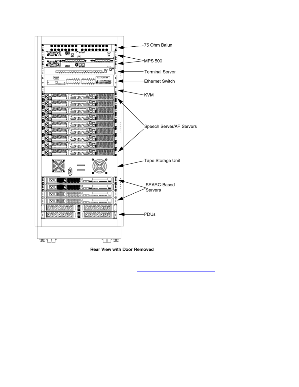
Hardware Overview
The Avaya Media Processing Server (MPS) 500 system consists of up to two chassis and two
application processors per cabinet. The MPS 500 has a capacity of 8 spans for a maximum of 192
(T1) or 240 (E1/VOIP) lines. Optional second application processors are available for redundancy or
other processing applications.
On the MPS 500, Interactive Voice Response (IVR) spans are specified in any configuration that
best meets application requirements and your preferences. Refer to your System Definition Package
(SDP) for the details of your configuration.
The MPS 500 system is available in a 52-inch 25 Rack Unit (RU) cabinet. The standalone MPS 500
can also be installed in a 43 RU cabinet or a 48 RU cabinet. For information about 43 RU and 48
RU cabinet configurations, see MPS 1000 Hardware Installation and Maintenance (NN44100-301).
10 Avaya Media Processing Server 500 Hardware Installation and Maintenance October 2014
Comments? infodev@avaya.com

Hardware Overview
Note:
The equipment depicted in the cabinet drawings that follow are samples showing the maximum
configuration. Each system configuration varies depending on the options chosen.
You can order a second 52-inch 25 RU cabinet to house optional equipment.
Figure 1: 25 RU (52) Cabinet Front view
October 2014 Avaya Media Processing Server 500 Hardware Installation and Maintenance 11
Comments? infodev@avaya.com
MPS 500 System Hardware Overview
Figure 2: 25 RU (52) Cabinet Rear View
For additional images of the MPS 500, see MPS 500 Sample Configurations on page 217.
12 Avaya Media Processing Server 500 Hardware Installation and Maintenance October 2014
Comments? infodev@avaya.com
MPS 500 Components
MPS 500 Components
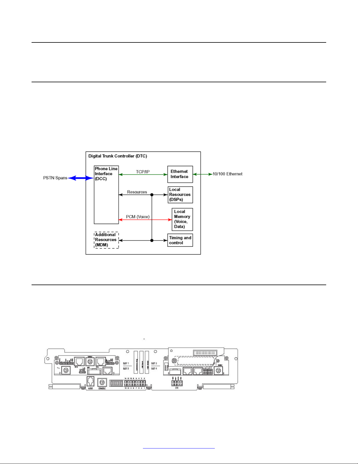
Digital Trunk Controller
The digital trunk controller (DTC) assembly is comprised of the telephony media server (TMS)
motherboard, the PLI, and the optional DCC/TPM/MDM cards. The DTC is responsible for lowerlevel functions, such as telephone line signalling, host communications, use of shared resources,
and message recording/playback.
The following diagram is a schematic of the DTC.
Telephony Media Server
The telephony media server (TMS) is a subcomponent of the DTC and refers to the TMS-2500
motherboard. The TMS motherboard supports optional daughterboards (TRR, PLI, DCC, MDM, and
so on), which are mounted to provide expanded resources and functionality, such as a PCM
interface, a SIP/RTP interface, and an SS7 interface.
Figure 3: TMS Assembly Front View
October 2014 Avaya Media Processing Server 500 Hardware Installation and Maintenance 13
Comments? infodev@avaya.com

MPS 500 System Hardware Overview
Telephone Line Interfaces
The DTC can support up to eight digital T1 or E1 spans using a single digital communications
controller (DCC) plug-in module to connect to the public switched telephone network (PSTN). The
DCC supports either T1 (24 channels/span for a total of 192 lines) or E1 (30 channels/span for a
total of 240 phone line) interfaces.
Only one Digital Communications Controller (DCC/PLI) combination can be installed in the DTC.
Any line can be either incoming or outgoing, and all ports are non-blocking (that is, any port can be
bridged to any other port).
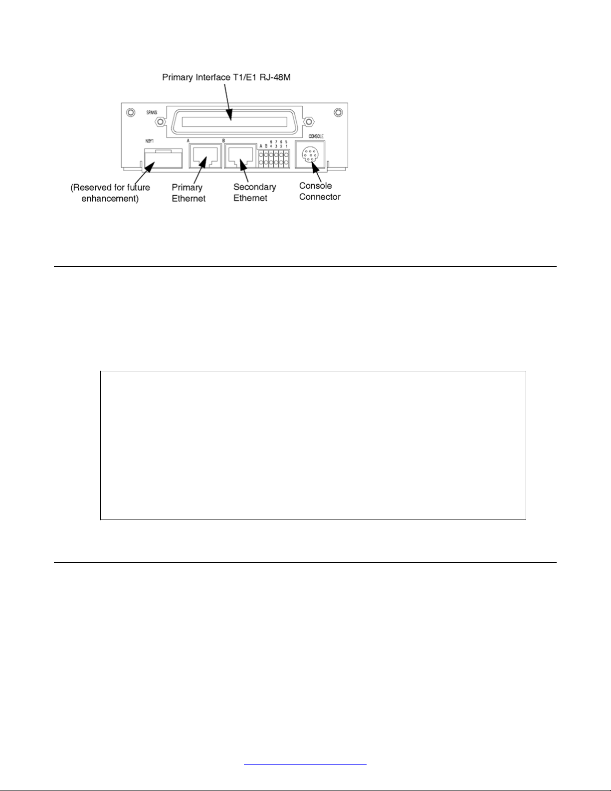
Digital Communications Controller (DCC)
The DCC provides the digital phone line interfaces for the system. It plugs into any of the two bottom
slots of the TMS. The DCC is dedicated for either a T1 or E1 system, and connects its phone line
interfaces to the PSTN (in the rear of the unit) with an RJ48M connector (up to eight spans) or eight
RJ48C connectors. A factory-ordered adapter is provided when RJ48C connectivity is required. See
Digital Interfaces on page 195.
The DCC/CTPM/TPM card sets are also capable of interfacing with a telephony network using SIP/
RTP. A DCC/CTPM/TPM has no telephony connector on the front panel. Refer to MPS 500 SIP and
RTP on page 29.
Qualified service personnel use the serial console connector for diagnostic purposes and for
verifying and configuring the boot ROM. See Field Programmable Gate Arrays on page 16. Other
connectors and indicators on the DCC front panel are reserved for future enhancement.
DCC-3000
The DCC-3000 is the newest version of the DCC family. The DCC-3000 adds two 10/100 Ethernet
ports and is available with or without full echo cancellation. The DCC-3000 can provide 256
channels of 64 millisecond (ms) echo cancellation. This feature is controllable by software on a perchannel basis.
To determine if echo cancellation is installed on the DCC-3000 board, run the following command:
From the command line, run the command devlist.
If the command returns the following:
CARD_ID 503647401A_.5036436017, echo cancellation is installed.
If the command returns the following:
CARD_ID 503647402A_.5036436017, echo cancellation is not installed.
Note:
The card ID on your system may not match the card IDs in this example. However, the last digit
in the first series of numbers (1 in CARD_ID 503647401) is a 1 on boards with echo cancellation
and a 2 on boards without echo cancellation.
14 Avaya Media Processing Server 500 Hardware Installation and Maintenance October 2014
Comments? infodev@avaya.com
Resources
Figure 4: DCC-3000 With PLI Front View
Resources
The TMS motherboard contains DSPs, which can be programmed to make resources available. A
resource must be available on the system for an application to use it. If the resident DSPs are fully
allocated to resources or protocols, you can add capacity for more resources by installing a Multiple
DSP Module (MDM) in an open TMS slot and loading the image definitions for the resources
required. Examples of TMS-supported resources are:
• Player ( ply ) - Vocabularies or audio data plays from local memory on the TMS
motherboard.
• DTMF Receiver ( dtmf ) and Call Progress Detection ( cpd ) - Phone line events,
such as touch-tone entry, hook-flash, dial tone, busy signals, and so on, are
detected.
• Tone Generator ( tgen ) - In lieu of playing tones as vocabularies, DTMF and
other tones are generated.
• R1 Transmit ( r1tx ), R1 Receive ( r1rx ), and R2 ( r2 ) - Tone generators and
detectors to support R1 and R2 protocols.
System LAN Interface
The DTC connects to the system LAN by Ethernet using TCP/IP. The primary Ethernet (designated
A) is connected with a cable to the Ethernet switch. An optional second Ethernet (designated B) and
optional second switch (cascaded) can provide redundant connectivity. Redundant Ethernet
provides automatic failover to the slave connection in the event of a failure in the primary network.
October 2014 Avaya Media Processing Server 500 Hardware Installation and Maintenance 15
Comments? infodev@avaya.com

MPS 500 System Hardware Overview
Computer Telephony (CT) Bus
Voice and audio data is transmitted throughout the MPS 500 over a synchronized CT bus system.
Multiple physical and logical protocol layers are used to implement voice communications so that
conversations can be bridged on a non-blocking basis.
At the lowest level, the MPS 500 supports three PCM audio encoding formats: A-Law; Mu-Law; and
Adaptive Differential Pulse Coded Modulation (ADPCM). The PCM data is transmitted between
bridged lines using time division multiplexing (TDM). The TDM transmission layer enables bridging
of conversations within spans and across spans. For redundancy, multiple clocking sources provide
synchronization of the CT bus.
Note:
The TMS can also be populated with a Multiple DSP Module (MDM), in one or more of the
remaining open slots. Although the motherboard has local digital signal processors, the MDM
provides additional resources for systems that require them.
Multiple DSP Module (MDM)
The TMS motherboard contains six digital signal processors (DSP), which can be configured for
communications protocols and to provide resources. The MDM contains 12 DSPs for the
configuration of additional resources. There are no indicators or connectors on the front panel of the
MDM. The only visible indication that an MDM is installed in a TMS slot (instead of a blank in the
slot), is the presence of bend tabs near the center of the front bracket that secure it to the MDM
circuit board. The following diagram shows the front view of an MDM when mounted in slot 2 only.
Figure 5: MDM Front View
For information about configuration of resources and protocols, see Configuring the Network on
page 57.
Field Programmable Gate Arrays
The TMS and the modules that plug into it (that is, DCC and MDM) contain Field Programmable
Gate Arrays (FPGA). An FPGA is a generic microchip that has no inherent functionality. It contains
arrays of generic logic elements (for example, gates) that are software configurable. The software
that configures the FPGA is called an image, and the image typically commands the FPGA to
assume the functionality of a designed logic circuit. A hardware architecture based on FPGAs is
very powerful and flexible because:
• A greater degree of complex logic functionality can be achieved in a relatively
smaller board space with fewer circuit components, compared to where
16 Avaya Media Processing Server 500 Hardware Installation and Maintenance October 2014
Comments? infodev@avaya.com

Terminal Server (Optional)
dedicated circuit components and hard board wiring are used. This also
provides greater circuit reliability.
• Functionality is enhanced without hardware redesign or even removal and
replacement. Upgrades are done in the field by loading a new image definition.
FPGA and the Boot ROM
FPGAs are dynamic devices because they do not retain their image definition when power is
removed. The image definition for each device is loaded from an image definition file (*.idf) during
the system boot sequence. The TMS contains a boot ROM that statically stores the names of
the .idf files for the devices contained on its motherboard and the modules that are plugged in.
Whenever a new system is installed, an existing system has components added or replaced, or the
system is upgraded, the boot ROM must be verified and, if necessary, modified. See
Modifying Boot ROM Settings on page 123.
Verifying and
Facsimile
The MDM can provide 8 DSPs for a total of 16 fax channels per TMS.
The following fax specifications are supported:
• CCITT T.4 and CCITT T.30 for Group III fax compatibility
• Fax pages: A4 only
• Data rate: 9600 baud with fallback rates of 7200/4800/2400 baud
Terminal Server (Optional)
The optional terminal server provides remote access for servers that have Lights Out Management
(LOM) capability. LOM capability is a service requirement and is accomplished through the use of a
terminal server or a VPN.
The terminal server can be configured to provide Telnet port access, remote access to any of the
application or speech processors connected to the server.
Figure 6: Terminal Server Rear View
Keyboard/Video/Mouse
The Keyboard/Video/Mouse (KVM) system has an integrated 15-inch LCD monitor with a keyboard
and mouse that is supplied in a one RU slide-out assembly. The servers are interconnected by a set
October 2014 Avaya Media Processing Server 500 Hardware Installation and Maintenance 17
Comments? infodev@avaya.com
MPS 500 System Hardware Overview
of control cables with which they can share a common KVM console. Server selection is through
keystrokes or by pressing the select switch on the front of the desired server.
Refer to the MPS Speech Server 6.0.1 Reference Guide for connection instructions.
Tape Storage Unit
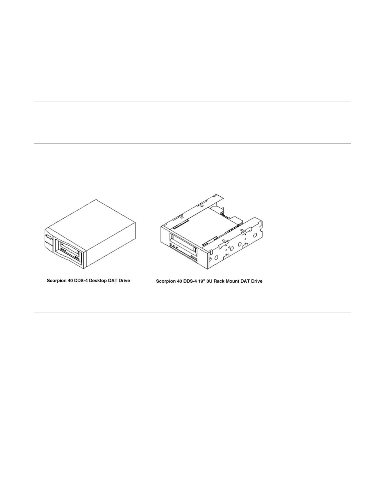
Digital Audio Tape (DAT) Drives
There are two types of DAT drives used with the MPS 500: The Seagate Scorpion 40 DDS-4
desktop drive and the Seagate Scorpion 40 DDS-4 19" 3U rack mount drive. The following
illustrations show the configurations.
One RU Servers Overview
The Avaya Speech Server platform is an expandable server platform designed to provide a range of
services that include various forms of Speech Recognition, Speech Verification, and Text-ToSpeech.
The Speech Server platform consists of a cluster of high-perfomance servers that are fully
integrated with the MPS 500. These servers can be in a completely fault tolerant environment that
includes redundant networking and storage capability. A total of seven servers can be installed in
one cabinet, and multiple cabinets can be linked for larger systems.
Application or speech processors supported in MPS 4.1 are listed in the following table.
18 Avaya Media Processing Server 500 Hardware Installation and Maintenance October 2014
Comments? infodev@avaya.com
IBM xSeries 3550
Server type Application
Processor
Sun Fire V215 yes no yes
Sun Fire V245 yes no yes 2U server
Sun Fire T2000 yes yes (only
Sun Fire T5120 yes yes (only
Sun Fire T5220 yes yes (only
Netra 240 yes yes (only
Netra T5220 yes yes (only
speech Redundant
Ethernet
yes 2U server
for
MRCPv1
client)
yes
for
MRCPv1
client)
yes 2U server
for
MRCPv1
client)
yes 2U server
for
MRCPv1
client)
yes 2U server
for
MRCPv1
client)
Notes
Server type Application
Processor
IBM x3550 yes yes yes
HP DL360 G5 yes yes yes
HP DL360 G7 yes yes yes
speech Tools Notes
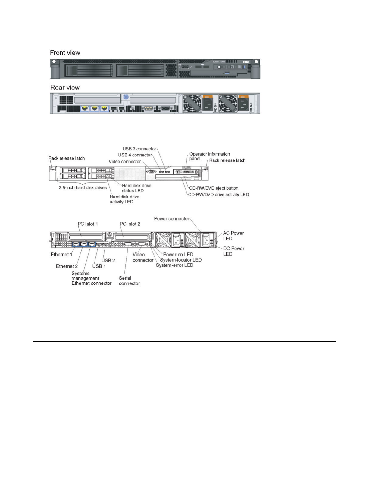
IBM xSeries 3550
The following diagrams show the front and rear view of the IBM x3550 type 7978 server.
October 2014 Avaya Media Processing Server 500 Hardware Installation and Maintenance 19
Comments? infodev@avaya.com
MPS 500 System Hardware Overview
Figure 7: Model A
Figure 8: Model B
Refer to the online Installation Guide for the IBM x3550 at
http://www.ibm.com
HP DL360 G5 Speech Server
The following diagram shows the HP ProLiant DL360 Generation 5p (G5p).
20 Avaya Media Processing Server 500 Hardware Installation and Maintenance October 2014
Comments? infodev@avaya.com

Refer to the online Installation Guide for the DL360 G5 at http://www.hp.com/
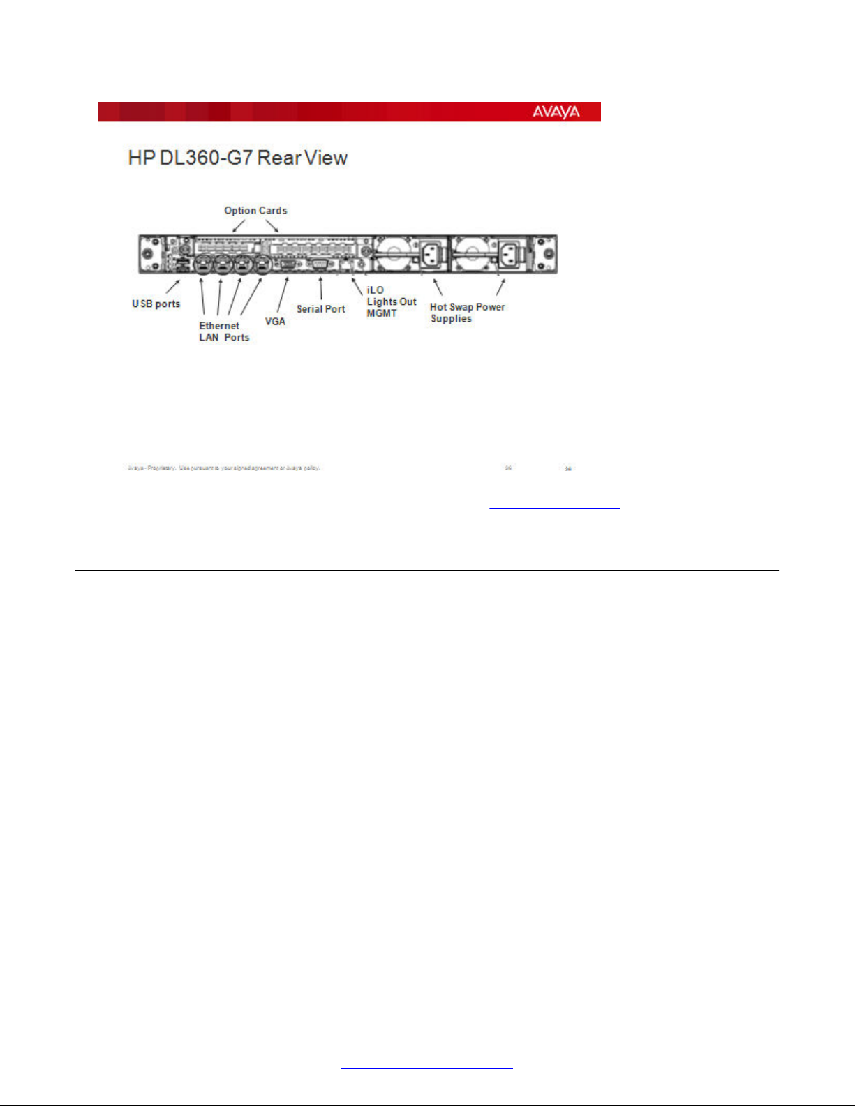
HP DL360 G7 Speech Server
The following diagram shows the HP DL360 G7 Speech Server.
HP DL360 G5 Speech Server
October 2014 Avaya Media Processing Server 500 Hardware Installation and Maintenance 21
Comments? infodev@avaya.com
MPS 500 System Hardware Overview
Refer to the online Installation Guide for the DL360 G7 at http://www.hp.com/
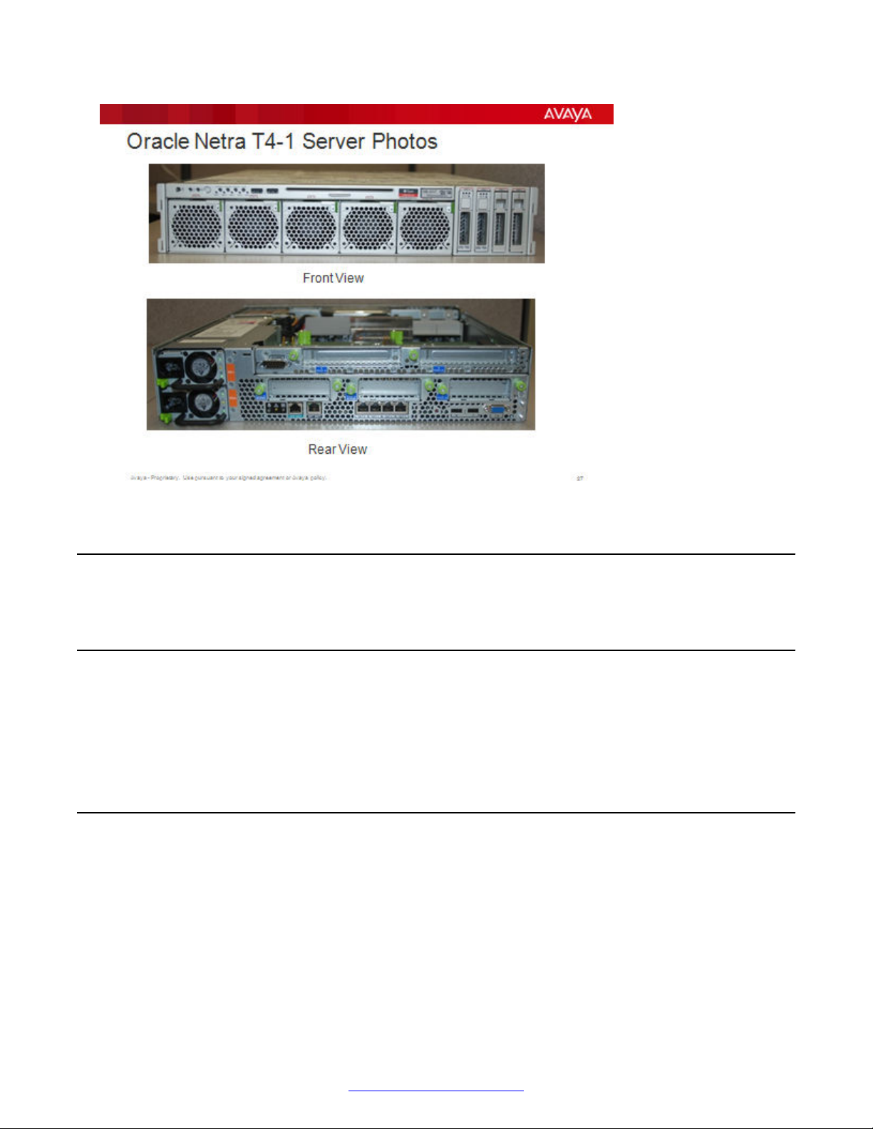
SPARC-Based Servers
Supporte the following Oracle server models through Solaris 2.10:
• V Series (V215, V245)
• T Series (T2000, T5120, T5220, T4-1)
• Netra 240
22 Avaya Media Processing Server 500 Hardware Installation and Maintenance October 2014
Comments? infodev@avaya.com
Power Distribution Unit
Power Distribution Unit
AC Power Distribution Panel
The AC Power Distribution Panels provide connectivity between cabinet-based items and the main
power. Avaya offers two types of AC power; front-end power distribution units (FE PDU) and backend power distribution units (BE PDU). The following sections describe these PDU.
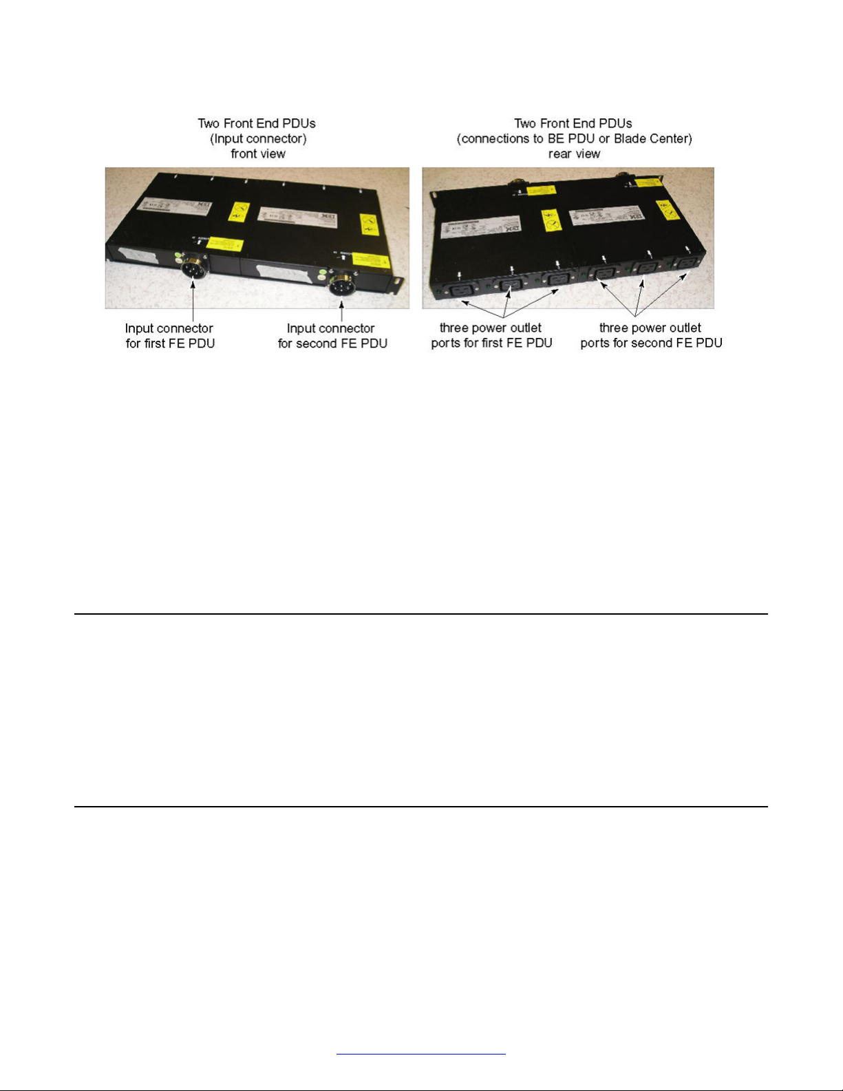
Front-end PDU overview
The following diagram shows the front and rear views of two FE PDU.
October 2014 Avaya Media Processing Server 500 Hardware Installation and Maintenance 23
Comments? infodev@avaya.com
MPS 500 System Hardware Overview
FE PDU are 200 to 250 VAC only. Each FE PDU has one power inlet port (input connector) and
three power outlet ports. The power outlet ports are IEC 320-C19 ports, with 16 amp rating.
Depending on the inlet cord type, you can connect up to three BE PDU. There are two types of input
connectors for each region.
• In non-EMEA countries, you can use two outlet ports only with an L6-30P connector for 30 amp
connectivity. You can use all outlet ports with an IEC 309-60A connector.
• In EMEA countries, you can use two outlet ports only with an IEC 309-32A connector for 30
amp connectivity. All outlet ports can be used with an IEC 309-63A connector.
• The Hubbell P/N for the connector is the 363P6W.
PDU Position
The FE PDU position in the cabinet depends on power considerations at the customer site. In most
instances, the power is supplied from the bottom of the cabinet and the FE PDU is situated there.
The input connector to the FE PDU faces the interior of the cabinet. This is to provide sufficient
clearance between the FE PDU and the cabinet mounted equipment. Refer to your System
Definition Package for the exact location of the PDU in your installation.
Back-end PDU overview
The following diagram shows two back end power distribution units (BE PDU).
24 Avaya Media Processing Server 500 Hardware Installation and Maintenance October 2014
Comments? infodev@avaya.com
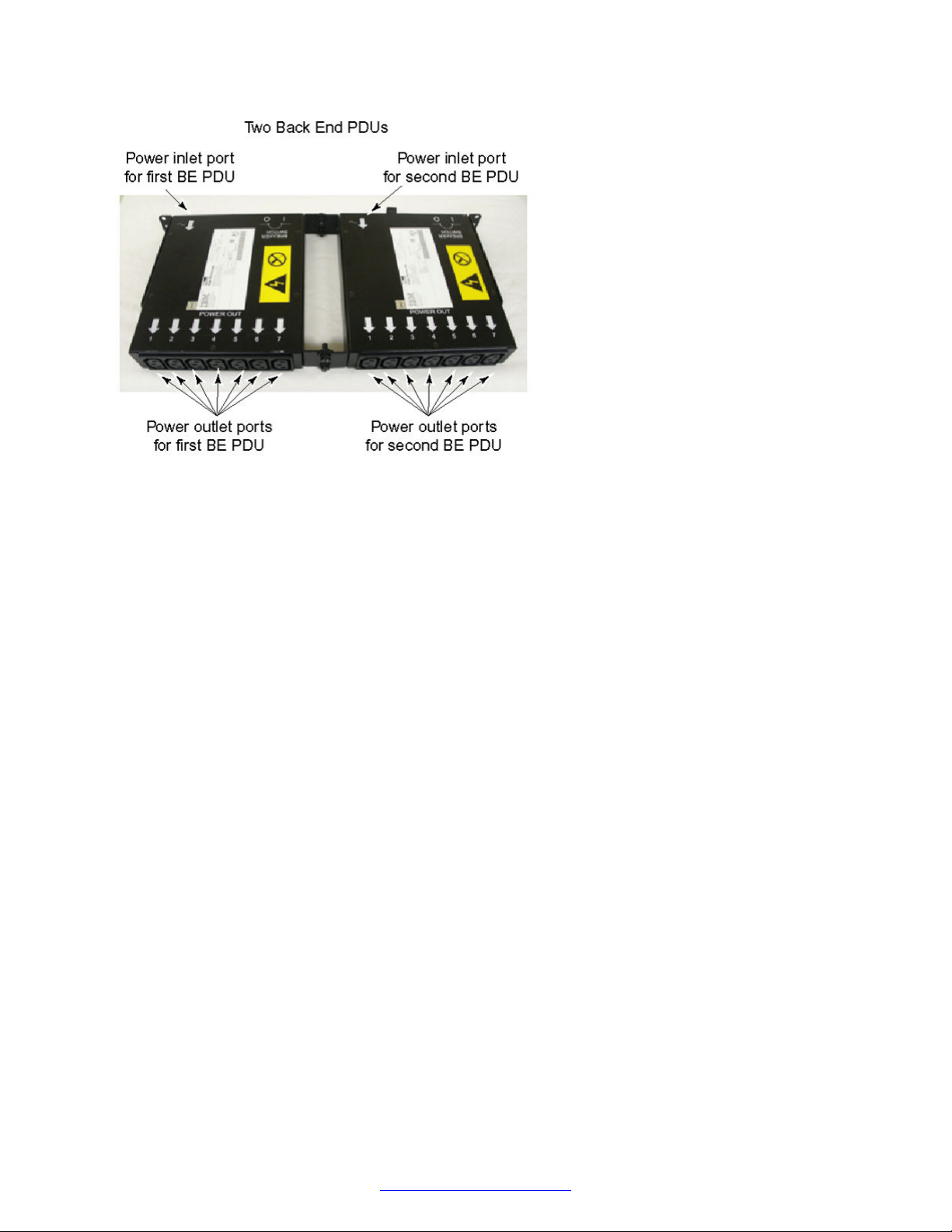
Back-end PDU overview
The dual BE PDU consists of two identical seven-outlet control boxes. Each control box can deliver
15 amps total and is protected by a 15-Amp circuit breaker. The number of usable connections
depends on the amperage draw (not voltage) of the attached equipment. Typically, five connections
are permitted. Each BE PDU has seven power outlet ports and one power inlet port. The power
outlet ports are IEC 320-C13s, which accommodate equipment line cords. The power inlet port is an
IEC 320-C19 port, which can use three different types of inlet line cord. The type of inlet line chord
depends on the connectivity desired. The types of inlet line cord are:
• L5-20P for 115 Vac connector
• L6-20P for 230 Vac connector
• IEC 320-C19 to IEC 320-C20 connector for FE PDU connectivity
Up to five of the following application or Speech Servers can be placed on a single BE PDU:
• IBM x3550
• HP DL360-G7 HP DL360-G5
• Oracle: V210, V240, V215, V245, Netra 240, T2000, T5120, T5220, Netra T4-1
Additional devices, such as KVM, fans, and switches, can share the BE PDU only if they do not
exceed the 15 amp maximum, regardless of voltage.
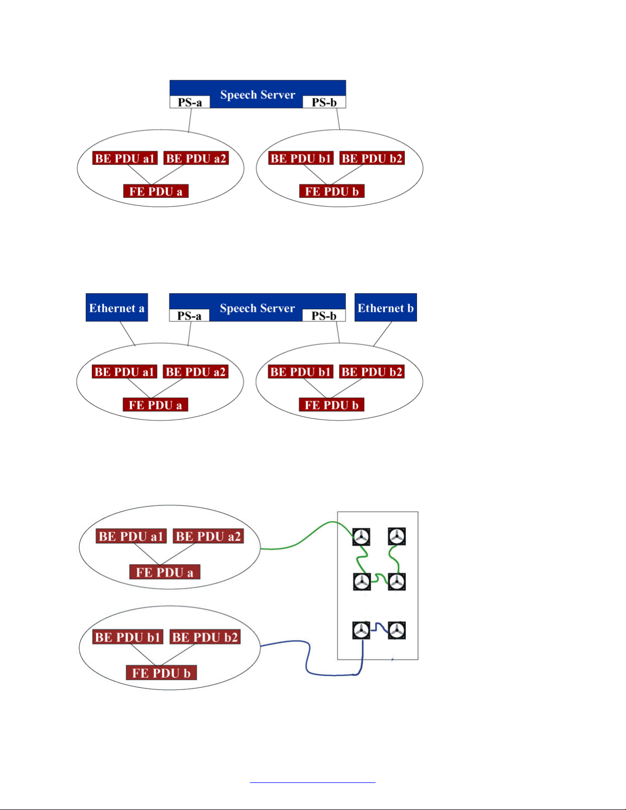
Redundant Power Supplies
Back end PDU supporting redundant power supplies must be attached to different front end PDU as
shown in the following example.
October 2014 Avaya Media Processing Server 500 Hardware Installation and Maintenance 25
Comments? infodev@avaya.com
MPS 500 System Hardware Overview
Redundant Ethernet
When configuring for server power or Ethernet redundancy, the A power supply and primary
Ethernet switch must be connected to a different PDU than the B power supply and secondary
Ethernet switch as shown in the following example.
Fan Circuits
The fan circuits must be connected to separate power sources to minimize single points of failure.
Therefore, if you have multiple power sources providing power to different PDU, ensure the fans are
split between two separate power sources where ever possible as shown in the following example.
26 Avaya Media Processing Server 500 Hardware Installation and Maintenance October 2014
Comments? infodev@avaya.com
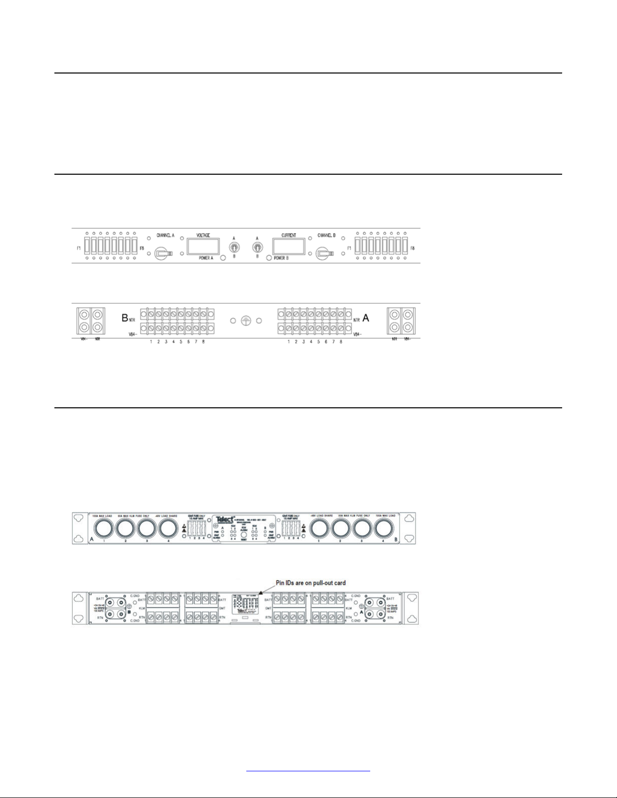
DC Power Distribution Unit
DC Power Distribution Unit
The Power Distribution Unit (PDU) supplies redundant power to components in the MPS cabinet (for
example, IBM servers and VRC chassis) that do not have their own redundant power supplies.
DC PDU
The front and rear views of the DC PDU are shown in the following diagrams.
Figure 9: DC PDU Front View
Figure 10: DC PDU Rear View
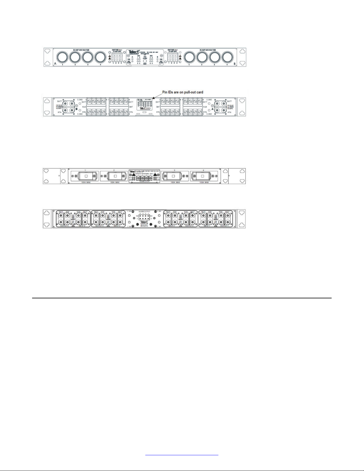
DC Fuse Panels and Circuit Breaker Panels
There are two types of fuse panels for DC power distribution; one with fail over capability and one
without fail over capability. The fuse panel with fail-over capability is for servers without dual power
supplies. The fuse panel without fail-over capability is for servers with dual power supplies, such as
the x3550 the Netra 240.
Figure 11: DC Fuse Panel with Fail-Over Capability Front View
Figure 12: DC Fuse Panel with Fail-Over Capability Rear View
October 2014 Avaya Media Processing Server 500 Hardware Installation and Maintenance 27
Comments? infodev@avaya.com
MPS 500 System Hardware Overview
Figure 13: DC Fuse Panel Front View
Figure 14: DC Fuse Panel Rear View
The DC circuit breaker provides breaker protection at the equipment interface. The output of the
circuit breaker panel connects to the input of the fuse panel. The input of the circuit breaker
connects to the DC PDU.
Figure 15: DC Circuit Breaker Panel Front View
Figure 16: DC Circuit Breaker Panel Rear View
The position of the circuit breaker and fuse panel within the cabinet is dependant on system
configuration. Circuit breaker and fuse panels can be installed at the top or bottom of the cabinet,
however the most common location is at the top.
Cooling
An MPS cabinet can produce a high amount of heat. Therefore, the cabinet is equipped with special
doors and cooling fans. The front is a ventilated door, and the back door has six 6-inch fans to
remove the air from the cabinet. The fans are wired as two separate circuits, one containing two
fans and one containing four.
28 Avaya Media Processing Server 500 Hardware Installation and Maintenance October 2014
Comments? infodev@avaya.com
Network Attached Storage
Network Attached Storage
Just a Bunch of Disks (JBOD)
JBOD units provide additional data storage for application or speech processors. The features of a
JBOD unit are:
• JBOD units available for AC and DC platforms
• support for multiple servers and operating systems
• local or remote management from a single console
• store up to 584 GB in 1U in 4 bays
• support 73 GB drives in 10 K or 15 K RPM or 146 GB drives in 10 K RPM
• high availability with RAID levels 0, 1, 0+1, 3
• hot serviceable with one RAID controller
• online RAID firmware updates
Figure 17: JBOD Rear View
MPS 500 SIP and RTP
The MPS 500 architecture is designed to implement of voice or vocabulary transmission over a
private or public IP network. The system is RFC 3261 SIP compliant, and users running any SIPcompliant client software can initiate or receive calls. Calls can be made from client to phone, phone
to client, or client to client. SIP and RTP interface from MPS is possible by using a CCSS SIP
Server and Card set consisting of a DCC/ CTPM and TPM (Trunk Pack Module). For more details
on SIP offering on MPS refer to document NN44100-130 Avaya Media Processing Server SIP
Features Manual.
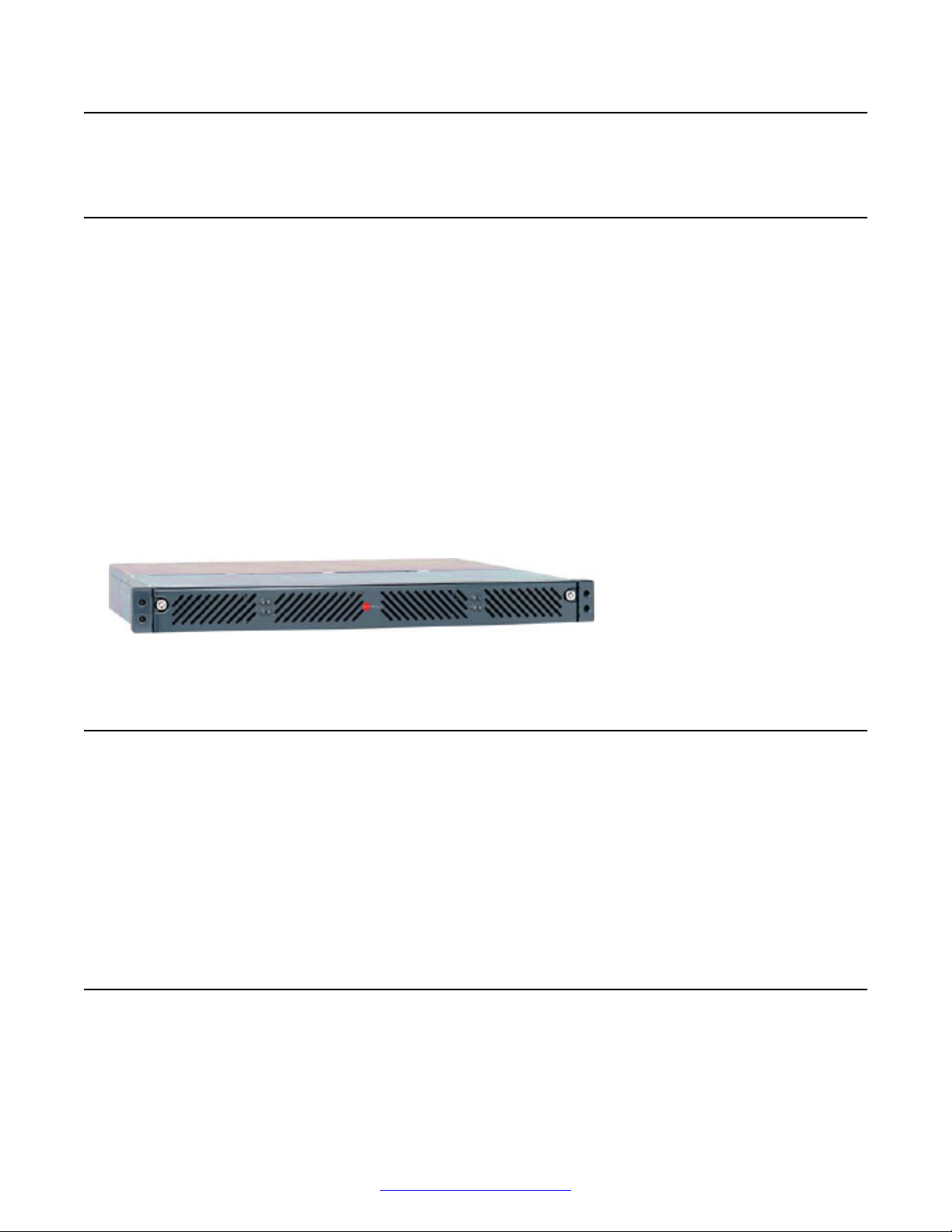
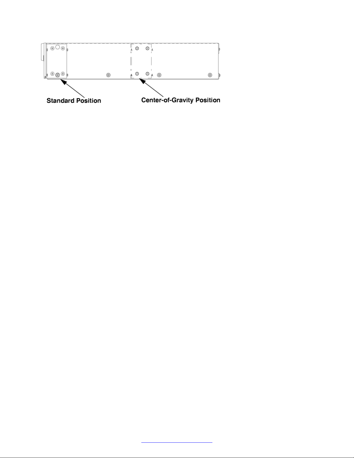
MPS 500 Standalone Chassis
The MPS 500 standalone assembly can be installed in a 19" customer-supplied rack. The following
diagram shows a side view of the rack mounting options.
October 2014 Avaya Media Processing Server 500 Hardware Installation and Maintenance 29
Comments? infodev@avaya.com
MPS 500 System Hardware Overview
Figure 18: Rack Mount Options
30 Avaya Media Processing Server 500 Hardware Installation and Maintenance October 2014
Comments? infodev@avaya.com
 Loading...