

Avaya Media Processing Server 1000 Hardware Installation And Maintenance

Avaya Media Processing Server 1000
Hardware Installation and Maintenance
Release 4.1
NN44100-301
Issue 01.01
October 2014

©
2014 Avaya Inc.
All Rights Reserved.
Notice
While reasonable efforts have been made to ensure that the
information in this document is complete and accurate at the time of
printing, Avaya assumes no liability for any errors. Avaya reserves
the right to make changes and corrections to the information in this
document without the obligation to notify any person or organization
of such changes.
Documentation disclaimer
“Documentation” means information published by Avaya in varying
mediums which may include product information, operating
instructions and performance specifications that Avaya may generally
make available to users of its products and Hosted Services.
Documentation does not include marketing materials. Avaya shall not
be responsible for any modifications, additions, or deletions to the
original published version of documentation unless such
modifications, additions, or deletions were performed by Avaya. End
User agrees to indemnify and hold harmless Avaya, Avaya's agents,
servants and employees against all claims, lawsuits, demands and
judgments arising out of, or in connection with, subsequent
modifications, additions or deletions to this documentation, to the
extent made by End User.
Link disclaimer
Avaya is not responsible for the contents or reliability of any linked
websites referenced within this site or documentation provided by
Avaya. Avaya is not responsible for the accuracy of any information,
statement or content provided on these sites and does not
necessarily endorse the products, services, or information described
or offered within them. Avaya does not guarantee that these links will
work all the time and has no control over the availability of the linked
pages.
Warranty
Avaya provides a limited warranty on Avaya hardware and software.
Refer to your sales agreement to establish the terms of the limited
warranty. In addition, Avaya’s standard warranty language, as well as
information regarding support for this product while under warranty is
available to Avaya customers and other parties through the Avaya
Support website:
http://support.avaya.com or such successor site as
designated by Avaya. Please note that if you acquired the product(s)
from an authorized Avaya Channel Partner outside of the United
States and Canada, the warranty is provided to you by said Avaya
Channel Partner and not by Avaya.
Licenses
THE SOFTWARE LICENSE TERMS AVAILABLE ON THE AVAYA
WEBSITE,
HTTP://SUPPORT.AVAYA.COM/LICENSEINFO OR
SUCH SUCCESSOR SITE AS DESIGNATED BY AVAYA, ARE
APPLICABLE TO ANYONE WHO DOWNLOADS, USES AND/OR
INSTALLS AVAYA SOFTWARE, PURCHASED FROM AVAYA INC.,
ANY AVAYA AFFILIATE, OR AN AVAYA CHANNEL PARTNER (AS
APPLICABLE) UNDER A COMMERCIAL AGREEMENT WITH
AVAYA OR AN AVAYA CHANNEL PARTNER. UNLESS
OTHERWISE AGREED TO BY AVAYA IN WRITING, AVAYA DOES
NOT EXTEND THIS LICENSE IF THE SOFTWARE WAS
OBTAINED FROM ANYONE OTHER THAN AVAYA, AN AVAYA
AFFILIATE OR AN AVAYA CHANNEL PARTNER; AVAYA
RESERVES THE RIGHT TO TAKE LEGAL ACTION AGAINST YOU
AND ANYONE ELSE USING OR SELLING THE SOFTWARE
WITHOUT A LICENSE. BY INSTALLING, DOWNLOADING OR
USING THE SOFTWARE, OR AUTHORIZING OTHERS TO DO SO,
YOU, ON BEHALF OF YOURSELF AND THE ENTITY FOR WHOM
YOU ARE INSTALLING, DOWNLOADING OR USING THE
SOFTWARE (HEREINAFTER REFERRED TO
INTERCHANGEABLY AS “YOU” AND “END USER”), AGREE TO
THESE TERMS AND CONDITIONS AND CREATE A BINDING
CONTRACT BETWEEN YOU AND AVAYA INC. OR THE
APPLICABLE AVAYA AFFILIATE (“AVAYA”).
Copyright
Except where expressly stated otherwise, no use should be made of
materials on this site, the Documentation, Software, Hosted Service,
or hardware provided by Avaya. All content on this site, the
documentation, Hosted Service, and the Product provided by Avaya
including the selection, arrangement and design of the content is
owned either by Avaya or its licensors and is protected by copyright
and other intellectual property laws including the sui generis rights
relating to the protection of databases. You may not modify, copy,
reproduce, republish, upload, post, transmit or distribute in any way
any content, in whole or in part, including any code and software
unless expressly authorized by Avaya. Unauthorized reproduction,
transmission, dissemination, storage, and or use without the express
written consent of Avaya can be a criminal, as well as a civil offense
under the applicable law.
Third Party Components
“Third Party Components” mean certain software programs or
portions thereof included in the Software or Hosted Service may
contain software (including open source software) distributed under
third party agreements (“Third Party Components”), which contain
terms regarding the rights to use certain portions of the Software
(“Third Party Terms”). As required, information regarding distributed
Linux OS source code (for those Products that have distributed Linux
OS source code) and identifying the copyright holders of the Third
Party Components and the Third Party Terms that apply is available
in the Documentation or on Avaya’s website at: http://
support.avaya.com/Copyright or such successor site as designated
by Avaya. You agree to the Third Party Terms for any such Third
Party Components.
Trademarks
The trademarks, logos and service marks (“Marks”) displayed in this
site, the Documentation, Hosted Service(s), and Product(s) provided
by Avaya are the registered or unregistered Marks of Avaya, its
affiliates, or other third parties. Users are not permitted to use such
Marks without prior written consent from Avaya or such third party
which may own the Mark. Nothing contained in this site, the
Documentation, Hosted Service(s) and Product(s) should be
construed as granting, by implication, estoppel, or otherwise, any
license or right in and to the Marks without the express written
permission of Avaya or the applicable third party.
Avaya is a registered trademark of Avaya Inc.
All non-Avaya trademarks are the property of their respective owners.
Linux® is the registered trademark of Linus Torvalds in the U.S. and
other countries.
Downloading Documentation
For the most current versions of Documentation, see the Avaya
Support website:
http://support.avaya.com, or such successor site as
designated by Avaya.
Contact Avaya Support
See the Avaya Support website:
http://support.avaya.com for Product
or Hosted Service notices and articles, or to report a problem with
your Avaya Product or Hosted Service. For a list of support telephone
numbers and contact addresses, go to the Avaya Support website:
http://support.avaya.com (or such successor site as designated by
Avaya), scroll to the bottom of the page, and select Contact Avaya
Support.

Contents
Chapter 1: MPS 1000 System Hardware Overview.............................................................. 10
MPS 1000 System................................................................................................................. 10
MPS 1000 Server Layout....................................................................................................... 10
Front Control Panel............................................................................................................... 12
Variable Resource Chassis.................................................................................................... 13
Telephony Media Server........................................................................................................ 16
VRC Rear Panel.................................................................................................................... 21
Network Interface Controller................................................................................................... 21
VRC Power Supplies............................................................................................................. 23
Standalone MPS 500............................................................................................................. 24
Application or Speech Processors.......................................................................................... 24
Terminal Server (Optional)..................................................................................................... 28
MPS 1000 Processor Layout.................................................................................................. 29
Speech Server Controls and Indicators................................................................................... 30
Power Distribution Unit.......................................................................................................... 30
AC Power Distribution Unit..................................................................................................... 30
BE PDU................................................................................................................................ 31
DC PDU............................................................................................................................... 34
DC Fuse Panels and Circuit Breaker Panels............................................................................ 34
Cooling................................................................................................................................. 35
Ethernet Switch..................................................................................................................... 35
Optional Switch/Router.......................................................................................................... 36
Console/Keyboard Sharing..................................................................................................... 36
Multiple Cabinet Console Sharing........................................................................................... 36
Network Attached Storage..................................................................................................... 37
Just a Bunch of Disks............................................................................................................ 37
MPS 1000 SIP and RTP........................................................................................................ 37
MPS 1000 Multiple Cabinet Systems...................................................................................... 38
Chapter 2: Installing Hardware and Connectivity................................................................ 39
Overview.............................................................................................................................. 39
System installation check list.................................................................................................. 39
Installing MPS Cabinets......................................................................................................... 40
Preparing Equipment for Installation....................................................................................... 40
Raised Floor Access.............................................................................................................. 41
Cabinet Weight..................................................................................................................... 41
Installing Earthquake Bracing................................................................................................. 41
Cabinet Base Drilling and Cutout Pattern................................................................................. 42
Drilling the Floor.................................................................................................................... 42
Installing Anchor Brackets on 84 inch Cabinet......................................................................... 43
Installing Anchors.................................................................................................................. 43
October 2014 Avaya Media Processing Server 1000 Hardware Installation and Maintenance 3
Comments? infodev@avaya.com

Contents
Installing Cables and Power................................................................................................... 44
Installing Cables.................................................................................................................... 44
Installing Overhead Cables.................................................................................................... 44
Installing Under Floor Cables................................................................................................. 44
Installing Power and Ground Wiring........................................................................................ 45
Installing Safety Ground and Protective Earth Wiring................................................................ 45
Installing AC Power............................................................................................................... 47
Installing DC Power............................................................................................................... 47
System Warning Label Locations............................................................................................ 49
Connecting to External Equipment.......................................................................................... 51
Connecting to PSTN Spans.................................................................................................... 51
TelCo Connector Panel.......................................................................................................... 51
Connecting Local Area Networks............................................................................................ 52
Cascade Cables for Ethernet Switches................................................................................... 54
Connecting to Internal Components........................................................................................ 54
ATM Connections.................................................................................................................. 54
SC Simplex Panel................................................................................................................. 54
SC Duplex Panel................................................................................................................... 54
Cable Polarity....................................................................................................................... 54
Primary Cabinet.................................................................................................................... 55
Secondary Cabinet................................................................................................................ 56
Tertiary Cabinet.................................................................................................................... 56
Standalone Cabinet............................................................................................................... 57
Handling Optical Cables......................................................................................................... 57
ATM Switch VPI Mapping Table............................................................................................. 59
Connecting Serial Ports......................................................................................................... 60
Connecting Through a Terminal Server................................................................................... 60
Cable Connect Table with Terminal Server.............................................................................. 61
Connecting System Clocks..................................................................................................... 62
Connecting Alarm Systems.................................................................................................... 63
Alarm Circuits....................................................................................................................... 63
Keyboard/Video/Mouse Switching........................................................................................... 63
Server Control Connections................................................................................................... 64
Keyboard/Video/Mouse Connections with AC Power................................................................ 64
Keyboard/Video/Mouse Connections with DC Power................................................................ 65
Server Attached Storage........................................................................................................ 66
Installing a JBOD Unit............................................................................................................ 66
Installing a RAID Unit............................................................................................................. 66
Customer-Supplied USB Modem............................................................................................ 67
Software Installation.............................................................................................................. 67
MPS Manager Workstation Installation.................................................................................... 67
Single Site Installations.......................................................................................................... 68
Multiple Site Installations........................................................................................................ 70
4 Avaya Media Processing Server 1000 Hardware Installation and Maintenance October 2014
Comments? infodev@avaya.com

Contents
Preparing for Power-Up......................................................................................................... 71
Connecting Power................................................................................................................. 72
Chapter 3: Configuration........................................................................................................ 73
Network Configuration........................................................................................................... 73
Configuring Network IP Addresses.......................................................................................... 73
DCC Boot Rom Configuration................................................................................................. 74
TMS Boot ROM Configuration................................................................................................ 74
NIC 2000 Boot Rom Configuration.......................................................................................... 75
Application Processor (AP) Network Configuration................................................................... 75
Netinstall Configuration Script................................................................................................ 78
Configuration Files................................................................................................................ 80
MPSHOME........................................................................................................................... 80
MPS 1000 Solaris Directory Structure..................................................................................... 81
Target Distribution directory................................................................................................... 82
MPS 1000 Windows Directory Structure.................................................................................. 83
Configuration Files................................................................................................................ 84
Common file directory............................................................................................................ 84
mpsN/etc directory................................................................................................................ 85
mpsN/apps directory.............................................................................................................. 85
packages directory................................................................................................................ 85
SIP/RTP............................................................................................................................... 86
Directory Structure................................................................................................................ 86
Configuration of bootp Daemon.............................................................................................. 87
ATM Switch Configuration...................................................................................................... 88
Loading Spans...................................................................................................................... 88
Configuring DCC................................................................................................................... 89
Testing the DCC and TPM Configuration................................................................................. 91
Application Support............................................................................................................... 94
Configuring the Terminal Server............................................................................................. 94
Telnet Port Access................................................................................................................ 94
Initial Setup........................................................................................................................... 95
Terminal Server Command Line Login.................................................................................... 96
Default Network Settings........................................................................................................ 97
Saving the Settings................................................................................................................ 98
Displaying the Network Settings............................................................................................. 98
Testing the Server Network Interface...................................................................................... 99
Terminal Server Graphical User Interface.............................................................................. 100
Making the Initial Connection................................................................................................ 100
Initial Login......................................................................................................................... 101
Admin Mode....................................................................................................................... 101
Setting Up the Async Ports................................................................................................... 102
Creating the perippp user account using the GUI................................................................... 107
Configuring And Updating the Terminal Server through TFTP................................................. 110
October 2014 Avaya Media Processing Server 1000 Hardware Installation and Maintenance 5
Comments? infodev@avaya.com

Contents
Hosts File Configuration....................................................................................................... 116
Using the Terminal Server.................................................................................................... 116
Configuring the binding order............................................................................................... 116
Configuring Redundant Ethernet........................................................................................... 117
Enabling Redundant Ethernet Mode..................................................................................... 117
Configuring IPMP for Windows-Based Processors................................................................. 117
HP DL360........................................................................................................................... 117
Configuring IPMP for Solaris Based Processors..................................................................... 119
Sun Netra........................................................................................................................... 119
Configuring Server Attached Storage.................................................................................... 124
JBOD................................................................................................................................. 124
RAID.................................................................................................................................. 124
Enabling Remote Desktop Connection on Windows Systems Only.......................................... 131
NetMeeting Setup and Configuration..................................................................................... 131
Remote Desktop Sharing Setup and Configuration................................................................. 134
Verifying and Modifying Boot ROM Settings.......................................................................... 139
DCC Boot ROM.................................................................................................................. 140
TMS Boot ROM................................................................................................................... 142
NIC Boot ROM.................................................................................................................... 144
Resetting the NIC................................................................................................................ 147
System Self Tests............................................................................................................... 148
Power Up Diagnostics......................................................................................................... 148
TMS Startup LED Sequence................................................................................................ 148
NIC Startup LED Sequence.................................................................................................. 151
Simple System Tests........................................................................................................... 155
Span Loop-Back Test.......................................................................................................... 155
Debug Terminal Connection................................................................................................. 158
Connect Using a Dumb Terminal or PC................................................................................. 158
Connect from the System Console........................................................................................ 158
Final Check......................................................................................................................... 159
Chapter 4: Operation and Administration.......................................................................... 160
Introduction to MPS Operating Procedures............................................................................ 160
MPS Indicators and Controls................................................................................................ 160
Front Control Panel............................................................................................................. 160
TMS Front Panel................................................................................................................. 161
Ethernet Hub Indicators....................................................................................................... 163
VRC Rear Panel.................................................................................................................. 163
ESC 2000 LED Status Interface............................................................................................ 164
Startup and Shutdown......................................................................................................... 168
Routine MPS Startup........................................................................................................... 168
Logon and Logoff................................................................................................................ 169
System Shutdown............................................................................................................... 170
Emergency Shutdown.......................................................................................................... 171
6 Avaya Media Processing Server 1000 Hardware Installation and Maintenance October 2014
Comments? infodev@avaya.com

Contents
Command Line Start and Stop.............................................................................................. 171
To Stop All Applications....................................................................................................... 171
To Start the system............................................................................................................. 172
Troubleshooting System Initialization.................................................................................... 172
VRC Front Panel LED Description........................................................................................ 172
NIC and TMS System Alarm Monitoring................................................................................ 172
TMS Diagnostics................................................................................................................. 175
TMS System Status............................................................................................................. 175
TMS Software Initialization and Loading Errors...................................................................... 176
TMS Runtime Alarms........................................................................................................... 177
TMS Resource errors.......................................................................................................... 177
TMS Spans......................................................................................................................... 178
Power Supply Runtime Alarms............................................................................................. 182
TMS Hardware.................................................................................................................... 184
NIC Diagnostics.................................................................................................................. 184
Bridging or Time Space Switch............................................................................................. 187
ATM................................................................................................................................... 188
Ethernet............................................................................................................................. 190
I2C..................................................................................................................................... 191
Memory.............................................................................................................................. 192
Chapter 5: System Validation.............................................................................................. 193
Hardware Validation............................................................................................................ 193
Field Factory Test................................................................................................................ 193
Field Factory Test Documentation........................................................................................ 193
Accessing FFT Documentation from a Sun Console............................................................... 194
Accessing FFT Documentation from a PC............................................................................. 194
Server Management............................................................................................................ 195
Sparc Based Processor....................................................................................................... 195
Lights Out Management (LOM)............................................................................................ 195
Chapter 6: Maintenance....................................................................................................... 196
Backup And Restore Procedures.......................................................................................... 196
Crash Recovery.................................................................................................................. 196
Mirrored Disk Backup and Recovery..................................................................................... 196
Crash Recovery for Solaris-Based Servers............................................................................ 197
World Wide Name Syntax and Mapping................................................................................ 197
Backup and Restore............................................................................................................ 202
Backup and Restore for Windows Servers............................................................................. 202
Performing a DVD rollout (WIM)........................................................................................... 203
Performing the post rollout steps.................................................................................... 204
Performing post rollout steps for Windows 2003............................................................... 207
Activating Windows 2008............................................................................................... 208
Speech Server Restore Procedure........................................................................................ 216
Removing, Replacing, and Adding Assemblies...................................................................... 217
October 2014 Avaya Media Processing Server 1000 Hardware Installation and Maintenance 7
Comments? infodev@avaya.com

Contents
Replacing a Front Control Panel (FCP)................................................................................. 217
Removing and Replacing a TMS or MDM.............................................................................. 217
Replacing a NIC.................................................................................................................. 221
Upgrading a DCC-2000 to a DCC-3000................................................................................. 221
Installation and Testing Procedure........................................................................................ 221
System Configuration.......................................................................................................... 222
VRC Chassis Replacement.................................................................................................. 223
TMS Assembly Components................................................................................................ 225
PLI Switch Settings.............................................................................................................. 226
Replacing a VRC Power Supply........................................................................................... 227
Replacing an Ethernet Switch............................................................................................... 230
Replacing a Windows Server................................................................................................ 231
Replacing a Sparc Based Server.......................................................................................... 231
Replacing a Terminal Server................................................................................................ 232
Replacing a Cooling Fan...................................................................................................... 232
Replacing an Ethernet Switch............................................................................................... 232
Chapter 7: MPS Specifications............................................................................................ 233
MPS Specifications.............................................................................................................. 233
Physical Specifications MPS Tall (90-Inch) Cabinet................................................................ 233
Physical Specifications MPS (84-Inch) Cabinet...................................................................... 234
Weight Specifications MPS Processor General...................................................................... 234
AC Electrical Specifications MPS Standard Cabinet............................................................... 234
DC Electrical Specifications MPS Standard Cabinet............................................................... 235
AC Electrical Specifications MPS Processor Cabinet.............................................................. 236
DC Electrical Specifications MPS Processor Cabinet............................................................. 236
Environmental Characteristics MPS Cabinet.......................................................................... 237
Network Telephone Interfaces.............................................................................................. 238
Voice LAN Interface............................................................................................................. 238
External Alarm Interfaces..................................................................................................... 239
Telephony Interfaces........................................................................................................... 239
Digital Interfaces................................................................................................................. 239
RJ48M............................................................................................................................... 239
RJ48C................................................................................................................................ 241
DB-9 to RJ-45 Serial adapter................................................................................................ 244
SPARC Adapter Wiring Diagram.......................................................................................... 245
Terminal Server Adapter Wiring Diagram (350-0308)............................................................. 245
SPARC RJ45 Pinouts.......................................................................................................... 246
Terminal Server Cable......................................................................................................... 246
MPS Terminal Cable............................................................................................................ 246
Chapter 8: MPS System Installation Checklist and Report............................................... 248
Order And Contact Information............................................................................................. 248
Completion Instructions....................................................................................................... 249
Installation Requirements..................................................................................................... 249
8 Avaya Media Processing Server 1000 Hardware Installation and Maintenance October 2014
Comments? infodev@avaya.com

Contents
Hardware Installation........................................................................................................... 250
Receipt Of Equipment.......................................................................................................... 250
Site Status.......................................................................................................................... 251
Deviations And General Status............................................................................................. 251
Installation Check List.......................................................................................................... 252
Unpack And Inventory Order................................................................................................ 252
System Setup..................................................................................................................... 252
Powering Up The System..................................................................................................... 253
AP and LAN Configuration (defaults)..................................................................................... 253
AP and LAN Configuration (Site specific)............................................................................... 254
AP and System Testing....................................................................................................... 254
System Backup................................................................................................................... 255
Sign Off Page..................................................................................................................... 255
Chapter 9: MPS 1000 Cabinet Configurations.................................................................... 257
October 2014 Avaya Media Processing Server 1000 Hardware Installation and Maintenance 9
Comments? infodev@avaya.com

Chapter 1: MPS 1000 System Hardware
Overview
MPS 1000 System
The Avaya Media Processing Server (MPS) 1000 system is contained within one or more standard
(84'') or tall (90'') Avaya cabinets. A large MPS 1000 system can consist of one or more server and
processor cabinets. Refer to your System Definition Package (SDP) for the list of components in
your system.
MPS 1000 Server Layout
The layout of the major components in a basic MPS 1000 Server is shown in the following diagrams.
10 Avaya Media Processing Server 1000 Hardware Installation and Maintenance October 2014
Comments? infodev@avaya.com
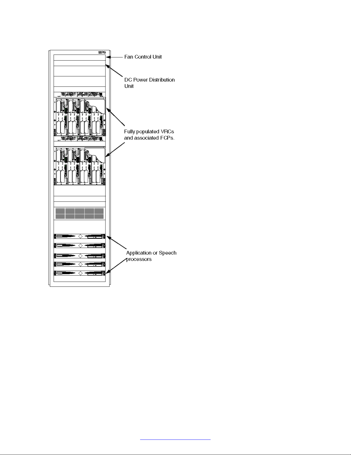
MPS 1000 Server Layout
Figure 1: Front View of MPS 1000 Server in 84 inch Cabinet
October 2014 Avaya Media Processing Server 1000 Hardware Installation and Maintenance 11
Comments? infodev@avaya.com
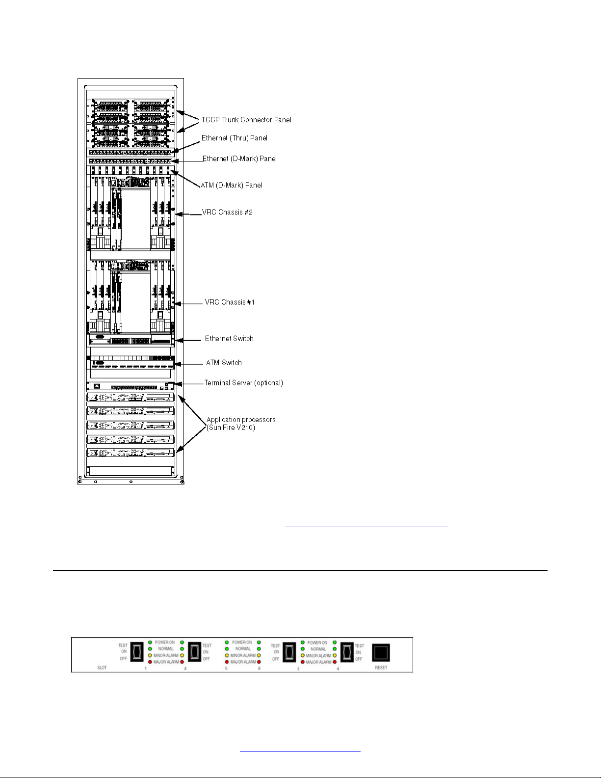
MPS 1000 System Hardware Overview
Figure 2: Rear View of MPS 1000 Server in 90 inch Cabinet
For additional images of cabinet layouts, see MPS 1000 Cabinet Configurations on page 257.
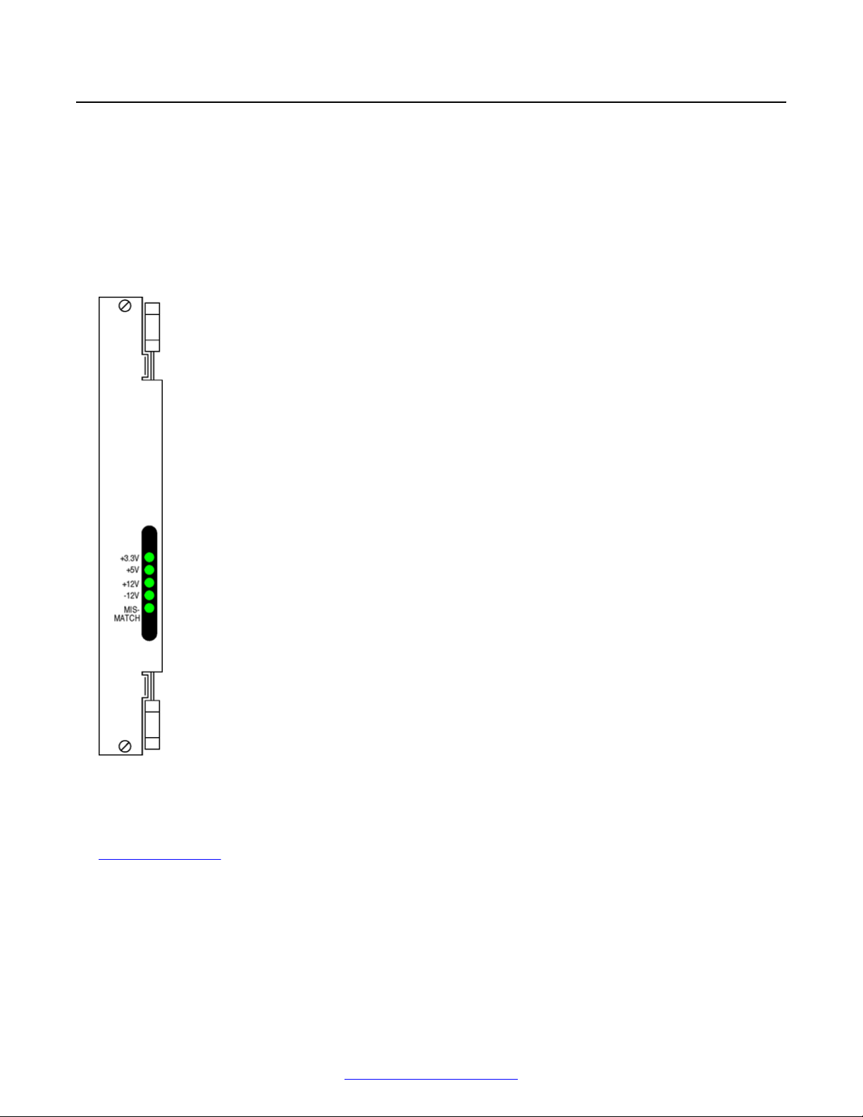
Front Control Panel
There is one Front Control Panel (FCP) for each Variable Resource Chassis (VRC) in the MPS
cabinet. the front of the FCP is shown in the following diagram.
12 Avaya Media Processing Server 1000 Hardware Installation and Maintenance October 2014
Comments? infodev@avaya.com
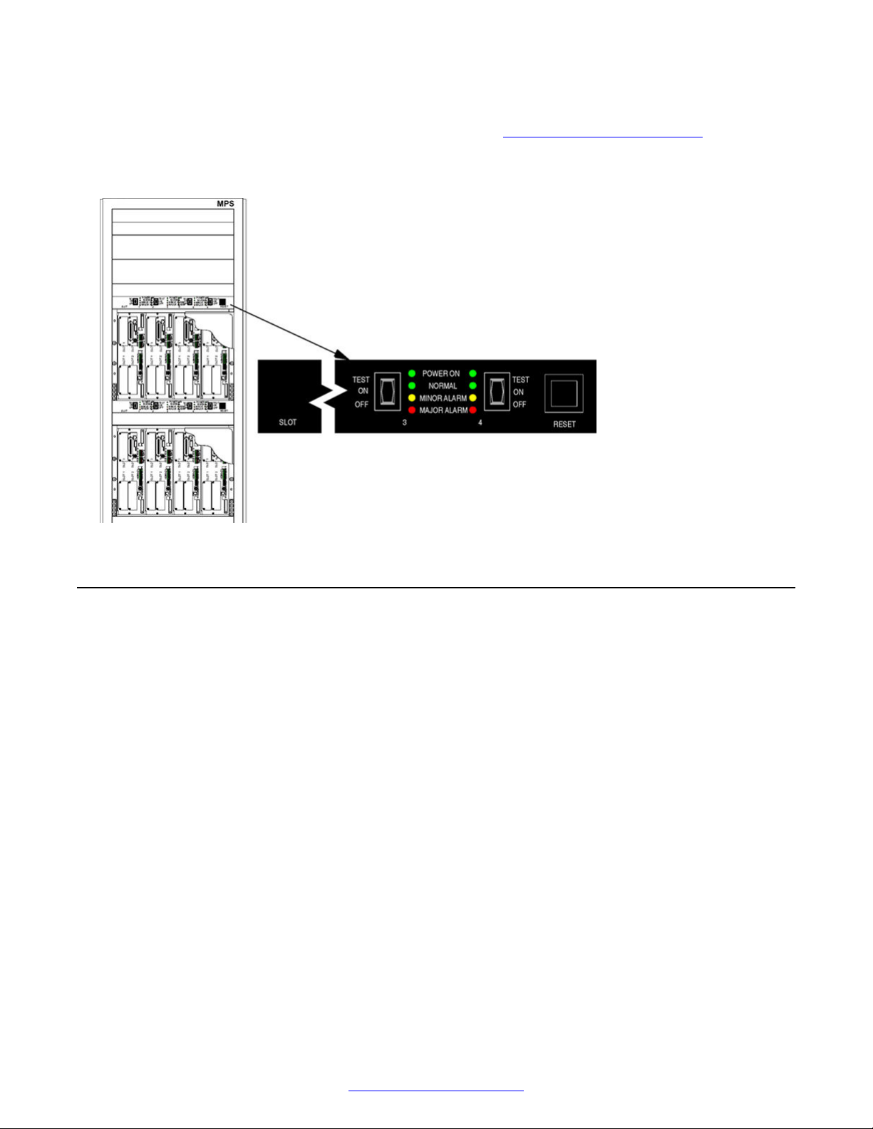
Variable Resource Chassis
The FCP provides switches to control power to slots in the associated VRC, to test the power
supplies, and indicators to display status and alarms. See MPS Indicators and Controls on
page 160.
The location of an FCP in an MPS cabinet is shown in the following diagram.
Variable Resource Chassis
When used in an MPS 1000 Server, the VRC contains:
• up to four Telephony Media Server (TMS) assemblies configured as Digital Trunk Controllers
(DTC)
• one auxiliary processor board
• one or two Network Interface Controllers
• up to five power supplies, one for each populated slot
• two available drive bays
The VRC has four front and two rear plug-in slots.
October 2014 Avaya Media Processing Server 1000 Hardware Installation and Maintenance 13
Comments? infodev@avaya.com
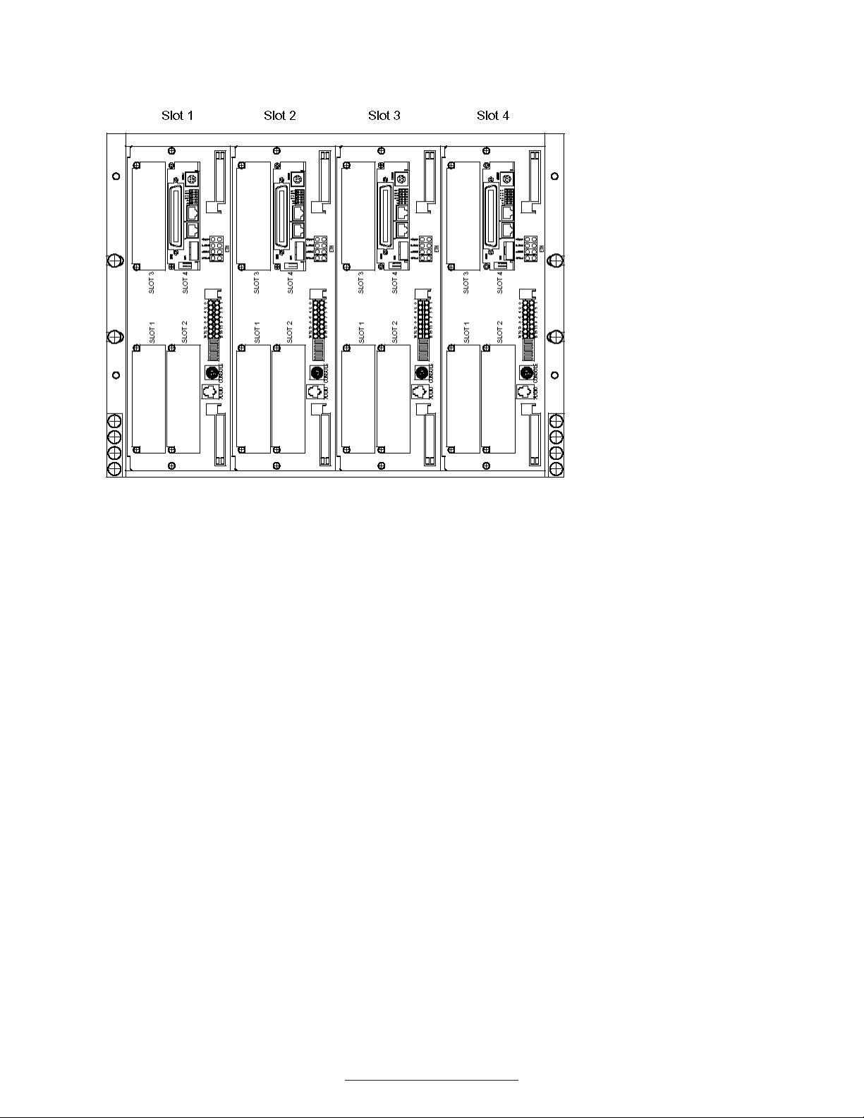
MPS 1000 System Hardware Overview
Figure 3: VRC Front View (Populated with Four TMS)
14 Avaya Media Processing Server 1000 Hardware Installation and Maintenance October 2014
Comments? infodev@avaya.com
Variable Resource Chassis
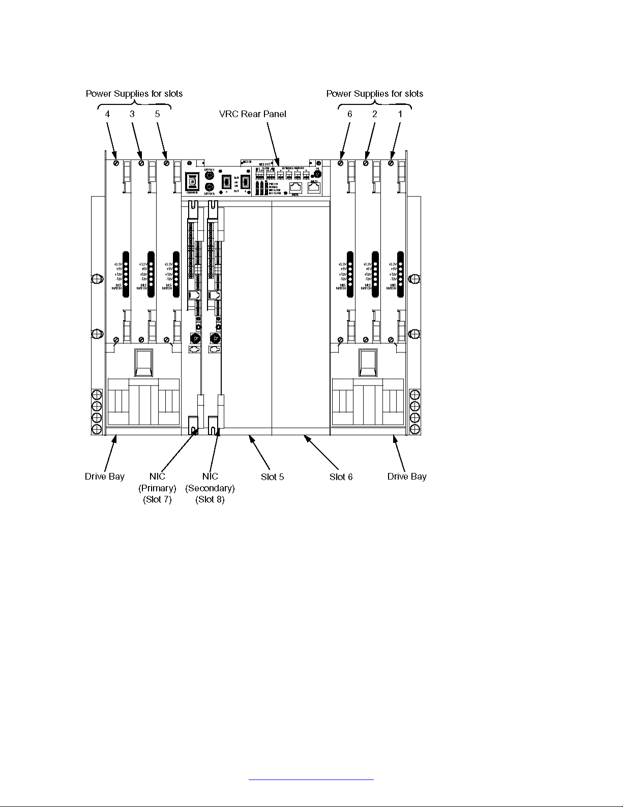
Figure 4: VRC Rear View
The following schematic shows the connections between components within the VRC and external
equipment.
October 2014 Avaya Media Processing Server 1000 Hardware Installation and Maintenance 15
Comments? infodev@avaya.com
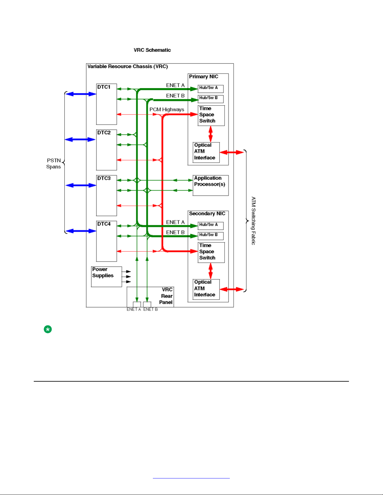
MPS 1000 System Hardware Overview
Figure 5: VRC Schematic
Note:
In multiple chassis and cabinet systems, some VRCs, do not contain all the assemblies shown
in the preceding diagram.
Telephony Media Server
The Avaya Telephony Media Server (TMS) is the core functional module of the MPS 1000. The
basic TMS assembly contains local data processors, shared memory, digital signal processors
(DSP) for basic resources, data network interfaces (Ethernet), and Computer Telephony (CT) bus
interfaces for voice communications.
16 Avaya Media Processing Server 1000 Hardware Installation and Maintenance October 2014
Comments? infodev@avaya.com
Telephony Media Server
The TMS is installed with at least one phone line interface, a Digital Communications Controller
(DCC), in one of the four slots.
Note:
The TMS can also be populated with a Multiple DSP Module (MDM), in one or more of the
remaining open slots.
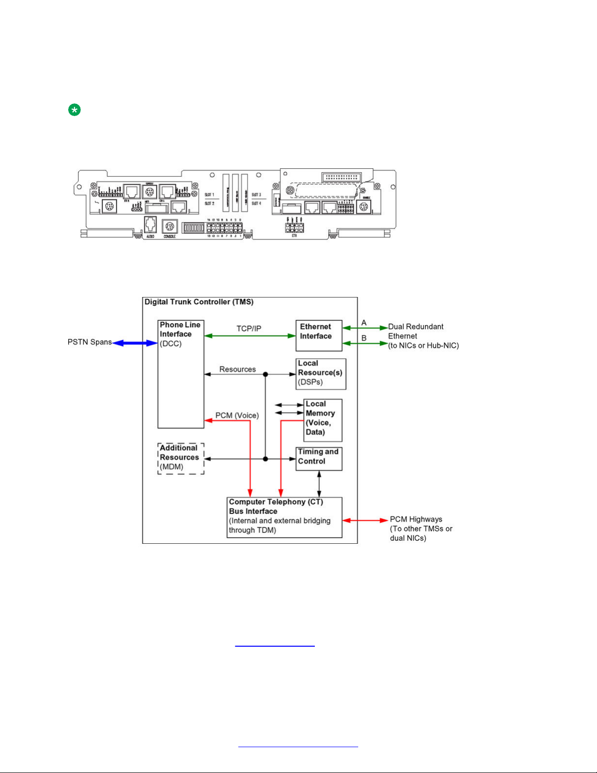
Figure 6: TMS Assembly Front View
The internal and external connections of the TMS are shown in the following schematic.
Figure 7: TMS Schematic
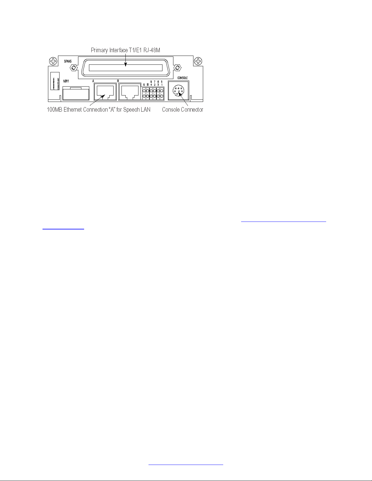
Digital Communications Controller (DCC)
The Digital Communications Controller (DCC) provides the digital phone line interfaces for the
system. The DCC can be plugged into any of the four slots of the TMS. The DCC is dedicated for
either a T1 or E1 system and connects phone line interfaces to the PSTN through an RJ48M
connector (up to eight spans). See
The DCC/CTPM/TPM card set can also interface with a telephony network using SIP/RTP. A DCC/
CTPM/TPM configured for SIP/RTP has no telephony connector on the front panel.
October 2014 Avaya Media Processing Server 1000 Hardware Installation and Maintenance 17
Digital Interfaces on page 239.
Comments? infodev@avaya.com
MPS 1000 System Hardware Overview
Qualified service personnel use the serial console connector for diagnostic purposes and for
verifying and configuring the boot ROM. See Field Programmable Gate Arrays on page 19.
Other connectors and indicators are provided on the DCC front panel but are reserved for future
enhancement.
DCC-3000
The DCC-3000 is the newest version of the DCC family. The DCC-3000 adds two 10/100 Ethernet
ports and is available with or without full echo cancellation. The DCC-3000 can provide 256
channels of 64 millisecond (ms) echo cancellation. This feature is controllable by software on a perchannel basis.
To determine if echo cancellation is installed on the DCC-3000 board, run the following command:
From the command line, run the command devlist.
If the command returns the following:
CARD_ID 503647401A_.5036436017, echo cancellation is installed.
If the command returns the following:
CARD_ID 503647402A_.5036436017, echo cancellation is not installed.
Note:
The card ID on your system may not match the card IDs in this example. However, the last digit
in the first series of numbers (1 in CARD_ID 503647401) is a 1 on boards with echo cancellation
and a 2 on boards without echo cancellation.
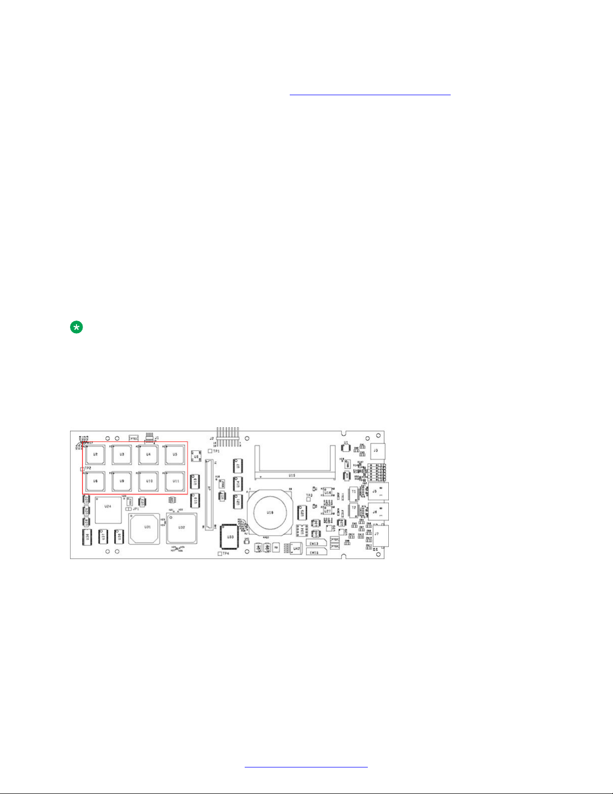
You can also determine if echo cancellation is installed by looking at the top view of the DCC-3000.
The following diagram shows a DCC-3000 with echo cancellation (area enclosed by the red
rectangle). If this area is not populated, echo cancellation is not installed.
Figure 8: DCC-3000 Top View
18 Avaya Media Processing Server 1000 Hardware Installation and Maintenance October 2014
Comments? infodev@avaya.com
Telephony Media Server
Figure 9: DCC-3000 With PLI Front View
Field Programmable Gate Arrays
The TMS and the modules that plug into it, contain Field Programmable Gate Arrays (FPGAs). The
software that configures the FPGA is called an image.
FPGA and the Boot ROM
FPGAs are dynamic devices and do not retain their image definition when power is removed. The
image definition for each device is loaded from an image definition file (*.idf) during the system boot
sequence. The TMS contains a boot ROM that statically stores the names of the .idf files for the
devices on its motherboard and the modules that are plugged in.
When a new system is installed, when an existing system has components added or replaced, or
when the system is upgraded, the boot ROM must be verified. See
Verifying and Modifying Boot
ROM Settings on page 139.
Local Resources (DSPs)
The TMS motherboard contains DSPs programmed to make resources available. Examples of TMSsupported resources are:
• Player (ply) - Vocabularies or audio data can be played from local memory on the TMS
motherboard.
• DTMF Receiver (dtmf) and Call Progress Detection (cpd) - Phone line events such as
touchtone entry, hook-flash, dial tone, busy signals, and so on can be detected.
• Tone Generator (tgen) - In lieu of playing tones as vocabularies, DTMF and other tones can be
generated.
• R1 Transmit (r1tx), R1 Receive (r1rx), and R2 (r2) - Tone generators and detectors that
support R1 and R2 protocols.
If the resident DSPs are fully allocated to resources or protocols, capacity for more resources can
be added by installing a MDM in an open TMS slot and loading the image definitions for the
resources required.
Multiple DSP Module
The Multiple DSP Module (MDM) contains twelve DSPs for configuring additional resources. There
are no indicators or connectors on the front panel of the MDM. The only visible indication that an
MDM is installed in a TMS slot (versus a blank), is bend tabs near the center of the front bracket that
secure it to the MDM circuit board.
October 2014 Avaya Media Processing Server 1000 Hardware Installation and Maintenance 19
Comments? infodev@avaya.com
MPS 1000 System Hardware Overview
Figure 10: MDM Front View
For example, the MDM can provide 8 channels of FAX for a total of 16 channels per TMS.
Configuration of resources and protocols is covered in
Network Configuration on page 73.
Ethernet LAN Interface
The TMS interfaces with the system LAN by dual redundant Ethernets using TCP/IP. The chassis
Ethernets (designated A and B) are connected through the VRC backplane to separate hubs on the
chassis Network Interface Controller (NIC) or Hub-NIC.
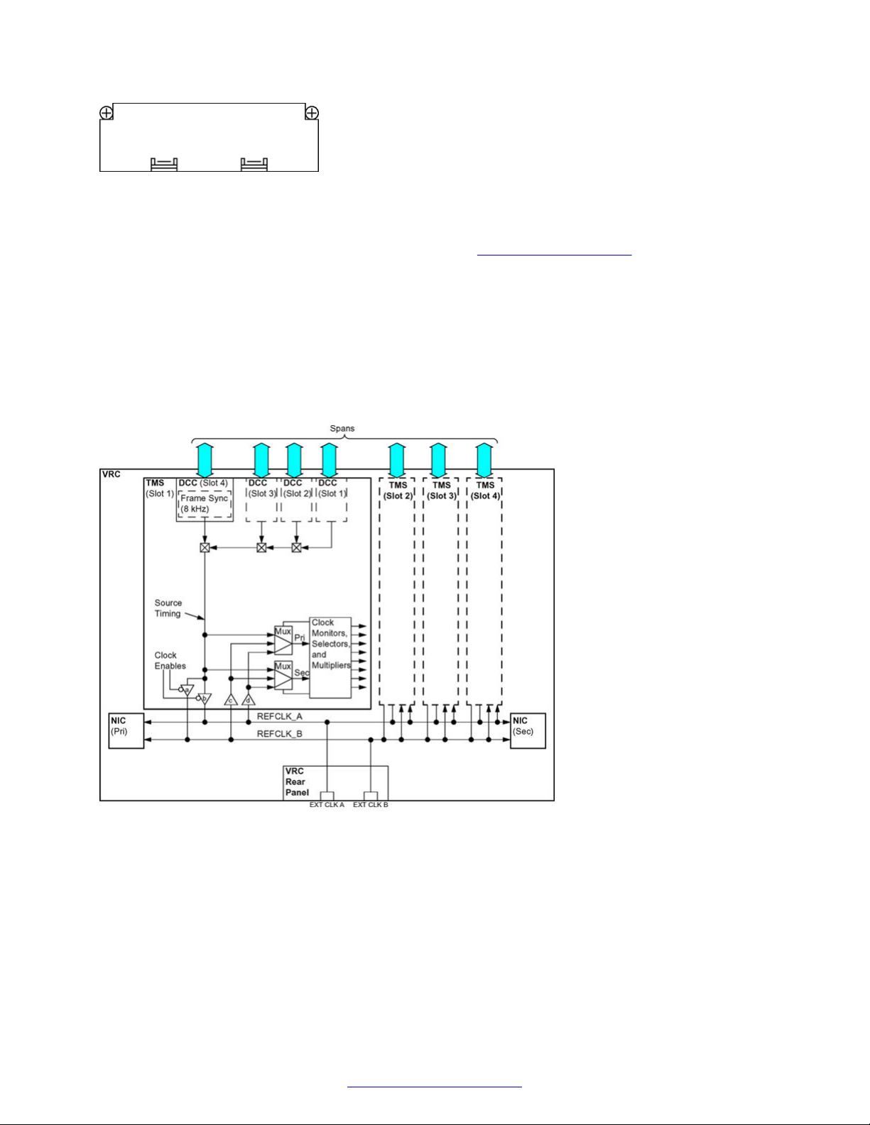
Computer Telephony Bus Clocking
Voice and audio data is transmitted throughout the MPS 1000 over a synchronized Computer
Telephony (CT) bus system.
Figure 11: CT bus System Schematic
Dual redundancy for the CT bus is provided externally to the TMS. Conversation bridging across
multiple chassis is over a fiber optic link, (155Mb, ATM layer 1) provided (optionally) by the NIC
2000. This type of bridging is limited to a two-chassis environment. Systems larger than two VRCs
require the addition of one or more external Asynchronous Transfer Mode (ATM) switches. DualRedundant systems need two external ATM switches.
Any DCC on the node can be configured as the source of either REFCLK_A or REFCLK_B. The
local reference oscillator on any TMS can be used for either reference clock.
20 Avaya Media Processing Server 1000 Hardware Installation and Maintenance October 2014
Comments? infodev@avaya.com
VRC Rear Panel
Multiple sources can be specified for both REFCLK_A and REFCLK_B in the synclist section of the
TMS.cfg file. Clock monitoring and selection provides several prioritized layers of redundancy so
that even multiple failures are compensated for by switching to other clock sources.
The VRC rear panel has two BNC connectors (EXT CLK A and EXT CLK B) for connecting to
external timing sources.
Caution:
These connections are for proprietary use by Avaya personnel only. Do not connect to these
BNC connectors.
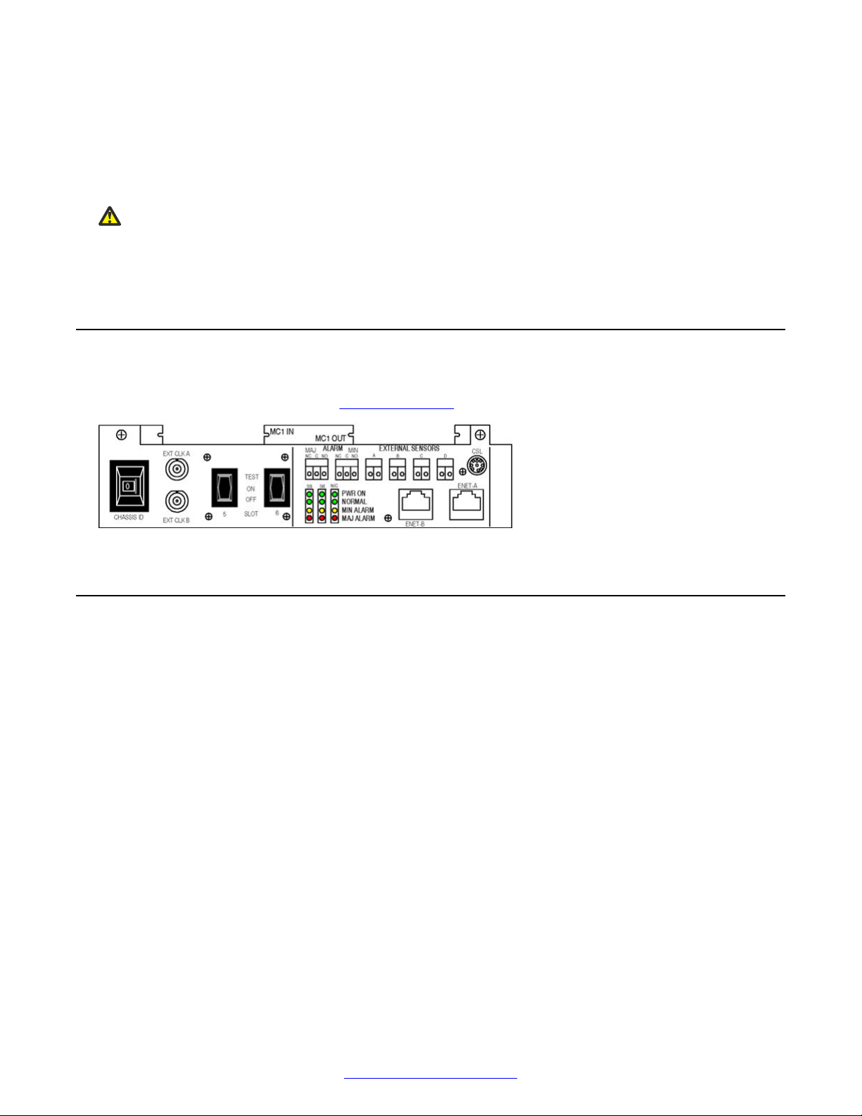
VRC Rear Panel
The VRC rear panel contains controls, indicators, and connectors that are mainly used for
maintenance and diagnostics. See VRC Rear Panel on page 163.
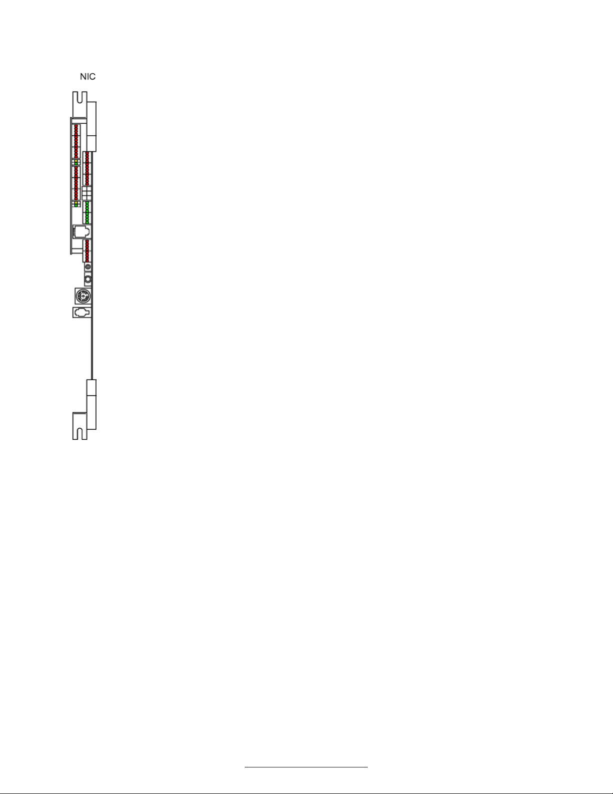
Network Interface Controller
Each VRC in the system can contain one or two NICs (primary and secondary). If two NICs are
used in the chassis, a midplane board is installed over the backplane connector of the NIC slot. The
midplane effectively splits the slot, providing separate connectors for each NIC. The two connectors
on the midplane board are logically assigned slots 7 (primary) and 8 (secondary) for addressing.
October 2014 Avaya Media Processing Server 1000 Hardware Installation and Maintenance 21
Comments? infodev@avaya.com
MPS 1000 System Hardware Overview
Time Space Switch
Each NIC contains a time space switch for the redundant Pulse Code Modulation (PCM) highways.
With all four TMS in the chassis connected to a common CT bus, all lines can be bridged on a
nonblocking basis. The single PCM port for each TMS and single set of PCM highways is split to
both NICs. If a fault occurs in the primary switch, the secondary takes over. Primary and secondary
operation of the Ethernet and PCM highways are independent.
Ethernet Hub/Switch
Because the NICs are identical (that is, they can be installed in either slot), there is a hub for both
ENET A and ENET B on each. However, the primary NIC (installed in slot 7) always controls ENET
A and the secondary NIC (installed in slot 8) controls ENET B. One port of each NIC hub is
connected to a VRC rear panel data connector to provide connection to an external cabinet
switching hub so that multiple chassis can be networked.
Optical ATM Interface
Each NIC also provides a fiber optic ATM interface for connecting the PCM highways to an external
ATM switching fabric, if so configured.
22 Avaya Media Processing Server 1000 Hardware Installation and Maintenance October 2014
Comments? infodev@avaya.com
VRC Power Supplies
VRC Power Supplies
Each slot in the VRC has a separate dedicated power supply. The power supplies are identical and
can be installed in any of the six slots. The slot that each power supply is associated with is
indicated on the decals on the drive bay doors. The output of each power supply is provided to the
respective module slots by the power bus on the VRC backplane.
The Power Supply LEDs are illuminated when sensors on the NIC determine that the individual
voltages are within tolerance. In systems where a NIC is not present, these LEDs are not
illuminated.
The NIC slot has not dedicated power supply. If any slot (1-6) has power applied (that is, the
corresponding slot power supply is installed and slot power is on), the NIC slot receives power. The
NIC has a momentary reset button that removes and reapplies power to the board when the button
is pressed and released. A soft reset can also be performed on the NIC at the command line. See
Resetting the NIC on page 147.
October 2014 Avaya Media Processing Server 1000 Hardware Installation and Maintenance 23
Comments? infodev@avaya.com
MPS 1000 System Hardware Overview
Standalone MPS 500
A standalone MPS 500 can be mounted in 43 RU 48 RU cabinets. For MPS 500 documentation,
see the document MPS 500 Hardware Installation and Maintenance (NN44100-302).
Application or Speech Processors
The Application or Speech Server platform is an expandable server platform designed to provide a
range of services that include various forms of Speech Recognition Speech Verification and Text-toSpeech.
The Application or Speech Server platform consists of a cluster of high-performance processors that
are fully integrated with the MPS 1000. These processors can provide a completely fault-tolerant
environment, that includes redundant networking and storage capacity. A total of 24 processors can
be installed in one cabinet and multiple cabinets can be linked for larger systems.
Application or Speech processors supported in 4.1 are listed in the following table.
Server type Application
Processor
Netra 240 yes no yes 2U server
Server type Application Processor Speech Tools
IBM x3550 yes yes yes
HP DL360 G5 yes yes yes
HP DL360 G7 yes yes yes
Speech Redundant
Ethernet
Notes
IBM xSeries 335
The following diagram shows the IBM x335 Type 8676 server.
24 Avaya Media Processing Server 1000 Hardware Installation and Maintenance October 2014
Comments? infodev@avaya.com
Application or Speech Processors
Refer to the online Installation Guide for the IBM x335 at http://www.ibm.com
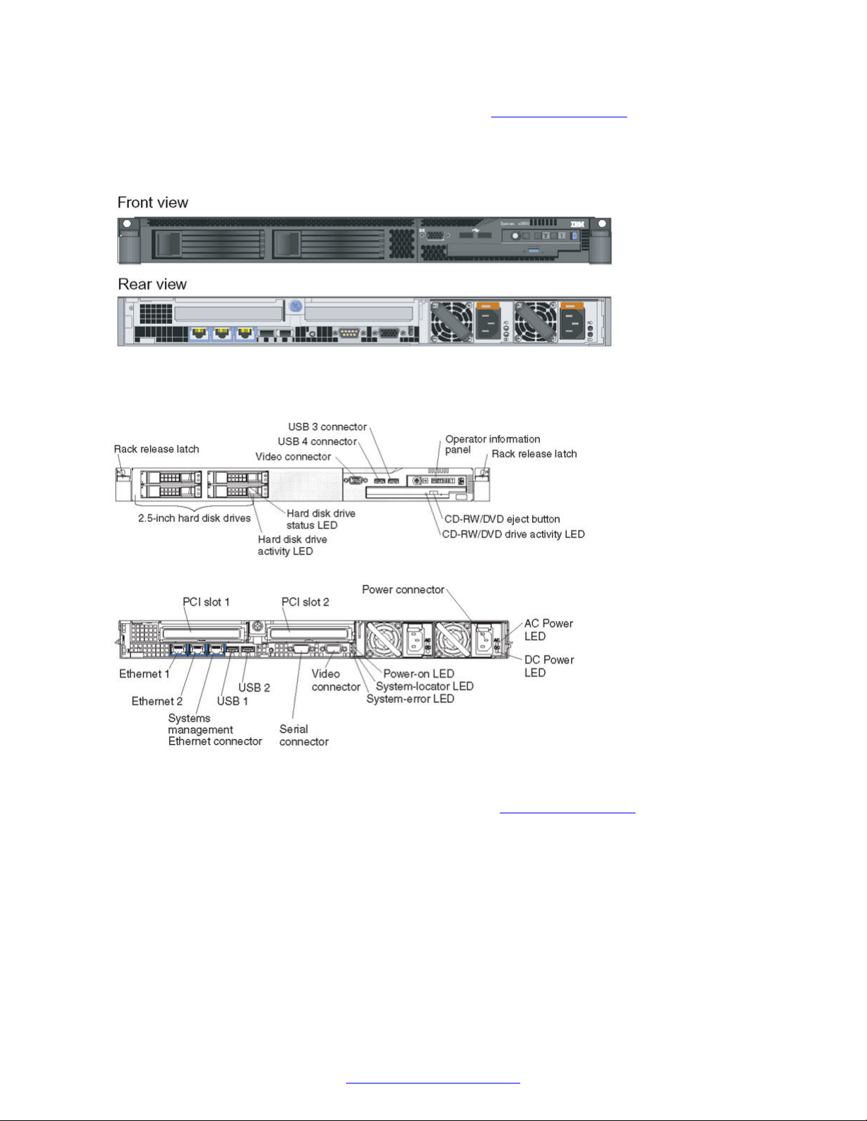
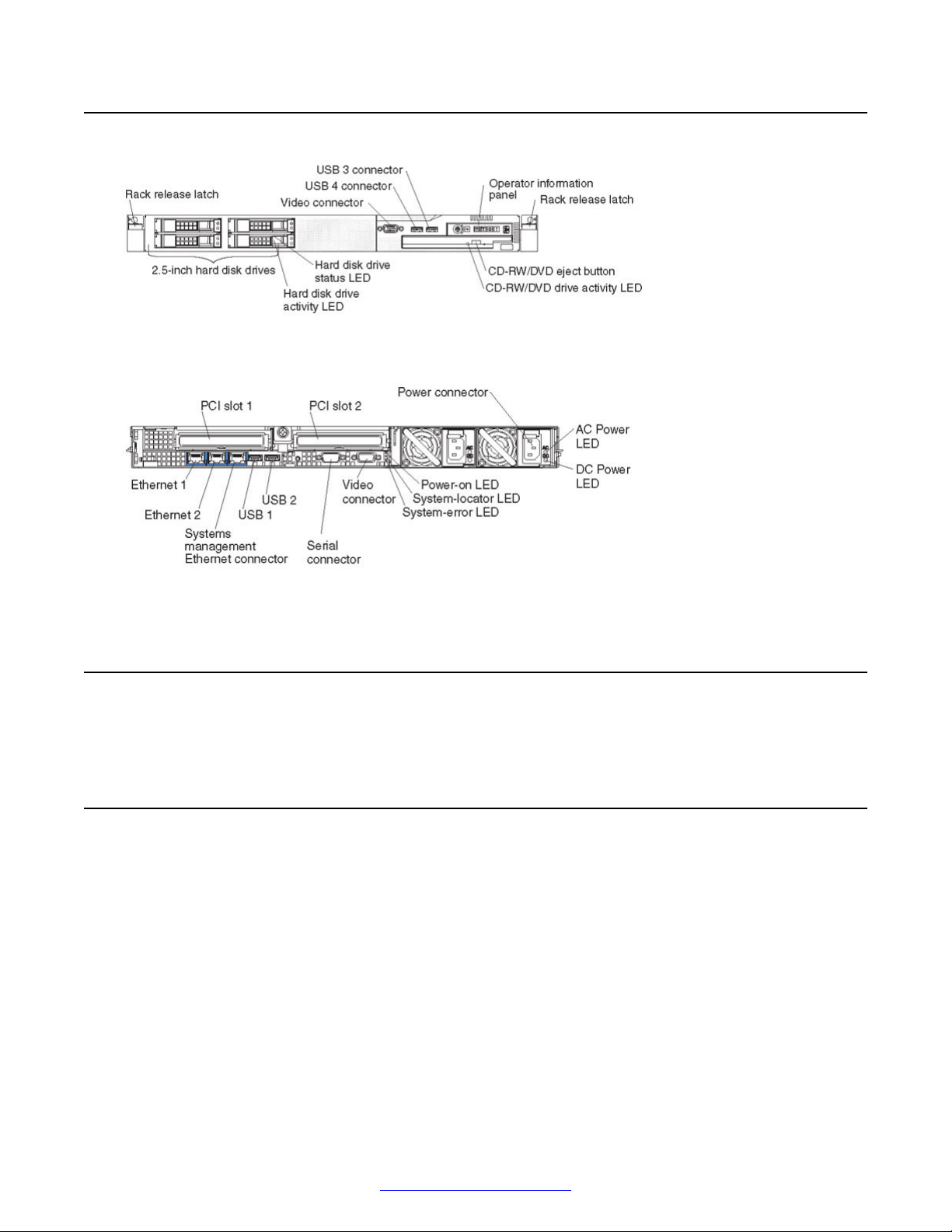
IBM x3550
The following diagrams show the front and rear view of the IBM x3550 type 7978 server.
Figure 12: Model A
Figure 13: Model B
Refer to the online Installation Guide for the IBM x3550 at
http://www.ibm.com
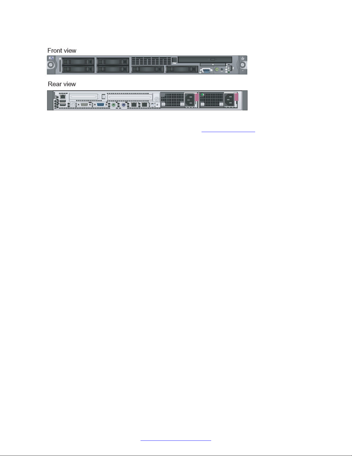
HP DL360 G5 Speech Server
The following diagram shows the HP ProLiant DL360 Generation 5p (G5p).
October 2014 Avaya Media Processing Server 1000 Hardware Installation and Maintenance 25
Comments? infodev@avaya.com
MPS 1000 System Hardware Overview
Refer to the online Installation Guide for the DL360 G5 at http://www.hp.com/
HP DL360 G7 Speech Server
The following diagram shows the HP DL360 G7 Speech Server.
26 Avaya Media Processing Server 1000 Hardware Installation and Maintenance October 2014
Comments? infodev@avaya.com
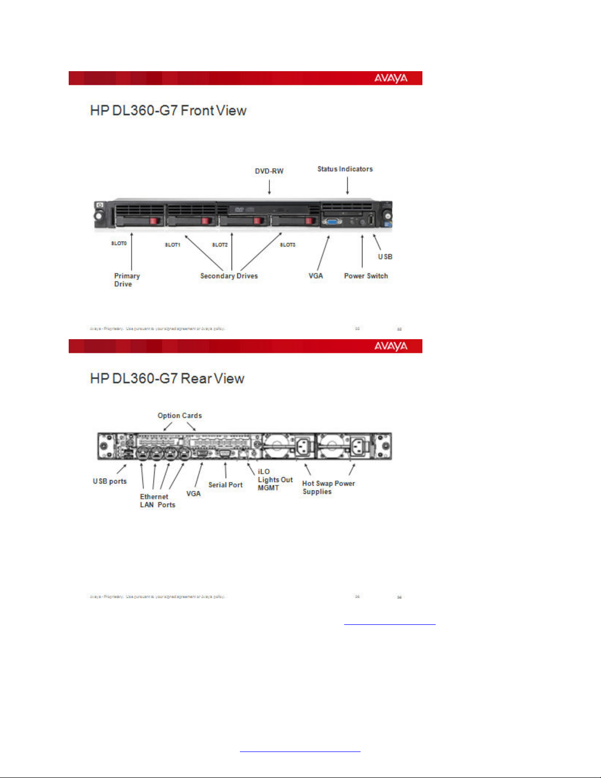
Application or Speech Processors
Refer to the online Installation Guide for the DL360 G7 at http://www.hp.com/
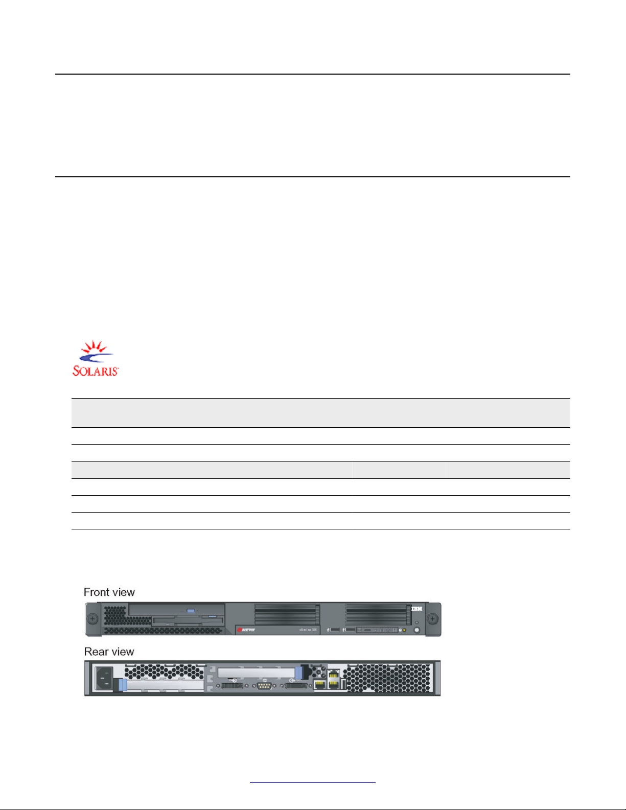
SPARC-Based Servers
Supports the following Oracle server models via Solaris 2.10:
• V Series (V215, V245)
October 2014 Avaya Media Processing Server 1000 Hardware Installation and Maintenance 27
Comments? infodev@avaya.com

MPS 1000 System Hardware Overview
• T Series (T2000, T5120, T5220, T4-1)
• Netra 240
The following diagram shows Netra T4–1 Server.
Terminal Server (Optional)
The optional terminal server provides remote access for servers that have Lights Out Management
(LOM) capability. LOM capability is a service requirement and is accomplished through the use of a
terminal server or a VPN.
The Terminal Server can be configured to provide Telnet port access remote access to any of the
application or speech processors connected to the server.
Figure 14: Terminal Server Rear View
28 Avaya Media Processing Server 1000 Hardware Installation and Maintenance October 2014
Comments? infodev@avaya.com
MPS 1000 Processor Layout
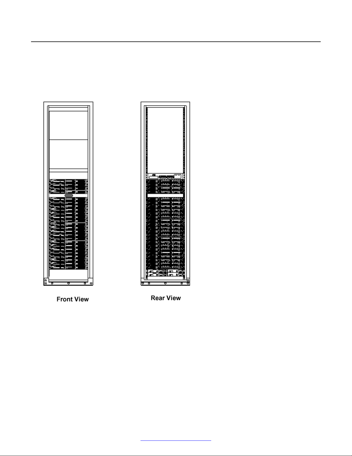
MPS 1000 Processor Layout
A typical Processor cabinet with 24 servers, one BPS-2000, and four AC Power Distribution Units
(PDU) is shown in the following diagram.
The Cabinet is the standard 84" Avaya cabinet. The Power Distribution Units (PDU) are especially
designed for the rack mounted servers and require special AC line cords.
Figure 15: MPS Processor Cabinets
October 2014 Avaya Media Processing Server 1000 Hardware Installation and Maintenance 29
Comments? infodev@avaya.com
MPS 1000 System Hardware Overview
Speech Server Controls and Indicators
Figure 16: IBM x3550 Front Panel
Figure 17: IBM x3550 Rear Panel
Power Distribution Unit
The following section documents the power distribution unit for the MPS 1000.
AC Power Distribution Unit
The AC power distribution panels provide connectivity between cabinet based items and the main
power. Avaya offers two types of AC power; front end power distribution units (FE PDU) and back
end power distribution units (BE PDU). The following sections describe these PDU.
FE PDU
The following diagram shows the front and rear views of two FE PDU.
30 Avaya Media Processing Server 1000 Hardware Installation and Maintenance October 2014
Comments? infodev@avaya.com
 Loading...