

Page 1

BCM450 Rls 6.0
Media Bay Modules
Task Based Guide
Page 2

Media Bay Modules
Copyright © 2010 Avaya Inc.
All Rights Reserved.
Notices
While reasonable efforts have been made to ensure that the information in this document is complete and accurate
at the time of printing, Avaya assumes no liability for any errors. Avaya reserves the right to make changes and
corrections to the information in this document without the obligation to notify any person or organization of such
changes.
Documentation disclaimer
Avaya shall not be responsible for any modifications, additions, or deletions to the original published version of
this documentation unless such modifications, additions, or deletions were performed by Avaya. End User agree to
indemnify and hold harmless Avaya, Avaya’s agents, servants and employees against all claims, lawsuits, demands
and judgments arising out of, or in connection with, subsequent modifications, additions or deletions to this
documentation, to the extent made by End User.
Link disclaimer
Avaya is not responsible for the contents or reliability of any linked Web sites referenced within this site or
documentation(s) provided by Avaya. Avaya is not responsible for the accuracy of any information, statement or
content provided on these sites and does not necessarily endorse the products, services, or information described or
offered within them. Avaya does not guarantee that these links will work all the time and has no control over the
availability of the linked pages.
Warranty
Avaya provides a limited warranty on this product. Refer to your sales agreement to establish the terms of the
limited warranty. In addition, Avaya’s standard warranty language, as well as information regarding support for
this product, while under warranty, is available to Avaya customers and other parties through the Avaya Support
Web site: http://www.avaya.com/support
Please note that if you acquired the product from an authorized reseller, the warranty is provided to you by said
reseller and not by Avaya.
Licenses
THE SOFTWARE LICENSE TERMS AVAILABLE ON THE AVAYA WEBSITE,
HTTP://SUPPORT.AVAYA.COM/LICENSEINFO/ ARE APPLICABLE TO ANYONE WHO DOWNLOADS,
USES AND/OR INSTALLS AVAYA SOFTWARE, PURCHASED FROM AVAYA INC., ANY AVAYA
AFFILIATE, OR AN AUTHORIZED AVAYA RESELLER (AS APPLICABLE) UNDER A COMMERCIAL
AGREEMENT WITH AVAYA OR AN AUTHORIZED AVAYA RESELLER. UNLESS OTHERWISE
AGREED TO BY AVAYA IN WRITING, AVAYA DOES NOT EXTEND THIS LICENSE IF THE
SOFTWARE WAS OBTAINED FROM ANYONE OTHER THAN AVAYA, AN AVAYA AFFILIATE OR AN
AVAYA AUTHORIZED RESELLER, AND AVAYA RESERVES THE RIGHT TO TAKE LEGAL ACTION
AGAINST YOU AND ANYONE ELSE USING OR SELLING THE SOFTWARE WITHOUT A LICENSE. BY
INSTALLING, DOWNLOADING OR USING THE SOFTWARE, OR AUTHORIZING OTHERS TO DO SO,
YOU, ON BEHALF OF YOURSELF AND THE ENTITY FOR WHOM YOU ARE INSTALLING,
DOWNLOADING OR USING THE SOFTWARE (HEREINAFTER REFERRED TO INTERCHANGEABLY
AS "YOU" AND "END USER"), AGREE TO THESE TERMS AND CONDITIONS AND CREATE A
BINDING CONTRACT BETWEEN YOU AND AVAYA INC. OR THE APPLICABLE AVAYA AFFILIATE
("AVAYA").
Copyright
Except where expressly stated otherwise, no use should be made of the Documentation(s) and Product(s) provided
by Avaya. All content in this documentation(s) and the product(s) provided by Avaya including the selection,
arrangement and design of the content is owned either by Avaya or its licensors and is protected by copyright and
other intellectual property laws including the sui generis rights relating to the protection of databases. You may not
modify, copy, reproduce, republish, upload, post, transmit or distribute in any way any content, in whole or in part,
including any code and software. Unauthorized reproduction, transmission, dissemination, storage, and or use
without the express written consent of Avaya can be a criminal, as well as a civil offense under the applicable law.
Third Party Components
Certain software programs or portions thereof included in the Product may contain software distributed under third
party agreements ("Third Party Components"), which may contain terms that expand or limit rights to use certain
portions of the Product ("Third Party Terms"). Information regarding distributed Linux OS source code (for those
Products that have distributed the Linux OS source code), and identifying the copyright holders of the Third Party
Components and the Third Party Terms that apply to them is available on the Avaya Support Web site:
http://support.avaya.com/Copyright.
Trademarks
The trademarks, logos and service marks ("Marks") displayed in this site, the documentation(s) and product(s)
provided by Avaya are the registered or unregistered Marks of Avaya, its affiliates, or other third parties. Users
are not permitted to use such Marks without prior written consent from Avaya or such third party which may own
the Mark. Nothing contained in this site, the documentation(s) and product(s) should be construed as granting, by
implication, estoppel, or otherwise, any license or right in and to the Marks without the express written permission
of Avaya or the applicable third party. Avaya is a registered trademark of Avaya Inc. All non-Avaya trademarks
are the property of their respective owners.
2 NN40011-003 Issue 1.2 BCM450 Rls 6.0
Page 3

Media Bay Modules
Downloading documents
For the most current versions of documentation, see the Avaya Support. Web site: http://www.avaya.com/support
Contact Avaya Support
Avaya provides a telephone number for you to use to report problems or to ask questions about your product. The
support telephone number is 1-800-242-2121 in the United States. For additional support telephone numbers, see
the Avaya Web site: http://www.avaya.com/support
Copyright © 2010 ITEL, All Rights Reserved
The copyright in the material belongs to ITEL and no part of the material may
be reproduced in any form without the prior written permission of a duly
authorised representative of ITEL.
NN40011-003 Issue 1.2 BCM450 Rls 6.0 3
Page 4

Media Bay Modules
Table of Contents
Media Bay Modules ........................................................... 5
Overview .......................................................................................... 5
Required Information ....................................................................... 5
Flow Chart ....................................................................................... 6
Supported Media Bay Modules ........................................................ 7
Media Bay Module Descriptions ........................................................................ 7
Telephony Resources & Media Bay Modules ................................ 13
Main Unit MBM Locations ................................................................................ 14
Expansion Unit MBM Locations ....................................................................... 14
Configuring Media Bay Modules in Telephony Resources .............................. 15
Configuring the Fibre Expansion Module ........................................................ 20
Installing the Media Bay Modules .................................................. 26
MBM’s Requiring Further Dip Switch Configuration ........................................ 28
Additional Information .................................................... 30
Additional MBM Configuration ....................................................... 30
De-configuring Media Bay Modules ................................................................. 30
Disabling/Enabling MBM’s ............................................................................... 32
Media Bay Module Specific Settings .............................................. 34
Trunk Media Bay Modules ............................................................................... 36
DTM-PRI Modules ........................................................................................... 38
DASS2 Modules ............................................................................................... 41
DPNSS Modules .............................................................................................. 42
BRI Module ...................................................................................................... 43
CTM/GATM (4 and 8 port) Module .................................................................. 46
Station Media Bay Modules Types .................................................................. 47
DSM 16/32(+) Modules .................................................................................... 47
ASM Analog Station Module Configuration ..................................................... 48
Combination Modules ...................................................................................... 49
Media Bay Modules Wiring Charts ................................................. 50
ASM8(+)/GASM/DSM(+) Media Bay Module Amphenol Wiring ...................... 50
ADID4/8 Media Bay Module Amphenol Wiring ................................................ 51
GATM4/8 Media Bay Module Amphenol Wiring .............................................. 52
G4/8x16 Media Bay Module Amphenol Wiring ................................................ 53
4x16 Media Bay Module Wiring ....................................................................... 53
BRI Ports .......................................................................................................... 54
DTM Ports ........................................................................................................ 55
Avaya Documentation Links ................................ .......... 56
4 NN40011-003 Issue 1.2 BCM450 Rls 6.0
Page 5

Media Bay Modules
Note: This guide is specific to BCM450 Media Bay Module installation and
configuration. For information concerning BCM50 Media Bay Module
installation and configuration, please refer to the BCM50 Hardware &
Installation Guide and the BCM50 System Start Up Guide.
Media Bay Modules
Overview
Media Bay Modules (MBM’s) provide station (extension) and trunk capability
for the BCM450. Each MBM provides specific station/trunk capability to allow
connection to a variety of trunk types (e.g. analog, ISDN) and stations (e.g.
analog, digital)
Before you install a Media Bay Module, configuration will be required within
the Telephony Resources area of Element Manager to define ―where‖ the
Media Bay Module should be located. This configuration determines which
line numbers (trunks) or DNs (extensions) the equipment connected to the
module will have access to, and what dip switch configuration each MBM will
require.
The BCM450 main unit can support up to 4 MBM’s, whilst the expansion unit
can support up to 6 MBM’s. Therefore, a maximum of 10 MBM’s can be
supported on the BCM450.
Further extension/line expansion can be achieved by using the Fibre
Expansion Module to connect up to 6 legacy Norstar Expansion Modules.
However, the BCM450 maximum capacity limits of 300 extensions and 130
trunks (with Capacity Expansion Card) still apply.
Note: If the station and or trunk requirements of the BCM450 are such that an
expansion unit will be required, then the expansion unit will need to be
enabled by a keycode.
Required Information
Before installing the Media Bay Modules, you should consider the following to
help define the requirements for each module:
Determine the type and number of Media Bay Modules
Decide whether each MBM should be in the main or expansion unit
NN40011-003 Issue 1.2 BCM450 Rls 6.0 5
Page 6
Media Bay Modules
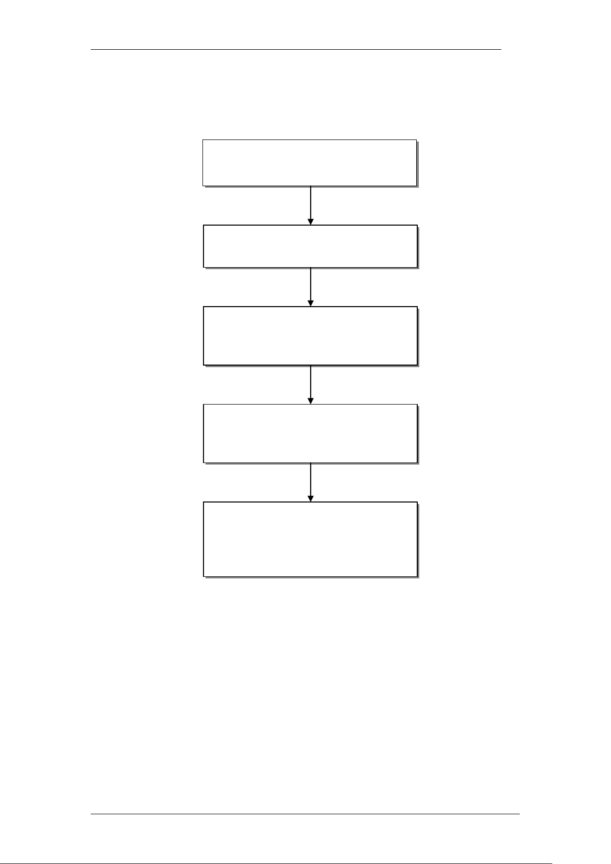
Plan the types and number of Media
Bay Modules required for the
installation
Plan the installation location of each
MBM, i.e. main or expansion unit.
Prepare the BCM for Media Bay
Modules: refer to the Configuring
Media Bay Modules in Telephony
Resources section of this guide.
Install the MBM’s in the BCM main or
expansion units: refer to the Installing
the Media Bay Modules section of
this guide.
It may be necessary to further
configure the MBM’s with specific
settings: refer to the Media Bay
Module Specific Settings section of
this guide.
Flow Chart
Use this flow chart to configure and install the Media Bay Modules:
6 NN40011-003 Issue 1.2 BCM450 Rls 6.0
Page 7

Media Bay Modules
Supported Media Bay Modules
The following Media Bay Modules are supported on the BCM450:
Digital Trunk Modules:
o DTM (digital trunk module)
o BRI (ISDN Basic Rate trunk module)
Analog Trunk Modules
o CTM4/8 (4/8-port analog CLID trunk module)
o GATM4/8 (global 4/8-port analog trunk module)
o ADID4/8 (4/8-port analog direct inward dial)
Digital Station Modules
o DSM16(+)/32(+) (16/32-port digital station module)
Analog Station Modules
o ASM8/8+ (8-port analog station interface)
o GASM8 (global 8-port analog station interface)
Combination Modules
o 4/8x16 Combo (4/8 analog trunks, 16 digital stations,
combination of CTM4/8 & DSM16)
o G4/8x16 Combo (global 4/8 analog trunks, 16 digital stations,
combination of GATM4/8 & DSM16)
Special Modules
o FEM (Fibre Expansion Module, connects legacy Norstar
expansion modules to the BCM)
o R2MFC
Media Bay Module Descriptions
The following sections describe the hardware attributes and functionality of
the Media Bay Modules.
Digital Trunk Modules
When configured on a North American BCM system, the DTM connects a T1
or PRI circuit to the BCM system; T1 circuits provide 24 digital channels to the
PSTN, while PRI circuits provide 23 digital channels to the PSTN.
When configured on an International BCM system, the DTM connects an ETSI
ISDN (E1) or PRI (E1) circuit to the BCM system, providing a maximum of 30
digital channels to the PSTN.
The DTM module supports the following protocols:
PRI
DASS2
DPNSS
NN40011-003 Issue 1.2 BCM450 Rls 6.0 7
Page 8
Media Bay Modules
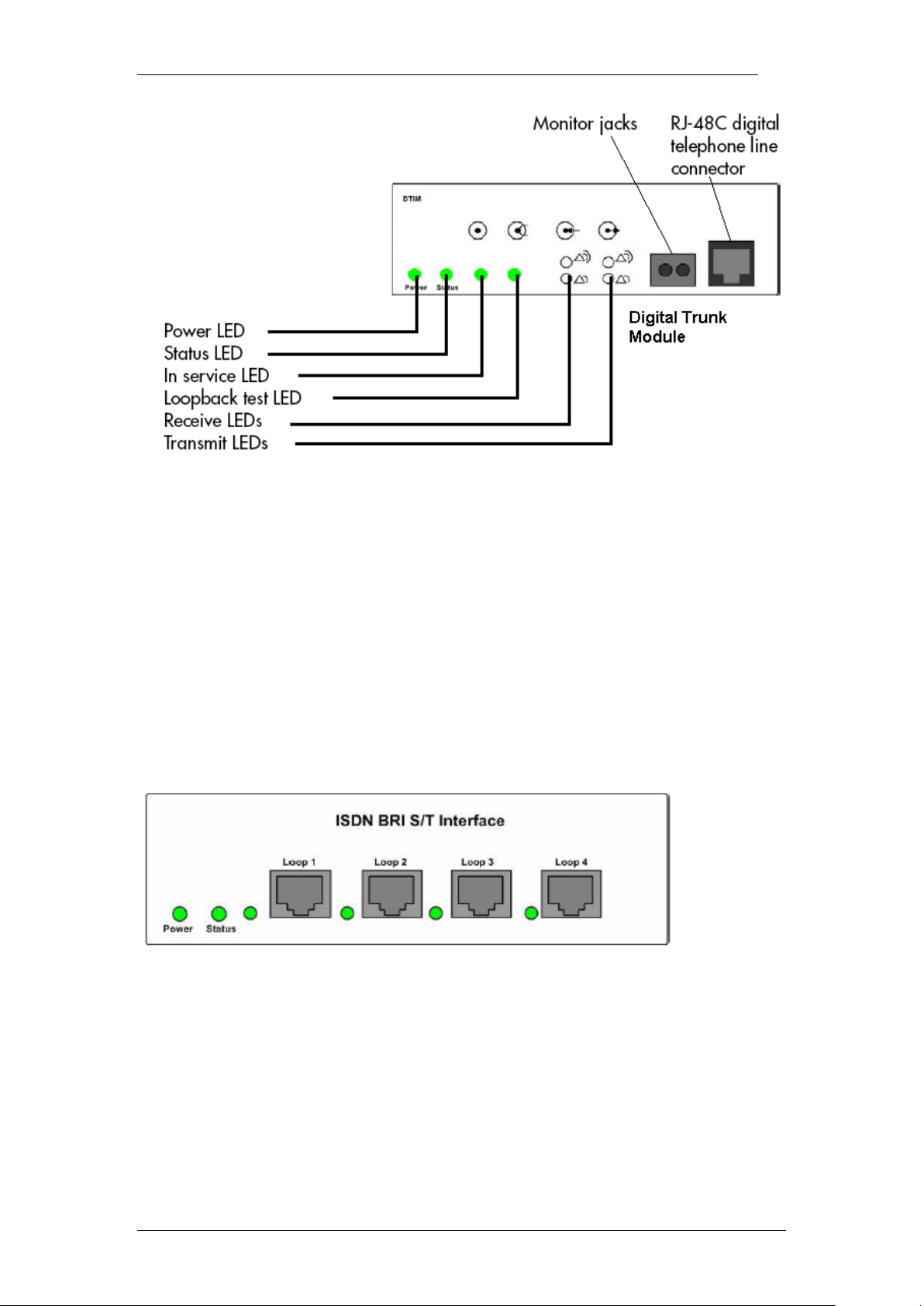
Basic Rate Interface Media Bay Module
The Basic Rate Interface Media Bay Module (BRIM) connects a maximum of
four BRI ISDN loops to the BCM system. Each ISDN loop supports 2
channels.
The BRIM only recognizes the T-interface used in European networks. To use
the BRIM with the U-interface, typical in North American networks, you require
an external NT1 box to convert the U-interface to a T-interface.
Each BRI ISDN connected loop adds two telephone lines to the BCM system.
Each BRIM can add a maximum of eight lines to the BCM system through the
four RJ-48C jacks on the faceplate.
8 NN40011-003 Issue 1.2 BCM450 Rls 6.0
Page 9
Media Bay Modules
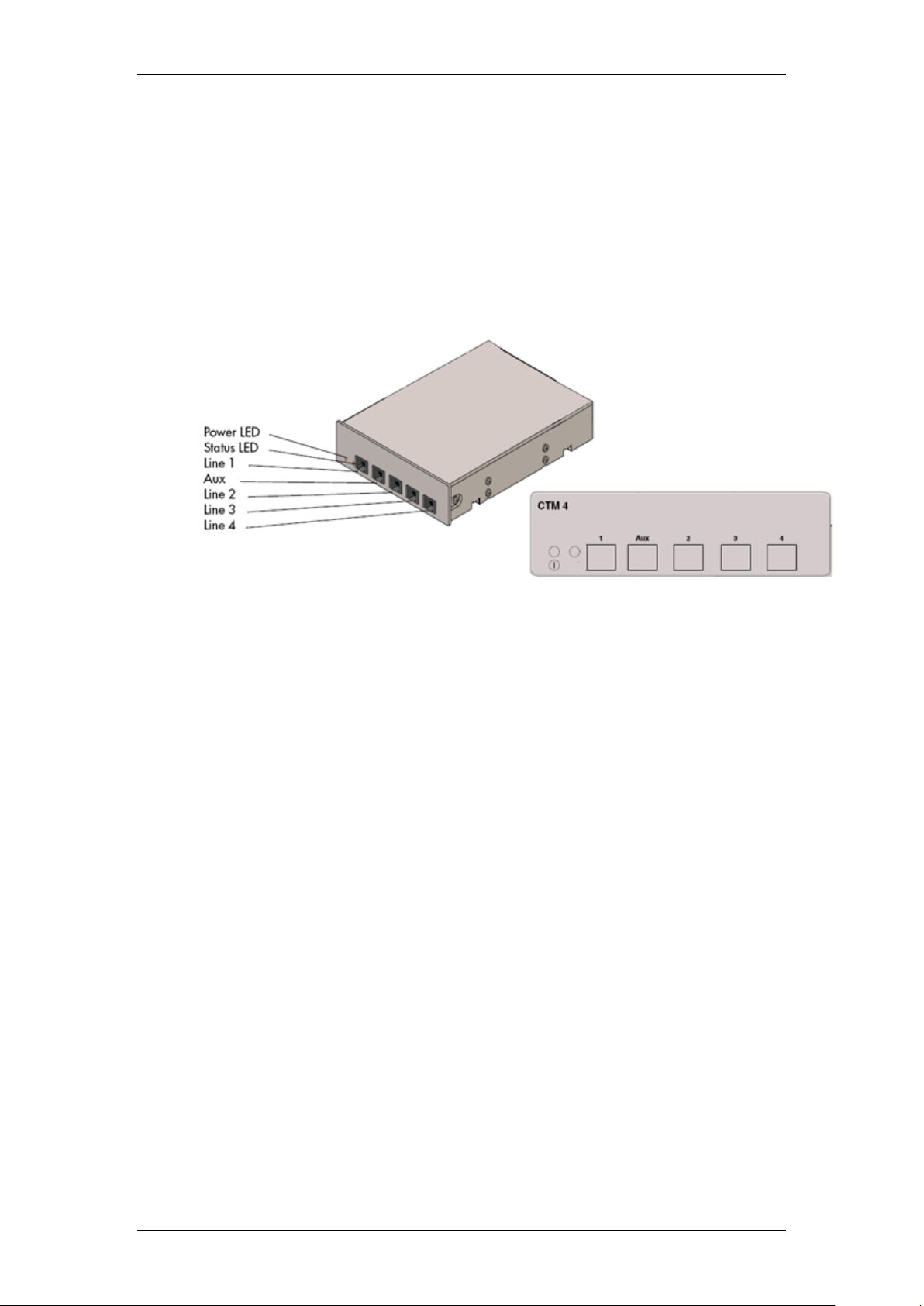
Caller ID Trunk Media Bay Module
There are two types of Caller ID trunk media bay modules (CTM):
1. CTM4:
The CTM4 connects a maximum of four analog calling line ID (CLID)
interfaces to the BCM system through four RJ-11 jacks on the front
faceplate of the MBM. These jacks are labelled Line 1,Auxiliary, Line
2, Line 3, and Line 4. The auxiliary jack connects to Line 1.
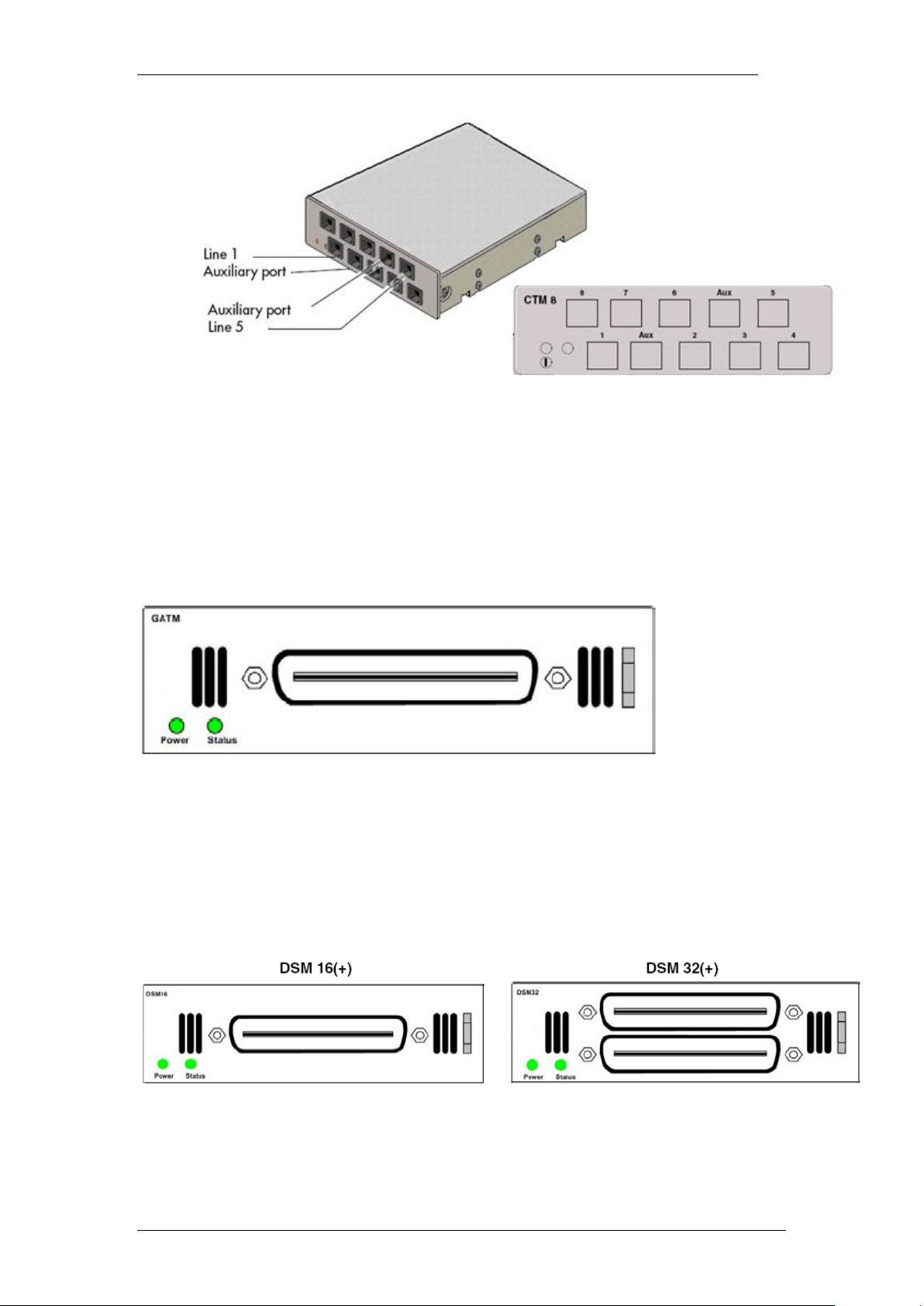
2. CTM8:
The CTM8 provides eight analog CLID interfaces to the BCM system
through eight RJ-11 jacks on the front faceplate of the BCM. Each jack
also supports disconnect supervision. There are two auxiliary jacks on
this MBM which connect to Line 1 and Line 5.
The auxiliary ports will interface to a V.92 or V.90 modem, fax machine
unit, or analog telephone. When the auxiliary device is active, the BCM
system disables the associated line. If the line is active, the auxiliary
port line is disabled.
When an analog telephone is connected to the auxiliary port, it can be
used as an emergency telephone because this line remains active
during a power outage.
NN40011-003 Issue 1.2 BCM450 Rls 6.0 9
Page 10
Media Bay Modules
Global Analog Trunk Media Bay Module
The Global Analog Trunk Media Bay Module (GATM) provides an interface for
four or eight analog public switched telephone network (PSTN) lines. The
GATM supports bothpulse and tone dialing, as well as caller ID and
disconnect supervision in selected markets throughout the world.
The GATM uses an RJ-21 connector as the trunk interface.
Digital Station Media Bay Module
The Digital Station Media Bay Modules (DSM) support digital telephones on
the BCM system.
DSM16(+): supports 16 digital telephones through one RJ-21 connector.
DSM32(+): supports 32 digital telephones through two RJ-21 connectors.
10 NN40011-003 Issue 1.2 BCM450 Rls 6.0
Page 11
Media Bay Modules
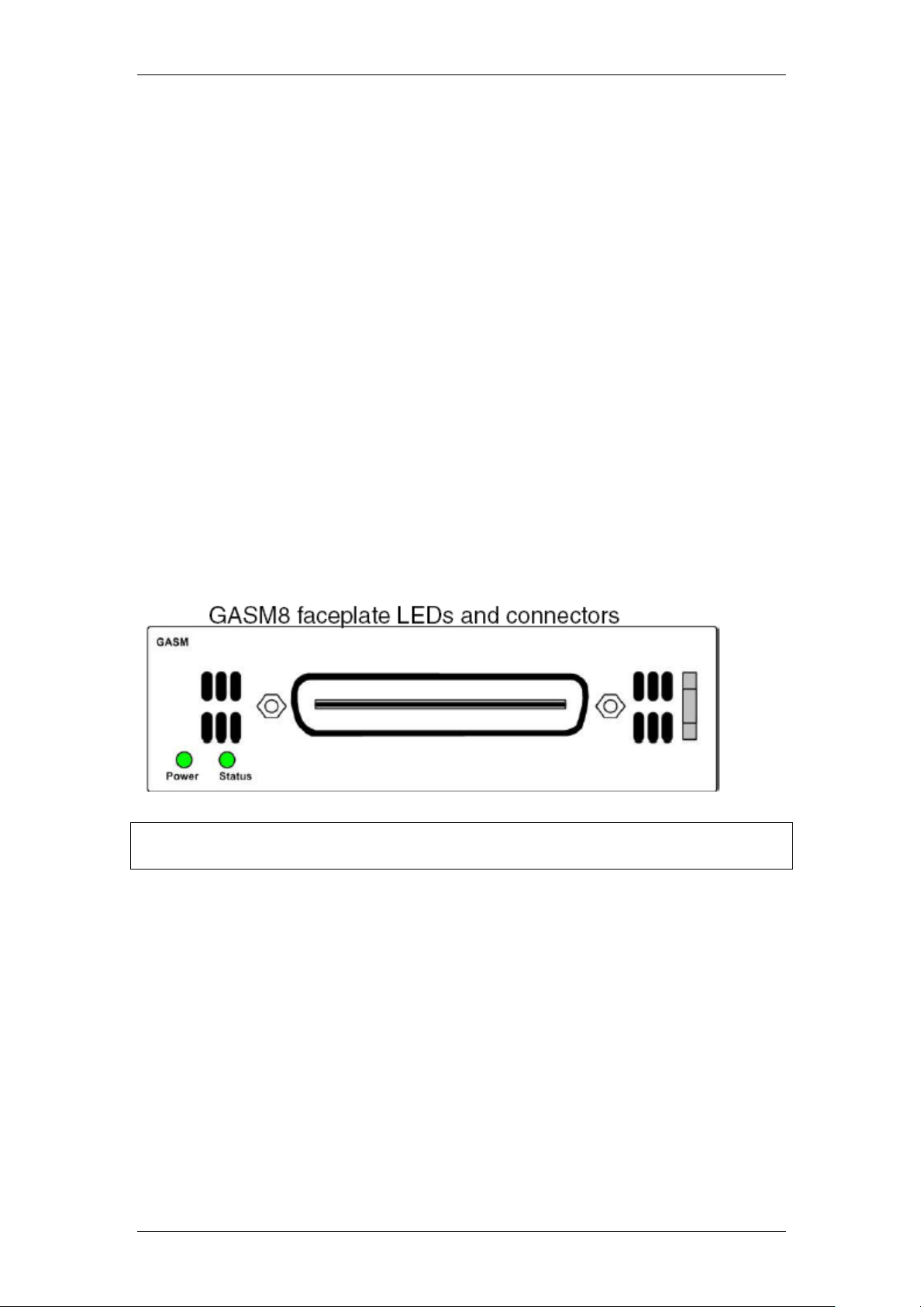
Analog Station Media Bay Modules
The Analog Station Media Bay Modules (ASM, ASM8, ASM8+, and GASM8)
can connect to a maximum of eight analog telecommunication devices. These
devices are standard analog telephones, cordless telephones, fax machines,
answering machines, or modems.
In addition to ASM8 features, the ASM8+ and GASM8 offer the following
features:
Visual Message Waiting Indicator (VMWI) — LED indicates that a
message is waiting.
Disconnect supervision (Open Switch Interval [OSI] as per EIA/TIA
464). Indicates to the attached device, in an established
communication, that the connected device should release the call
Caller ID — provides the name, phone number, and other information
about the caller to the end user telephone at the start of the call.
Firmware downloading capability — allows the system to upgrade the
ASM8+ and GASM8 firmware.
Enhanced ringing capability — ASM8+ and GASM8 provide a ringing
voltage of 2 REN/65 V rms per port.
Calling line identification (CLID)
The GASM8 is designated as an ONS (on-premise station) port.
Note: Due to power constraints, a maximum of 2 GASM MBM’s are supported
in the main unit. Up to 4 GASM units can be installed in the expansion unit.
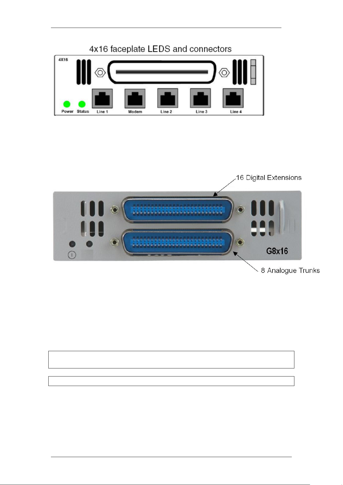
4x16 Media Bay Module
The 4x16 MBM provides both analog trunk and digital telephone connections.
The 4x16 MBM provides connections for four analog lines and 16 digital
telephones. Each of the four analog lines support caller ID and disconnect
supervision. An auxiliary port next to the Line 1 port enables you to use an
analog telephony device, such as a modem, fax, or telephone, to share the
trunk.
NN40011-003 Issue 1.2 BCM450 Rls 6.0 11
Page 12
Media Bay Modules
Global 4x16 and Global 8x16 Module
This is a combination module that provides 16 Digital Extensions and either 4
or 8 analog lines (version dependant).
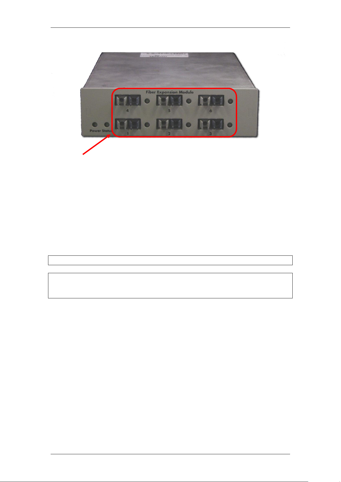
Fibre Expansion Module
The Fibre Expansion Module (FEM) allows legacy Norstar Expansion Modules
(for connecting extensions and trunks) to be connected to the BCM450. This
would be used in installations whereby a Norstar with existing Expansion
Modules was being replaced by the BCM450. The existing Norstar Expansion
Modules would be connected via fibre cables to the fibre ports on the FEM.
Note: The FEM can only be installed in the main unit, not in the expansion
unit.
Note: Only one FEM per main unit is supported.
12 NN40011-003 Issue 1.2 BCM450 Rls 6.0
Page 13
Media Bay Modules
Fibre Ports – Connect to
Norstar Expansion Modules
Up to 6 Norstar Expansion Modules can be connected via fibre cables to the
FEM. Supported Norstar Expansion Modules are:
Global Line Module (Norstar Trunk Module in Element Manager)
Extension Module (Norstar Station Module in Element Manager)
Analog Extension Module (Norstar Analog Station Module in Element
Manager)
Note: Norstar Central Control Unit connection to the FEM is not supported.
Note: ―Daisy chaining‖ of Norstar Analog Extension Modules (AEM) is not
supported on the BCM450, i.e. only one Norstar AEM can be connected to
each FEM fibre port.
Telephony Resources & Media Bay Modules
Media Bay Modules are installed in the BCM450 main and expansion units.
The BCM450 does not auto-detect the MBM type, and therefore configuration
has to take place
BCM450 uses the Dynamic Device Configuration feature, whereby extension
(station) and line numbers can be dynamically configured per MBM.
Therefore, extension and line numbers are not defined by location allocation
within Telephony Resources, as was the case with the BCM200 and BCM400
platforms. Default extension and line numbers exist, but these can be
changed as required.
Telephony Resource allocation is determined differently depending on
whether or not MBM’s will be installed in the BCM450 main unit or the
expansion unit (if utilising):
NN40011-003 Issue 1.2 BCM450 Rls 6.0 13
Page 14
Media Bay Modules
Main Unit: There are 4 Media Bays available, termed MBM1, MBM2,
MBM3, and MBM4. Physical location determines the Telephony
Resources location.
Expansion Unit: There are 6 Media Bays available. Dipswitch
configuration determines the Telephony Resources location. MBM’s
can be installed in any bay in the expansion unit.
Rules concerning MBM locations are greatly simplified resulting in greater
flexibility. Listed below are rules governing the MBM location:
If you are installing a DSM32(+) insert it into MBM slot 1, as this is pre-
configured in Telephony Resources.
FEM modules can only be installed into the main unit.
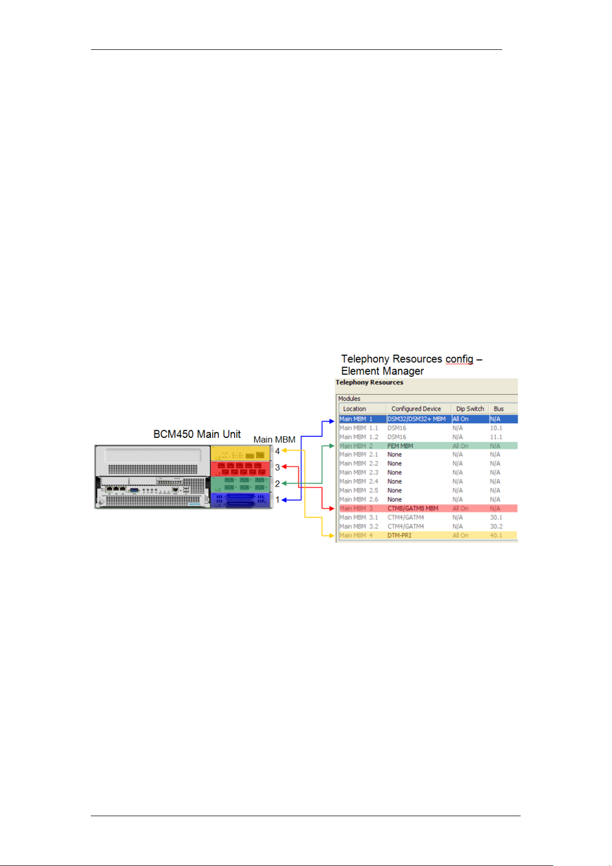
Main Unit MBM Locations
As previously described, the physical location of the MBM’s determines the
Telephony Resource location. There are 4 bays available, which relate to
Telephony Resources locations MBM1 – 4 as below:
Main MBM 1 is pre-configured to be a DSM32(+). This is the only preconfigured module.
Expansion Unit MBM Locations
If more than 4 Media Bay Modules are required to fulfill capacity requirements,
then an expansion unit will be needed. Dipswitches determine which
Telephony Resources location each MBM will use. BCM450 displays what the
dipswitch settings should be for each MBM.
14 NN40011-003 Issue 1.2 BCM450 Rls 6.0
Page 15
Media Bay Modules
An example installation with 6 MBM’s in the expansion unit is shown below.
The Media Bay Modules can be installed in any bay in the expansion unit.
Note: A keycode is required to enable the expansion unit.
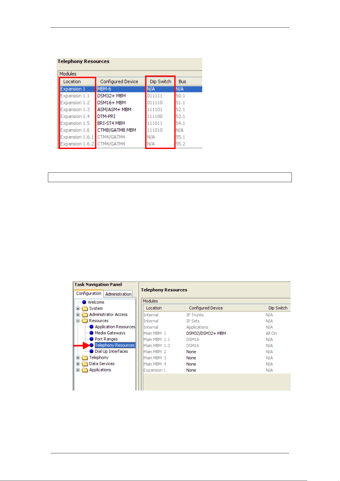
Configuring Media Bay Modules in Telephony Resources
When you have obtained the Media Bay Modules and determined their
locations in either the main or expansion units, the Telephony Resource
configuration can be performed.
1. Launch Element Manager and connect to your BCM450.
2. In the Configuration tab, open the Resources folder and click on
Telephony Resources.
3. The Main MBM 1 location is configured as a DSM32/DSM32+ MBM, as
most installations will use this MBM.
NN40011-003 Issue 1.2 BCM450 Rls 6.0 15
Page 16
Media Bay Modules
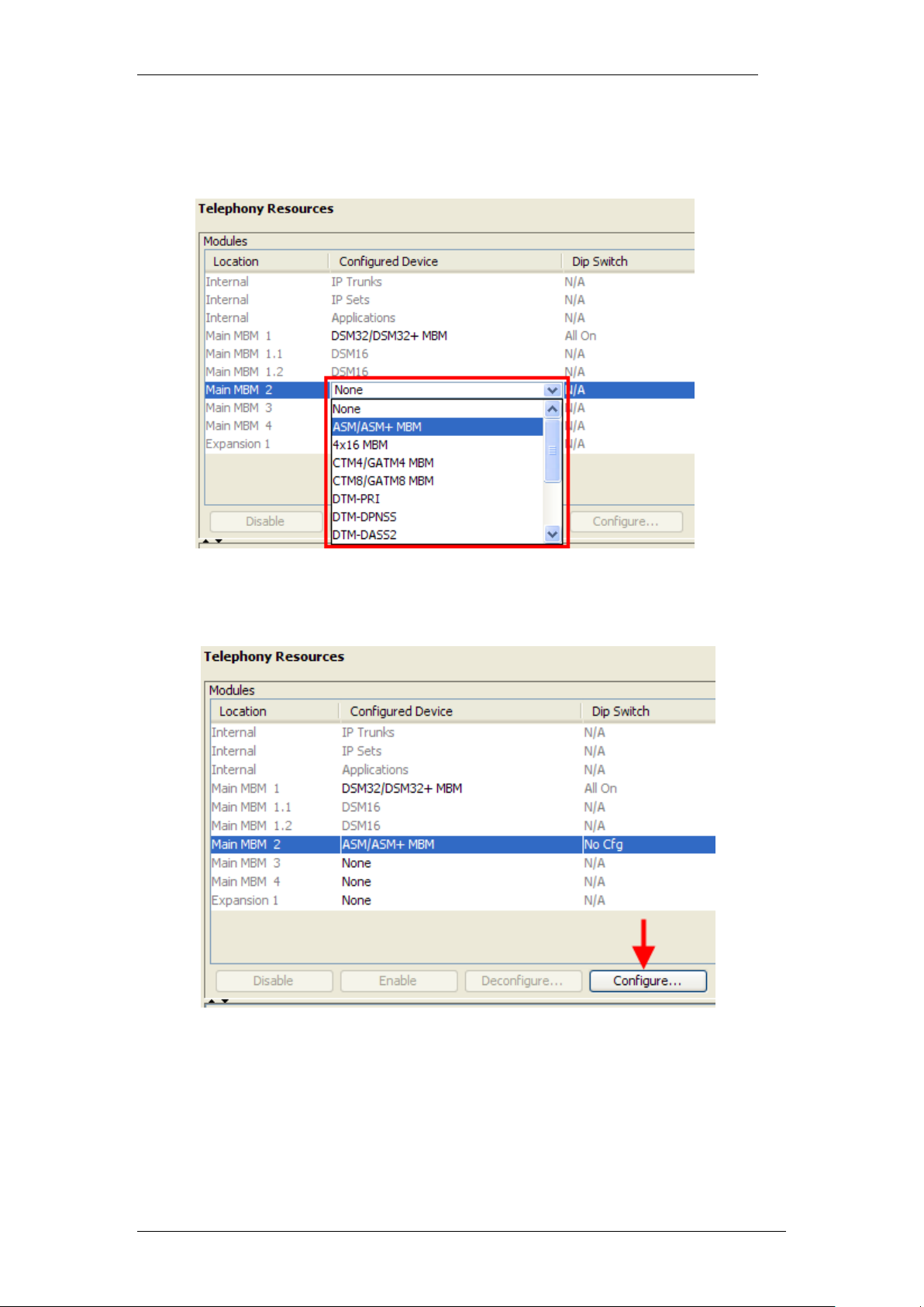
4. Set the other MBM’s to the correct type by double-clicking in the
Configured Device field, and selecting the MBM type to be installed in
the associated bay.
5. When the required MBM type has been selected, the Configure button
becomes active. Click on the Configure button to configure extension
or line allocations to the MBM.
6. The Configure dialog box will appear. You can accept the defaults or
configure new extension (station) or line (trunk) information:
Station Module: Accept the defaults or configure the Start DN,
Public received digits/OLI, and Private received digits/OLI. The
received digits and OLI information will be assigned sequentially to
the number of stations available on that module. There is also the
16 NN40011-003 Issue 1.2 BCM450 Rls 6.0
Page 17
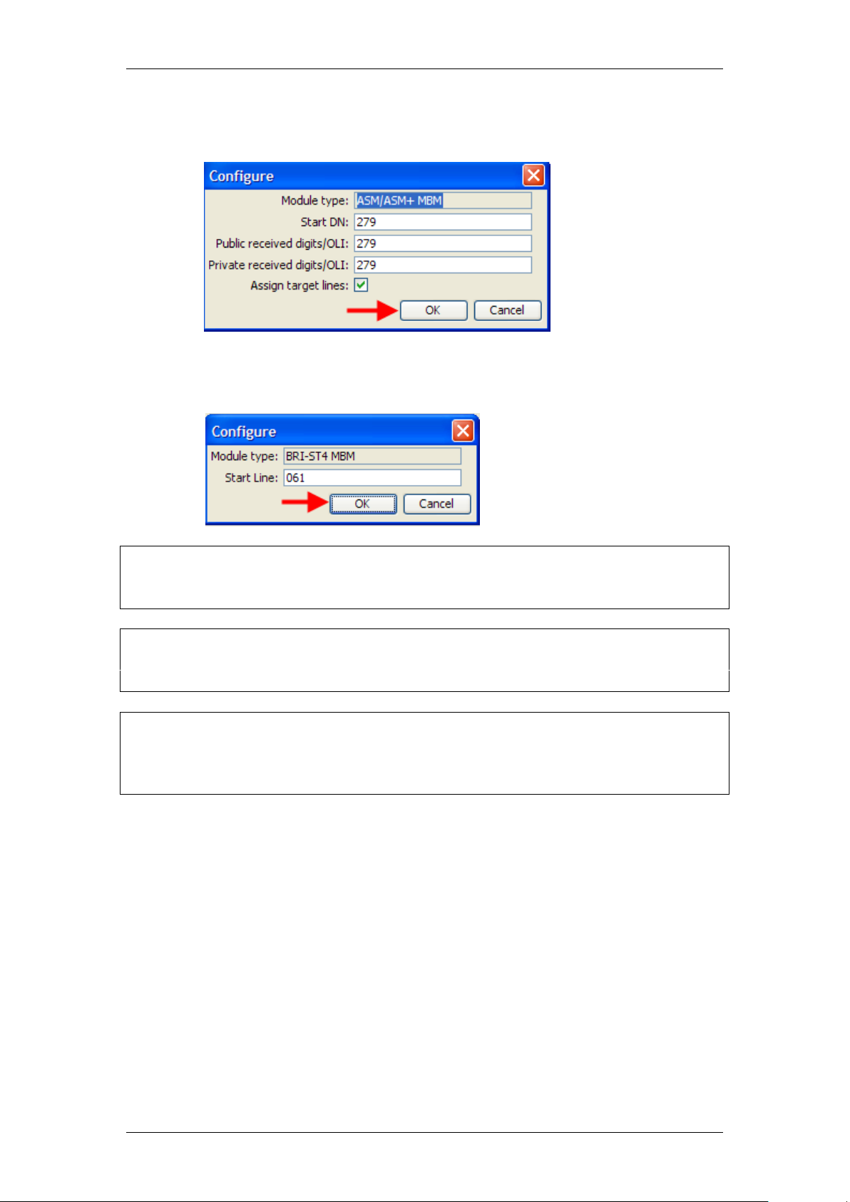
Media Bay Modules
option of assigning Target Lines to the extensions on the MBM. Tick
the Assign target lines check box to do this.
Trunk Module: Accept the default Start Line number or enter a new
starting line number for the trunks presented on the MBM.
Note: There must be enough DN’s available in the system to populate the
entire MBM being configured, otherwise you will not be able to configure the
MBM and it will not function.
Note: There must be enough consecutive line numbers available in the
system to populate the entire MBM being configured, otherwise you will not be
able to configure the MBM and it will not function.
Note: Received Digits and OLI settings can be configured in other areas of
Element Manager, such as Telephony, Active Sets. However, configuring
these settings in Telephony Resources is a convenient and time saving
method, if feasible on your installation.
7. Click on OK when you have entered the required settings.
8. If you are not using the BCM expansion unit in the installation, skip to
step 12 in this section.
NN40011-003 Issue 1.2 BCM450 Rls 6.0 17
Page 18

Media Bay Modules
9. If the BCM expansion unit is being used in this installation, double-click
in the Configured Device field for Expansion 1 and select MBM-6.
10. Configure each MBM as required, as described in steps 4 – 7 in this
section.
11. When configuring each MBM on the expansion unit, 2 extra fields are
displayed (Note and Dip fields) referring to dip switch configuration.
Whilst it is possible to alter the suggested dip switch configuration, it is
recommended to accept the suggested values. The dip switch settings
on the MBM must match the settings in this field.
18 NN40011-003 Issue 1.2 BCM450 Rls 6.0
Page 19

Media Bay Modules
12. You will notice that the required Dip Switch configuration for each
MBM is defined in the Dip Switch column. Note this down for when dip
switch configuration on the MBM is required later in the procedure.
13. Also, the full ranges of extensions or lines for each MBM are listed in
the Low and High columns. This may also be worth noting for
reference purposes.
14. The BCM should now be shut down to allow MBM dip switch
configuration and installation.
Note: Do not install MBM’s whilst the BCM is powered up.
15. Switch to the Administration tab, and navigate to Utilities, Reboot.
16. Click on the Shutdown System button.
NN40011-003 Issue 1.2 BCM450 Rls 6.0 19
Page 20

Media Bay Modules
17. Click OK to shutdown the BCM.
18. An advisory dialog box will display. Click OK to close the box.
19. When the BCM is fully powered down, i.e. the status and power LED’s
are unlit, it will be safe to install the MBM’s. Dip switches should be
configured before installing the MBM’s (refer to the notes made earlier
in step 12). Refer to the Installing the Media Bay Modules section of
this guide.
Configuring the Fibre Expansion Module
The Fibre Expansion Module (FEM) has a slightly different – but not
inconsistent – configuration method. Up to 6 Norstar Expansion Modules can
be connected to the BCM450 via the FEM. Each Norstar Expansion Module
will need to be configured individually in Telephony Resources.
Note: The FEM may only be installed in the BCM main unit. It is not supported
in the expansion unit.
20 NN40011-003 Issue 1.2 BCM450 Rls 6.0
Page 21

Media Bay Modules
The available Configured Device types for the Norstar Expansion Modules
within Telephony Resources are as follows:
Norstar TM (Trunk Module) – Norstar Global Line Module
containing Analog or BRI cards
Norstar SM (Station Module) – Norstar Extension Module,
supporting up to 16 digital extensions
Norstar ASM (Analog Station Module) – Analog Extension Module,
supporting up to 8 Analog extensions (BCM450 does not support
daisy-chaining of Norstar Analog Extension Modules).
Use the following procedure to configure the FEM.
1. Launch Element Manager and connect to your BCM450.
2. In the Configuration tab, open the Resources folder and click on
Telephony Resources.
3. Double-click in the Configured Devices field for the Main MBM slot
corresponding to the location of the FEM. Select FEM MBM from the
drop-down list.
NN40011-003 Issue 1.2 BCM450 Rls 6.0 21
Page 22

Media Bay Modules
4. A further 6 sub-locations will appear, corresponding to the 6 possible
Norstar Expansion Modules that could be connected via the FEM (Main
MBM 2.1–2.6 in the example below).
5. Double-click in the Configured Devices field for each connected
Norstar Expansion Module, and select either Norstar TM, Norstar SM,
or Norstar ASM (refer to the beginning of this section for descriptions).
6. If selecting Norstar TM, the Location column is further expanded to
allow the 3 possible cards in the Norstar Global Line Module to be
configured (Main MBM 2.2.1-2.2.3 in the example below). Double-click
in the corresponding Configured Device field and select the
appropriate line card.
22 NN40011-003 Issue 1.2 BCM450 Rls 6.0
Page 23

Media Bay Modules
7. When the required Norstar Expansion Module type (and line card type
for Norstar TM) has been selected, the Configure button becomes
active. Click on the Configure button to configure extension or line
allocations to the Norstar Expansion Module.
8. The Configure dialog box will appear. You can accept the defaults or
configure new extension (station) or line (trunk) information:
Norstar Station Module: Accept the defaults or configure the Start
DN, Public received digits/OLI, and Private received digits/OLI.
The received digits and OLI information will be assigned
sequentially to the number of stations available on that module.
There is also the option of assigning Target Lines to the extensions
on the MBM. Tick the Assign target lines check box to do this.
NN40011-003 Issue 1.2 BCM450 Rls 6.0 23
Page 24

Media Bay Modules
Norstar Trunk Module: Accept the default Start Line number or
enter a new starting line number for the trunks presented on the
MBM.
Note: There must be enough DN’s available in the system to populate the
entire Norstar Expansion Module being configured, otherwise you will not be
able to configure the module and it will not function.
Note: There must be enough consecutive line numbers available in the
system to populate the entire Norstar Expansion Module being configured,
otherwise you will not be able to configure the module and it will not function.
Note: Received Digits and OLI settings can be configured in other areas of
Element Manager, such as Telephony, Active Sets. However, configuring
these settings in Telephony Resources is a convenient and time saving
method, if feasible on your installation.
9. Click on OK when you have entered the required settings.
10. The FEM dip switches should be set to all On.
11. The full ranges of extensions or lines associated with each Norstar
Extension Module are listed in the Low and High columns. This may
be useful to note for reference purposes.
12. The BCM should now be shut down to allow FEM MBM installation. All
the FEM dip switches should be set to On.
24 NN40011-003 Issue 1.2 BCM450 Rls 6.0
Page 25

Media Bay Modules
Note: Do not install MBM’s whilst the BCM is powered up.
13. Switch to the Administration tab, and navigate to Utilities, Reboot.
14. Click on the Shutdown System button.
15. Click OK to shutdown the BCM.
NN40011-003 Issue 1.2 BCM450 Rls 6.0 25
Page 26

Media Bay Modules
16. An advisory dialog box will display. Click OK to close the box.
17. When the BCM is fully powered down, i.e. the status and power LED’s
are unlit, it will be safe to install the FEM MBM’s. The FEM dip switches
should be all be set to On before installing in the BCM. Refer to the
Installing the Media Bay Modules section of this guide.
Installing the Media Bay Modules
Before you install the MBMs into the BCM system, you must set the DIP
switches. The dipswitches can be found at the rear of the module itself and
can be set to ON and OFF following certain rules.
Most MBM’s only have the dip switches shown above. For the G4/8x16,
GASM, and GATM MBM’s, please refer to the MBM’s Requiring Further Dip
26 NN40011-003 Issue 1.2 BCM450 Rls 6.0
Page 27

Media Bay Modules
Switch Configuration section of this guide for further information on
configuring the dip switches on the rear right side of the MBM.
For all MBM’s, use the following procedure to configure the dip switches on
the rear left side of the MBM (as shown above), before installing in either the
main or expansion unit.
Note: Both the BCM main and expansion units should be powered down
before installing MBM’s.
1. Refer to the dip switch settings you noted whilst performing the
Configuring Media Bay Modules in Telephony Resources section of
this guide.
2. Configure each MBM’s dip switches accordingly (all On for main unit
MBM’s).
3. Install each MBM in the appropriate location on the main unit.
Expansion unit MBM’s can be installed in any expansion unit bay.
4. Power up the BCM. This can be performed by use of the on/off rocker
switch at the rear of the BCM unit.
Note: It may be necessary to disconnect and reconnect the power lead whilst
the power switch is in the off position, before the BCM can be powered up.
5. Power up the expansion unit. Again this can be performed by use of
the on/off switch at the rear of the BCM unit.
6. Connect any wiring to the Media Bay Modules.
7. It may now be necessary to perform further configuration of the MBM’s
in Telephony Resources. Refer to the Media Bay Module Specific
Settings section of this guide.
NN40011-003 Issue 1.2 BCM450 Rls 6.0 27
Page 28

Media Bay Modules
Country Profile
dip switches
Country Profile
dip switches
MBM’s Requiring Further Dip Switch Configuration
The G4/8x16, GASM, and GATM modules require further configuration for
regional settings.
G4/8x16 & GATM MBM Regional Settings
Configure the dip switches on the rear right side of these modules to off
(down). These MBM’s will automatically download the correct regional settings
from the BCM, dependant on the Telephony Region selected during the
initialization process (refer to the Setting the Start DN and Telephony
Region section of the System Start Up Guide).
GASM MBM Regional Settings
Set the dip switches on the rear right side according to the below tables.
28 NN40011-003 Issue 1.2 BCM450 Rls 6.0
Page 29

GASM right hand side dipswitch settings (switch 1-3)
GASM right hand side dipswitch settings (switch 4–8)
Media Bay Modules
NN40011-003 Issue 1.2 BCM450 Rls 6.0 29
Page 30

Media Bay Modules
Additional Information
This section contains information and procedures that may not be required in
all situations.
Additional MBM Configuration
De-configuring Media Bay Modules
Should it be necessary to remove a MBM, or replace a MBM with a different
type, then the MBM should be de-configured in Telephony Resources. Deconfiguring a MBM has the effect or erasing its programming (i.e. lines and
DN numbers will be removed), allowing that resource to be left un-configured,
or allowing that resource to be re-configured as another MBM.
Use the following procedure to de-configure a MBM.
1. Launch Element Manager and connect to your BCM450.
2. In the Configuration tab, open the Resources folder and click on
Telephony Resources.
30 NN40011-003 Issue 1.2 BCM450 Rls 6.0
Page 31

Media Bay Modules
3. Select the MBM to be removed or replaced, and click on the
Deconfigure button.
Note: Some modules require sub-modules to be selected for de-configuration.
For example, to remove the FEM the Norstar SM entries would need to be deconfigured, and the Norstar TM modules (MBM 2.2.1-2.2.3 in the example
above) would need to be selected and de-configured individually.
4. The Deconfigure dialog box will appear. Click on the OK button to
proceed.
NN40011-003 Issue 1.2 BCM450 Rls 6.0 31
Page 32

Media Bay Modules
5. All the configuration associated with that MBM will be removed. If you
are replacing the MBM with a module of a different type, select the new
MBM type from the Configured device column. If the MBM is not being
replaced, select None from the Configured Device column.
Disabling/Enabling MBM’s
Element Manager allows the MBM’s to be disabled and re-enabled when
required. When initial configuration of the MBM has taken place (refer to the
Configuring Media Bay Module’s in Telephony Resources section of this
guide) the MBM will automatically be placed in the Enabled state (or Enabling
until the module and associated connections have been installed). The
module can be disabled for MBM specific configuration purposes, or to take
the module temporarily out of service.
Use the following procedure to disable and re-enable a MBM.
1. Launch Element Manager and connect to your BCM450.
32 NN40011-003 Issue 1.2 BCM450 Rls 6.0
Page 33

Media Bay Modules
2. In the Configuration tab, open the Resources folder and click on
Telephony Resources.
3. Select the MBM you wish to disable, and click on Disable.
NN40011-003 Issue 1.2 BCM450 Rls 6.0 33
Page 34

Media Bay Modules
4. The State will change to Disabled. Change the settings required and
click on the Enable button to re-enable the module.
Media Bay Module Specific Settings
It may be necessary to change specific settings on each module, e.g.
protocols or clock source for example. The following sections describe how to
configure detailed settings on each Media Bay Module.
Use the following procedure to configure the MBM specific settings.
1. Launch Element Manager and connect to your BCM.
2. In the Configuration tab, open the Resources folder and click on
Telephony Resources.
34 NN40011-003 Issue 1.2 BCM450 Rls 6.0
Page 35

Media Bay Modules
3. Select the MBM you want to further configure. The MBM specific
settings can be found in the Details for Module section in the lower
half of the screen.
4. Use the following sections as a reference for configuring each MBM
type.
5. Changes made in the Details for Module sections may result in the
following window. Click OK to make the changes.
NN40011-003 Issue 1.2 BCM450 Rls 6.0 35
Page 36

Media Bay Modules
Media Bay Module
Utility
DTM Digital (Trunk Media Bay
Module)
Connects digital public switched telephone
lines to the BCM system (PRI, DASS2,
DPNSS)
ISDN BRI Module ( Basic Rate
Interface)
Connects a maximum of four ISDN BRI S/T
interfaces.
CTM4/CTM8 (Caller ID Media
Bay Module)
Connects a maximum of four (CTM4) or eight
(CTM8) analog public switched telephone
lines to the BCM system.
GATM4/GATM8 (Global
Analogue Trunk Module)
Connects 4/8 analog public switched
telephone lines to the BCM system.
ADID4/ADID8
Connects 4/8 Analog Direct Inward Dial trunks
to the system
6. When you have made any changes to the MBM’s, ensure they are in
the Enabled state (the Enable button will be greyed out).
Note: Some settings are only available in certain regional profiles.
Trunk Media Bay Modules
Clock Sources and Digital Trunk/BRI Modules
1. For each DTM and BRI, choose one of the following settings: Primary
external, Secondary external, or Internal:
2. Primary external: The DTM/BRI obtains the timing from the network
and the system synchronizes to it. This is the default value for the first
DTM in a BCM. There should only be one defined Primary clock source
on a System. Private network: If this system is in a private network
and is intended to provide the master clock for that private network, the
system must have one, and only one, Primary clock reference on a
DTM or BRI. If this system is intended to act as clock master in a
private network, then all clock sources should be set to Timing Master
on this system.
36 NN40011-003 Issue 1.2 BCM450 Rls 6.0
Page 37

Media Bay Modules
3. Secondary external: The DTM/BRI acts as a standby reference point.
If there are excessive errors on the Primary reference link, or the
DTM/BRI designated as Primary reference fails, the Secondary
DTM/BRI obtains the timing from the network to be used for system
synchronization. This is the default value for the second DTM in a
BCM. Private network: If this system is in a private network and is
intended to provide the Master clock for that private network, then there
should be no Secondary reference defined on any DTM/BRI. Note that
there should only be one defined Secondary clock source on a system.
4. Internal: The DTM/BRI does not obtain timing from the network, but
transmits the internally-generated system timing, from the
Primary/Secondary source, to equipment to which it is connected. Note
that while in the absence of a DTM Primary clocking source a BRI
module can be used for the primary timing reference, it is always
recommended that, when possible, DTM(s) be used as primary (and
secondary) clock sources and that any remaining DTMs/BRIs be set to
Timing Master.
NN40011-003 Issue 1.2 BCM450 Rls 6.0 37
Page 38

Media Bay Modules
Checking Line Provisioning
1. As a general rule for Trunk modules (PRI, BRI, DASS2 etc.) you may
wish to check that the lines/loops are provisioned. If the lines/loops are
de-provisioned, the BCM will not have access to those lines/loops.
DTM-PRI Modules
38 NN40011-003 Issue 1.2 BCM450 Rls 6.0
Page 39

Media Bay Modules
Attribute
Value
Module/line type
Trunk type
All trunks
Indicates the type of trunks. This field is read-only for all modules except DTM modules.
Protocol
NI-2, DMS-100,
DMS-250,
AT&T4ESS, SL-1,
Euro, ETSI Q.Sig
PRI
Choose the trunk protocol used by your service provider.
The supported protocols are:
PRI-T1: NI (NI-1 and NI-2), DMS-100, DMS-250, AT&T4ESS, SL-1
PRI-E1: ETSI QSIG, Euro, SL-1
Note: SL-1 and ETSI QSIG require an MCDN keycode to display.
BRI: Protocol can also be selected on BRI T-loops under the Configuration > Resources
> Telephony Resources.
Note: Always check the line protocol with the central office.
NSF
Extension
None, WATS,
ALL
PRI
The Network Specific Facilities (NSF) information element is used to request a particular
service from the network. Settings are based on the type of switch to which the line
connects.
Suggested settings:
DMS-100/250: NONE
Siemens ESWD, Lucent 5ESS: WATS
GTD5, DMS-10: ALL
When you select NONE, the NSF extension bit is not set for any service.
When you select WATS, the NSF extension bit is set for unbanded OUTWATS calls.
When you select ALL, the NSF extension is always set for all CbC services.
Appears only for NI protocol.
Protocol
type
User, Network
PRI
When you select SL-1 protocol, an additional setting, Protocol type, appears.
SL-1 protocol is a private networking protocol. This allows you to designate a BCM node
as a Network (controller). The default setting is User (client). In public network
configurations, the CO is generally considered the Network side or controller.
Applies to SL-1 protocol only.
B-channel
selection
sequence
Ascending
Sequential
Descending
Sequential
PRI
Defines how B-channel resources are selected for call processing.
Answer
timer
1, 2, 3, 4, or 5
sec.
E&M
PRI
Set the minimum duration of an answer signal before a call is considered to be answered.
Disconnect
timer
60, 100, 260, 460,
or 600
milliseconds
Loop
T1
Specify the duration of an Open Switch Interval (OSI) before a call on a supervised
external line is considered disconnected. This setting must match the setting for the line
at the central office (CO).
You must enable disconnect supervision by changing the Line Trunk mode attribute.
Under the Telephony Services sub-heading, choose Lines and Line/trunk Data.
Clock
Source
Primary External
Secondary
External
T1
PRI
*BRI
S/T
DASS2
1. In this example the system has a single PRI Digital Trunk Media Bay
Module installed and the clock source has been set to Primary External
to reflect this. The protocol should also be set as required. In this
example Euro has been selected (other options are SL-1 and QSIG).
2. Make any changes as required.
PRI Module-Specific Settings
NN40011-003 Issue 1.2 BCM450 Rls 6.0 39
Page 40

Media Bay Modules
Attribute
Value
Module/line type
Internal
Designates whether the DTM/BRI acts as a primary or secondary timing component for
an external timing source or as the internal timing source.
Note: A BRI module can be programmed with primary/secondary clock source, however,
it is recommended that a BRI module always be set to Internal if a DTM exists on the
system to be the Primary External clock source.
Warning: Changing the clock source may disconnect calls.
If you change the clock source for your system, you may cause your system DTM
interface(s) to reset, resulting in dropped calls. Choose a suitable time to change the
clock source and use the Page feature to inform users of possible service disruptions.
Send
Name
Display
Select or clear
PRI
*BRI
QSIG
When you select this check box, the system sends a specified outgoing name display
(OLI) from the calling telephone.
Appears only for Protocols: SL-1, NI, DMS-100, DMS-250, or PRI QSIG.
Remote
Capability
MWI
Select or clear
PRI
This setting allows you to indicate MWI compatibility on the specific loop(s) that you are
using to connect to the central voice mail system on a Meridian 1 which has the MWI
package installed, with the RCAP setting set to MWI.
Appears only for SL-1 protocol.
Overlap
receiving
PRI
BRI
Supports target lines in markets which use Overlap receiving signalling on the BRI trunks.
Overlap receiving must be configured for each BRI loop. After every digit is received at
the ISDN layer, Target Lines are checked for matches. If a full match is made, the call is
routed immediately to the target line without waiting for additional digits.
Local
Number
Length
BRI
When Overlap receiving is enabled on the trunks, this number determines how many
incoming digits need to match the target line numbers to be considered a call for that
target line.
Host node
M1, Embark,
IDPX, DSM
DNPSS
DPNSS cards connected to Embark switches have a different way of handling call
diversion, therefore, when you provision a DTM for DPNSS, you must indicate what type
of switch the lines are connected to.
When you select the Embark switch, calls are diverted using the Call Forwarding feature
instead of call diversion.
Maximum
Transits
Default: 31
PRI
Indicate the maximum number of times that a call will be transferred within the SL-1
network before the call is dropped. Protocol must be set to SL-1 to display this field.
T1 parameters
CO fail
T1
PRI
Specify a carrier failure standard (T1A-5474, TR62411)
Interface
levels
ISDN, PSTN
T1
PRI
Define a loss plan setting.
Framing
ESF, SF
T1
PRI
Select the framing format used by your T1 or PRI service provider: Extended Superframe
(ESF) or Superframe (SF). Contact your T1 or PRI service provider for the proper setting.
(SF or Superframe is sometimes known as D4.)
Line coding
B8ZS, AMI
T1
PRI
Define the encoding signals on a T1 line. Select the standard used by your T1 service
provider. Contact your T1 service provider for the proper setting.
Internal
CSU
<check box>
T1
PRI
Turn the internal T1 channel service unit (CSU) on or off.
CSU line
build
0, 7.5, or 15 dB
T1
PRI
Set the gain level of the transmitted signal. This setting appears only when the Internal
CSU is Enabled.
DSX1 build
000-100, 100200, 200-300,
300-400, 400500, 500-600, or
T1
PRI
40 NN40011-003 Issue 1.2 BCM450 Rls 6.0
Page 41

Attribute
Value
Module/line type
600-700 feet
Set the distance between BCM and an external channel service unit. This setting only
appears when the Internal CSU is Disabled. Contact your service provider for the proper
settings.
CRC4
<check box>
E1
PRI
Ensure this is enabled or disabled to match the service provider Cyclic Redundancy
Check (CRC4) setting for the trunk.
Attribute
Value
Module / Line Type
Clock
Source
Primary External Secondary External
Internal
* *
DASS2
Designates whether the DTM/BRI acts as a primary or secondary timing component for an
external timing source or as the internal timing source.
Note: A BRI module can be programmed with primary/secondary clock source, however, it
is recommended that a BRI module always be set to Internal if a DTM exists on the system
to be the Primary External clock source.
Warning: Changing the clock source may disconnect calls.
If you change the clock source for your system, you may cause your system DTM
interface(s) to reset, resulting in dropped calls. Choose a suitable time to change the clock
source and use the Page feature to inform users of possible service disruptions.
DASS2 Modules
Media Bay Modules
1. Configure the options as required.
DASS2 Module-Specific Settings
NN40011-003 Issue 1.2 BCM450 Rls 6.0 41
Page 42

Media Bay Modules
DPNSS Modules
1. With DTM-DPNSS modules there are Host Node options reflecting the
possible DPNSS devices the BCM could be connected to. Select the
node that the BCM is connected to.
2. Configure the other options as required.
3. Check that the Virtual Channels are provisioned in addition to the
standard lines. Click on the Provision Virtual Channels tab to do this.
42 NN40011-003 Issue 1.2 BCM450 Rls 6.0
Page 43

DPNSS Module-Specific Settings
Attribute
Value
Description
Clock Source
Primary
Secondary
Timing Master
Designates whether the DTM/BRI acts as a
primary or secondary timing component for an
external timing source or as the internal timing
source. Note: A BRI module can be
programmed with primary/secondary clock
source, however, it is recommended that a
BRI module always be set to Internal if a DTM
exists on the system to be the Primary
External clock source.
Host node
M1
Embark
IDPX
DSM
DPNSS cards connected to Embark switches
have a different way of handling call diversion,
therefore, when you provision a DTM for
DPNSS, you must indicate what type of switch
the lines are connected to.
When you select the Embark switch, calls are
diverted using the Call Forwarding feature
instead of call diversion.
DPNSS Local
Number Length
1-10
This number allows the system to determine
how many digits to read on an incoming call to
determine that the call is meant for this
system.
Media Bay Modules
BRI Module
1. There are no module-specific settings for BRI modules. However,
check that the loops are provisioned.
NN40011-003 Issue 1.2 BCM450 Rls 6.0 43
Page 44

Media Bay Modules
Attribute
Value
Description
Loop
<X01-X04>
Each BRI module supports four loops (eight lines for T-loop programming).
Type
T
S
This setting defines whether the loop supports trunks (T-loop) or device
connections (S-loop).
Note: This variable may be different for different market profiles.
Protocol
Euro
QSIG
NI-2
Select the appropriate ISDN protocol.
The values displayed depend on both the market profile and software
keycodes.
Euro - ETSI ISDN standard
QSIG - also an ETSI standard. Only appears if the ETSI QSIG keycode is
loaded.
NI-2
Sampling
(S-loops
only)
Adaptive
Fixed
N/A
Select a sampling rate for the S-loop.
Fixed: two or more S-interface devices use the loop, and the length of the
loop is less than 200 m (650 ft.).
Adaptive: two or more S-interface devices use the loop, and the length of
the loop is greater than 200 m (650 ft.). If one device is using the loop, the
Use the following procedure to configure the BRI loop type, i.e. S or T and
also the Clock Source settings for the BRI loops.
1. Open Telephony, then Loops.
2. Select the Loop to configure.
3. Select the Loop Type from the option box provided.
4. Configure the loops and clock source accordingly.
Loop Settings
44 NN40011-003 Issue 1.2 BCM450 Rls 6.0
Page 45

Media Bay Modules
Attribute
Value
Description
length of the loop can be a maximum of 1000 m (3230 ft)
ONN
blocking
Suppression
bit
Service code
N/A
Set the Outgoing Name and Number (ONN) Blocking.
When you activate ONN, a user can press FEATURE 819 to block the
outgoing name and number on a per call basis.
Programming note: Ensure that all telephones that have this feature
available are assigned valid OLI numbers. Refer to .
ONN
blocking
Suppression bit: the system flags the call to the Central Office (CO) so that
the name and number is not sent to the person you call.
Service code: VSC digits are dialed out before the called number to
activate ONN at the central office. These codes are supplied by your
service provider for the lines.
Attribute
Value
Description
Clock
source
Primary
External
Secondary
External
Internal
Primary External - uses clock from PSTN
Secondary External - used if system has more than one Loop
Internal - uses clock on BCM
Overlap:
receiving
<check box>
Supports target lines in markets which use Overlap receiving signaling on
the BRI trunks. Overlap receiving must be configured for each BRI loop.
Overlap:
length
0-10
Set the local number length for loops to interfaces that receive overlap
rather than enbloc digits. This number is the total length of the called party
number received. This number is used to calculate the number of leading
digits that need to be removed by the system.
Note: This parameter appears only when Overlap receiving is enabled.
Example:
Public received number = 4502303
Target line received numbers = 303
Local number length = 7
Public received number length = 3
Thus the first four digits are deleted by the system.
Send Name
Display
(ETSI QSIG
only)
<check box>
If the switch allows outgoing name display, select the check box.
NN40011-003 Issue 1.2 BCM450 Rls 6.0 45
Page 46

Media Bay Modules
Attribute
Value
Description
Disconnect Timer
60-600ms
Set as advised by the CO. Specify the duration of an
Open Switch Interval (OSI) before a call on a
supervised external line is considered disconnected.
This setting must match the setting for the line at the
central office (CO).
You must enable disconnect supervision by changing
the Line Trunk mode attribute.
CTM/GATM (4 and 8 port) Module
1. Configuring a CTM8/GATM8 MBM will result in 2 sub-modules
appearing in Telephony Resources (Main MBM 2.1 and Main MBM 2.2
in the example below).
2. Select each sub-module to configure the specific settings.
CTM/GATM (4 and 8 port) Module-Specific Settings
46 NN40011-003 Issue 1.2 BCM450 Rls 6.0
Page 47

Media Bay Modules
Media Bay Module
Utility
DSM16(+)/DSM32(+)
(Digital Station Module)
Connects a maximum of 16 (DSM16(+)) or 32 (DSM32(+))
digital telephones to the BCM system.
ASM4/ASM8
Connects 4/8 analog devices to the BCM system.
GASM8
Connects 4/8 analog devices to the BCM system.
The GASM provides the following additional services: caller ID,
pass through, message waiting indication, and
disconnect supervision at the telephone. The GASM also
allows you to download new firmware.
Attribute
Value
Module type
Port #
These are the port numbers of the physical device.
DN
XXXX
The DN number associated with the port.
Device type
Read-only
This is the type of DN.
Version
<read-only>
This field indicates the version of firmware running on the
module.
Station Media Bay Modules Types
With station media bay modules (MBM) you can connect telephones and
analog telecommunication devices to the BCM system.
DSM 16/32(+) Modules
1. There are no module specific settings for DSM modules. However, port
details can be observed. The port details will display information such
as port number, DN’s assigned to ports, the attached device type,
firmware version and current state.
2. For DSM32(+) MBM’s, select either of the 2 sub-MBM’s to view the
associated details.
Set Port Details
NN40011-003 Issue 1.2 BCM450 Rls 6.0 47
Page 48

Media Bay Modules
Attribute
Value
Module type
Call State or State
Idle
Active
Deprovisioned
All modules
This field indicates whether a module line or DN is in use or
even provisioned.
Addons
All modules
Indicates auxiliary items added to the telephony devices or trunks
Add-on
This is a list number.
Type
This field indicates the type of add-on, such as a KIM
module.
Version
This field indicates the version of firmware running on the
add-on device.
Attribute
Value
Module type
Port #
These are the port numbers of the physical device.
DN
XXXX
The DN number associated with the port.
Device type
Read-only
This is the type of DN.
Version
<read-only>
This field indicates the version of firmware running on the
module.
Call State or State
Idle
Active
Deprovisioned
All modules
This field indicates whether a module line or DN is in use
or even provisioned.
Addons
All modules
Indicates auxiliary items added to the telephony devices or trunks
Add-on
This is a list number.
Type
This field indicates the type of add-on, such as a KIM
module.
ASM Analog Station Module Configuration
1. There are no module specific settings for ASM modules. However, port
details can viewed.
Set Port Details
48 NN40011-003 Issue 1.2 BCM450 Rls 6.0
Page 49

Media Bay Modules
Attribute
Value
Module type
Version
This field indicates the version of firmware running on the
add-on device.
Media Bay Modules
Utility
4x16 Combo
Combination of a CTM4 and a DSM16
Connects a maximum of four analog public switched
telephone lines to the BCM system.
Also connects a maximum of 16 digital telephones to the
BCM system.
G4/8x16
Connects 4/8 analog trunks and up to 16 digital extensions
to the BCM system.
Combination Modules
These modules provide a combination of both lines and extensions.
Combination Module Configuration
1. Configuring a combo MBM will result in 2 sub-modules (for the 4x16) or
3 sub-modules (for the 8x16) appearing in Telephony Resources (Main
MBM 2.1, Main MBM 2.2, and Main MBM 2.3 in the example below).
2. Select each sub-module to configure the specific settings in the case of
the CTM/GATM component, or view the details in the case of the
DSM16 component.
For the CTM/GATM sub-module specific settings, please refer to the
CTM/GATM (4 and 8 port) Module section of this guide.
For the DSM16 sub-module specific settings, please refer to the DSM
16/32(+) Modules section of this guide.
NN40011-003 Issue 1.2 BCM450 Rls 6.0 49
Page 50

Media Bay Modules
Device
Pin
Connection
Wire Colour
ASM8/GASM/DSM
1
26 1 Tip
Ring
White-Blue
Blue-White
2
27 2 Tip
Ring
White-Orange
Orange-White
3
28 3 Tip
Ring
White-Green
Green-White
4
29 4 Tip
Ring
White-Brown
Brown-White
5
30 5 Tip
Ring
White-Slate
Slate-White
6
31 6 Tip
Ring
Red-Blue
Blue-Red
7
32 7 Tip
Ring
Red-Orange
Orange-Red
8
33 8 Tip
Ring
Red-Green
Green-Red
DSM Only
9
34 9 Tip
Ring
Red-Brown
Brown-Red
10
35
10
Tip
Ring
Red-Slate
Slate-Red
11
36
11
Tip
Ring
Black-Blue
Blue-Black
12
37
12
Tip
Ring
Black-Orange
Orange-Black
13
38
13
Tip
Ring
Black-Green
Green-Black
14
39
14
Tip
Ring
Black-Brown
Brown-Black
15
40
15
Tip
Ring
Black-Slate
Slate-Black
16
41
16
Tip
Ring
Yellow-Blue
Blue-Yellow
17 - 25
No Connection
Media Bay Modules Wiring Charts
This section is for reference purposes. Wiring for the MBM’s is provided.
ASM8(+)/GASM/DSM(+) Media Bay Module Amphenol Wiring
Use the table below if connecting extensions (stations) to a DSM Media Bay
Module.
Note: The ASM8/8+ and GASM MBM’s support 8 analog stations.
50 NN40011-003 Issue 1.2 BCM450 Rls 6.0
Page 51

Media Bay Modules
Device
Pin
Connection
Wire Colour
ADID4 & ADID8
1
26 1 Tip
Ring
White-Blue
Blue-White
2
27 2 Tip
Ring
White-Orange
Orange-White
3
28 3 Tip
Ring
White-Green
Green-White
4
29 4 Tip
Ring
White-Brown
Brown-White
ADID8 Only
5
30 5 Tip
Ring
White-Slate
Slate-White
6
31 6 Tip
Ring
Red-Blue
Blue-Red
7
32 7 Tip
Ring
Red-Orange
Orange-Red
8
33 8 Tip
Ring
Red-Green
Green-Red
ADID4/8 Media Bay Module Amphenol Wiring
Use the table below if connecting analog trunks to an Analog Direct Inward
Dial MBM.
NN40011-003 Issue 1.2 BCM450 Rls 6.0 51
Page 52

Media Bay Modules
Device
Pin
Connection
Wire Colour
GATM4 & GATM8
1
26 1 Tip
Ring
White-Blue
Blue-White
2
27 2 Tip
Ring
White-Orange
Orange-White
3 – 4
No Connection
5
30 5 Tip
Ring
White-Slate
Slate-White
6
31 6 Tip
Ring
Red-Blue
Blue-Red
GATM8 Only
7 – 8
No Connection
9
34 9 Tip
Ring
Red-Brown
Brown-Red
10
35
10
Tip
Ring
Red-Slate
Slate-Red
11 - 12
No Connection
13
38
13
Tip
Ring
Black-Green
Green-Black
14
39
14
Tip
Ring
Black-Brown
Brown-Black
15 - 24
No Connection
25
50
25
Tip
Ring
Violet-Slate
Slate-Violet
Can be used to connect a
power fail analog set. If
system power fails the set will
use line 1.
GATM4/8 Media Bay Module Amphenol Wiring
Use the table below if connecting analog trunks to a GATM4 or GATM8 Media
Bay Module. It is also possible to connect a power fail extension to the last
pair on the amphenol wiring.
52 NN40011-003 Issue 1.2 BCM450 Rls 6.0
Page 53

Media Bay Modules
G4/8x16 Media Bay Module Amphenol Wiring
The G4/8x16 MBM’s is a combination of the GATM4/8 and DSM16(+) Media
Bay Modules.
For the Analog Trunk wiring, refer to the GATM4/8 Media Bay Module
Amphenol Wiring section of this guide.
For the Digital Station wiring, refer to the ASM/GASM/DSM Media Bay
Module Ampenol Wiring section of this guide, consulting the DSM32 High
column(s).
4x16 Media Bay Module Wiring
The 4x16 MBM has RJ-11 ports for connecting Analog Trunks, and an
amphenol connection for connecting the Digital Stations. The RJ-11 pin outs
are as below.
NN40011-003 Issue 1.2 BCM450 Rls 6.0 53
Page 54

Media Bay Modules
There are 4 line ports for analog trunks, and an auxiliary port next to Line port
1 designated for an emergency (power fail) phone.
For the Digital Station wiring, refer to the ASM/GASM/DSM Media Bay
Module Ampenol Wiring section of this guide, consulting the DSM32 High
column(s).
BRI Ports
The BRI Port Wiring chart below relates to the BRI Media Bay Modules.
BRI Port Wiring
54 NN40011-003 Issue 1.2 BCM450 Rls 6.0
Page 55

Media Bay Modules
DTM Ports
The digital trunks are connected to the DTM via the RJ-48C jack.
The pin outs are detailed below.
NN40011-003 Issue 1.2 BCM450 Rls 6.0 55
Page 56

Media Bay Modules
Avaya Documentation Links
Installation – System
Installation – Devices
Configuration – System
Configuration – Telephony
56 NN40011-003 Issue 1.2 BCM450 Rls 6.0
 Loading...