

Page 1
Avaya
Page 2

Page 3

Contents
List of Figures .................................................................................................... iii
List of Tables....................................................................................................... v
Important Information ....................................................................................... I
Safety Considerations......................................................................................... I
High Voltage and Energy .......................................................................I
Wiring for National Power Plug ...........................................................I
Ventilation ................................................................................................I
Certification ..............................................................................................I
Note ......................................................................................................... II
Chapter 1 Quick Start .......................................................................................................... 1
Installing the Cable Manager ........................................................................... 1
Installing the Depth-Adjusting Plates............................................................. 1
Decorative Edge Panels..................................................................................... 2
Chapter 2 Introduction ........................................................................................................ 3
Architecture ........................................................................................................ 4
The Avaya M770 Multiswitching Backplane ...................................... 4
DomainX Budget Calculation ...............................................................5
Avaya M770 Management Architecture .............................................7
Chapter 3 Avaya M770 Hub Components ....................................................................... 9
The Control Panel .............................................................................................. 9
Avaya M770 Hub - Rear Panel Components ............................................... 11
The M-SPV/M-SPX Supervisor Module ...................................................... 12
Communication with the M-SPV/M-SPX ........................................12
Communication with Internal Management .................................... 12
M-SPV/M-SPX Front Panel ................................................................ 13
New M-SPX Functionality ...................................................................13
Resetting the M-SPV/M-SPX .............................................................. 13
M-SPV/M-SPX Front Panel Port ........................................................ 14
The M-PS Power Supply Unit ........................................................................ 14
M-PS Indicator ...................................................................................... 14
Power Budget Considerations ............................................................14
Chapter 4 Replacing Components ................................................................................... 15
Replacing an M-PS........................................................................................... 16
Avaya M770 User’s Guide i
Page 4

Contents
Inserting an M-PS ..................................................................................16
Removing an M-PS ...............................................................................16
Replacing a Supervisor Module (M-SPV/M-SPX)...................................... 17
Inserting the M-SPV/M-SPX in the Hub ...........................................17
Connecting the Console Terminal ......................................................17
Removing an M-SPV/M-SPX ..............................................................18
Replacing a Fan................................................................................................. 18
Replacing a Backplane..................................................................................... 19
Chapter 5 Using Avaya M440 Gate Switch 6U Modules.............................................. 21
Permissible 6U Modules and their Location ................................................ 21
Using the 6U Module Adapter....................................................................... 21
Index................................................................................................................... 23
How to Contact Us........................................................................................... 25
In the United States ...............................................................................25
In the EMEA (Europe, Middle East and Africa) Region .................25
In the AP (Asia Pacific) Region ...........................................................27
In the CALA (Caribbean and Latin America) Region .....................27
ii Avaya M770 User’s Guide
Page 5

List of Figures
Attaching the Depth Adjusting Plate ..............................................................2
The Avaya M770 Multifunction Switch ..........................................................3
Avaya M770 Backplane Architecture ..............................................................4
Control Panel Components ..............................................................................9
Avaya M770 Rear Panel ..................................................................................11
M-SPX Front Panel ...........................................................................................13
Replacing an M-PS, M-SPV/M-SPX or a Fan ..............................................15
Avaya M770 Backplanes .................................................................................19
Inserting the 6U Module .................................................................................22
Avaya M770 User’s Guide iii
Page 6

List of Figures List of Figures
iv Avaya M770 User’s Guide
Page 7

List of Tables
DRU Budget of DomainX Modules .................................................................5
Avaya M770 Control Panel LEDs ....................................................................9
Avaya M770 Control Panel Ports ..................................................................10
Avaya M770 Control Panel Buttons ..............................................................10
M-SPV/M-SPX Front Panel LEDs .................................................................13
M-PS Status LED ..............................................................................................14
Avaya M770 User’s Guide v
Page 8

List of Tables List of Tables
vi Avaya M770 User’s Guide
Page 9
Preface
Important Information
Safety Considerations
These instructions are to be performed by qualified personnel only. To avoid shock,
do not perform any servicing other than that contained in the opening instructions
unless you are qualified to do so.
High Voltage and Energy
Warning: This unit contains high voltage and energies. Disconnect all Power Supply
units from the power line before removing, replacing or adjusting any component
of the backplane.
Disconnect the Power Supply units from the power lines before servicing the
backplane. Any adjustment, maintenance, or repair of the opened instrument under
voltage should be avoided as much as possible. When this is inevitable, the repair
should be carried out only by a skilled person who is aware of the hazard involved.
Capacitors inside the instrument may still be charged even if the instrument has
been disconnected from its source of electricity.
Wiring for National Power Plug
A main power cord with molded IEC socket is supplied with each Power Supply
unit. The specific national standard mains power plug should be wired as follows:
• Brown lead - Live (phase)
• Blue lead - Neutral
• Green/yellow lead - Earth ground
Ventilation
The Avaya M770 hub has air vents on the rear and sides. In order to ensure proper
ventilation and cooling, leave a space of at least 6 cm (2.5 inches) on all sides.
Certification
Avaya certifies that this product met its public specifications at the time of shipment
from the factory.
Avaya M770 User’s Guide I
Page 10

Preface Important Information
Note
This equipment generates and uses radio frequency energy. If it is not installed and
used in strict accordance with the instruction manual, it may cause interference to
radio communication. The equipment is designed to provide reasonable protection
against such interference when operated in a commercial environment. If this
equipment does cause interference to radio or television reception (this may be
determined by turning the equipment off and on), the user is encouraged to correct
the interference by one or more of the following measures:
• Reorient the receiving antenna
• Relocate the equipment with respect to the receiver
• Move the equipment away from the receiver
• Plug the equipment in to a different outlet so that the equipment and receiver
are on different branch circuits.
• Check that cover screws, connector screws, blanking panels, and ground
connections are well secured.
The manufacturer is not responsible for the interference caused by unauthorized
modifications to the equipment.
II Avaya M770 User’s Guide
Page 11
Chapter 1
Quick Start
To start using the Avaya M770, plug in at least one Power Supply unit and at least
one M-SPV/M-SPX (Avaya M770 supervisor) module into the rear of the chassis,
and switch the Power Supply ON. The Avaya M770 requires at least one 500W PSU
(M-PS500) and one M-SPV/M-SPX module. To use it as is, simply connect the PSU
to a suitable power source.
Note: The Cable Manager panel is packed separately in order to protect the cable
manager. Please refer to Installing the Cable Manager below for details.
If you are installing the Avaya M770 in a rack, you can adjust the depth by fixing the
enclosed Rack Mount plates (refer to Installing the Depth-Adjusting Plates below).
You must install the plates before inserting modules since the installation requires
work inside the hub.
Installing the Cable Manager
The Avaya M770 hub is packaged with a blank panel affixed to the base of the front
of the hub. You can pull off the blank panel (unclip it) and replace it with the Cable
Manager (packaged separately from the hub) if required. Perform the following
steps:
1 Remove the blank panel by unclipping it.
2 Carefully align one side of the Cable Manager and clip it into position.
3 Bend the Cable Manager outwards slightly and clip the other end into the hub.
4 Press the Cable Manager along its length onto the hub to fasten the remaining
clips.
To remove the Cable Manager gently unclip the side fasteners first from behind
using a screwdriver and then pull it off the hub.
Installing the Depth-Adjusting Plates
If you wish to install the Avaya M770 in a rack which is shallower than the hub itself
you can add two plates on the side panels to reduce the effective rack-mounting
depth.
Avaya M770 User’s Guide 1
Page 12
Chapter 1 Quick Start
Note: You must install the depth-adjusting plates before installing any modules.
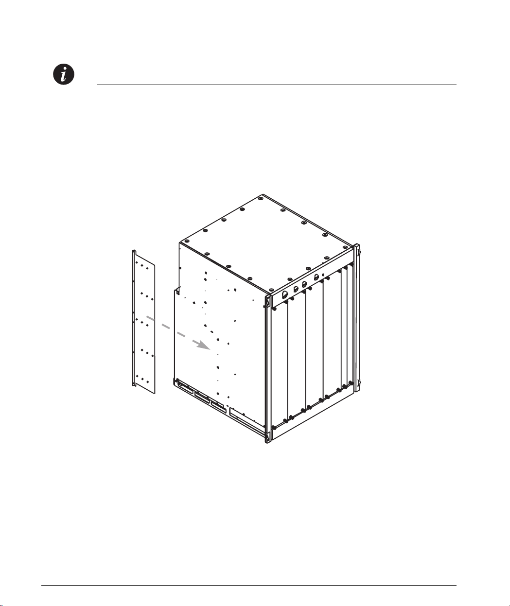
To install the plates perform the following steps:
1 When facing the hub, align each plate so that the narrow flange is toward the
rear of the hub, facing out. See Figure 1.1.
2 From inside the hub, screw on the 4 flat-headed screws to secure the plate to the
side of the hub.
Figure 1.1 Attaching the Depth Adjusting Plate
Decorative Edge Panels
The two plastic side-panels can be removed to allow access to the screw holes.
Simply unclip the panels and replace them. The panels are interchangeable.
2 Avaya M770 User’s Guide
Page 13
Chapter 2
Introduction
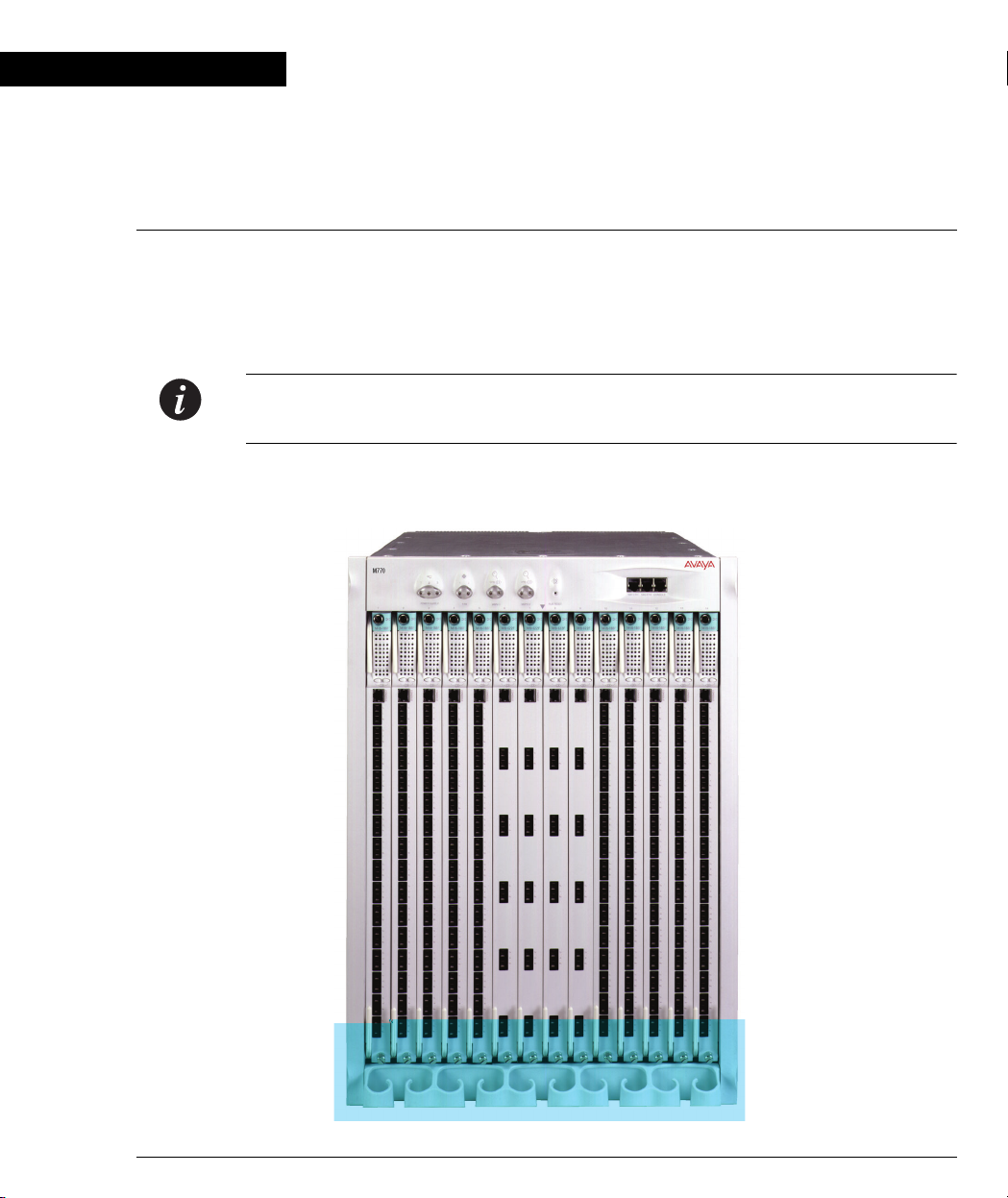
The Avaya M770 Multifunction Switch is a completely modular, integrated switch
which seamlessly integrates all switching protocols in a single hub.
The combination of Cell Switching and Frame Switching provides switching for
ATM, Ethernet, Fast Ethernet, and Gigabit Ethernet.
Note: The ATM functionality of the Avaya M770 is detailed in the M770 ATM
Switch User’s Guide.
Figure 2.1 The Avaya M770 Multifunction Switch
Avaya M770 User’s Guide 3
Page 14

Chapter 2 Introduction
ppp
ppp
ppp
ppp
ppp
XXX
ppp
ppp
XXX
ppp
Architecture
The Avaya M770 hub features distributed processing on each of the modules, so
there is no single point of failure. Most of the switching takes place on the module
itself; only when a packet must travel from one module to another does it traverse
the backplane. It is this combination of module and backplane switching that
enables the Avaya M770 to deliver aggregate bandwidth of over 80 Gbps.
The Avaya M770 Multiswitching Backplane
The Avaya M770 architecture enables you to use whichever mix of switching
technologies you require.
The Avaya M770 hub has multiple modular backplanes, allowing connection of
Frame switch, Cell switch, and Avaya M440 Gate Switch modules.
The lower section of the backplane is dedicated to frame switching and supports
two frame switches, called DomainXs. Frame Switch modules can be inserted into
either of the DomainXs - DomainXL in the left half of the hub (slots 1-7), DomainXR
in the right half of the hub (slots 8-14).
The upper backplane supports two switches called DomainGs, currently used for
cell switching. Cell switch modules can be inserted into either of the DomainGs DomainGL in the left half of the hub, DomainGR in the right half of the hub.
Although the upper backplane is currently utilized for ATM cell transfer, its bus
architecture is open, and can be easily adapted to support new technologies as they
emerge.
The lower section of the backplane also includes the High Speed bus for Avaya
M440 modules and their agent modules. Since these modules are 6U high, an
adapter bracket is required for their insertion (see Chapter 5).
Figure 2.2 Avaya M770 Backplane Architecture
MMMuuullltttiiipppllleee RRReeesssiiillliiieeennnttt SSSwwwiiitttccchhhiiinnnggg DDDooommmaaaiiinnnsss
777 SSSllloootttsss
UUU
eeerrr BBBaaaccckkk
CCCeeellllll SSSwwwiiitttccchhh
LLLooowwweeerrr BBBaaaccckkk
FFFrrraaammmeee SSSwwwiiitttccchhh
lllaaannneee
lllaaannneee
DDDooommmaaaiiinnn GGGLLL
DDDooommmaaaiiinnn
666 GGGbbb
sss
444000 GGGbbb
LLL
sss
222...555666 GGGbbbpppsss CCCeeelllllleeennniiiuuummm BBBuuusss
4 Avaya M770 User’s Guide
777 SSSllloootttsss
DDDooommmaaaiiinnn GGGRRR
444000 GGGbbb
DDDooommmaaaiiinnn
666 GGGbbb
sss
RRR
sss
Page 15

DomainX Budget Calculation
The maximum number of DomainX modules you can insert in the hub is
determined by domain usage considerations, as follows (M-SPV refers to either the
M-SPV or the M-SPX in the following examples):
The Avaya M770 allows a maximum of 100 Domain Resource Units (DRUs) for
DomainXL (Left DomainX - slots 1-7) and the M-SPV, and 100 DRUs for DomainXR
(Right DomainX - slots 8-14) and the M-SPV. Each of the DomainX modules, as well
as the M-SPV module, has a DRU budget, as shown in the table below. When
planning your hub configuration, calculate whether it fits the Avaya M770 DRU
budget.
Table 2.1 DRU Budget of DomainX Modules
Module Name DRU Budget
M-SPV/M-SPX 10 DRUs
M12-100T 18 DRUs
M12-100F 18 DRUs
M2-1000 15 DRUs
M-MLS 6 DRUs
Chapter 2 Introduction
M14-10F 6 DRUs
M24-10T 9 DRUs
Budget Calculation Examples
1 If you have six M14-10F modules, an M2-1000 module and the M-SPV you get:
6*6+15+10 = 61 DRUs. Assuming that you have the same configuration on the
DomainXL and Domain XR switches you get a total of 168 Ethernet, 12 Fast
Ethernet and 4 Gigabit ports.
2 If you have five M12-100 modules and the M-SPV you get: 5*18+10 = 100 DRUs.
Assuming that there are five modules on both the DomainXL and Domain XR
switches you get a total of 120 ports.
3 If you have six M2-1000 modules and the M-SPV you get: 6*15+10=100 DRUs.
Assuming that there are six modules on both the DomainXL and Domain XR
switches you get a total of 24 Gigabit Ethernet ports and 72 Fast Ethernet ports.
4 If you have four M12-100 modules, one M2-1000 and the M-SPV/M-SPX you
get: 4*18+15+10=97 DRUs. This is less than 100 DRUs and is therefore another
possible configuration.
Avaya M770 User’s Guide 5
Page 16

Chapter 2 Introduction
Note: A redundant M-SPV does not affect the DRU calculations. However you must
include the active M-SPV twice, once for DomainXL and once for DomainXR.
DRU Overload
Warning: Always verify that the DRU calculation never exceeds 100 DRUs.
A DRU overload can be identified by:
• Blinking OPR LED of each module (can also indicate a module fault).
• Via the Avaya M770 CajunView Manager NMS application. Check the DRU report
window (in the Configuration drop-down Menu).
• Using the “Set Show” command in the Zoom view of the Avaya M770 CajunView
Manager.
DRU Budget Information Window
You can check the DRU budget information for your Avaya M770 hub via the
CajunView Network Management System (NMS). The following window shows
an example of a hub with 1 M-SPV/M-SPX, two M12-100T and one M12-100F
module.
Figure 2 DRU Budget Information Window
6 Avaya M770 User’s Guide
Page 17

Avaya M770 Management Architecture
The back of the Avaya M770 hub has two slots which house the main and backup
Avaya M770 Supervisor modules, called M-SPV/M-SPX. The Supervisor module,
together with the CajunView network management system, provides a zoom view
of the Avaya M770 hub and all resident modules, regardless of technology. A
graphical display shows the position of each module in the hub and its status in
real-time. The Supervisor module also handles basic configuration functions such as
enabling and disabling settings. To perform more advanced configuration and
monitoring functions, the Avaya M770 Supervisor launches distributed
management sub-agents, located on the modules themselves. The distributed
management architecture allows no single point of failure for hub management; it is
implemented as follows:
• DomainX Avaya M770 modules are managed by an on-board CPU, which is
responsible for module management. The frame switch modules are managed
as SNMP sub-agents, with the main M-SPV serving as their SNMP agent.
• Avaya M770 ATM modules are managed as sub-agents by a single ATM
module which is designated as the SNMP agent for all other ATM modules in
the hub. Each Avaya M770 ATM module has an on-board agent CPU.
• Modules based on any future technology will also be managed independently,
by a member of that technology family (as with the ATM modules).
• All Avaya M440 modules are managed by NMA-RS or NMA-RE agents.
Chapter 2 Introduction
Note: For proper management of Avaya M440 modules in the Avaya M770 hub, the
NMA-RS/NMA-RE modules should be upgraded to S/W version 8.1.6.
Avaya M770 User’s Guide 7
Page 18

Chapter 2 Introduction
8 Avaya M770 User’s Guide
Page 19

Chapter 3
Avaya M770 Hub Components
This chapter describes the key components of the Avaya M770 hub, including the
control panel, M-SPV/M-SPX management modules, M-PS power supplies and
fans. Field replacement of components is described in Chapter 4.
The Control Panel
The control panel is located at the top of the front of the Avaya M770. It contains
eight LEDs, three reset switches and three ports.
Figure 3.1 Control Panel Components
M770
2
3
1
1
OPR
2
OPR
MSPV-1
MSPX-1
OPR LED
FAN 1
LED
FAN
FAN 2
LED
123 45
PS-1
LED
PS-2
LED
PS-3
LED
Table 3.1 Avaya M770 Control Panel LEDs
LED Name Represents State Function
PS
(1, 2, 3)
Fan
(1, 2)
Power supply status
(for PS1, PS2, PS3)
Fan status
(for Fan 1, Fan 2)
SB1-ETH SB2-ETH CONSOLE
MSPX-2
OPR LED
HUB RESETPOWER SUPPLY
MSPX-2
Reset button
MSPV-2
6 7 8 9 10 11 12 13 14
MSPX-1
Reset button
On Power supply is
functioning normally
Blinking Power supply is faulty
Off No power supply
On Fan is functioning normally
Blinking Fan is faulty
Off No fan
Avaya M770 User’s Guide 9
Page 20

Chapter 3 Avaya M770 Hub Components
* See M-SPX Additional Options Section below
* See M-SPX Additional Options Section below
10 Avaya M770 User’s Guide
Page 21

Chapter 3 Avaya M770 Hub Components
** Use an opened paper clip or other pointed object to press the Reset button.
Avaya M770 Hub - Rear Panel Components
The M-SPV/M-SPX Supervisor Module, power supplies and fans are located on the
rear of the Avaya M770. Figure 3.2 shows a schematic illustration of the component
locations:
Figure 3.2 Avaya M770 Rear Panel
Power Supplies
(up to 3)
Fans (2)
M-SPV/M-SPX
Supervisor
AC Inlet
Air Outlet
Avaya M770 User’s Guide 11
Modules (2)
Page 22

Chapter 3 Avaya M770 Hub Components
The M-SPV/M-SPX Supervisor Module
This 9U module is essential for the correct functioning of the Avaya M770. The
module is located in the rear of the Avaya M770 (see Figure 3.2). Although the hub
has full functionality with only one agent, it is recommended to install an additional
module as a backup. The agent has the following key functions:
• The M-SPX supports Inter-Domain Switching (IDS) for combining the two
Avaya M770 X-Domains (not available in the M-SPV). Connecting the domains
doubles the available port count in a single switch. The M-SPX module can
operate in two modes with IDS on or IDS off.
• SNMP management
• Frame Switch arbitration
• Monitoring of Avaya M770 sub-systems, including:
— Power supplies
— Fans and temperature
— Informing the user and hub’s front panel LEDs of sub-system status
• Clock generation.
For more detailed information about the M-SPV/M-SPX please refer to the M-SPV
and M-SPX Installation Guides.
Caution: Do not mix M-SPV and M-SPX modules in the same hub.
Communication with the M-SPV/M-SPX
The M-SPX enables the SNMP agent entity of the Meritage 1400 to be accessed by
the Network Management Station (NMS) through its two sideband management
interfaces. Sideband communication is carried out through one of the autonegotiation 10/100M Ethernet sideband ports on the front panel of the hub, to
which you can connect the NMS. An additional interface for setup purposes is the
RS-232 Console connector on the hub’s front panel, to which a terminal or modem
can be connected.
Communication with Internal Management
The M-SPX has two additional SNMP communication links, used for internal
management communication:
• An Ethernet Management Bus (EMB) to communicate with all DomainX (12U)
modules (agents and sub-agents) in the hub.
• An Ethernet bus which communicates with NMA-R* agents, to support Legacy
hub (6U) modules.
12 Avaya M770 User’s Guide
Page 23

M-SPV/M-SPX Front Panel
Table 3.4 M-SPV/M-SPX Front Panel LEDs
LED Name Represents State Function
OPR
MAIN
New M-SPX Functionality
Module
Operationa
l Status
Main/
Backup
Chapter 3 Avaya M770 Hub Components
Figure 3.3M-SPX Front Panel
On Module is
functioning
normally
BlinkingModule is
faulty
On Main/active
M-SPV/M-SPX
Off Backup/
dormant
M-SPV/M-SPX
IDS Switch (M-SPX only)
The M-SPX front-panel Inter-Domain Switch (IDS) enables you to
combine the two Avaya M770 X-Domains, effectively doubling the
available port count. Set the switch ON or OFF as required.
Caution: When installing two M-SPX modules, the IDS switch must be
set to the same position on both modules.
Sideband Port SB2-ETH
Two RJ-45 Sideband ports, SB1-ETH and SB2-ETH, on the Avaya M770
hub front panel are supported by the M-SPX (see Figure 3.1). The
M-SPV supports only the SB1-ETH port.
Resetting the M-SPV/M-SPX
Each M-SPV/M-SPX can be reset individually via a reset button on the Control
Panel (see page 10) or using the reset button on the M-SPV/M-SPX module itself.
Resetting the M-SPV/M-SPX does not reset the entire hub (for details on resetting
the hub, see page 10).
Avaya M770 User’s Guide 13
Page 24

Chapter 3 Avaya M770 Hub Components
M-SPV/M-SPX Front Panel Port
The RJ-45 Console port on the M-SPV/M-SPX is used for terminal setup.
The M-PS Power Supply Unit
At least one M-PS Power Supply unit is necessary for the operation of the
Avaya M770 but up to three M-PSs can be installed in the hub.
For more detailed information about the Power Supply please refer to the M-PS
Installation Guide.
M-PS Indicator
In addition to the PS status LEDs on the control panel of the Avaya M770 hub, each
M-PS has a LED indicator on its rear panel for viewing its status at a glance during
insertion and replacement of M-PSs.
Table 3.5 M-PS Status LED
LED Name Represents State Function
STATUS Power Status
Power Budget Considerations
The recommended Avaya M770 configuration is two M-PS units, plus a third unit
for redundancy. Such a configuration supports any number of DomainX and Avaya
M440 modules in the hub.
If there is only one M-PS unit available, the maximum number of modules in the
hub is based on the following guidelines
• 5 or less DomainX modules, or
• 4 or less DomainX modules with 2 or less Avaya M440 modules,
• 3 or less DomainX modules with 5 or less Avaya M440 modules.
Two M-PS power supplies support any combination of Avaya M440 and DomainX
modules. For redundancy it is recommended to install the third M-PS as well.
1The guidelines take into consideration a maximum power consumption of
60W@48V for each DomainX module and 20W@5V for each Avaya M440 module.
The sub-systems’ power consumption (M-SPV/M-SPX, redundant M-SPV/M-SPX,
fans, backplanes) was also already taken into consideration.
Green Module is functioning normally
Amber Module is faulty
1
:
14 Avaya M770 User’s Guide
Page 25

Chapter 4
Replacing Components
The power supply units, supervisor modules, fans and backplanes are field
replaceable. All those components except the backplanes are hot-swappable, so that
the hub can remain operational while you are replacing them. You will need to
disassemble the Avaya M770 completely to replace the backplanes.
Figure 4.1 Replacing an M-PS, M-SPV/M-SPX or a Fan
Avaya M770 User’s Guide 15
Page 26

Chapter 4 Replacing Components
Replacing an M-PS
Any one of the power supplies can be hot-swapped without powering down the
hub. If not all three M-PS slots are occupied, insert the new M-PS into an empty slot
before removing the M-PS you wish to replace.
For more detailed information about the M-PS please refer to the M-PS Installation
Guide.
Inserting an M-PS
To insert a new M-PS, perform the following steps at the back of the Avaya M770
hub (see Figure 4.1):
1 If you are inserting an M-PS unit into an empty slot, remove the blank panel
covering the slot by unscrewing its four retaining screws.
If you are inserting an M-PS unit into an occupied slot, remove the M-PS unit
you wish to replace by following the directions in section Removing an M-PS
below.
2 Slide in the new M-PS, ensuring that it is positioned properly.
3 Tighten the four retaining screws.
4Fold the handle.
5 Plug the AC power connector plug into the AC inlet on the M-PS.
6 Plug the AC power supply plug into the wall socket.
7 Turn the M-PS on using its ON switch.
8 Verify that the STATUS LED adjacent to the M-PS ON/OFF switch is green.
Removing an M-PS
To remove an M-PS, perform the following steps at the back of the Avaya M770
hub:
1 Using the M-PS ON/OFF switch, turn off the M-PS which you wish to replace.
2 Unplug the AC power supply plug from its wall socket.
3 Unplug the AC power connector plug from the AC inlet on the M-PS.
4 Unscrew the four retaining screws.
5 Pull the handle to remove the M-PS.
6 Slide out the unit.
16 Avaya M770 User’s Guide
Page 27

Chapter 4 Replacing Components
Replacing a Supervisor Module (M-SPV/M-SPX)
Caution: The M-SPV/M-SPX is essential to the correct functioning of the Avaya
M770. It is therefore recommended to have two modules installed at all times.
However, you cannot install both an M-SPV and an M-SPX module in the same hub.
Either of the two M-SPV/M-SPX modules can be replaced without powering down
the Avaya M770 hub. If one slot is empty, insert the new module into the empty slot
and wait one minute before removing the module you wish to replace. The new MSPV/M-SPX automatically inherits the configuration of the main M-SPV/M-SPX
within one minute.
For more detailed information about the M-SPV/M-SPX please refer to the M-SPV
and M-SPX Installation Guides.
Inserting the M-SPV/M-SPX in the Hub
At the back of the Avaya M770 hub there are two slots for two M-SPX modules.
The M-SPX can be installed or removed while power is applied to the enclosure.
1 Insert the M-SPX into an available slot in the back of the hub. Plug in the
module by pressing firmly on the mid-section of the front panel.
2 Secure the module by folding the modules handles, and fastening the two
retaining screws. Do not over-tighten the screws.
3 If you intend to install two M-SPX modules into the hub, first insert one of them
and configure it completely as detailed in Chapter 3 of the M-SPX Installation
Guide. Next insert the second M-SPX, and it will auto-configure itself
identically to the first M-SPX (within 5 minutes).
Connecting the Console Terminal
Initial software configuration of the M-SPX is done using a console terminal
connected to the Console connector on the front of the Avaya M770 hub. Refer to the
Appendix for connector pin assignments.
To connect the Avaya M770 to a console terminal:
1 Turn on the VT100 terminal (or PC terminal emulator in VT100 or VT52 mode)
and set its communication parameters to:
Baud rate: 9600 bps
Start bit: 1
Data bits: 8
Stop bit: 1
Parity: None
Avaya M770 User’s Guide 17
Page 28

Chapter 4 Replacing Components
Refer to your terminal’s user manual for instructions on how to set these parame-
ters.
1 Insert the RJ-45 connector of the cable into the Console port at the top of the
Avaya M770 front panel.
2 Insert the other end of the cable into the terminal’s RS-232 port.
3 Press <Enter> to verify that the cabling process was successful. The main menu
appears.
Removing an M-SPV/M-SPX
To remove an M-SPV/M-SPX perform the following steps:
1 Release the two retaining screws, one at the top and one at the bottom of the
module.
2 Unfold the levers and gently slide the module out.
Replacing a Fan
Caution: The fan may rotate for a short while after it is removed from the Avaya
M770.
Note: Although one fan is sufficient to cool the Avaya M770, it is recommended to
use two fans to ensure maximum resiliance.
The fans are hot-swappable and interchangeable. One fan will fit on either the left or
right side: turn the fan upside down if necessary.
To replace a fan perform the following steps (see Figure 4.1):
1 Release the fan’s four screws and gently pull the unit out half way.
2 Wait until the fan stops rotating, then pull it out all the way.
3 Insert the replacement fan, ensuring that it is correctly aligned, and fasten the
four screws.
18 Avaya M770 User’s Guide
Page 29

Replacing a Backplane
The Avaya M770 has two backplanes. The lower backplane serves the X-switch and
Avaya M440 Gate Switch modules, while the upper backplane connects the
Avaya M770 ATM modules. Each backplane is sent with a detailed Installation
Guide. The location of each backplane in the hub is shown in Figure 4.2 below.
Figure 4.2 Avaya M770 Backplanes
Chapter 4 Replacing Components
Avaya M770 User’s Guide 19
Page 30

Chapter 4 Replacing Components
20 Avaya M770 User’s Guide
Page 31

Chapter 5
Using Avaya M440 Gate Switch 6U Modules
Permissible 6U Modules and their Location
The Avaya M770 supports all switching modules (LSA+, LSE-108, LSE-208, LSE-404,
LSE-404S, LSE-808, LSF-100, LFE-100, LFE-1008, LFE-4004, LFE-4004S, LBT-155,
LHB, LEB-200 and 3LS) but not shared Ethernet modules. All Avaya M440 modules
can be inserted into the hub, using a module adapter (see following section). There
are several considerations to keep in mind when using Avaya M440 modules:
1 The NMA-RS agent module should be inserted into slot 13 and 14 of the hub.
2 The NMA-RE agent module should be inserted into slot 14 of the hub.
3 You can use the LSE-MON module only if you set its internal jumper to Clock
Disable (applicable only to C/S version D and up).
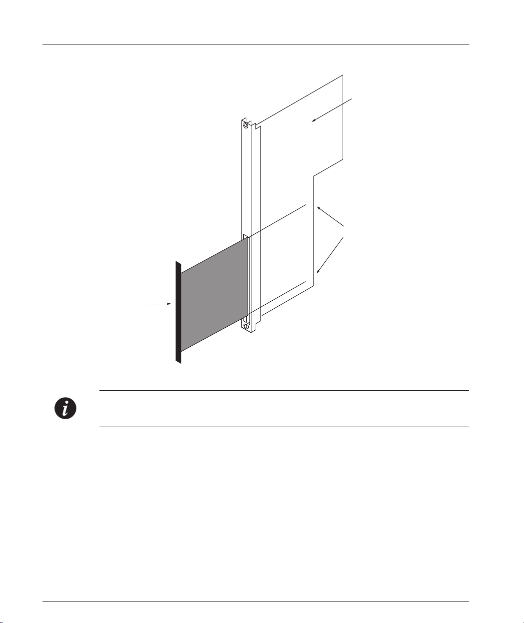
Using the 6U Module Adapter
This section explains how to insert 6U Avaya M440 modules in the Avaya M770 hub
using the optional adapters.
Two types of adapters are available:
1 M-LS1 single-slot 6U module
2 M-LS2 dual-slot 6U module.
Use the type appropriate for the 6U module you are inserting.
Caution: The 6U modules contain components which are sensitive to electrostatic
discharge (ESD). To prevent ESD damage handle the module by its edges and do
not touch the circuit board components unless instructed to do so.
Before handling the module, touch the Avaya M770 chassis to discharge any
electrostatic charge on your body.
In order to use the adapter perform the following steps:
1 Insert the adapter into the Avaya M770 until the adapter is correctly sited, and
tighten the adapter screws.
2 Insert the 6U module gently into the adapter as shown in Figure 5.1.
3 Gently tighten the module’s retaining screws.
To remove an adapter:
1 Release the module’s retaining screws, and pull the module out by its handle.
2 Release the adapter’s screws, and pull the adapter out.
Avaya M770 User’s Guide 21
Page 32
Chapter 5 Using Avaya M440 Gate Switch 6U Modules
Figure 5.1 Inserting the 6U Module
Avaya M440
Gate Switch
6U Module
Adapter
Guide Rails
Note: It is also possible to insert and remove modules in an adapter which is already
in the hub.
22 Avaya M770 User’s Guide
Page 33

Index
Numerics
6U modules 21
Adapter 21
Inserting 21
Location 21
Permissible modules 21
Using 21
A
Agent reset 10
Architecture 4
B
Backplane 4
Overview 19
Budget calculation examples 5
C
Cable manager 1
Calculating DomainX budget 5
Certification I
Communication
With the M-SPV 12
Components
Rear panel 11
Replacing 15
Console port 14
Control Panel
Components 9
LEDs 9
Overview 9
Ports 10
D
Decorative edge panels 2
Depth-adjusting plates 1
DomainX budget calculation 5
E
Edge panels 2
Energy I
F
Fan replacement 18
H
High Voltage I
How to
Calculate DomainX budget 5
Install decorative edge panels 2
Install depth-adjusting plates 1
Install the cable manager 1
Replace a backplane 19
Replace a fan 18
Replace a supervisor module 17
Replace an M-PS 16
Reset the M-SPV 13
Use 6U module adapter 21
Use LANswitch 6U modules 21
Hub
Components 9
Resetting 10
I
Important Information I
Inserting 6U modules 21
Installing
Cable manager 1
Depth-adjusting plates 1
Introduction to Meritage 1400 3
L
LANswitch 6U modules 21
Location of 6U modules 21
M
Management architecture 7
Management module replacement 17
Management modules 15
Modules
6U 21
M-PS
Indicator 14
Avaya M770 User’s Guide 23
Page 34

Index
Power supply unit 14
Replacing 16
M-SPV
Front panel 13
Overview 15
Replacing 17
Supervisor module 12
Multiswitching backplane 4
N
National Power Plug I
P
Permissible 6U modules 21
Ports control panel 10
Power budget considerations 14
Power supply unit
Overview 14
Replacing 16
Q
Quick Start 1
R
Rear panel components 11
Replacing
Backplane 19
Components 15
Fan 18
M-SPV 17
PSU 16
Supervisor module 17
Replacing an M-SPV 17
Resetting
Agent 10
Hub 10
M-SPV 13
S
Safety Considerations I
U
Using
6U module adapter 21
LANswitch 6U modules 21
V
Ventilation I
W
Wiring I
24 Avaya M770 User’s Guide
Page 35

How to Contact Us
To contact Avaya’s technical support, please call:
In the United States
Dial 1-800-237-0016, press 0, then press 73300.
In the EMEA (Europe, Middle East and Africa) Region
Country
Albania +31 70 414 8001 France +33 1 4993 9009
Austria +43 1 36 0277 1000 Germany +49 69 95307 680
Azerbaijan +31 70 414 8047 Ghana +31 70 414 8044
Bahrain +800 610 Gibraltar +31 70 414 8013
Belgium +32 2 626 8420 Greece +00800 3122 1288
Belorussia +31 70 414 8047 Hungary +06800 13839
Bosnia
Herzegovina
Bulgaria +31 70 414 8004 Ireland +353 160 58 479
Croatia +31 70 414 8039 Israel +1 800 93 00 900
Cyprus +31 70 414 8005 Italy +39 02 7541 9636
Czech Rep. +31 70 414 8006 Jordan +31 70 414 8045
Denmark +45 8233 2807 Kazakhstan +31 70 414 8020
Egypt +31 70 414 8008 Kenya +31 70 414 8049
Local Dial-In
Number
+31 70 414 8042 Iceland +0800 8125
Country
Local Dial-In
Number
Estonia +372 6604736 Kuwait +31 70 414 8052
Finland +358 981 710 081 Latvia +371 721 4368
Avaya M770 User’s Guide 25
Page 36

How to Contact Us
Country
Local Dial-In
Number
Country
Local Dial-In
Number
Lebanon +31 70 414 8053 Slovakia +31 70 414 8066
Lithuania +370 2 756 800 Slovania +31 70 414 8040
Luxemburg +352 29 6969 5624 South Africa +0800 995 059
Macedonia +31 70 414 8041 Spain +34 91 375 3023
Malta +31 70 414 8022 Sweden +46 851 992 080
Mauritius +31 70 414 8054 Switzerland +41 22 827 8741
Morocco +31 70 414 8055 Tanzania +31 70 414 8060
Netherlands +31 70 414 8023 Tunisia +31 70 414 8069
Nigeria +31 70 414 8056 Turkey +800 4491 3919
Norway +47 235 001 00 UAE +31 70 414 8036
Oman +31 70 414 8057 Uganda +31 70 414 8061
Pakistan +31 70 414 8058 UK +44 0207 5195000
Poland +0800 311 1273 Ukraine +31 70 414 8035
Portugal +351 21 318 0047 Uzbekistan +31 70 414 8046
Qatar +31 70 414 8059 Yemen +31 70 414 8062
Romania +31 70 414 8027 Yugoslavia +31 70 414 8038
Russia +7 095 733 9055 Zimbabwe +31 70 414 8063
Saudi Arabia +31 70 414 8022
Email: csctechnical@avaya.com
26 Avaya M770 User’s Guide
Page 37

In the AP (Asia Pacific) Region
How to Contact Us
Country
Local Dial-In
Number
Australia +1800 255 233 Malaysia +1800 880 227
Hong Kong +2506 5451 New
Indonesia +800 1 255 227 Philippines +1800 1888 7798
Japan +0 120 766 227 Singapore +1800 872 8717
Korea +0 80 766 2580 Taiwan +0 80 025 227
Email: sgcoe@avaya.com
In the CALA (Caribbean and Latin America) Region
Email: caladatasupp@avaya.com
Hot Line:+1 720 4449 998
Fax:+1 720 444 9103
For updated information, visit www.avayanetwork.com, and click “Global Support
Organization (GSO)”.
Country
Zealand
Local Dial-In
Number
+00 800 9828 9828
Avaya M770 User’s Guide 27
Page 38

How to Contact Us
All trademarks, registered trademarks, service names, product and/or brand names are the sole property of
their respective owners.
Copyright © 2001 Avaya Inc. All rights reserved.
28 Avaya M770 User’s Guide
 Loading...