

Page 1

IP Office 2.1
Installation Manual
40DHB0002USCL Issue 10c (11th May 2004)
Page 2

Page 3

Installation Manual Page i
IP Office 2.1 40DHB0002USCL Issue 10c (11th May 2004)
Table Of Contents
IP Office Installation................................................................................................................... 1
Scope of Manual ........................................................................................................................2
Scope of Manual ........................................................................................................................3
IP401 Compact Office Platform................................................................................................. 5
IP401 Compact Office ................................................................................................................................ 5
IP401 Compact Office - Front View ............................................................................................................ 6
IP401 Compact Office - Rear View............................................................................................................. 7
Typical Configuration.................................................................................................................................. 8
IP403 Office Platform................................................................................................................. 9
IP403 Office................................................................................................................................................ 9
IP403 Office - Front View ......................................................................................................................... 11
IP403 Office - Rear View .......................................................................................................................... 12
Typical Configuration................................................................................................................................ 13
IP406 Office Platform............................................................................................................... 15
IP406 Office.............................................................................................................................................. 15
IP406 Office - Front View ......................................................................................................................... 16
IP406 Office - Rear View .......................................................................................................................... 17
Typical Configurations .............................................................................................................................. 18
IP412 Office Platform............................................................................................................... 21
IP412 Office.............................................................................................................................................. 21
IP412 Office - Front View ......................................................................................................................... 22
IP412 Office - Rear View .......................................................................................................................... 23
Scenario 1 ................................................................................................................................................ 24
Scenario 2 ................................................................................................................................................ 25
Expansion Modules ................................................................................................................. 27
IP400 Digital Terminal 16/30 .................................................................................................................... 27
IP400 Digital Stations 16/30 ..................................................................................................................... 28
IP400 Phone 8/16/30................................................................................................................................ 28
IP400 So8................................................................................................................................................. 29
IP400 WAN3............................................................................................................................................. 30
IP400 Analog Trunk 16............................................................................................................................. 31
Country Variants ...................................................................................................................... 33
Overview of Country Variants................................................................................................................... 33
IP400 Office Systems ............................................................................................................................... 34
Integral Module Kits.................................................................................................................................. 35
Trunk Module Kits..................................................................................................................................... 36
Power Supplies......................................................................................................................................... 37
IP Office Rack Mounting Kits.................................................................................................................... 37
Expansion Modules .................................................................................................................................. 38
Preparing for Installation......................................................................................................... 39
Preparing for Installation........................................................................................................................... 39
Tools & Parts Required ............................................................................................................................ 39
Space requirements ................................................................................................................................. 40
Environmental requirements..................................................................................................................... 41
Power Supply requirements ..................................................................................................................... 42
Grounding................................................................................................................................................. 43
Grounding ............................................................................................................................................ 43
Protective Ground ................................................................................................................................ 43
Functional Ground ............................................................................................................................... 44
Out of Building Telephone Installations .................................................................................................... 45
Page 4

Table Of Contents
Installation Manual Page ii
IP Office 2.1 40DHB0002USCL Issue 10c (11th May 2004)
Out of Building Telephone Installations ............................................................................................... 45
Rack Mounting Barrier Boxes .............................................................................................................. 46
Installing a New System .......................................................................................................... 49
Unpacking................................................................................................................................................. 49
Trunk Interface Modules (BRI/PRI/ANALOG4) ........................................................................................ 50
Installation of Voice Compression Modules (VCM) .................................................................................. 51
Dual Modem Module ................................................................................................................................ 52
Rack Mounting Assembly Instructions...................................................................................................... 53
IP401 Expansion and Installation of Integral Modules.............................................................................. 54
IP401 Compact Office Wall Mounting....................................................................................................... 55
Initial Assembly......................................................................................................................................... 56
Basic System Programming ................................................................................................... 57
Introduction............................................................................................................................................... 57
Programming Tools .................................................................................................................................. 58
Programming Tools.............................................................................................................................. 58
PC to IP Office LAN Port Connection .................................................................................................. 58
Initial Programming................................................................................................................................... 59
Initial Programming .............................................................................................................................. 59
Using the IP Office Installation Wizard:................................................................................................ 60
Using the IP Office Manager Application: ............................................................................................ 60
Software Upgrades................................................................................................................................... 61
Software Upgrades .............................................................................................................................. 61
Upgrading an IP403 to Software Level 2.1 .......................................................................................... 63
Telephone Installation ............................................................................................................. 65
Checking Telephones............................................................................................................................... 65
Checking Telephones .......................................................................................................................... 65
Connecting & Testing IP Office Telephones ........................................................................................ 65
Connecting & Checking Two-Wire Telephones ................................................................................... 66
Power Fail Telephones and Sockets ................................................................................................... 66
Wall Mounting 2000 Series Telephones................................................................................................... 67
Wall Mounting 44/4600, 2420 & 6400 Series Telephones ....................................................................... 68
System Handover..................................................................................................................... 69
Checklist ................................................................................................................................................... 69
Safety and Homologation Statements.................................................................................... 71
Safety and Homologation Statements ...................................................................................................... 71
Lithium Batteries....................................................................................................................................... 71
Lightning Protection/Hazard Symbols ...................................................................................................... 71
Electromagnetic Interference Information................................................................................................. 72
Federal Communications Commission (FCC) ..................................................................................... 72
Canadian Department of Communications (DOC)............................................................................... 72
Trunk Interface Modules........................................................................................................................... 73
USA/Canada ........................................................................................................................................ 73
Rest Of World (ROW) .......................................................................................................................... 73
Further Information and Product Updates ................................................................................................ 74
Further Information and Product Updates............................................................................................ 74
Support Telephone Numbers............................................................................................................... 74
Regulatory Instructions for Use ................................................................................................................ 75
Regulatory Instructions for Use............................................................................................................ 75
IP Office Operation in Australia............................................................................................................ 75
Industry Canada Notification (DoC) ..................................................................................................... 76
IP Office Operation in EU..................................................................................................................... 76
IP Office Operation in New Zealand .................................................................................................... 76
IP Office Operation in USA .................................................................................................................. 77
Technical Data.......................................................................................................................... 79
Port Pinouts .............................................................................................................................................. 79
Page 5

Table Of Contents
Installation Manual Page iii
IP Office 2.1 40DHB0002USCL Issue 10c (11th May 2004)
Port Pinouts ......................................................................................................................................... 79
Analog Trunk Ports (RJ45) .................................................................................................................. 79
Power Fail and POT Ports (RJ45) ....................................................................................................... 79
DS/DT Ports (RJ45) ............................................................................................................................. 79
ISDN Port – BRI (RJ45) ....................................................................................................................... 80
ISDN Port – PRI (RJ45) ....................................................................................................................... 80
LAN Port – 10/100 BaseT .................................................................................................................... 80
DTE Port (25 Way or 9 Way D-Type socket) ....................................................................................... 81
Audio Port (3.5mm Stereo Jack Socket).............................................................................................. 81
Expansion Port (RJ45 Socket)............................................................................................................. 81
External Control Port (3.5mm Stereo Jack Socket) ............................................................................. 82
WAN Port (37 Way D-Type Socket)..................................................................................................... 83
Cables ...................................................................................................................................................... 84
Cables.................................................................................................................................................. 84
DTE Cable ........................................................................................................................................... 84
DT Line Cord for Structured Cabling.................................................................................................... 85
PRI/BRI ISDN Cable ............................................................................................................................ 86
LAN Interconnect Cable....................................................................................................................... 87
LAN Cable............................................................................................................................................ 88
LAN Crossover Cable .......................................................................................................................... 89
Expansion Interconnect Cable ............................................................................................................. 90
V.24/V.28 WAN Cable ......................................................................................................................... 91
X.21 WAN Cable.................................................................................................................................. 92
V.35 WAN Cable.................................................................................................................................. 93
Telephone Converter Cables ............................................................................................................... 94
Port Safety Classification.......................................................................................................................... 95
Port Safety Classification ..................................................................................................................... 95
Compliance with FCC Rules ................................................................................................................ 96
Technical Specifications ........................................................................................................................... 97
General ................................................................................................................................................ 97
Interfaces ............................................................................................................................................. 98
Protocols .............................................................................................................................................. 99
Internal Data Channels ...................................................................................................................... 100
SNMP....................................................................................................................................... 101
SNMP Functionality ................................................................................................................................ 101
SNMP Agent Configuration .................................................................................................................... 101
MIBs Supported...................................................................................................................................... 102
Trap Generation ..................................................................................................................................... 103
MIB Loading ........................................................................................................................................... 104
HP OpenView Network Node Manager 6.41 and earlier: ....................................................................... 104
CastleRock SNMPc 5.1.6c and earlier: .................................................................................................. 105
Index........................................................................................................................................ 107
Page 6

Page 7

Installation Manual Page 1
IP Office 2.1 40DHB0002USCL Issue 10c (11th May 2004)
IP Office Installation
This manual covers the installation of your Avaya IP401/403/406/412 Office equipped with software
release Level 1.0+ through to 2.1. It is intended for use by installers and maintainers who have
successfully completed the appropriate IP Office training courses.
• Ensure that you have read and understood this manual before beginning installation.
For installation instructions for the Avaya IP Office - Small Office Edition, refer to the separate Small
Office Edition Installation Manual.
Page 8

IP Office Installation
Installation Manual Page 2
IP Office 2.1 40DHB0002USCL Issue 10c (11th May 2004)
Scope of Manual
This manual, for Avaya IP Office systems, covers the following subjects and should be read in the
sequence shown below:
• Avaya IP Office Platforms
This section provides details of the various Avaya IP Office platforms available. Illustrations of the
front and rear of each unit show what ports/sockets/etc are provided. Typical configuration
examples are also provided in this section. A further section details the country variants of
modules/trunks/integral modules/etc.
• Preparing for and Installing a new system
These sections provide all the information required and the actions to be performed to physically
install an IP Office, i.e. what tools are required, the environmental/power requirements, wall
mounting, rack mounting, etc. The software installation is covered in the following section.
• Basic System Programming
System programming is necessary for configuration and maintenance of the Avaya IP Office.
This manual only covers the installation of the IP Office suite of programs. For full details refer to
the Installation Wizard Help files and/or to the Manuals contained on the documentation CD
(supplied with every unit).
• Terminal/Telephone Installation
This manual details the information required to install telephone but does not detail the usage
and functionality of IP Office terminals/telephones. These details are to be found in the
appropriate User Guides. The terminals/telephones that are supported by the IP Office are (these
are also used across a number of Avaya platforms:
• Avaya 2000 Series: 20AT, 20CC, 2010, 2030, 2050, 20DSS/BLF and 20DT.
• Avaya 2400 Series: 2420.
• Avaya 3600 Series: 3616, 3626.
• Avaya 4400 Series: 4406D, 4412D, 4424D and 4450DSS*.
• Avaya 4600 Series: 4602, 4602SW, 4620, 4606, 4612 and 4624.
• Avaya 6400 Series: 6408D+, 6416D+M, 6424D+M and XM24 (DSS).
• *Caution: See DT Line Cord for Structured Cabling for wiring details on a
4450DSS module.
• Safety and Homologation Statements
This provides all the necessary Safety, Homologation Statements and Regulatory Instructions for
Use required. This section also detail where further information, including other Manuals and
support telephone numbers, can be obtained
• Technical Data
This manual contains information on the Port Pinouts/Safety classifications, cables, and basic
technical specifications only (see Technical Specifications). Descriptions of the functionality,
features and performance of the IP Office are covered by the Product Description.
Page 9

Installation Manual Page 3
IP Office 2.1 40DHB0002USCL Issue 10c (11th May 2004)
Scope of Manual
This manual, for Avaya IP Office systems, covers the following subjects and should be read in the
sequence shown below:
• Avaya IP Office Platforms
This section provides details of the various Avaya IP Office platforms available. Illustrations of the
front and rear of each unit show what ports/sockets/etc are provided. Typical configuration
examples are also provided in this section. A further section details the country variants of
modules/trunks/integral modules/etc.
• Preparing for and Installing a new system
These sections provide all the information required and the actions to be performed to physically
install an IP Office, i.e. what tools are required, the environmental/power requirements, wall
mounting, rack mounting, etc. The software installation is covered in the following section.
• Basic System Programming
System programming is necessary for configuration and maintenance of the Avaya IP Office.
This manual only covers the installation of the IP Office suite of programs. For full details refer to
the Installation Wizard Help files and/or to the Manuals contained on the documentation CD
(supplied with every unit).
• Terminal/Telephone Installation
This manual details the information required to install telephone but does not detail the usage
and functionality of IP Office terminals/telephones. These details are to be found in the
appropriate User Guides. The terminals/telephones that are supported by the IP Office are (these
are also used across a number of Avaya platforms:
• Avaya 2000 Series: 20AT, 20CC, 2010, 2030, 2050, 20DSS/BLF and 20DT.
• Avaya 2400 Series: 2420.
• Avaya 3600 Series: 3616, 3626.
• Avaya 4400 Series: 4406D, 4412D, 4424D and 4450DSS*.
• Avaya 4600 Series: 4602, 4602SW, 4620, 4606, 4612 and 4624.
• Avaya 6400 Series: 6408D+, 6416D+M, 6424D+M and XM24 (DSS).
• *Caution: See DT Line Cord for Structured Cabling for wiring details on a
4450DSS module.
• Safety and Homologation Statements
This provides all the necessary Safety, Homologation Statements and Regulatory Instructions for
Use required. This section also detail where further information, including other Manuals and
support telephone numbers, can be obtained
• Technical Data
This manual contains information on the Port Pinouts/Safety classifications, cables, and basic
technical specifications only (see Technical Specifications). Descriptions of the functionality,
features and performance of the IP Office are covered by the Product Description.
Page 10

Page 11

Installation Manual Page 5
IP Office 2.1 40DHB0002USCL Issue 10c (11th May 2004)
IP401 Compact Office Platform
IP401 Compact Office
The IP401 Compact Office system platform is supplied in two variants:
• IP401 Compact Office 2 supports: Two digital and two analog telephones A BRI ISDN port (2
trunks) An four port auto-negotiating 10/100 BaseT LAN hub.
• IP401 Compact Office 4 supports: Four digital and four analog telephones Two BRI ISDN
ports (4 trunks) An eight port auto-negotiating 10/100 BaseT LAN hub. The IP401 Compact
Office 2 can be expanded to an IP401 Compact Office 4.
See IP400 Office Systems
for country specific variants.
The auto-negotiating 10/100 BaseT LAN hub provides access to networks and/or up to eight IP
telephones.
The DT ports support Avaya 2000 series telephones. DT ports are set to A-Law PCM encoding at default
but can be programmed to -Law PCM encoding.
In addition the IP401 Compact Office can be fitted with any of the following optional Integral Modules:
• WAN Port
This port supports a single synchronous data connection, which can be X.21, V.35 or V.24.
• Voice Compression Module (VCM5)
Supports VoIP applications (over two of the five channels) using Avaya 4600 IP telephones
connected via LAN ports.
• VME card
Provides memory capacity for embedded voice mail feature.
Page 12
IP Office Installation
Installation Manual Page 6
IP Office 2.1 40DHB0002USCL Issue 10c (11th May 2004)
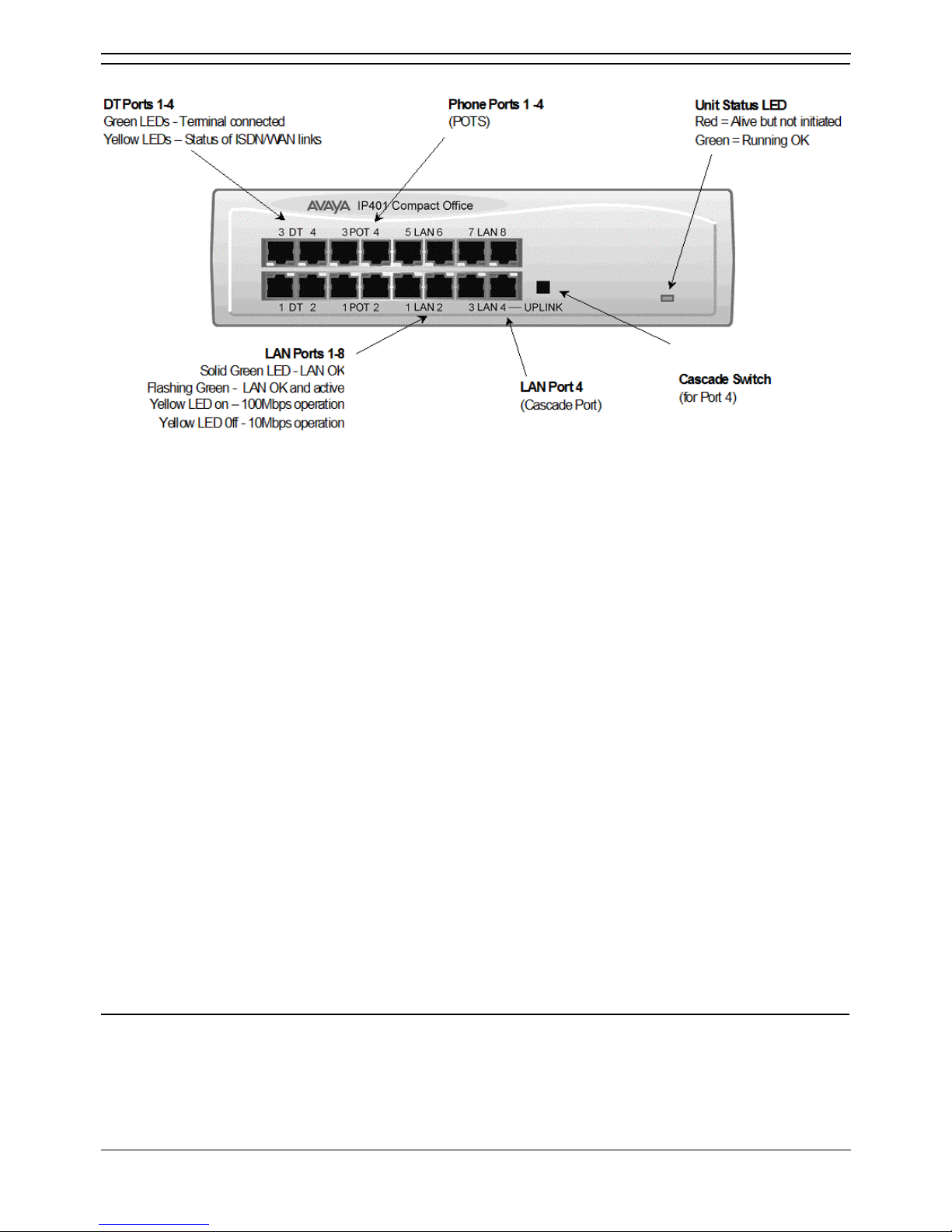
IP401 Compact Office - Front View
• Note
The IP Compact Office DT4 is shown above. The IP Compact Office DT2 does not have
the top row (labeled 3 DT 4, 3 POT 4, 5 LAN 6 and 7 LAN 8) of RJ45 ports fitted.
• DT Ports
DT ports are used for connection to Avaya 2000 series telephones and support either A-Law or Law PCM encoding (default A-Law). Using DT Line Cords and standard structured wiring, these
RJ45 ports can be extended to the required telephone location. In addition, converters can be
used to provide BT New Plan sockets (431A/631A) if required. When telephones are equipped
with line cords that terminate in RJ11 plugs, then pin-to-pin RJ11/RJ45 adapters should be used.
• Plain Ordinary Telephone (POT) Ports
These ports are used for connection to standard analog telephones, fax machines and modems.
These ports must not be used for connection to trunks. Using standard structured wiring, these
RJ45 ports can be extended to the required telephone location. Converters can be used to
provide BT New Plan sockets (431A/631A) if required. When telephones are equipped with line
cords that terminate in RJ11 plugs, then pin-to-pin RJ11/RJ45 adapters should be used.
• LAN Ports
The auto-negotiating 10/100 BaseT LAN hub ports are used for PC and server connectivity. They
can also be used to connect to IP telephones (Avaya 4600 IP series).
• LAN ports allow information relating to incoming and outgoing telephone calls to be
forwarded to PC based applications. They also provide access to the router
functionality/configuration of the IP401 Compact Office platform for both data and Voice
over IP (VoIP) calls. The auto-negotiating 10/100 BaseT LAN hub ports support a single
MAC address only (printed on base of unit).
• Where more than eight LAN connections are required, the fourth LAN port can be used
for cascading to other hubs. The Uplink push button to the right of this port is used to set
the mode. When the Uplink switch is in the out position the port can be connected to
another hub without the need for a crossover cable, i.e. the port is an MDI type port.
When the Uplink switch is in the in position the port can be connected directly to a PC.
Cables
IP401 Compact Office 2 is supplied with one red CAT5E cable. The Compact Office 4 is supplied with
two red CAT5E cables.
Page 13
IP401 Compact Office Platform
Installation Manual Page 7
IP Office 2.1 40DHB0002USCL Issue 10c (11th May 2004)
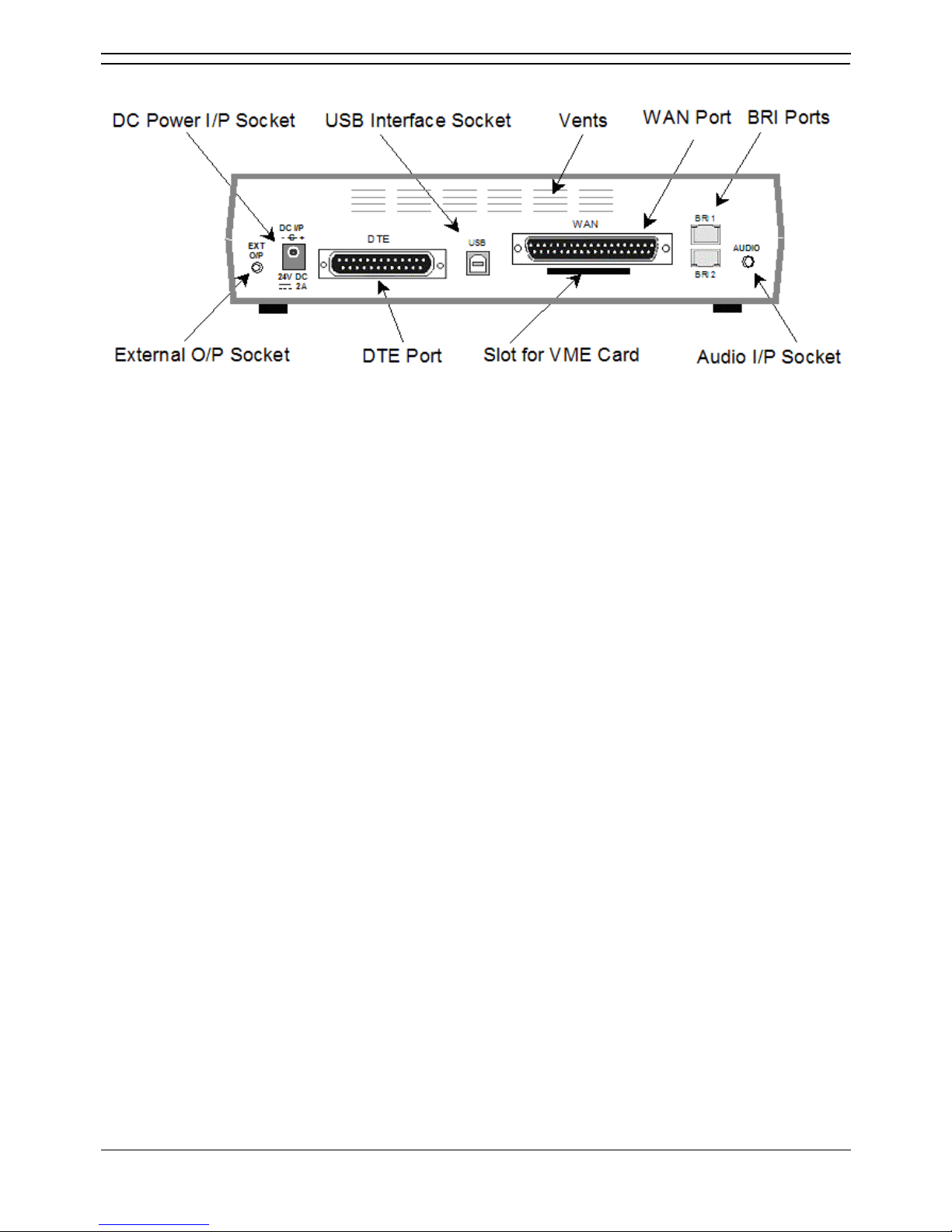
IP401 Compact Office - Rear View
• Notes:
1. The IP401 Compact Office 4 is shown above; the WAN port is optional.
2. On an IP401 Compact Office 2, the WAN port is optional and BRI 1 is not fitted.
3. The IP401 Compact Office can be wall mounted.
• External O/P Socket
Allows externally powered circuits to be controlled via a single 3.5mm stereo jack socket.
• DC Power I/P Socket
Socket for the external 24V DC unregulated power supply (supplied with kit).
• DTE Port
A 25-way D-type socket. Used for connection to PCs, servers and EFTPOS terminals.
• BRI Ports
Two BRI trunk interface ports are fitted on an IP401 Compact Office 4 and only one on an IP401
Compact Office 2; providing four and two trunks respectively. See IP401 Expansion and
Installation of Integral Modules for expansion and IP400 Office Systems for country specific
variants.
• WAN Port
This port supports a single synchronous data connection, which can be X.21, V.35 or V.24. The
selection of the required interface is automatically determined from the pin-out of the cable
plugged into the 'WAN' port. This cable must be connected before power is applied for auto
detection to work. Connection to a Digital Leased Circuit is made by connecting the WAN port on
the rear of the unit to the existing Network Terminating Unit (NTU) via the appropriate X.21, V.35
or V.24 cable.
• USB Interface
Not used.
• Audio I/P Socket
A single 3.5mm stereo or mono jack socket that enables input from an external 'Music-on-Hold'
source.
Page 14
IP Office Installation
Installation Manual Page 8
IP Office 2.1 40DHB0002USCL Issue 10c (11th May 2004)
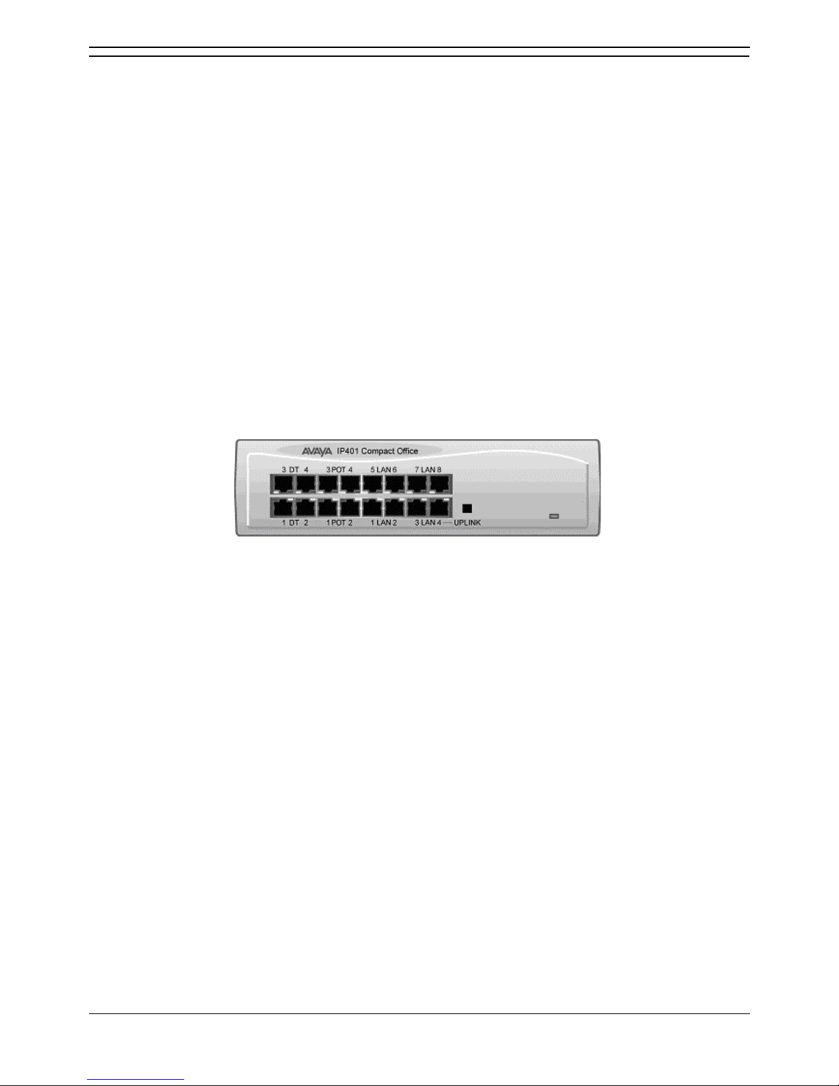
Typical Configuration
Scenario
A customer requiring a voice and data solution for a warehousing facility remote from a regional office.
Three administrators and two pickers staff the warehouse.
This configuration provides support for four Avaya 2000 series digital telephones, one for each of the
administrators, leaving a spare port for future growth. Up to four analog telephones (POTS), two of which
support a DECT wireless solution to allow the pickers freedom of movement, with one of the remaining
ports being used for a fax machine.
The eight port 10/100M Hub allows the local PCs and Printers to be networked. Connectivity for all voice
and data traffic between the Warehouse and the regional office is carried over the optional IP401 WAN
interface using Voice over IP and standards based compression (through the optional IP400 VCM 5
media card). Two ISDN ports allow up to four simultaneous calls to the public network.
Kit List
• IP401 Compact Office DT4
• IP401 Compact Office WAN Expansion
• IP400 Office Voice Compression Module 5
• 2 x 2030 Display Terminals
Page 15

Installation Manual Page 9
IP Office 2.1 40DHB0002USCL Issue 10c (11th May 2004)
IP403 Office Platform
IP403 Office
The IP403 Office base unit supports up to eight digital and two analog telephones. This can be
expanded, by use of 3 additional extension modules, to a max. of 100 extensions. Two variants are
available and are equipped as follows:
• DT ports - support Avaya 2000 series telephones.
• DS ports - support Avaya 6400, 2420 series and/or Avaya 4400 series telephones.
Both ports can be set for either -Law or A-Law PCM encoding. At default DT ports are set to A-Law and
DS ports are set to -Law. However, these can be switched in software (refer to the Administration
Manager Manual for details).
Connection to trunks is via one of the following integral interface modules:-
• Single PRI E1 (30 trunks) or Single PRI T1 (23B+1D or 24B trunks - USA only) or
• Quad BRI (8 trunks) or Analog 4 (loop start trunks).
• If Analog 4 modules are used, a second module can be fitted in Slot A.
See IP400 Office Systems
for country specific variants.
An eight port auto-negotiating 10/100 BaseT LAN hub provides access to networks and/or up to eight IP
telephones. (Where IP telephones are to be used, the hub should be connected to a suitable LAN switch
with QoS capabilities.)
Page 16

IP Office Installation
Installation Manual Page 10
IP Office 2.1 40DHB0002USCL Issue 10c (11th May 2004)
Expansion Modules
Optional Expansion Modules allow the IP403 Office to be expanded to 100 extensions. These modules
(with the exception of the WAN3) are connected via the Expansion Port sockets that are located on the
back of each unit. Up to 3, in any combination, of the following Expansion Modules can be supported
by the IP403 Office base unit.
• IP400 Digital Terminal 16/30 or Digital Station 16/30
Two variants of both (16 or 30 extensions) for digital telephones. Hence, if all 3 extension
modules are IP400 Digital Terminal/Station 30s, then the maximum of 100 extensions will consist
of 90 digital extensions, plus the base unit's 2 analog extensions and 8 digital extensions.
• IP400 Phone 8/16/30
Three variants (8, 16 or 30 extensions) for analog telephones. Hence, if all 3 extension modules
are IP400 Phone 30s, then the maximum of 100 extensions will consist of 90 analog extensions,
plus the base unit's 2 analog extensions and 8 digital extensions.
• IP400 So8
An S-bus module that provides 8 Basic Rate ISDN interfaces.
• IP400 WAN3
Provides support for a further 3 digital leased line (WAN) connections. These expansion modules
are connected to the IP403 Office unit via one of the LAN Ports located on the front of each unit.
• IP400 Analog Trunk 16
Provides support for up to 16 Loop Start or Ground Start analog trunks. Two power fail sockets
are also provided.
Integral Modules (Optional)
In addition the IP403 Office can be fitted with either or both of the following optional Integral Modules:
• Voice Compression Module (VCM)
Supports VoIP applications including trunking and support for IP telephones. Available in 5,10
and 20 channel variants.
• Dual Modem Module
Allows termination of two simultaneous analog modem calls up to and including 56kbps.
Page 17
IP403 Office Platform
Installation Manual Page 11
IP Office 2.1 40DHB0002USCL Issue 10c (11th May 2004)
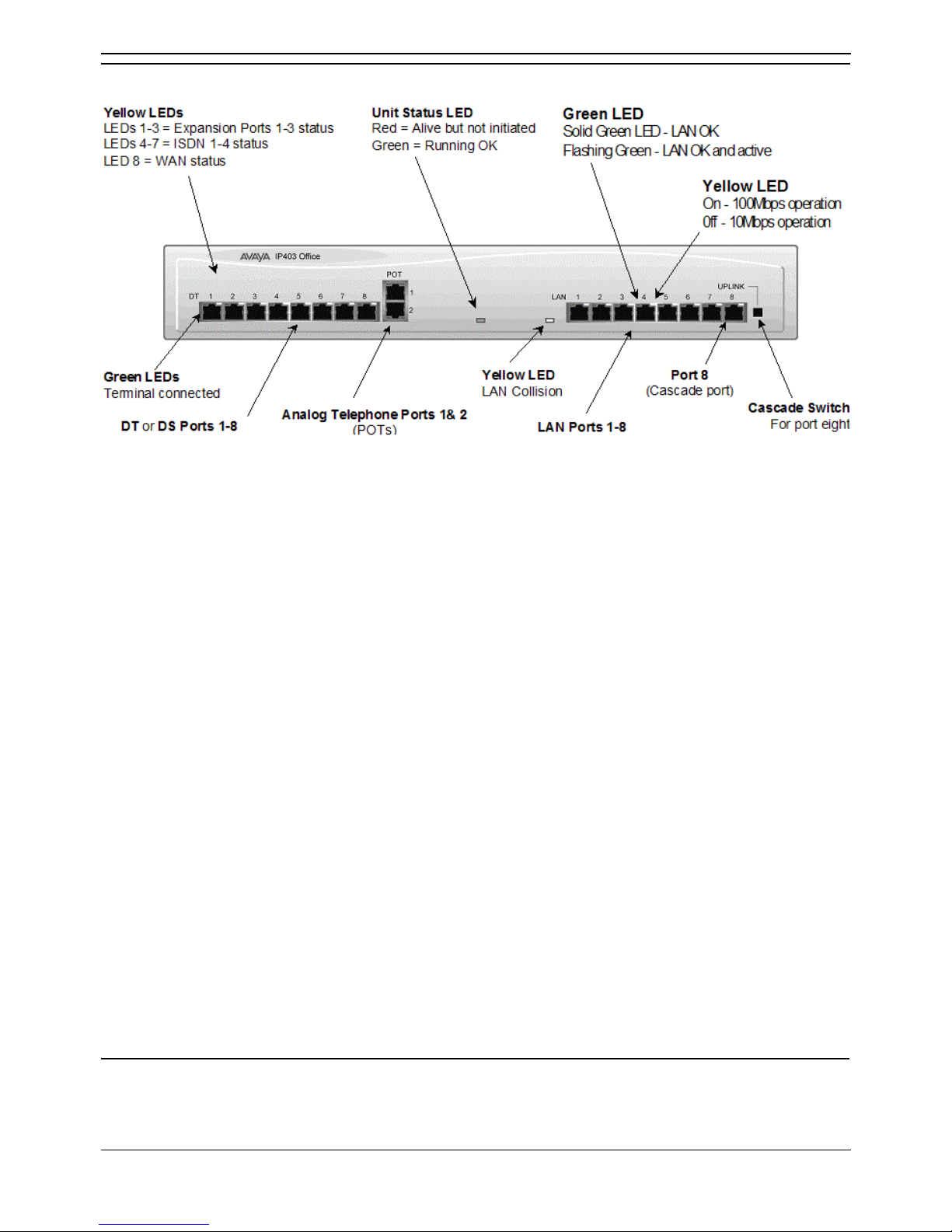
IP403 Office - Front View
• DT/DS Ports
• DT ports are for connection to Avaya 2000 series telephones.
• DS ports are for connection to Avaya 4400, 2420 and/or 6400 series telephones.
• At default DT ports are set to A-Law PCM encoding and DS ports to either A-Law or -Law
PCM encoding . However, both ports can be switched in software - refer to the
Administration Manager Manual for details). Using DT Line Cords and standard structured
wiring, these RJ45 ports can be extended to the required telephone location. In addition,
converters can be used to provide BT New Plan sockets (431A/631A) if required. When
telephones are equipped with line cords that terminate in RJ11 plugs, then pin-to-pin
RJ11/RJ45 adapters should be used.
• Plain Ordinary Telephone (POTS) Ports
These two ports are used for connection to standard analog telephones, fax machines and
modems. They must not be connect to trunks. Using standard structured wiring, these RJ45
ports can be extended to the required telephone location. Converters can be used to provide BT
New Plan sockets (431A/631A) if required. When devices are equipped with line cords that
terminate in RJ11 plugs, then pin-to-pin RJ11/RJ45 adapters should be used.
• LAN Ports
The eight auto-negotiating 10/100 BaseT LAN hub ports are used for PC and server connectivity.
They can also be used to connect to the optional IP400 WAN3 Expansion Module and IP
telephones. LAN ports allow information relating to incoming and outgoing telephone calls to be
forwarded to PC based applications. They also provide access to the router
functionality/configuration of the IP403 Office platform for both data and Voice over IP (VoIP)
calls. (Where IP telephony is required, a suitable switch LAN switch with QoS capabilities.) This
eight port auto-negotiating 10/100 BaseT LAN hub has a single MAC address (printed on the
base of the unit). Where more than eight LAN connections are required, the eighth LAN port can
be used for cascading to other hubs. The Uplink push button to the right of this port is used to
set the mode. When the Uplink switch is in the out position the port can be connected to another
hub without the need for a crossover cable, i.e. the port is an MDI type port. When the Uplink
switch is in the in position the port can be connected directly to a PC.
Cables
IP403 Office DT PRI 30 E1 & DS PRI 24 T1 are supplied with one red CAT5E cable. IP403 Office DT
BRI 8 & DS Analog 4 are supplied with four red CAT5E cables.
Page 18
IP Office Installation
Installation Manual Page 12
IP Office 2.1 40DHB0002USCL Issue 10c (11th May 2004)
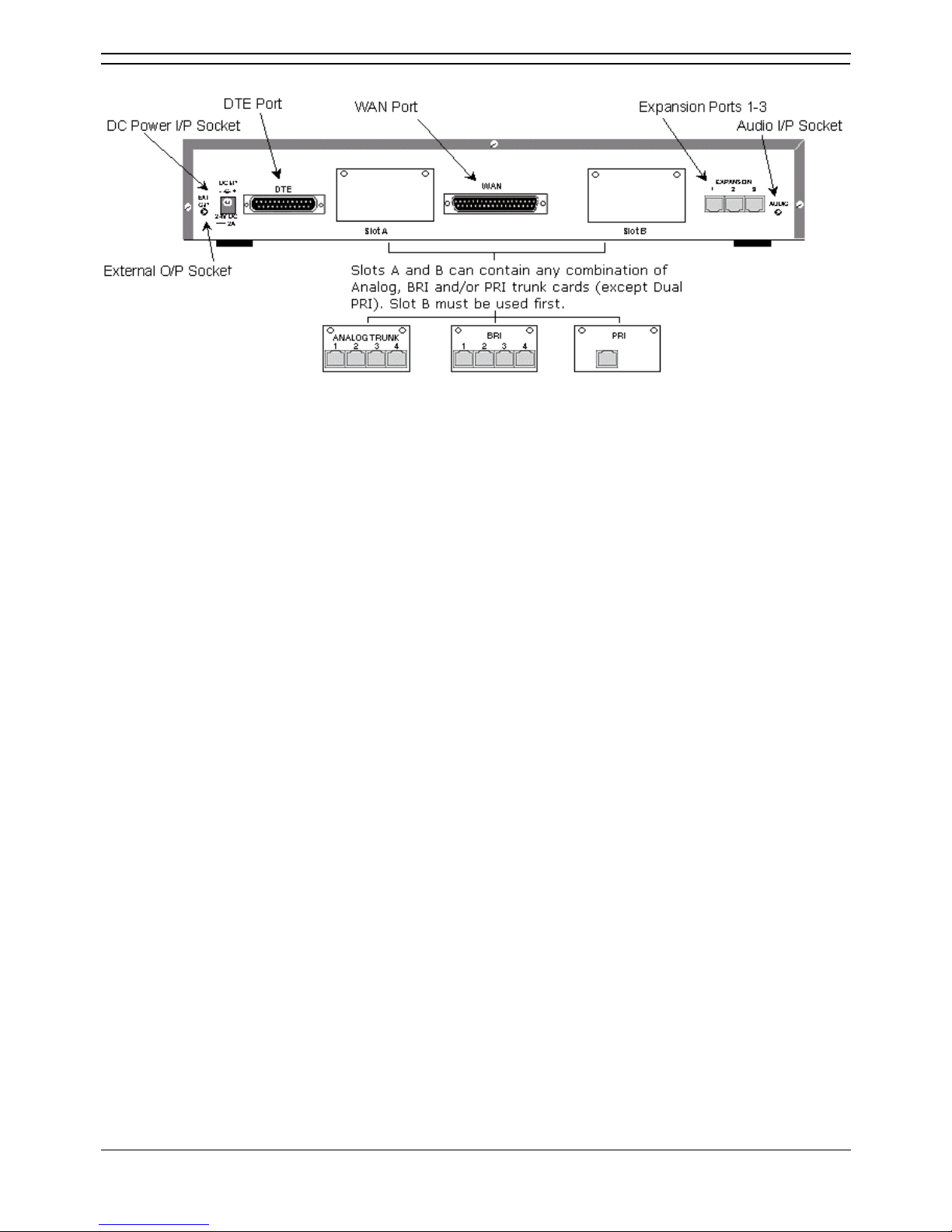
IP403 Office - Rear View
• External O/P Socket
Two relay ports that allow externally powered circuits to be controlled via a single 3.5mm stereo
jack socket.
• DC Power I/P Socket
Socket for the external 24V DC unregulated power supply (supplied with equipment).
• DTE Port
A 25-way D-type socket. Used for connection to PCs, servers and EFTPOS devices or terminals.
• Slot A/Slot B: BRI/PRI/ALOG Ports
The trunk interface modules are fitted into either Slots A or B and can consist of any combination
of:
• Quad Analog - 4 trunks.
• PRI E1/PRI E1-R2: 30 trunks.
• PRI T1: 24B trunks or 23B+1D trunks.
PRI T1 trunks support both ISDN and Analog emulation. The default setting is 23B+1D
and is switchable in the installation software to provide 24B trunks.
• Quad BRI: 8 trunks.
• WAN Port
This port supports a single synchronous data connection, which can be X.21, V.35 or V.24. The
selection of the required interface is automatically determined from the pin-out of the cable
plugged into the 'WAN' port. This cable must be connected before power is applied for auto
detection to work. Connection to a Digital Leased Circuit is made by connecting the WAN port on
the rear of the unit to the existing Network Terminating Unit (NTU) via the appropriate X.21, V.35
or V.24 cable. This interface is identical to those on the WAN3 Expansion Module.
• USB Interface: Not used.
• Expansion Ports 1-3: Used to provide access to the optional Expansion Moduleswhich allow
the IP403 Office to be expanded to 100 extensions.
• Audio I/P Socket: A single 3.5mm stereo or mono jack socket that enables input from an
external 'Music-on-Hold' source.
Page 19
IP403 Office Platform
Installation Manual Page 13
IP Office 2.1 40DHB0002USCL Issue 10c (11th May 2004)
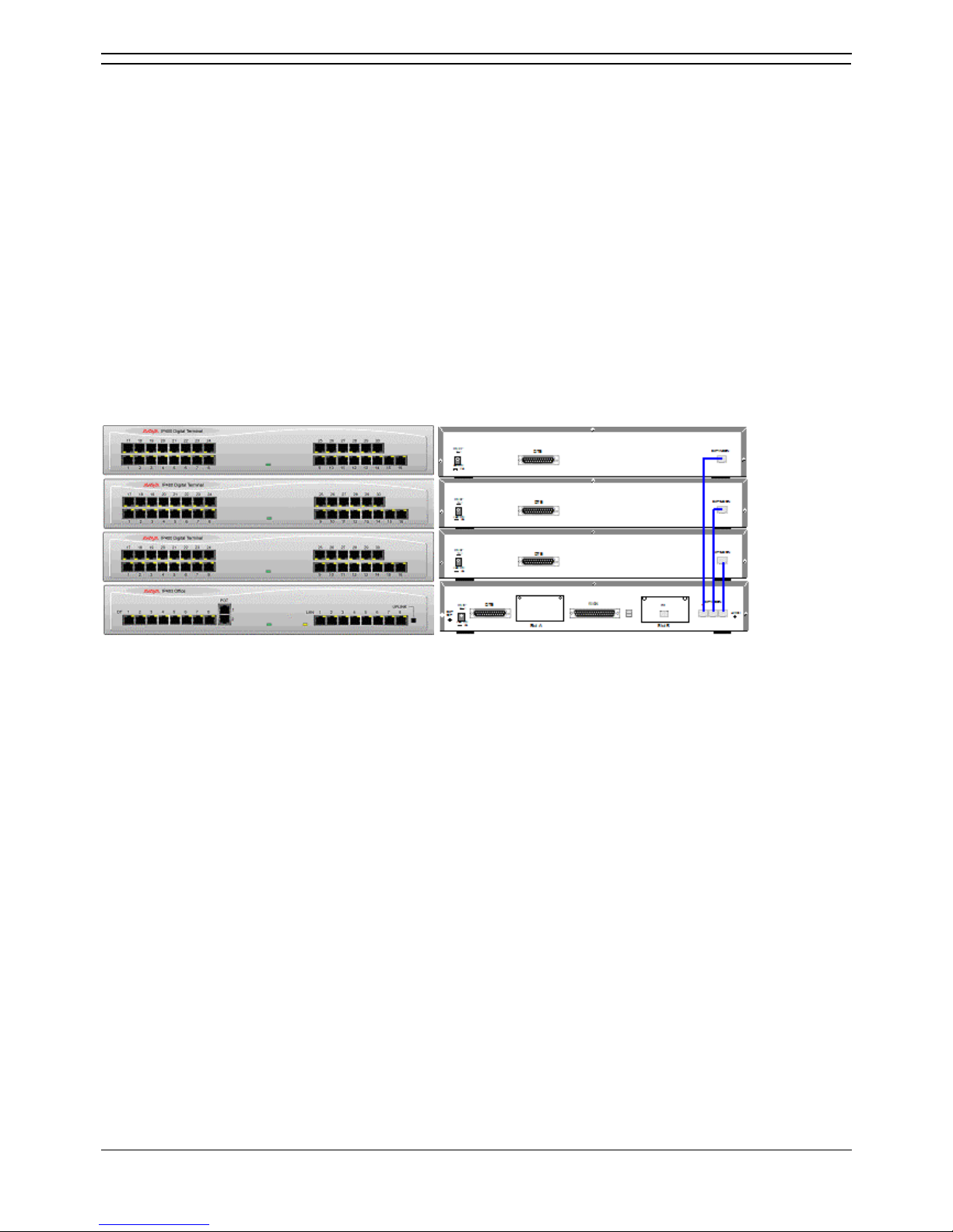
Typical Configuration
Scenario
A customer with sophisticated telephony requirements, needing 30 exchange lines and 80 Display
Terminals.
This configuration provides support for 98 Avaya 20 series digital telephones (18 spare for growth) and a
single Primary Rate ISDN connection. If growth beyond 18 users or additional line capacity were
anticipated, the IP406 Office would be considered more appropriate. Typically, a business of this size
would have a data network built using LAN switches such as the Avaya Cajun range. The IP403
Compact Office would be connected to the data network through its integral 8 port Hub, providing all
users access to the Internet and IP Office productivity applications.
Kit List
• IP403 Office DT PRI 30 E1
• 3 x IP400 Digital Terminal Module 30
• 80 x 2030 Display Terminals
Page 20

Page 21

Installation Manual Page 15
IP Office 2.1 40DHB0002USCL Issue 10c (11th May 2004)
IP406 Office Platform
IP406 Office
The IP406 Office base unit supports up to 180 extensions by using up to 6 Expansion modules.
Connection to trunks is via any two of the following integral interface modules as follows:-
• Single PRI E1/PRI E1-R2 (30 trunks) or
• Single PRI T1 (23B+1D or 24B trunks - USA only) or
• Quad BRI (8 trunks) or
• Analog 4 (loop start).
See IP400 Office Systems
for country specific variants.
An eight port auto-negotiating 10/100 BaseT LAN hub provides access to networks and/or up to eight IP
telephones. (Where IP telephones are to be used a suitable LAN switch with QoS capabilities, should be
used).
Expansion Modules
Optional Expansion Modules allow the IP406 Office to be expanded to 180 extensions. These modules
(with the exception of the WAN3 – see below) are connected via the Expansion Port sockets that are
located on the back of each unit.
Up to six, in any combination, of the following Expansion Modules can be supported by the IP406
Office base unit.
• IP400 Digital Terminal 16/30 or Digital Station 16/30
Two variants of both (16 or 30 extensions) for digital telephones. Hence, six IP400 Digital
Terminal/Station 30s will allow a maximum of 180 digital extensions.
• IP400 Phone 8/16/30
Three variants (8, 16 or 30 extensions) for analog telephones. Hence, six IP400 Phone 30s will
allow a maximum of 180 analog extensions.
• IP400 So8
An S-bus module that provides 8 Basic rate ISDN interfaces.
• IP400 WAN3
Provides support for a further 3 digital leased line (WAN) connections. These expansion modules
are connected to the IP403 Office unit via one of the LAN Ports located on the front of each unit.
• IP400 Analog Trunk 16
Provides support for up to 16 Loop Start or Ground Start analog trunks. Two power fail sockets
are also provided.
Integral Modules (Optional)
In addition the IP406 Office can be fitted with either or both of the following optional Integral Modules:
• Voice Compression Module (VCM)
Supports VoIP applications including trunking and support for IP telephones. Available in 5, 10
and 20 channel variants.
• Dual Modem Module
Allows termination of two simultaneous analog modem calls up to and including 56kbps.
Page 22
IP Office Installation
Installation Manual Page 16
IP Office 2.1 40DHB0002USCL Issue 10c (11th May 2004)
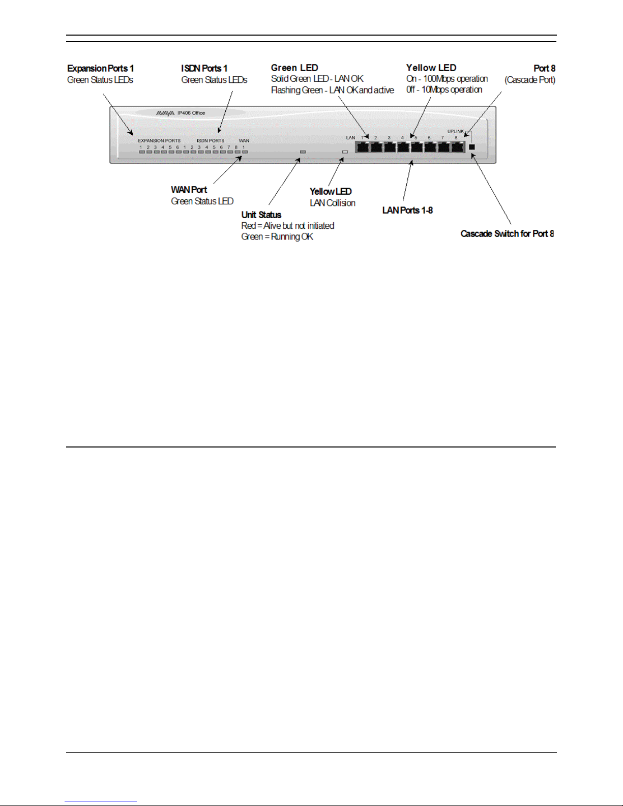
IP406 Office - Front View
• LAN Ports
The eight auto-negotiating 10/100 BaseT LAN hub ports are used for PC and server connectivity.
They can also be used to connect to the optional IP400 WAN3 Expansion Module and IP
telephones.
• LAN ports allow information relating to incoming and outgoing telephone calls to be
forwarded to PC based applications. They also provide access to the router
functionality/configuration of the IP406 Office platform for both data and Voice over IP
(VoIP) calls. (Where IP telephony is required, the hub must be connected to a suitable
LAN switch with QoS capabilities.) This eight port auto-negotiating 10/100 BaseT LAN
hub supports a single MAC address only (printed on the base of the module).
• Where more than eight LAN connections are required, the eighth LAN port can be used
for cascading to other hubs. The Uplink push button to the right of this port is used to set
the mode. When the Uplink switch is in the out position the port can be connected to
another hub without the need for a crossover cable, i.e. the port is an MDI type port.
When the Uplink switch is in the in position the port can be connected directly to a PC.
Cables
IP406 Office PRI 30 E1 & PRI 24 T1 are supplied with one red CAT5E cable. IP406 Office Analog 4 is
supplied with four red CAT5E cables. IP406 Office BRI 16 is supplied with eight red CAT5E cables.
Page 23
IP406 Office Platform
Installation Manual Page 17
IP Office 2.1 40DHB0002USCL Issue 10c (11th May 2004)
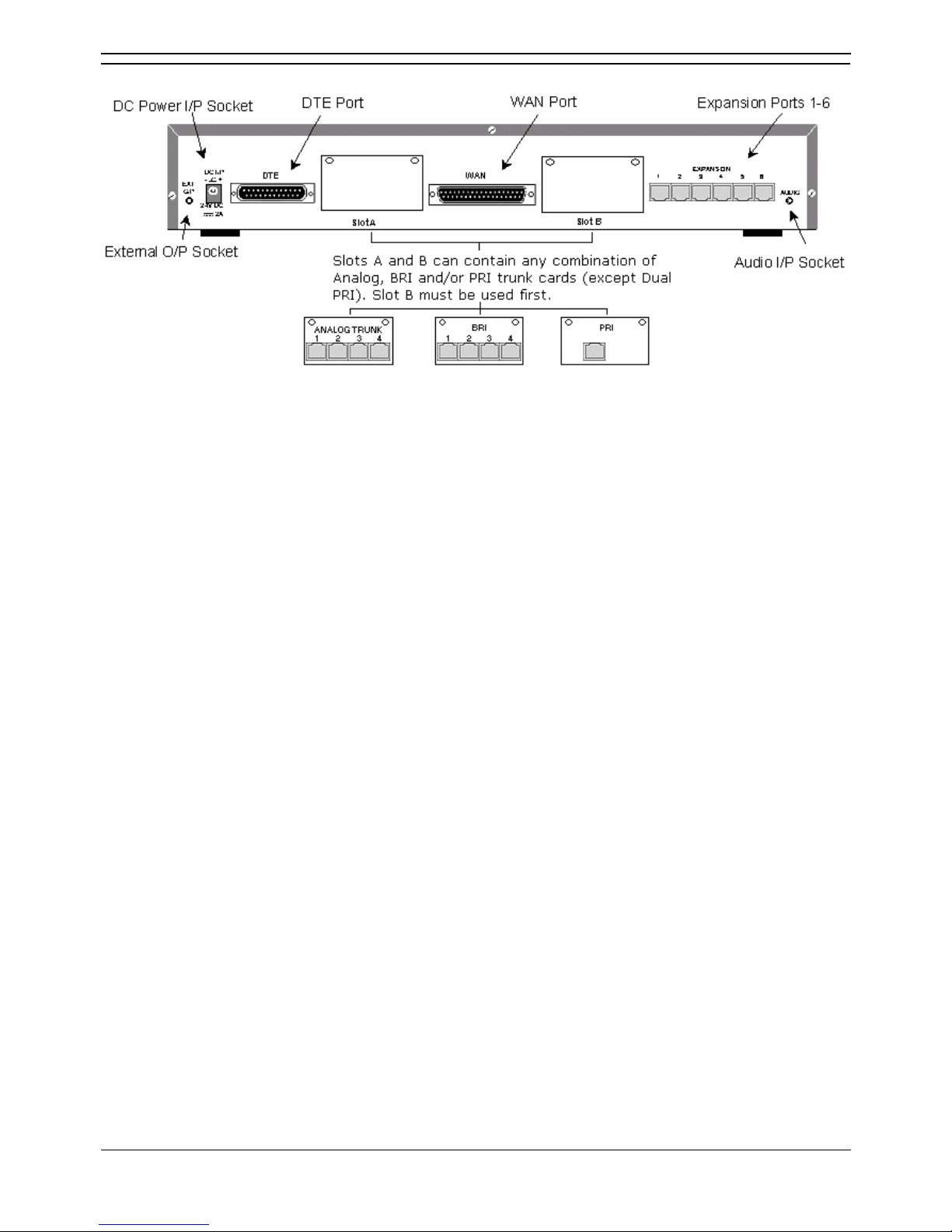
IP406 Office - Rear View
• External O/P Socket
Two relay ports that allow externally powered circuits to be controlled via a single 3.5mm stereo
jack socket.
• DC Power I/P Socket
Socket for the external 24V DC unregulated power supply (supplied with kit).
• DTE Port
A 25-way D-type socket. Used for connection to PCs, servers and EFTPOS terminals.
• Slot A/Slot B: BRI/PRI/ALOG Ports
The trunk interface modules are fitted into either Slots A or B and can consist of any combination
of:
• Quad Analog - 4 trunks.
• PRI E1/PRI E1-R2: 30 trunks.
• PRI T1: 24B trunks or 23B+1D trunks.
PRI T1 trunks support both ISDN and Analog emulation. The default setting is 23B+1D
and is switchable in the installation software to provide 24B trunks.
• Quad BRI: 8 trunks.
• WAN Port
This port supports a single synchronous data connection, which can be X.21, V.35 or V.24. The
selection of the required interface is automatically determined from the pin-out of the cable
plugged into the 'WAN' port. This cable must be connected before power is applied for auto
detection to work. Connection to a Digital Leased Circuit is made by connecting the WAN port on
the rear of the unit to the existing Network Terminating Unit (NTU) via the appropriate X.21, V.35
or V.24 cable. This interface is identical to those on the WAN3 Expansion Module.
• Expansion Ports 1-6
Used to provide access to the optional Expansion Modules which allow the IP406 Office to be
expanded to 180 extensions.
• Audio I/P Socket
A single 3.5mm stereo or mono jack socket that enables input from an external 'Music-on-Hold'
source.
Page 24
IP Office Installation
Installation Manual Page 18
IP Office 2.1 40DHB0002USCL Issue 10c (11th May 2004)
Typical Configurations
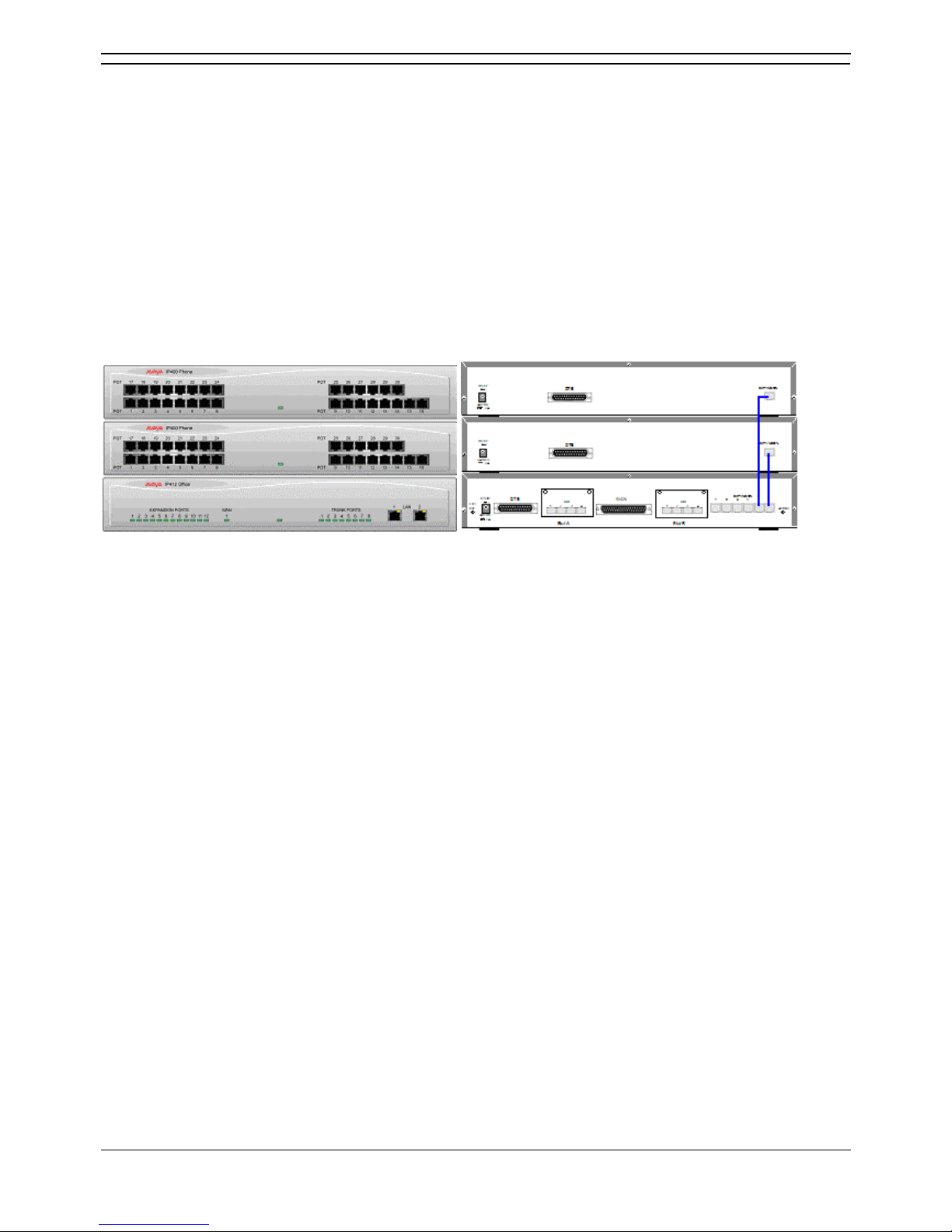
Scenario 1
A business requiring 60 analog Telephones and 8 Basic Rate ISDN lines (16 channels).
The IP406 Office BRI 16 with two IP400 Office Phone 30 modules provides the required line and
extension capacity. Through the use of PhoneManager Lite the functionality provided by the Analog
Telephones is greatly enhanced. Expansion capability for an additional 4 Modules allows the system to
be expanded to a full 180 extensions. Additional lines can be added by replacing one of the BRI
interfaces for a Primary rate.
Kit List
• IP406 Office BRI 16
• 2 x IP400 Office Phone Module 30
Page 25
IP406 Office Platform
Installation Manual Page 19
IP Office 2.1 40DHB0002USCL Issue 10c (11th May 2004)
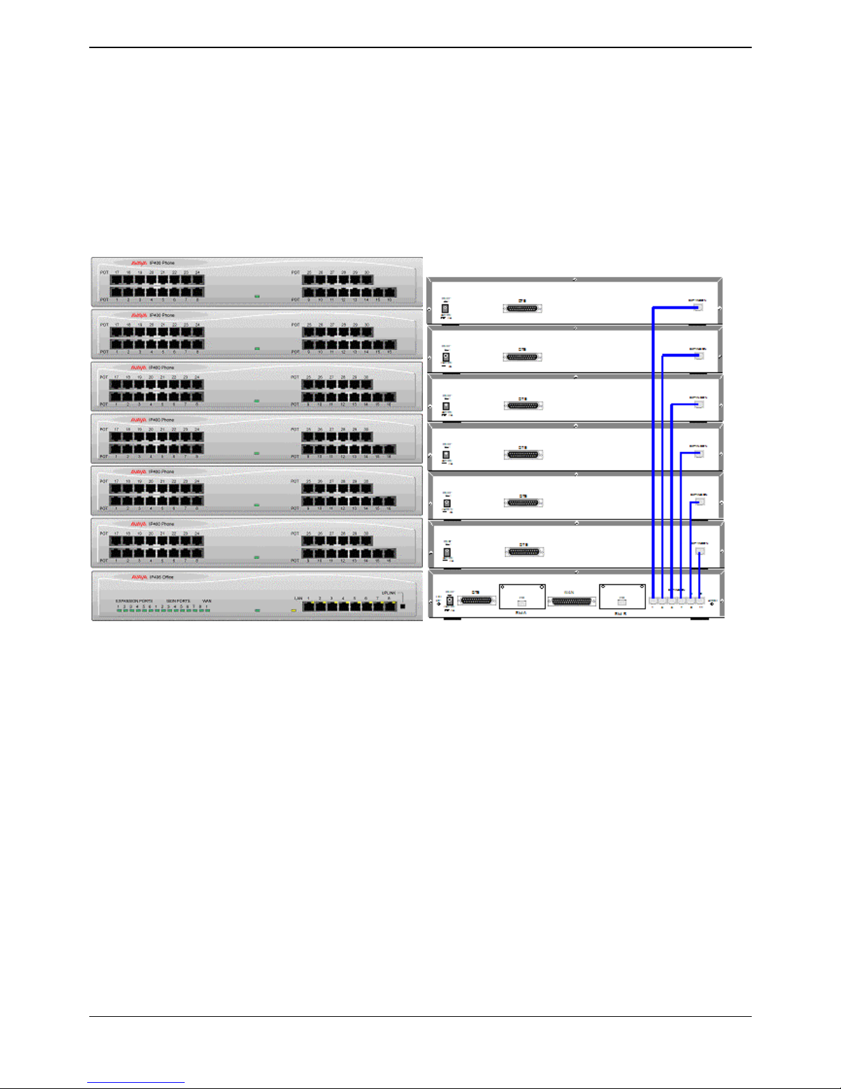
Scenario 2
A business requiring 180 analog Telephones and 60 lines.
The configuration illustrates a fully configured IP406 Office providing 180 extensions and 60 trunks.
Factory shipped with a single PRI the system is fitted with an extra trunk card in its spare slot to provide
the additional 30 lines.
Kit List
• IP406 Office PRI 30 E1 fitted with an additional IP400 IP PRI E1 trunk card
• 6 x IP400 Office Phone Module 30
Page 26

Page 27

Installation Manual Page 21
IP Office 2.1 40DHB0002USCL Issue 10c (11th May 2004)
IP412 Office Platform
IP412 Office
The IP412 Office base unit supports up to 360 extensions by using up to12 Expansion modules.
Connection to trunks is via a combination of any of the following integral interface modules :-
• Single or Dual PRI E1/PRIE1-R2 (30 or 60 trunks respectively).
• Single or Dual PRI T1 (24 or 48 trunks respectively - USA only).
• Quad BRI (8 trunks).
• Analog 4 (4 loop start trunks).
See IP400 Office Systems
for country specific variants.
Dual independent auto-negotiating 10/100 BaseT Ethernet ports provide segmented access (allows a
firewall break to be used) to the LAN. Where IP telephones are to be used a suitable LAN switch with
QoS capabilities, must be used.
Expansion Modules
Optional Expansion Modules allow the IP412 Office to be expanded to a maximum of 360 digital or
analog extensions. The Expansion Modules (with the exception of the WAN3 – see below) are
connected via the Expansion Port sockets that are located on the back of each unit.
Up to twelve, in any combination, of the following Expansion Modules can be supported by the IP412
Office base unit provided that the maximum number of extensions does not exceed 360.
• IP400 Digital Terminal 16/30 or Digital Station 16/30
Two variants of both (for 16 or 30 extensions) for digital telephones. Hence, twelve IP400 Digital
Terminal/Station modules can be fitted to allow a maximum of 360 digital extensions.
• IP400 Phone 8/16/30
Three variants (for 8, 16 or 30 extensions) for analog telephones. Hence, twelve IP400 Phone
modules can be fitted to allow a maximum of 360 analog extensions.
• IP400 So8
An S-bus module that provides 8 Basic rate ISDN interfaces.
• IP400 WAN3
Provides support for a further 3 digital leased line (WAN) connections. These expansion modules
are connected to the IP403 Office unit via one of the LAN Ports located on the front of each unit.
• IP400 Analog Trunk 16
Provides support for up to 16 Loop Start or Ground Start analog trunks. Two power fail sockets
are also provided.
Integral Modules (Optional)
In addition the IP412 Office can be fitted with either or both of the following optional Integral Modules:
• Voice Compression Module (VCM)
Provides VoIP applications including trunking and support for IP telephones. Available in 5, 10,
20 and 30 channel variants. The IP412 Office can have two VCMs (of any type).
• Dual Modem Module
Allows termination of two simultaneous analog modem calls at speeds up to and including
56kbps (V.90).
Page 28
IP Office Installation
Installation Manual Page 22
IP Office 2.1 40DHB0002USCL Issue 10c (11th May 2004)
IP412 Office - Front View
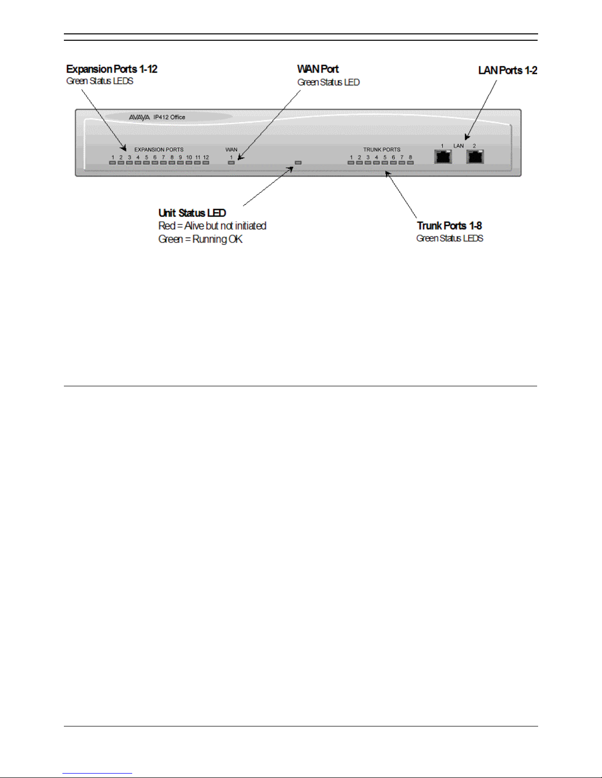
• LAN Ports
The segmented dual independent auto-negotiating 10/100 BaseT Ethernet ports are used for PC
and server connectivity. They can also be used to connect to the optional IP400 WAN3
Expansion Module and IP telephones.
Information relating to incoming and outgoing telephone calls can be forwarded to PC based applications
via these ports. These segmented Ethernet ports support separate IP and MAC addresses and hence a
Firewall break may be implemented. They also provide access to the router functionality/configuration of
the IP412 Office platform for both data and Voice over IP (VoIP) calls. Where IP telephony is required, a
suitable switch LAN switch with QoS capabilities.
Cables
IP412 Office DT PRI 30 E1 & DS PRI 24 T1 are supplied with one red CAT5E cable. IP412 Office DT
PRI60 E1 & PRI48 T1 are supplied with two red CAT5E cables.
Page 29
IP412 Office Platform
Installation Manual Page 23
IP Office 2.1 40DHB0002USCL Issue 10c (11th May 2004)
IP412 Office - Rear View
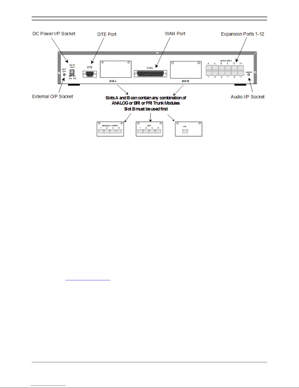
• External O/P Socket
Two relay ports that allow externally powered circuits to be controlled via a single 3.5mm stereo
jack socket.
• DC Power I/P Socket
Socket for the external 24V DC unregulated power supply (supplied with kit).
• DTE Port
A 9-way D-type socket. Used for connection to PCs, servers and EFTPOS terminals.
• BRI/PRI/ALOG Ports
The trunk interface modules are fitted into either Slots A or B as follows:
• Slot A
• Quad Analog: 4 trunks
• Quad BRI: 8 trunks
• Single or Dual PRI E1/E1-R2: 30 or 60 trunks respectively
• Single or Dual PRI T1: 24B/ 23B+1D or 48B/46B+2D trunks respectively.
• Slot B
• Single or Dual PRI E1/E1-R2: 30 or 60 trunks respectively
• Single or Dual PRI T1: 24B/ 23B+1D or 48B/46B+2D trunks respectively.
• PRI T1trunks support both ISDN and Analog emulation. The default setting is 23B+1D
(46B+2D) and is switchable in the installation software to become a 24B (48B) trunk. See
Integral Module Kits
for country specific variants.
• WAN Port
This port supports a single synchronous data connection, which can be X.21, V.35 or V.24. The
selection of the required interface is automatically determined from the pin-out of the cable
plugged into the WAN port. This cable must be connected before power is applied for auto
detection to work. Connection to a Digital Leased Circuit is made by connecting the WAN port on
the rear of the unit to the supplied Network Terminating Unit (NTU) via the appropriate X.21/V.35
/V.24 cable. This interface is identical to those on the WAN3 Expansion Module.
• Expansion Ports 1-12
Used to provide access to either optional Expansion Modules which allow the IP412 Office to be
expanded to 256 extensions or additional WAN interfaces.
• Audio I/P Socket
A single 3.5mm stereo or mono jack socket that enables input from an external 'Music-on-Hold'
source.
Page 30
IP Office Installation
Installation Manual Page 24
IP Office 2.1 40DHB0002USCL Issue 10c (11th May 2004)
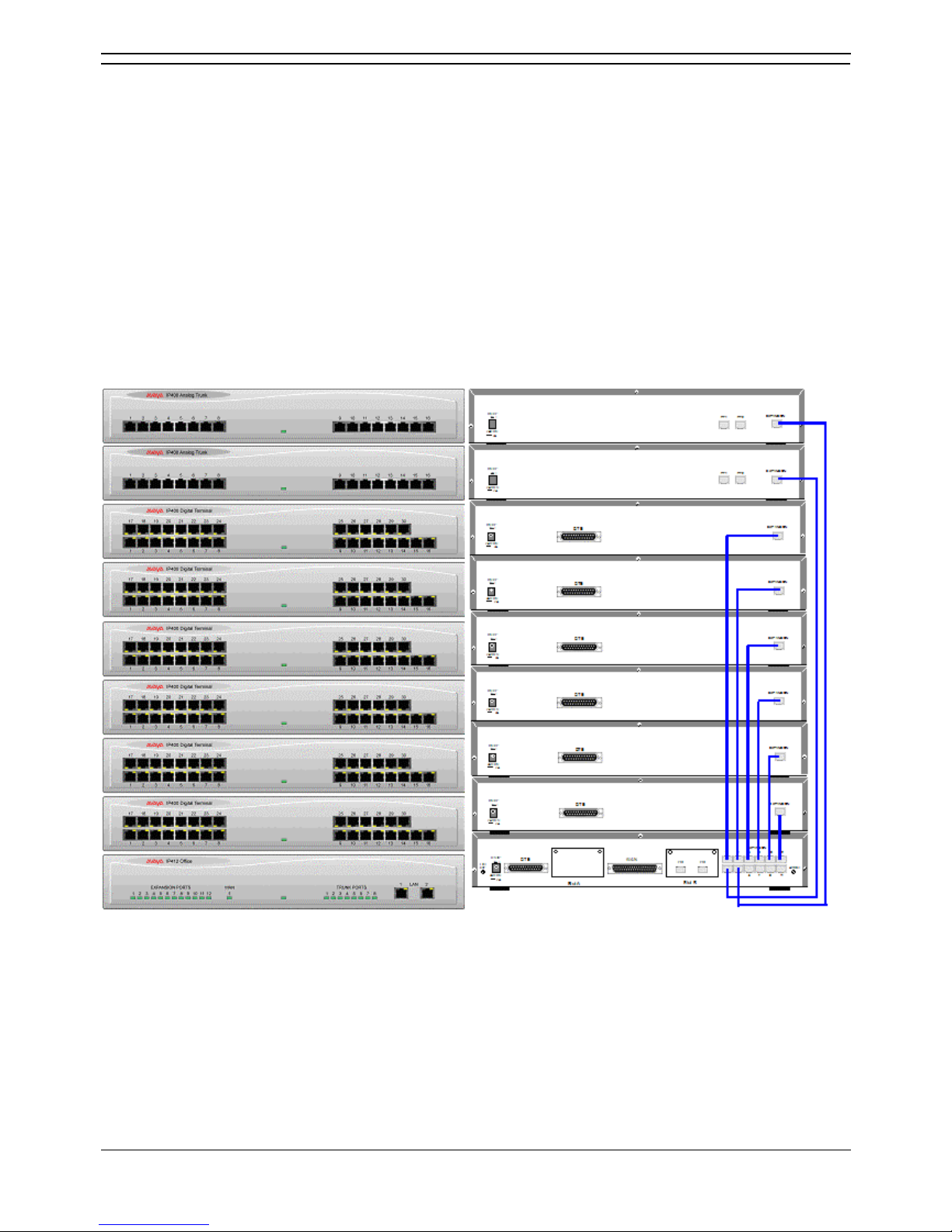
Scenario 1
A business requiring 180 Display Telephones and 96 Digital lines with 20 Analog lines for fall back
purposes in the event of the T1 service failing.
The configuration illustrates a fully configured IP412 Office providing 180 extensions and 96 digital
trunks (4 x T1) and two IP400 Office Analog Trunk 16 modules offering capacity of up to 32 analog trunk
lines. Factory shipped with a single Dual PRI T1 interface, the system is fitted with an extra trunk card in
its spare slot to provide the additional 48 lines.
Kit List
• IP412 Office PRI 48 T1
• 6 X IP400 Office Digital Station 30 Module
• 2 x IP400 Office Analog Trunk 16
• 180 x Avaya 6412 Digital Terminals
Page 31
IP412 Office Platform
Installation Manual Page 25
IP Office 2.1 40DHB0002USCL Issue 10c (11th May 2004)
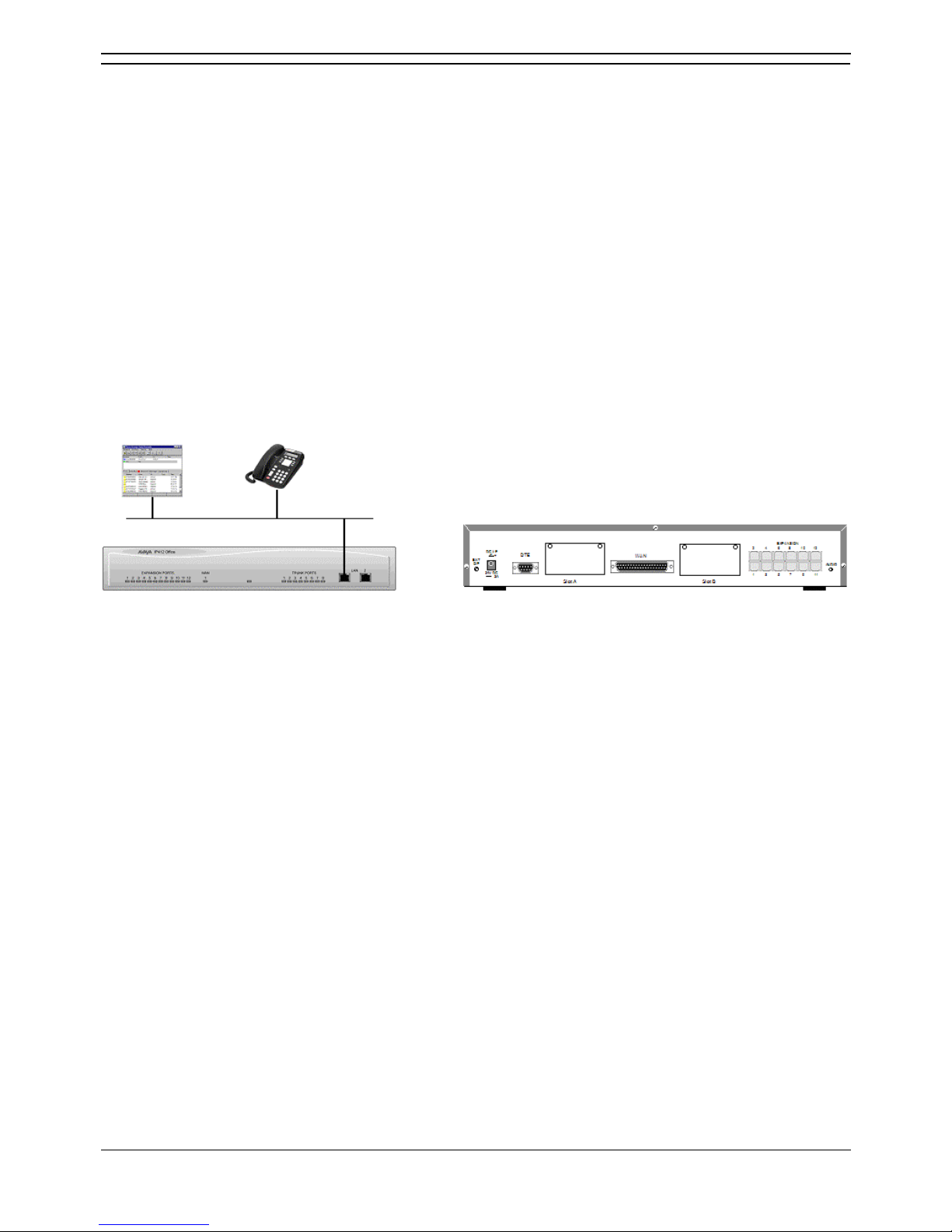
Scenario 2
A Business requiring 90 IP hardphones, 90 IP softphones and 60 lines.
This configuration illustrates an IP412 Office PRI 60 E1 fitted with two optional IP400 Office Voice
Compression Module 20s. These two internally fitted cards allow up 40 simultaneous calls to external
parties, as they are only used when an IP extension is calling a non-IP telephone or line. If less
'Gateway'ed calls are required, one of the 20 channel cards could be substituted for a smaller variant.
The IP Office softphone is 'iPhoneManager Pro' which requires two types of Licence Keys which allow
PhoneManager Lite, supplied as standard, to run as IP Extensions.
Kit List
• IP412 Office PRI 60 E1fitted with two optional IP400 Voice Compression Module 20s,
• 90 x 4612 IP Hardphones
• IP400 PhoneManager Pro RFA
• IP400 iPhoneManager Pro RFA 50
• IP400 iPhoneManager Pro RFA 40 (50+40 = 90)
Dependent upon configuration requirements, combinations of the following Expansion Modules are used
with IP Office platforms. With the exception of the WAN3 module, all of these Expansion Modules are
connected to the Expansion Ports of an IP Office platform using Expansion Interconnect Cables.
Page 32

Page 33
Installation Manual Page 27
IP Office 2.1 40DHB0002USCL Issue 10c (11th May 2004)
Expansion Modules
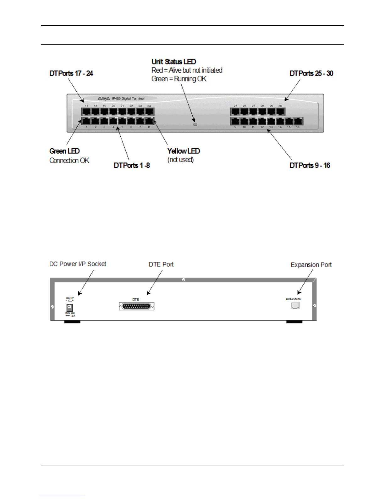
IP400 Digital Terminal 16/30
• Note
The IP400 Digital Terminal 16 Expansion Module is only equipped with the bottom row of
ports (1-16).
• DT ports are used for connection to Avaya 2000 series telephones and support either A-Law or
U-Law PCM encoding. Both DT and DS ports can be set for either U-Law or A-Law PCM
encoding. Using DT Line Cords and standard structured wiring, these RJ45 ports can be
extended to the required telephone location. In addition, converters can be used to provide BT
New Plan sockets (431A/631A) if required . When devices are equipped with line cords that
terminate in RJ11 plugs, then RJ11/RJ45 adapters should be used.
• Expansion Port
Used to connect a Digital Terminal Expansion Module to the Expansion Port of an IP Office
platform.
• DC Power I/P Socket
Socket for the external 24V DC unregulated power supply (supplied with kit).
• DTE Port
A 25-way D-type socket. Used for connection to PC (diagnostics only).
All IP400 Office Digital Terminal/Digital Station variants are supplied with one blue Expansion
Interconnect cable.
Page 34
IP Office Installation
Installation Manual Page 28
IP Office 2.1 40DHB0002USCL Issue 10c (11th May 2004)
IP400 Digital Stations 16/30
The IP400 Digital Station Expansion Module similar to the IP400 Digital Terminal Expansion Module (see
IP400 Digital Terminal 16/30
) with the exception that the Ports are labeled DS not DT and support
Avaya 6400, 2420 or 4400 series telephones.
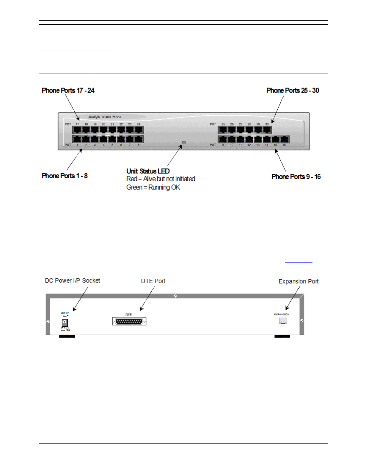
IP400 Phone 8/16/30
• Notes
The IP400 Phone 8 variant is only equipped with the bottom left row of ports. The IP400
Phone 16 variant is only equipped with the bottom row of ports.
• Plain Ordinary Telephone (POT) Ports
These ports are used for connection to standard analog telephones, fax machines and modems.
Using standard structured wiring, these RJ45 ports can be extended to the required telephone
location. Converters can be used to provide BT New Plan sockets (431A/631A) if required. When
devices are equipped with line cords that terminate in RJ11 plugs, then RJ11/RJ45 adapters
should be used. All analog telephones must conform to the port specification (see Interfaces
).
• Expansion Port
Used to connect a Phone Expansion Module to the Expansion Ports of an IP Office platform.
• DC Power I/P Socket
Socket for the external 24V DC unregulated power supply (supplied with kit).
• DTE Port
A 25-way D-type socket. Used for connection to PC (diagnostics only).
All IP400 Office Phone variants are supplied with one blue Expansion Interconnect cable.
Page 35
Expansion Modules
Installation Manual Page 29
IP Office 2.1 40DHB0002USCL Issue 10c (11th May 2004)
IP400 So8
The So8 Module is only applicable to countries that support the ETSI signaling protocol (see Expansion
Modules).
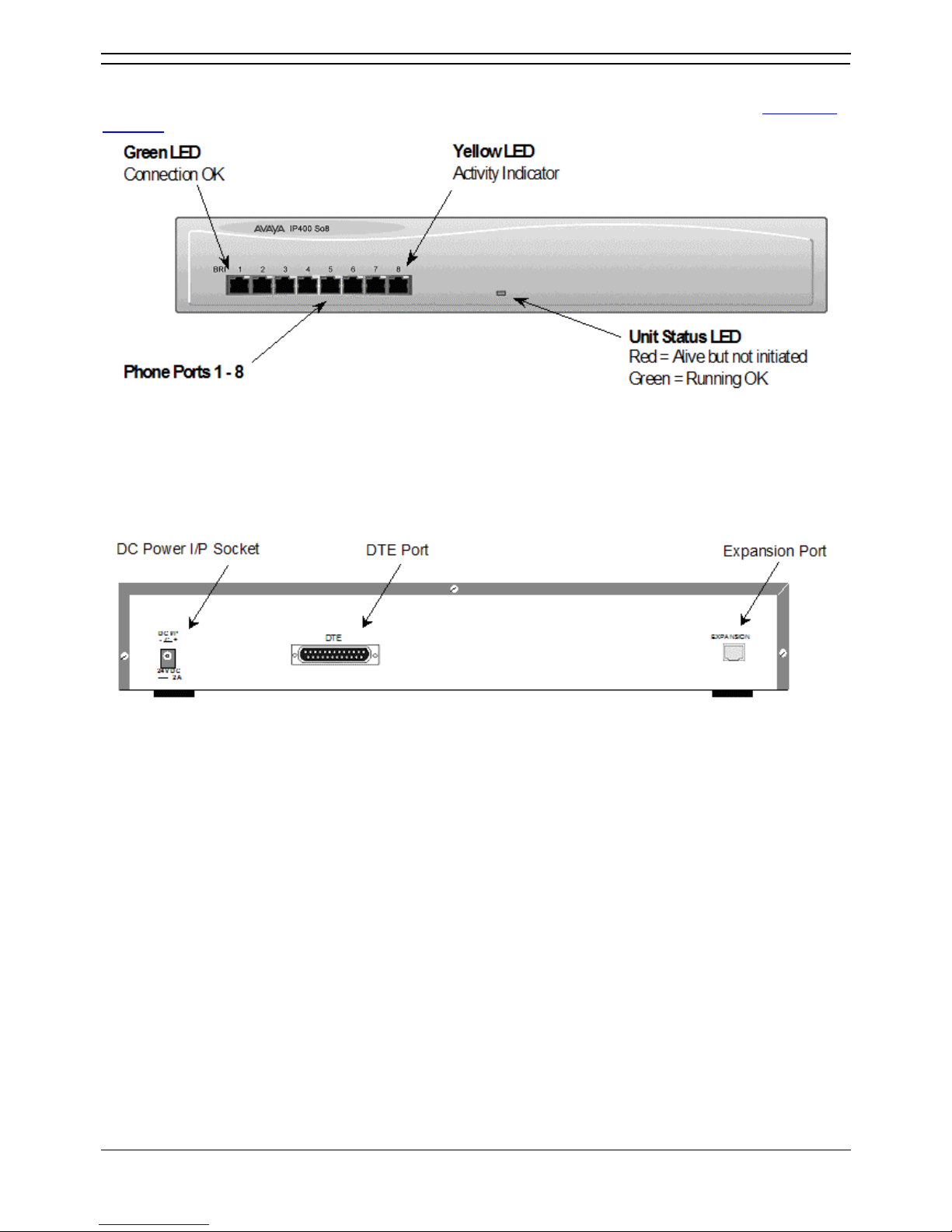
• BRI Ports
These are 64k ISDN BRI S-Bus ports and are used for connection to ISDN Telephones, Group 4
faxes, Video conferencing units, etc.
WARNING:
BRI phone ports must not be connected to the external ISDN Connections.
• Expansion Port
Used to connect a So8 Module to the Expansion Ports of an IP Office platform.
• DC Power I/P Socket
Socket for the external 24V DC unregulated power supply (supplied with kit).
• DTE Port
A 25-way D-type socket. Used for connection to PC (as a diagnostic aid).
IP400 So8 is supplied with one blue Expansion Interconnect cable.
Page 36
IP Office Installation
Installation Manual Page 30
IP Office 2.1 40DHB0002USCL Issue 10c (11th May 2004)
IP400 WAN3
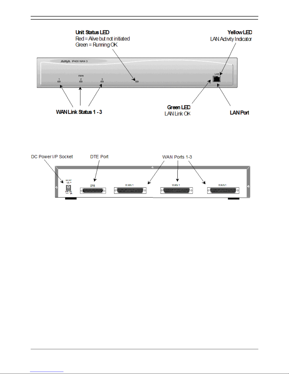
• LAN Port
The LAN Port is the expansion port and permits connection to an IP403, IP406 or IP412 Office
platform LAN Port. A LAN Interconnect cable is required for connection to an IP403 or IP406. An
IP412 requires a LAN Crossover cable.
• WAN Ports
These ports support a single synchronous data connection, which can be X.21, V.35 or
V.24/V.28. The selection of the required interface is automatically determined from the pin-out of
the cable plugged into the WAN port. This cable must be connected before power is applied for
auto detection to work. Connection to a Digital Leased Circuit is made by connecting the WAN
port on the rear of the unit to the existing Network Terminating Unit (NTU) via the appropriate
X.21, V.35 or V.24 cable. These WAN ports are identical to those on the IP403/406/412 control
units.
• DC Power I/P Socket
Socket for the external 24V DC unregulated power supply (supplied with kit).
• DTE Port
A 25-way D-type socket. Used for connection to PC (as a diagnostic aid).
IP400 WAN3 is supplied with one green LAN Interconnect cable.
Page 37
Expansion Modules
Installation Manual Page 31
IP Office 2.1 40DHB0002USCL Issue 10c (11th May 2004)
IP400 Analog Trunk 16
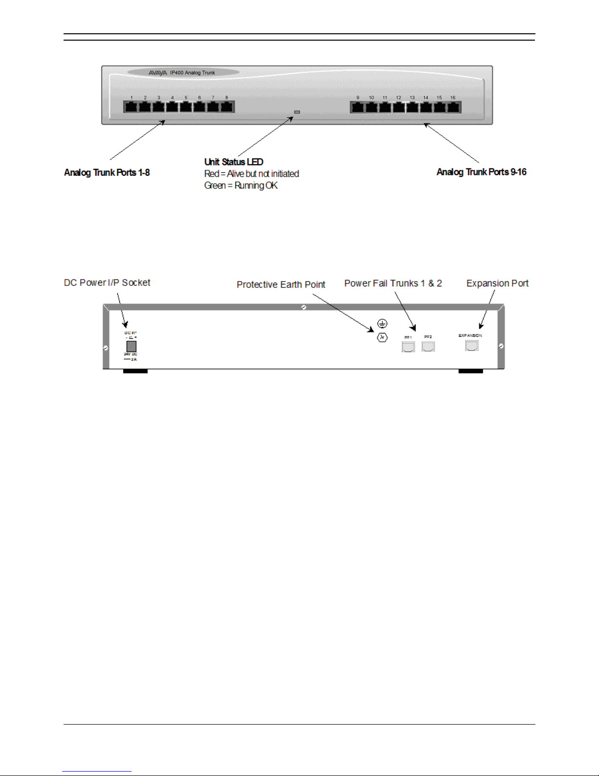
• Analog Trunk Ports
These ports are used for connection to standard analog trunks (loop start or ground start). Using
standard structured wiring, these RJ45 ports can be extended to the required trunk sockets.
Trunk ports 1 and 2 are, in the event of power failure, automatically switched to PF1 and PF2
respectively on the rear of the unit.
• Expansion Port
Used to connect the Analog Trunk Expansion Module an Expansion Ports of an IP400 Office
platform.
• DC Power I/P Socket
Socket for the external 24V DC unregulated power supply (supplied with kit).
• Power Fail Trunks
These two ports must be set and connected to Loop Start trunks only. POTs plugged into these
two sockets are mapped to trunk ports 1 & 2 such that, in the event of a mains power failure, PF1
and PF2 can operate as 'hot lines' to the emergency services (eg. 911, etc).
• Protective Grounding Point
Within the USA a protective grounding must be permanently fitted. Connection of this protective
grounding requires the use of suitable tools and must be connected at both ends before
connection is made to the telecommunications network.
IP400 Analog Trunk 16 is supplied with one blue Expansion Interconnect cable.
Page 38

Page 39

Installation Manual Page 33
IP Office 2.1 40DHB0002USCL Issue 10c (11th May 2004)
Country Variants
Overview of Country Variants
The following are lists of the country variants for each IP400 Office platform, trunk module kits, Integral
module kits and expansion modules. The PCS level for each module can be found on a label that is
stuck to the base of each module.
Throughout this section the following abbreviations are used:
• All = Everywhere.
• CALA = Caribbean/Latin America.
• CH = China.
• EU = Europe.
• JP = Japan.
• KR = Korea.
• NA = North America (USA and/or Canada).
• NZ = New Zealand.
• ROW = Rest of world (all countries excluding USA, Canada).
For countries outside North America/ CALA, use ROW variant unless stated otherwise.
Page 40
IP Office Installation
Installation Manual Page 34
IP Office 2.1 40DHB0002USCL Issue 10c (11th May 2004)
IP400 Office Systems
IP401 Compact Office
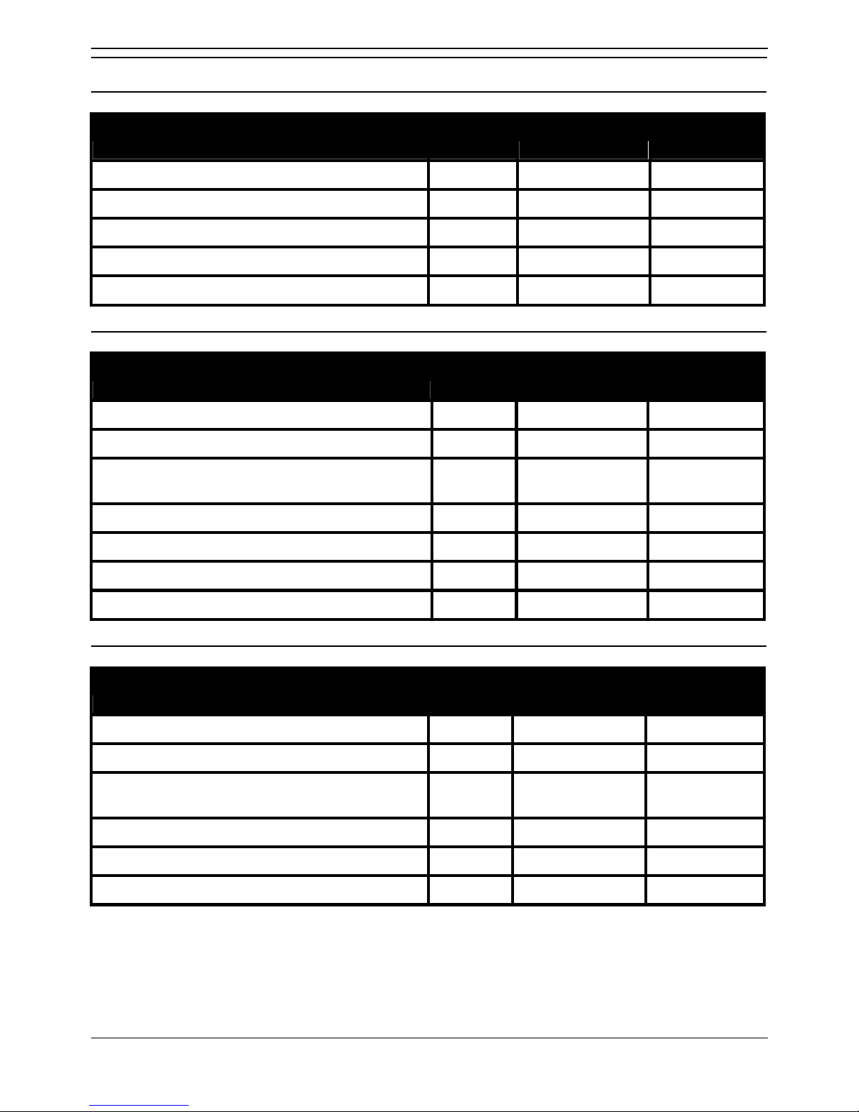
Variant A-Law/
U-Law
Country SAP Code
IP401 Compact Office DT2 A ROW 700184617
IP401 WAN Expansion kit - ROW 700185093
IP401 Memory Expansion kit - ROW 700198351
IP401 CO DT2 Expansion kit - ROW 700185085
IP401 Compact Office DT4 A ROW 700184633
IP403 Office
Variant A-Law/
U-Law
Country SAP Code
IP403 Office DT (No Trunks) A ROW/CALA 700210578
IP403 Office DT BRI 8 A ROW 700184641
IP403 Office DT PRI 30 E1 A ROW but not CH,
CALA
700184658
IP403 Office DS (No Trunks) A ROW/CALA 700234453
IP403 Office DS (No Trunks) U NA 700210610
IP403 Office DS PRI 24 T1 U NA 700184666
IP403 Office DS Analog 4 U NA 700184674
IP406 Office
Variant A-Law /U-
Law
Country SAP Code
IP406 Office (No Trunks) A ROW/CALA 700234461
IP406 Office BRI 16 A ROW 700184682
IP406 Office PRI 30 E1 A ROW but not CH,
CALA
700184690
IP406 Office (No Trunks) U NA 700210776
IP406 Office PRI 24 T1 U NA 700184708
IP406 Office Analog 4 U NA 700184716
Page 41
Country Variants
Installation Manual Page 35
IP Office 2.1 40DHB0002USCL Issue 10c (11th May 2004)
IP412 Office
Variant A-Law/
U-Law
Country SAP Code
IP412 Office (No Trunks) A ROW/CALA 700234479
IP412 Office PRI 30 E1 A ROW but not CH,
CALA
700184724
IP412 Office PRI 60 E1 A ROW but not CH,
CALA
700184732
IP412 Office (No Trunks) U NA 700210784
IP412 Office PRI 24 T1 U NA 700184740
IP412 Office PRI 48 T1 U NA 700184757
Integral Module Kits
Voice Compression Modules (VCM)
Variants Country SAP Code
IP400 VCM 5 expansion kit ALL 700185119
IP400 VCM 10 expansion kit ALL 700185127
IP400 VCM 20 expansion kit ALL 700185135
IP400 VCM 30 expansion kit ALL 700293939
Dual Modem Module
Variants Country SAP Code
IP400 Modem 2 expansion kit (V.90) ALL 700185226
Page 42
IP Office Installation
Installation Manual Page 36
IP Office 2.1 40DHB0002USCL Issue 10c (11th May 2004)
Trunk Module Kits
BRI Trunk Interface Module
Variant Country SAP Code
IP400 BRI expansion kit ROW 700185168
IP400 BRI 8 (UNI) expansion kit ROW but not CH 700262017
Analog Trunk Interface Module
Variant Country SAP Code
IP400 ANALOG 4 (LS) expansion kit NA/CALA 700185192
IP400 ANALOG 4 EU (LS) expansion kit EU 700241672
IP400 ANALOG 4 NZ (LS) expansion kit NZ 700241706
PRI Module
Variant Country SAP Code
IP400 PRI 60 E1 Expansion Kit ROW but not CH, CALA 700185184
IP4IP400 PRI 60 E1R2 RJ45 Expansion Kit CALA/KR/CH 700241649
IP400 PRI 60 E1R2 COAX Expansion Kit CALA 700241664
IP400 PRI 30 E1 Expansion Kit ROW but not CH, CALA 700185176
IP400 PRI 30 E1R2 RJ45 Expansion Kit CALA/KR/CH 700241631
IP400 PRI 30 E1R2 COAX Expansion Kit CALA 700241656
IP400 PRI 24 T1 Expansion Kit NA 700185200
IP400 PRI 48 T1 Expansion Kit NA 700185218
IP400 PRI 24 J1 Expansion Kit JP 700262033
IP400 PRI 48 J1 Expansion Kit JP 700262041
Notes:
1. For countries outside North America/CALA, use the ROW variant unless stated otherwise.
2. PRI T1trunks support both ISDN and Analog emulation. The default setting is 23B+1D and is
switchable in the installation software to become a 24B trunk.
Page 43
Country Variants
Installation Manual Page 37
IP Office 2.1 40DHB0002USCL Issue 10c (11th May 2004)
Power Supplies
Common Lump-in-Line Power Supply units are supplied with each IP Office/Expansion Module.
However, the power leads are county specific and must be ordered separately.
These power leads only applicable to IP Office base units/Expansions modules and must not be used
on the IP Office Small Edition, see the separate Installation Manual for details.
Variant Country SAP Code
IP400 Power Supply ALL 700210792
IP400 DS30 Power Lead USA USA/CALA 700261985
IP400 Power Supply 80W - China CH 700260029
IP400 DS30 Power Lead China CH 700261977
IP400 Power Lead Japan JP 700261993
IP400 Power Lead UK UK 700213374
IP400 Power Lead UK Pack 10 UK 700177557
IP400 Power Lead European CEE7/16 EU 700213382
IP400 Power Lead European CEE7/16 Pack 10 EU 700177556
IP400 Power Lead USA NA 700213390
IP400 Power Lead USA Pack 10 NA 700177558
IP400 Power Lead European CEE7/7 KR 700254519
IP400 Power Lead European CEE7/7 Pack 10 KR 700177559
IP Office Rack Mounting Kits
Rack Mounting Kit
Variant Country SAP Code
Rack Mounting kit for 19 inch racks ALL 700210800
Page 44

IP Office Installation
Installation Manual Page 38
IP Office 2.1 40DHB0002USCL Issue 10c (11th May 2004)
Expansion Modules
IP400 Phone
Variant Country SAP Code
IP400 Phone 8 ALL 700184773
IP400 Phone 16 ALL 700184781
IP400 Phone 30 ALL 700184799
IP400 Digital Terminals
Variant Country SAP Code
IP400 Digital Terminal 16 ROW 700185606
IP400 Digital Terminal 30 ROW 700185069
IP400 Digital Stations
Variant Country SAP Code
IP400 Digital Station 16 ALL 700184807
IP400 Digital Station 30 ALL 700184880
IP400 Digital Station 30 45/80W USA/CALA/CH 700260003
IP400 Analog 16 Trunks
Variant Country SAP Code
IP400 Analog Trunk 16 NA/CALA 700211360
IP400 Analog Trunk 16 EU EU 700241680
IP400 Analog Trunk 16 NZ NZ 700241698
IP400 So8
Variant Country SAP Code
IP400 So8 ALL 700185077
IP400 WAN3
Variant Country SAP Code
IP400 WAN3 ALL 700185028
IP400 WAN3 10/100 ALL 700262009
• Note: For countries outside the Americas/CALA, use ROW variant unless stated otherwise.
Page 45

Installation Manual Page 39
IP Office 2.1 40DHB0002USCL Issue 10c (11th May 2004)
Preparing for Installation
Preparing for Installation
This section reviews the requirements for installing an IP Office system. You must meet these
requirements for the system to operate safely and in the intended manner.
This section covers
:
• Tools & Parts Required.
• Space requirements
• Environmental requirements
• Power Supply requirements
Tools & Parts Required
• General
• Pozidrive No. 1 screwdriver for removal of unit covers.
• Cutter/knife for cable ties.
• Cable ties - 3mm x 50mm.
• Pozidrive No. 4 screwdriver for Analog Trunk 16 expansion module grounding post.
• Note:
In addition, ensure that you have sufficient cables that are not supplied with the
modules, e.g. Line Cords for structured cabling and power supply cables.
• Programming
These are the tools required for programming of a newly installed IP Office system.
• PC running Windows 98/2000/ME/XP or NT with the following specification: Intel Pentium
ll 333Mhz or faster, 100MB HD space, CD-ROM drive, COM port, terminal emulation (e.g.
HyperTerminal) and a super VGA Monitor (set to 1024x768).
• PC with a LAN card with either a fixed IP address (allocated by your system
administrator) or be using DHCP to obtain an IP address.
• IP Cat. 5E patch cable (red - supplied with control unit).
• IP Office Administration CD (supplied with control unit).
• IP Office Manager Application Manual (supplied on CD with system).
• IP Office Feature Key (where software that requires a Licence Key is to be installed).
Page 46

IP Office Installation
Installation Manual Page 40
IP Office 2.1 40DHB0002USCL Issue 10c (11th May 2004)
Space requirements
Check that the planned location meets the following requirements.
• Height :
• A IP401 Compact Office module is 71mm (2.8 inches) high.
• IP403, 406, 412 and all Expansion modules are 71mm(2.8 inches) high. Hence the total
height of a system is the number of modules multiplied by 71mm (2.8 inches).
• Width :
• A IP401 Compact Office module is 255mm (10 inches) wide.
• IP403, 406, 412 and all Expansion modules are 445mm (17.5 inches) wide.
• Depth :
• A IP401 Compact Office module is 235mm (9.3 inches) deep.
• IP403, 406, 412 and all Expansion modules are 245mm (9.7 inches) deep.
• IP403, IP406, IP412 and Expansion modules can be mounted in 19" racks (see Rack
Mounting Assembly Instructions).
• When modules are free standing (ideally mounted one upon another), allow a
minimum clearance of 50mm (20 inches) either side for cable trunking.
• Check there is suitable lighting for installation, system programming and future
maintenance.
• Check that there is sufficient working space for installation and future maintenance.
• Ensure that likely activities near the system will not cause any problems, e.g. access
to and maintenance of any other equipment in the area.
Page 47

Preparing for Installation
Installation Manual Page 41
IP Office 2.1 40DHB0002USCL Issue 10c (11th May 2004)
Environmental requirements
The planned location must meet the following requirements:
• Check that the area is a well ventilated area, having a temperature range of 0°C to +40°C and a
humidity range of 10% to 95% non-condensing.
• Check there are no flammable materials in the area.
• Check there is no possibility of flooding.
• Check that no other machinery or equipment needs to be moved first.
• Check that it is not an excessively dusty atmosphere.
• Check that the area is unlikely to suffer rapid changes in temperature and humidity.
• Check for the proximity of strong magnetic fields, sources of radio frequency and other electrical
interference.
• Check there are no corrosive chemicals or gasses.
• Check there is no excessive vibration or potential of excessive vibration, especially of the cabinet
mounting surface.
• Check that, for the USA only, where telephones are installed in another building, that the
appropriate IROB protectors are fitted (see Out of Building Telephone Installation
).
IMPORTANT SAFETY INSTRUCTIONS
When using your telephone equipment, basic safety precautions should always be followed to reduce
the risk of fire, electric shock and injury to persons, including the following:
1. Do not use this product near water, for example, near a bath tub, wash bowl, kitchen sink or
laundry tub, in a wet basement or near a swimming pool.
2. Avoid using a telephone (other than a cordless type) during an electrical storm. There may be a
remote risk of electric shock from lightning.
3. Do not use the telephone to report a gas leak in the vicinity of the leak.
4. Use only the power cord and batteries indicated in this manual. Do not dispose of batteries in a
fire. They may explode. Check with local codes for possible special disposal instructions.
SAVE THESE INSTRUCTIONS.
Page 48

IP Office Installation
Installation Manual Page 42
IP Office 2.1 40DHB0002USCL Issue 10c (11th May 2004)
Power Supply requirements
IP Office Base Units and Expansion Modules should only be connected to a clean power supply or a
UPS.
Check the following:
• IP Office Base Unit and Expansion Modules
IP Office modules require a separate switched mains supply. Power on the Expansion Modules
first. If the main IP Office Module does not detect an item at power on, it will never use it. If
power is switched on from a central point for all modules, then, as the main unit is the slowest to
start, this will be taken care of automatically.
• Standard Lump-in-Line Power Supply units are supplied with each IP Office/Expansion
Module. However, for IP400 Digital Station 30 Expansion Modules, that use more than ten
4424 terminals, the 80W Lump-in-Line Power Supply must be used. This must be
ordered separately (see Power Supplies
).
• Power leads are country specific and must be ordered separately (see Power Supplies).
• CAUTION
The Lump-in-Line PSU's supplied with each IP Office module must only be connected to a
50/60Hz, 100-240V power source.
• UPS Equipment
The use of UPS's to support the IP Office system during mains power failure is highly
recommended. Such equipment also provides mains conditioning. Contact Avaya for details of
preferred and tested suppliers and models.
Page 49
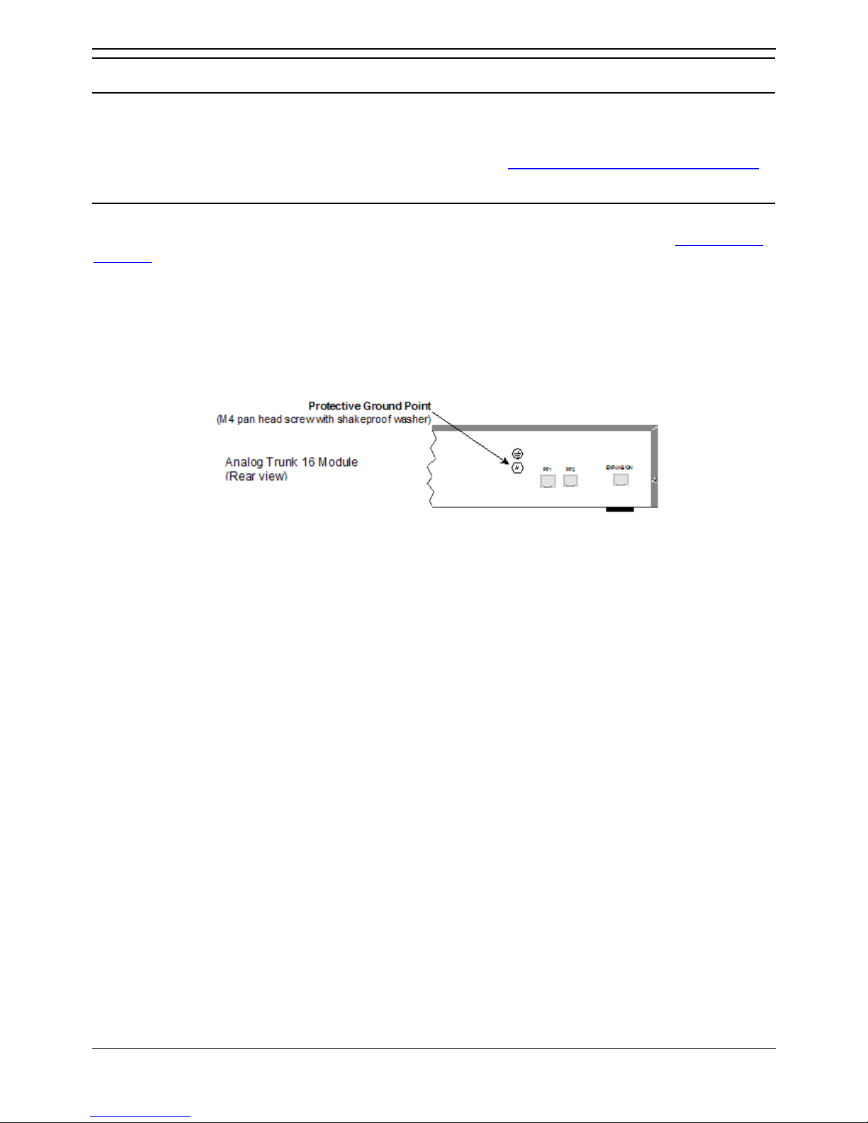
Preparing for Installation
Installation Manual Page 43
IP Office 2.1 40DHB0002USCL Issue 10c (11th May 2004)
Grounding
Grounding
Provision is made for both protective ground (earthing) and functional ground (earthing). In addition,
where the installation of telephone and/or other standard (tip/ring) devices in another building is required,
In-Range-Out-Of-Building (IROB) protectors must be fitted (see Out of Building Telephone Installations
).
Protective Ground
A protective ground must be permanently fitted to IP400 Analog Trunk 16 modules (see IP400 Analog
Trunk 16). Connection of this protective ground requires the use of suitable tools and must be
connected at both ends before connection is made to the telecommunications network.
To connect the protective ground:
1. Attached one end of a #14 AWG (minimum) solid insulated cable (sleeve must be green/yellow)
to the Protective Ground Point as shown below. Ensure that the Ground Post securing screw is
fully tightened.
2. Connect, using a fastening that satisfies local regulations, the other end of the wire to the
approved protective ground.
Page 50
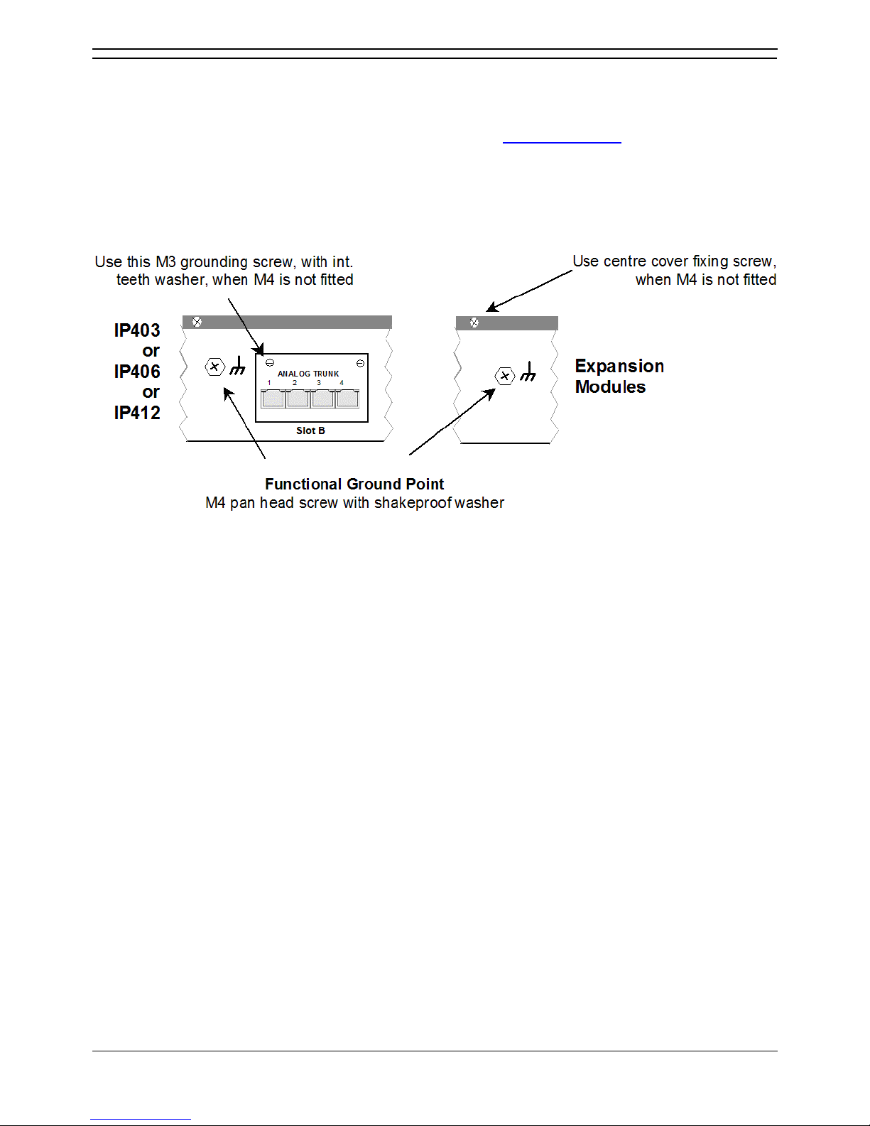
IP Office Installation
Installation Manual Page 44
IP Office 2.1 40DHB0002USCL Issue 10c (11th May 2004)
Functional Ground
To ensure proper operation of the IP Office equipment, functional grounding is required:
• Caution
This functional ground is not a protective ground – see Protective Ground
for protective
grounding.
On some models of the units/expansion modules, there may not be a specific M4 functional ground
point. In which case use either the Trunk module kit fixing screw or the top cover center fixing screw as
shown below:
To connect the functional ground:
Attached one end of a #14 AWG (minimum) solid insulated cable (sleeve must not be
green/yellow) to the grounding screw and fully tightened.
Connect, using a fastening that satisfies local regulations, the other end of the wire to the approved
ground, such as building steel or an earthed metal cold water pipe.
Page 51
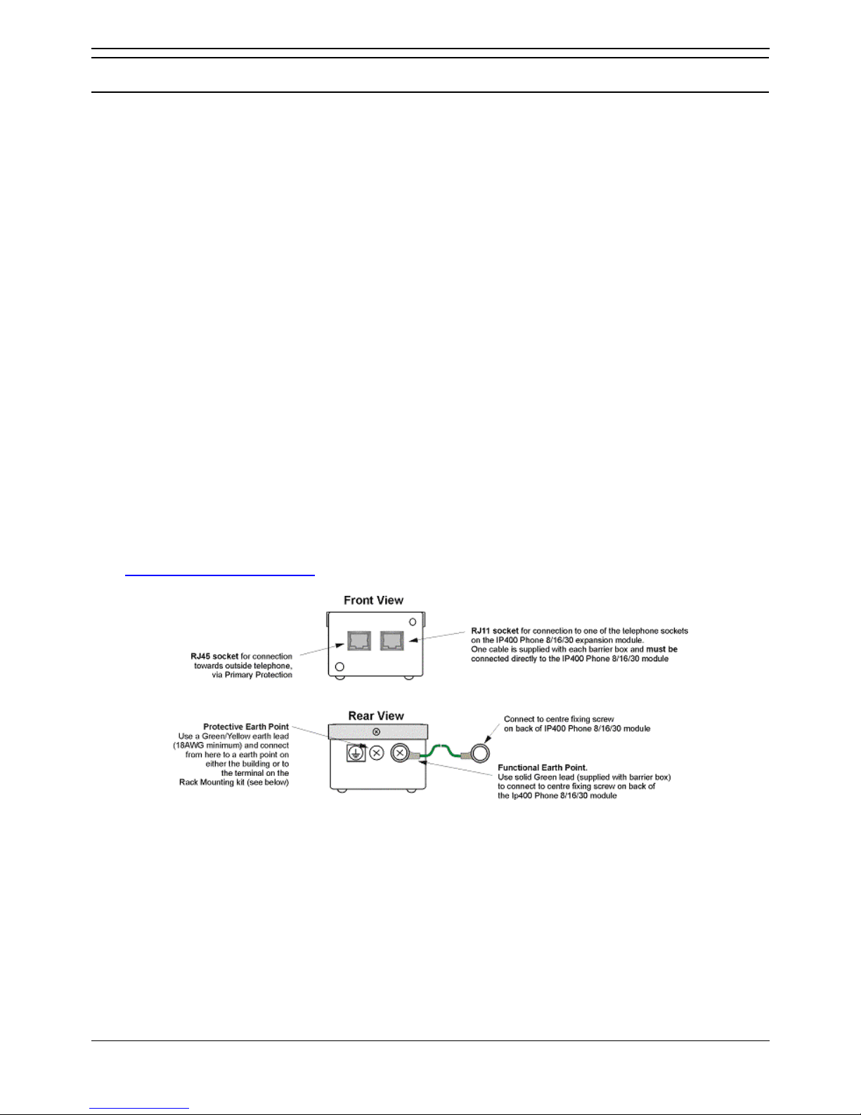
Preparing for Installation
Installation Manual Page 45
IP Office 2.1 40DHB0002USCL Issue 10c (11th May 2004)
Out of Building Telephone Installations
Out of Building Telephone Installations
Installation of telephone and/or other standard (tip/ring) devices that are external to the building housing
the Avaya IP Office or in another building require In-Range-Out-Of-Building (IROB) protectors to protect
the control unit and device from electrical surges. These must be fitted as follows:
• System telephone: Two IROB protectors
• Standard telephone: Two IROB protectors plus one carbon block protector.
Primary protection must be provided at the point where the cable enters the building. This should be
three point protection (tip, ring and ground). Typically this would be gas tube protection provided by the
local telephone company. The ground wire must be thick enough to handle all the lines being affected by
indirect strike at the same time.
• CAUTION - All cabling between buildings must not be exposed. E.g. cabling between buildings
must be carried in suitably earthed ducting; ideally underground.
Three versions of IROBs are available as follows :
• 146C - Trunks - SAP code 407228923
• 146E - TDL - SAP code 407568161
• IP400 Phone Barrier Box - SAP code 700293897
Installation of a Contact Closure Adjunct controlled device outside the building requires a 146G Surge
Protector – SCL/8 to protect the control unit from electrical surges.
Install the 146C and 146E IROBs as per the instructions supplied with the IROBs.
Avaya IP400 Phone Barrier Boxes must only be used in conjunction with UL Listed Avaya IP400 Phone
8/16/30 modules.
Where more than three Avaya IP400 Phone Barrier boxes are to be used, they must be rack mounted
(see Rack Mounting Barrier Boxes
). For non-rack mounting of the Avaya IP400 Phone Barrier Box,
proceed as follows:
Notes
1. The following wires must be kept apart, e.g. not routed in the same bundle:
• Earth lead from the barrier box to the IP400 Phone 8/16/30.
• Internal wires, e.g. wires going directly to the IP400 Phone 8/16/30.
• Wires from external telephone going directly to the barrier boxes.
2. The Avaya IP400 Phone Barrier Box will not connect the ringing capacitor in the UK, hence a
Master socket is required.
CAUTIONS
1. The analog ports on the front of the IP403 must not be used for lines external to the building.
2. The Avaya IP400 Phone Barrier Box must not be connected to the analog trunk lines
Page 52
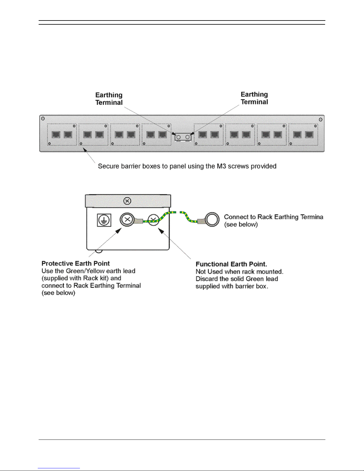
IP Office Installation
Installation Manual Page 46
IP Office 2.1 40DHB0002USCL Issue 10c (11th May 2004)
Rack Mounting Barrier Boxes
Where more than three Avaya IP400 Phone Barrier Boxes are to be used they must be rack mounted.
Rack mounting kits are available (SAP Code 700293905) for mounting eight Avaya IP400 Phone Barrier
Boxes. A maximum of 16 Avaya IP400 Phone Barrier Boxes (using two Rack kits) can be connected to
one IP400 Phone 30 module. To rack mount up to eight Avaya IP400 Phone Barrier Boxes into a rack,
perform the following:
1. Mount the Barrier boxes in the rack as shown below.
2. For each Barrier Box, discard the solid green earth wire and connect the green/yellow earth wire
to the Protective Earth Point on the back of the Barrier Box.
Page 53
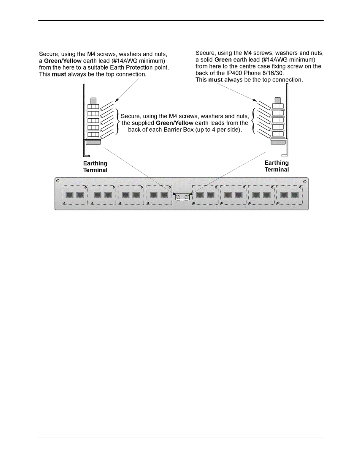
Preparing for Installation
Installation Manual Page 47
IP Office 2.1 40DHB0002USCL Issue 10c (11th May 2004)
3. Connect the earth leads as follows:
Notes
1. The following wires must be kept apart, e.g. not routed in the same bundle:
• Earth lead from the barrier box to the IP400 Phone 8/16/32.
• Internal wires, e.g. wires going directly to the IP400 Phone 8/16/32.
• Wires from external telephone going directly to the barrier box(es).
2. The Avaya IP400 Phone Barrier Box will not connect the ringing capacitor in the UK, hence a
Master socket is required.
CAUTION
1. The analog ports on the front of the IP403 must not be used for lines external to the building.
Page 54

Page 55
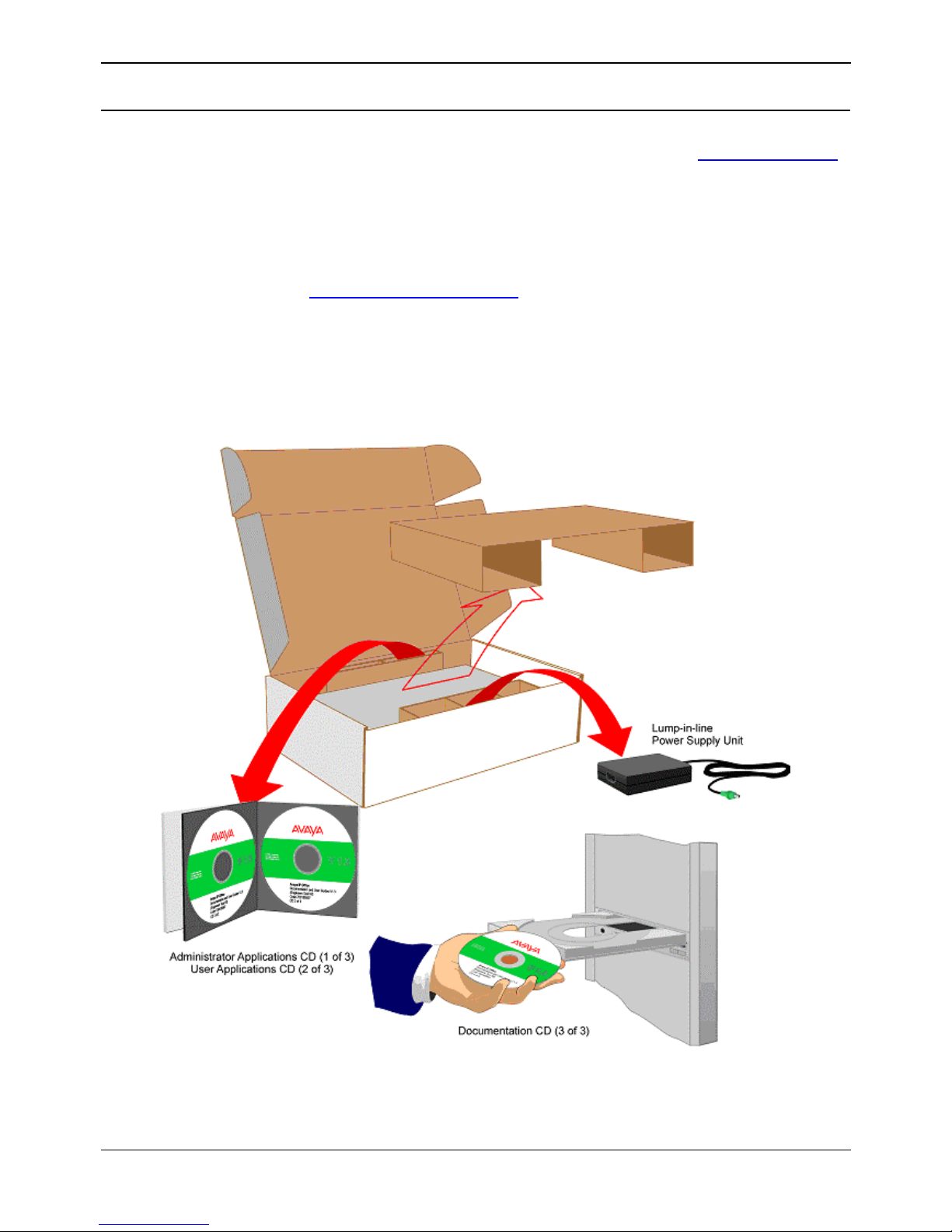
Installation Manual Page 49
IP Office 2.1 40DHB0002USCL Issue 10c (11th May 2004)
Installing a New System
Unpacking
Before proceeding with installation, ensure that you have read the notes covered in Expansion Modules
above.
Unpacking and checking :
1. Before unpacking check for any signs of damage that has occurred during transit. If any damage
exists bring it to the attention of the carrier.
2. Check all cartons against the packing slip and ensure that you have the correct item as per the
country variants (see Overview of Country Variants
). Report any errors or omissions to the
equipment supplier.
3. While unpacking the equipment, retain all the packaging material. Fault returns are accepted only
if repackaged in the original packaging.
4. Visually inspect each item and check that all the necessary documentation and accessory items
have been included. Report any errors or omissions to the dealer who supplied the equipment.
5. Ensure you read and understand any documentation included with any item.
Page 56
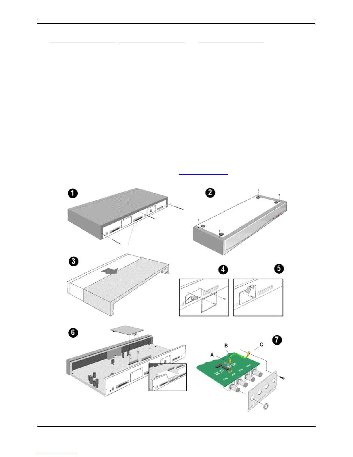
IP Office Installation
Installation Manual Page 50
IP Office 2.1 40DHB0002USCL Issue 10c (11th May 2004)
Trunk Interface Modules (BRI/PRI/ANALOG4)
See IP403 Office - Rear View, IP406 Office - Rear View and IP412 Office - Rear View for details of
which trunk interface modules may be fitted.
1. CAUTION - While installing, ensure that you wear a ground wrist strap that is connected to a
suitable grounding point.
2. Remove the three fixing screws on the rear of cover.
3. Turn the unit over and remove the four fixing screws from the base.
4. Slide the cover from the unit.
5. Remove the two blanking plate securing screws and remove blanking plate.
6. Insert the trunk module and secure with the two screws.
7. Mount the trunk module in position as shown below and secure with the two snap-in spacers
(except for PRI E1/R2).
8. For CALA only: On the PRI E1/R2 coaxial module, use the shorting blocks (A) to connect Rx1 to
GND, Tx1 to GND and/or Rx2 to GND, Tx2 to GND as required. Connect the earthing strap
spade end (B) to the spade connection on the board and the other end (C) to the chassis with the
long securing screw (both of which are supplied with the kit).
9. Where required, fit the functional ground (see Functional Ground
).
10. Replace cover and secure with the seven fixing screws.
Page 57
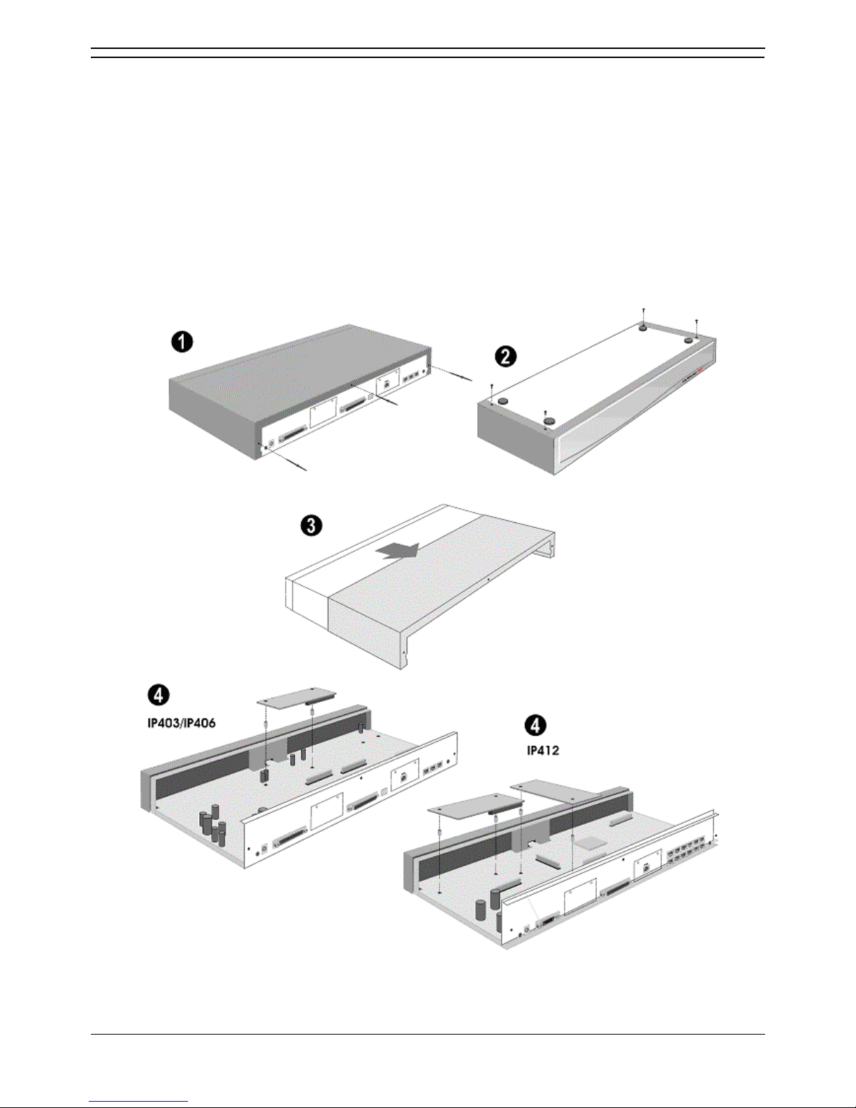
Installing a New System
Installation Manual Page 51
IP Office 2.1 40DHB0002USCL Issue 10c (11th May 2004)
Installation of Voice Compression Modules (VCM)
The IP403 and 406 can support one VCM5, 10 or 20 but not the VCM30. The IP412 can support two
VCMs of any type. VCMs are fitted to as follows:
1. CAUTION - While installing, ensure that you wear a ground wrist strap that is connected to a
suitable grounding point.
2. Remove the three fixing screws on the rear of cover.
3. Turn the unit over and remove the four fixing screws from the base.
4. Slide the cover from the unit.
5. Mount the VCM in position as shown below and secure with the two snap-in spacers. The IP412
can support a second VCM; the first module can be mounted in either position.
6. Replace cover and secure with the seven fixing screws.
Page 58
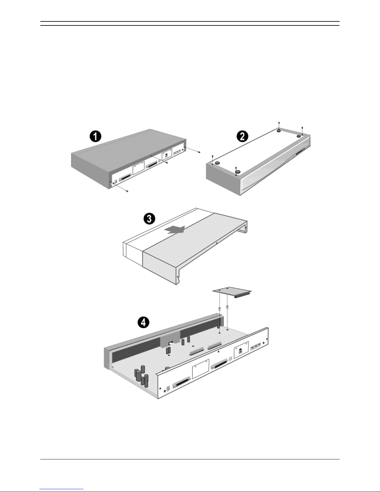
IP Office Installation
Installation Manual Page 52
IP Office 2.1 40DHB0002USCL Issue 10c (11th May 2004)
Dual Modem Module
An optional Dual Modem Module is fitted to an IP Office base unit as follows:
1. CAUTION - While installing, ensure that you wear a ground wrist strap that is connected to a
suitable grounding point.
2. Remove the three fixing screws on the rear of cover.
3. Turn the unit over and remove the four fixing screws from the base.
4. Slide the cover from the unit.
5. Mount the module in position as shown below and secure with the two snap-in spacers.
6. Replace the cover and secure with the seven fixing screws.
Page 59
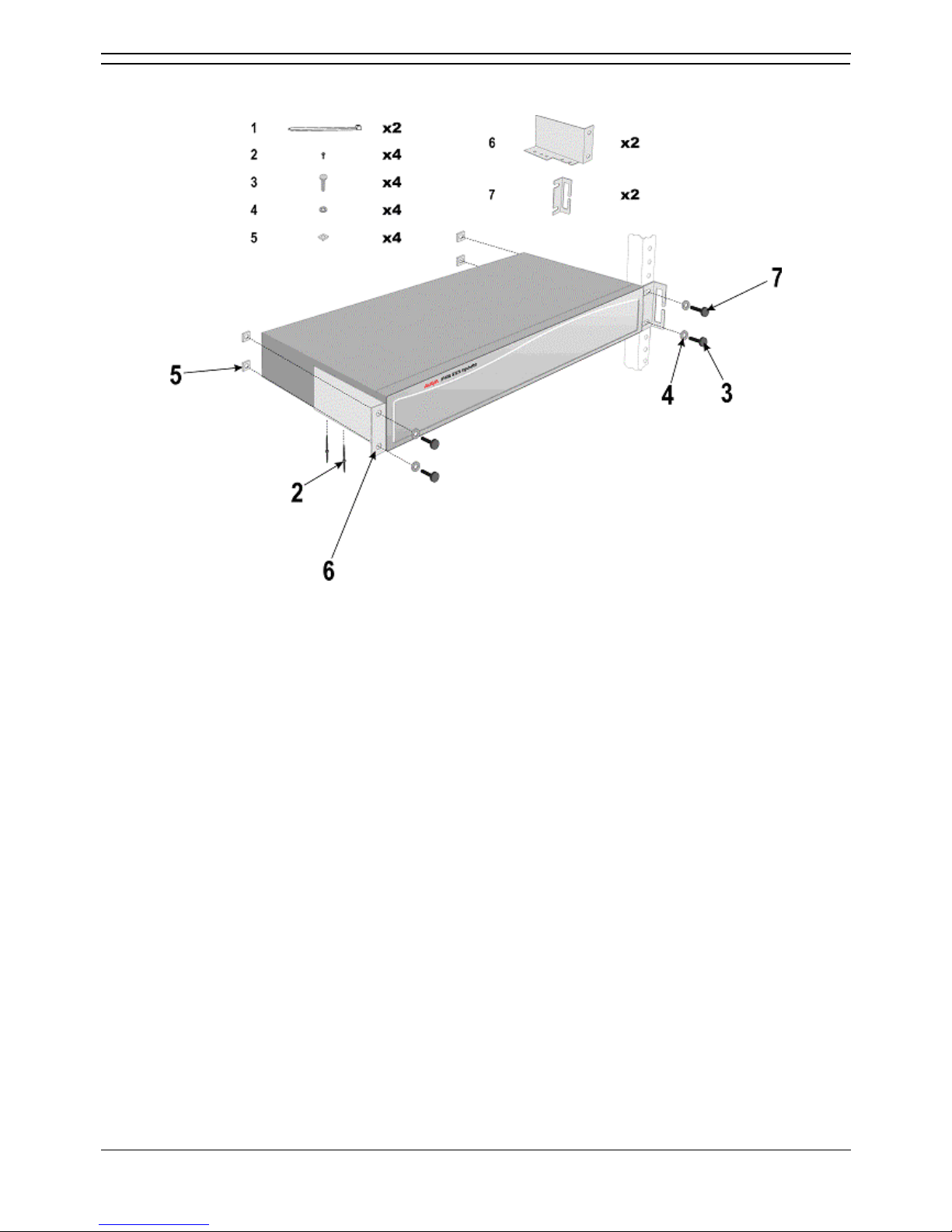
Installing a New System
Installation Manual Page 53
IP Office 2.1 40DHB0002USCL Issue 10c (11th May 2004)
Rack Mounting Assembly Instructions
IP403, 406, 412 and expansion modules can be mounted in any standard 19" rack as follows:
CAUTIONS
• Elevated Operating Ambient Temperature
If installed in a closed or multi-unit rack assemble, the operating ambient temperature of the rack
environment may be greater that the room ambient. Therefore, consideration should be given to
installing the equipment in an environment compatible with the manufacturer's maximum rated
ambient temperature (Tmra).
• Reduced Air Flow
Installation of the equipment in a rack should be such that the amount of air flow required for safe
operation of the equipment is not compromised.
• Mechanical Loading
Mounting of the equipment in the rack should be such that a hazardous condition is not achieved
due to uneven mechanical loading.
• Circuit Overloading
Consideration should be given to the connection of the equipment to the supply circuit and the
effect that overloading of circuits might have on overcurrent protection and supply wiring.
Appropriate consideration of equipment nameplate ratings should be used when addressing this
concern.
• Reliable Grounding
Reliable grounding of rack-mounted equipment should be maintained. Particular attention should
be given to supply connections other than direct connections to the branch circuit (e.g. use of
power strips).
Page 60
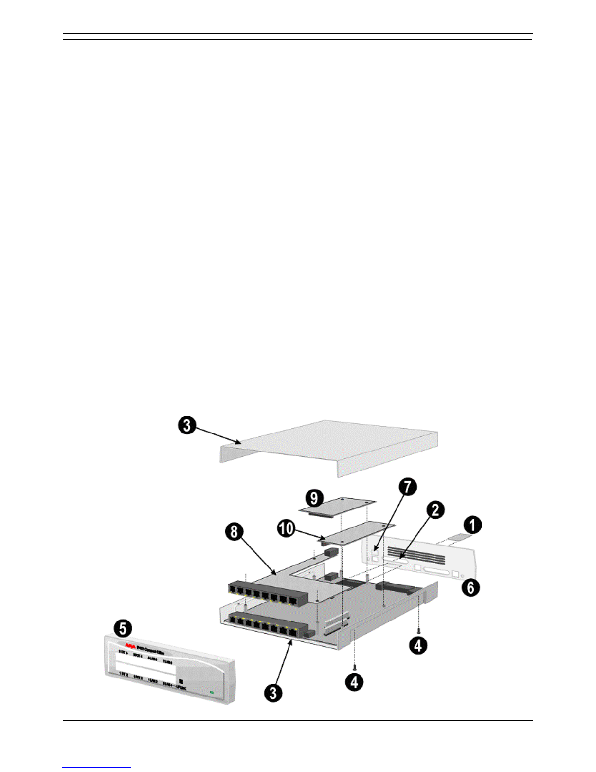
IP Office Installation
Installation Manual Page 54
IP Office 2.1 40DHB0002USCL Issue 10c (11th May 2004)
IP401 Expansion and Installation of Integral Modules
An IP401 Compact Office 2 can be expanded to an IP401 Compact Office 4.
Either unit can also be expanded with addition of a WAN card, a Voice Compression Module 5 (VCM5)
and/or a VME module (providing memory capacity for integral voice mail).
1. CAUTION - While installing modules, ensure that you wear aground wrist strap that is connected
to a suitable grounding point.
2. To add a VME memory card you do not need to de-assemble a module, simply insert the VME
memory card (item (1) ) into the slot in the rear panel below the WAN port position (item (2) ).
3. Remove the top cover (item (3)) from the base cover by removing the four retaining screws (two
either side - items (4)) and proceed as follows.
4. To expand an IP401 Compact Office 2 to an IP Compact Office 4:
• Remove and discard the front panel (item (5)).
• Remove the rear panel (item (6)). Only discard if a WAN module is being fitted (see
below).
• On the rear panel, press out the molding for the additional BRI RJ45 socket (item (7)).
• Plug the expansion board (item (8)) onto it's sockets and stand-off hex. pillars. Ensure
that the additional BRI RJ45 socket slots into the hole in the rear panel (item (7)). Secure
the expansion board (item (8)) with the three retaining screws.
• Mount the new front and existing rear panels if a WAN Module is not being fitted. If a
WAN module is being fitted, see below.
5. To add a WAN module:
• Remove and discard the rear panel (item (6)).
• Fit the new rear panel (with slot for WAN port 27-way D-type, items (6) and (2)).
• Mount WAN Module (item (9)) in position and secure with the two snap-in spacers.
6. To add a Voice Compression Module (VCM5):
• Mount the VCM Module (item (10)) in position.
• Secure with the two snap-in spacers.
Page 61
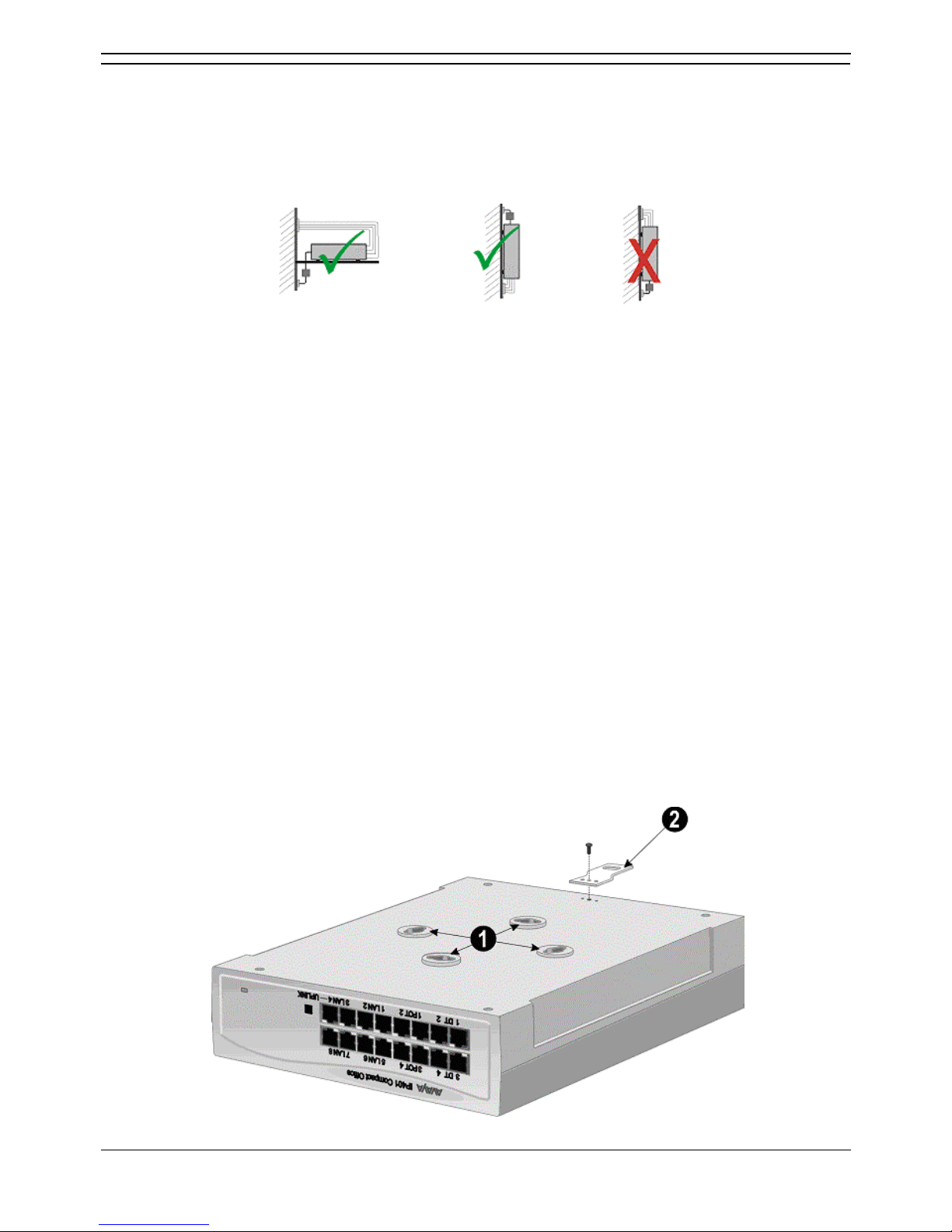
Installing a New System
Installation Manual Page 55
IP Office 2.1 40DHB0002USCL Issue 10c (11th May 2004)
IP401 Compact Office Wall Mounting
All variants of the IP401 Compact Office can be either shelf or wall mounted. Four retaining slots (item
(1) below) enable the IP401 Compact Office unit to be mounted and secured either:
• Horizontally on a shelf - leaving sufficient space for the cabling at both front and rear
of the unit.
• Vertically from a wall – with the front panel facing down only.
A Z-bracket (item (2) below, supplied with unit) is used to retain the Small unit in position.
Cautions:
1. The Z-bracket must not be used as the sole mounting fixture.
2. When mounting vertically, the weight of the IP401 Compact Office must be held by the two No 8
Panhead screws located into the retaining slots.
3. When mounted vertically, the air vents (on the rear panel of the IP401 Compact Office) must be
on the top surface. E.g. item (2) below must be fitted above the unit.
Procedure:
1. Drill two holes 16cm apart (horizontally or vertically – see Caution 3 above). Using suitable wall
fixings (wall plugs), insert two No.8, Panhead screws (25mm long min. - not supplied) into wall
leaving approximately 1cm proud of wall.
2. Fit the Z-bracket (item (2) below) onto the base of the unit using the M3 Plastite self tapping
screw supplied.
3. Slide the IP401 Compact Office unit onto the two screws, locating them into the two retaining
slots (item (1) below).
4. Mark the position of the retaining screw (No. 8 Panhead or similar – not supplied) that is to be
used through the slot of the Z-bracket .
5. Remove the unit from the wall and, using suitable wall fixings, drill a hole for the Z-bracket
retaining screw.
6. Re-position the IP401 Compact Office unit and secure with a No. 8 Panhead (or similar) through
the slot of the Z-bracket.
Page 62

IP Office Installation
Installation Manual Page 56
IP Office 2.1 40DHB0002USCL Issue 10c (11th May 2004)
Initial Assembly
Prior to initial assembly and mounting (rack or free standing) of your system, check that:
• For Analog Trunk 16 expansion modules, ensure that the protective ground is fitted.
• The required Trunk Interface Modules have been installed, are of the correct country variant type
and if functional grounding is required, that it has been fitted.
• Any optional Integral Voice Compression and/or Dual Modem Modules have been fitted.
• Where rack mounting is required, that the mounting brackets have been fitted.
• Where structured cabling is to be used it has been installed, conforms to all local regulations and
is clearly labeled.
Perform the following:
1. Mount the IP Office modules in their final location (free standing units are ideally stacked one
upon another).
2. Run the individual Lump-in-Line PSU cables back to the switchable mains supply but do not
switch-on or connect the PSUs to the IP Office modules.
3. With the exception of a WAN3 module, connect the IP Office Control Unit to the Expansion
Modules using Expansion Interconnect Cables (blue). These cables run from one of the
Expansion Ports on the rear of a base module to the Expansion Port on the rear of the Expansion
Modules. For WAN3 Modules, use a LAN Interconnect cable (403, 406) or LAN crossover cable
(412) running between one of the LAN Ports on the front of the control unit to the LAN Port on the
front of the WAN3 module.
4. Connect the Trunk Ports on the control unit, using PRI/BRI CAT5E cables, to your provider's
trunk sockets.
5. Connect the DT/DS/POT Ports on the front of the units, using DT Line Cords, to the structured
cable sockets. Note that in default, the lowest port number corresponds to the lowest extension
number (201).
6. Install all telephones in their appropriate locations.
7. Connect your PC LAN Port to one of the LAN Ports on the front of an IP Office base module
using a LAN Cable.
8. Connect the individual Lump-in-Line PSU to each IP Office module and switch on.
• IMPORTANT
Power on the Expansion Modules first. If the main IP Office Module does not detect an
item at power on, it will not use it. If power is switched on from a central point for all
modules, then, as the main unit is the slowest to start, this will be taken care of
automatically.
9. From the IP Office Administrator CD, install on your PC the software required to configure and
manage your Avaya IP Office.
10. Proceed to IP401 Expansion and Installation of Integral Modules
below.
Page 63

Installation Manual Page 57
IP Office 2.1 40DHB0002USCL Issue 10c (11th May 2004)
Basic System Programming
Introduction
This sections covers only the most basic aspects of system programming required to install an IP Office
system. When first powered up, all IP Office systems will operate as a simple PBX. However, full system
programming is highly dependent on customer requirements. Hence, some basic Initial Programming
must be performed before detailed configuration programming is possible. The Administration CD
(supplied with each system) contains the suite of programs required to install and maintain the IP Office
system. Once loaded, inter-active Help files provide all the instructions and details required to operate
and administer the program suite.
Notes:
1. When applying power to the IP Office system, the Expansion Modules must be switched on first.
If the main IP Office Module does not detect an item at power on it will never use it. If power is
switched on from a central point for all modules, then, as the main unit is the slowest to start, this
will be taken care of automatically.
2. When powered up correctly, all modules will display a steady green light in the center of each
module. When connection is established with ports, the port socket on the appropriate module
will show a green LED, e.g. the hub port connected to your PC for programming. IP Office
systems are ready for use within 1 minute of power on.
Page 64

IP Office Installation
Installation Manual Page 58
IP Office 2.1 40DHB0002USCL Issue 10c (11th May 2004)
Programming Tools
Programming Tools
The IP Office supports programming through any one of it's 10/100 Base-T hub port connections. The
tools required for programming of a newly installed IP Office system are:
• PC running Windows 95/98, NT, 2000, XP or ME (see Tools & Parts Required).
• PC with a LAN (NIC) card with either a fixed IP address (allocated by your system administrator)
or by using DHCP to obtain an IP address.
• IP Office Cat. 5E patch cable (red – supplied with system see PRI/BRI ISDN Cable).
• IP Office Administration CD (supplied with system).
• IP Office Manager Application Manual (supplied on CD with system).
• IP Office Feature Key (where software that requires a Licence Key is to be installed).
Note: Once installed, the software level of all software fitted to the IP Office system can be identified.
With Manager running, use File/Advanced/Upgrade to display menu. Refer to the Manager Application
Manual for details of system configuration, software upgrade, etc.
PC to IP Office LAN Port Connection
An IP Office system, when first powered up, will scan the LAN for a DHCP server that will allocate it with
an IP address. If the IP Office system does not find a DHCP server then it will automatically become a
DHCP server itself with an IP address of 192.168.42.1. The IP Office system will allocate an IP address
to the PC if required. Initially, the IP Office system assumes that all addresses are on the local LAN and
that the PC software supplied uses broadcast to establish communication with the IP Office system.
The IP Office hub port can be connected in two ways; either directly to a PC or as part of a LAN. Both
methods use an IP Office Cat. 5E patch cable (see PRI/BRI ISDN Cable
) connected between one of the
LAN hub ports on the front of the IP Office base unit and the PC.
• Direct Connection
This method is used for local system programming directly from a PC.
• LAN Network Connection
This is the option to use for remote programming access. It will require liaison with the LAN
network manager to obtain the IP address details and to ensure that the IP traffic routing is
allowed. When connected to an IP LAN network, you must consult with the Network Manager to
obtain the required IP settings. For IP operation the IP Office requires a static IP address
including a subnet mask and default gateway value.
Page 65
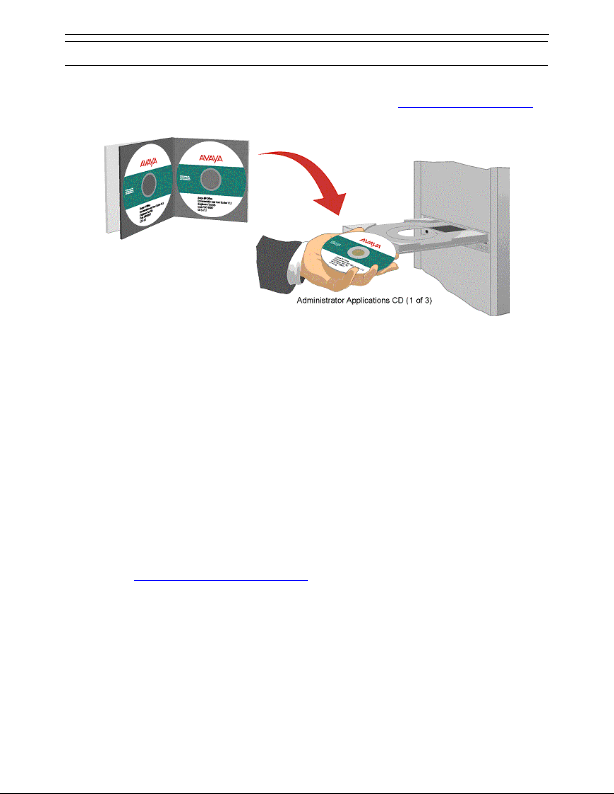
Basic System Programming
Installation Manual Page 59
IP Office 2.1 40DHB0002USCL Issue 10c (11th May 2004)
Initial Programming
Initial Programming
All the software used to configure and manage the IP Office system must be installed on your PC from
the supplied Administrator CD. With the initial assembly completed (see Rack Mounting Barrier Boxes
)
and your PC connected to the IP Office system, insert and run the Administrator (CD 1 of 3) to install
Software Level 2.0+ on your PC.
1. The CD Autoruns. You are initially presented with the option to select which language you wish to
use. Select the language from the pull down list and click OK.
2. If not already installed on your PC, you are then given the option to install the Microsoft Net 1.1
Framework application. This should be installed if you wish to use the IP Office Installation
Wizard application. If you are going to install this application, then click OK, agree to the License
and on completion click OK. The Welcome screen is then displayed; click Next to continue.
3. The Destination folder location option menu is displayed. Either accept the default location (click
on Next) of where the Administration Suite is to be installed or change the location by clicking on
Browse and entering a new location
4. Select which components you wish to install by selecting the appropriate boxes (Manager and
Voice Mail are default minimums) and click Next.
5. Name the program folder or accept the default (IP Office), click Next and wait for the
Administration Suite installation to be completed.
6. Installation runs and on completion select Restart now and click Finish twice.
7. The IP Office Administration suite of applications is now installed on your PC and you are now
ready to configure your Avaya IP Office.
8. You have two choices:
• Using the IP Office Installation Wizard
• Using the IP Office Manager Application
Page 66

IP Office Installation
Installation Manual Page 60
IP Office 2.1 40DHB0002USCL Issue 10c (11th May 2004)
Using the IP Office Installation Wizard:
This application is recommended for first time installers. From the Program file on your PC, select IP
Office and Wizard. The application is intuitive and will guide you through the configuration process.
Follow the instructions on each menu and use the Help files for detailed instructions.
Using the IP Office Manager Application:
This application is recommended for experienced installers. From the Program file on your PC, select IP
Office and Manager.
1. You will be requested to enter both the Operator Name and Password. This password gains
access to the Configuration Tree facilities allocated to the named operator. At default, five options
are available, for full access, select Administrator: Name Password For full facilities
access: Administrator Administrator
2. The Configuration Tree blank screen is displayed. To display the facilities available for this
named operator's Configuration Tree, from File select Open and, when requested, enter the
password for the IP Office unit. The default for the IP Office unit is password.
3. You must change the Operator Name, it's Passwords and the Password for the IP Office
unit as soon as possible. A combination of at least 8 alpha and numeric characters is
recommended for passwords, avoiding the use of common words.
4. From the Configuration Tree, select File and Change Password. The operator Name is
displayed, together with both the Password and Confirm Password as a series of xxxxx's. Enter
the new Password and Confirm Password. Click OK and Save As.
5. From the Configuration Tree for the Administrator, double click on the System icon to display the
System Configuration menu for the IP Office unit. The following items must be set/changed:
• Name
A name to identify this system. Used to identify the configuration by its location or
customer's company name.
• Locale
This option sets country variations, e.g. US = enu, UK = eng, Netherlands = nld, Germany
= deu. Locale defines the country dependent default ring sequences, display
types/language, etc. This option is automatically set dependent on the Regional Settings
of the PC on which the Manager is running. For instance, if this setting defaults to eng
rather than enu this is because the Regional Settings of the PC are set to English (United
Kingdom) therefore change the Regional Settings to English (United States).
• Password
This is the password (default password) for controlling access to the IP Office unit and is
required to upgrade, reboot and send or receive configurations from the unit. Change this
password as soon as possible.
6. Basic programming is completed and you can now configure the system to the customer's
requirements. Full details on configuration and administration are contained in the inter-active
Help files and/or the Manager Application Manual. Press F1 to access the Help files.
• Note: To activate Voicemail Lite, from the Program file, select IP Office and Voicemail and click
on Run.
Page 67

Basic System Programming
Installation Manual Page 61
IP Office 2.1 40DHB0002USCL Issue 10c (11th May 2004)
Software Upgrades
Software Upgrades
The software level of the IP Office Administration suite and the core software within the IP Office
hardware should always be the same. Installing a new version of IP Office Manager includes core
software files appropriate for upgrading the hardware.
• Validated Upgrades
IP Office 2.1 software supports validated upgrades. This allows remote upgrades to be
attempted. However validated upgrades are only supported for units with core software level 2.1
or higher already installed.
For hardware with Level 2.0 or earlier software installed, validated upgrades are not supported.
Therefore, when upgrading a system to Level 2.1, the upgrade must be done from a PC running
IP Office Manager that:
• Has a fixed IP address.
• Is connected on the same LAN segment as the IP Office control units.
• Pre 2.0 IP403 Systems
These systems must follow a two-stage upgrade process. See Upgrading an IP403 to Software
Level 2.1.
Removing the Existing IP Office Admin Suite
During this process, existing received configuration files are not affected.
From Start select Settings | Control Panel | Add/Remove Programs. Highlight IP Office Admin
Suite and click Change/Remove.
The Install Shield Wizard is run.
Select Modify and click Next>.
Make a note of the ticked options. These indicate the components of the IP Office Administration
suite current installed on the PC. Click < Back.
Select Remove and click Next. Confirm that you wish to remove all components.
If Read Only files are detected, click OK. If Locked Files are detected, click Ignore. Note: Your
configuration and license files will be untouched and available for the upgraded software.
Depending on the components removed you may be provided with the option to reboot your PC.
Select Reboot.
Click Finish.
You can now proceed with installing the new IP Office Admin suite, following the reboot if required.
Page 68

IP Office Installation
Installation Manual Page 62
IP Office 2.1 40DHB0002USCL Issue 10c (11th May 2004)
Installing the New IP Office Admin Suite
This process should only be followed after having removed the previous IP Office Administration suite
components as detailed above.
1. Insert the IP Office Admin CD.
2. The CD should auto run and display a language selection menu. Select the required installation
language and click OK.
3. The InstallShield Wizard will load and prepare for installation.
4. A Welcome screen is display. Click Next >.
5. A menu for selecting the installation destination is displayed. Leave this set at the default unless
you have specific reasons for doing otherwise. Click Next >.
6. A menu appears for selecting which components of the IP Office Administration Suite you want to
install. Tick the list to match the previously removed suite. Click Next >.
7. A menu for selecting the Program Folder appears. Leave this set at the default unless you have
specific reasons for doing otherwise. Click Next >.
8. Depending on the components installed, a menu asking you to reboot the PC may be displayed.
Select to restart the PC.
9. Click on Finish.
Upgrading the Unit Software
Installing IP Office Manager also includes appropriate .bin software files for the hardware units within the
IP Office system.
• WARNING: IP Office 2.0 or Earlier Systems
For systems currently at 2.0 or earlier software, this process must be done from a PC with fixed
IP address and on the same LAN segment as the IP Office. It must not be attempted via RAS or
routed network links.
• WARNING: IP403 Systems
For IP Office 403 systems with Level 1.4 or earlier software the upgrade process is a multistage
operation. See Upgrading an IP403 to Software Level 2.0
.
1. Select Programs | IP Office | Manager.
2. You will be requested to enter an Operator Name and Password for Manager. The default name
and password are Administrator and Administrator.
3. IMPORTANT: Use
to load the configuration from the IP Office system. Taking this step
creates a BOOTP entry in Manager for the system. It also ensures that you have a copy of the
configuration and the correct system password.
4. Select File | Advanced | Upgrade.
5. The IP Office Upgrade Wizard is started and will scan for IP Office units. For the units found it will
show the unit type, its currently installed version of software and the what version of software is
available from Manager. Units for which a later version of software is available will be already
ticked.
6. If any of the units have pre-version 2.1 software, untick Validate. The validated upgrade option is
only supported for units which already have 2.1 or higher software installed.
7. Check that the list of ticked units is as you require.
8. Click Upgrade.
9. Enter the system passwords when requested.
10. Progress of the upgrade process is shown.
Page 69

Basic System Programming
Installation Manual Page 63
IP Office 2.1 40DHB0002USCL Issue 10c (11th May 2004)
Upgrading an IP403 to Software Level 2.1
IP403 systems with Level 1.4 or earlier core software cannot be directly upgraded to Level 2.1 core
software. They must be upgraded as follows:
1. Upgrade to Level 1.99 using the ip403.bin file found in the Manager application's IP403V1_99
folder.
2. Upgrade from Level 1.99 to Level 2.1 using the ip403.bin file found in the Manager application's
IP403V2_1 folder.
Within the IP Office Upgrade Wizard, to switch between the core software .bin files in different folders,
use the following:
1. Right-click on the Upgrade Wizard screen.
2. Select Select Directory and browse to the folder containing the required core software .bin file.
3. Click OK.
4. The details in the Available software column should change.
Page 70

Page 71

Installation Manual Page 65
IP Office 2.1 40DHB0002USCL Issue 10c (11th May 2004)
Telephone Installation
Checking Telephones
Checking Telephones
It is preferable to leave connection of telephones until after installation of other IP Office equipment and
full system programming has been completed (including the set-up of directory numbers and names).
Note that by IP Office telephones we mean devices manufactured and supplied as part of the IP Office
product range and not third party telephone devices.
While installing and checking each telephone, it may also be required to do some basic telephone
programming such as setting-up call forwarding, call pickup, group numbers, etc.
The detailed instructions for setting-up these feature are contained in the Manager Application Manual
and within the Configuration Tree Help files. With the configuration tree for Administrator open, press F1
to access the Help files.
The following instructions are the minimum required for testing and wall mounting of IP Office
telephones. Detailed instructions for testing, wall mounting and using IP Office telephones are contained
in the appropriate Installation and User Guides contained on the CD supplied with each system.
More
• Connecting & Testing IP Office Telephones
• Connecting & Checking Two-Wire Telephones
• Power Fail Telephones and Sockets
Connecting & Testing IP Office Telephones
Use the following process to connect and check IP Office telephones.
To check a IP Office telephone
:
1. Unpack the telephone and check that all parts are present including labels and user guides.
2. Insert the handset cord into the base. Route the cord thorough the cable channels to come out at
the side of the telephone.
3. Insert the line cord into the wall socket.
4. Insert the line cord into the telephone's base and route the cord thorough the cable channels to
come out at the side/rear of the telephone.
5. Lift the handset, check that you hear dial tone and make a test call to another extension.
6. On a display telephone, ensure that the display shows the number called and that the display is
in the correct language.
• Note
On 44/4600 series telephones, the line cord is fitted with an RJ11 plug. In which case,
when connecting directly to an IP Office module, an RJ11/RJ45 adapter should be used.
Similarly, the structured wiring should terminate in RJ11 sockets.
Page 72

IP Office Installation
Installation Manual Page 66
IP Office 2.1 40DHB0002USCL Issue 10c (11th May 2004)
Connecting & Checking Two-Wire Telephones
All two-wire devices (POTS) should be tested according to the manufacturer's instructions before
connection to the IP Office system. Connect the two-wire device and make a test call.
Power Fail Telephones and Sockets
All power fail sockets (on IP400 Analog Trunk 16 modules only – see IP400 Analog Trunk 16) must be
tested.
To test a power fail socket
:
1. Locate the socket and check that it is clearly labeled as a power fail socket.
2. Connect a telephone to the socket.
3. With power to the IP Office system switched on, make a test call.
4. Switch the power to the IP Office system off and again make a test call.
5. Switch the power to the IP Office system back on again.
6. Repeat the test for any other power fail sockets.
• Note
Where E911 statuary requirements for discrete location identification of a power fail
phone are required on the transmitted CLI, ensure that the relevant installation
programming is completed.
Page 73
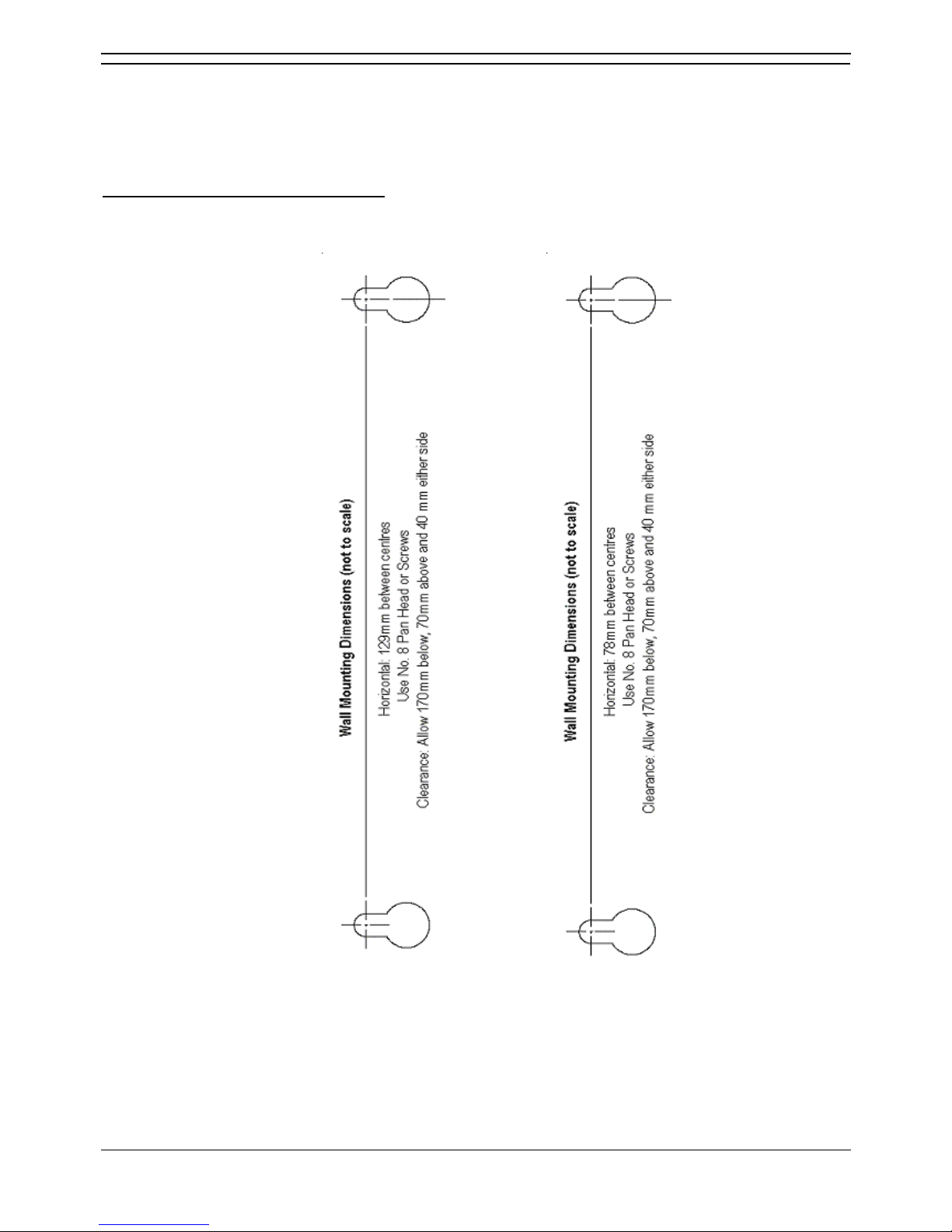
Telephone Installation
Installation Manual Page 67
IP Office 2.1 40DHB0002USCL Issue 10c (11th May 2004)
Wall Mounting 2000 Series Telephones
Mounting brackets exist which clip onto the base on IP Office telephones. These brackets (two required
per telephone) can be used to either raise the desk position of the telephone or for wall mounting. Before
wall mounting a telephone, check that the surface is flat, vertical and not subject to movement or
vibration.
To wall mount an IP Office telephone
:
1. Using the dimensions given below, mark the position for the screw holes. Ensure that adequate
clearance above and below the telephone is allowed.
Additional Items :
– Two No. 8 Pan
head or Round
head screws. –
Two wall plugs. –
Drill and drill bit. –
Screwdriver.
2. Drill the necessary holes and insert the wall plugs.
3. Insert the screws, leaving the heads approximately 3mm proud of the surface (check by clipping
a bracket over the screw head).
4. Attach the brackets to the telephone. Then slide the bracket key-slots over the screw-heads.
5. Reverse the position of the handset retainer tab (located below the hook switch on the
telephone). This keeps the handset in place whilst the telephone is mounted on the wall.
Page 74
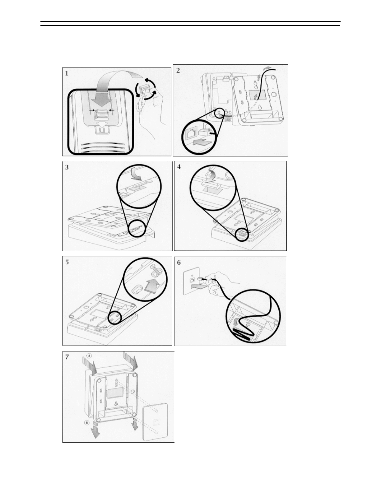
IP Office Installation
Installation Manual Page 68
IP Office 2.1 40DHB0002USCL Issue 10c (11th May 2004)
Wall Mounting 44/4600, 2420 & 6400 Series Telephones
The following pictorial instructions, although for a 4600 telephone, provide a general overview on how to
wall mount both series of telephones. For safety instructions and details, refer to the specific instructions
for each telephone type (supplied on the CD with the IP Office system).
Page 75

Installation Manual Page 69
IP Office 2.1 40DHB0002USCL Issue 10c (11th May 2004)
System Handover
Checklist
Equipment :
• Have all extensions been tested?
• Have all exchange lines been tested?
• Have all private wires been tested?
• Is system programming in line with the customer specification? E.g. all specified applications, CTI
settings, etc.
• Has the customer been made aware of the drop back (power fail) locations? Are these been
clearly marked and have they been tested?
• Has the mains supply (and any UPS if fitted) been tested?
• Where VoIP is to be deployed have the appropriate network design criteria and QoS mechanisms
been applied as per the Avaya planning guidelines.
Wiring
:
• Have the trunk modules and Analog Trunk 16, where equipped, been fitted with the appropriate
functional/protective grounds (see Grounding
).
• Is the distribution wiring (structured cabling) satisfactory to the required national standards?
• Are all wires and cables clearly labeled.
• Is the site clean and tidy with all rubbish removed?
Information
:
• Have the telephone user guides been issued to the user.
• Has the customer been made aware of the telephone number for maintenance/fault reports.
Feature Key
:
• Where a Feature Key has been used (for software requiring a license), record it's physical
location (location of the PC is it plugged into) and leave a record of such on site with the system.
Page 76

Page 77

Installation Manual Page 71
IP Office 2.1 40DHB0002USCL Issue 10c (11th May 2004)
Safety and Homologation Statements
Safety and Homologation Statements
CE Mark
The "CE" mark affixed to this equipment means that the unit complies with the 1999/5/EC (R&TTE),
89/336/EEC (EMC) and 72/23EEC (LVD) Directives
Declaration of Conformity
The Declaration of Conformity (DoC) for the IP400 Office products is contained with in the CD
accompanying the products.
This warning symbol is found on the base of IP401, IP403, IP416 and IP412 units and on the base of the
IP400 Digital Station 80W Lump-in-Line PSU (see IP400 Digital Stations 16/30
). Refer to Trunk Interface
Modules for information concerning which Trunk Interface module variants are fitted in which country.
• WARNING
The Avaya IP400 Office units are intended to be installed by 'Service Personnel' and it is
the responsibility of the Service Personnel to ensure that all subsidiary interconnected
equipment is wired correctly and also meet the safety requirements of IEC60950 or
UL60950 where applicable.
Lithium Batteries
A lithium battery is fitted to the real time clock on the IP401/403/406 and IP412 mother boards.
• WARNING
The Lithium battery must only be replaced by Avaya personnel or authorized
representatives. There is a danger of explosion if the battery is incorrectly replaced.
Replace only with the same or equivalent type recommended by the manufacturer.
Dispose of used batteries according to the manufacturer's instructions.
Lightning Protection/Hazard Symbols
Lightning protectors
The buildings lightning protectors must be verified as follow:
1. Check the lightning protectors, at the trunk cable entry point to the building housing the Avaya IP
Office, paying special attention to the lightning protection grounding. Report any problems, in
writing, to the telephone company.
2. Equipment that is designed to be connected using internal wiring is typically not lightning
protected. Hence, Avaya IP Office extension cabling must not leave the building. For
installations where telephones and/or other standard (tip/ring) devices are installed in another
building then lightning protection is required (see Out of Building Telephone Installations
).
Hazard Symbol
The shock hazard symbol is intended to alert personnel to electrical hazard or equipment damage. The
following precautions must also be observed when installing telephone equipment:
1. Never install telephone wiring during a lightning storm.
2. Never install telephone jacks in wet locations unless the jack is specifically designed for wet
locations.
3. Never Touch uninsulated telephone wires or terminals unless the telephone line has been
disconnected at the network interface.
4. Always use caution when working with telephone lines.
Page 78

IP Office Installation
Installation Manual Page 72
IP Office 2.1 40DHB0002USCL Issue 10c (11th May 2004)
Electromagnetic Interference Information
Federal Communications Commission (FCC)
This equipment has been tested and found to comply with the limits for a Class A digital device, pursuant
to Part 15 of the FCC Rules. These limits are designed to provide reasonable protection against harmful
interference when the equipment is operated in a commercial environment. This equipment generates,
uses, and can radiate radio frequency energy and, if not installed and used in accordance with the
instruction manual, may cause harmful interference to radio communications. Operation of this
equipment in a residential area is likely to cause harmful interference, in which case the user will be
required to correct the interference at his or her own expense.
Canadian Department of Communications (DOC)
''NOTICE: This equipment meets the applicable Industry Canada Terminal Equipment Technical
Specifications. This is confirmed by the registration number. The abbreviation, IC, before the registration
number signifies that registration was performed based on a Declaration of Conformity indicating that
Industry Canada technical specifications were met. It does not imply that Industry Canada approved the
equipment."
Page 79
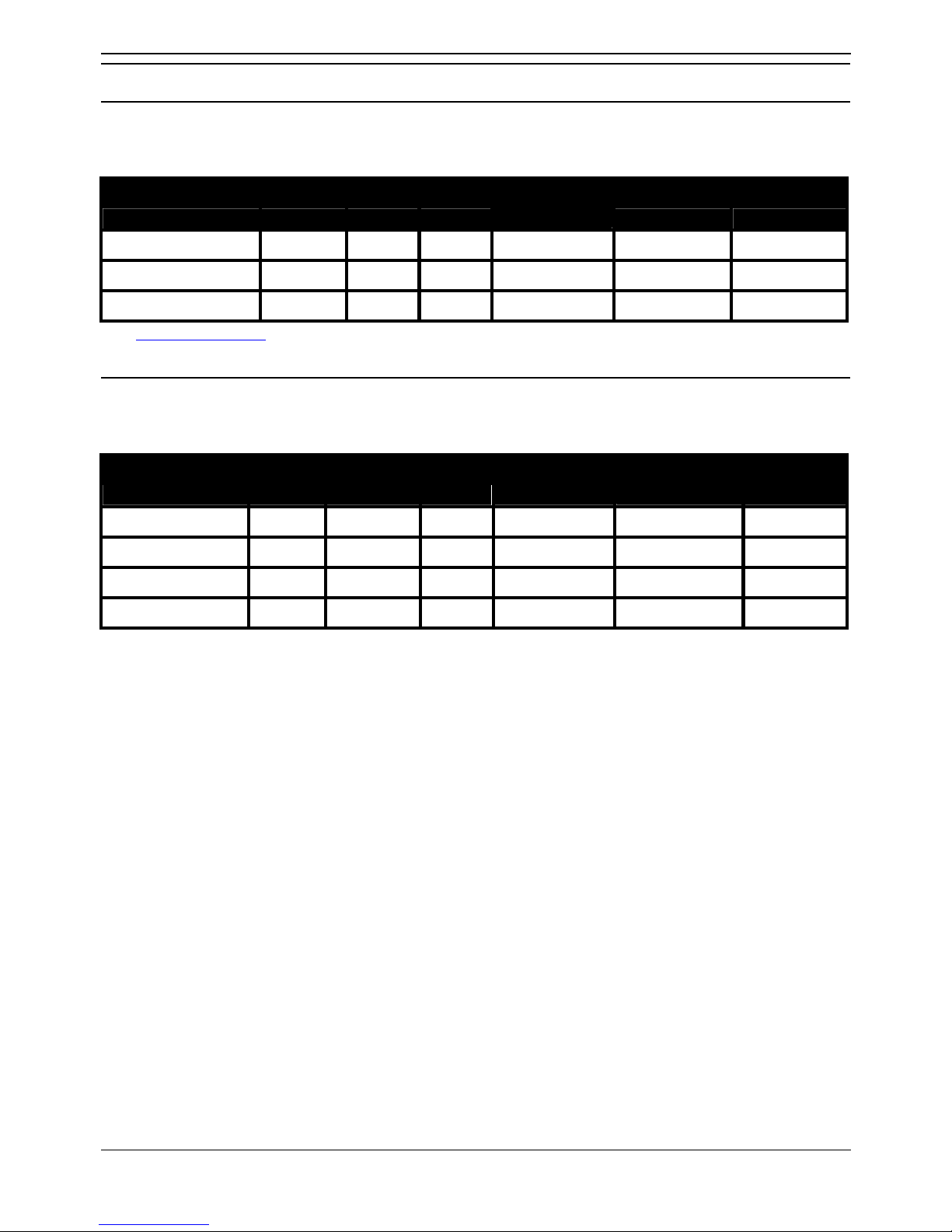
Safety and Homologation Statements
Installation Manual Page 73
IP Office 2.1 40DHB0002USCL Issue 10c (11th May 2004)
Trunk Interface Modules
USA/Canada
To ensure the validation of the approvals in US and Canada, only the following interface cards must be
installed in the following IP400 Office products:
Product Quad BRI PRI-E1 PRI-T1 Analog Trunk 4
(LS)
Dual PRI-E1 Dual PRI-T1
IP403 Office DS No No Yes Yes No Yes
IP406 Office No No Yes Yes No Yes
IP412 Office* No No Yes Yes No Yes
See Trunk Module Kits for country specific variant SAP codes.
Rest Of World (ROW)
To ensure the validation of the approvals in ROW (i.e. EU, Hungary, Australia and New Zealand), only
the following interface cards must be installed as detailed in the following IP400 Office products:
Product Quad BRI PRI-E1 PRI
E1-R2*
PRI-T1 Analog Trunk 4
(LS)
Dual PRI-E1
Dual PRI-E1-R2*
Dual PRI-T1
IP403 Office DT Yes Yes No Yes No No
IP403 Office DS Yes Yes No Yes No No
IP406 Office Yes Yes No Yes No No
IP412 Office Yes Yes No Yes Yes No
* CALA /Korea only.
Page 80

IP Office Installation
Installation Manual Page 74
IP Office 2.1 40DHB0002USCL Issue 10c (11th May 2004)
Further Information and Product Updates
Further Information and Product Updates
Further information, including Product and Reference Manual updates, can be obtained from Avaya's
Dealers and Distributors, or from Avaya's web site: http://www.avaya.com.
This guide is also available from the Avaya's support web site: http://support.avaya.com
Support Telephone Numbers
For initial help and support, contact your distributor/supplier. The following contact points are for Avaya
authorized partners.
In the USA only, Avaya provides a toll-tree Customer Helpline 24 hours a day:
• Name: Avaya Technical Support Organization (TSO)
• Customer Helpline: 1 800 628-2888
• Address: 8744 Lucent Blvd., Highlands Ranch, Colorado, 80129 USA
• URL: http://support.avaya.com/
If you need assistance when installing, programming, or using your system, call the Helpline or your
Avaya representative. Consultation charges may apply.
Outside the USA, if you need assistance when installing, programming, or using your system, contact
your Avaya representative.
• URL: http://support.avaya.com
Page 81

Safety and Homologation Statements
Installation Manual Page 75
IP Office 2.1 40DHB0002USCL Issue 10c (11th May 2004)
Regulatory Instructions for Use
Regulatory Instructions for Use
Any changes or modifications not expressly approved by Avaya ECS Ltd could void the user's authority
to operate the equipment.
• IP Office Operation in Australia
• IP Office Operation in Canada
• IP Office Operation in EU
• IP Office Operation in New Zealand
• IP Office Operation in USA
IP Office Operation in Australia
Connection
Connection of IP400 Office products must be via a Line Isolation Unit with a telecommunications
compliance label.
BRI Interface
During the configuration, ensure "000" emergency number is not barred, by performing the following:
• Short Code: "000" Telephone No.: "000;" Function: "Dial Emergency"
Connections to TS013, the following Bearer Capabilities shall not be used:
• 7kHz Audio Video Restricted Digital Information
If unknown type of number is used in calling party number, the network will use the default CLI.
The system must be configured for Point to Multi point connection to comply with Austel requirements for
connecting to TS013 circuits.
As the IP Office does not support emergency dialing after loss of power, the following warning notice
should be recognized:
• WARNING
This equipment will be inoperable when mains power fails.
PRI Interface
During the configuration, ensure "000" emergency number is not barred, by performing the following:
• Short Code: "000" Telephone No.: "000;" Function: "Dial Emergency"
WARNING
This equipment will be inoperable during mains power failure.
Page 82

IP Office Installation
Installation Manual Page 76
IP Office 2.1 40DHB0002USCL Issue 10c (11th May 2004)
Industry Canada Notification (DoC)
This equipment meets the applicable Industry Canada Terminal Equipment Technical Specifications.
This is confirmed by the registration number. The abbreviation, IC, before the registration number
signifies that registration was performed based on a Declaration of Conformity indicating that Industry
Canada technical specifications were met.
It does not imply that Industry Canada approved the equipment.
''NOTICE: The Ringer Equivalence Number (REN) for this terminal equipment is 1. The REN assigned to
each terminal equipment provides an indication of the maximum number of terminals allowed to be
connected to a telephone interface. The termination on an interface may consist of any combination of
devices subject only to the requirement that the sum of the Ringer Equivalence Numbers of all the
devices does not exceed five.''
IP Office Operation in EU
1. 999 and 112 calls must not be barred. Doing so will invalidate the approval.
2. All connections at the MDF shall be identifiable by suitable labeling.
3. The CE mark displayed on IP Office equipment indicates the systems compliance with the EMC,
LVD, and R&TTE Directives and common technical regulations for Primary Rate and Basic Rate
ISDN.
4. All ports for the connection of other non-telecommunications apparatus have a Safety Extra Low
Voltage (SELV) safety status.
IP Office Operation in New Zealand
The grant of a Telepermit for any item of terminal equipment indicates only that Telecom has accepted
that the item complies with minimum conditions for connection to its network. It indicates no
endorsement of the product by Telecom, nor does it provide any sort of warranty. Above all, it provides
no assurance that any item will work correctly in all respects with another item of Telepermitted
equipment of a different make or model, nor does it imply that any product is compatible with all of
Telecom's network services.
Page 83

Safety and Homologation Statements
Installation Manual Page 77
IP Office 2.1 40DHB0002USCL Issue 10c (11th May 2004)
IP Office Operation in USA
FCC Notification
This equipment is registered with the ACTA (Administrative Council for Terminal Attachments) in
accordance with FCC Part 68 of its rules. In compliance with those rules, you are advised of the
following:
• Means of Connection
Connection of this equipment to the telephone network shall be through a standard network
interface jack. Connection to 1.544-MBps digital facilities must be through a USOC RJ48C.
Connection to the Analog Trunk facilities must be through a USOC RJ45S.
• Notification to the Telephone Companies
Before connecting this equipment, you or your equipment supplier must notify your local
telephone company's business office of the telephone number or numbers you will be using with
this equipment.
• The facility interface codes (FIC) for 1.544-MBps digital connection (i.e. IP400 Office PRI-T1)
are 04DU9.BN, 04DU9.DN, 04DU9.IKN, 04DU9.ISN.
• The facility interface code (FIC) for analog trunk connection (i.e IP400 Office Quad Analog
Trunk-LS) are OL13A, OL13B, OL13C, 02AC2, 02LA2, 02LB2, 02LC2, 02LR2, 02LS2.
• The facility interface code (FIC) for analog trunk connection (i.e. IP400 Office ATM16-LS/GS)
are OL13A, OL13B, OL13C, 02AC2, 02GS2, 02LA2, 02LB2, 02LC2, 02LR2, 02LF2.
• The Service Order Code (SOC) for 1.544-MBps digital connection (i.e. IP400 Office PRI-T1) is
6.0Y.
• The Service Order Code (SOC) for analog trunk connection (i.e. IP400 Office Quad Analog
Trunk-LS) is 9.0Y.
• Disconnection
You must also notify your local telephone company if and when this equipment is permanently
disconnected from the line or lines.
• Hearing Aid Compatibility
The custom telephone sets for this system are compatible with inductively coupled hearing aids
as prescribed by the FCC.
Ringer Equivalence Number (REN). The REN is used to determine the number of devices that may be
connected to the telephone line. Excessive RENs on the line may result in the devices not ringing in
response to an incoming call. In most, but not all, areas, the sum of the RENs should not exceed five. To
be certain of the number of devices that may be connected to the line, as determined by the total RENs,
contact the local telephone company to determine the maximum REN for the calling area.
Page 84

Page 85
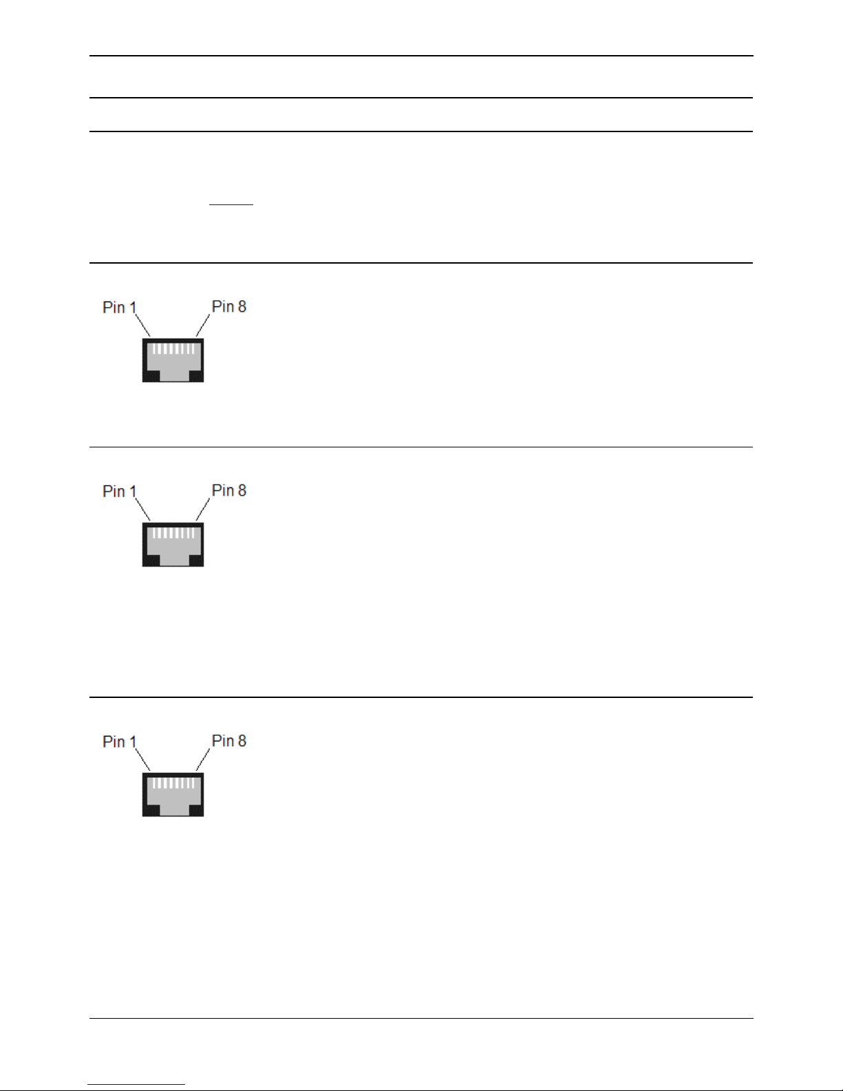
Installation Manual Page 79
IP Office 2.1 40DHB0002USCL Issue 10c (11th May 2004)
Technical Data
Port Pinouts
Port Pinouts
This section provides the technical specifications for the IP Office ports with the exception of the USB
port and cable. All diagrams are viewed from the front. The USB port and cable (up to 5 meters) are
standard. Refer to Cables
for cable details.
• Note: Throughout the following, Tx = from IP Office and Rx = to IP Office.
Analog Trunk Ports (RJ45)
Pin No. Description
1-3 Do not use.
4 Ring.
5 Tip.
6-8 Do not use.
Power Fail and POT Ports (RJ45)
Pin No. Description
1 & 3
Do not use.
2
Connected to Pin 6*.
4
Ring.
5
Tip.
6
Connected to Pin 2*.
7-8
Do not use.
* Pins 2 and 6 are shorted together and, via a 'ringer' capacitor, connected to in 5.
DS/DT Ports (RJ45)
Pin No. Description
1-3 Do not use.
4 Sig 1.
5 Sig 2.
6-8 Do not use.
Page 86
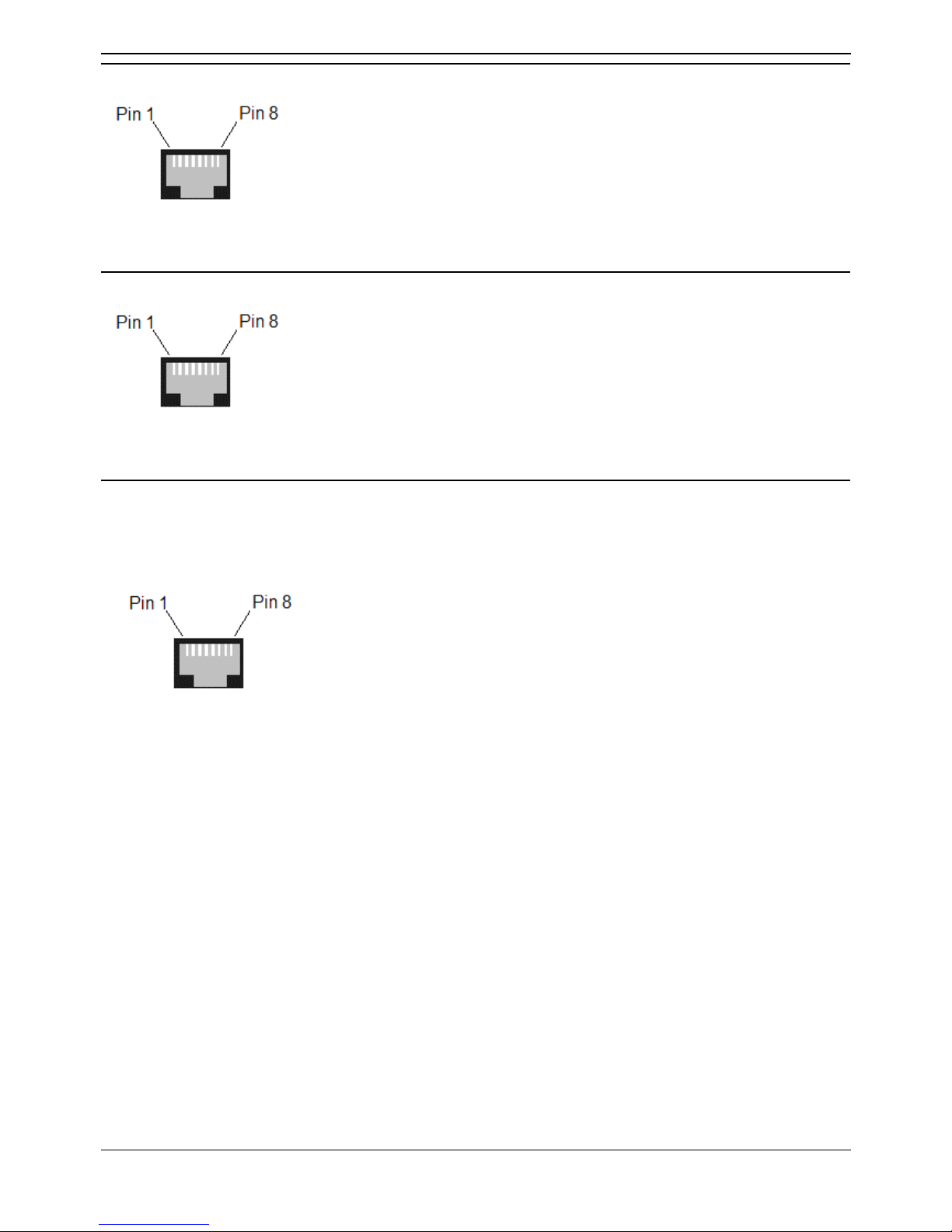
IP Office Installation
Installation Manual Page 80
IP Office 2.1 40DHB0002USCL Issue 10c (11th May 2004)
ISDN Port – BRI (RJ45)
Pin No. Description Signal Direction
3 Transmit Data (Tx-A) >
4 Receive Data (Rx-A) <
5 Receive Data (Rx-B) <
6 Transmit Data (Tx-B) >
ISDN Port – PRI (RJ45)
Pin No. Description Signal Direction
1 Receive Data (Rx-A) <
2 Receive Data (Rx-B) >
4 Transmit Data (Tx-A) >
5 Transmit Data (Tx-B) <
LAN Port – 10/100 BaseT
For IP Office 403/406 the information below refers to LAN ports 1 – 7. Port 8 is switchable (exchanges
Tx and Rx signals).
For IP412 and WAN3, both ports have the Rx and Tx connections exchanged.
Pin No. Description Signal Direction
1 Receive Data (Rx-A) <
2 Receive Data (Rx-B) >
3 Transmit Data (Tx-A) >
6 Transmit Data (Tx-B) <
Page 87
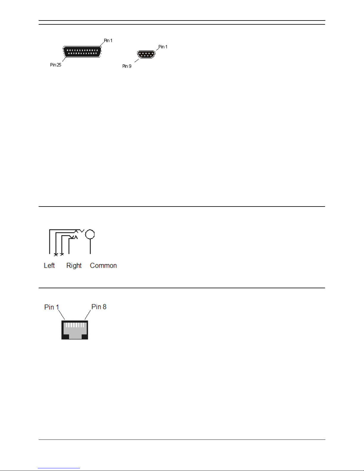
Technical Data
Installation Manual Page 81
IP Office 2.1 40DHB0002USCL Issue 10c (11th May 2004)
DTE Port (25 Way or 9 Way D-Type socket)
Pin No
(25 Way).
Pin No
(9 Way).
Description Signal Direction
2 3 Receive Data (Rx) <
3 2 Transmit Data (Tx) >
4 7 Request to Send (RTS) <
5 8 Clear to Send (CTS) >
6 6 Data Set Ready (DSR) >
7 5 Signal Ground
8 1 Data Carrier Detect (DCD) >
20 4 Data Terminal Ready (DTR) <
22 9 Ring Indicator (RI) >
Audio Port (3.5mm Stereo Jack Socket)
Pin No. Description Signal Direction
Common Common
Left Audio in – Left Channel <
Right Audio in – Right Channel <
Expansion Port (RJ45 Socket)
Pin No. Description Signal Direction
1 Receive Data (Rx-B) <
2 Receive Data (Rx-A) <
3 Sync-B >
4 Clock (Clk-B) >
5 Clock (Clk-A) >
6 Sync-A >
7 Transmit Data (Tx-B) >
8 Transmit Data (Tx-A) >
Shield Connected to chassis. Ground.
Page 88

IP Office Installation
Installation Manual Page 82
IP Office 2.1 40DHB0002USCL Issue 10c (11th May 2004)
External Control Port (3.5mm Stereo Jack Socket)
Pin No. Description
1 Circuit 1.
2 Circuit 2.
3 0 Volts (Ground/Chassis)
4 Not connected.
5 Not connected.
Control Circuit Information
Control Circuit 1 Pin 2 and Pin 3, ensure that Pin 2 is at a positive voltage with respect to Pin 3.
Control Circuit 2 Pin 1 and Pin 3, ensure that Pin 1 is at a positive voltage with respect to Pin 3.
Each circuit can be switched independently.
Switch Setting Information
ON Low resistance between Pins.
OFF High resistance between Pins.
Page 89

Technical Data
Installation Manual Page 83
IP Office 2.1 40DHB0002USCL Issue 10c (11th May 2004)
WAN Port (37 Way D-Type Socket)
Pin No. Description Signal Dir. Pin No. Description Signal Dir.
1 V11 Rx-B < 20 V11 Rx-A <
2 V11 Ind-A < 21 V11 Ind-B <
3 V11 Clk-A < 22 V11 Clk-B <
4 V11 Tx-A > 23 V11 Tx-B >
5 V11 Ctl-B > 24 V11 Ctl-A >
6 V11 Gnd 25* WAN ID 0 <
7* WAN ID 1 < 26 V24 Tx >
8 V24 DTR > 27 V24 RTS >
9 V24 Rx < 28 V24 RxClk <
10 V24 TxClk < 29 V24 RI <
11 V24 DCD < 30 V24 DSR <
12 V24 CTS < 31 N/C
13 N/C 32 V35 Tx-A >
14 V35 Tx-B > 33 V35 SCTE-A >
15 V35 SCTE-B > 34 V35 Gnd
16 V35 Rx-B > 35 V35 Rx-A >
17 V35 TxClk-B < 36 V35 TxClk-A <
18 V35 RxClk-B < 37 V35 RxClk-A <
19 CHASSIS
Notes:
1. For the USA, only FCC Part 68 registered data circuit terminal equipment should be connected to
the WAN Ports.
2. *For X21, V24/28 and V35 variants, pins 7 and 25 are connected as follows:
• X21: Pin 7 is connected to pin 6.
• V24/28: Pin 25 is connected to pin 6.
• V35: Pins 7 and 25 are connected to pin 6.
Page 90
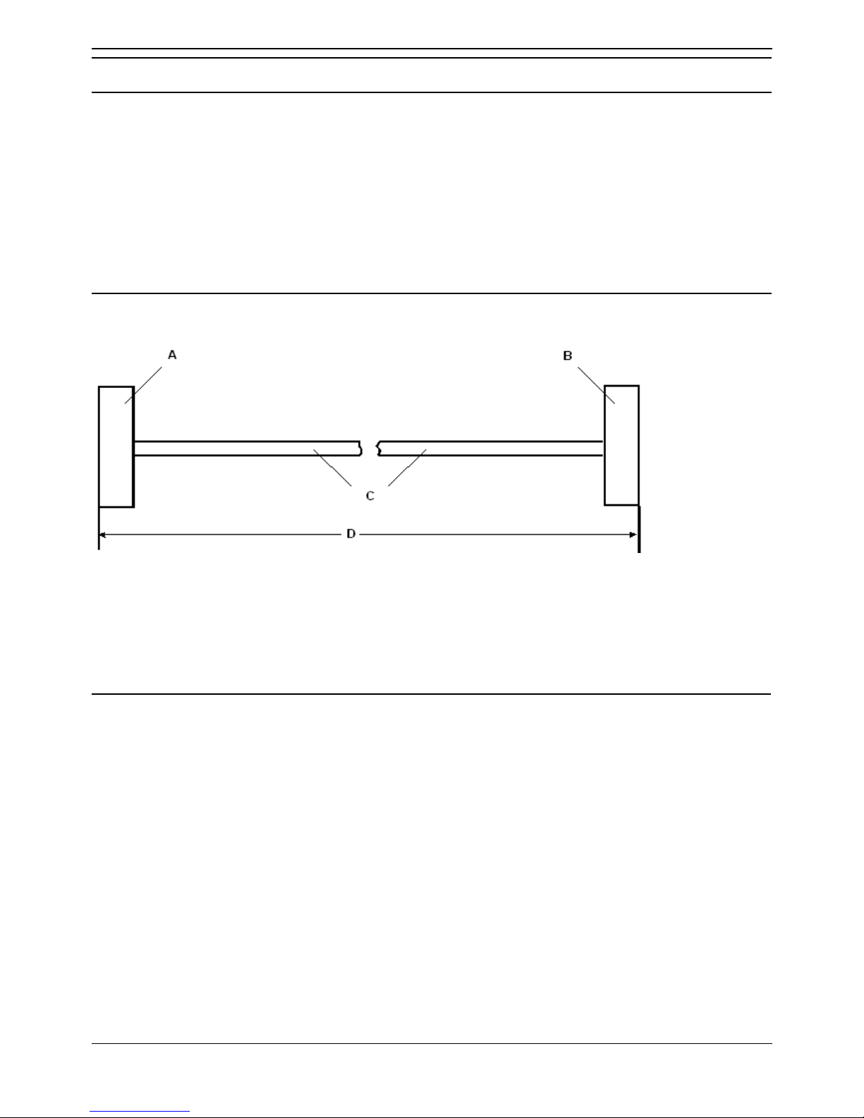
IP Office Installation
Installation Manual Page 84
IP Office 2.1 40DHB0002USCL Issue 10c (11th May 2004)
Cables
Cables
This section provides information about the cables that are used with IP Office. Refer to page 3 for port
pin out details. All of the following cables are for internal use only. All structured cabling/site wiring must
conform to all local regulations.
Cautions:
1. All ISDN and WAN cables should not be longer than 5 meters in length.
2. For Analog Trunk cables, to reduce the risk of fire, use only No. 26 AWG or larger
telecommunications line cord.
DTE Cable
SAP Code.:- 700213432 (25 Way)
A. 25 Way (or 9 Way on IP412) D-Type Plug with UNC 4-40 locking screws.
B. 9 Way D-Type Socket with UNC 4-40 locking screws.
C. 2 core screened cable - each core is 7/0.203mm (24 AWG) tinned copper stranded wire, nominal
capacitance of 95pF/m, resistance of 92 /km, screened with tinned copper braid, maximum
working voltage of 440V rms and a Maximum current per core of 1A rms
D. 2 meters/6.57ft.
Pin Connections
End A
(25 Way)
End A
(9 Way)
Name End B
2 3 Receive data 3
3 2 Transmit Data 2
4 7 RTS (Request To Send) 7
5 8 CTS (Clear To Send) 8
6 6 DSR (Data Set Ready) 6
7 5 Ground 5
8 1 DCD (Data Carrier Detect) 1
20 4 DTR (Data Terminal Ready) 4
22 9 RI (Ring Indicator) 9
Page 91
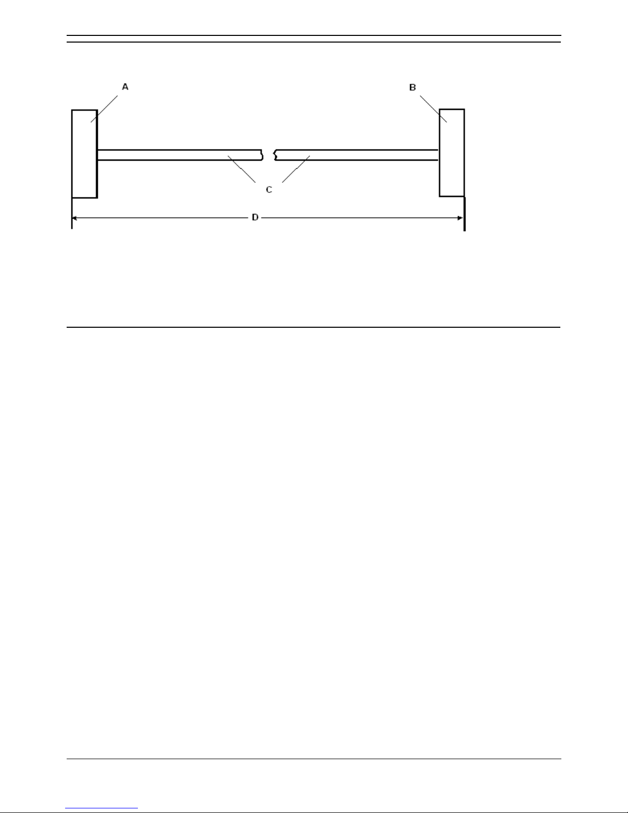
Technical Data
Installation Manual Page 85
IP Office 2.1 40DHB0002USCL Issue 10c (11th May 2004)
DT Line Cord for Structured Cabling
SAP Code.:- 700047871
A. RJ11 Plug.
B. RJ45 Plug.
C. Cable.
D. 4 meters/13.2ft.
Pin Connections
RJ11 Pin Number RJ45 Pin Number
3 5
4 4
• Caution:
Other connections may be present in cables and or structured cabling. For 4450DS modules, this
cable can be used to connect the module's PSU Line socket and the structured cabling. The
PSU's Tel socket must only be connected to the Line socket of the associated 4424D
telephone using the D4BU cable supplied with the PSU.
This cable can be used to replace the RJ11 to BT Newplan plug that is attached to the 20 series
telephones to allow connection to structured cabling.
Page 92
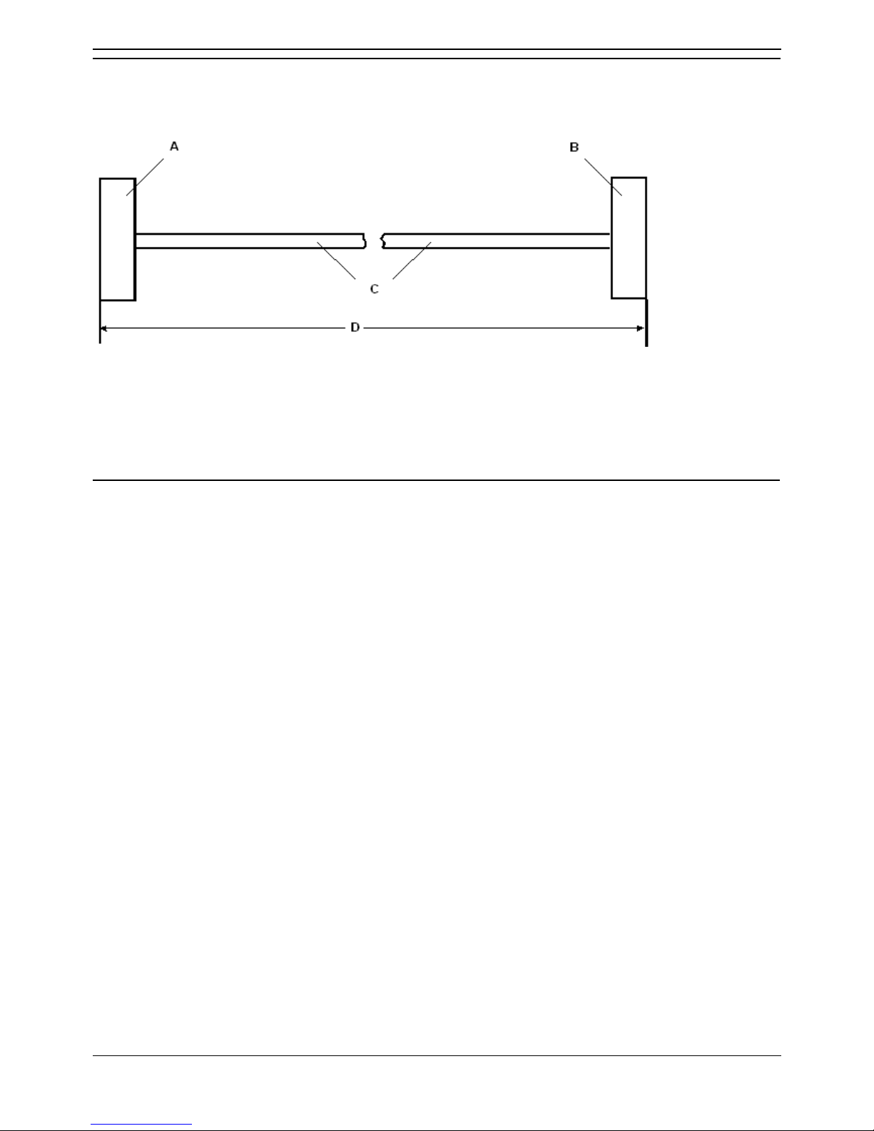
IP Office Installation
Installation Manual Page 86
IP Office 2.1 40DHB0002USCL Issue 10c (11th May 2004)
PRI/BRI ISDN Cable
SAP Code:- 700213440
Supply: As standard with IP Office systems.
A. RJ45 Plug.
B. RJ45 Plug.
C. Cat 5 UTP cable - RED.
D. 3 meters/9.84ft.
Pin Connections
End A BRI PRI Color Cable Notes End B
4 *Rx-A *Tx-A Blue/White Twisted pair 4
5 *Rx-B *Tx-B White/Blue Twisted pair 5
3 *Tx-A --- White/Green Twisted pair 3
6 *Tx-B --- Green/White Twisted pair 6
1 --- *Rx-A White/Orange Twisted pair 1
2 --- *Rx-B Orange/White Twisted pair 2
7 --- --- White/Brown Twisted pair 7
8 --- --- Brown/White Twisted pair 8
* With reference to the TE.
• Pins 7 and 8 are through connected for ease of construction. They are not actually used.
Page 93
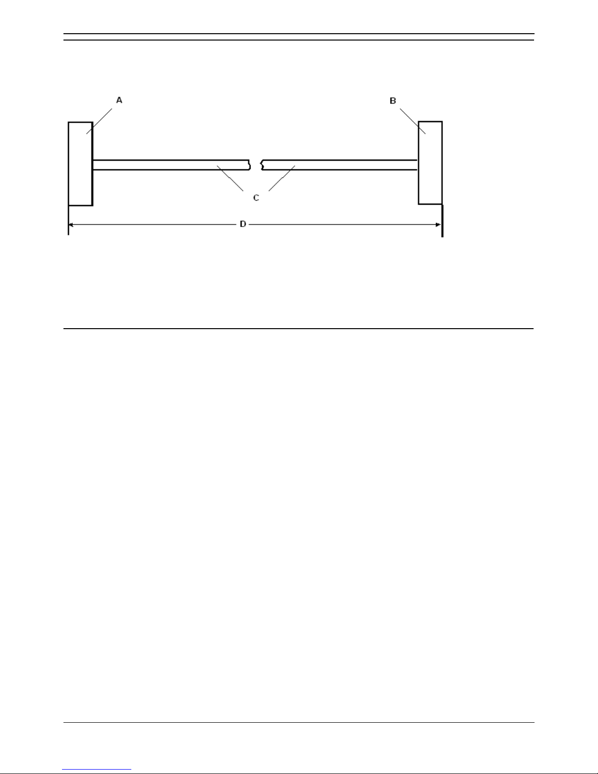
Technical Data
Installation Manual Page 87
IP Office 2.1 40DHB0002USCL Issue 10c (11th May 2004)
LAN Interconnect Cable
SAP Code:- 700213465
Supply: The cable is supplied with the WAN3 Expansion Module.
A. RJ45 Plug.
B. RJ45 Plug.
C. Cat 5 UTP cable - GREEN.
D. 1 meter/3.28ft.
Pin Connections
End A Color Cable Notes End B
1 White/Orange 1
2 Orange/White
Twisted Pair
2
3 White/Green 3
6 Green/White
Twisted Pair
4
4 Blue/White 5
5 White/Blue
Twisted Pair
6
7 White/Brown 7
8 Brown/White
Twisted Pair
8
• This cable is used:
• When connecting IP Office hub ports 1 - 7 directly to a PC.
• When connecting a WAN3 to an IP403/406 hub port which is located in the same cabinet
as the IP Office.
• Pins 4,5,7 and 8 are through connected for ease of construction. They are not actually used.
Page 94
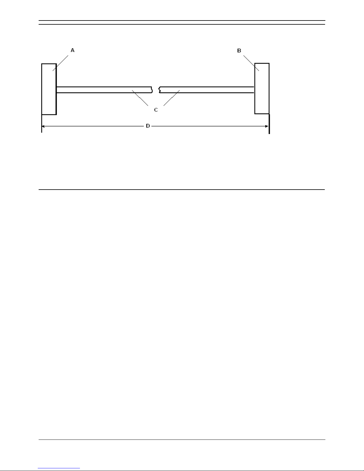
IP Office Installation
Installation Manual Page 88
IP Office 2.1 40DHB0002USCL Issue 10c (11th May 2004)
LAN Cable
SAP Code:- 700213481
A. RJ45 Plug.
B. RJ45 Plug.
C. Cat 5 UTP cable - GREY.
D. 3 meters/9.84ft.
Pin Connections
End A Color Cable Notes End B
1 White/Orange 1
2 Orange/White
Twisted Pair
2
3 White/Green 3
6 Green/White
Twisted Pair
6
4 Blue/White 4
5 White/Blue
Twisted Pair
5
7 White/Brown 7
8 Brown/White
Twisted Pair
8
• This cable is used:
• When connecting IP Office hub ports 1 - 7 directly to a PC.
• When connecting a WAN3 port to an IP403/406 hub port which is not located in the same
cabinet as the IP Office.
• Pins 4, 5, 7 and 8 are through connected for ease of construction. They are not actually used.
Page 95
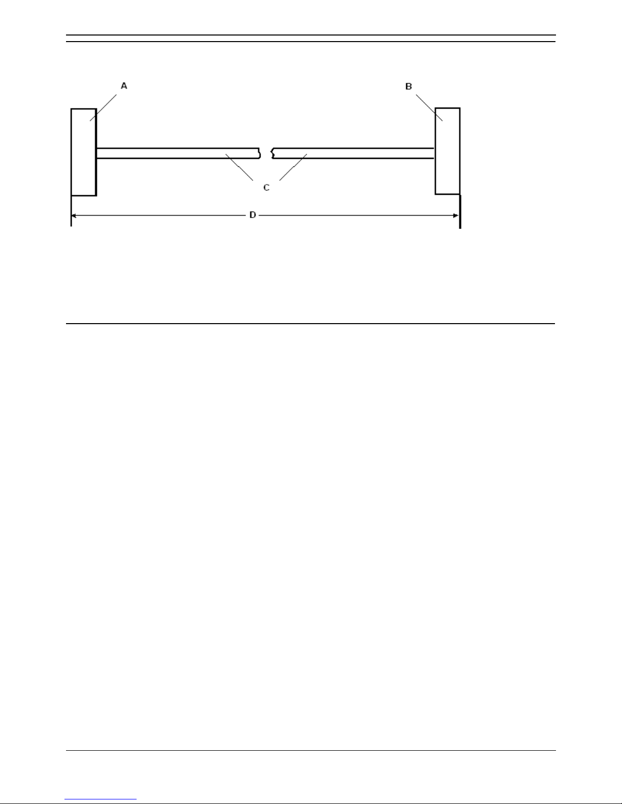
Technical Data
Installation Manual Page 89
IP Office 2.1 40DHB0002USCL Issue 10c (11th May 2004)
LAN Crossover Cable
SAP Code:- 700213473
A. RJ45 Plug.
B. RJ45 Plug.
C. Cat 5 UTP cross-over cable - BLACK.
D. 3 meters/9.84ft.
Pin Connections
End A Color Cable Notes End B
1 White/Orange 3
2 Orange/White
Twisted Pair
6
3 White/Green 1
6 Green/White
Twisted Pair
2
• This cable is used when connecting Hub Ports 1-7 directly to another Hub and for connecting a
WAN3 to an IP412.
Page 96
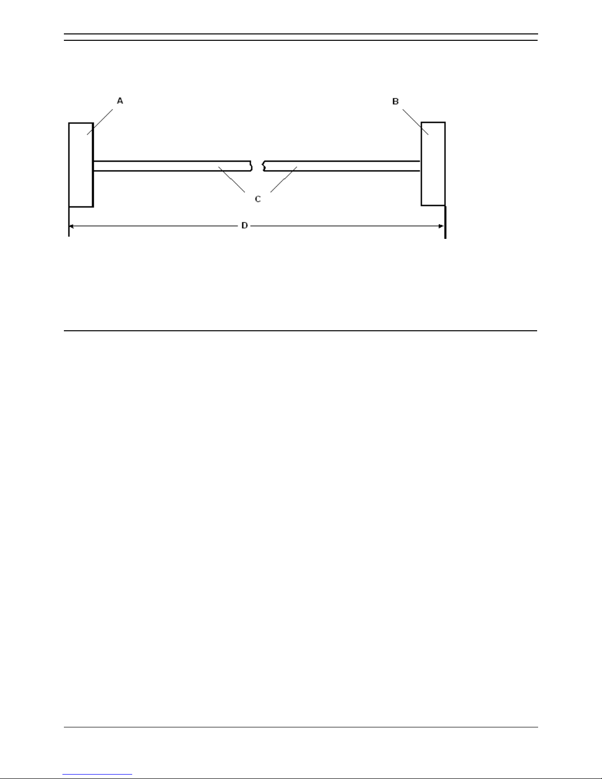
IP Office Installation
Installation Manual Page 90
IP Office 2.1 40DHB0002USCL Issue 10c (11th May 2004)
Expansion Interconnect Cable
SAP Code:- 700213457
Supply: One per Expansion Module.
A. Shielded RJ45 Plug.
B. Shielded RJ45 Plug.
C. STP (Shielded Twisted Pair) cable - BLUE.
D. 1 meter/3.28ft.
Pin Connections
End A Name Color Cable Notes End B
1 Rx-A White/Orange 1
2 Rx-B Orange/White
Twisted Pair
2
3 Sync-A White/Green 3
6 Sync-B Green/White
Twisted Pair
6
4 Clock-A Blue/White 4
5 Clock-B White/Blue
Twisted Pair
5
7 Tx-A White/Brown 7
8 Tx-B Brown/White
Twisted Pair
8
• The RJ45 Plug Shell at each end of the cable is connected to the STP Cable Drain Wire.
Page 97
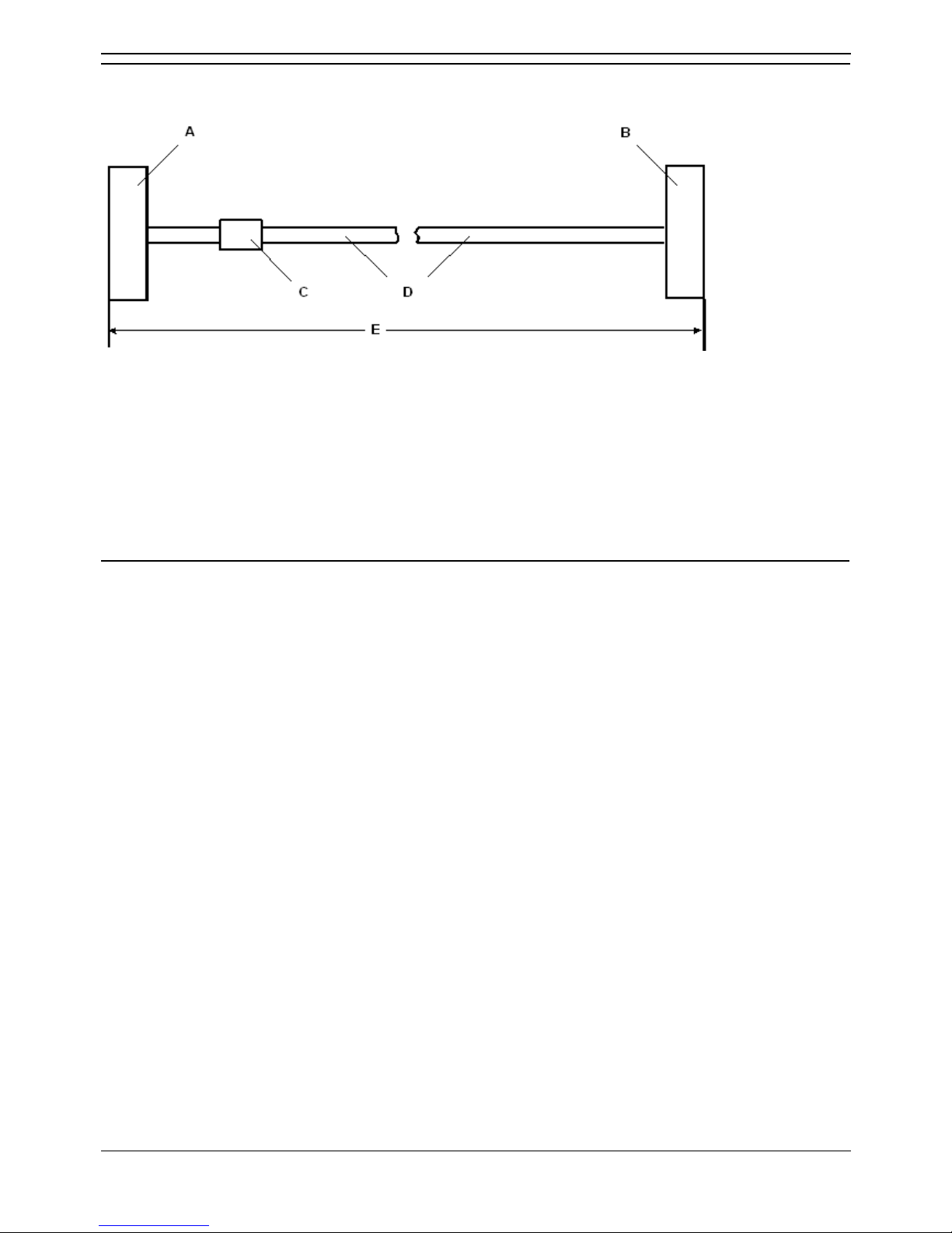
Technical Data
Installation Manual Page 91
IP Office 2.1 40DHB0002USCL Issue 10c (11th May 2004)
V.24/V.28 WAN Cable
SAP Code:- 700213416
A. 37 Way D-Type Plug with UNC 4-40 locking screws.
B. 25 Way D-Type Plug with UNC 4-40 locking screws.
C. Label
D. 12 core screened cable - each core is 7/0.203mm (24 AWG) tinned copper stranded wire,
nominal capacitance of 95pF/m, resistance of 92 /km, screened with tinned copper braid,
maximum working voltage of 440V rms and a Maximum current per core of 1A rms
E. 3 meters/9.84ft.
Pin Connections
End A Name End B
6 Ground 7
8 DTR (Data Terminal Ready) 20
9 Receive Data 3
10 Transmit Clock 15
11 DCD (Data Carrier Detect) 8
12 CTS (Clear To Send) 5
26 Transmit Data 2
27 RTS (Request To Send) 4
28 Receive Clock 17
29 RI (Ring Indicator) 22
30 DSR (Data Set Ready) 6
• Connect pin 25 to pin 6 at End A only.
• Pin 19 at end A is connected to the Screened Cable Drain Wire.
• The maximum core to core capacitance must not exceed 800pF.
• This cable is used to connect a WAN port to a Digital leased Line.
Page 98
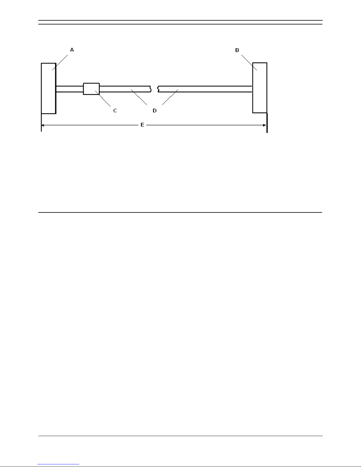
IP Office Installation
Installation Manual Page 92
IP Office 2.1 40DHB0002USCL Issue 10c (11th May 2004)
X.21 WAN Cable
SAP Code:- 700213408
A. 37 Way D-Type Plug with UNC 4-40 locking screws.
B. 15 Way D-Type Plug with M3 locking screws.
C. Label
D. 6 twisted pair screened cable - each core is 7/0.203mm (24 AWG) tinned copper stranded wire,
nominal capacitance of 98pF/m, impedance of 77 at 1MHz, screened with aluminized tape and a
tinned copper wire drain.
E. 3 meters/9.84ft.
Pin Connections
End A Name Cable Notes End B
1 Receive (Rx-B) 11
20 Receive (Rx-A)
Twisted Pair
4
4 Transmit (Tx-A) 2
23 Transmit (Tx-B)
Twisted Pair
9
24 Control (Ctl-A) 3
5 Control (Ctl-B)
Twisted Pair
10
2 Indicate (Ind-A) 5
21 Indicate (Ind-B)
Twisted Pair
12
3 SE-Timing (S-A) 6
22 SE-Timing (S-B)
Twisted Pair
13
6 Ground ------ 8
• Connect pin 7 to pin 6 at End A only.
• Pin 19 at end A is connected to the Screened Cable Drain Wire.
• This cable is used to connect a WAN port to a Digital leased Line.
Page 99
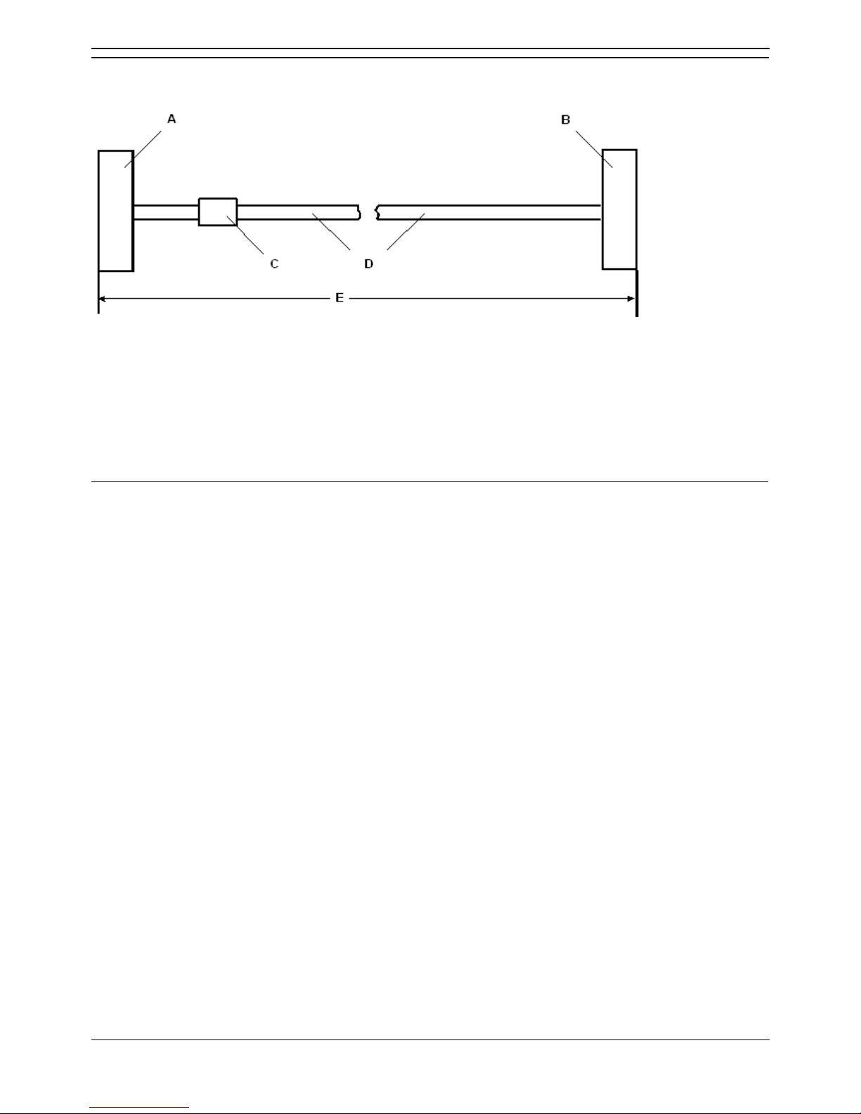
Technical Data
Installation Manual Page 93
IP Office 2.1 40DHB0002USCL Issue 10c (11th May 2004)
V.35 WAN Cable
SAP Code:- 700213424
A. 37 Way D-Type Plug with UNC 4-40 locking screws.
B. 34 Way MRAC Plug.
C. Label
D. 10 twisted pair screened cable - each core is 7/0.203mm (24 AWG) tinned copper stranded wire,
nominal capacitance of 98pF/m, impedance of 80 10% at 1MHz, screened with aluminized tape
and a tinned copper wire drain.
E. 3 meters/9.84ft.
Pin Connections
End A Name Cable Notes End B
8 DTR (Data Terminal Ready) ----- H
11 DCD (Data Carrier Detect) ----- F
12 CTS (Clear To Send) ----- D
27 RTS (Request To Send) ----- C
29 RI (Ring Indicator) ----- J
30 DSR (Data Set Ready) ----- E
32 Transmit Data - A P
14 Transmit Data - B
Twisted Pair
S
35 Receive Data - A R
16 Receive Data - B
Twisted Pair
T
36 Transmit Clock - A Y
17 Transmit Clock - B
Twisted Pair
AA
37 Receive Clock - A V
18 Receive Clock - B
Twisted Pair
X
33 External Clock - A U
15 External Clock - B
Twisted Pair
W
34 Ground ----- B
• Connect pins 7 and 25 to pin 6 at End A only.
• Pin 19 at end A is connected to the Screened Cable Drain Wire.
• The maximum core to core capacitance must not exceed 800pF.
• This cable is used to connect a WAN port to a Digital leased Line.
Page 100
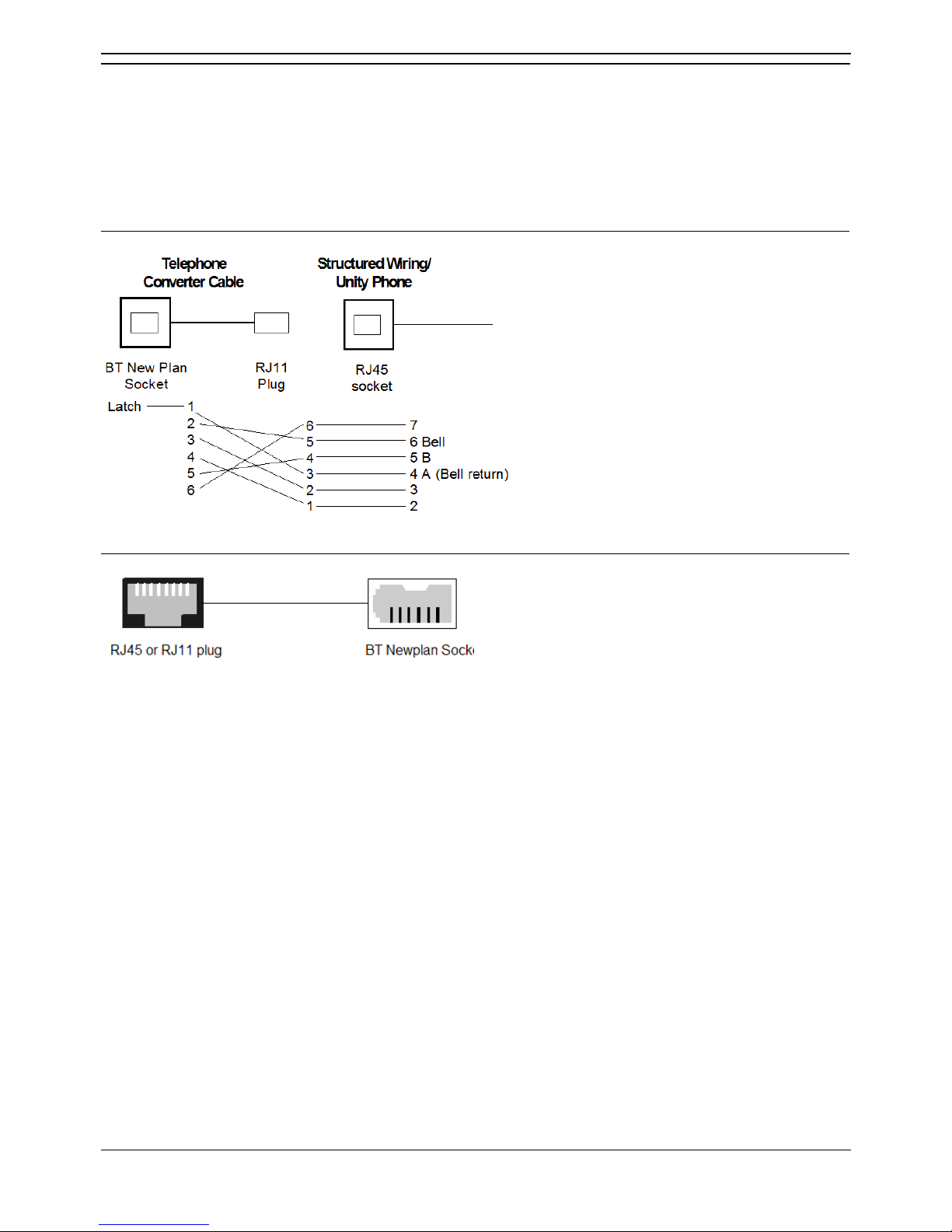
IP Office Installation
Installation Manual Page 94
IP Office 2.1 40DHB0002USCL Issue 10c (11th May 2004)
Telephone Converter Cables
The following diagrams show the pin-outs of various Structured Cabling Telephone Converters. The first
two telephone converters shown provide the required conversion allowing correct operation of the
attached telephone.
Each telephone port on the Phone modules acts as a Master socket, thus only Slave Telephone
Converters are required.
RJ45 - Compatible Converter
RJ11/45 Adapter
RJ11 Pin
Number
RJ45 Pin
Number
BT Newplan Socket Pin
Number
3 4 2
4 5 5
Other connections are not relevant. BT Newplan socket connections may be reversed as polarity is not
important. This adapter may be used with DT telephones fitted with BT Newplan plugs.
 Loading...