

Avaya ERS 4926GTS, ERS 4950GTS, ERS 4950GTS-PWR PLUS, ERS 4926GTS-PWR PLUS Installation Manual
You can download all documents referenced in this Quick Installation Guide at
www.avaya.com. You do not require a support contract to download documents.
When downloading documentation, select the specific software version. Depending on
your hardware model, your switch can appear different than the figures shown in this guide.
Confirm that you have the following tools and package contents:
Tools required:
• Phillips #2 screwdriver
• Console cable to match the console connector on the switch (RJ-45)
• Console cable or Ethernet cable (if using the default IP address to access the
device for configuration)
Package contents:
REPLACEMENT/OPTIONAL POWER SUPPLY UNITS
Primary PSU Optional Secondary PSU
ERS 4950GTS-PWR+,
ERS 4926GTS-PWR+
ERS 4950GTS,
ERS 4926GTS
250W AC power supply
(replacement order code:
AL1905?09-E6)
1025W AC POE+ power supply
(replacement order code:
AL1905?19-E6)
250W AC Power Supply
(order code: AL1905?09-E6)
1025W AC power supply
(order code: AL1905?19-E6)
Model
CABLES FOR INSTALLING THE SWITCH INTO A NETWORK
Name Short DescriptionPEC Code
AL2011022-E6 Avaya RJ-45/DB-9
CONSOLE CABLE
1.5m cable with DB-9 Female for
terminal/PC on one end and RJ-45
for device console port connectivity
on the other.
AL2011021-E6 AVAYA BLUE DB-9
MALE TO RJ-45
CONSOLE CONNECTOR
Converts DB-9 of AL2011013-E6
console cable to RJ-45, a Category 5
RJ-45 straight cable can then
connect to RJ-45 console port.
AL2011020-E6 AVAYA RED DB-9 FEMALE TO
RJ-45 ADAPTOR
Converts DB-9 MALE to RJ-45 serial
port. The adaptor can be used for PC
or device with DB-9 MALE console
port. Also, can be used with Category 5
RJ-45 straight cable to provide
console connection.
STACKING CABLES FOR STACKING
Description
700511668
700511669
700511670
700511671
0.5 m stacking cable
1.5 m stacking cable
3.0 m stacking cable
5.0 m stacking cable
Material code
Ethernet Routing
Switch 4900 Series
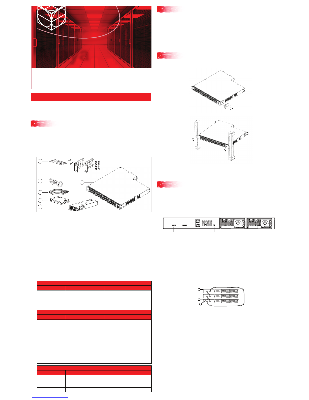
1. Avaya Ethernet Routing Switch 4900 Series.
2. Rack-mounting hardware that includes:
• Rack-mount brackets (2)
• Screws to attach brackets to the switch (8)
Note: Screws to attach the rack mount kit to rack are not provided.
3. AC power cord.
(Note: A power cord is not included for the A variant of the switch)
4. Standard .5 m stacking cable.
5. Documentation includes the Base software license kit, Quick Install poster,
and Regulatory documents.
6. Field replaceable power supply.
Note: Two field replaceable power supplies are supported for models ERS 4950GTS,
ERS 4926GTS, ERS 4950GTS-PWR+, and ERS 4926GTS-PWR+. One power supply is
already installed.
Note: Ensure to order Direct Attach cables and SFP or SFP+ Transceivers
if required.
Other optional requirements:
1. Provide the equivalent of one rack of vertical space for each switch in an EIA or
IEC-standard 19-inch (48.2-centimeter) equipment rack.
2. Ensure that the equipment rack is stable and securely attached to a
permanent structure.
3. Ground the rack to the same grounding electrode used by the power service in the
area. The ground path must be permanent and must not exceed 1 Ohm of
resistance from the rack to the grounding electrode. AVAYA recommends using a
filter or surge suppressor.
1.
Attach the brackets to each side of the device using the screws provided.
2. Slide the switch into the rack. Insert and tighten the rack-mount screws.
Avaya
1
Before you start
Quick Installation for Avaya Ethernet Routing Switch 4900 Series
2
3
Front-mount the switch in a rack
The Avaya ERS 4900 Series provides fail-safe stackability. You can connect up to eight 4900
Series devices in a stack to provide uninterrupted connectivity for up to 400 ports. The stack is
managed as single unit, using the IP address of the base unit.
ERS4900 series rear panel
The switch back panel provides a Base Unit Select switch, Cascade Down connector, and
Cascade Up connector for stacking purposes as shown below:
4
Stacking
Base Unit Select switch – used to designate the base unit in a stack. When set DOWN, this unit
acts as the Base Unit for the stack. Only one switch in the stack must have the Base Unit Select
in base position.
Ports – used for device management and cannot be used to access network (out-of-band
management). For more information, see Quick Start Configuration for Avaya Ethernet
Routing Switch 4900 and 5900 Series (NN47211-500)
Note: The port labeled AUX is disabled.
Cascade Down and Cascade Up connectors – used connect a switch to the next unit in the
stack through a cascade cable. Connect one end of the Cascade Down cable to the Cascade Up
connector of the next switch in the stack (shown in the simple two-switch stack connection block
diagram below):
Unit 1
Unit 2
Unit 3
1
2
3
Simplified Stacking diagram
1= Base unit
2= Last unit
3= Cascade/Stack Cable
Prepare the rack
To rear-mount the switch in a rack, see Installing the Avaya Ethernet Routing Switch
4900 Series, NN47212-301
3
5
4
CascadeUpCascade
Down
Base
Switch
Ports
To create a stack connection, order the appropriate Avaya ERS 4900 Series cascade cables to
ensure fail-safe stacking. For stacking three or more units (maximum eight units per stack),
order the cables as applicable (see other optional requirements).
1. Ensure that all switches for the stack are rack mounted.
2. Slide the Base Unit Select switches on the back of the units to the appropriate
position, depending on whether they are a base unit or non-base unit:
• Base Unit (Unit 1) - Slide the Base Unit Select switch DOWN
• Non-Base Unit (Units 2-8) - Slide the Base Unit Select switch UP.
Because stack parameters are associated with the base unit, the physical stack
order depends on the base unit position and whether you configure the stack
cascade up (stack up) or cascade down (stack down). This designation depends
on the stack cabling arrangement.
IMPORTANT: Avaya recommends you to use a Cascade Down configuration.
2
6
1
To set IP parameters using the console port and CLI Quickstart, perform the
following tasks:
http://support.avaya.com
1-800-242-2121 (U.S.A.)
1-866 GO-AVAYA
1-866-462-8292 (US Sales)
© 2016 Avaya Inc.
Poster part number: 700512439 Rev. 01
NN47212-300, 01.01
Recommended reading
For more information, go to http://support.avaya.com
and download the following ERS 4900 guides:
• Locating Documentation (NN47212-101)
• Regulatory Reference (NN47212-100)
• Documentation Reference for Avaya Ethernet Routing
Switch 4900 and 5900 Series (NN47211-103)
• Installing Avaya Ethernet Routing Switch
4900 Series (NN47212-301)
• Quick Start Configuration (NN47211–500)
• Configuring Systems (NN47211–501)
• Release Notes (NN47211-400)
ACLI boot and factory-default commands:
boot - reboot the switch
boot default - reboot and use the factory default configuration
boot partial-default - reboot and use the partial factory default configuration
restore factory-default - reset the switch to factory default configuration
Avaya Command Line Interface (ACLI)
You can manually load the ACLI script from the console menu or automatically load the
script at startup.
Connector Pin Number Signal
1
Ready to send (RTS) - optional
2 Data terminal ready (DTR) - optional
3 Transmit data (TXD) - mandatory
4 Carrier detect (DCD) - optional (provided on SR)
5 Ground (GND) - mandatory
6 Receive data (RXD) - mandatory
7 Data set ready (DSR) - optional
8 Clear to send (CTS) - optional (some sources indicated swapped with or tied to pin1)
Property Value
Baud Rate 9600 bps
Data Bits 8
Stop Bits 1
Parity None
Flow Control None
Terminal emulation settings
##########################################################################################################
Welcome to the ERS4900 setup utility.
You will be requested to provide the switch basic connectivity settings. After entering the requested
info, the configuration will be applied and stored into the switch NVRAM.
Once the basic connectivity settings are applied, additional configuration can be done using the available
management interfaces. Use Ctrl+C to abort the configuration at any time.
##########################################################################################################
Please provide the Quick Start VLAN <1-4094> [1]:
Please provide the in-band IP Address[172.16.120.20]:
Please provide the in-band sub-net mask[255.255.255.0]:
Please provide the Default Gateway[172.16.120.1]:
Please provide the management sub-net mask [0.0.0.0]:
Please provide the management IP address [0.0.0.0]:
Please provide the management Default Gateway [0.0.0.0]:
Please provide the Read-Only Community String[**********]:
Please provide the Read-Write Community String[**********]:
Please provide the in-band IPV6 Address/Prefix_length[::/0]:
Please provide the in-band IPV6 Default Gateway[::]:
Please provide the management IPv6 Address/Prefix length [::/0]:
Please provide the management IPv6 Default Gateway [::]:
##########################################################################################################
Basic switch parameters have now been configured and saved.
##########################################################################################################
Commissioning the ERS 4900
Command
Mode
Description Entrance
Commands
User Executive
(Exec mode)
4900>
• Default and Initial access code
• Requires only Read access
• Used for basic commands such
as show, ping, and logoff
Exit
Commands
No entrance command,
default mode
exit
or
logout
Privileged EXEC
(PrivExec mode)
4900#
• Used for basic switch level
management tasks; for example,
downloading software images, setting
passwords, starting the switch
• Default and Initial access mode
• Requires only Read access
enable exit
or
logout
Global
Configuration
(Config mode)
4900(config)#
• Used to set and display general
switch parameters such as IP
address, ANMP parameters,
Telnet access and VLANs
• Requires Read-Write access
From Privileged
EXEC mode, enter:
configure
exit
or
logout
Interface
Configuration
(ifconfig mode)
4900(config-if)#
• Used to set and display general
switch parameters such as IP
address, ANMP parameters,
Telnet access and VLANs
• Requires Read-Write access
From Global Configuration
mode, to configure a port, enter:
interface Ethernet
<port_number>
To configure a VLAN, enter:
interface vlan
<vlan_number>
To configure a loopback, enter:
interface loopback
<loopback number>
To configure a management,
enter:
interface mgmt
<mgmt number>
To return to
Global
Configuration
mode, enter:
exit
To return to
Privileged
EXEC mode,
enter:
end
To exit ACLI
completely,
enter:
logout
For more information on additional modes, see Using ACLI and EDM on Avaya ERS 4900
and 5900 Series (NN47211-104)
Manual configuration
Use the following ACLI command to manually configure the in-band management IP address:
ip address <A.B.C.D> [netmask <A.B.C.D>] [default-gateway <A.B.C.D>]
Example:
1. Enter Privileged Exec mode:
4900GTS>enable
2. Enter the Global Config mode:
4900GTS#config terminal
3. Manually configure in-band management IP information:
4900GTS(config)#ip address 192.0.2.1 netmask 255.255.255.0
default-gateway 192.0.2.0
4. Verify the information
4900GTS(config)show ipCommand Mode
Bootp/DHCP Mode: BootP When Needed
Configured In Use Last BootP/DHCP
---------- ------ --------------Stack IP Address: 0.0.0.0 0.0.0.0
Switch IP Address: 192.0.2.1 192.0.2.1 0.0.0.0
Switch Subnet Mask: 255.255.255.0 255.255.255.0 0.0.0.0
Mgmt Stack IP Address: 0.0.0.0
Mgmt Switch IP Address: 0.0.0.0
Mgmt Subnet Mask: 0.0.0.0
Mgmt Def Gateway: 0.0.0.0
Default Gateway: 192.0.2.0 192.0.2.0 0.0.0.0
8
Connect the console cable to the ERS 4900
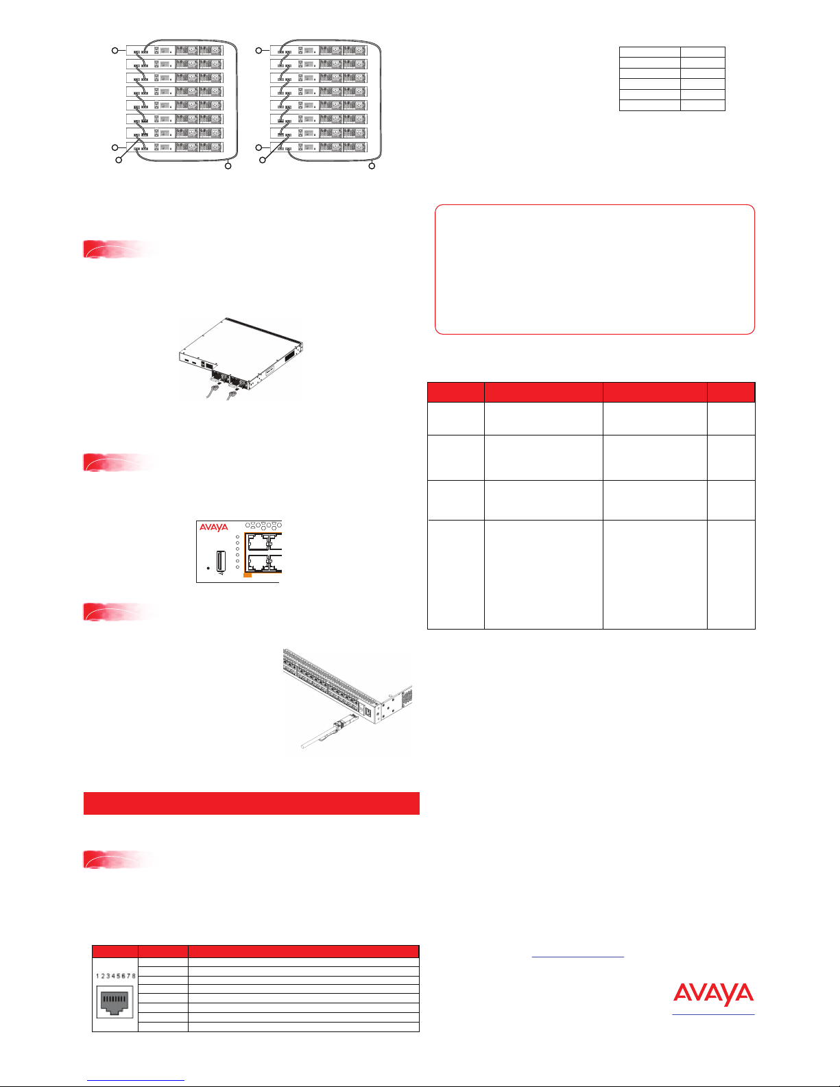
3. Connect stacking cables as required for a Cascade Up (stack up) or Cascade Down
(stack down) configuration as shown below:
Connect the AC power cord to the back of the switch, and then plug the other end of the cord into
an AC power outlet.
Warning: You must use a power cord set approved for the 4900 Series switch and the power
receptacle type in your country.
Ensure you have properly grounded the switch before powering up the unit.
The console port uses the RJ-45 port outlined with a blue border. Use an RJ-45 to DB-9 cable, or a
DB-9 to DB-9 serial cable to connect the switch console port to your management terminal.
Adapters are available to provide different connection options. The maximum length of a console
cable is 25 feet (8.3 meters). The following table describes the RJ-45 console port pin-out
information. You can use the pin-out information to verify or create a console cable for use with your
maintenance terminal.
1. Connect the console cable from the terminal to the console port of the switch to allow
initial configuration. Any terminal or PC with the appropriate terminal emulator can be
used as the management station.
2. Set the terminal protocol on the terminal
or terminal emulation program to
VT100 or VT100/ANSI.
3. Connect to the switch using the terminal
or terminal emulation application.
4. The Avaya switch banner appears when
you connect to the switch through the
Console port. There is no default password for the switch for CLI console access.
Enter Ctrl+Y and type the following CLI commands:
enable
install
5. The CLI Quickstart welcome screen helps you enter the information requested at
each prompt.
Note: The ERS 4900 uses the default IP address of 192.168.1.1/24 if the switch does
not get its IP address from another source. The default IP address is not applicable to
the out-of-band management port.
RJ–45 Console port pin assignments
5
Powering Up
The switch will power on immediately when it is connected to a suitable AC power source. The
switch does not have a power switch.
Check the front-panel LEDs as the device powers on to be sure the PWR LED is lit green. If not,
check if the power cord is correctly connected.
Status LEDs are on the left front side of the switch. For more information on all status LEDs, see
Installing Avaya ERS 4900 Series (NN47212-301).
6
Status LEDs
Before installing SFP and SFP+ transceivers, ensure the switch is up, fully booted, and operating
normally. Verify that the SFP or SFP+ transceivers and network cabling support your network
configuration.
Install SFP transceivers by performing this procedure.
1. Remove the transceiver from the protective packaging.
2. Verify that the transceiver is the correct model for the
network configuration.
3. Grasp the transceiver between your thumb and forefinger.
4. Insert the transceiver into the proper module on the switch.
Apply a light pressure to the transceiver until it clicks and
locks into position in the module.
7
Installing SFP and SFP+ transceivers
Cascade Down (Stack Down) configuration
1= Base unit
2= Last unit
3= Cascade/Stack Cable
4= Cascade/Stack Cable
(Return cable to make stack resilient.
Use longer stack cable if required.)
Unit 1
Unit 2
Unit 3
1
2
3
Unit 4
Unit 5
Unit 6
Unit 7
Unit 8
4
Cascade Up (Stack Up) configuration
1= Base unit
2= Last unit
3= Cascade/Stack Cable
4= Cascade/Stack Cable
(Return cable to make stack resilient.
Use longer stack cable if required.)
Unit 1
Unit 2
Unit 3
1
2
3
Unit 4
Unit 5
Unit 6
Unit 7
Unit 8
4
1
Speed/PoE+
Speed/PoE+
3
2 4
PoE+
USB
Status
PWR
RPS
Up
Down
Base
Reset
 Loading...