

Avaya ERS2526T-PWR, ERS2550T-PWR, ERS 3510GT-PWR+, ERS 3524GT-PWR+, ERS 3526T-PWR+ Technical Configuration Manual
...
Ethernet Routing Switch 2000, 3000, 4000 and 5000 Series
IP Office
Engineering
SME Solutions
IP Office & Ethernet Switching
Technical Configuration Guide
Avaya Networking
Document Date: October 2012
Document Number: NN48500-638
Document Version: 1.0

2
avaya.com
October 2012
© 2012 Avaya Inc.
All Rights Reserved.
Notices
While reasonable efforts have been made to ensure that the information in this document is complete and accurate at the time of
printing, Avaya assumes no liability for any errors. Avaya reserves the right to make changes and corrections to the information in
this document without the obligation to notify any person or organization of such changes.
Documentation disclaimer
Avaya shall not be responsible for any modifications, additions, or deletions to the original published version of this documentation
unless such modifications, additions, or deletions were performed by Avaya. End User agree to indemnify and hold harmless Avaya,
Avaya‘s agents, servants and employees against all claims, lawsuits, demands and judgments arising out of, or in connection with,
subsequent modifications, additions or deletions to this documentation, to the extent made by End User.
Link disclaimer
Avaya is not responsible for the contents or reliability of any linked Web sites referenced within this site or documentation(s)
provided by Avaya. Avaya is not responsible for the accuracy of any information, statement or content provided on these sites and
does not necessarily endorse the products, services, or information described or offered within them. Avaya does not guarantee that
these links will work all the time and has no control over the availability of the linked pages.
Warranty
Avaya provides a limited warranty on this product. Refer to your sales agreement to establish the terms of the limited warranty. In
addition, Avaya‘s standard warranty language, as well as information regarding support for this product, while under warranty, is
available to Avaya customers and other parties through the Avaya Support Web site: http://www.avaya.com/support
Please note that if you acquired the product from an authorized reseller, the warranty is provided to you by said reseller and not by Avaya.
Licenses
THE SOFTWARE LICENSE TERMS AVAILABLE ON THE AVAYA WEBSITE, HTTP://SUPPORT.AVAYA.COM/LICENSEINFO/
ARE APPLICABLE TO ANYONE WHO DOWNLOADS, USES AND/OR INSTALLS AVAYA SOFTWARE, PURCHASED FROM
AVAYA INC., ANY AVAYA AFFILIATE, OR AN AUTHORIZED AVAYA RESELLER (AS APPLICABLE) UNDER A COMMERCIAL
AGREEMENT WITH AVAYA OR AN AUTHORIZED AVAYA RESELLER. UNLESS OTHERWISE AGREED TO BY AVAYA IN
WRITING, AVAYA DOES NOT EXTEND THIS LICENSE IF THE SOFTWARE WAS OBTAINED FROM ANYONE OTHER THAN
AVAYA, AN AVAYA AFFILIATE OR AN AVAYA AUTHORIZED RESELLER, AND AVAYA RESERVES THE RIGHT TO TAKE
LEGAL ACTION AGAINST YOU AND ANYONE ELSE USING OR SELLING THE SOFTWARE WITHOUT A LICENSE. BY
INSTALLING, DOWNLOADING OR USING THE SOFTWARE, OR AUTHORIZING OTHERS TO DO SO, YOU, ON BEHALF OF
YOURSELF AND THE ENTITY FOR WHOM YOU ARE INSTALLING, DOWNLOADING OR USING THE SOFTWARE
(HEREINAFTER REFERRED TO INTERCHANGEABLY AS "YOU" AND "END USER"), AGREE TO THESE TERMS AND
CONDITIONS AND CREATE A BINDING CONTRACT BETWEEN YOU AND AVAYA INC. OR THE APPLICABLE AVAYA
AFFILIATE ("AVAYA").
Copyright
Except where expressly stated otherwise, no use should be made of the Documentation(s) and Product(s) provided by Avaya. All
content in this documentation(s) and the product(s) provided by Avaya including the selection, arrangement and design of the
content is owned either by Avaya or its licensors and is protected by copyright and other intellectual property laws including the sui
generis rights relating to the protection of databases. You may not modify, copy, reproduce, republish, upload, post, transmit or
distribute in any way any content, in whole or in part, including any code and software. Unauthorized reproduction, transmission,
dissemination, storage, and or use without the express written consent of Avaya can be a criminal, as well as a civil offense under
the applicable law.
Third Party Components
Certain software programs or portions thereof included in the Product may contain software distributed under third party agreements
("Third Party Components"), which may contain terms that expand or limit rights to use certain portions of the Product ("Third Party
Terms"). Information regarding distributed Linux OS source code (for those Products that have distributed the Linux OS source
code), and identifying the copyright holders of the Third Party Components and the Third Party Terms that apply to them is available
on the Avaya Support Web site: http://support.avaya.com/Copyright.
Trademarks
The trademarks, logos and service marks ("Marks") displayed in this site, the documentation(s) and product(s) provided by Avaya
are the registered or unregistered Marks of Avaya, its affiliates, or other third parties. Users are not permitted to use such Marks
without prior written consent from Avaya or such third party which may own the Mark. Nothing contained in this site, the
documentation(s) and product(s) should be construed as granting, by implication, estoppel, or otherwise, any license or right in and
to the Marks without the express written permission of Avaya or the applicable third party. Avaya is a registered trademark of Avaya
Inc. All non-Avaya trademarks are the property of their respective owners.
Downloading documents
For the most current versions of documentation, see the Avaya Support. Web site: http://www.avaya.com/support
Contact Avaya Support
Avaya provides a telephone number for you to use to report problems or to ask questions about your product. The support
telephone number is 1-800-242-2121 in the United States. For additional support telephone numbers, see the Avaya Web site:
http:// www.avaya.com/support.
IP Office & Ethernet Switching Technical Configuration Guide
Avaya Inc. – External Distribution

3
avaya.com
October 2012
Abstract
This Technical Configuration Guide describes a Small and Medium Enterprise (SME) solution comprised
of IP Office and Ethernet Routing Switch models. This solution integrates voice and data into one robust
and highly scalable network that is energy efficient, and easy to maintain.
Information in this Technical Configuration Guide has been obtained through interoperability testing in the
Avaya Networking Test Lab and additional technical discussions. The intended audience for this guide is
the Avaya Sales teams, Partner Sales teams and end-user customers.
Acronym Key
ADAC Auto Detection – Auto Configuration
AES Avaya Energy Saver
Codec Coder-Decoder program
DSCP Differentiated Services Code Point
ERS Ethernet Routing Switch
LLDP Link Layer Discovery Protocol
IPO IP Office
PD Powered Device
PoE Power over Ethernet
PSE Power Sourcing Equipment
QoS Quality of Service
SIP Session Initiation Protocol
IP Office & Ethernet Switching Technical Configuration Guide
Avaya Inc. – External Distribution

4
avaya.com
October 2012
Table of Contents
Figures .......................................................................................................................................................... 5
1. Introduction ........................................................................................................................................... 7
2. Ethernet Routing Switches and Features ............................................................................................. 8
2.1 ERS 2500 Series ......................................................................................................................... 13
2.2 ERS 3000 Series ......................................................................................................................... 14
2.3 ERS 4000 Series ......................................................................................................................... 15
2.4 ERS 5000 Series ......................................................................................................................... 18
2.5 Power over Ethernet ................................................................................................................... 19
2.6 Avaya Energy Saver ................................................................................................................... 20
3. IP Office .............................................................................................................................................. 20
4. Telephones Tested with this Solution ................................................................................................. 20
4.1 Avaya 9600 Series IP Phones .................................................................................................... 21
4.2 Avaya 1600 Series IP Phones .................................................................................................... 21
4.3 Avaya 4600 Series IP Phones .................................................................................................... 21
4.4 Avaya 1400 Series Digital Phones .............................................................................................. 21
5. Equipment and Software Validated ..................................................................................................... 22
6. Testing Methodology ........................................................................................................................... 23
7. Connectivity Tests ............................................................................................................................... 24
7.1 Connectivity Test Results ............................................................................................................ 25
7.2 ERS Connectivity Configuration .................................................................................................. 26
7.2.1 Auto Configuration .................................................................................................................................. 26
7.2.2 Configuring ADAC and LLDP ................................................................................................................. 27
7.2.3 Configuring PoE ..................................................................................................................................... 29
7.2.4 Verifying QoS Settings ........................................................................................................................... 32
7.2.5 Configuring AES ..................................................................................................................................... 34
8. IP Office Telephony Tests ................................................................................................................... 39
8.1 IP Office Test Results ................................................................................................................. 39
8.2 IP Office Configuration ................................................................................................................ 40
8.2.1 IP Office Script ....................................................................................................................................... 41
8.2.2 Accessing IP Office Manager ................................................................................................................. 44
8.2.3 Verifying Differentiated Services ............................................................................................................ 45
8.2.4 Enabling DHCP Server ........................................................................................................................... 46
8.2.5 Verifying IP Telephone Extensions......................................................................................................... 47
8.2.6 Verifying the Direct Media Path .............................................................................................................. 47
9. Conclusion .......................................................................................................................................... 48
IP Office & Ethernet Switching Technical Configuration Guide
Avaya Inc. – External Distribution

5
avaya.com
October 2012
Figures
Figure 1 – ERS 2500 series PoE switches ................................................................................................. 13
Figure 2 – ERS 3500 series PoE switches ................................................................................................. 14
Figure 3 – ERS 4000 series PoE switches ................................................................................................. 16
Figure 4 – ERS 4000 series PoE+ switches ............................................................................................... 17
Figure 5 – ERS 5000 series PoE switches ................................................................................................. 18
Figure 6 – Branch Office Test Bed Topology .............................................................................................. 23
Tables
Table 1 – PoE Ethernet Routing Switches .................................................................................................... 9
Table 2 – ERS 4500/4800 PoE/PoE+ power budgets ................................................................................ 15
Table 3 - Connectivity Test Results ............................................................................................................ 25
Table 4 – IP Office Test Results ................................................................................................................. 40
IP Office & Ethernet Switching Technical Configuration Guide
Avaya Inc. – External Distribution

6
avaya.com
October 2012
Symbols
Tip – Highlights a configuration or technical tip.
Note – Highlights important information to the reader.
Warning – Highlights important information about an action that may result in equipment
damage, configuration or data loss.
Text
Bold text indicates emphasis.
Italic text in a Courier New font indicates text the user must enter or select in a menu item, button or
command:
ERS5520-48T# show running-config
Output examples from Avaya devices are displayed in a Lucida Console font:
ERS5520-48T# show sys-info
Operation Mode: Switch
MAC Address: 00-12-83-93-B0-00
PoE Module FW: 6370.4
Reset Count: 83
Last Reset Type: Management Factory Reset
Power Status: Primary Power
Autotopology: Enabled
Pluggable Port 45: None
Pluggable Port 46: None
Pluggable Port 47: None
Pluggable Port 48: None
Base Unit Selection: Non-base unit using rear-panel switch
sysDescr: Ethernet Routing Switch 5520-48T-PWR
HW:02 FW:6.0.0.10 SW:v6.2.0.009
Mfg Date:12042004 HW Dev:H/W rev.02
Conventions
This section describes the text, image, and command conventions used in this document.
Avaya Inc. – External Distribution
IP Office & Ethernet Switching Technical Configuration Guide

7
avaya.com
October 2012
1. Introduction
Networks serve an increasingly diverse community of users and connect a wide assortment of devices.
For example, your network may include laptops, mobile phones, office phones, and an explosion of ―bring
your own devices‖ (BYOD). Because network administrators are constantly struggling to manage the
demands on their networks, Avaya developed the Small and Medium Enterprise (SME) solution with
IP Office and Ethernet Switching.
The SME solution is all you need for your entire business infrastructure. This solution is not only easy to
install and maintain, it combines all the strengths of Avaya‘s industry-leading Ethernet Routing Switches
with IP Office. This solution integrates the VoIP and data traffic into one network thus eliminating the
need to maintain separate voice and data networks.
Ethernet Routing Switches are powerful standalone switches, but their stacking capability makes
them future proof. As your needs grow, you can add another switch to the stack. Many ERS
models support Power over Ethernet (PoE) and PoE+ to provide power directly to endpoints over
the Ethernet cable. The innovative Avaya Energy Saver provides added intelligence to reduce
power consumption of the network during non-peak hours.
IP Office combines the reliability of a traditional telephony system with the application advantages
of an IP telephony solution. With IP Office almost any phone can become an office extension.
This enables you to collaborate on conference calls, get detailed reports, use email, and send
text or instant messages.
With the SME solution, you can build a scalable, integrated voice and data network that is energy efficient
and easy to maintain. And as the interoperability testing demonstrated, the ERS switches provide the
benefits of PoE and meet users‘ expectations for quality of service (QoS).
For detailed information about Ethernet Routing Switches, PoE, and IP Office, please refer to the
technical documentation available on the Avaya Web site at http://www.avaya.com/support.
IP Office & Ethernet Switching Technical Configuration Guide
Avaya Inc. – External Distribution
8
avaya.com
October 2012
Note – All of the following PoE switches have power saving features, but only the ERS 4000
Series supports Avaya Energy Saver (AES).
Switch Model
Ports on PoE switches
Ethernet Routing Switch 2500 series
2526T-PWR
24x 10/100 ports, 12 PoE capable ports, plus 2x 10/100/1000 or SFP
combo ports.
2550T-PWR
48x 10/100 ports, 24 PoE capable ports, plus 2x 10/100/1000 or SFP
combo ports.
NOTE: Each ERS2500 also has 2x rear 1000Mbps ports that can
be used as additional user ports or stacking ports.
Ethernet Routing Switch 3500 series
3526T-PWR+
24x 10/100 PoE/PoE+ ports, plus 2x 10/100/1000 or SFP combo
ports.
3510GT- PWR+
8x 10/100/1000 PoE/PoE+ ports, plus 2x SFP ports.
3524GT- PWR+
24x 10/100/1000 PoE/PoE+ ports with 4x SFP combo ports shared
with ports 21-24.
NOTE: Each ERS3500 also has 2x rear SFP ports that can be
used as additional user ports or stacking ports (stacking is
supported from software release v5.1 – Feb 2013.
Ethernet Routing Switch 4000 series
4526T-PWR
24x 10/100 PoE ports, plus 2x 10/100/1000 or SFP combo ports.
4550T-PWR
48x 10/100 PoE ports, plus 2x 10/100/1000 or SFP combo ports.
4526T-PWR+
24x 10/100 PoE/PoE+ ports, plus 2x 10/100/1000 or SFP combo
ports.
4550T-PWR+
48x 10/100 PoE/PoE+ ports, plus 2x 10/100/1000 or SFP combo
ports.
4524GT-PWR
24x 10/100/1000 PoE ports with 4x SFP combo ports shared with
ports 21-24.
2. Ethernet Routing Switches and Features
Depending on your needs for PoE, PoE+, redundant power, and configurable energy savings, you can
choose PoE models from any of these platforms as the underlying Ethernet infrastructure of this solution.
Avaya Inc. – External Distribution
IP Office & Ethernet Switching Technical Configuration Guide

9
avaya.com
October 2012
4526GTX-PWR
24x 10/100/1000 PoE ports plus 2x XFP 10GbE ports.
4548GT-PWR
48x 10/100/1000 PoE ports with 4x SFP combo ports shared with
ports 45-48.
4826GTS-PWR+
24x 10/100/1000 PoE/PoE+ ports, 2 shared SFP ports, plus 2x SFP+
ports.
4850GTS-PWR+
48x 10/100/1000 PoE/PoE+ ports, 2 shared SFP ports, plus 2x SFP+
ports.
Ethernet Routing Switch 5000 series
5520-24T-PWR
24x 10/100/1000 PoE ports with 4x SFP combo ports shared with
ports 21-24.
5520-48T-PWR
48x 10/100/1000 PoE ports with 4x SFP combo ports shared with
ports 45-48.
5650TD-PWR
48x 10/100/1000 PoE ports with 6x SFP combo ports shared with
ports 43-48, plus 2x XFP ports.
5698TFD-PWR
96x 10/100/1000 PoE ports with 6x SFP combo ports shared with
ports 91-46, plus 2x XFP ports.
Important: All units in the stack must be from the same product family and use the same
software version.
Software Release
Feature
Ethernet Routing Switch 2500 series
4.1
ADAC via MAC
4.1
ADAC via 802.1AB
4.2
802.1AB MED
4.4
ADAC Enhancement (8 uplinks/call server ports and change non-ADAC
VLANs)
Table 1 – PoE Ethernet Routing Switches
Ethernet Routing Switches (ERS) can operate as standalone units. However, as your network needs
grow, you can create stacks of up to eight units each. Stacking provides management efficiency; you
manage a stack with a single IP address, as a single virtual switch, and software is available as a single
image across all models in the stack. For example, if you create a stack with eight ERS 2550T-PWR
switches, a total of 192 PoE ports is available, each capable of providing data, voice, and power to
devices in your network, and you would manage those ports within a single configuration, as one virtual
switch.
Avaya Inc. – External Distribution
IP Office & Ethernet Switching Technical Configuration Guide

10
avaya.com
October 2012
4.0
Simple Network Time Protocol (SNTP) with Timezone support
4.4
802.1AB Integration
Ethernet Routing Switch 3500 series
5.0
ADAC via MAC
5.0
ADAC via 802.1AB
5.0
802.1AB MED
5.0
ADAC Enhancement (8 uplinks/call server ports and change non-ADAC
VLANs)
5.0
802.1AB Integration
5.0
802.1AB Defaults
5.0
Simple Network Time Protocol (SNTP) with Timezone support
Ethernet Routing Switch 4000 series
5.1
ADAC via MAC
5.1
ADAC via 802.1AB
5.2
802.1AB MED
5.6
802.1AB MED Integration (decoupled from ADAC)
5.4
ADAC Enhancement (8 uplinks/call server ports and change non-ADAC
VLANs)
5.5
802.1AB Integration
5.6
802.1AB Defaults
5.6
Avaya Energy Saver with SNTP and NTP Support
5.6
Voice VLAN Integration
5.0
Simple Network Time Protocol (SNTP) with Timezone support
5.6
Network Time Protocol (NTP)
Ethernet Routing Switch 5500 series
5.0
ADAC via MAC
5.1
ADAC via 802.1AB
Avaya Inc. – External Distribution
IP Office & Ethernet Switching Technical Configuration Guide

11
avaya.com
October 2012
5.0
802.1AB MED
6.3
802.1AB MED Integration (decoupled from ADAC)
6.2
ADAC Enhancement (8 uplinks/call server ports and change non-ADAC
VLANs)
6.3
802.1AB Integration
6.2
Avaya Energy Saver with SNTP Support
4.10
SNTP
5.10
SNTP with Timezone support
Ethernet Routing Switch 5600 series
6.0
ADAC via MAC
6.0
ADAC via 802.1AB
6.0
802.1AB MED
6.3
802.1AB MED Integration (decoupled from ADAC)
6.2
ADAC Enhancement (8 uplinks/call server ports and change non-ADAC
VLANs)
6.3
802.1AB Integration
6.2
Avaya Energy Saver with SNTP Support
6.0
SNTP with Timezone support
Features
Voice VLAN Integration
Voice VLAN Integration offers a unified concept of Voice VLAN through various applications
(ADAC, EAP and LLDP).
Voice VLAN Integration feature enhances the functionality of ADAC and removed many
limitations which resulted in the Voice VLAN being dynamically allocated.
This now means that any VLAN functions can be assigned to the Voice VLAN, such as Layer 3 or
static port assignments.
Avaya Inc. – External Distribution
IP Office & Ethernet Switching Technical Configuration Guide

12
avaya.com
October 2012
802.1AB Integration
802.1AB Integration provides the ability to configure 802.1AB (LLDP) parameters to allow
improved provisioning of Avaya IP handsets
Support for Avaya proprietary 802.1AB (LLDP) TLVs, which include:
802.1AB Defaults
The 802.1AB New Default Parameters feature will change default 802.1AB (LLDP)
parameters to improved day 1 out of the box operation for Voice and UC applications.
The New default values should be the equivalent of:
o Enables the switch to provision the Phone via TLVs rather than DHCP/TFTP method
o Improved provisioning capabilities by allowing the switch to configure: call-server, file-
server, poe-conservation, dot1q-framing
o The switch can report on currently used parameters per port as well as listing the
Phones in-use IP parameters.
o Integrates with Avaya Energy Saver, so that when Energy Saver is activated, the
poe-conservation parameter is dynamically changes to maximum to drive further
power savings.
4500 (config-if) # lldp config-notification
4500 (config-if) # lldp status txAndRx config-notification
4500 (config-if) # lldp tx-tlv local-mgmt-addr port-desc sys-desc sys-name
4500 (config-if) # ldp tx-tlv dot3 mdi-power-support
4500 (config-if) #lldp tx-tlv med extendedPSE inventory location med-capabilities network-
policy
4500 (config) # lldp med-network-policies voice dscp 46 priority 6
For more information about Ethernet Routing Switches, see the technical documentation available on the
Avaya Web site at http://www.avaya.com/support.
IP Office & Ethernet Switching Technical Configuration Guide
Avaya Inc. – External Distribution
13
avaya.com
October 2012
2.1 ERS 2500 Series
Avaya Ethernet Routing Switch 2500 series includes a range of energy-efficient, Fast Ethernet switches
suitable for branch office and entry-level enterprise wiring closet deployments. ERS 2500 Series switches
offer intelligent stacking, virtual hot swap for in-service maintenance and restoration, and include
automatic QoS, Power over Ethernet (PoE), simple IP Phone deployments, and a wide range of flexible
security options.
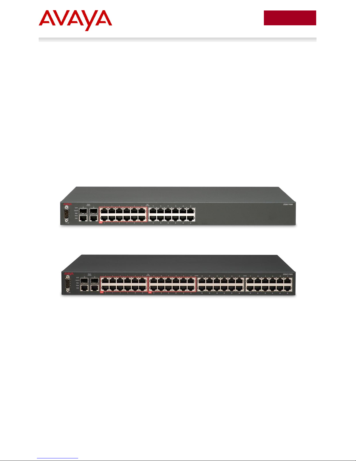
The ERS 2550T-PWR and 2526T-PWR provide IEEE 802.3af-compliant (PoE, 15.4W) power on half the
ports, and are contained with a RED line surrounding the ports supporting PoE. These switch models
provide power discovery, power management, and power use statistics per port and per switch and do
not support Avaya Energy Saver. ERS2500 PoE model switches only support PoE on the lowernumbered ports, and provide a total PoE budget of 168W per switch.
The ERS 2500 switches optimize power consumption. You can configure each port to a power priority
level of low, high, or critical, limiting the amount of power delivered to non-business-critical devices.
Figure 1 – ERS 2500 series PoE switches
ERS2526T-PWR
ERS2550T-PWR
IP Office & Ethernet Switching Technical Configuration Guide
Avaya Inc. – External Distribution
14
avaya.com
October 2012
2.2 ERS 3000 Series
The Avaya Ethernet Routing Switch 3500 Series are high-performance, compact Ethernet switches
designed for small branch offices (typically 100 users or less). The ERS 3500 includes 10-port and 24port 10/100/1000BaseT models, and 24-port 10/100BASE-TX models.
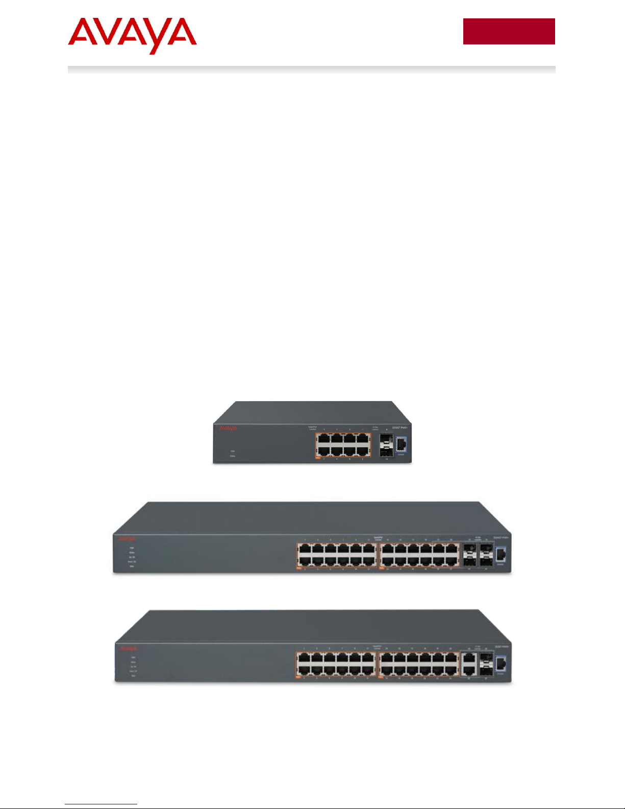
The ERS 3510GT-PWR+, 3524GT-PWR+ and 3526T-PWR+ provide IEEE 802.3af-compliant (PoE,
15.4W) or 802.3at-compliant (PoE+, 32W) power on all ports, and are contained with an ORANGE line
surrounding the PoE ports.
ERS3500 PoE+ model switches support the following maximum power budget per switch:
- 3510GT-PWR+, 60Watts maximum in Low power budget mode (fanless operation), or 170W
maximum in High power budget mode (normal fan operation).
- 3524GT-PWR+ and 3526T-PWR+, 370Watts per switch maximum.
When you use ERS 35xx-PWR+ units, you can plug any powered device into a compliant front-panel port
and receive power in that port. ERS3500 series PoE switches do not yet support the Avaya Energy Saver
(AES) feature, but this is planned in a near future release.
The 24-port models will support stacking with the 5.1 release targeted for availability in February 2013.
Stack cables are sold separately to provide resilient stacking capability of up to 8 units in a stack with
software v5.1 running on the 24-port switches.
Figure 2 – ERS 3500 series PoE switches
ERS 3510GT-PWR+
ERS 3524GT-PWR+
IP Office & Ethernet Switching Technical Configuration Guide
ERS 3526T-PWR+
Avaya Inc. – External Distribution
15
avaya.com
October 2012
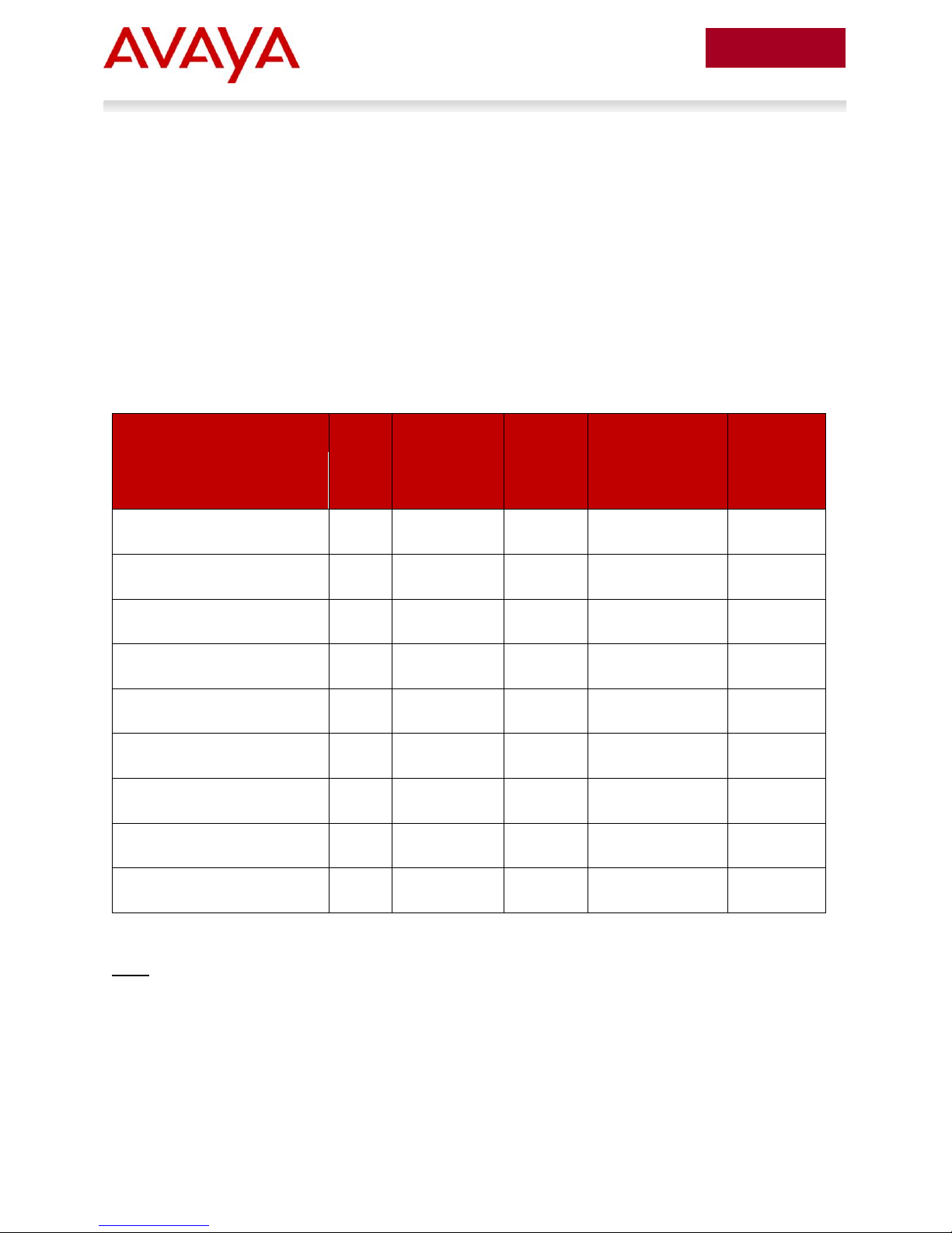
Switch Model
PoE
Ports
PoE budget
(Watts, when
using primary
AC power)
Average
per port
(Watts)
PoE budget
(Watts, with primary
AC power supply
plus RPS15 or
secondary PSU)
Average
per port
(Watts)
4526T-PWR
24
370
15.4
370
15.4
4550T-PWR
48
370
7.7
740
15.4
4524GT-PWR
24
360
15.0
370
15.4
4548GT-PWR
48
320
6.7
740
15.4
4526GTX-PWR
24
360
15.0
370
15.4
4526T-PWR+
24
778
32.4
778
32.4
4550T-PWR+
48
855
17.8
1555
32.4
4826GTS-PWR+
24
778
32.4
778
32.4
4850GTS-PWR+
48
855
17.8
1555
32.4
2.3 ERS 4000 Series
The Avaya Ethernet Routing Switch 4000 Series contains 4500 and 4800 series models and is designed
for enterprise wiring closets and other network edge deployments. This stackable chassis system
provides Layer 2 switching and dynamic Layer 3 routing, convergence features, high performance, and
secure and resilient Ethernet switching connectivity. The Avaya Ethernet Routing Switch 4500/4800
Series switch models support 10/100 and 10/100/1000 switching and routing, PoE, PoE+, and 10 GbE
uplink options.
The ERS4000 series models designated with ―PWR‖ provide IEEE 802.3af-compliant (PoE, 15.4W), while
models designated with ―PWR+‖ provide both 802.3af (PoE) or 802.3at-compliant (PoE+, 32W) power on
all ports, and are contained within a RED (PoE models) or ORANGE (PoE+ models) line surrounding the
PoE ports.
ERS4000 series PoE model switches support the following maximum power budget per switch:
Table 2 – ERS 4500/4800 PoE/PoE+ power budgets
Note: ERS4500 ―PWR‖ (PoE) models support a Redundant Power Supply 15 (RPS15) connection at the
rear for DC power redundancy, or, for power load sharing which provides additional PoE power if
required. Newer model ERS4500/4800 ―PWR+‖ (PoE+) models use separate pluggable power supply
modules at the rear and do not support RPS15 connection. 300W and 1000W removable power supply
modules are available for these models.
When you use ERS 4500 PWR and 4500/4800 PWR+ units, you can plug any powered device into a
compliant front-panel port and receive power in that port. All ERS 4000 series PoE switches support the
Avaya Energy Saver (AES) feature.
IP Office & Ethernet Switching Technical Configuration Guide
Avaya Inc. – External Distribution
 Loading...