

Avaya ERS 3510GT-PWR+, ERS 3510GT, ERS 3524GT-PWR+, ERS 3524GT, ERS 3526T Quick Install Manual
...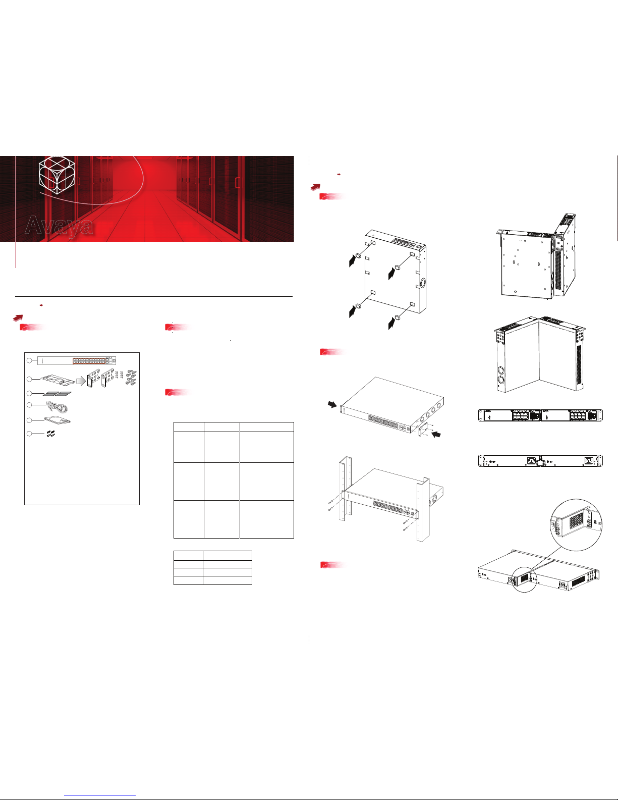
To rack mount a pair of ERS 3510GT or ERS 3510GT-PWR+ switches:
Use the 3510-Pair Rack Mount Accessory Kit (AL3511002-E6) to mount two ERS
3510GT or ERS 3510GT-PWR+ switches together side-by-side in a standard
19” rack.
Note: When mounting two 3510GT-PWR+ units side by side in an equipment rack,
run the switches in high power mode to ensure adequate airflow.
1. Ensure power is disconnected from the switch.
2. Connect the two ERS 3510GT switches together by opening the hinged bracket
to 90° and attaching it to each ERS 3510GT switch with three M4 flat head
screws (included), as shown below.
3. Attach the standard rack mount bracket ears to the outer end of each switch as
shown below.
4. Once the switches are joined together, fold the hinged bracket inward.
Steps 1 3
Before you start
Steps 4 6
Mounting Options
All documents referenced in this Quick Installation Guide can be downloaded at www.avaya.com.
Depending on your hardware model, your switch may appear different than the figures shown in this guide.
1
3
5a
5b
Rack mounting - ERS 3524GT, ERS 3524GT-PWR+,
ERS 3526T, or ERS 3526T-PWR+
Rack mounting pairs ERS 3510GT or ERS 3510GT-PWR+
2
4
1
5
6
3
3526T-PWR+
Confirm that you have the tools and package contents as follows:
Tools Required:
• Phillips #2 screwdriver
Package Contents:
1. Avaya Ethernet Routing Switch 3500 Series
2. Rack-mounting hardware that includes:
(not applicable to ERS 3510GT or ERS 3510GT-PWR+)
• Rack-mount brackets (2)
• Screws to attach brackets to the switch (8)
• Screws to attach the switch to the equipment rack (2x4)
3. Rubber footpads (ERS 3510GT and ERS 3510GT-PWR+ only)
4. AC power cord
(Note: a power cord is not included for the A variant of the switch)
5. Base Software License Kit
6. Screws (2) and wall anchors (2) for wall mounting
(ERS 3510GT and ERS 3510GT-PWR+ only)
Depending on your installation, the following accessory kits may
be required:
• One 3510-Pair Rack Mount Kit — this accessory kit is used to connect two
ERS 3510GT or ERS 3510GT-PWR+ switches together side-by-side and
mount them in a 19 inch rack. The kit includes all necessary brackets and
fasteners and must be ordered separately (Order Code AL3511002-E6)
• One Spare Rack Mount Kit – this kit can be used to mount an ERS 3510GT
or ERS 3510GT–PWR+ under a desk or on to another surface. This kit is
also used as a replacement rack mount kit for ERS 3524GT, ERS
3524GT-PWR+, ERS 3526T or ERS 3526T-PWR+ systems (Order Code
AL3511001-E6)
• One 3510-Single Rack Mount Kit – this kit is used to mount a single ERS
3510GT or ERS 3510GT-PWR+ switch in a standard 19 inch rack. Kit
includes all mounting brackets and fasteners and must be ordered
separately (Order Code AL3511003-E6)
Note: There is a Kensington Lock slot on the back of each switch. Carefully
remove the plastic plug from the hole if you need to use the K-Lock slot of an
ERS 3510GT or ERS 3510GT-PWR+ unit.
4
If you are mounting the ERS 3510GT or ERS 3510GT-PWR+ switch on a table
or shelf, attach the rubber feet to the device as indicated.
Set the device on a flat surface near an AC power source, making sure there is at
least 2 inches (5.1 cm) of space on all sides for proper air flow, and at least
5 inches (12.7 cm) at the back for power cord clearance.
If you are mounting the ERS 3524GT, ERS 3524GT-PWR+, ERS 3526T, or ERS
3526T-PWR+ switch in an equipment rack, attach the rack mount brackets to each
side of the device using the screws provided. Choose the appropriate rack-mount
for attaching the switch to your data or phone rack.
2
When you install the switch into a network, ensure you use the following cables:
• Category 5E or higher specification cabling should be used for
1 Gbps/1000 Mbps operation
• RJ-45 Console port cables as follows:
PEC code
AL2011022-E6
AL2011020-E6
AL2011021-E6
Short Description
Avaya RJ-45
CONSOLE CABLE
Avaya DB-9 RED
Avaya DB-9 BLUE
AVAYA RED DB-9 FEMALE TO
RJ-45 ADAPTOR.
Note: converts DB-9 MALE to
RJ-45 serial port. Can be used for
PC or device with DB-9 MALE
console port. Can be used with
Category 5 RJ-45 straight cable to
provide console connection.
AVAYA BLUE DB-9 MALE TO
RJ-45 ADAPTOR. Note: converts
DB-9 FEMALE to RJ-45 serial port.
Can be used to convert DB-9 of
AL2011013-E6 console cable to
RJ-45.
A Category 5 RJ-45 straight cable
can then connect to RJ-45
console port.
AVAYA RJ-45/DB-9 INTEGRATED
CONSOLE CABLE
Note: 1.5m cable with DB-9
Female for PC and RJ-45 for
device console port. This is the
recommended standard cable.
PEC code
AL3518001-E6
AL3518002-E6
AL3518003-E6
Description
46cm (1.5 ft) Stack Cable
1.5m (5 ft) Stack Cable
3m (10 ft) Stack Cable
Table/Shelf mounting
Ethernet Routing Switch 3500 Series
Quick Install Guide
Avaya
3510GTPWR+
3510GT
OFFSET BRACKET
AND SCREW DETAIL
(Optional) Prepare the rack:
a. Provide the equivalent of one rack of vertical space for each switch in an EIA or
IEC-standard 19-inch (48.2-centimeter) equipment rack.
b. Ensure that the equipment rack is stable and securely attached to a
permanent structure.
c. Ground the rack to the same grounding electrode used by the power service in
the area. The ground path must be permanent and must not exceed 1 Ohm of
resistance from the rack to the grounding electrode. AVAYA recommends using a
filter or surge suppressor.
• Stacking cables as require (see Step 7)
5. Perform one of the following:
• To connect two ERS 3510GT or two 3510GT-PWR+ switches together use
the rear bracket as shown below, with four M4 pan head screws to secure the
switches at the rear. Once the rear bracket has been installed, the switches can
be installed in the rack.
• To connect one ERS 3510GT switch and one ERS 3510GT-PWR+ switch
together use the offset rear bracket with four M4 pan head screws to join the
switches at the rear. Once the rear bracket has been installed, the switches can
be installed in the rack.
Note: If you are mounting a mix of ERS 3510GT and ERS 3510GT-PWR+ units
side by side, ensure that the ERS 3510GT unit is mounted on the LEFT side
(when viewed from the front) for adequate airflow.
a. Slide the switch into the rack. Insert and tighten the rack-mount screws.
6. Slide the switches into the rack. Insert and tighten the rack mount screws.
7. Verify that the switch is securely fastened to the rack.
Steps 8 11
Powering Up
8
7
9
11
10
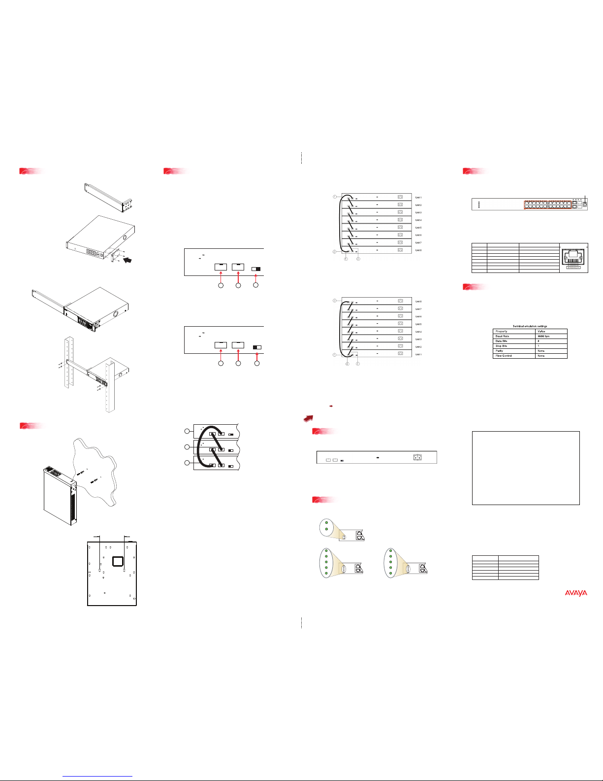
Setting IP parameters using the console port and CLI Quickstart
Console Port pin assignments
5c
Rack mounting singles - ERS 3510GT or ERS 3510GT-PWR+
To rack mount a single ERS 3510GT or ERS 3510GT-PWR+ switch:
Use the 3510-Single Rack Mount
Accessory Kit (AL3511003-E6) to
mount a single ERS 3510GT or
ERS 3510GT-PWR+ switch in a
standard 19” rack.
1. With the front of the
ERS 3510GT or
ERS 3510GT-PWR+
unit facing you, attach
the small bracket from
the optional kit to the
right side of the switch
using the flathead
screws provided.
To set IP parameters using the console port and CLI Quickstart, perform the
following tasks:
a. Connect a terminal to the console port of the switch.
Any terminal or PC with an appropriate terminal emulator can be used as
the management station. The Terminal emulation settings table below
lists the parameters that must be used with any terminal emulation software
used to connect to the switch.
To connect to the switch console port, you require
a console cable with an RJ-45 connector to match
the console port on the switch.
b. Set the terminal protocol on the terminal or terminal emulation program to
VT100 and VT100/ANSI.
c. Connect to the switch using the terminal or terminal emulation application.
d. The Avaya switch banner appears when you connect to the switch through
the Console port. Enter Ctrl+Y and type the following CLI commands:
• enable
• install
The ERS 3500 will set a default IP address of 192.168.1.1/24 by default if
the switch does not get its IP from another source.
The CLI Quickstart welcome screen helps you to enter the information
requested at each prompt.
CLI Quickstart welcome screen
#################################################################
Welcome to the ERS3500 setup utility.
You will be requested to provide the switch basic connectivity settings.
After entering the requested info, the configuration will be applied and
stored into the switch NVRAM.
Once the basic connectivity settings are applied, additional configuration
can be done using the available management interfaces.
Use Ctrl+C to abort the configuration at any time.
#################################################################
Please provide the in-band IP Address[192.168.10.6]:
Please provide the Default Gateway[0.0.0.0]:
Please provide the Read-Only Community String[**********]:
Please provide the Read-Write Community String[**********]:
Please provide the Quick Start VLAN <1-4094> [1]:
Please provide the in-band IPV6 Address/Prefix_length[::/0]:
Please provide the in-band IPV6 Default Gateway[::]:
Do you want to enable the DHCP server? y/n [n]:
#################################################################
Basic stack parameters have now been configured and saved.
#################################################################
You are now ready to use the ERS 3500 Series switch in your network
installation.
You can use the run ip office ACLI script to configure parameters according to
Avaya best practices for converged solutions. See the Getting Started guide
(NN47203-301).
Quick CLI Command guide:
boot - reboot the switch
boot default - reboot and use the factory default configurations
restore factory - default <-y> - reset the switch to factory default
configurations, use -y option for no prompts
For more related information, go to www.avaya.com/support
to download the following ERS 3500 guides:
Regulatory Information (NN47203-100)
Installation Job Aid (NN47203-303)
Product Release Notes (NN47203-400)
Getting Started (NN47203-301)
Documentation Roadmap (NN47203-101)
Name
RTS (Ready To Send)
DTR (Data Terminal Ready)
TXD (Transmit Data)
DCD (Carrier Detect)
GND (Ground)
RXD (Receive Data)
DSR (Data Set Ready)
CTS (Clear To Send)
Requirement
Optional - can swap or link with pin 8
Optional
Mandatory
Optional
Mandatory
Mandatory
Optional - can swap or link with pin1
Optional – can swap or link with pin1
RJ - 45 Jack
1
2
3
4
5
6
7
8
RJ - 45 8-Pin Female Jack
The console port is the RJ-45 port shown with a blue border outline on the
front of your ERS 3500 Series switch (note orientation). The port is labeled
console, and can be used to establish a management terminal connection to
the switch.
Check the front-panel LEDs as the device powers on to be sure the PWR LED is
lit. If not, check that the power cord is plugged in correctly.
Connect the AC power cord to the back of the switch or switches, and then plug
the other end of the cord into an AC power outlet. If powering up a stack of
switches, power on all switches together.
The Avaya Ethernet Routing Switch 3500 Series provides fail-safe stackability.
You can connect up to eight ERS 3500 Series devices in a stack to provide
uninterrupted connectivity for up to 192 to 208 ports. You can manage the stack
as a single unit.
To install/add a unit to a stack, you must change the default mode from
standalone to stacking mode and reboot the unit. See NN47203-303 for
more details.
Note: Stacking is not available for ERS 3510GT or ERS 3510GT-PWR+ switches.
Stacking is only supported with switches operating with Release 5.1 or
later software.
The Avaya Ethernet Routing Swith 3524GT, 3524GT-PWR+, 3526T, and
3526T-PWR+ back panel provides a Unit Select switch, Cascade Down port, and
Cascade Up port for stacking purposes as shown below:
Base Unit Select Switch – used to designate the base unit in a stack.
Cascade Down and Cascade Up ports – used to connect a switch to the
next unit in the stack through a cascade cable. Connect one end of the
Cascade Down cable to the Cascade Up port of the next switch in the stack
(shown in the three-switch stack connection block diagram below):
Base Unit Select switches
To create a stack connection, order the appropriate Avaya Ethernet Routing
Switch 3500 Series cascade cables to ensure fail-safe stacking. For stacking
three or more units (maximum eight units per stack), order the 46 cm, 1.5 m, or
3 m cables as applicable (see “Before You Start” – step 3 for Order Codes).
1. Ensure that all switches for the stack are rack mounted.
2. Slide the Unit Select switches on the back of the units to the appropriate
position, depending on whether they are a base unit or non-base unit:
• Base Unit (Unit 1) - Slide the Unit Select switch to the RIGHT
• Non-Base Unit (Units 2-8) - Slide the Unit Select switch to the LEFT
NOTE: The Base Unit Select switch defaults to be in the Non-Base position.
Only one switch in the stack must have the Base Unit Select switch set to the
Base position.
Because stack parameters are associated with the base unit, the physical stack
order depends on the base unit position and whether you configure the stack
cascade up (stack up) or cascade down (stack down). This designation depends
on the stack cabling arrangement.
IMPORTANT: Avaya recommends that you use a Cascade Down configuration.
Warning: You must use a power cord set approved for the 3500 Series switch and
the power receptacle type in your country.
The 3500 Series switches begin switching data after the switch is powered up and
has loaded the agent code software which is indicated by both the PWR and
Status LEDs being lit solid green.
You can use an RJ-45 to DB-9 cable to connect the switch console port to your
management terminal. Avaya recommends you use the Avaya RJ-45 Console
Cable part number: AL2011022-E6. Alternatively a DB-9 to RJ-45 adapter or
other suitable console cables can be used - the maximum length of a console
cable is 25 feet (8.3 meters). The following table describes the RJ-45 console
port pin-out information. You can use the pin-out information to verify or create
a console cable for use with your maintenance terminal.
Front Panel 3510GT and 3510GT-PWR+
Status
PWR
Status
PWR
Up/28
Down/27
Base
Front Panel 3524GT & 3524GT-PWR+ Front Panel 3524GT & 3524GT-PWR+
Status
PWR
Up/26
Down/25
Base
Mean Time Between Failure (MTBF) for ERS 3500 Series
ERS 3510 892,667
ERS 3510-PWR+ 673,542
ERS 3524 657,619
ERS 3524-PWR+ 336,357
ERS 3526 645,510
ERS 3526-PWR+ 332,778
Model Estimated MTBF Hours
NN47203-300-02.01
(700503194 Rev. 0.2)
© 2013 Avaya Inc.
WALL SECTION WITH
DRILLED HOLES
2X DRYWALL
ANCHORS
& SCREWS
3510GT AND\OR
3510GT-PWR+ CHASSIS
6
Wall Mounting - ERS 3510GT or ERS 3510GT-PWR+
To wall mount an ERS 3510GT or ERS 3510GT-PWR+ unit:
a. Drill two 4.5 mm diameter
holes (separated 108.5 mm
apart horizontally) in the
wall or surface where you
want to mount the unit.
Refer to the figure below.
b. Press fit the plastic body of conical
drywall anchors into each of the
drilled holes.
c. Install a tapping screen into each
anchor and fully set it to expand the
anchor into the wall or surface.
d. Back the screw out from the fully
seated position by 1.5 mm.
e. Slip the ERS 3510GT or ERS
3510GT-PWR+ chassis capture
slots over the exposed screw heads
to hang it from the wall or surface.
3510GT & 3510GT-PWR+ CAPTURE
SLOTS FOR WALL MOUNTING
108.5mm HOLE SEPARATION
ERS 3524GT/3524GT-PWR+ rear panel
ERS 3526T/3526T-PWR+ rear panel
2. With the front of the ERS 3510GT or ERS 3510GT-PWR+ unit facing you,
attach the long bracket from the optional kit to the left side of the switch
using the flathead screws provided.
3. Slide the switches into
the rack. Insert and
tighten the rack
mount screws.
Cascade Down - Recommended configuration
Cascade Up configuration
MODE
Standalone
Stacking
Port 25
Cascade DownCascade Up
Port 26
Unit Select
Base
MODE
Standalone
Stacking
Port 25
Cascade DownCascade Up
Port 26
Unit Select
Base
MODE
Standalone
Stacking
Port 25
Cascade DownCascade Up
Port 26
Unit Select
Base
3. Connect stacking cables as required for a Cascade Up (stack up) or Cascade
Down (stack down) configuration as shown below:
Console port
Configuring Stacking
MODE
Standalone
Stacking
Port 27
Cascade Down Cascade Up
Port 28
1
2
3
Unit Select
Base
MODE
Standalone
Stacking
Port 25
Cascade Down Cascade Up
Port 26
1
2
3
Unit Select
Base
1
2
3
1 – Base Unit
2 – Cascade/Stack Cable
3 – Cascade/Stack Cable (Used for return)
Unit 1
Unit 2
Unit 3
1 = Cascade down port
2 = Cascade up port
3 = Base Unit Select Switch - used to designate the Base
Unit in a stack. When set to the RIGHT position, this
unit acts as the Base Unit for the stack
1 = Cascade down port
2 = Cascade up port
3 = Base Unit Select Switch - used to designate the Base
Unit in a stack. When set to the RIGHT position, this
unit acts as the Base Unit for the stack
1 = Base unit
2 = Last unit
3 = Cascade/Stack Cable
4 = Cascade/Stack Cable (Return cable to make
stack resilient. Use longer stack cable if required.)
1 = Base unit
2 = Last unit
3 = Cascade/Stack Cable
4 = Cascade/Stack Cable (Return cable to make
stack resilient. Use longer stack cable if required.)
 Loading...