

Page 1

Enterprise Edge Networking
Operations Guide
1-800-4 NORTEL
www.nortelnetworks.com
© 1999 Nortel Networks
P0910464 Issue 01
Page 2

2
Enterprise Edge Attendant Console User Guide P0908544 Issue 01
Page 3

Contents
Chapter 1 Introducing Enterprise Edge 7
Routing and IP Services 7
System Software 8
Chapter 2 Using Enterprise Edge Unified Manager 9
Understanding Unified Manager 9
Changing the appearance of Unified Manager 12
Adjusting Unified Manager views 12
Navigating between views 13
Changing column order 14
Generating statistics 15
Menu descriptions 16
Chapter 3 Using Enterprise Edge Services 17
Enterprise Edge required parameters 17
Setting up an Enterprise Edge IP Address 18
Setting up web-based administration 19
Browser settings: 19
Logging on to Enterprise Edge 20
Logging off Enterprise Edge 21
Powering down the Enterprise Edge server 21
Rebooting the Enterprise Edge server 21
IP Routing 22
IP Routing Overview 22
Enterprise Edge IP routing specifics 23
IP Addressing Overview 23
Static Routing 24
Routing Information Protocol (RIP) 24
Enabling RIP on Network Interfaces 24
Packet Filtering 24
LAN-to-LAN Fast Path Routing 25
Dynamic Host Configuration Protocol (DHCP) 25
Automatic Configuration using a DHCP server 26
Guidelines for Using DHCP 26
Domain Name Service (DNS) 27
Guidelines for Using DNS 27
Web Caching/Proxy 28
Guidelines for Using Web Caching/Proxy 28
P0910464 Issue 01 Enterprise Edge Networking Operations Guide
Page 4

4 Contents
Simple Network Management Protocol (SNMP) 29
SNMP Overview 29
Guidelines for Using SNMP 29
Quality of Service 30
QoS overview 30
DiffServ Networks 31
Legacy Network 31
Admission Control 32
Packet Marking for DiffServ Networks 33
Port Range Setting for Legacy Networks 35
Relationship between the QoS Module and the VoIP QoS Monitor 36
Enterprise Edge QoS Restrictions and Defaults 36
LAN Connections 37
WAN Connections 37
WAN overview 37
Permanent WAN Connections 38
Frame Relay 38
PPP 38
Backup Up WAN Connection 39
Backup WAN Links 40
Chapter 4 Configuring Unified Manager Settings 41
Accessing system, resources, services and management settings on Unified
Manager 42
Configuring system settings 42
System name 43
System performance graphs and tables 46
System Fault Alarm Banner 47
System name, date and time 49
Chapter 5 Configuring Resources Settings 51
LAN 52
WAN primary links 56
WAN Primary Link Summary Parameters 58
WAN Primary Link Line Parameters 59
WAN Primary Link Frame Relay Parameters 61
WAN Primary Link PPP parameters 65
WAN Primary Link performance graphs and tables 66
WAN Backup Links 67
WAN Backup Link Summary Parameters 68
WAN Backup Link Parameters 69
WAN Backup Access Parameters 71
MSC 72
Telephony 73
Enterprise Edge Networking Operations Guide P0910464 Issue 01
Page 5

Chapter 6 Configuring Services Settings 75
DHCP 76
DHCP LAN 78
DNS 84
Routing 85
LAN Routing 86
WAN Routing 99
SNMP 101
SNMP Community List, Manager List, and Trap Community List 103
QoS 108
QoS performance graphs and tables 112
QoS filters 113
QoS Port Ranges 116
VoIP gateway 118
VoIP local and remote gateways 119
QoS monitor 124
QoS Monitor Mean Opinion Score 125
Web cache 126
NetLink Manager 127
Voice Record 129
Voice Record report settings 130
Voice Record report options 132
Voice Record market parameters 134
Voice Record PreFix 136
Voice Record Access/Suppress 137
TAPI Service Provider 138
Voice Service 140
Alarm Service 142
Voice Mail 143
Contents 5
Chapter 7 Configuring Management Settings 145
Configuring Management Settings 145
User Manager 145
Alarm Manager 148
Chapter 8 Diagnostics and Utilities 151
Saving System Settings 151
Downloading System Settings 152
Graphs and tables 154
Generating Statistics 154
Sample Rate 155
Error Messages 156
User Actions 156
Errors List 156
P0910464 Issue 01 Enterprise Edge Networking Operations Guide
Page 6

6 Contents
MIB II Information 161
Counters Shown at LAN and WAN Interface Levels 161
ICMP Counters 162
UDP Counters 163
TCP Counters 163
QoS Session Counters 163
QoS Best Effort Traffic Counters 163
QoS Dropped Packets Counter 164
QoS Graph Counters 164
QoS Best Effort Queue Counters 164
Appendix A: Troubleshooting 165
How to Get Help 165
Troubleshooting 165
Appendix B: Setting Up Remote Routers 167
Creating an Outbound Traffic Filter 167
Sample Criteria, Ranges, and Actions for UDP Filtering 168
Glossary 169
Index 177
Enterprise Edge Networking Operations Guide P0910464 Issue 01
Page 7

Introducing Enterprise Edge
Routing and IP Services
Enterprise Edge supports the following routing and IP Services:
• Routing Services
– IP Routing Protocol
– RAS Service and Dial In Capabilities for Management Purposes Only
– RIP
– Packet Filtering
• IP Services:
– DHCP
– DNS
– Web Caching
• VoIP (voice over IP) Service
1
VoIP is a term used in IP telephony for a set of facilities that manage voice
information delivery using Internet Protocol (IP). VoIP sends voice information
in digital form in discrete packets rather than in the traditional circuitcommitted protocols of the public switched telephone network (PSTN). A
major advantage of VoIP and Internet telephony is that it avoids ordinary telephone service tolls.
VoIP derives from the VoIP Forum which promotes the use of ITU-T H.323 as
the standard for sending voice (audio) and video using IP on the public Internet
and within intranets. The VoIP Forum also promotes the use of directory service
standards so that users can locate other users and the use of touch-tone signals
for automatic call distribution and voice mail.
In addition, VoIP uses the real-time protocol (RTP) over IP to help ensure that
packets get delivered in a timely way. Using public networks, it is currently
difficult to guarantee Quality of Service (QoS). Better service is possible with
private networks managed by an enterprise or by an Internet telephony service
provider (ITSP).
When using VoIP a business positions Enterprise Edge as a gateway. The
gateway receives packetized voice transmissions from users within the
company and then routes them to other parts of its intranet (local area or wide
area network) or sends them over the public switched telephone network.
P0910464 Issue 01 Enterprise Edge Networking Operations Guide
Page 8

8 Introducing Enterprise Edge
System Software
Enterprise Edge provides services to end-users in a small office environment. The
following services are managed through Enterprise Edge Unified Manager, a webbased user interface:
• IP Services
• VoIP Service
• Telephony Functions:
– PBX Call Processing
– Voice Mail
– Call Center Solution with Auto-Attendant
• Management Server Module
• QoS Module
Enterprise Edge Networking Operations Guide P0910464 Issue 01
Page 9
Using Enterprise Edge Unified Manager
This chapter introduces the major elements on the Enterprise Edge Unified
Manager graphical user interface including navigation and menu descriptions.
Unified Manager lets you view and change configuration settings for:
• IP Services
• VoIP Service
• Telephony Functions
• Management Server Module
• QoS Module
Understanding Unified Manager
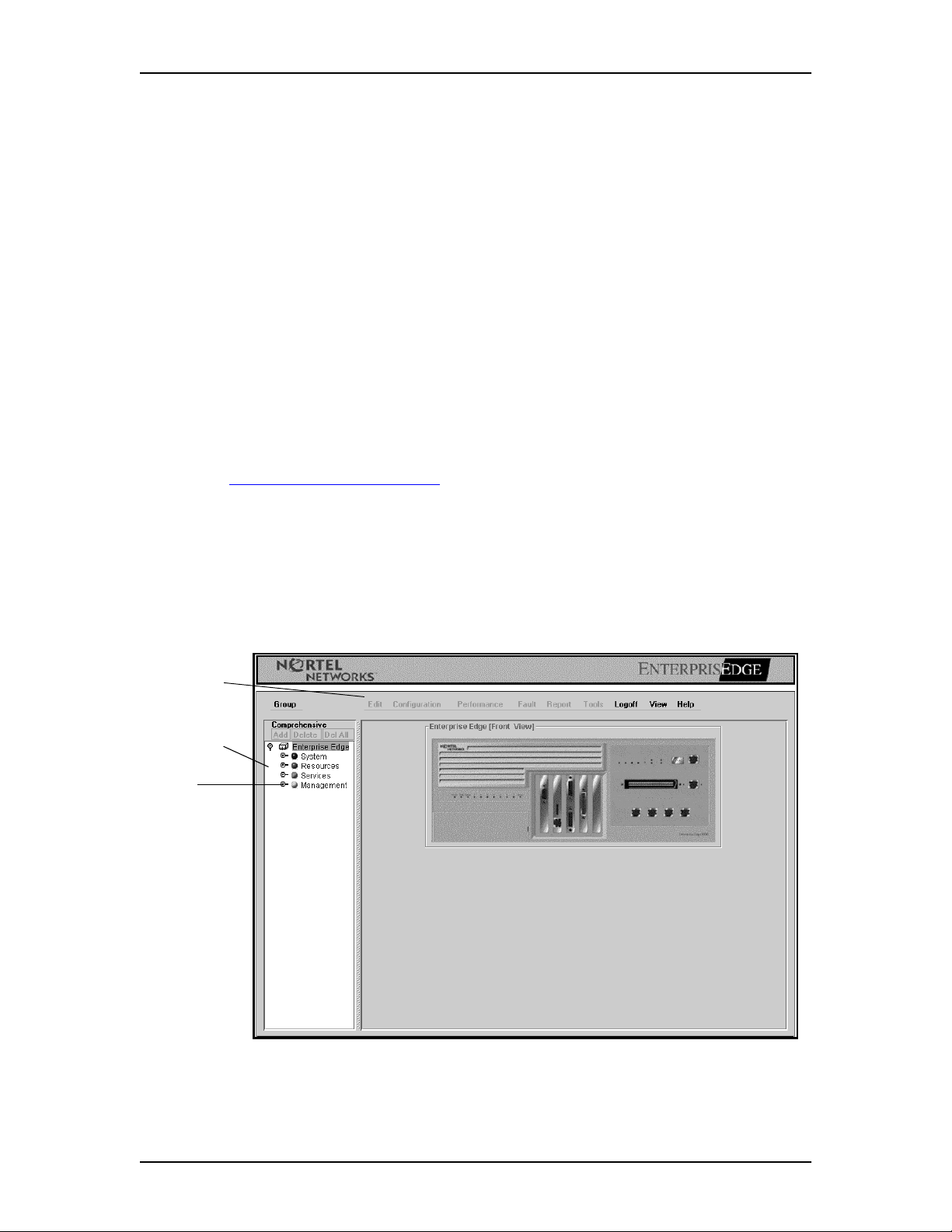
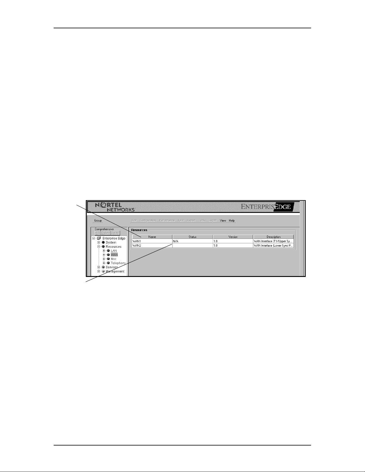
The Unified Manager main view shows the Unified Manager view including:
• The menu where users click commands
• The navigation tree used for navigating between views and configuration
screens
2
• The information panel view.
Unified Manager main view
menu
navigation
tree
keys
P0910464 Issue 01 Enterprise Edge Networking Operations Guide
Page 10

10 Using Enterprise Edge Unified Manager
As you navigate the menu tree shown in Unified Manager main view on page 9,
Unified Manager displays configuration screens. The screens contain settings that
you can edit to configure Enterprise Edge settings.
Enterprise Edge uses boxes and dialog boxes for configuring settings. Boxes let you
to edit and save data line by line. Each time you tab to the next line, the previous
line’s values are saved. See Unified Manager main view on page 9 for an example.
If a value is invalid, a beep sounds and an error message appears to alert you of the
error. The dialog box format allows you to enter text in boxes and save the settings
by clicking the Save button. See Unified Manager main view on page 9 for an
example.
The configuration screen contains:
• the title of the screen
• boxes
• scroll bars, when needed
• Save and Cancel buttons
To configure settings:
1. Click keys on the navigation tree or click commands on the menu.
The corresponding dialog box or screen appears.
2. Type the information in the appropriate box.
3. Click the Save button to save changes
or
click the Cancel button to close the configuration screen without saving any
changes.
Enterprise Edge Networking Operations Guide P0910464 Issue 01
Page 11
Using Enterprise Edge Unified Manager 11
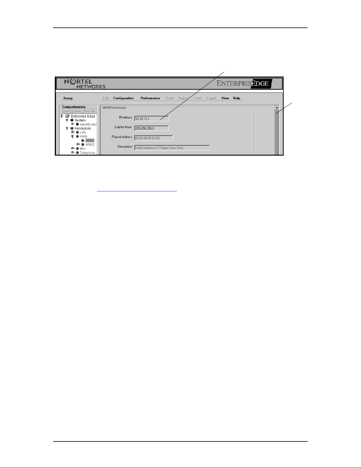
The following figure shows boxes and a scroll bar:
boxes
To make changes to boxes:
1. Click keys on the navigation tree until the configuration screen appears.
See Unified Manager main view on page 9.
scroll
bar
2. Type the updates in the appropriate boxes and follow the syntax that appears
next to the box.
If there is an error, a beep sounds and an error message appears.
3. Press the Tab key to move to the next box.
Pressing the Tab key saves changes in the current box and moves the cursor to
the next box..
Note: In some instances you must press the Tab key several times to move the
cursor to the next box.
P0910464 Issue 01 Enterprise Edge Networking Operations Guide
Page 12
12 Using Enterprise Edge Unified Manager
Changing the appearance of Unified Manager
You can choose from a Windows, Motif, or Metal look and feel.
To change the appearance of Unified Manager:
1. Click View and then click Windows, Motif, or Metal.
The view changes to a Windows, Motif, or default Metal appearance.
Changing look and feel
Adjusting Unified Manager views
The Enterprise Edge views are adjustable. You can resize Unified Manager and
configuration screens.
To resize a view or screens:
1. Move the pointer over any edge until it changes to a double-headed arrow.
2. Drag the edge of the screen to the desired location and release the mouse.
adjustable edges
adjustable edges
on navigation
tree
adjustable
columns
Note: Each time you exit Unified Manager, the display returns to the default
configuration.
Enterprise Edge Networking Operations Guide P0910464 Issue 01
Page 13
Using Enterprise Edge Unified Manager 13
Navigating between views
Choosing items in the navigation tree is the primary method for navigating the
Unified Manager menu.
The navigate between views:
1. Point to an item in the navigation tree and click the key to expand to the
desired view.
2. On the navigation tree, click the name of the item to display specific
information.
In this example, WAN is selected.
3. Click an item from the column to see information about it.
In this example, WAN1 is selected.
The resource information appears.
keys
click to
view
click to view
P0910464 Issue 01 Enterprise Edge Networking Operations Guide
Page 14
14 Using Enterprise Edge Unified Manager
Changing column order
You can change the order and size of data views in Unified Manager. You can
customize the view by resizing column widths or by reordering columns.
To change column order:
1. Click the column that you want to move.
2. Drag and drop the column to the appropriate location.
To change column width:
1. Move the pointer over any edge until it changes to a double-headed arrow.
2. Pull the column edge to the appropriate location.
column
heading
column edge
Enterprise Edge Networking Operations Guide P0910464 Issue 01
Page 15
Using Enterprise Edge Unified Manager 15
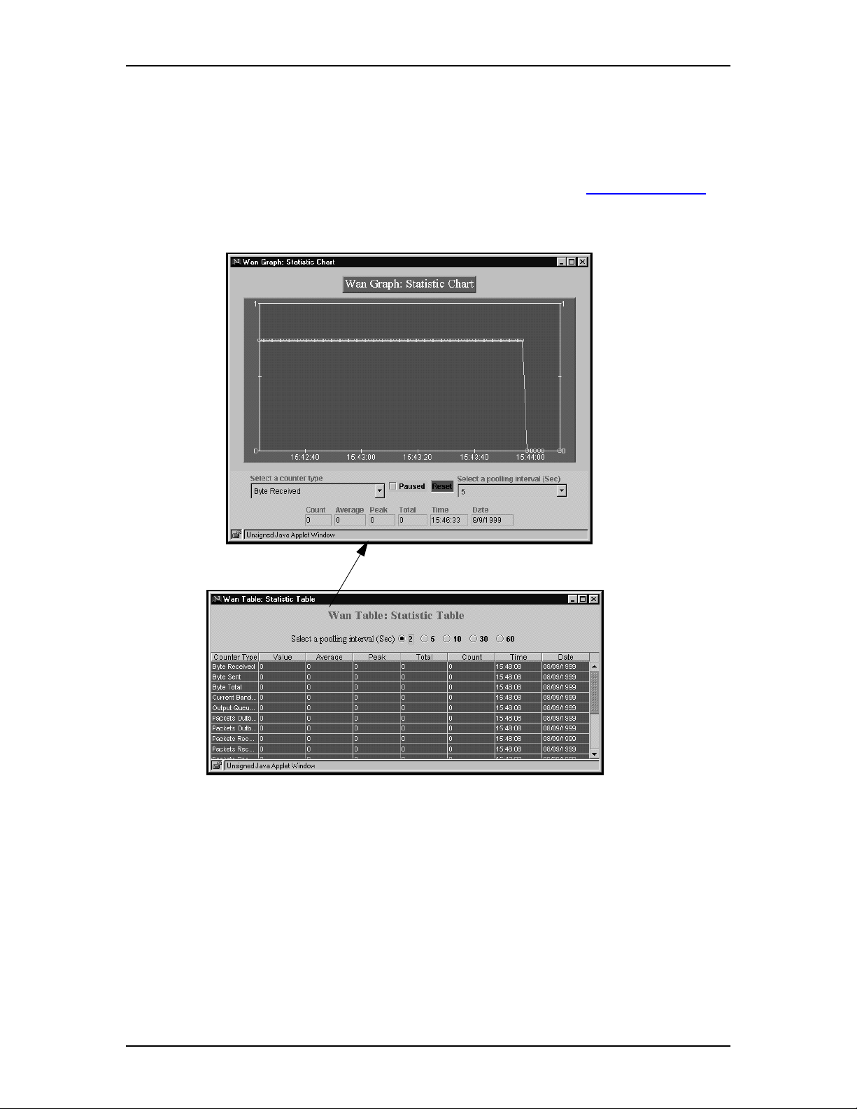
Generating statistics
Enterprise Edge provides statistical information on Enterprise Edge server
throughput and other performance-related information. The data is formatted in a
Statistical chart or Statistical table format.
For additional performance information and instructions, see Graphs and tables on
page 154.
Statistical chart
Statistical table
P0910464 Issue 01 Enterprise Edge Networking Operations Guide
Page 16

16 Using Enterprise Edge Unified Manager
Menu descriptions
You access Enterprise Edge functions using the menu. The menu is dynamic which
means that the menu commands change depending on the action a user takes.
Enterprise Edge menu
menu
Menu descriptions
Use To
Group View the system, resources, services, and management.
Edit Edit parameters.
Configuration Access configuration dialog boxes and screens
Performance Access performance graphs and tables.
Fault Access fault management settings.
Report Generate a report.
Tools Use Enterprise Edge tools.
Logoff Log off the Enterprise Edge server.
View Change the appearance from Windows, Motif or Sun Swing.
Help Access online help.
Enterprise Edge Networking Operations Guide P0910464 Issue 01
Page 17

Using Enterprise Edge Services
This chapter includes information on:
• Enterprise Edge required parameters
• Setting up an Enterprise Edge IP Address
• Setting up web-based administration
• Logging on to Enterprise Edge
• Logging off Enterprise Edge
• Powering down the Enterprise Edge server
• Rebooting the Enterprise Edge server
• IP routing
• Dynamic Host Configuration Protocol (DHCP)
• Domain Name Server (DNS) Service
• Web Caching/Proxy
3
• Simple Network Management Protocol (SNMP)
• Quality of Service (QoS)
• Using Traffic Filters
• Using Protocol Prioritization Queues
• LAN Connections
• WAN Connections
Enterprise Edge required parameters
The Enterprise Edge quick start module provides quick access to the parameters
necessary for the Enterprise Edge server to become active online. However, you
need to enter a minimum set of parameters within the quick start module. For more
information, see the Enterprise Edge Installation Guide.
Obtain the required parameter values from an Internet Service Provider (ISP) or
corporate network administrator.
Note: Nortel Networks recommends that after you powered on the Enterprise
Edge server and connect with either an RS-232 or an Ethernet port,
configure all the required parameters at the same time. After you configure
the parameters, reboot the Enterprise Edge server from either the console or
the graphical user interface (GUI).
P0910464 Issue 01 Enterprise Edge Networking Operations Guide
Page 18

18 Using Enterprise Edge Services
Users must enter the following parameters:
• Initial IP and mask for all network interfaces
• Primary (and optional secondary) DNS servers
• Default next hop router
• Fractional T1 channel numbers (if you are using fractional TI)
• System name
• WAN Link Protocol
• Frame Relay DLCI / CIR (if applicable)
• V.90 modem dial-up username and password (if applicable)
• V.90 modem dial-up phone number and optional alternate phone number (if
applicable)
The following table describes the Enterprise Edge server connectivity options.
Field Definition
HTTP You can launch your JAVA-enabled browser to connect to the Enterprise Edge
server IP address that connects to your PC. This displays the log in screen. See
the Enterprise Edge log on screen
TTY You can connect a dumb terminal to the console of the Enterprise Edge server
through an RS-232 cross-over cable, or, you can use Hyperterminal from Win95/
Win NT systems. Refer to the installation guide for console menus.
on page 20.
Setting up an Enterprise Edge IP Address
To manage the Enterprise Edge server using a web browser or a Telnet connection,
you must first set up the IP address. The Enterprise Edge server LAN interface is
shipped with default IP 10.10.10.1 and mask 255.255.255.0.
To set up the Enterprise Edge server initial IP address using a RS-232 port:
1. Turn on the Enterprise Edge server power switch.
2. Connect a PC or laptop computer to the Enterprise Edge server RS-232 port.
3. Start a hyper terminal on the PC or laptop computer.
4. Enter the LAN/WAN IP address and other parameters.
Enterprise Edge Networking Operations Guide P0910464 Issue 01
Page 19

To set up the Enterprise Edge server IP address using a LAN:
1. Turn on the Enterprise Edge server power switch.
2. Connect a laptop to the Enterprise Edge server by Ethernet (back-to-back by
using a crossover cable to avoid disturbing the corporate LAN).
3. Set your PC or laptop computer IP address to 10.10.10.2 with a mask
255.255.255.0.
4. Start a web browser on your laptop with a URL 10.10.10.1.
Setting up web-based administration
To establish web-based administration, a workstation needs to be set up as an
Enterprise Edge client with Internet Explorer 4.0 or greater and a JAVA Virtual
Machine (JVM) 5.0.0.2922 or greater installed.
To install JVM on a workstation, search the Microsoft information web page for
instructions.
Using Enterprise Edge Services 19
This minimum PC requirements are discussed in Enterprise Edge specifications.
Note: The ideal display for a monitor attached to Enterprise Edge is 1280 x 1024.
Browser settings:
Set your browser as follows:
Program Required Settings
Netscape Communicator 4.5
or greater
Internet Explorer 4.0 or
greater
Click Settings: Edit: Preferences
Category Advanced
set Enable Java: On
set Category: Cache
set Cached document comparison: Every Time
Choose Views: Internet Options Category: General: Temporary
Internet Files: Settings
click Check for newer versio ns of stored pages: Every vis it to t he
page
set Advanced Java VM
set Java JIT compiler enabled
Enterprise Edge OA&M allows multiple users to log on. If each user that logs on
attempts to configure the same or related subsystems, the most recent modification
remains in effect and overwrites changes by another administrator. Administrators
must be careful to not make any unintended changes.
P0910464 Issue 01 Enterprise Edge Networking Operations Guide
Page 20

20 Using Enterprise Edge Services
Nortel Networks recommends that only one administrator user account is
maintained in Enterprise Edge and access is closely cont rolled. Administrators must
coordinate changes to avoid unintended changes.
Note: Do not use proxy servers while configuring Enterprise Edge using WEB
OA&M. You must disable proxies and directly access Enterprise Edge. The
configuration procedures depend on the browser and version.
Logging on to Enterprise Edge
To log on to Enterprise Edge:
1. Open a web browser.
2. In the address, type the Enterprise Edge IP Address in a web browser.
For example: HTTP://10.10.10.1
3. Press the Enter key.
The Enterprise Edge log on screen appears
4. In the Login box, type your log on name.
The default log on name is supervisor.
5. In the Password box, type your password.
The default password is super.
6. Click the Configure button.
The Enterprise Edge Unified Manager software starts. Consult your system
administrator for appropriate information. Depending on your system, Unified
Manager software can take up to several minutes to initialize.
Enterprise Edge log on screen
Enterprise Edge Networking Operations Guide P0910464 Issue 01
Page 21

The log on screen includes these boxes:
Field Definition
Login The user name. The name can contain up to 50 case-sensitive alphanumeric
characters. The default log in name is supervisor.
Password The Enterprise Edge password. The password name can contain up to 12 case-
sensitive alphanumeric characters. The default password is super.
Configure lets you access Enterprise Edge configuration.
Upload lets you upload and apply Enterprise Edge settings and system settings.
Download lets you download and save Enterprise Edge settings and system settings.
Logging off Enterprise Edge
To log off Enterprise Edge:
1. Click the MSP icon on the left frame.
2. On the menu click Logoff and then click Logoff.
A message appears that asks you to confirm your request to log off.
Using Enterprise Edge Services 21
3. Click the Yes button to log off.
Powerin g d o wn the Enterpri s e E dge server
To power down the Enterprise Edge server:
1. From the menu of the console, quit Enterprise Edge.
2. Remove the power connection.
Rebooting the Enterprise Edge server
To reboot the Enterprise Edge server:
1. Click Logoff and then click Reboot.
A message appears that asks you to confirm your request to reboot.
2. Click the Yes button to reboot.
P0910464 Issue 01 Enterprise Edge Networking Operations Guide
Page 22

22 Using Enterprise Edge Services
IP Routing
This section includes information on:
• IP Routing Overview
• Enterprise Edge IP routing specifics
• IP addressing overview
• Static routing
• Routing Information Protocol (RIP)
• Packet Filtering
– source address
– destination address
– IP Protocol ID
– TCP Port
– UDP Port
– ICMP Type
– ICMP Code
• LAN to WAN routing
– managing traffic using Interrupt Modulation
• LAN to LAN routing
– Fast Path Routing
IP Routing Overview
The Internet Protocol (IP) is the protocol used on the Internet to send data is sent
from one computer to another. Each computer on the Internet, called a "host", has
at least one address that id entifies it from all other computers o n the Internet. When
you send or receive data (for example, an e-mail or a web page), the message gets
divided into units called packets. Each of these packets contains both the sender's
Internet address and the receiver's Internet address.
A packet is first sent to a router that understands reads the destination address and
forwards the packet to an adjacent router that reads the destination address.This
routing process continues across the Internet until one router recognizes the packet
as belonging to a computer in its immediate neighborhood or domain. That router
forwards the packet to the computer whose address is specified.
Because a message is divided into a number of packets, each packet can, if
necessary, be sent by a different route across the Internet. Packets can arrive in a
different order than the order they are sent. Another protocol, the Transmission
Control Protocol (TCP) to put the packets in the right order.
Enterprise Edge Networking Operations Guide P0910464 Issue 01
Page 23

Using Enterprise Edge Services 23
IP is a connectionless protocol, which means that there is no established connection
between the end points that communicate. Each packet that travels through the
Internet is treated as an independent unit of data without any relation to another unit
of data. The packets get put in the right order because TCP, the connection-oriented
protocol, keeps track of the packet sequence in a message. In the Open Systems
Interconnection (OSI) communication model, IP is in layer 3, the Networking
Layer.
Enterprise Edge IP routing specifics
Using Enterprise Edge Unified Manager, you can perform the following routing
configuration options:
• Add or delete the interfaces to routing protocols
• Configure routing protocol options
• Add and delete static routes
• Add or delete filters
• Set filter actions
For instructions on configuring routing options, see Routing on page 85.
The followings table shows the Enterprise Edge IP routing protocols and the
precedence order when conflict or redundant routes occur.
Precedence IP Routing Protocols
1. Static Routing
2. SNMP
3. RIP v1 and v2
IP Addressing Overview
IP addresses follow the format nnn.nnn.nnn.nnn, where nn is a number between 0
and 255. For example, 192.123.4.56 or 10.1.1.1. IP addresses enable computers to
communicate to each other. Both servers and workstations on a network must have
IP addresses. There are two types of IP addresses:
Dynamic – A dynamic IP address changes. Dynamic IP addresses are assigned
to computers by an IP address server as the computer needs it. Usually there is
a particular range or scope of IP addresses that your network uses. With
dynamic IP addressing, a computer can have a different IP address every time
it connects to the network. Other devices need to know the computer’s IP
address so that they can communicate with it. The IP address server manages
the assignment of IP addresses to the client workstations.
Static – A static or fixed IP address never changes. It is assigned to a computer
permanently. The computer has the same IP address every time it connects to
the network and is known to other devices on the network by that IP address.
P0910464 Issue 01 Enterprise Edge Networking Operations Guide
Page 24

24 Using Enterprise Edge Services
Static Routing
Enterprise Edge users can add static routes to the IP routing table. These static
routes take precedence over those routes chosen by routing protocols, such as RIP.
To add a static route, see Static Route on page 94.
Note: Ensure that users do not add a static route for default route 0.0.0.0 with mask
0.0.0.0. Enterprise Edge’s Net Link Manager automatically creates a default
route and adjusts it according to link status unless router or Net Link
Manager are running.
Routing Information Protocol (RIP)
RIP is a widely-used protocol for managing routing information in a self-contained
network such as a corporate intranet. RIP is classified by the Internet Engineering
Task Force (IETF) as one of several internal gateway protocols (IGPs).
A RIP router sends full updates, which list all the other hosts it knows about, to its
closest neighbor host every 30 seconds. The neighbor host sends the information to
its next neighbor, until all the hosts in the network know the routing paths, a state
known as network convergence. RIP uses a hop count to determine network
distance. Each host with a router in the network uses the routing table information
to determine the next host for the packet, until a specified destination is reached.
Enabling RIP on Network Interfaces
To run RIP on one or more network interfaces, go to the specific interface under
router and enable RIP. After you enable RIP for an interface, you do not have to
reboot the Enterprise Edge server for the changes to take effect.
Packet Filtering
A packet is a unit of data routed between an origin and a destination on the Internet
or on any other packet-switched network. When any file such as an e-mail message,
HTML file, GIF file or URL request, is sent on the Internet, the IP layer divides the
file into packets of an efficient size for routing. Each of these packets is numbered
and includes the Internet address of the destination.
Enterprise Edge supports basic (or stateless) packet filtering for IP. You can
configure the filter to pass only the packets from the routes they list, or to pass
everything except the packets for the routes they list.
Each route in the list can be any combination of the following packet filtering
features. By default, no packet filer is configured.
Enterprise Edge Networking Operations Guide P0910464 Issue 01
Page 25

Using Enterprise Edge Services 25
Enterprise Edge supports the following packet filtering features for IP:
Packet Filter Feature Comments
Source Address the source address field of the packet to be filtered.
Source Mask the source address mask of the packet to be filtered.
Destination Address the destination address field of the packet to be filtered.
Destination Mask the destination address mask of the packet to be filtered.
Protocol the protocol type of the packet to be filtered.
Source Port the source port of the packet to be filtered. This field applies
only if protocol value is TCP or UDP.
Destination Port the destination port of the packet to be filtered. This field
applies only if protocol value is TCP or UDP.
ICMP Type the ICMP type field of the packet to be filtered. This field
applies only if protocol value is ICMP.
ICMP Code the ICMP type field of the packet to be filtered. This field
applies only if protocol value is ICMP.
Note: When you set filters, you must forward packets going to the RPC port (port
135 TCP or UDP) for correct Unified Manager operation.
LAN-to-LAN Fast Path Routing
Enterprise Edge provides an optional second 10/100 LAN interface. If the second
LAN interface is used, Enterprise Edge uses optimized software for high
performance routing. This includes an innovative design that speeds up the
performance for LAN-to-LAN routing by over three times the rate that is normally
achieved using traditional software architecture.
Dynamic Host Configuration Protocol (DHCP)
DHCP (Dynamic Host Configuration Protocol) is a protocol that lets network
administrators manage and automate the assignment of Internet Protocol (IP)
addresses in an organization's network. Using the Internet's set of protocols (TCP/
IP), each machine that can connect to the Internet needs a unique IP address. If an
organization sets up its computer users with a connection to the Internet, an IP
address must be assigned to each machine.
Without DHCP, the IP address must be entered manually at each computer. If
computers move to another location in another part of the network, a new IP address
must be entered. DHCP lets a network administrator supervise and distribute IP
addresses from a central point and automatically sends a new IP address if a
computer connects to a different place in the network.
You can set up Enterprise Edge to be your LAN’s DHCP server and let it assign IP
addresses to the workstations on your LAN as they need them. This is the
recommended configuration.
P0910464 Issue 01 Enterprise Edge Networking Operations Guide
Page 26

26 Using Enterprise Edge Services
If you set up the Enterprise Edge server as a DHCP server, you must let all of your
workstations know that they will have their new IP addresses assigned by
Enterprise Edge. To do this, you may need to change the configuration of each
workstation individually.
If you already have a DHCP server, you must let it know that the Enterprise Edge
server is their gateway and DNS proxy for the workstations.
Your Enterprise Edge server can function as a DHCP server. You can use this
feature if you do not want to administer static IP addresses for every workstation on
your network. You can configure Enterprise Edge to assign IP addresses
dynamically.
Automatic Configuration using a DHCP server
To configure the DHCP server, you need to create a particular range (or scope) for
each LAN interface in Enterprise Edge and allocate a block of IP addresses for that
scope. The Enterprise Edge Auto-Configure system automatically creates a scope
using parameters inherited from the LAN interface.
Guidelines for Using DHCP
Since many default DHCP parameters are inherited from LAN interface
parameters, configure LAN interfaces before configuring DHCP.
If you are modifying the DHCP configuration on Enterprise Edge, follow the same
guidelines of your organization. In particular, you can perform one or more of the
tasks listed below to ensure proper operation of the networked system:
1. If a change in the DHCP configuration resulted in the change of ‘Router’ and
‘Subnet mask’ options in a scope, users must do one of the following to
ensure basic operation:
• Execute ipconfig /release and ipconfig /renew on each of the workstations.
For Windows 95 and Windows 98, use its equivalent, winipcfg.
• For clients that do not support ipconfig and winipcfg, reboot is required to
renew their IP addresses.
2. If change in DNS server or DNS name options happens, users need to repeat
the tasks in step 1 to ensure proper connectivity with the organization.
3. Always schedule a down time associated with these changes.
4. Nortel Networks recommends that you reboot Enterprise Edge to initialize
changes.
Using Enterprise Edge, you can define a DHCP scope for each LAN interface.
DHCP server parameters are divided into two categories: global and scope specific.
Global parameters apply to all scopes. Specific parameters apply to a specific
scope.
Enterprise Edge Networking Operations Guide P0910464 Issue 01
Page 27

Domain Name Service (DNS)
The domain name service (DNS) is the system within the Internet t hat maps names
of objects, usually host names, into IP numbers or other resource record values. The
name space of the Internet is divided into domains. The responsibility for managing
names in each domain is usually delegated to systems in each domain.
Enterprise Edge functions as both a gateway to the Internet and as a DNS proxy:
• Gateway: a system that links two different types of networks and enables them
to communicate with each other. Enterprise Edge is the gateway that links your
company’s network to the Intranet or Internet. Depending on your
configuration, you can let your workstations know that Enterprise Edge is your
Internet gateway.
Note:If your PC is a DHCP client under Enterprise Edge, you do not have to do
this.
• DNS Proxy – A Domain Name Service (DNS) proxy translates alphabetic
domain names into computer-readable IP addresses. For example, the domain
name www.nortelnetworks.com for the Nortel Networks web site can translate
to the IP address 192.177.5.18. After a domain name is translated into an IP
address, the workstations on your network can communicate with the web site.
Depending on the configuration of your system, you can let your workstations
know that Enterprise Edge is the DNS proxy.
Using Enterprise Edge Services 27
When Enterprise Edge receives DNS requests from clients, it first checks its local
cache for name entries and records. If found locally, Enterprise Edge immediately
responds to clients. Otherwise, Enterprise Edge creates a new DNS request to the
remote Primary or Secondary DNS servers on behalf of the client. If the remote
DNS server responds with the requested records, they are forwarded to clients and
cached in Enterprise Edge.
Note: If your PC is a DHCP client under Enterprise Edge, you do not have to let
your workstations know that Enterprise Edge is your DNS server.
Guidelines for Using DNS
Consider the following guidelines when using DNS:
• If the Enterprise Edge DNS service is enabled, make sure that clients always use
Enterprise Edge as their DNS server.
• When it is disabled, set the DNS Server field in DHCP configuration to the
remote DNS server IP address. If DHCP service is also disabled in Enterprise
Edge, tell all clients to set the DNS server in their IP configuration to the remote
DNS server.
• The DNS proxy carries security features because it keeps all of the internal IP
addresses from external web servers.
• You are required to fill in the remote Primary DNS server IP addres s. See DNS
on page 84 for instructions.
P0910464 Issue 01 Enterprise Edge Networking Operations Guide
Page 28

28 Using Enterprise Edge Services
Web Caching/Proxy
When you use Enterprise Edge as a web proxy, Enterprise Edge can store or
cache information downloaded from the Internet. A proxy is a server that acts on
behalf of another. Web caching allows LAN workstations to share common
information downloaded from the Internet.
Data is usually cached on individual workstations. Each time a workstation on the
LAN requests information from the Internet, the individual’s request is sent to the
Internet, and the information is returned to their workstation. If multiple LAN
workstations request common data, a web cache on the network reduces download
time from the Internet.
With Enterprise Edge configured as a web proxy with web caching:
• LAN workstations have shorter download times.
• Previously downloaded information is stored for future use by all workstations
on the LAN.
• Enterprise Edge retrieves information from the Internet only if it is not already
cached or if the cached file is out of date compared to the information on the
Internet.
• Cookie blocking protects users’ privacy.
You can configure the web caching settings through your web browser.
The web proxy also provides security features similarly to the DNS proxy because
it hides all of the internal browsers’ IP addresses from external web servers.
External web servers see Enterprise Edge’s IP address.
Guidelines for Using Web Caching/Proxy
The Enterprise Edge web proxy uses a web server for running in HTTP-Proxy
mode.
Consider the following guidelines when using web caching/proxy:
• A web server installed in Enterprise Edge can not be used as a general purpose
HTTP server. It is only used by the Enterprise Edge web-based management
client and web-cache services.
• If users need to run their web sites, they need to run the HTTP Server on another
system and make its IP address known to Enterprise Edge.
To set the web server as the web cache/proxy, refer to Web cache on page 126.
Enterprise Edge Networking Operations Guide P0910464 Issue 01
Page 29

Simple Network Management Protocol (SNMP)
This section includes information on:
• SNMP Overview
• Guideline for Using SNMP
SNMP Overview
Simple Network Management Protocol (SNMP) is the protocol that governs
network management and the monitoring of network devices and their functions.
Guidelines for Using SNMP
Consider the following guidelines when using SNMP:
• You can set read-only and read-write community names.
• You can set a list of permitted managers. When set, the agent responds to
requests from SNMP managers from only those IP hosts.
• An empty list of permitted managers implies that agent responds to requests
from anyone.
Using Enterprise Edge Services 29
• You can set trap communities. Each trap entry identifies the community name
that must be used and the manager addresses.
• You can enable or disable sending authentication traps.
• You can enable or disable the SNMP agent.
• At present, SNMP supports only MIB-II (RFC 1213) MIBs.
P0910464 Issue 01 Enterprise Edge Networking Operations Guide
Page 30

30 Using Enterprise Edge Services
Quality of Service
This section includes information on:
• QoS overview
• DiffServ networks
• Legacy networks
• Admission control
• Packet marking for DiffServ networks
• Port range setting for legacy networks
• Relationship between the QoS Module and the VoIP QoS monitor
• Enterprise Edge QoS restrictions and defaults
QoS overview
On the Internet, Quality of Service (QoS) is the methodology that transmission
rates, error rates, and other characteristics can be measured, improved, and, to some
extent, guaranteed in advance. QoS is of concern for the continuous transmission of
high-bandwidth voice and video multimedia informati on. Transmitting this content
dependably is difficult in public networks using ordinary “best effort” protocols.
Real-time applications that include voice and video are time-sensitive. Delivering
voice and video over the Internet requires bounded packet delay and jitter.
Differentiated Services (DiffServ) is a QoS framework standardized by IETF that
focuses on DiffServ standards for real-time and mission critical applications. The
DiffServ standards are evolving and vendors are starting to develop network
devices that support DiffServ.
The purpose of the Enterprise Edge QoS module is to prioritize IP traffic and to
provide an acceptable quality of service to delay and jitter sensitive applications
such as audio and video as well as mission critical applications.
The Enterprise Edge QoS module primarily serves two purposes:
• In a DiffServ network, it acts as an edge device and performs the packet
classification, marking, and prioritization.
• In a non-DiffServ or legacy network, it manages the WAN link to make sure
premium voice (and optional video) packets get high priority when crossing the
slow WAN link in both directions.
Enterprise Edge Networking Operations Guide P0910464 Issue 01
Page 31

Using Enterprise Edge Services 31
DiffServ Networks
For DiffServ networks, Enterprise Edge:
• Intercepts all H.323 traffic
• Identifies call setup packet
• Performs admission control based on the WAN link usage
• Marks the packets as premium once admitted
Enterprise Edge implements the DiffServ queuing model that includes a premium
queue and eight best-effort queues. The premium queue has a stricter high priority
than the best-effort queues. The eight best-effort queues are scheduled by a
weighted-fair-queuing (WFQ) algorithm. Since best-effort traffic is not shaped and
does not go through the admission control process, the WFQ is needed to avoid
starvation of low priority packets.
Currently, H.323 traffic is allowed to get into the premium queue. Users can allow
other traffic to be premium by setting up priority filters on the web-based GUI using
the following filter criteria:
• Source IP address (with mask)
• Destination IP address (with mask)
• IP protocol ID (e.g. TCP, UDP, or ICMP)
• Source port range
• Destination port range
• Incoming TOS field
Note: There is no traffic shaping mechanism implemented in this version. Be
cautious when setting up premium priority filters. If the traffic is high
volume and with high bursts, it may impact VoIP quality. Unless necessary,
Nortel Networks recommends that you allocate traffic to the high priority
best-effort queues instead of the premium queue.
Legacy Network
In a legacy network, Enterprise Edge assumes that network devices, such as routers
and switches, do not recognize the IP header TOS field (as defined by DiffServ) and
do not perform the corresponding priority processing. However, most of the current
installed routers, including those from Cisco and Nortel Networks, allow
administrators to set up priorities by IP addresses, port numbers or protocol types,
which is similar to the priority filters described above.
Note: This information is specific to H.323 traffic in legacy networks.
In this environment, Enterprise Edge allows H.323 voice (and optional video)
packets to travel across the WAN link with high priority in both directions using
existing router features.
P0910464 Issue 01 Enterprise Edge Networking Operations Guide
Page 32

32 Using Enterprise Edge Services
An administrator needs to reserve a block of UDP port numbers and configure them
as high priority in both Enterprise Edge and the remote router at the other end of the
WAN link. Enterprise Edge forces all of the admitted H.323 streams to fall into the
reserved port range by using a proprietary technique so that these H.323 voice
(video) packets can get high priority. This is completely transparent to the end
H.323 terminals.
See Appendix B: Setting Up Remote Routers on page 167 for additional
information on setting UDP port ranges for remote routers.
Note: If an administrator configures all routers in their corporate network
with the same reserved port numbers (both in and out), admitted H.323
streams can get end-to-end high priority. However, routers connected
to WAN links are more critical because they are typically the
bottlenecks.
You can set up best-effort traffic priorities through the web-based Unified Manager
by using the following filter criteria:
• Source IP address (with mask)
• Destination IP address (with mask)
• IP protocol ID (e.g. TCP, UDP, or ICMP)
• Source port range
• Destination port range
• Incoming TOS field
There are a total of 8 priority classes for best-effort traffic in Enterprise Edge. By
default, all best-effort traffic is sent to Class 5 (queue 5), with Class 1 the highest
and Class 8 the lowest in priority.
Admission Control
Enterprise Edge allows users to set a certain percentage of the WAN bandwidth for
premium traffic. This traffic takes strict priority over best-effort traffic. In this
version, H.323 (VoIP) flows need to pass the admission control process to be
treated as premium traffic.
For admission control, Enterprise Edge uses the WAN Premium Bandwidth
parameter. Specifically, for each H.323 flow, QoS performs admission control
using the negotiated coding algorithm. A flow is admitted a s a premium flow if the
current total WAN premium usage plus the new flow is lower than the allocated
WAN premium bandwidth.
Otherwise, the flow is rejected and he flow is still delivered as best-effort traffic.
Enterprise Edge Networking Operations Guide P0910464 Issue 01
Page 33

Using Enterprise Edge Services 33
As a reference point: for a typical G.729 codec, each VoIP flow requires the
following WAN bandwidth, depending on the codec sample rate:
G.729 Sample Rate
30 ms
No
Compression
Data
Compression
RTP Hdr Comp. 5.8 k 6.8 k 9.6 k
10.6 k 14 k 24 k
8 k 10 k 16 k
Sample Rate
20 ms
Sample Rate
10 ms
Note: The calculation is based on a full-duplex WAN link with HDLC overhead
and VoIP with silence suppression.
Nortel Networks recommends that for slow WAN links, such as a 56K leased line
or ISDN, H.323 video is not configured as premium traffic.
Packet Marking for DiffServ Networks
Enterprise Edge classifies traffic and marks packets by setting the IP header type of
service (TOS) field. By default, the following items are classified as premium
traffic:
• All VoIP flows
• RIP packets: routing packets are periodically exchanged between Enterprise
Edge and remote routers. These packets need higher priority than regular
packets to ensure that the routing protocol is working properly.
• ICMP packets: Enterprise Edge Net Link Manager uses the ‘ping’ command to
decide whether the primary WAN link is active or inactive. These packets are
not delayed by regular packets.
• UDP Port 5000 packets – Enterprise Edge VoIP QoS Monitor uses port 5000 in
a proprietary protocol to monitor the IP network delay and jitter. Since
Enterprise Edge assigns VoIP packets to the premium queue, it also gives these
monitor packets high traveling priority.
• Admitted RTP/RTCP packets.
In Enterprise Edge, there are two places a user can set up a TOS field in an IP
header:
TOS-for-Premium-Traffic – this field sets TOS bits for premium packets for
DiffServ networks. If this field is ignored, Enterprise Edge uses a default value
of 0xB8.
TOS-for-Priority-Filters– this field sets TOS for those packets matching a
specific priority filter.
Note: You can specify packets matched to a filter to go Priority Queue 0 – 8. The
Queue 0 is for premium packets, and Queue 1 – 8 correspond to best-effort
priority classes 1 – 8.
P0910464 Issue 01 Enterprise Edge Networking Operations Guide
Page 34

34 Using Enterprise Edge Services
If you specify Queue 0 and a TOS bits for a filter, then this TOS takes
precedence over the TOS set for premium traffic for all packets tha t match this
filter.
The default TOS for all best-effort packets is 0x00, and the default queue for
best-effort packets is Queue 5.
WARNING
Premium flows that are specified by priority are not admission controlled. Unless
you know the behavioral characteristics of a flow, do not specify flows as premium.
Instead, you can specify them as the highest B-E traffic.
Consider the following guidelines when you set up priority filters
• The fewer the conditions to check for, the fewer CPU cycles are consumed.
Filter processing is faster if fewer conditions are specified, without
compromising the precision in selection.
• If you don’t need the value of a particular criterion, such as source port number,
don’t set a corresponding value for the filter.
• When you specify the layer 3 sub-protocols, use the port number/IP address
combinations and avoid specifying the protocol field. Nortel Networks
recommends that you specify a protocol field only if you manage an unusual
condition in your network. This reduces the consumption of CPU cycles.
• Users can configure the precedence of the filters. Packets are matched against
each filter sequentially until a match is found. Pay attention when specifying the
precedence of filters. Placing ‘popular’ filters ahead of ‘unpopular’ filters can
significantly speed up the processing.
Enterprise Edge Networking Operations Guide P0910464 Issue 01
Page 35

Using Enterprise Edge Services 35
Port Range Setting for Legacy Networks
Enterprise Edge uses UDP port ranges to provide high priority to VoIP packets in
existing legacy IP networks. These same port ranges must be reserved and set to
high priority on all routers that an administrator expects to have QoS support.
Reserving port ranges is not required for DiffServ networks.
You can select any port ranges that are not used by well-known protocols or
applications.
Each H.323 or VoIP RTP flow uses two ports. The total number of UDP port
numbers to be reserved depends on how many concurrent RTP flows are expected
to cross a router interface. In general:
• Backbone routers reserve more ports than edge routers.
• Edge routers’ port ranges are a subset of the backbone router port ranges.
• Add UPP 5000 to high priority.
• Enterprise Edge’s port ranges are a subset of the remote router’s port ranges.
• You must reserve two ports for each voice call you expect to carry over the
WAN. You need two ports for each video session if it is given premium
treatment.
• You can reserve multiple discontinuous ranges. Nortel Networks requires each
range meet the following conditions:
- Each range must start with an even number.
- There must be an even number of ports in a range.
See Appendix B: Setting Up Remote Routers on page 167 for additional
information on setting UDP port ranges for remote routers.
P0910464 Issue 01 Enterprise Edge Networking Operations Guide
Page 36

36 Using Enterprise Edge Services
Relationship between the QoS Module and the VoIP QoS Monitor
The VoIP gateway in Enterprise Edge includes a Quality-of-Service Monitor
(QMON) that periodically monitors the delay and jitter of IP networks between two
peer gateways by using a proprietary protocol. These monitoring packets are
delivered at UDP port 5000.
The main objective of the QMON is to allow new VoIP calls to fa ll-ba ck to PSTN
if the IP network is detected as “bad”.
The QoS module discussed here complements QMON. While QMON passively
monitors the IP network, the QoS module actively improves the IP network by
giving VoIP packets higher priority to travel so that the chance for QMON to detect
“bad” is reduced.
Note: For a VoIP call, if a packet passes QMON but fails the QoS admission
control, it is delivered over IP but only as a best-effort flow. There is no fall
back to PSTN if a packet has passes QMON checking.
QMON packets travel at the same priority as VoIP packets or at higher priority than
normal IP packets. If VoIP packets travel at a premium level but QMON packets
travel at normal best-effort level, it is possible for QMON to report the IP network
as “bad” and start to PSTN fall-back, but the actual delay and jitter for VoIP packets
are still “good”, since VoIP packets have a higher priority. To avoid this add UDP
port 5000 to the high priority queue in all routers.
Enterprise Edge QoS Restrictions and Defaults
Enterprise Edge QoS includes the following restrictions and defaults:
• By default, the general bulk of traffic (not defined by priority filters) is routed
to best-effort Queue 5 (with Queue 1 the highest priority and Queue 8 the
lowest). An administrator can define four classes of traffic above the generic
traffic and three classes below it.
• A maximum of 31 priority filters for best-effort traffic can be created.
• The QoS module can be optionally turned ON or OFF. The default setting is on.
• The predetermined WAN bandwidth is always available to VoIP gateway
channels. That is, VoIP gateway calls are always admitted. The remaining
WAN premium bandwidth can be used by other H.323 streams, such as
Microsoft NetMeeting. If there is no VoIP gateway traffic, their WAN
bandwidth can be used only by best-effort traffic, not other premium traffic (for
example, Netmeeting). Enterprise Edge does not support preemption of
admitted premium streams.
• Currently packet prioritizing and priority filters apply only to outbound traffic
for specified interfaces. Inbound traffic is treated on a first in first out (FIFO)
priority.
• The maximum port numbers a user can reserve for premium traffic is 256.
Enterprise Edge Networking Operations Guide P0910464 Issue 01
Page 37

LAN Connections
The Enterprise Edge Ethernet / 802.3 interface supports IEEE 802.3 Ethernet frame
format. The Ethernet interface uses Carrier Sense Multiple Access with Collision
Detection (CSMA/CD) to manage the access to the physical media.
Enterprise Edge Ethernet interface supports the following features:
• 100 BASE – TX with RJ-45 connector
• 10 / 100 Auto Sense
• Full Duplex support
• Fast LAN-LAN routing
WAN Connections
This section includes information on:
• WAN overview
• Permanent WAN connections:
Using Enterprise Edge Services 37
– Frame Relay
– PPP
WAN overview
A WAN (wide area network) is a geographically dispersed data communication
network. The term WAN distinguishes a broader data communication structure
from a local area network (LAN). A WAN can be privately owned or rented, but
usually connotes the inclusion of public (shared user) networks.
Enterprise Edge includes two primary WAN links (WAN1, WAN2) and a backup
WAN dial up link (WAN3).
• The Primary WAN link is always a permanent link and it is a dedicated network
adapter. The primary link runs either Frame Relay or the PPP protocol at the
link layer.
The Enterprise Edge primary WAN connection is through a two-port card.
These two ports can be independently configured to run Frame Relay or PPP.
The card includes one serial sync port and one T1 port.
• The backup WAN link is always configured as dial-on-demand network adapter
by the router. The backup Wan link runs PPP only. Enterprise Edge provides
backup WAN connection through a V.90 modem.
The primary and backup link management is performed from Enterprise Edge.
There is a Net Link Manager running in Enterprise Edge that monitors the
primary link status and it starts the backup link when a break in primary link is
detected. Similarly, the backup link is automatically terminated when the
primary link becomes active.
P0910464 Issue 01 Enterprise Edge Networking Operations Guide
Page 38

38 Using Enterprise Edge Services
Note: Net Link Manager can back up only one link, even though there are two
primary links. Net Link Manager backs up the link whose next hop address
is given to it.
• Net Link Manager manages the default route in Enterprise Edge. If a link
breaks, Net Link Manager removes all the default routes on the broken link and
adds the default route to the new link. This happens during switch over from
primary to secondary links and vice versa.
Permanent WAN Connections
This section includes information on the following topics:
• Frame Relay
•PPP
The permanent WAN connections are provided by a WAN card that supports PPP
and Frame Relay connections. Each port can be configured to run either of the
protocols independently.
The WAN cards are provided by one T1 port (with in-built CSU/DSU) and one
serial sync port or dual serial sync port versions.
The Enterprise Edge serial sync port supports the following:
• Interfaces: V.35, RS442, RS 323, X.21
• Maximum line speed:8 Mbit/sec
Frame Relay
Enterprise Edge supports Frame Relay in group mode. That is, for each physical
port (serial sync or T1 port), there is one IP address for all PVCs.
The available DLCI numbers are 0-1023, of which 16 are reserved. The maximum
number of PVC’s allowed is 1008.
For Frame Relay network, Enterprise Edge supports Frame Relay Forum standard
FRF.9 compression protocol with the standard STAC compression algorithm.
Software performs the compression and it can be enabled or disabled by using
Unified Manager.
PPP
Point-to-Point Protocol (PPP) is a protocol for communication between two
computers using a serial interface, typically a personal computer connected by
phone line to a server. For example, your Internet server provider may provide you
with a PPP connection so that the provider's server can respond to your requests,
pass them on to the Internet, and forward your requested Internet responses back to
you. PPP uses the Internet protocol (IP). PPP is sometimes considered a member of
the TCP/IP suite of protocols. Relative to the Open Systems Interconnection (OSI)
reference model, PPP provides layer 2 (data-link layer) service.
Enterprise Edge Networking Operations Guide P0910464 Issue 01
Page 39

Using Enterprise Edge Services 39
PPP is a full-duplex protocol that can be used on various physical media, including
twisted pair or fiber optic lines or satellite transmission. It uses a v ariation of High
Speed Data Link Control (HDLC) for packet encapsulation.
PPP can process synchronous as well as asynchronous communication. PPP can
share a line with other users and it has error detection.
PPP on the primary WAN link uses synchronous point-to-point communication.
Because the physical media is point-to-point, authentication attributes are not
supported in this mode.
Enterprise Edge supports PPP Compression Control Protocol (CCP) (RFC 1962)
with STAC compression algorithm.
This compression is done by software and can be enabled or disabled by using a
parameter in PPP configurations.
Backup Up WAN Connection
In Enterprise Edge, the back up WAN connection is a V.90 modem that is used as
a dial-up WAN link.
The modem is provided through an RJ-11 connector. The modem has the following
features:
• V.90 56 kbps ITU standard
• V.34 33.6 kbps ITU standard
• V.42/MNP 2-4 error control
• V.42 bis/MNP 5 data compression
• Compatible with ITU and Bell Standards from 56 kbps down to 1200 bps
Note: The modem is capable of receiving at up to 56 kbps and sending at up to
31.2 kbps. Because of FCC regulations, receiving speeds are limited to 53
kbps. The actual speed can vary, depending on factors such as current line
noise.
P0910464 Issue 01 Enterprise Edge Networking Operations Guide
Page 40

40 Using Enterprise Edge Services
Backup WAN Links
Enterprise Edge supports Microsoft Point-to-Point Compression (MPPC), RFC
2118 for traffic across dial-up links. The compression ratio of MPPC is
approximately 4-5 to 1.
For the remote backup, Enterprise Edge supports the following authentication
mechanisms:
• Password Authentication Protocol (PAP)
• Challenge Handshake Authentication Protocol (CHAP) is a more secure
procedure for connecting to a system than the PAP. The system attempts CHAP
before using PAP.
Software data compression on backup/dial up link is an optional feature in
Enterprise Edge. The default is set to ENABLE data compression.
Note: Remote user dial in as a RAS client is supported for administrative purposes
only.
Guidelines for Using Remote Dial In
Consider the following guidelines when using remote dial in:
• The same modem is shared between the remote dial-in for administration and
the backup WAN link. If a remote administration user is connected while the
primary link breaks, the automatic backup function does not occur.
• While using back up interface, Enterprise Edge always calls. Enterprise Edge
does not answer an incoming call from a router.
• Support for callback configuration is not provided.
Enterprise Edge Networking Operations Guide P0910464 Issue 01
Page 41

Configuring Unified Manager Settings
Configuring Unified Manager includes:
• Configuring system settings
• Configuring resources
– LAN settings
– WAN settings
– MSC settings
– Telephony (PBX) settings
• Configuring services
– DHCP settings
– DNS settings
– Web caching/proxy
– Routing settings
• SNMP settings
4
• Quality of Service (QoS) settings
• VoIP settings
• Quality Measure of Service (QMoS)
• Configuring Unified Manager settings
– Options settings
– User Manager settings
– Alert Manager settings
P0910464 Issue 01 Enterprise Edge Networking Operations Guide
Page 42

42 Configuring Unified Manager Settings
Accessing system, resources, services and management settings on Unified Mana ger
You can access Unified Manager system, resources, services and management
settings from:
• the menu
or
• the navigation tree
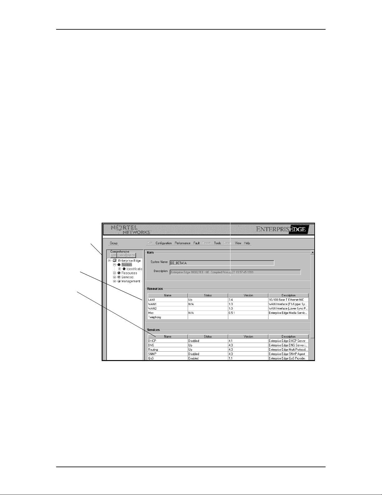
Configuring system settings
1. Click Group and then click Systems or Comprehensive.
2. On the navigation tree click the Enterprise Edge key and then click the
System key.
The screen displays the available Enterprise Edge item settings, resources and
configurable resource services.
3. Configure item settings using Unified Manager and the resource services from
the menu.
Scroll to see any settings that are not displayed.
Unified Manager system set tings
Enterprise Edge Networking Operations Guide P0910464 Issue 01
Page 43

Configuring Unified Manager Settings 43
The Unified Manager system settings are:
Setting Definition
System Name Lets users specify the system name of the Enterprise Edge, Unified
Manager.
Description Shows a description of the Enterprise Edge Unified Manager installed
system.
Resources A configurable listing of all resources installed on the Enterprise Edge
Unified Manager system.
Services A configurable listing of services available for each resource on the
Enterprise Edge Unified Manager system.
The resources and resource services are:
Column Definition
Name Shows each configurable resource service.
Status Shows the status of each configurable resource service.
Version Shows the version of each configurable resource service.
Description Shows a brief description of each configurable resource service.
System name
Unified Manager often shows an example of how to format information to the right
of the box. Type the information in that format.
To enter the system name:
1. In the System Name box type the system name.
2. Press the Tab key to save your changes.
System resource services
1. In the Resource options, click the resource you want to configure.
2. In the Services options, click the resource service you want to configure.
Scroll to see any settings that are not displayed.
P0910464 Issue 01 Enterprise Edge Networking Operations Guide
Page 44

44 Configuring Unified Manager Settings
3. On the menu click Configuration and then click Modify Services.
The services dialog box appears.
4. From the Status list box enable or disable the resource service defined in the
Name box.
5. Click the Save button to return to Unified Manager.
6. Repeat this process to enable or disable:
• DHCP
• DNS
• Routing
•SNMP
•QoS
• VoIP Gateway
• Qos Monitor
•Web Cache
• Voice Record
• TAPI Service Provider
• Voice Service
• Alarm Service
• Voice Mail resource service
•Msc
• Telephony resource
If a resource service is not highlighted prior to prompting resource modification, an
error message appears that asks you to select a row in the table. Click the OK button
to continue.
Enterprise Edge Networking Operations Guide P0910464 Issue 01
Page 45

Configuring Unified Manager Settings 45
Status fields, where available, are the accumulation of 'administrative' and
'operational' status’ of the component queried.
The three administrative statuses that can be assumed by a component are:
• Enabled: the component is enabled to operate in its normal mode, with all
normal parameters set. When the component is enabled, the component can
assume any of its operational statuses.
• Disabled: the component is disabled from operation. None of the component’s
operational statuses are valid in this state.
• Paused: the component is enabled and is running but is currently not accepting
additional service requests.
The two operational statuses that can be assumed by a component are:
• Up: the component is up and running normally
• Down: the component is down, due to some reason - normal or abnormal,
internal or external.
The Status column supports the combined list of these statuses:
• Up: This value is read-only. It indicates that the component is enabled and is
operating normally. For a component like a network interface, this means the
interface is enabled and connected to a valid link. For a service like DHCP, it
means that the service is enabled and is running normally.
• When the current status is 'Up', setting it to 'Enabled' or 'Continue' where
available, is a no-operation. Setting it to 'Disabled' disables the service, by
shutting it down and then disabling it. Where available, setting it to 'Paused'
pauses the service.
• Down: This value is read-only. This value indicates that the user has enabled the
component, and the component is unable to operate in an 'Up' state because of
normal or abnormal, internal or external errors. For example, if a network
interface is not in an 'Up' state because of no connection to an actual physical
link, it is a normal, external error. If a service like DHCP service is not in an 'Up'
state because of internal errors, it is an abnormal, internal error.
• When the current status is 'Down' setting it to 'Enabled' attempts to bring it to
'Up' state again. As a result it may stay at a 'Down' state. Setting it to 'Disabled'
disables the service. Where available, setting it to a 'Paused' or continued state
fail as the service is not yet running.
• Enabled: This value is write-only. This value never appears when read. For a
service that is enabled, one of its operational statuses (that is, Up or Down)
appears when its Status field is read.
P0910464 Issue 01 Enterprise Edge Networking Operations Guide
Page 46

46 Configuring Unified Manager Settings
• When this value is set, it indicates that the user wants to enable the
corresponding component and bring it to an 'Up' state. It is probable that the first
happens. The second action depends on the component. For a network interface,
the 'Up' state does not happen unless user connects a link to the interface. For a
service this may not happen only if the system encounters an error of some kind
during the requested action.
• Disabled: This value can be either read or set. When read, this indi cates that the
component is disabled from operation. When set, it indicates the same, in
addition to taking the component to a 'Down' state before disabling.
• Paused: This value can be either read or set. When read, this indicates that the
service is enabled and is given the command to pause. When set, it indicates the
same, pausing the service further.
• Continue: This value can only be set. It can be set only when the service in a
Paused state. It resumes paused service.
System performance graphs and tables
To access the system performance graphs and tables:
1. On the menu click Performance and then click System CPU Usage Graph.
The System CPU Usage Graph appears.
2. On the menu click Performance and then click System CPU Usage Table.
The System CPU Usage Table appears.
Enterprise Edge Networking Operations Guide P0910464 Issue 01
Page 47

Configuring Unified Manager Settings 47
3. Access the Memory Usage graph and Memory Usage table by following the
steps for System CPU Usable Graphs and Tables.
For information on using performance tables and graphs, refer to Graphs and tables
on page 154.
System Fault Alarm Banner
To access the system fault alarm banner:
1. On the menu click Configuration and then click Fault.
The Alarm Banner dialog box appears.
P0910464 Issue 01 Enterprise Edge Networking Operations Guide
Page 48

48 Configuring Unified Manager Settings
System Alarm Banner Message Listing
Accessing System Tools
Enterprise Edge Networking Operations Guide P0910464 Issue 01
Page 49

Accessing System Save Options
Configuring Unified Manager Settings 49
System name, date and time
To change the system name, date and time:
1. Click the System navigation key to expand the navigation tree.
The System Settings dialog box appears.
Clicking the System navigation key expands the navigation tree but doesn’t
display the summary of configurable Identification resources.
The System Settings are:
Setting Definition
Name Lets users specify the name for the Enterprise Edge system. The Enterprise
Edge system must have a unique name in the connected network (LAN or
WAN) so that no two Enterprise Edge servers that can reach each other
through IP network do not have the same name. The name mu st b e le ss than
15 characters in length, cannot contain special characters like “/;,” etc.
Date Lets users set the current date for the Enterprise Edge system. Because the
value for the date changes, save the changes as soon as the new date is
entered.
Time Lets users set the current time for the Enterprise Edge system. Because the
value for the time keeps changing, save the ch anges as s oon as the n ew time
is entered. Use the 24-hour format to set the date. The seconds field is
optional.
2. On the navigation tree click Identification to view the available system
settings to configure.
The System Identification dialog box appears.
P0910464 Issue 01 Enterprise Edge Networking Operations Guide
Page 50

50 Configuring Unified Manager Settings
Note: Clicking the Identification navigation key causes the key to disappear.
You must click Identification to display the configurable system
settings.
3. In the System Name box type the system name.
4. In the Date box type the current date.
5. In the Time box type the current time.
6. Press the Tab key to save the changes.
7. Clicking the System navigation key to close the navigation tree.
Enterprise Edge Networking Operations Guide P0910464 Issue 01
Page 51

Configuring Resources Settings
Configuring Resources includes configuring:
• LAN
• WAN Settings
• MSC Settings
• Telephony (PBX) Settings
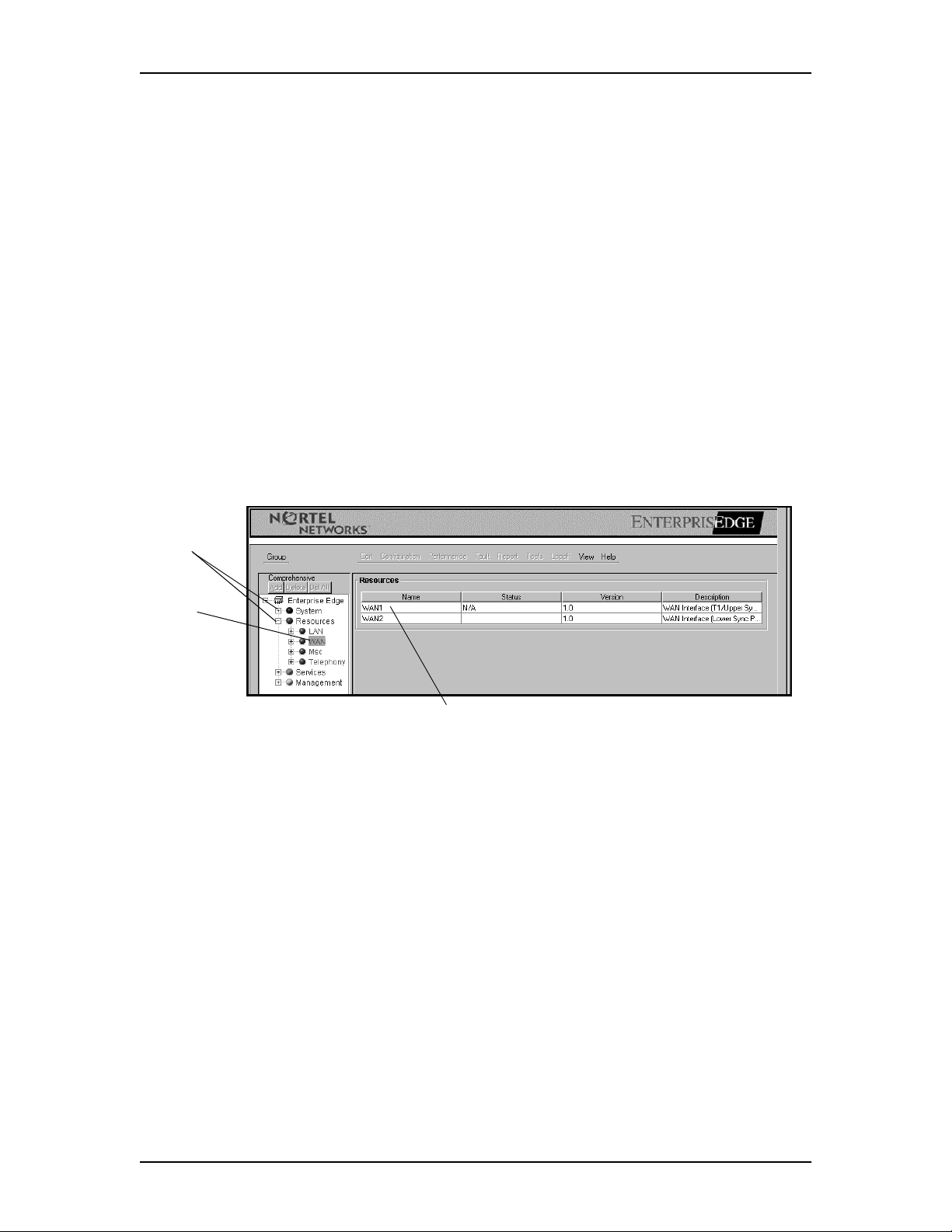
To open the Unified Manager Resources screen:
1. On the menu click Group and then click Resources or Comprehensive.
2. On the navigation tree click Enterprise Edge and then click the Resources
keys.
The available Enterprise Edge resources appear.
5
3. Click the Resources navigation key to expand the navigation tree.
P0910464 Issue 01 Enterprise Edge Networking Operations Guide
Page 52

52 Configuring Resources Settings
The columns that are displayed when the system, resources, services, or
management settings are activated are:
Column Definition
Name The name column lists the available configurable resources.
Status The status column lists the operating status of each configurable resource.
Version The version column lists the version of each configurable resource.
Description The description column gives a brief description of the interface for each
configurable resource.
LAN
You configure LAN resource settings from Unified Manager.
If your Enterprise Edge server has more than one LAN interface, multiple items
appear under LAN resources. To configure other LAN interfaces, follow the
instructions given here for LAN1.Choose LAN from the navigation tree to view the
available LAN resources to configure.
Note: Clicking the LAN navigation key expands the navigation tree, but
doesn’t display the summary of configurable LAN resources.
4. Click the LAN navigation key to expand the navigation tree.
Enterprise Edge Networking Operations Guide P0910464 Issue 01
Page 53

Configuring Resources Settings 53
5. On the navigation tree click LAN1.
Clicking the LAN1 navigation key causes the key to disappear. You must
click LAN1.
The LAN Summary screen appears.
The LAN Summary settings are:.
Setting Definition
IP Address Lets users specify the IP address of the LAN interface in a valid dot format.
Type the address in the following format: 10.10.10.1.
The value for this field is valid only if the LAN interface is enabled.
SubNet Mask Lets users specify the subnet mask of the LAN interface. Type the data in
the following dot format 255.255.255.0.
Physical Address Lets users to view the physical address of the LAN interface.
If the IP Address or subnet mask of the LAN interfaces changes, a DHCP
scope associated with the LAN interface is created in the DHCP server
running on the Enterprise Edge server. This scope contains all necessary
parameters to the clients of the DHCP server configured so that they use
Enterprise Edge as their default gateway and a WINS server. The scope also
contains default parameters for the range of the addresses, based on the
address of the Enterprise Edge interface and subnet mask. Navigate through
the services screen in the user interface to see DHCP settings for the scope.
Description Lets users view a description of the network interface card supporting the
LAN interface.
Version Lets users view the version indicator of the LAN interface.
Speed Lets users view the speed of the connection to the LAN interface.
The value for this field is valid only if the LAN interface is enabled.
P0910464 Issue 01 Enterprise Edge Networking Operations Guide
Page 54

54 Configuring Resources Settings
Setting Definition
Connection Type Lets users specify the connection type to the LAN interface.
The following values are supported and are interpreted as follows:
Auto Sense: The interface uses 'auto negotiation' protocol to choose the
maximum possible speed of the connection. Depending upon the connected
device, the interface can choose '100 MB' or '10MB', full-duplex, or half-
duplex.
The receiving end’s speed and connection type determines the mode of
transmission. For example, if the receiving end is another PC port, or a
bridge/switch port, the full duplex of operation is possible; if the receiving
end is a shared media port (like hub port), only half-duplex of mode is
possible.
10 MB Half: Speed is set to 10 MB/s and mode to half-duplex.
10 MB Full: Speed is set to 10 MB/s and mode to full-duplex
10 MB Auto: The speed is set to 10 MB/s and the mode is automatically
chosen by the interface, using auto-negotiation protocol. This mode is
chosen to limit the maximum traffic coming in to Enterprise Edge to 10 MB,
while enabling the auto-negotiation feature for easier interconnection.
Usually, you limit the incoming traffic if you notice that the bursty traffic
from the connected LAN is degrading the quality of voice calls carried
through VoIP over WAN. Though the LAN traffic gets lower priority in
Enterprise Edge, their high rate of arrival to the Enterprise Edge server
generates too may interrupts in the system that cause degraded quality in
voice calls carried as VoIP.
100 MB Half: Speed is set to 100 MB/s and mode to half-duplex 100 MB
Full: Speed is set to 100 MB/s and mode to full-duplex.
Status Lets users view the current status of the LAN interface.
The possible states are:
Up: the resource is operational.
Down: the resource is not operational.
Consult your System Administrator for the appropriate configuration information
before changing the settings
To modify the configuration of the LAN1 settings:
1. In the IP Address box type the IP address.
An example of how to format the information is shown at the right of the box.
2. In the SubNet Mask box type the subnet mask
3. From the Connection Type list select the connection type.
4. Press the Tab key to save the settings.
Enterprise Edge Networking Operations Guide P0910464 Issue 01
Page 55

Configuring Resources Settings 55
To view LAN performance:
1. On the menu, click Performance and then click LAN Graph.
The LAN Graph Statistic Chart appears.
2. On the menu, click Performance and then click LAN Table.
The LAN Graph Statistic Table appears.
For information on using performance tables and graphs, refer to Graphs and tables
on page 154.
3. Click the LAN navigation key to close the navigation tree.
P0910464 Issue 01 Enterprise Edge Networking Operations Guide
Page 56

56 Configuring Resources Settings
WAN primary links
You configure WAN resource settings from Unified Manager.
WAN Interfaces have names like WAN1 and WAN2. If your Enterprise Edge
server has a permanent WAN card, WAN1 and WAN2 are interfaces from this card.
They can run Frame Relay or PPP on a permanent WAN Link operating at T1
speed. Click on these interfaces to see their description.
If your Enterprise Edge server also contains a modem card with dial up interfaces,
they appear as WAN3, WAN4 and so on. Click on these interfaces to see their
description. If your Enterprise Edge server does not have a WAN card, dial-up
interfaces appear as WAN1, WAN2 and so on.
The configurable parameters and options are different for permanent WAN links
and for dial-up WAN links. In this document, it is assumed that WAN1 and WAN2
are permanent WAN links and WAN3 and others, are be dial-up interfaces.
To view the WAN primary links
1. Click WAN to view the available WAN resources to configure.
2. Click the WAN navigation key to expand the navigation tree.
Clicking the WAN navigation key expands the navigation tree but doesn’t
display the summary of configurable WAN resources.
3. On the navigation tree, click WAN1 or WAN2.
Clicking the WAN1 or WAN2 navigation key causes the key to disappear.
You must click WAN1 or WAN2.
The screen displays the WAN Summary, WAN Line Parameters, WAN Frame
Relay Parameters, WAN PPP Parameters, and PVC Congestion Control
settings.
Note: The WAN Frame Relay Parameters do not appear unless frame relay is
chosen as your link protocol in the WAN Summary. To display the
WAN frame relay parameters, from the Link Protocol list box select
Frame Relay. Press the Tab key to update the screen. A configurable
WAN Frame Relay Parameters dialog does not appear unless the
current link protocol is PPP.
4. Scroll to view any settings that are not displayed.
5. Configure the WAN Summary, WAN Line Parameters, WAN Frame Relay
Parameters and WAN PPP Parameters screen from Unified Manager.
Configure the PVC congestion control screen using the menu.
Enterprise Edge Networking Operations Guide P0910464 Issue 01
Page 57

Configuring Resources Settings 57
If your current link protocol is Frame Relay, you may have to configure WAN
Frame Relay parameters and PVC Congestion Control entries. If your current link
protocol is PPP, you may have to configure WAN PPP Parameters.
If the WAN port you are configuring is a T1 Port, you may have to configure WAN
Line Parameters. If the port you are configuring is a synchronous (Sync) port, W AN
Link Parameters have no effect, and are ignored. See the description of the port in
WAN Summary section to see which port you are configuring.
P0910464 Issue 01 Enterprise Edge Networking Operations Guide
Page 58

58 Configuring Resources Settings
WAN Primary Link Summary Parameters
The WAN summary settings are:
Setting Definition
IP Address Lets users specify the IP address of the WAN interface in a valid dot format.
Type the data in the following dot format: 10.10.10.1.
SubNet Mask Lets users specify the subnet mask in a valid dot format of the WAN interface.
Type the data in the following dot format 255.255.255.0.
Physical Address Shows the physical address of the WAN interface.
Description Shows the description of the network interface card that supports the WAN
interface.
Version Shows the version indicator of the WAN interface.
Speed Shows the operational speed of the WAN interface.
Status Shows the current resource status of the WAN interface.
The possible states are:
Up: the resource is operational.
Down: the resource is not operational.
Link Protocol Lets users specify PPP or frame relay protocol.
If you change the link protocol, the configuration screen changes to include
fields corresponding to the link protocol you choose. To ensure proper
operation, always refresh the page by clicking
Compression
Speed
Frame Size Lets users specify the maximum frame size for the layer-2 packet carried on
Lets users specify fast, medium, normal, slow, or no data compression
configuration.
this port.
View
and then
Refresh
.
To modify the configuration of the WAN1 or WAN2 summary screen:
6. In the IP Address box type the IP address.
7. In the SubNet Mask box type the subnet mask.
8. From the Link Protocol list box choose Frame Relay or PPP.
Note: If you choose Frame Relay, press the Tab key to update the screen. A
configurable WAN Frame Relay Parameters screen appears.
9. From the Compression Speed list box select the compression speed.
10. In the Frame Size box type the frame size.
11. Press the TAB key to save your settings.
Enterprise Edge Networking Operations Guide P0910464 Issue 01
Page 59

Configuring Resources Settings 59
WAN Primary Link Line Parameters
The WAN Link Line Parameters settings are:
Setting Definition
Channel Rate Lets users set the data rate for each of the DS0 channels in the T1 line.
Clock Source Lets users set an internal or external T1 clock source.
Frame Type Lets users set the type of framing to be adopted in the T1 line.
You can select either SF(D4) or ESF for frame type. SF(D4) transmits
superframes consisting of 12 individual frames. ESF transmits superframes
consisting of 24 individual D4 frames and provides enhanced signaling and
synchronization.
ESF lets you testing the digital line while it is in use.
Always use the frame type that the equipment at the receiving end expects.
Line Coding Lets users set the type of encoding used in the T1 line.
You can select either B8ZS or AMI for this parameter. B8ZS (Bipolar with 8
Zero Substitution) line coding replaces a block of eight consecutive binary zeros
with an 8-bit B8ZS code containing bipolar violations in the fourth and seventh
bit positions of the substituted code. In the receiving direction, the B8ZS code is
detected and replaced with eight consecutive binary zeros.
AMI line coding is also bipolar: a binary zero is transmitted as zero volts, and a
binary 1 is transmitted as either a positive or negative pulse, opposite in polarity
to the previous pulse.
Always use the line coding method that the equipment at the receiving end
expects.
Line Polarity Lets users set normal or inverted line polarity in the T1 line. The option inverted
is meaningful only if LineCoding is AMI.
Pulse Density Lets users control whether the DSU/CSU maintains the minimum level of 1s on
the line for AMI encoding.
Channel List Lets users create a list of channels used in the T1 line.
You can specify multiple channel numbers in a comma-separated list. Each item
in the list can contain a range of channel numbers, with the limits of the range
separated by a hyphen character. For example, this is a valid value for channel
list: 3,5,6,10-15,18,20-23. If you use all of the channels, specify it by using the
string All.
P0910464 Issue 01 Enterprise Edge Networking Operations Guide
Page 60

60 Configuring Resources Settings
To modify the configuration of the WAN1 or WAN2 Line Parameters screen:
1. Scroll to view the WAN Line Parameters screen.
2. From the Channel Rate list box select the channel rate.
3. From the Clock Source list box select the clock source.
4. From the Frame Type list box select the frame type.
5. From the Line Coding list box select the line coding.
6. From the Line Polarity list box select the line polarity.
7. From the Pulse Density list box select the appropriate pulse density and close
the list box.
8. In the Channel List box.type the channel list.
Specify a list of channels numbers or their ranges separated by a comma or
hyphen. Ranges can be mixed with individual entries.
9. Press the Tab key to save the settings.
Enterprise Edge Networking Operations Guide P0910464 Issue 01
Page 61

Configuring Resources Settings 61
WAN Primary Link Frame Relay Parameters
The WAN Frame Relay Parameters are:.
Setting Definition
LMI Type Lets users set the type of link management protocol used on this link.
This value must match the corresponding value set in the Frame Relay
service provider’s switch. Permitted values are ANSI, LMI, and
CCITT. The default setting is ANSI.
Polling Interval Lets users set a value, in seconds, as an interval between LMI status
inquiry messages. This v alue must match the corr espondi ng value set in
the Frame Relay provider’s switch. Permitted values are between 5-30
(in seconds). The default setting is 10.
Full Enquiry Interval Lets users set the maximum number of LMI Status Enquiry messages
sent before sending a Full Status Enquiry request. This value must
match the corresponding value set in the Frame Relay provider’s
switch. Permitted values are between 1 and 255 (in seconds). The
default setting is 6.
Error Threshold Lets users set the maximum number of consecutive failures permitted
in LMI Status Enquiry before marking the link non-operational. It is
also the number of successful consecutive LMI Status Enquiry
messages that must be received before marking a link as operational.
Permitted values are between 0 and MAXINT. The default setting is 3.
Monitored Events Lets users s et the number of even ts sampled for making decis ions about
the error threshold. Set the number higher than the values set in the
error threshold. Permitted values are a number between 0 and
MAXINT. The default setting is 4.
DS Code Lets users set the differentiated services code (DSCode) recognized by
the frame relay driver for prioritization. This value is used as a mask
value. When an IP packet is sent down, the frame-relay driver checks if
the packet's DSCode field (known as TOS byte in earlier documents)
has any of the bits specified in this field set (a bitwise AND operation is
performed between this field's value and the DSCode field of the IP
packet and the result is checked for 0). If any of the bits is set (result is
non-zero), the frame relay network is signaled to handle this packet
with priority by clearing the 'D/E' (discard eligibility) bit in the frame
relay packet header. If none of the bits specified in this field are set in
the IP packet header, 'D/E' bit is set in the frame-relay packet header,
marking the packet as a likely candidate for packet drop in case of
congestion in the frame relay network.
This field's value carries the same semantics as the 'differentiated
services codepoint' discussed in RFC2474. The least significant two
bits are ignored.
Compression Enabled
PVCs
Lists PVCs on which compression is enabled. If the compression field
is Disabled, the field does not have any meaning. If the compression
level Enabled, compression and decompression are performed on the
data going to and coming from the PVCs in this list.
The value can be a comma-separated list of DLCI numbers. You can
specify a range of DLCIs b y specify ing th e lower and u pper bound aries
by a hyphen. You can mix individual numbers and ranges.
P0910464 Issue 01 Enterprise Edge Networking Operations Guide
Page 62

62 Configuring Resources Settings
Setting Definition
Access Rate Lets users set, in kbps, the maximum access rate on the interface
running frame-relay. The frame-relay congestion control engine uses
this value to limit or shape traffic. Specify a value computed using the
T1 channels available for data communication on the port attached to
this interface and their data rates.
To modify the configuration of the WAN Frame Relay Parameters:
1. Scroll to locate the WAN Frame Relay Parameters screen.
2. From the LMI Type list box select the LMI type.
3. In the Polling Interval box type the polling interval in seconds.
4. In the Full Enquiry Interval box type the full enquiry interval.
5. In the Error Threshold box type the error threshold.
6. In the Monitored Events box type the appropriate monitored events.
7. In the DS Code box type the DS code.
8. In the Compression Enabled PVCs box type the compression.
9. In the Access Rate box type the access rate in kbps.
10. Press the Tab key to save the settings.
Enterprise Edge Networking Operations Guide P0910464 Issue 01
Page 63

Configuring Resources Settings 63
The WAN PVC Congestion Control settings are:
Setting Definition
Entry (CC#) Uniquely identifies the congestion control entry on the interface. Use
the format specified for the entry identifier. It must include the prefix
'CC' followed by a unique number in the table. For example, 'CC2' is a
valid number. If you don't use consecutive numbers while adding the
entry, the system adjusts them to be consecutive. If you specify an
existing entry while adding an entry, the existing entry is modified with
new values. While modifying an entry, the name can't be changed.
DLCI Lets users set the DLCI number for the PVC to be congestion
controlled. If a DLCI is not configured, it is not congestion controlled.
Enterprise Edge uses one-second intervals to measure this parameter.
CIR Lets users set, in kbits, the carrier guarantees the router transmits over a
specified time interval when congestion is not present.
Enterprise Edge uses one-second intervals to measure this parameter.
Committed Burst (bC) Lets users to define the number, in kbits, of bits the router transmits
over a specified time interval if congestion is present. Usually this value
is set for 1/4 the value of the CIR.
Enterprise Edge uses one-second intervals to measure this parameter.
Excess Burst (Be) Combined with the committed burst rate, lets users set, in kbits, the
maximum number of bits the router transmits over a specified time
interval if there is no congestion. Both Be and bC must be less than or
equal to the line speed.
To add PVC congestion control:
1. On the menu click Configuration and then click Add PVC Congestion
Control.
The PVC Congestion Control dialog box appears.
If an entry range has not been selected an error message appears.
2. In the Entry (CC#) box type the entry that looks like “CCxx” where “xx” is a
unique integer.
P0910464 Issue 01 Enterprise Edge Networking Operations Guide
Page 64

64 Configuring Resources Settings
3. In the DLCI box type the DLCI.
4. In the CIR (kbps) box type the CIR in kbps.
5. In the Committed Burst BC (kbits) box type the committed burst in kbits.
6. In the Excess Burst BE (kbits) box type the excess burst in kbits.
7. Click the Save button to return to Unified Manager.
To modify PVC congestion control:
1. Click an entry in the PVC Congestion Control range.
2. On the menu click Configuration and then click Modify PVC Congestion
Control.
The PVC Congestion Control dialog box appears.
3. Click any box that requires modification and type the necessary changes.
4. Click the Save button to return to Unified Manager.
To delete PVC congestion control:
1. Click an entry in the PVC Congestion Control range.
2. On the menu click Configuration and then click Delete PVC Congestion
Control.
A message appears that asks you to confirm the deletion.
3. Click the Yes button to delete PVC congestion and return to Unified Manager.
Enterprise Edge Networking Operations Guide P0910464 Issue 01
Page 65

Configuring Resources Settings 65
WAN Primary Link PPP parameters
The WAN PPP Parameters are:
Setting Definition
Keep Alive Interval Lets users specify the interval between kept alive messages sent when
there is no regular traffic on the PPP link.
Cisco’s Encapsulation
Mode
Lets users enable or disable the Cisco compatibility mode.
To set the WAN PPP parameters:
1. Scroll to the WAN PPP Parameters screen.
The WAN PPP Parameters screen appears.
2. In the Keep Alive Interval box type the keep alive interval in seconds.
3. From the Cisco’s Encapsulation Mode list box to enable or disable the Cisco
compatibility mode.
P0910464 Issue 01 Enterprise Edge Networking Operations Guide
Page 66

66 Configuring Resources Settings
WAN Primary Link performance graphs and tables
To access the WAN Primary Link performance graphs and tables:
1. On the menu click Performance and then click WAN Graph.
The WAN Graph Statistic Chart appears.
2. On the menu click Performance and then click WAN Table.
The WAN Table: Statistic Table appears.
For information on using the WAN statistic c hart and the WAN st atistic table, refe r
to Graphs and tables on page 154.
Enterprise Edge Networking Operations Guide P0910464 Issue 01
Page 67

Configuring Resources Settings 67
WAN Backup Links
WAN3 and WAN4 are dial up interfaces that are configured according to the V.90
modem in the Enterprise Edge server. You must click WAN3 to see its description.
Dial up WAN Links always use PPP as link-layer protocol. They must be connected
to PPP capable RAS Servers that can run RIP or can accept static routes for proper
operation.
1. On the navigation tree, click WAN3.
Clicking the WAN3 navigation key causes the key to disappear. You must
choose WAN3.
The WAN Summary, WAN Link Parameters, and WAN Access Parameters
screen appears.
2. Scroll to see any settings that are not displayed.
1. From the IP Address list box select the appropriate IP address assignment or
type a new value.
2. From the Status list box enable or disable the connection to the backup link.
3. Press the Tab key to save the settings.
P0910464 Issue 01 Enterprise Edge Networking Operations Guide
Page 68

68 Configuring Resources Settings
WAN Backup Link Summary Parameters
The WAN Summary contains these settings:
Setting Definition
IP Address Lets users set the IP address of the modem interf ace in a valid do t format when
it connects.
Users can set a fixed IP Address for the dial-up interface. If a fixed address is
specified, it is used by Enterprise Edge to connect to the receiving end.
Instead, users can choose RemoteAssigned to indicate that Enterprise Edge
must obtain an IP address from the remote end and use it. The address
obtained depends on the RAS server that the Enterprise Edge server connects
to.
Description Shows a description for the subsystem that is encapsulated by the DLL.
Version Shows the version for the subsystem that is encapsulated by the DLL.
Status Lets users set the modem interface resource status.
The possible states are:
Up: the auto WAN backup service is enabled and the d ial-up link is cu rrently
connected.
Down: the auto WAN backup service is enabled and the dial-up link is
currently
disconnected.
Enabled: the interface is enabled for use by the auto-backup server.
Disabled: the auto WAN backup service is disabled.
Enterprise Edge Networking Operations Guide P0910464 Issue 01
Page 69

Configuring Resources Settings 69
WAN Backup Link Parameters
The WAN Link Parameters are:
WAN Link Parameters Dialog Definitions
Setting Definition
Telephone Number Lets users specify a telephone number to be used to connect using
the modem interface. If needed, include area codes, if any, and all
necessary digits to dial an external number.
Alternate Telephone
Number
Connect Rate Lets users specify the initial speed (in bits per second) for the
Dial Retries Lets users specify the number of tries the system attempts to make a
Dial Interval Lets users specify the interval, in seconds, between successive
Speaker Mode Lets users enable or disable the speaker during initial link
IP Header Compression Lets users enable or disable IP header com pression. To function, the
Software Compression Lets users enable or disable data compression in the software,
Hardware Compression Lets users enable or disable data compression in the hardware
PPP LCP Extensions Lets users specify whether or not to enable or disable PPP LCP
Lets users specify an alternate number to be used to connect using
the modem interface. Include area codes, if any, and all necessary
digits to dial an external number.
modem to connect. Set to the maximum permissible value for best
results. Permitted values: 57600, 38400, 19200, 9600, 4800. Note:
This is the initial rate, actual rate is always negotiated.
link operational before marking it non-operational. A positive
number must be used.
attempts to make a link operational.
establishment.
receiving end must utilize this feature to work.
instead of the modem. For dial-up connections, Unified Manager
uses Microstate Point-to-Point Compressio n algorithm (MPPC).
instead of the software.
extensions that include Time-Remaining, Identification, and
Callback features. The Callback feature is not supported even if
LCP extension is enabled.
1. Scroll to see the WAN Link Parameters settings.
P0910464 Issue 01 Enterprise Edge Networking Operations Guide
Page 70

70 Configuring Resources Settings
Accessing WAN Link Parameters
2. In the Telephone # box type your telephone number choice.
3. In the Alternate Telephone # box type your alternate telephone number
choice.
4. From the Connect Rate list box select your connection rate choice.
5. In the Dial Retries box type the number of times to attempt dialing if the
connection fails.
6. From the Speaker Mode list box select your speaker mode choice.
7. From the IP Header Compression list box select enable or disable.
8. From the Software Compression list box select enable or disable.
9. From the Hardware Compression list box select enable or disable.
10. From the PPP LCP Extensions list box select enable or disable.
11. Press the Tab key save the settings.
Enterprise Edge Networking Operations Guide P0910464 Issue 01
Page 71

Configuring Resources Settings 71
WAN Backup Access Parameters
The WAN Access Parameters are:
Setting Definition
Authentication Lets users specify the authentication type for the link.
Users can choose AllowClearText or EncryptedOnly. If
EncryptedOnly is selected, only encrypted authentication such as
CHAP is used on this interface during PPP authentication protocol. If
AllowClearText is selected, CHAP is used first and if the receiving
end of the link declines, PAP is used to authenticate the link user.
Two Way Authentication Lets users enable or disable link authentication in both directions.
User ID (name password) Lets users specify a user name and a password that the link uses to
authenticate itself while dialing out to another router.
1. Scroll to find the WAN Access Parameters.
2. From the Authentication list box select the authentication type.
3. From the Two Way Authentication list box select the two-way
authentication type.
4. In the User ID (name password) box type the user ID, separating the user
name and password with a space.
5. Press the Tab key to save the settings.
6. Click the WAN navigation key to close the navigation tree.
P0910464 Issue 01 Enterprise Edge Networking Operations Guide
Page 72

72 Configuring Resources Settings
MSC
1. On the Navigation Tree click MSC to view the available MSC resources to
configure.
The MSC Resources screen appears.
Enterprise Edge Networking Operations Guide P0910464 Issue 01
Page 73

Configuring Resources Settings 73
Telephony
1. On the Navigation Tree click Telephony to view the available telephony
resources to configure.
The Telephony Resources screen appears.
Accessing Telephony R e s ources
2. Click the Resources navigation key to close the navigation tree.
P0910464 Issue 01 Enterprise Edge Networking Operations Guide
Page 74

74 Configuring Resources Settings
Enterprise Edge Networking Operations Guide P0910464 Issue 01
Page 75

Configuring Services Settings
Configuring Services Settings includes:
• DHCP Settings
• DNS Settings
• Web Caching/Proxy
• Routing settings
To access the services settings:
1. On the menu click Group and then click Services
or
click Group and then click Comprehensive.
2. On the navigation tree click the Enterprise Edge key and then click the
Services key.
The available Enterprise Edge services appear.
6
3. Click the Services navigation key to expand the navigation tree.
P0910464 Issue 01 Enterprise Edge Networking Operations Guide
Page 76

76 Configuring Services Settings
DHCP
To configure DHCP services settings:
1. On the navigation tree click DHCP to view the available resources to
configure.
Click the DHCP navigation key to expand the navigation tree, but clicking on
the key doesn’t display the summary of configurable DHCP services. You
must click DHCP.
The DHCP Global Options and Summary settings appear.
2. Scroll to view any settings not displayed on Unified Manager.
Enterprise Edge Networking Operations Guide P0910464 Issue 01
Page 77

Configuring Services Settings 77
The settings in the DHCP Global Options and DHCP Summary screen are:
Setting Definition
Domain Name Lets users specify a domain name that is passed to the client when Enterprise
Edge responds to a client’s DHCP requests.
This setting is automatically set to 'Domain' field in 'DNS Summary' page.
This means that all the DHCP clients of an Enterprise Edge server are in the
same DNS domain as the Enterprise Edge server. This is also correct since
Enterprise Edge runs only a DNS cache and does not introduce another DNS
zone.
Change the Domain setting in the DNS Summary to make a change in this
setting. Occasionally you can change the value of Domain in DHCP. If you
do, first make any changes to Domain in the DNS Summary to avoid
overwriting your changes.
WINS Node
Type
Description Shows a description of the Enterprise Edge server.
Version Shows the version number of the Enterprise Edge server.
Status Lets users enable or disable the DHCP server. When disabled, clients need to
Lets users specify a clients WINS node type.
Enterprise Edge automatically sets this value to 8 (indicating H-Node) if the
IP Address is changed on any of the LAN interfaces. All DHCP clients of
Enterprise Edge are set to h-node type when they get their IP properties from
Enterprise Edge. This setting configures the DHCP client PCs to use p-node
name resolution before resor ting to b-n ode name res olution, which is effi cient
when there is a WINS server configur ed for the network. Enter prise Edge als o
includes a WINS server.
Other options available for this field are:
1: indicates a b-node that uses broadcast mechanism for NetBIOS name
resolution
2: indicates a p-node that uses point-to-point mechanism involving a WINS
Server for NetBIOS name resolution
4: indicates a m-node that first uses broadcast and then point-to-point
mechanism for NetBIOS name resolution.
be assigned static IP addresses.
3. In the Domain Name box type the appropriate domain name.
This is set in Enterprise Edge configuration. Use caution if you change it.
4. In the WINS Node Type box type the appropriate WINS Node Type.
This is set in Enterprise Edge configuration. Use caution if you change it.
5. From the Status list box select either enable or disable.
6. Press the Tab key to save the settings.
P0910464 Issue 01 Enterprise Edge Networking Operations Guide
Page 78

78 Configuring Services Settings
DHCP LAN
1. Click the DHCP navigation key to expand the navigation tree.
2. On the Navigation tree click LAN1.
Clicking the LAN1 navigation key causes the key to disappear. You must
choose LAN1 to display the configurable DHCP LAN1 services. If your
Enterprise Edge system has multiple LAN interfaces, if is possible that you
see multiple DHCP Scopes under DHCP. They are be named LAN1, LAN2.
This section describes configuring DHCP scope for LAN1. Follow the same
instructions to configure any of the parameters under scope for LAN2.
The screen displays the LAN Scope Specific Options, Address Range, and
Excluded Address Range dialog box.
3. Scroll to view settings not displayed on Unified Manager.
4. You configure the scope-specific options dialog box from Unified Manager.
The LAN address range and the LAN excluded address services screen is
configured through the menu.
Enterprise Edge Networking Operations Guide P0910464 Issue 01
Page 79

Configuring Services Settings 79
Note: If the IP Address or subnet mask for a LAN interface is changed, the
corresponding DHCP scope is created or modified for the interface.
This operation also involves setting default values for some
parameters. By default, Enterprise Edge sets the IP Address of
corresponding LAN interface to DNS Server, WINS Server, Default
Gateway options of the scope. It also sets the lease time to 3 days,
creates a range of addresses for the scope. If the IP Address of the
LAN interface is in the lower half of the subnet, the address range set
for the scope includes all the address above the LAN interface address.
If the IP Address of the LAN interface is in the upper half of the
subnet, the address range set for the scope includes all the address
below the LAN interface address. By default, the scope is enabled.
The DHCP LAN1 Scope Specific Options, Address Range and Excluded Address
Range settings are:
Setting Definition
DNS Server Lets users specify the clients’ DNS server.
The value for this parameter is automatically assigned by Enterprise Edge's
auto-configuration system. If the IP Address or subnet mask for the
corresponding LAN interface is changed, this value gets overwritten. Use
caution when changing this value.
WINS Server Lets users specify the client’s WINS server.
The value for this parameter is automatically assigned by Enterprise Edge's
auto-configuration system. If the IP Address or subnet mask for the
corresponding LAN interface is changed, this value gets overwritten. Use
caution when changing this value.
Default Gateway Lets users specify the client’s default next-hop router.
The value for this parameter is automatically assigned by Enterprise Edge's
auto-configuration system. If the IP Address or subnet mask for the
corresponding LAN interface is changed, this value gets overwritten. Use
caution when changing this value.
Lease Time Lets users specify the time, in seconds, from an address assignment until
the client’s lease expires.
Scope Status Lets users enable or disable the scope.
Address Range Lets users specify the valid IP addresses that are assigned to DHCP clients.
Excluded Address Lets users specify IP addresses that are not available to DHCP clients.
P0910464 Issue 01 Enterprise Edge Networking Operations Guide
Page 80

80 Configuring Services Settings
To modify the configuration of the Scope Specific Options screen:
1. In the DNS Server box type the name of the DNS server.
This field is configured automatically. Use caution when you change it.
2. In the WINS Server box type the name of the WINS server.
This field is configured automatically. Use caution when you change it.
3. In the Default Gateway box type the default gateway.
This field is configured automatically. Use caution when you change it.
4. In the Lease Time box type the lease time.
This field is configured automatically. Use caution when you change it.
5. From the Scope Status list box select the scope status.
6. Press the TAB key to save the settings.
To modify, add, or delete a DHCP address range or excluded address range:
1. Assign only one IP Address range for a DHCP Scope and exclude ranges of
addresses in it from being assigned to clients.
To modify address ranges:
1. Click an address in the address range table.
2. On the menu click Configuration and then click Modify Address Ranges.
The Address Range dialog box appears.
3. Type the necessary changes in any of the boxes.
4. Click the Save button to return to Unified Manager.
Enterprise Edge Networking Operations Guide P0910464 Issue 01
Page 81

Configuring Services Settings 81
To add an address range:
1. On the menu click Configuration and then click Add Address Range.
The Address Range dialog box appears.
2. In the Range box type the range.
The range field uniquely identifies a range value in the scope. The value for
this field is used as key, and must follow certain conventions. It must always
start with the prefix 'R' followed by a unique number identifying the range in
the table. For example, 'R2' is a valid name.While adding, specify nonrecurring values for the unique number. While adding, if you specify an
existing range name, it modifies the existing range. Using non-sequential
numbers results in automatic reassignment of sequential numbers. When you
modify a range, you can't change the range name. The range name does not
have any significance other than identifying an entry.
3. In the Start Address box type the start address.
4. In the End Address box type the end address.
Scroll to see any fields that are not displayed.
Make sure the start address and end address are in the same subnet.
5. Click the Save button to return to Unified Manager.
To delete address ranges:
1. Click an address in the Address Range table.
2. On the menu click Configuration and then click Delete Address Ranges.
A message appears asking you to confirm the deletion.
3. Click the Yes button to confirm the deletion and return to Unified Manager.
Note: Deleting or modifying an IP Address range removes any excluded
addresses that are completely contained in the original address range
value.
P0910464 Issue 01 Enterprise Edge Networking Operations Guide
Page 82

82 Configuring Services Settings
To modify excluded address ranges:
1. Click an excluded address in the Excluded Address Range table.
2. On the menu click Configuration and then click Modify Excluded Address
Ranges.
The Excluded Address Range dialog box appears.
3. In any box that requires modification type the necessary changes.
4. Click the Save button to return to Unified Manager.
To add excluded address ranges:
1. On the menu click Configuration and then click Add Excluded Address
Range.
The Excluded Address Range dialog box appears.
2. In the Range box type the range.
Note: The range field uniquely identifies an excluded range value in the
scope. The value for this field is used as key, and must follow certain
conventions. It must always start with the prefix 'E' followed by a
unique number identifying the range in the table. For example, 'E2' is a
valid name. While adding, specify non-recurring values for the unique
number. While adding, if you specify an existing excluded range
name, it modifies the existing range. Using non-sequential numbers
results in automatic reassignment of sequential numbers. When you
modify an excluded range, you can't change the range name. The
excluded range name does not have any significance, other than
uniquely identifying an entry.
3. In the Start Address box type the start address.
4. In on the End Address box type the end address.
Scroll to see any fields that are not displayed.
Note: Make sure the start address and end address are in the same subnet,
and an excluded address range is completely contained in an IP
address range specified for the subnet.
5. Click the Save button to return to Unified Manager.
Enterprise Edge Networking Operations Guide P0910464 Issue 01
Page 83

Configuring Services Settings 83
To delete excluded address ranges:
1. Click an excluded address in the Excluded Address Range table.
2. On the menu click Configuration and then click Delete Excluded Address
Ranges.
A message appears that asks you to confirm the deletion.
3. Click the Yes button to confirm the deletion and return to Unified Manager.
4. Click the DHCP navigation key to close the navigation tree.
P0910464 Issue 01 Enterprise Edge Networking Operations Guide
Page 84

84 Configuring Services Settings
DNS
To configure DNS services settings:
1. On the navigation tree click DNS.
Clicking the DNS navigation key causes the key to disappear. You must click
DNS to view the available configurable DNS services.
The DNS Summary screen appears.
The DNS Summary settings are:
Setting Definition
Description Lets users view the description of the server in cache mode.
Version Lets users view the version of the software interface.
Status Lets users enable or disable the DNS cache proxy in Enterprise Edge.
Domain Lets users specify the domain name that Enterprise Edge and its DHCP clients
uses. When modified, contents of this setting are automatically copied to
Domain Name global options (O15) under DHCP.
Primary Server Lets users specify the primary server IP address in a valid dot format. More
than one address can be specified separated by a space; DNS cache uses them
in the specified order to resolve names.
Forward Timeout Lets users specify the time-out, in seconds, used in r esolving queries us ing the
DNS servers that are specified in DNS server.
Enterprise Edge Networking Operations Guide P0910464 Issue 01
Page 85

Configuring Services Settings 85
To modify the configuration of the DNS summary:
2. From the Status list box select the status.
3. In the Domain box type the domain.
4. In the Primary Server box type the primary server.
5. In the Forward Timeout box type the forward timeout.
6. Press the Tab key to save the settings.
Routing
To configure routing services settings:
1. On the Navigation Tree click Routing to view the services to configure.
Clicking the Routing navigation key expands the navigation tree but doesn’t
display the summary of configurable routing services. You must click
Routing.
The Summary and Global Settings screen appears.
P0910464 Issue 01 Enterprise Edge Networking Operations Guide
Page 86

86 Configuring Services Settings
The LAN1 Summary and RIP Parameters Routing settings are:
Settings Definition
Description Shows a description of the router.
Version Shows the version of the router.
Status Lets users enable or disable the router.
Packet Filtering Lets users enable or disable packet filtering.
When the system comes up the first time, this value is N/A, indicating that the
Management system cannot retrieve pertinent information. Set it to Disabled
or Enabled and valid values are displayed. Disabling packet filtering here
disables it on all interfaces. The router performs better when packet captur ing
is disabled.
RIP Log Level Lets users specify a log-level for the RIP routing protocol manager:
maximum generates the maximum log
warnings also, generates a log for warning conditions too
errors only, generates log errors only (for use during normal operations)
disabled disables logging (not recommended).
Triggered Update
Interval
Lets users specify the minimum interval between sending triggered updates.
1. From the Status list box enable or disable the router.
2. From the Packet Filtering list box enable or disable packet filtering.
3. From the RIP Log Level list box select the RIP log level.
4. In the Triggered Update Interval box type the triggered update interval.
5. Press the TAB key to save the settings.
LAN Routing
This section describes the instructions to configure LAN1 interfaces for routing. If
there are other existing LAN or WAN interfaces, they also appear in Routing.
Follow the same instructions to configure them.
1. On the navigation tree click the Routing navigation key to expand the menu.
2. On the navigation tree click LAN1.
Clicking the LAN1 navigation key causes the key to disappear. You must click
LAN1 to view the available services to configure.
The Summary, Input Filter, Output Filter, and Static Route screen appears.
Enterprise Edge Networking Operations Guide P0910464 Issue 01
Page 87

Configuring Services Settings 87
Note: The RIP Parameters screen is not displayed unless you choose RIP as
your routing protocol in the LAN1 summary screen. To display the
RIP parameters, click the Routing Protocol list box and choose RIP.
Then press the Tab key to update the screen. A configurable RIP
screen appears.
You configure the Routing summary screen from Unified Manager.
The Input Filter, Output Filter, and Static Route screen is configured through
the menu.
P0910464 Issue 01 Enterprise Edge Networking Operations Guide
Page 88

88 Configuring Services Settings
The LAN1 Routing Services Summary and RIP Parameters settings are:
Setting Definition
Routing Protocol Lets users select the Routing protocol to run over the interface. Select RIP to
run RIP protocol or select NONE to disable running any routing protocol. If
RIP is selected, interface-specific RIP parameters appear in the bottom of the
screen. You can configure other RIP parameters on this interface
Input Filter
Action
Output Filter
Action
Metric Specifies the associated metric value for the routes through this interface.
Routing Table
Update Mode
Route
Announcement
Type
Route Accept
Type
Route Expiration
Interval
Route Removal
Interval
Determines what action is performed for the packets that match the filter
criteria. You can either forward them to upper layer, possibly for further
routing or drop them.
You can select the action only if you have set any of the inpu t or output filter s.
Otherwise, they show up as N/A and you can't modify them.
Determines what action is performed for the packets that match the filter
criteria. You can either forward them to the next hop or drop them.
You can select the action only if you have set any of the inpu t or output filter s.
Otherwise, they show up as N/A and you can't modify them.
Metric values of all routes learned through this interface are incremented by
this value. The final value used in making routing decisions is forwarded to
other routes through RIP updates.
Lets users specify the routing table update mode for the interface. In On
Demand mode, the router sends its table when requested by another
established router. In Periodic mode, the router sends its table to other
established router at regular intervals.
Lets users specify the route-announcement type for the specified interface.
The choices are:
Disabled: sending RIP packets is disabled on this interface. This requires the
other routers in the subnet have static routes configured to access the
Enterprise Edge server.
RIP 1: sends RIP v1 packets in broadcast only.
RIP 1 Compatible: sends RIP v1 and RIP v2 packets in broadcast. Use this for
a mixed environment of RIP v1 and RIP v2
RIP 2: sends RIP v2 packets i n multicas t only. Use t his only i f all other routers
connected to the Enterprise Edge server are RIP v2 capable.
Lets users choose to accept announcements in either RIP1, RIP2, or both
formats.
The choices are:
Disabled: accepting RIP packets is disabled. If this choice is selected, the user
is prompted to create static routing entries in the Enterprise Edge server to
access other networks connected through this interface. This method is
preferable if you want to keep the routing table small in the Enterprise Edge
server.
RIP 1: accepts only RIP v1 packets
RIP 1 Compatible: accepts packets of both RIP v1 and RIP v2
RIP 2: accepts only RIP v2 packets.
Lets users specify, in seconds, the time interval to mark an established router
that has not updated its table eligible for removal.
Lets users specify, in seconds, the time interval between route expires and
when it is removed from the routing table.
Enterprise Edge Networking Operations Guide P0910464 Issue 01
Page 89

Configuring Services Settings 89
Setting Definition
Route
Announcement
Interval
Route Tag Lets users create a special tag that is included in routes announced over the
Poisoned Reverse Lets users enable poison reverse.
Triggered
Updates
Announce
Default Route
Accept Default
Route
Lets users specify, in seconds, the time interval between route
announcements.
interface. This helps identify route packets while debugging routing problems
using a network sniffer.
The choices are:
Actual: the actual, original RIP updates are performed over this interface. All
the routes learned through this interface are also included as is in the RIP
updates sent over this interface. This leads to mutually deceiving route
updates that require multiple routing updates that is termed 'counting to
infinity' in RIP terms.
Split: in the routing updates sent over this interface, router does not include
the routes learned over this interface. This mode performs better than Actual,
but still requires significant amount of time to converge routes. It requires all
routes corresponding to an unreachable ne twork exp ire befor e removing them
from the routing table
Poison Reverse: in the routing updates sent over this interface, the router
includes the routes learned over this interface, but 'poisoned metrics'. All
metric values are set to RIP infinity (16) for the routes learned through this
interface. This results in the fastest convergence.
Lets users enable triggered updates, or immediate route update
announcements whenever a metric or other parameter changes in the route
table entries.
If triggered updates are enabled, the changes are gathered for the interval
specified in the global parameter Triggered Update Interval and then s ent over
this interface. Triggered updates results in more frequent, smaller RIP
updates.
Lets users enable or disable announcing default routes in incoming route
announcements. Use caution when enabling this feature as improper
configuration causes a loss of network connectivity. Default routes are always
set statically on the router.
Lets users enable or disable accepting incoming default routes.
Set default routes as static routes. If you are run Net Link Manager to
automatically backup primary WAN link using a dial-up link, it manages the
default routes and the default routes that you add are non-operational as soon
as a link breaks or comes up.
P0910464 Issue 01 Enterprise Edge Networking Operations Guide
Page 90

90 Configuring Services Settings
To modify the configuration of the LAN1 routing summary screen:
1. From the Routing Protocol list box select NONE or RIP.
If you choose RIP, press the Tab key to update the screen.
A configurable RIP Parameters screen appears.
2. From the Input Filter Action list box select the input filter action.
3. From the Output Filter Action list box select the output filter action.
4. Press the Tab key to save the settings.
This operation fails if filters have not been added to the interface.
Enterprise Edge Networking Operations Guide P0910464 Issue 01
Page 91

To modify the configuration of the RIP Parameters:
1. Scroll to locate the RIP Parameters screen.
Configuring Services Settings 91
2. In the Metric box type the cost integer value.
3. From the Routing Table Update Mode list box select the mode.
4. From the Route Announcement Type list box select the routing
announcement.
5. From the Route Accept Type list box select the route accept type.
6. In the Route Expiration Interval box type the expiration interval value in
seconds.
7. In the Route Removal Interval box type the removal interval value in
seconds.
8. In the Route Announcement Interval box type the announcement interval
value in seconds.
9. In the Route Tag box type the route tag.
10. From the Poisoned Reverse list box select the appropriate mode.
11. From the Triggered Updates list box enable or disable triggered updates.
P0910464 Issue 01 Enterprise Edge Networking Operations Guide
Page 92

92 Configuring Services Settings
12. From the Announce Default Route list box enable or disable announcing
default routes.
13. From the Accept Default Route list box enable or disable accepting default
routes.
14. Press the TAB key to save the settings.
Enterprise Edge Networking Operations Guide P0910464 Issue 01
Page 93

Configuring Services Settings 93
The LAN1 Filter and Static Route settings are:
Setting Definition
Input filter Specifies the filter name and identifies an individual input filter on the
specified interface. Its value must fo llow certain conven tions. I t must have the
prefix IF followed by a unique number that identifies the input filter on the
interface. For example, IF2 is a valid value. While adding, specify nonrecurring values for the unique number.
While adding, if you specify an existing filter name, it modifies the existing
filter. Using non-sequential numbers results in automatic reass ignm ent of
sequential numbers. While modifying a f ilter, yo u can 't chan ge th e nam e. Th e
filter name does not have any significance other than to identify an entry.
Output filter Specifies the filter name and uniquely identifies an individual output filter on
the specified interface. Its value must follow certain conventions. It must have
the prefix OF followed by a unique number that identifies the input filter on
the interface. For example, OF2 is a valid value. While adding, specify nonrecurring values for the unique number.
While adding, if you specify an existing filter name, it modifies the existing
filter. Using non-sequential numbers results in automatic reass ignm ent of
sequential numbers. While modifying a f ilter, yo u can 't chan ge th e nam e. Th e
filter name does not have any significance other than to identify an entry.
Source address Lets users specify the source IP address in a valid dot format.
If you don't want to match the source address field in your filter, leave this
setting and the source mask empty.
Source mask Lets users specify the source mask for the IP address in a valid dot format.
If you specify a source address, you must specify the source mask. If you
don’t specify the source address, you must not specify the source mask. The
source address and source mask must match. Bitwise, the source address and
the source mask must be equal to the source address.
Destination
address
Destination mask Lets users specify the mask of the destination address in a valid dot format.
Lets users specify the destination IP address in a valid dot format.
If you are specifying a filter, this field specifies the destination address of the
IP packet that matches the filter. If you don't want to match the destination
address, leave this field empty.
If you are specifying a static route, this field must not be empty. It must be a
valid network or host address.The destination mask must match the address
specified in this setting.
If you specify a destination address, you must specify a destination mask. If
you don’t specify the destination address, you must not specify the source
mask. The destination address and destination mask must match; i.e. bitwise
AND of destination address and destination mask should be equal to
destination address.
P0910464 Issue 01 Enterprise Edge Networking Operations Guide
Page 94

94 Configuring Services Settings
Setting Definition
Protocol Lets users specif y the protocol to match the filter.
The choices are:
TCP: look for the TCP protocol packets. You can specify source and
destination service port s in ot her f ield s. If you d on't sp eci fy any por t n umber s
all packets that match this protocol and other criteria, if any, match the filter.
UDP: look for UDP protocol packets. You can further specify source and
destination service port s in ot her f ield s. If you d on't sp eci fy any por t n umber s
all packets that match this protocol and other criteria, if any, match the filter.
ICMP: look for ICMP protocol packets. You can further specify the ICMP
message types and ICMP codes in ot her f ields. If y ou don 't specify any ICMP
types or codes all packets that match this protocol and other criteria, if any,
match the filter.
Source port/
ICMP type
Static Route Specifies the static route name and is used as a key to uniquely identify an
Next Hop Router Lets users specify the IP address in a valid dot format for the next hop router.
Metric Value Lets users specify the metric value associated with the interface. The metric is
If the protocol chosen is UDP or TCP, this lets users specify the source port to
match the filter. If the protocol chosen is ICMP, this field specifies the ICMP
code value to look for in the packet to match the filter.
Destination Port/ICMP Code: If the protocol chosen is UDP or TCP, this lets
users specify the additional destination service port to match the filter. If the
protocol chosen is ICMP, this field can contain the optional ICMP code.
individual static route on the specified interface. Its value must follow certain
conventions. It must have the prefix SR followed by a unique number that
identifies this static route on this interface. For example, SR2 is a valid value.
While adding, specify non-recurring values for the unique number.
While adding, if you specify an existing static route name, it modifies the
existing static route. Using non-sequential numbers results in automatic
reassignment of sequent ial numb ers. Wh ile modi fying a s tatic ro ute, you can't
change the name. The static route name does not have any significance other
than to identify an entry.
added to the hop count of the routes received through the interface.
Note: If input and output filters are not defined for the LAN1 interface,
modifying input filter action or output filter action in the summary
causes an error message.
Enterprise Edge Networking Operations Guide P0910464 Issue 01
Page 95

Configuring Services Settings 95
To modify the configuration of LAN1 input filters:
1. Click an input filter in the input filter table.
2. On the menu click Configuration and then click Modify Input Filter.
The Input Filters dialog box appears.
1. In the Source Address box type the source address.
2. In the Source Mask box type the source mask.
3. In the Destination Address box type the destination address.
4. In the Destination Mask box type the destination mask.
5. From the Protocol list box select the response.
6. In the Source Port/ICMP Type box type the source port/ICMP type.
7. In the Destination Port/ICMP Type box type the destination port/ICMP
type.
8. Click the Save button to return to Unified Manager.
P0910464 Issue 01 Enterprise Edge Networking Operations Guide
Page 96

96 Configuring Services Settings
To add LAN1 input filters:
1. On the menu, click Configuration and then click Add Input Filter.
The Input Filter dialog box appears.
2. In the Input Filter box type the input filter.
3. In the Source Address box type the source address.
4. In the Source Mask box type the source mask.
5. In the Destination Address box type the destination address.
6. In the Destination Mask box type the destination mask.
7. From the Protocol list box select the response.
8. In the Source Port/ICMP Type box type the source port/ICMP type.
9. In the Destination Port/ICMP Type box type the destination port/ICMP
type.
10. Click the Save button to return to Unified Manager.
To delete LAN1 input filters:
1. Click a filter in the Filter table.
2. On the menu, click Configuration and then click Delete Input Filter.
A message appears that asks you to confirm the deletion.
3. Click the Yes button to confirm the deletion and return to Unified Manager.
To modify the configuration of LAN1 output filters:
1. Click an output filter in the Output Filter table.
2. On the menu, click Configuration and then click Modify Output Filter.
3. Follow the steps for modifying input filters.
Enterprise Edge Networking Operations Guide P0910464 Issue 01
Page 97

Configuring Services Settings 97
To add LAN1 output filters:
1. On the menu, click Configuration and then click Add Output Filter.
The Output Filter dialog box appears.
2. In the Output Filter box type the output filter.
3. In the Source Address box type the source address.
4. In the Source Mask box type the source mask.
5. In the Destination Address box type the destination address.
6. In the Destination Mask box type the destination mask.
7. From the Protocol list box select the response.
8. In the Source Port/ICMP type box type the source port/ICMP type.
9. In the Destination Port/ICMP type box type the destination port/ICMP type.
10. Click the Save button to return to Unified Manager.
To delete LAN output filters:
1. Click on an output filter in the Output Filter table.
2. On the menu, click Configuration and then click Delete Output Filter.
3. Follow the steps for deleting input filters.
P0910464 Issue 01 Enterprise Edge Networking Operations Guide
Page 98

98 Configuring Services Settings
To modify the configuration of static routes:
1. Click a static route in the Static Route table.
2. On the menu, click Configuration and then click Modify Static Route.
The Static Route dialog box appears.
3. In the Destination Address box type the destination address.
4. In the Destination Mask box type the destination mask.
5. In the Next Hop Router box type the next hop router.
6. In the Metric Value box type the metric value.
7. Click the Save button to return to Unified Manager.
To add LAN1 static routes:
1. On the menu, click Configuration and then click Add Static Route.
The Static Route dialog box appears.
2. In the Static Route box type the static route.
3. In the Destination Address box type the destination address.
4. In the Destination Mask box type the destination mask.
5. In the Next Hop Router box type the next hop router.
6. In the Metric Value box type the appropriate metric value.
7. Click the Save button to return to Unified Manager.
Enterprise Edge Networking Operations Guide P0910464 Issue 01
Page 99

Configuring Services Settings 99
To delete LAN static routes:
1. Click a static route in the Static Route table.
2. On the menu, click Configuration and then click Delete Static Route.
3. Follow the steps for deleting output filters.
WAN Routing
To configure WAN routing services:
1. Click the Routing navigation key to expand the navigation tree.
2. On the navigation tree, click WAN1 or WAN2.
Clicking the WAN1 or WAN2 navigation key causes the key to disappear.
You must click WAN1 or WAN2 to view the configurable WAN resources.
The Summary, RIP Parameters, Input Filter, Output Filter, and Static Route
screen appears.
Note: The RIP Parameters screen is not displayed unless RIP is chosen as
your routing protocol in the WAN summary screen. To display the RIP
parameters, click the Routing Protocol list box and select RIP. Then
press the Tab key to update the screen. A configurable RIP screen
appears.
3. Use the scroll bars to locate any fields that are not displayed.
4. Configure the WAN1 or WAN2 routing summary and RIP Parameters screen
from Unified Manager.
Configure the input Filter, output filter, and static route dialog box from the
menu.
P0910464 Issue 01 Enterprise Edge Networking Operations Guide
Page 100

100 Configuring Services Setti ngs
5. Follow the steps outlined in LAN routing settings to complete your
configuration process.
6. Clicking the Routing navigation key to close the navigation tree.
Enterprise Edge Networking Operations Guide P0910464 Issue 01
 Loading...