

Page 1
Avaya Inc.
211 Mt. Airy Road
Basking Ridge NJ 07920
Explosive Atmosphere Line Powered Telephone Ringer
Model EA20R
Installation and Operation
EA20R EXPLOSION PROOF RINGER
LR 65547-31
CL.I, DIV.1, GR.B,C&D
CL.I, ZONE 1, GR.IIB+H2
CL.II, DIV.2, GR.F&G
CL.III, HAZARDOUS LOCATIONS
TEMP. CODE T5
CAUTION: CONDUIT RUNS MUST HAVE A SEALING FITTING INSTALLED WITHIN
WARNING: TO REDUCE THE RISK OF IGNITION OF HAZARDOUS ATMOSPHERES, DISCONNECT FROM SUPPLY CIRCUIT BEFORE OPENING.
KEEP ASSEMBLY TIGHTLY CLOSED WHILE CIRCUITS ARE ALIVE. COVER JOINTS MUST BE CLEANSED BEFORE REPLACING COVER.
18 INCHES OF THIS ENCLOSURE.
WITHOUT PROJECTION HORN
MODEL NUMBER: EA20R
COMCODE:
SERIAL NUMBER:
RING VOLTAGE: 42 - 110V AC @ 16 - 25Hz.
CURRENT: 7 - 20mA. REN: 4
700302052
AUDIBLE SIGNAL APPLIANCE FOR
USE IN HAZARDOUS LOCATIONS
CL.I, DIV.1, GR.B,C&D
CL.I, ZONE 1, GR.IIB+H2
R
LISTED
66LN
P005982 Rev. A 11/13/2003 5:25 PM
Page 2

Avaya Inc.
Installation and Operation
Table of Contents
Package Contents......................................................................................................2
Overview ....................................................................................................................3
Features.....................................................................................................................3
Installing the EA20R...................................................................................................6
Maintenance...............................................................................................................6
Engineering Specifications.........................................................................................7
Warranty.....................................................................................................................8
Disclaimer ..................................................................................................................8
Warning......................................................................................................................8
Service Telephone Number........................................................................................8
Avaya Product Return................................................................................................9
Table of Figures
Figure 1 - Overall Dimensions....................................................................................4
Figure 2 - Electrical Connections ...............................................................................4
Figure 3 - Wiring Alternatives.....................................................................................5
Model EA20R
Package Contents
(1) EA20R Explosive Atmosphere Line Powered Ringer
(1) Installation & Operation Manual
Page 2
Page 3

Avaya Inc.
Installation and Operation
Model EA20R
Overview
EA20R Explosive Atmosphere Line Powered Telephone Ringer
The EA20R is an Industrial Telephone Ringer designed to provide safe, reliable service in hazardous
areas. It is telephone line powered requiring no additional source of power. The unit is housed in a
rugged, weather and corrosion resistant enclosure that ensures operation in severe conditions.
The EA20R responds to an incoming ringing signal of 42 to 110 VAC at 16 to 25 Hz.
Features
Enclosure
• cast copper free aluminum, powder coated
Flame Arrestor
• Sintered Bronze
Sound Levels
• Greater than 85dB at one meter
Compatibility
• Compatible with any telephone system having ringing voltage,
frequency and power available within the specified range
Page 3
Page 4
Avaya Inc.
5.4" [136mm]
Installation and Operation
Model EA20R
5.4" [136mm]
AVAYA
EA20R EXPLOSION PROOF RIN GER
WITHOUT PROJECTION HORN
LR 65547-31
MODEL NUMBER: EA20R
CL.I, DIV.1, GR.B,C&D
COMCODE:
CL.I, ZONE 1, GR.IIB+H2
CL.II, DIV.2, GR.F&G
SERIAL NUMBER:
CL.III, HAZARDOUS LOCATIONS
RING VOLTAGE: 42 - 110V AC @ 16 - 25Hz.
TEMP. CODE T5
CURRENT: 7 - 20mA. REN: 4
CAUTION: CONDUIT RUNS MUST HAVE A SEALING FITTING INSTALLED WITHIN
18 INCHES OF THIS ENCLOSURE.
WARNING: TO REDUCE THE RISK OF IGNITIO N OF HAZARDOUS ATMOSPHERES, DISCONNECT FROM SUPPLY CIRCUIT BEFORE OPENING.
KEEP ASSEMBLY TIGHTLY CLOSED WHILE CIRCUITS ARE ALIVE. COVER JOINTS MUST BE CLEANSED BEFORE REPLACING COVER.
R
LISTED
66LN
AUDIBLE SIGNAL APPLIANCE FOR
700302052
USE IN HAZARDOUS LOCATIONS
CL.I, DIV.1, GR.B,C&D
CL.I, ZONE 1, GR.IIB+H2
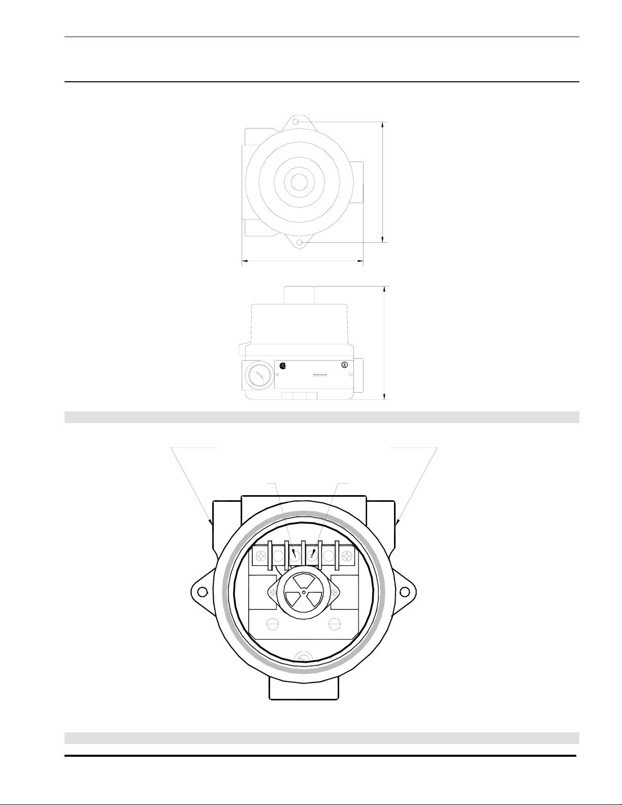
Figure 1 - Overall Dimensions
1/2" NPT CONDUIT ENTRANCES
TIP
RING
5.0" [128mm]
Figure 2 - Electrical Connections
Page 4
Page 5

Avaya Inc.
EA20R
TIP & RING
EA20R
JUNCTION
BOX
Installation and Operation
Model EA20R
TELEPHONE
TELEPHONE
TELEPHONE
EA20R
Figure 3 - Wiring Alternatives
Page 5
Page 6

Avaya Inc.
Installation and Operation
Installing the EA20R
Note: The EA20R must be connected to the tip and ring conductors
associated with the telephone for which the additional alerting signal
is required. The connection may be made either before or after the
telephone or it may branch off from a junction box.
• Declassify the hazardous location before proceeding with any
installation or electrical wiring.
WARNING
Do not connect this device to any power source other than telephone tip
and ring, doing so will destroy the circuitry and void the warranty.
• Follow all appropriate electrical codes and use only approved electrical
fittings for the installation.
• Choose a wall location that is free of obstructions and permits space for ½”
NPT conduit runs.
• Ensure mounting can support 5 lbs (2.3 kgs) and any additional anticipated
load.
• Ensure that none of the electrical connection circuits are live.
• Secure the unit using screws or bolts through the mounting tabs.
• Remove the screw cover.
• Run tip and ring wiring to the unit using appropriate electrical fittings.
• Attach the telephone tip and ring leads to the terminal strip.
• Replace the screw cover ensuring that the faces of the cover and the
enclosure are in contact.
• Apply power to the system.
• Test the unit by calling from another unit on the exchange.
Model EA20R
See: Figure 3 - Wiring
Alternatives
Caution: Installation or
electrical wiring in a
hazardous location
could result in serious
injury to personnel or
damage to property.
See: Figure 1 - Overall
Dimensions
Tip: Use #8 or M4
screws or equivalent
bolts to secure the unit to
the wall.
See: Figure 2 - Electrical
Connections
Maintenance
• Declassify the hazardous location or disconnect the line before
proceeding with any maintenance or repairs.
• To maintain hazardous area compliance the only field repair permitted is the
replacement of the driver assembly. All other repairs or alterations must be
carried out by Avaya or an Authorized Service Depot. See Warranty and
Disclaimer for details.
• When replacing the screw cover ensure that the faces of the cover and the
enclosure are in contact.
Page 6
Page 7

Avaya Inc.
Installation and Operation
Engineering Specifications
Electrical Performance
RINGER OUTPUT 85 +/- 3 dB
IMPEDANCE 600 OHMS NOMINAL
MAXIMUM LOOP 15,000 FT (4,500 M) of 22 AWG COPPER
RINGER EQUIVALENCE NUMBER (REN) 0.4A
Model EA20R
Electrical Requirements
RINGER SENSITIVITY 40 - 100 VAC, 16 - 25 HZ
CONNECTION METHOD TERMINAL BLOCK
Environmental
WEATHER AND CORROSION RESISTANT ENCLOSURE CSA 4X
TEMPERATURE -40
O
TO +60
O
C (-40
O
TO +140
O
F)
HUMIDITY 0 TO 95% RH NON-CONDENSING
Mechanical
BODY CONSTRUCTION COPPER FREE CAST ALUMINUM WITH EPOXY POWDER COAT
FLAME ARRESTOR SINTERED BRONZE
DIMENSIONS (H X W X D) 136 X 136 x 128 MM (5.4 X 5.4 X 5.0 INCHES)
NET WEIGHT 1.6 KG (3.5 LBS)
WIRING ACCESS ½ INCH NPT CONDUIT ENTRANCES
Compliance
CANADIAN STANDARDS ASSOCIATION (CSA) REFERENCE NUMBER: LR65547-31
EA20R CLASS I, DIVISION 1, GROUPS B, C AND D
C
LASS I, ZONE 1, GROUPS IIB+H2
LASS II, DIVISION 2, GROUPS F AND G
C
C
LASS III, HAZARDOUS LOCATIONS
T
EMPERATURE CODE T5
UNDERWRITERS LABORATORIES (UL) LISTED 66LN
CLASS I, DIVISION 1, GROUPS B, C AND D
CLASS I, ZONE 1, GROUPS IIB+H2
Page 7
Page 8

Avaya Inc.
Installation and Operation
Model EA20R
Warranty
Avaya warrants your product to be free of defects in material and workmanship for a period of one year.
Avaya will repair or replace any defective unit that is under warranty
This warranty is null and void if any non-authorized modifications have been made to this product, or if
it has been subjected to misuse, neglect, or accident. This warranty covers bench repairs only; such
repairs must be made at Avaya or an authorized service depot. Avaya is not responsible for costs
incurred for on-site service calls, freight, or brokerage.
A return authorization must be obtained prior to warranty claims or repairs.
Disclaimer
The products covered by this manual are designed for use in Industrial Environments and/or Hazardous
Locations. Due to the range of possible applications for these instruments the manufacturer will not be
responsible for damages or losses of any kind suffered as a result of the use of this product, including
consequential damages.
Warning
For the purposes of installing the product and performing maintenance or repairs this device may be
opened and reassembled by qualified personnel, following the instructions in the product manual. In
the cases of explosion proof and hazardous area devices it is imperative that mating surfaces be clean
and undamaged prior to reassembly and that fasteners be made up to the specified torque.
Service Telephone Number
Avaya provides a customer service telephone number which is toll-free within North America. If you
need assistance when installing or operating this product, please call the toll-free telephone number
between regular business hours (8:00AM-5:00PM), Eastern Standard Time. If you are calling outside of
regular business hours, please leave a detailed message, and a member of Avaya’s Service
Department will return your call as soon as possible. If your product requires service, Avaya personnel
will supply you with an RMA (return materials authorization) number over the telephone or through our
web site product return page. This number must be included with your return address and the name of
the person to contact.
Avaya Inc.
211 Mt. Airy Road
Basking Ridge, NJ 07920
Toll-free: 1-866-GOAVAYA (1-866-462-8292)
Outside the US: +1-908-953-6000
www.avaya.com
Page 8
Page 9

Avaya Inc.
Installation and Operation
Model EA20R
Avaya Product Return
Avaya products have been quality tested and are in full working order when shipped from the factory,
given the rugged nature of these products shipping is not expected to damage a unit. In the unlikely
event of a malfunction, Avaya follows the three step procedure below.
Step I - On-Site Correction
• The most common source of difficulties with a new product is improper installation in one of two
ways: incorrect wiring connections or connection to an incorrect power source.
• Product wiring needs to be properly connected to the on-site wiring. Correct wiring instructions are
shown in the user manual included with the product.
• Connecting this device to a standard power source, rather than tip & ring, will destroy the circuitry
and void the warranty.
Step II - Return Materials Authorization (RMA)
• When a product has been installed following user manual instructions, and the unit fails to
operate, the user must contact Avaya to obtain authorization to return the product. This can be
done by done by completing a RMA form online at www.Avaya.com, or by calling the service
telephone number given in this manual.
• After providing information on the product, the owner and the nature of the problem, Avaya will
issue a RMA number, to be shown on documentation returned with the product.
• In addition to the RMA number, shipping documents should include name, address and telephone
number of the owner along with contact information for the person responsible for the repair
and/or the user who identified the malfunction.
• (Where a product is being returned for repair from outside of USA, customs documentation must
show the product’s serial number, date of export [date of purchase], and a notation that the
equipment is: “USA goods returning.”)
Step III - Factory Authorized Service
• Once received, each product is carefully inspected and tested. If the product is under warranty,
repairs are completed and the product returned to the owner, generally within five working days of
receipt by the factory.
• A product that has been subjected to misuse, neglect or accident or is beyond the warranty period
will be evaluated. The service department will provide the owner’s representative with a repair cost
estimate. Once approved, repairs are completed and the product returned, generally within five
working days.
Page 9
Page 10

Avaya Inc.
Notes:
Model No.
Part No.
Serial No.
Date of Purchase
Installation and Operation
Model EA20R
Page 10
Page 11

Avaya Inc.
Installation and Operation
Model EA20R
Page 11
Page 12

Avaya Inc.
211 Mt. Airy Road
Basking Ridge, NJ 07920
Toll-free: 1-866-GOAVAYA (1-866-462-8292)
Outside the US: +1-908-953-6000
www.avaya.com
© Avaya Inc. 2003
 Loading...