

Avaya DECT R4, IP Office DECT R4, 3740, 3749 Installation Manual

15-601047 Issue 03a - (21 February 2011)
IP Office DECT R4 Installation
IP Office Release 7.0

DECT R4 Page 2
15-601047 Issue 03a (21 February 2011)IP Office Release 7.0
© 2011 AVAYA All Rights Reserved.
Notice
While reasonable efforts were made to ensure that the information in this document was complete and accurate at the time of
printing, Avaya Inc. can assume no liability for any errors. Changes and corrections to the information in this document may be
incorporated in future releases.
Documentation Disclaimer
Avaya Inc. is not responsible for any modifications, additions, or deletions to the original published version of this documentation
unless such modifications, additions, or deletions were performed by Avaya.
Link Disclaimer
Avaya Inc. is not responsible for the contents or reliability of any linked Web sites referenced elsewhere within this
Documentation, and Avaya does not necessarily endorse the products, services, or information described or offered within
them. We cannot guarantee that these links will work all of the time and we have no control over the availability of the linked
pages.
License
USE OR INSTALLATION OF THE PRODUCT INDICATES THE END USER’S ACCEPTANCE OF THE TERMS SET FORTH
HEREIN AND THE GENERAL LICENSE TERMS AVAILABLE ON THE AVAYA WEBSITE AT
http://support.avaya.com/LicenseInfo/ (“GENERAL LICENSE TERMS”). IF YOU DO NOT WISH TO BE BOUND BY THESE
TERMS, YOU MUST RETURN THE PRODUCT(S) TO THE POINT OF PURCHASE WITHIN TEN (10) DAYS OF DELIVERY
FOR A REFUND OR CREDIT.
Avaya grants End User a license within the scope of the license types described below. The applicable number of licenses and
units of capacity for which the license is granted will be one (1), unless a different number of licenses or units of capacity is
specified in the Documentation or other materials available to End User. “Designated Processor” means a single stand-alone
computing device. “Server” means a Designated Processor that hosts a software application to be accessed by multiple users.
“Software” means the computer programs in object code, originally licensed by Avaya and ultimately utilized by End User,
whether as stand-alone Products or pre-installed on Hardware. “Hardware” means the standard hardware Products, originally
sold by Avaya and ultimately utilized by End User.
License Type(s): Designated System(s) License (DS).
End User may install and use each copy of the Software on only one Designated Processor, unless a different number of
Designated Processors is indicated in the Documentation or other materials available to End User. Avaya may require the
Designated Processor(s) to be identified by type, serial number, feature key, location or other specific designation, or to be
provided by End User to Avaya through electronic means established by Avaya specifically for this purpose.
Copyright
Except where expressly stated otherwise, the Product is protected by copyright and other laws respecting proprietary rights.
Unauthorized reproduction, transfer, and or use can be a criminal, as well as a civil, offense under the applicable law.
Third-Party Components
Certain software programs or portions thereof included in the Product may contain software distributed under third party
agreements (“Third Party Components”), which may contain terms that expand or limit rights to use certain portions of the
Product (“Third Party Terms”). Information identifying Third Party Components and the Third Party Terms that apply to them is
available on Avaya’s web site at: http://support.avaya.com/ThirdPartyLicense/
Avaya Fraud Intervention
If you suspect that you are being victimized by toll fraud and you need technical assistance or support, call Technical Service
Center Toll Fraud Intervention Hotline at +1-800-643-2353 for the United States and Canada. Suspected security vulnerabilities
with Avaya Products should be reported to Avaya by sending mail to: securityalerts@avaya.com.
For additional support telephone numbers, see the Avaya Support web site (http://www.avaya.com/support).
Trademarks
Avaya and the Avaya logo are registered trademarks of Avaya Inc. in the United States of America and other jurisdictions.
Unless otherwise provided in this document, marks identified by “®,” “™” and “SM” are registered marks, trademarks and
service marks, respectively, of Avaya Inc. All other trademarks are the property of their respective owners.
Documentation information
For the most current versions of documentation, go to the Avaya Support web site (http://www.avaya.com/support) or the IP
Office Knowledge Base (http://marketingtools.avaya.com/knowledgebase/).
Avaya Support
Avaya provides a telephone number for you to use to report problems or to ask questions about your contact center. The
support telephone number is 1 800 628 2888 in the United States. For additional support telephone numbers, see the Avaya
Web site: http://www.avaya.com/support.

DECT R4 Page 3
15-601047 Issue 03a (21 February 2011)IP Office Release 7.0
Contents
Contents
DECT R41.
..................................................................... 81.1 Changes in IP Office Release 7.0
..................................................................... 91.2 Base Stations
..................................................................... 111.3 Aerials
..................................................................... 121.4 Phones
............................................................................ 121.4.1 3720
............................................................................ 131.4.2 3725
............................................................................ 141.4.3 3740
............................................................................ 151.4.4 3749
..................................................................... 161.5 Chargers
..................................................................... 171.6 AIWS
Site Survey and Planning2.
..................................................................... 212.1 Factors to Consider
..................................................................... 222.2 Handover
..................................................................... 232.3 Base Station Synchronization
..................................................................... 242.4 Performing a Survey
Provisioned Installation3.
..................................................................... 303.1 DECT Software
..................................................................... 313.2 IP Office Configuration
............................................................................ 323.2.1 Security Settings
............................................................................ 343.2.2 IP DECT Line Setup
............................................................................ 363.2.3 Adding Licenses
............................................................................ 383.2.4 Manually Creating Extensions
..................................................................... 393.3 Master Base Station Setup
............................................................................ 393.3.1 Defaulting the Base Station
............................................................................ 393.3.2 Determining the Base Station IP Address
............................................................................ 403.3.3 Access the Base Station Configuration
............................................................................ 413.3.4 Set the Base Station IP Address
............................................................................ 423.3.5 Update the Base Station Software
............................................................................ 443.3.6 Select Simplified Administration
............................................................................ 453.3.7 Set the DECT Password
............................................................................ 453.3.8 Select Master Mode
............................................................................ 473.3.9 Accept Devices
............................................................................ 483.3.10 Enable Provisioning
............................................................................ 493.3.11 Phonebook Integration
..................................................................... 493.4 Slave Base Station Setup
............................................................................ 503.4.1 Defaulting the Base Station
............................................................................ 503.4.2 Determining the Base Station IP Address
............................................................................ 513.4.3 Access the Base Station Configuration
............................................................................ 523.4.4 Set the Base Station IP Address
............................................................................ 533.4.5 Update the Base Station Software
............................................................................ 553.4.6 Register the Slave Base Station
..................................................................... 563.5 Base Station Mounting
..................................................................... 583.6 Phone Subscription
............................................................................ 593.6.1 Install Windows Device Manager
............................................................................ 603.6.2 Loading Parameter Definition Files
............................................................................ 633.6.3 Enabling Subscription
............................................................................ 643.6.4 Manually Creating Extensions
............................................................................ 653.6.5 Subscribing a Phone
............................................................................ 683.6.6 Upgrading Phones
............................................................................ 703.6.7 Disabling Subscription
............................................................................ 713.6.8 Displaying Subscribed Users
............................................................................ 723.6.9 Unsubscribing Phones
IP Office User Features4.
..................................................................... 744.1 Status Indicators
..................................................................... 754.2 Call Services
..................................................................... 774.3 In Call Options
..................................................................... 784.4 Call Waiting Options
Device Management5.
..................................................................... 815.1 Installing Windows Device Manager
..................................................................... 835.2 Starting AIWS Device Manager
..................................................................... 835.3 Starting Windows Device Manager
..................................................................... 845.4 Load Parameter Definition Files
..................................................................... 865.5 Loading Phone Templates into Device Manager
..................................................................... 885.6 Applying Templates to Phones
..................................................................... 905.7 Editing Templates
..................................................................... 925.8 Upgrading Phone Software
AIWS Installation6.
..................................................................... 986.1 Removing the AIWS Cover
..................................................................... 996.2 Connect the RTC Battery
..................................................................... 996.3 Cable Connections
..................................................................... 1006.4 Browse the AIWS
..................................................................... 1016.5 Run the Setup Wizard
..................................................................... 1076.6 Enable Base Station/AIWS Connection
..................................................................... 1086.7 Upgrade the AIWS Firmware
..................................................................... 1136.8 Switching Off the AIWS
..................................................................... 1136.9 Wall Mount the AIWS
..................................................................... 1146.10 Replace the AIWS Cover
..................................................................... 1146.11 AIWS Status Lamp
Miscellaneous7.
..................................................................... 1167.1 Base Station Reset Switch
..................................................................... 1167.2 Base Station Status Lamps
..................................................................... 1167.3 AIWS Status Lamp
Non-Provisioned Installation8.
..................................................................... 1218.1 DECT Software
..................................................................... 1228.2 Adding Licenses
............................................................................ 1228.2.1 Checking the Dongle Serial Number
............................................................................ 1228.2.2 Adding Licenses
............................................................................ 1238.2.3 Reserving Licenses
..................................................................... 1248.3 IP DECT Line Setup
..................................................................... 1268.4 Master Base Station Configuration
............................................................................ 1288.4.1 Default the Base Station
............................................................................ 1298.4.2 Access the Base Station's Configuration
............................................................................ 1308.4.3 Update the Base Station Firmware
............................................................................ 1328.4.4 Set the Base Station IP Address
............................................................................ 1338.4.5 Set the Time Source
............................................................................ 1348.4.6 QoS/ToS Settings
............................................................................ 1348.4.7 Enable Status Logging
............................................................................ 1358.4.8 Set the Base Station as the Master
............................................................................ 1378.4.9 Enable Supplementary Services
............................................................................ 1378.4.10 Set the PBX Switch Mode
............................................................................ 1388.4.11 IP Trunk Configuration
............................................................................ 1398.4.12 Enter the Radio Settings
............................................................................ 1398.4.13 Enter the PARI
............................................................................ 1408.4.14 Enter the SARI/PARK
............................................................................ 1408.4.15 Air Sync
............................................................................ 1418.4.16 IP Office Directory Integration

DECT R4 Page 4
15-601047 Issue 03a (21 February 2011)IP Office Release 7.0
............................................................................ 1428.4.17 Reset the Base Station
............................................................................ 1428.4.18 Check the Base Station
..................................................................... 1438.5 Slave Base Station Configuration
............................................................................ 1458.5.1 Default the Base Station
............................................................................ 1468.5.2 Access the Base Station's Configuration
............................................................................ 1478.5.3 Update the Base Station Firmware
............................................................................ 1498.5.4 Set the Base Station IP Address
............................................................................ 1508.5.5 Set the Base Station to Slave Mode
............................................................................ 1518.5.6 Reset the Base Station
............................................................................ 1528.5.7 Check the Base Stations
..................................................................... 1538.6 Base Station Mounting
..................................................................... 1558.7 Phone Subscription
............................................................................ 1568.7.1 Allow Subscription
............................................................................ 1588.7.2 Create User Entries
............................................................................ 1608.7.3 Phone Subscription
............................................................................ 1628.7.4 Completing Anonymous Login
............................................................................ 1638.7.5 Disable Subscription
Glossary9.
..................................................................... 1669.1 AIWS
..................................................................... 1669.2 IPBS
..................................................................... 1669.3 SS
..................................................................... 1669.4 SARI
..................................................................... 1669.5 PARI
..................................................................... 1669.6 PARK
..................................................................... 1669.7 FER
..................................................................... 1669.8 DECT
..................................................................... 1669.9 CAP
..................................................................... 1669.10 GAP
..................................................................... 1669.11 IPDI
..................................................................... 1669.12 IPEI
..................................................................... 1669.13 PBX
..................................................................... 1669.14 PDM
..................................................................... 1669.15 WSM
..................................................................... 1669.16 ELISE
..................................................................... 1669.17 SST
..................................................................... 1669.18 PP
..................................................................... 1679.19 RFP
..................................................................... 1679.20 RFPI
...............................................................................169Index

DECT R4 Page 5
15-601047 Issue 03a (21 February 2011)IP Office Release 7.0
DECT R4
Chapter 1.


DECT R4 Page 7
15-601047 Issue 03a (21 February 2011)IP Office Release 7.0
DECT R4:
1. DECT R4
Avaya DECT R4 is a DECT system where multiple base stations are connected using an IP LAN. For IP Office, DECT R4 is
supported with IP Office Release 5+. This installation manual covers the installation of DECT R4 systems using the
firmware supported by IP Office Release 7.0.
· IP DECT Base Station (IPBS)
Up to 32 are supported. During installation one is configured as the master base station, to which the other base
stations synchronize as slave base stations. Each base station can host up to 8 simultaneous phone conversations
in its coverage area.
· For IP Office Release 6 and higher, the Compact Base Station is supported. This type of base station only
supports 4 simultaneous calls. Up to 5 Compact Base Station units can be included in a system. If used as the
master base station, the whole system is limited to 5 base stations.
· Phones
Up to 120 DECT phones are supported. The Avaya 3700 Series phones supported are the 3720, 3725, 3740 and
3749. Other DECT phones, including the 3701 and 3711, are supported but only for basic telephony and only using
the DECT GAP and DECT CAP standards.
· Chargers
A number of different types of charger exist for 3700 Series phones. Note that chargers for 3720/3725 phones are
not necessarily useable with 3740/3749 phones.
· Basic Charger
This is a simple single-phone charger for charging only.
· Advanced Charger
This single-phone charger has USB and LAN sockets. These allow the phone docked with the charger to be
accessed using the Device Manager application (browser access via the AIWS unit and charger LAN port or
WinPDM application via the USB port).
· Rack Charger
This is an 6 phone advanced charger.
· Battery Rack Charger
This charger can be used to charge up to 6 batteries separate from the handsets.
· IP Office
DECT R4 is supported on IP Office systems running IP Office 5.0+ software. This manual is for systems running IP
Office Release 7.0 or higher in IP Office standard mode.
· Licenses
Each phone subscribed via the DECT R4 systems requires an Avaya IP Endpoint license in the IP Office
configuration.
· Configuration Tools
The tools and applications for DECT R4 are included as part of the IP Office Manager application installation. This
includes the appropriate firmware for operation with the IP Office system.
· Avaya In-Building Wireless Server (AIWS)
This unit allows SMS messaging between handsets. It also allows wireless software upgrades and configuration of
the handsets (without an AIWS, handsets can only be upgraded and configured when in an advanced charger). For
IP Office Release 5 this unit provides directory integration between the IP Office and the DECT R4 system. For IP
Office Release 6 directory integration can be done by the master base station but without SMS support. If both SMS
and directory integration are required then an AIWS unit must be used.
9
12
16
17

DECT R4 Page 8
15-601047 Issue 03a (21 February 2011)IP Office Release 7.0
1.1 Changes in IP Office Release 7.0
The following major changes have been made in the IP Office Release 7.0 support for DECT R4:
· Avaya 3740 and 3749 Telephones
These new phones in the 3700 Series are supported along with matching chargers and other accessories. The 3740
and 3749 are both ruggedized phones (IP65). The 3749 is also intrinsically safe for use in hazardous
environments.
· IP Office Provisioning
The DECT master base station can be installed in 'provisioning' mode. In this mode, once the base station is
operational and connected to the IP Office, the bulk of configuration is done by the IP Office.
· The IP Office is able to provide key settings to the base station such as the system SARI code and the
authentication code for phone subscription.
· User configuration and subscription control is done through the IP Office. Previously user configuration and
subscription was done in parallel through both the IP Office and base station.
· When using provisioning mode, 3700 Series handset are provided with enhanced menus and idle status display
driven by the IP Office. This does not include 3701, 3711 and other GAP compatible phones subscribed to the
system.
· When to Use IP Office Provisioning
IP Office provisioning both simplifies installation and maintenance and provides 3720, 3725, 3740 and 3749
phones with additional IP Office specific features. Therefore it is the recommended installation method for new
installations whenever possible.
· Provisioning installation in pre-configured or auto-create modes should be used for all installations with
just 3720, 3725, 3740 and 3749 phones.
· Provisioning installation in pre-configured mode should be used for all installations with a mix of 3720,
3725, 3740, 3749 phones and other DECT phones.
· Provisioning installation should not be used for installations with no 3720, 3725, 3740 or 3749 phones.
· Standard and Advanced Base Station Menu Modes
The base station configuration menus contain settings for a wide range of scenarios and interoperation with a
number of Avaya telephone systems. This can make installation both highly flexible but also make it seem
unnecessarily complicated. The menus can now be used in standard mode, with only key settings visible or
advanced mode with all settings visible. Note that compact base stations use standard mode by default.

DECT R4 Page 9
15-601047 Issue 03a (21 February 2011)IP Office Release 7.0
DECT R4: Changes in IP Office Release 7.0
1.2 Base Stations
DECT R4 supports three base station variants; the BS330, the Compact Base Station and the BS340. They differ in aerial
connection and in the number of simultaneous calls supported. During installation, one of the base stations is configured
as the master base station for the DECT R4 system. Any other base stations are configured as slave base stations.
Each base station includes a detachable bracket for use in wall mounting of the base station. Each base station requires a
LAN access point and is supplied with a 1.2 metre (4 foot) LAN cable.
Each base station can be powered using IEEE 802.3af power over ethernet (PoE 7W Class 2). Alternatively the base
station also requires a main power supply outlet socket within 8 metres (26 feet) cable distance and power supply unit.
· BS330
The BS330 has 2 integral internal aerials which cannot be adjusted. The aerials produce a slightly directional
pattern of radio coverage. The base station supports up to 8 simultaneous calls.
· Compact Base Station
The Compact Base Station is physically the same as the BS330 but only supports 4 simultaneous calls. Up to 5
Compact Base Station units can be included in a system. If used as the master base station, the whole system
is limited to 5 base stations. Compact Base Station are only supported if all the other base stations are running
firmware version 3.3.11 or later.
· BS340
The BS340 has 2 external aerials. These aerials produce an even pattern of radio coverage. The base station
supports up to 8 simultaneous calls. The aerials can be disconnected and replaced by a various other types of
aerials if different radio coverage patterns and range is required. This type of base station in not supported in
North America.
The base stations include a detachable bracket for use for wall mounting or column mounting of the base station. This also
allows the base stations to be removed for maintenance.
11
DECT R4 Page 10
15-601047 Issue 03a (21 February 2011)IP Office Release 7.0
Base Station Details
Feature
Details
DECT Frequencies
Brazil
1910-1920 MHz frequencies.
Latin America
1910-1930 MHz frequencies.
North America
1920-1930 MHz frequencies.
Rest of World
1880-1900 MHz frequencies.
Physical
Dimensions
(Height × Width × Depth)
165 × 200 × 56 mm (including mounting bracket).
Add 95mm height for external aerials.
Weight
450g
Material
ABS moulded plastic
Colour
Beige
External connectors
2 × RJ45, 1 x RJ12
Power
Input
Power over Ethernet IEEE 802.3af or local power supply
Operating voltage
21 to 56 V dc.
Power consumption
Typical 4W, maximum 5W.
Power over Ethernet
PoE Class 2 (7W).
Network
Ethernet:
10/100baseT
Voice over IP
H.323 XMobile incl. QSig/DSS1.
Voice Encoding
G.711 A-law / µ-law (64kbps)
G.723.1 (5.3 kbps)
G.729A and AB (16 kbps)
Radio
RF output power EU
Between 23 dBm and 28 dBm (with internal antenna)
Between 20 dBm and 25 dBm (with external antenna)
RF output power US
Between 17 dBm and 21,6 dBm (with internal antenna)
Environmental
Operating temperature
-10°C to +55°C
Storage temperature
-40°C to +70°C
Relative operating humidity
15 to 90%, non condensing
Relative storage humidity
5 to 95%, non condensing
Immunity to electromagnetic fields
3V/m (EN61000-4-3)
Immunity to ESD
4 kV contact discharge and 8 kV air discharge
(EN61000-4-2)

DECT R4 Page 11
15-601047 Issue 03a (21 February 2011)IP Office Release 7.0
DECT R4: Base Stations
1.3 Aerials
The following different aerials can be used to replace the aerials on a BS340 base station. These aerials have aerial leads
to allow for optimal positioning. Note that this type of base station and therefore optional aerials are not supported in
North America.
· Omni-Directional Single Aerial
A pair of these aerials can be used to approximately double the base station radio coverage, ie. up to 600 metres
(2000 feet) omni-directional coverage.
· Directional Dual Aerial
This aerial gives directional coverage up to 750 metres (2500 feet). Only one aerial unit is required for connection
to the base station.
· Directional Single Antenna
A pair of these aerials can be used to give directional coverage up to 1000 metres (3300 feet). They must be
mounted facing the same direction and approximately 1 metre (3 feet) apart. To achieve maximum coverage, the
aerial should be mounted between 4 to 8 metres (13 to 26 feet) above area being covered.

DECT R4 Page 12
15-601047 Issue 03a (21 February 2011)IP Office Release 7.0
1.4 Phones
The following Avaya 3700 Series phones are supported by DECT R4.
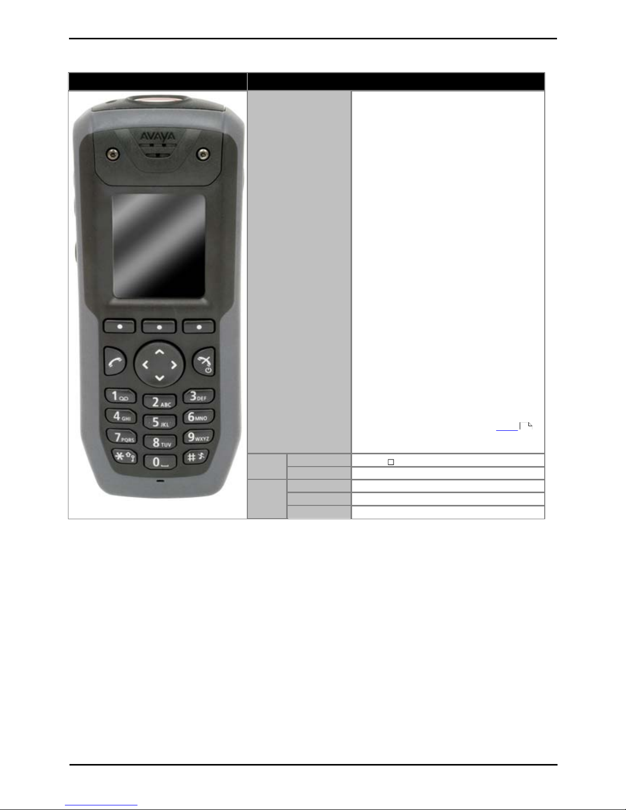
1.4.1 3720
Avaya 3720
Description
Features
· High quality voice DECT phone, GAP/CAP
compliant.
· Easy access to PBX services.
· Voicemail including message icon.
· Manual and automatic keypad lock.
· Local directory: 250 entries.
· Central directory from the IP Office.
· Call list with the 25 last calls.
· Vibrator.
· Loudspeaker/hands free.
· Central Management and software download.
· Headset socket (2.5mm).
· 5 languages*
English, German, Spanish, French. One additional
language can be uploaded.
· Monochrome display (112 x 115 pixels).
· GAP compatible.
Physical
Dimension
133 x 53 x 24mm
Weight
115g
Battery
Type
600 mAh, Lithium 3.7V. Charge time 4 hours.
Speech Time
> 16 hours.
Standby Time
> 160 hours.
· *For systems installed using IP Office provisioning, the language used is set by the IP Office system or user
language setting.
· An additional language file can be uploaded to a phone.

DECT R4 Page 13
15-601047 Issue 03a (21 February 2011)IP Office Release 7.0
DECT R4: Phones
1.4.2 3725
Avaya 3725
Description
Features
· As per 3725 plus:
· Site Survey tool.
· Cleanable, IP 44.
· Option: Bluetooth.
· 19 Languages
Czech, Danish, Dutch, English, Finnish, French,
German, Greek, Hungarian, Italian, Norwegian,
Polish, Portuguese (Brazilian), Portuguese,
Russian, Slovakian, Spanish, Swedish and
Turkish.
· Colour display (128 x 160 pixels).
· SMS
Message length up to 160 characters. 30
received/sent messages. Requires AIWS
.
· GAP compatible.
Physical
Dimension
134 x 53 x 26mm
Weight
130g
Battery
Type
930 mAh, Li-Pol 3.7V. Charge time 4 hours.
Speech Time
> 20 hours (13h with Bluetooth option)
Standby Time
> 120 hours.
· *For systems installed using IP Office provisioning, the language used is set by the IP Office system or user
language setting.
· An additional language file can be uploaded to a phone.
96
DECT R4 Page 14
15-601047 Issue 03a (21 February 2011)IP Office Release 7.0
1.4.3 3740
Avaya 3740
Description
Features
· High quality voice DECT phone, GAP/CAP
compliant
· Easy access to PBX services
· Voicemail including message icon.
· Manual and automatic keypad lock
· Local directory: 250 entries.
· Central directory from the IP Office.
· Call list with the 25 last calls
· Vibrator
· Loudspeaker/hands free
· Central Management and software download
· Headset socket (IP65 plug).
· 19 Languages
Czech, Danish, Dutch, English, Finnish,
French, German, Greek, Hungarian, Italian,
Norwegian, Polish, Portuguese (Brazilian),
Portuguese, Russian, Slovakian, Spanish,
Swedish and Turkish.
· Ruggedized.
· IP65 Classified.
· Wide temperature range: -10C to 55C.
· Monochrome display (128 x 160 pixels).
· SMS
Message length up to 160 characters. 30
received/sent messages. Requires AIWS
.
· GAP compatible.
Physical
Dimension
143 x 59 x 29mm
Weight
180g
Battery
Type
920 mAh, Li-lon 3.7V. Charge time 4 hours.
Speech Time
> 18 hours.
Standby Time
> 150 hours.
· *For systems installed using IP Office provisioning, the language used is set by the IP Office system or user
language setting.
· An additional language file can be uploaded to a phone.
96

DECT R4 Page 15
15-601047 Issue 03a (21 February 2011)IP Office Release 7.0
DECT R4: Phones
1.4.4 3749
Avaya 3749
Description
Features
· High quality voice DECT phone, GAP/CAP
compliant
· Easy access to PBX services
· Voicemail including message icon.
· Manual and automatic keypad lock
· Local directory: 250 entries.
· Central directory from the IP Office.
· Call list with the 25 last calls
· Vibrator
· Option: Bluetooth.
· Loudspeaker/hands free
· Central Management and software
download
· Headset socket (IP65 plug).
· 19 Languages
Czech, Danish, Dutch, English, Finnish,
French, German, Greek, Hungarian,
Italian, Norwegian, Polish, Portuguese
(Brazilian), Portuguese, Russian,
Slovakian, Spanish, Swedish and Turkish.
· Ruggedized.
· IP65 Classified.
· Intrinsically Safe. Conforms to
ATEX/IECEx
· Wide temperature range: -10C to 55C.
· Colour display (128 x 160 pixels).
· SMS
Message length up to 160 characters. 30
received/sent messages. Requires AIWS
.
· GAP compatible.
Physica
l
Dimension
143 x 59 x 29mm
Weight
180g
Battery
Type
920 mAh, Li-lon 3.7V. Charge time 4 hours.
Speech Time
> 10 hours.
Standby
Time
> 80 hours.
· Due to the power restrictions for intrinsically safe handset operation, the display brightness is lower, the
loudspeaker and ringer volumes are lower and the audible ringer and vibrating alert cannot be activated
simultaneously.
· *For systems installed using IP Office provisioning, the language used is set by the IP Office system or user
language setting.
· An additional language file can be uploaded to a phone.
96

DECT R4 Page 16
15-601047 Issue 03a (21 February 2011)IP Office Release 7.0
1.5 Chargers
A number of different types of charger exist for 3700 Series phones. Note that chargers for 3720/3725 phones are not
useable with 3740/3749 phones and vice versa.
· Basic Chargers
These are simple single-phone charger for charging only. The basic charger for 3720/3725 phones is not usable
with 3740/3749 phones and vice versa.
· Advanced Chargers
These are single-phone chargers with USB and LAN sockets. These allow the phone docked with the charger to be
accessed using the Device Manager application (browser access via the AIWS unit and charger LAN port or WinPDM
PC application access via the USB port). The advanced charger for 3720/3725 phones is not usable with 3740/3749
phones and vice versa.
· Rack Chargers
These are 6 phone advanced chargers. The rack charger for 3720/3725 phones is not usable with 3740/3749
phones and vice versa.
· Battery Chargers
These chargers allows the charging of up to 6 batteries separate from the phones. The battery charger for
3720/3725 phones is not usable with 3740/3749 phones and vice versa. There is no battery charger for 3749
phones.

DECT R4 Page 17
15-601047 Issue 03a (21 February 2011)IP Office Release 7.0
DECT R4: Chargers
1.6 AIWS
The AIWS (Avaya In-Built Wireless Server) unit allows SMS messaging between handsets. It also allows wireless software
upgrades and configuration of the handsets. Without an AIWS, handsets can only be upgraded and configured when in an
advanced charger.
For IP Office Release 5 this unit also provides directory integration between the IP Office and the DECT R4 system. For IP
Office Release 6 and higher, directory integration is done by the master base station without requiring an AIWS. However
an AIWS is still required for both SMS.
The unit is managed via web browser and requires a fixed IP address.
· Wall mountable.
· Dimensions: 275 x 130 x 60 mm, 550g.
· Supplied with power supply unit and power cords.

DECT R4 Page 18
15-601047 Issue 03a (21 February 2011)IP Office Release 7.0

DECT R4 Page 19
15-601047 Issue 03a (21 February 2011)IP Office Release 7.0
Site Survey and Planning
Chapter 2.

DECT R4 Page 20
15-601047 Issue 03a (21 February 2011)IP Office Release 7.0
2. Site Survey and Planning
We cannot give precise recommendations for a site survey as every site will vary. However a site survey is a prerequisite
to installation in all cases. The correct and effective placement of base stations will prevent problems and maximize
coverage. Most issues with any DECT system will arise from the number and positioning of the base stations.
The basic aim is to ensure:
· Base station coverage in all areas of expected DECT phone usage.
· Sufficient number of base stations covering each area for the number of expected simultaneous users (up to 8 per
base station) in that area.
· Sufficient overlap between areas of base station coverage to allow for call handover when DECT phone users
are moving.
· Where possible, synchronization of each base station with more than one other base station.
The diagram below indicates the basic measures for coverage between a base station and a DECT phone.
Signal
Strength
Description
-40dB
Strong signal typically seen when a phone is close to the base station.
-62dB
Minimum signal strength at which a base station will accept a phone wanting to handover from another base
station.
-68dB
Signal strength below which the phone will begin looking for a base station to which it can handover.
-75dB
At this signal strength, the increase error rate will become apparent in the speech.
-90dB
At this signal strength calls are likely to disconnect.
Though this section focuses mainly on the measure of signal strength, the DECT signalling employs a number of methods
to overcome a poor signal. The other key factor that affects signalling is the error rate. While decreasing signal strength
and increasing error rate are usually related, there may be some scenarios where a high than expect error rate occurs.
22
23

DECT R4 Page 21
15-601047 Issue 03a (21 February 2011)IP Office Release 7.0
Site Survey and Planning: Factors to Consider
2.1 Factors to Consider
Given ideal open field conditions, the range between a phone and a standard base station can be up to 600 metres (2000
feet). However where obstacles absorb signal strength and reflected signals giving increased error rates, the range is more
realistically between 30 metres (100 feet) indoors and 300 metres (1000 feet) outdoors.
In practice, no rules or guarantees can be given for base station coverage. Coverage is affected by too many factors that
are unique to each site. The following is a guide to those factors that can affect coverage which you should consider and
look for during any site survey.
· Obvious causes of signals problems
· Metal surfaces.
· Concrete thickness greater than 1 metre (3 feet).
· Also beware of
· Windows with Reflective Film or Specialized Glass.
These produce increased signal reflection and reduced signal pass-through.
· Wire Meshes and Grills with Apertures of Less than 4cm (1.5 inches).
These block signals as effectively as continuous metal sheet.
· Fire Doors
These block the signals. In multi-occupancy building such as hotels, the high number of fire-doors may be a
problem.
· Stair Wells
In modern office buildings, stair wells frequently combine concrete building supports, fire doors and the
intervening floor material, making them a special problem.
· Screened Rooms
Typically found in offices involved with TV, video and radio production, but also possible in computer centers.
· Empty Sites
Do not perform a survey on a site that is not yet occupied. The survey results will differ from those of the same
site once occupied by the customer business. Similarly the survey should be performed during normal business
hours in order to assess the areas of usage and the effect of equipment being operated and moved.
· Be aware of
· Signal Direction
The signal from a base station does not propagate evenly in all directions. The signal typically propagates
strongest in the horizontal plane. However the ability for a base station to serve callers located on floors above
or below it should not be ignored. This may allow coverage to be extended to areas not frequently used and so
not meriting a dedicated local base station.
· Other Radio Signals
The ability to receive normal broadcast radio signals in an area is not an indication that DECT signaling will be
received and vice versa.
· Rack Chargers
A rack charger (6 phones) immediately creates an area where a single base station (8 calls) would be near
maximum capacity. Look to provide overlapping base station support to areas where rack chargers will be
located.

DECT R4 Page 22
15-601047 Issue 03a (21 February 2011)IP Office Release 7.0
2.2 Handover
Once a phone is connected on a call through a particular base station, it will normally maintain connection with that base
station even if the phone moves into an area with a stronger signal from another base station. However, when the signal
to the phone drops below -68dB, the phone will begin looking for another base station with a better signal to which it can
handover (this is often referred to as "roaming"). If the other base station signal is -62dB or higher, the phone will
handover to that base station if it has free capacity.

DECT R4 Page 23
15-601047 Issue 03a (21 February 2011)IP Office Release 7.0
Site Survey and Planning: Handover
2.3 Base Station Synchronization
Base stations in the DECT R4 system need to be synchronized with each other. This can be done with a signal as low as 90dB between base stations.
One base station is assigned as the 'air synch master', typically the master base station. Each other base station can
synch directly with it or indirectly via a synchronization chain. However, it is preferable that the number of synchronization
'hops' between any particular base station and its air synch master base station is kept as low as possible. To help achieve
this it is recommended that the air synch master is placed centrally within the set of base stations.
Where possible, each base station should be placed in synchronization range of more than one base station. That allows
the base stations to maintain synchronization should one base station fail or be switched off for maintenance. The process
of synchronizing by the shortest route to the air synch master when in synchronization range of multiple base stations is
automatic.
Advanced Scenario: Separated Locations
In most scenarios, the master base station is used as the air synch master for all the other base stations and that is the
scenario documented in this manual. However, in scenarios where you have base stations in separate locations that are
not within synchronization range of each other, it is permissible to assign separate air synch masters in each location.
However there must be absolutely no overlap (<-90dB) between the separate groups of base stations. Any overlap will
cause frequent lose of synchronization.

DECT R4 Page 24
15-601047 Issue 03a (21 February 2011)IP Office Release 7.0
2.4 Performing a Survey
· While performing a survey you will require the following information:
· Building Layout
Accurate building plans are an essential aid to both the site survey and also for later fault analysis. Ensure that
you have an accurate plan of the customer premises, including the locations of mains power outlets and
network connection points.
· The area of coverage required?
Which areas within the plans the customer expects to be covered. Do they expect coverage outside the building
and or in buildings separate from the main building.
· The number of simultaneous users within different areas?
Each base station can support up to 8 simultaneous calls (4 for a Compact Base Station).
· Perform the survey during normal business hours. The movement of large items of machinery, such as lifts and
shutter doors, will then be observable during the survey.
· Ensure that you have read this documentation and understand the requirement of both phone handover and
base station synchronization .
· As the survey takes place, note whether additional network connection points will be required and or mains power
outlets. Consider the use of Power over Ethernet, if possible in order to simplify base station installation.
22
23

DECT R4 Page 25
15-601047 Issue 03a (21 February 2011)IP Office Release 7.0
Site Survey and Planning: Performing a Survey
Site Survey Mode
The following method is used to put a subscribed phone into site survey mode.
1.
Go to the Call Time menu (Menu | Calls | Call Time).
2.
Activate the Admin menu by pressing * * .
3.
In Admin menu, select DECT Info.
4.
Select Link. The phone will display information about the base station.
· C7 S10
This is the DECT signal carrier and slot.
· ss
This is the signal strength . This is the main value that should be recorded and accessed as you perform the
survey.
Signal
Strength
Description
-40dB
Strong signal typically seen when a phone is close to the base station.
-62dB
Minimum signal strength at which a base station will accept a phone wanting to handover from another base
station.
-68dB
Signal strength below which the phone will begin looking for a base station to which it can handover.
-75dB
At this signal strength, the increase error rate will become apparent in the speech.
-90dB
At this signal strength calls are likely to disconnect.
· Error rate / Q2 Error rate
These are the error (corrupted) frames per second on the signals from and to the base station.
· PARI
The PARI of the DECT system.
· Bear:
The current power output of the phone.
· Pwr = on hook
· LU = off hook, Low power
· US = off hook, Normal power
· EU = off hook, High power
20


DECT R4 Page 27
15-601047 Issue 03a (21 February 2011)IP Office Release 7.0
Provisioned Installation
Chapter 3.

DECT R4 Page 28
15-601047 Issue 03a (21 February 2011)IP Office Release 7.0
3. Provisioned Installation
A provisioned install is the recommended method for both installation simplicity and handset feature support. It should be
used for all installations using just Avaya 3700 Series phones.
· When to Use IP Office Provisioning
IP Office provisioning both simplifies installation and maintenance and provides 3720, 3725, 3740 and 3749
phones with additional IP Office specific features. Therefore it is the recommended installation method for new
installations whenever possible.
· Provisioning installation in pre-configured or auto-create modes should be used for all installations with
just 3720, 3725, 3740 and 3749 phones.
· Provisioning installation in pre-configured mode should be used for all installations with a mix of 3720,
3725, 3740, 3749 phones and other DECT phones.
· Provisioning installation should not be used for installations with no 3720, 3725, 3740 or 3749 phones.
1.
Unpack the latest IP DECT software .
2.
Configure the IP Office for provisioned operation .
3.
Configure the Master Base Station .
4.
Configure the Slave Base Stations .
5.
Base Station Mounting .
6.
Phone Subscription .
The installation process used here is only an example. Other methods and order can be used once you become familiar
with the installation process. For example, installing all the slave base stations before installing the master base station.
IP Office Installation Requirements
· It is assumed that you are familiar with installation and configuration of IP Office systems.
Information
· Service user name and password for IP Office configuration access.
· Service user name and password for IP Office security settings access.
· IP Office IP address.
· Avaya IP Endpoint licenses
Parts Required
· IP Office Release 7.0 software DVD or image of the IP Office Release 7.0 admin software.
Tools Required
· Programming PC with IP Office Manager application installed. You must have rights on this PC to change its IP
address settings unless it is a DHCP client.
· Software for zip file extraction.
30
31
39
49
56
58

DECT R4 Page 29
15-601047 Issue 03a (21 February 2011)IP Office Release 7.0
Provisioned Installation:
Base Station Installation Requirements
Parts Required
· Base station
Includes:
· Base station.
· Two 3.5mm screws and two 6mm wall plugs suitable for wall mounting onto a solid wall (brick or similar).
· 1.2 metre (4 foot) LAN cable. If this is replaced with a longer cable the replacement should be a CAT5 Ethernet
LAN cable.
· If using Power over Ethernet:
· The base station supports Power over Ethernet, IEEE 802.3af, class 2.
· If not using Power over Ethernet:
· Base station power supply unit.
Required if not using Power over Ethernet to power the base station. Note that the base station power supply
units include an 8 metre (26 feet) cable from the PSU to the base station. Check that you have the correct type
of power supply unit for the locale.
· BSX-0013: Europe (except United Kingdom).
· BSX-0014: United Kingdom.
· BSX-0015: USA/Canada.
· BSX-0016: Australia.
· Mains power outlet socket.
· LAN Socket.
Information
· DECT R4 SARI.
· Base Station IP Addresses.
· Detailed plans from the site survey indicating the intended base station locations, LAN sockets and if necessary
power supply outlets.
Tools
· Programming PC with DECT R4 software.
· Web browser.
· Drill and drill bits suitable for the selected wall mounting position of the AIWS.
· Screwdrivers for use with the screws selected for AIWS wall mounting.
Phone Subscription Requirements
Information
· Service user name and password for IP Office configuration.
· User names and extension numbers for the DECT phones.
· Phone IPEI numbers if using an pre-configured installation mode.
Tools
· IP Office Manager.
· Device Manager
The software installed on each handset may need to be upgraded to match that supplied with the DECT R4 software
. This is done using the Windows Device Manager software to upgrade phones via an advanced charger or
using AIWS Device Manager to upgrade phones over the air.
· Web browser (Internet Explorer or Firefox are supported).
30
83
DECT R4 Page 30
15-601047 Issue 03a (21 February 2011)IP Office Release 7.0
3.1 DECT Software
Before beginning installation, in addition to having IP Office Manager installed, you need to unpack the DECT R4 software
onto your programming PC.
DECT R4 is supported on a range of Avaya systems. However, for IP Office operation, only firmware specifically
documented as having been tested and supported with IP Office should be used. Details of supported firmware will be
included in IP Office Technical Bulletins and Technical Tips.
1.
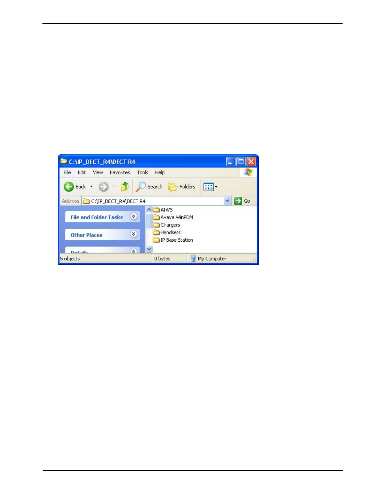
On the programming PC, create a folder with a name indicating its purpose, for example c:\IP_DECT_R4.
2.
Within the IP Office Administrator Application software (ie. the software from which IP Office Manager is installed),
locate the folder IPDECT.
3.
The folder contains a file DECT R4.zip. This is the file containing software for DECT R4. The file IPDECT.zip
contains software for the previously supported IP DECT product and not for DECT R4.
4.
Copy the DECT R4.zip file to the folder created on the programming PC.
5.
Using WinZip or a similar tool, extract the contents of the zip file into the folder, maintaining the directory structure
of the zip files.
6.
The set of files should appear similar to the following.
7.
Open the IP Base Station folder and note the software level shown as part of the .bin file filenames. All the base
station in the installed system should be run the same levels of software.
8.
Open the Handsets folder and note the software level shown as part of the .pkg file filenames. The handsets in the
system should be running this level of software or higher.
Device Management
During installation (provision or non-provisioned) it may be necessary to upgrade the software being used by the 3720,
3725, 3740 or 3749 phones. This is done in one of two ways:
· Windows Device Manager
The Windows device manager application can be used to upgrade the software of phones placed in an advanced
charger and connected to the PC via USB or LAN. If using this method, install the Windows Device Manager
software and load the parameter definition files supplied with the DECT R4 software.
· AIWS Device Management
The AIWS device includes an integrated version of device manager that can be used to perform over the air
upgrades. This method is only recommended for the maintenance of an existing system. For upgrades during
installation of a new system, the use of Windows Device Manager is recommended.
 Loading...