

Page 1

Nortel Communication Server 1000
DECT Messenger
Fundamentals
Release: 6.0
Document Revision: 02.01
www.nortel.com
NN43120-120
.
Page 2

Nortel Communication Server 1000
Release: 6.0
Publication: NN43120-120
Document release date: 11 May 2009
Copyright © 2003-2009 Nortel Networks
All Rights Reserved.
Sourced in Canada
LEGAL NOTICE
While the information in this document is believed to be accurate and reliable, except as otherwise expressly
agreed to in writing NORTEL PROVIDES THIS DOCUMENT "AS IS "WITHOUT WARRANTY OR CONDITION OF
ANY KIND, EITHER EXPRESS OR IMPLIED. The information and/or products described in this document are
subject to change without notice.
Nortel, the Nortel logo, Nortel Networks, DMS, and the Globemark are trademarks of Nortel Networks.
All other trademarks are the property of their respective owners.
.
Page 3

.
Contents
New in this release 7
Features 7
Other changes 7
Nortel DECT Messenger Administrator Guide 9
Preface 9
Nortel DECT Messenger overview 10
eCONFIG 18
Adding a DECT device to the Messenger system 51
DECT Messenger Customer Engineer Manual 57
Preface 58
DECT Messenger overview 60
DECT Messenger in a WAN or MAN network 68
Licensing 69
Detailed module descriptions 73
3
About the manual 58
Guidelines for maintenance and administration of a server or specialized
computer 58
Nortel DECT Messenger functional description 60
Modules overview 62
Linking modules 65
CSTA connection (link) license 69
SOPHO CTI module License Manager licenses 72
eKERNEL 74
eDMSAPI 74
eIO 75
eSMTP 75
eSMTP_Server 75
eAPI 76
eWEB 76
eCONFIG 78
eGRID 78
eTM 78
eLOG 78
Copyright © 2003-2009 Nortel Networks
.
Nortel Communication Server 1000
DECT Messenger Fundamentals
NN43120-120 02.01
11 May 2009
Page 4

4
eCAP 79
eESPA 79
eLOCATION 79
eSMS 79
eSNMP 79
eFR 79
Web administrator 80
What is required to run DECT Messenger 81
Hardware Requirements 81
Software Requirements 81
DMC Configuration 82
DATABASES in DECT Messenger 84
Supported Database types 84
How to set up the Databases 85
Installing and getting started 85
Stopping IIS WEB Services 85
Installing DECT Messenger 87
Getting Started 88
Using eCONFIG 95
Using eCONFIG (Local) on the DECT Messenger Server PC 96
Using eCONFIG (Remote) on remote PC (client) in the Network 97
Using eTM 98
eDMSAPI Inbound 99
Incoming Alarm (IA) from DMC 100
Incoming Alarm (IA) from IP DECT 101
Incoming Confirmation (IC) 101
Parameters required to set an alarm 102
SET/RESET structure 108
eLOCATION 113
How it works 114
eLOCATION Module in eCONFIG 115
Connecting National Instruments modules 116
General 116
Hardware Installation 120
Software Installation 120
Understanding Security features 126
Session Guarding 126
Watchdog 126
Using eBackup 133
Setting up e-mail integration (eSMTP_Server/eSMTP) 137
General 137
Using eSMTP Server 138
How eSMTP Works 138
Installing IIS 141
Copyright © 2003-2009 Nortel Networks
.
Nortel Communication Server 1000
DECT Messenger Fundamentals
NN43120-120 02.01
11 May 2009
Page 5

Configuring eSMTP_Server in eConfig 142
Configuring IIS for DECT Messenger 142
Using eSMTP 146
Sending SMS messages 147
eSMTP 147
eASYNC 147
V.24 - RS232 connections (eCAP, eESPA) 150
eCAP 151
eESPA 151
Using Import/Export menu 152
eLOG 153
“” (page 156) 156
OUTrqs.csv file 159
“” (page 161) 161
How to use the Files 164
Checking diagnostics 165
General 165
Logging 165
Module Window 169
eKERNEL Window 173
Simulation Options in a Module 174
eKERNEL Service Options 174
5
Copyright © 2003-2009 Nortel Networks
.
Nortel Communication Server 1000
DECT Messenger Fundamentals
NN43120-120 02.01
11 May 2009
Page 6

6
Copyright © 2003-2009 Nortel Networks
.
Nortel Communication Server 1000
DECT Messenger Fundamentals
NN43120-120 02.01
11 May 2009
Page 7

.
New in this release
Features
There are no new features introduced with this release.
Other changes
For a detailed history of past releases of this document, see Table 1
"Revision history" (page 7).
Table 1
Revision history
May 2009 Standard 02.01. This document is up-issued to
support Communication Server 1000 Release
6.0.
October 2008 Standard 01.06 This document is up-issued
to support Nortel Communication Server
1000 Release 5.5, and contains additional
changes relating to updates in Release 4 of the
Messenger software.
7
September 2008 Standard 01.02. This document is up-issued
to support Nortel Communication Server 1000
Release 5.5, and contains changes relating to
updates to the Messenger software.
May 2008 Standard 01.01 This document is issued to
support Nortel Communication Server 1000
Release 5.5. Some of the information in
this new document was previously in DECT
Fundamentals (NN43120-114).
Nortel Communication Server 1000
DECT Messenger Fundamentals
NN43120-120 02.01
Copyright © 2003-2009 Nortel Networks
11 May 2009
.
Page 8

8 New in this release
Copyright © 2003-2009 Nortel Networks
.
Nortel Communication Server 1000
DECT Messenger Fundamentals
NN43120-120 02.01
11 May 2009
Page 9

.
Nortel DECT Messenger Administrator
Guide
This chapter contains information on the following topics:
•
“Nortel DECT Messenger overview” (page 10)
—
“What is Nortel DECT Messenger” (page 10)
—
“Modules overview” (page 12)
—
“eCONFIG basic concepts” (page 14)
—
“DECT Messenger concepts” (page 16)
• “eCONFIG” (page 18) eCONFIG Section
—
“Opening the eCONFIG” (page 18)
—
“eCONFIG main window” (page 20)
— “Managing devices” (page 23)
—
“Managing groups” (page 32)
9
—
“Managing group members” (page 39)
—
“Managing users” (page 45)
•
“Adding a DECT device to the Messenger system” (page 51)
Preface
This chapter contains an overview of Nortel DECT Messenger in general,
and information for users of the eCONFIG module specifically. It contains
important information on the underlying structure of the eCONFIG module,
and on creating, deleting, and making changes to Users, Devices, and
Groups.
This chapter does not cover all of the menus and associated menu
items that are available in the eCONFIG module. Menus and associated
menu items that are not covered require detailed technical background
knowledge.
Copyright © 2003-2009 Nortel Networks
Nortel Communication Server 1000
DECT Messenger Fundamentals
NN43120-120 02.01
11 May 2009
.
Page 10
10 Nortel DECT Messenger Administrator Guide
For information about the other menu parameters in the eCONFIG module,
or information for any of the other modules in Nortel DECT Messenger,
refer to
DECT Messenger Installation and Commissioning (NN43120-301).
Nortel DECT Messenger overview
DECT Messenger provides a software tool, the eCONFIG, for making
changes to the configuration. The eCONFIG is on either the same PC as
the DECT Messenger software, or on another PC in the TCP/IP network.
After you run eCONFIG on another PC, the number of items you can
change is limited.
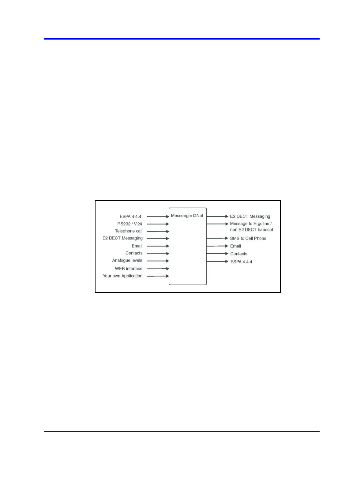
What is Nortel DECT Messenger
DECT Messenger is a software platform that allows message generation,
message routing, and message protocol conversion. Figure 1 "Nortel
DECT Messenger" (page 10) shows the inputs and outputs of DECT
Messenger.
Figure 1
Nortel DECT Messenger
Message input
The following input can generate messages in DECT Messenger:
• ESPA 4.4.4 pager protocol: DECT Messenger can receive pager
messages from ESPA 4.4.4-compatible pager equipment.
• RS232/V.24 serial input: many protocols are supported as input for
generating a predefined message or a user defined message.
• DECT handset with E2 (Low Rate Messaging Services [LMRS])
messaging.
• E-mail to the DECT Messenger server PC: send a message from
e-mail to a telephone set or SMS to cell phone or any other output on
DECT Messenger.
• Switches (push button, toggle): message alerts generated by alarm
contacts, door contacts, fire contacts, and so on.
Copyright © 2003-2009 Nortel Networks
.
Nortel Communication Server 1000
DECT Messenger Fundamentals
NN43120-120 02.01
11 May 2009
Page 11

Nortel DECT Messenger overview 11
• Analogue voltage/current levels: this form of message generation is
used to guard industrial equipment. For example, equipment output
messages can indicate pressure, temperature, and so on.
•
Web interface from which you generate messages manually.
• Programs you write that communicate (using TCP/IP socket) with
DECT Messenger: DECT Messenger provides a port on TCP/IP that is
open to receive input data from this type of unique program.
Message output
DECT Messenger supports the following output:
• DECT E2 messages (up to 160 characters)
Although DECT Messenger supports up to 160 characters, the DECT
equipment or the handset can limit this number to 128, or even 48,
characters. If the handset supports only 48 characters, the message is
broken into sections and sent in parts to the handset.
•
Messages sent to Ergoline or DECT extensions during ringing and after
a call is connected
Each device type can specify message length. Messages that are too
long to be displayed are broken into sections suitable for the display
devices.
•
SMS messages to cell phones
DECT Messenger can send SMS messages to cell phones. A modem
or a box that behaves like an actual cell phone with a Subscriber
Identity Module (SIM) card can be the interface to the cell phone
provider.
This option is mainly used as an alternative device. You can forward
the message to a cell phone if a message to a DECT handset is not
acknowledged.
•
E-mail messages
DECT Messenger can send e-mail using Simple Mail Transfer Protocol
(SMTP) to any e-mail server.
• Digital output to control relays or similar equipment
In the event of an alarm, use the relay contacts to control equipment
such as lamps, door-contacts or hooters. Contacts are used as
alternative devices (overflow) in case a message is not confirmed.
• ESPA 4.4.4 pager protocol
DECT Messenger can send messages to paging equipment using the
ESPA 4.4.4 protocol.
Copyright © 2003-2009 Nortel Networks
.
Nortel Communication Server 1000
DECT Messenger Fundamentals
NN43120-120 02.01
11 May 2009
Page 12

12 Nortel DECT Messenger Administrator Guide
Modules overview
DECT Messenger consists of separate modules. There are three main
groups of modules:
• Core software modules
• Input and output modules
• Security modules
The following sections provide an overview of the modules. Detailed
module descriptions are provided in DECT Messenger Installation and
Commissioning (NN43120-301).
Kernel modules
There are two main modules that are used for the core software:
• eKERNEL
The eKERNEL is the core software in the system and must always
be present. eKERNEL is between the incoming and the outgoing
modules and must always be running. The system does not operate if
eKERNEL is absent or nonfunctional.
• eCONFIG
The eCONFIG module is used to set up and configure the system,
messages, and message flows. The eCONFIG is a user-friendly
variant of the eGRID.
Incoming and outgoing modules
There are nine modules (incoming and outgoing) that communicate with
the eKERNEL module. Incoming modules receive messages and outgoing
modules send messages. Each module has a specific incoming function,
outgoing function, or both. “Incoming and outgoing modules” (page
12) provides an overview of the modules.
Table 2
Incoming and outgoing Modules
Module Name Function Incoming
eCAP V.24/RS232 interface and
protocol converter.
eESPA Input/Output module for the
connection to pager interfaces.
eAPI Input device for custom-made
programs.
Yes
Yes Yes
Yes
Outgoing
-
-
Copyright © 2003-2009 Nortel Networks
.
Nortel Communication Server 1000
DECT Messenger Fundamentals
NN43120-120 02.01
11 May 2009
Page 13
Table 2
Incoming and outgoing Modules (cont’d.)
Nortel DECT Messenger overview 13
Module Name Function Incoming
eIO Digital and analogue inputs and
digital outputs (contacts and
switches).
eWEB Web interface. Yes
eSMTP-server Receiving e-mail messages. Yes
eSMTP (client) Sending e-mail messages.
eDMSAPI Sending and receiving
E2-DECT messages using
the CSTA interface.
eASYNC Asynchronous modem interface
to cell phone SMS provider, or
to wide area paging system.
eLOCATION Location detection after a call is
made from a DECT handset.
Yes,
analogue
levels and
digital levels
(contacts)
Yes,
receiving
E2-DECT
messages
-
In addition
to the eCST
A module.
Outgoing
Yes,
switches
-
Yes
Yes,
sending
E2-DECT
messages
Yes
Security modules
The security modules are used (in addition to an operating system) to
provide extra security. Security provided is based on the module type. The
following gives a brief overview of the available security modules:
• eBACKUP
The eBACKUP module creates a backup of the configuration database
at regular intervals.
•
eGUARDIAN
The eGUARDIAN module is used in conjunction with an input module
that receives data at regular intervals. The eGUARDIAN module
checks the data input at regular intervals. If the input is not received
within a specified time period, the eGUARDIAN module sends a
message indicating that an input is down.
• eWATCHDOG
The eWATCHDOG is a software module that works with the Watchdog
card. The eWATCHDOG sends a code to a V.24 interface (COM
port) on the DECT Messenger PC. This COM port is connected to a
Watchdog card that expects the code within certain time intervals. If
the code is not received within the time interval, the Watchdog card
Copyright © 2003-2009 Nortel Networks
Nortel Communication Server 1000
DECT Messenger Fundamentals
NN43120-120 02.01
11 May 2009
.
Page 14
14 Nortel DECT Messenger Administrator Guide
assumes that the system is down and restarts the PC or activates an
alarm indication.
•
eTM
The eTM is a background module that automatically detects when
another DECT Messenger module is down and restarts it.
eCONFIG basic concepts
The system configuration is stored in a database. You use the eCONFIG
module to make changes to the configuration. This section explains how
the eCONFIG module uses the database.
You can use the eCONFIG on the local DECT Messenger server PC. You
can also install the eCONFIG on a remote PC to do remote configuration
maintenance. Database handling is different for local and remote
situations.
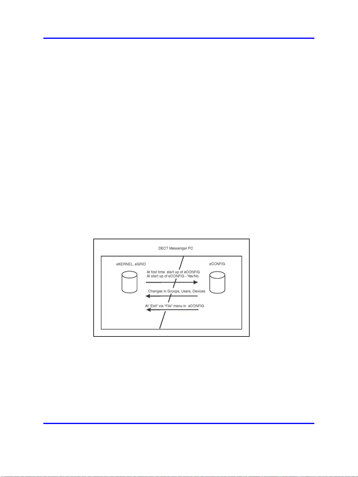
eCONFIG (local) on the DECT Messenger server PC
After the eCONFIG is installed on the DECT Messenger server PC,
the database is handled as shown in “eCONFIG (local) on the DECT
Messenger server PC” (page 14).
Figure 2
Database handling after eCONFIG is on local PC
After you open the eCONFIG for the first time, the eCONFIG makes a
copy of the operational configuration database in DECT Messenger. This
copy is stored in the eCONFIG. If you make configuration changes using
the eCONFIG, these changes are stored in the copy of the database in the
eCONFIG. To make these changes active, you must close down all the
DECT Messenger modules and then close the eCONFIG using the File >
Exit menu. The operational database is deleted automatically, and the
database from the eCONFIG is saved into the DECT Messenger directory
and becomes the new operational database. After you restart the modules
that you closed down, the new configuration becomes active.
Copyright © 2003-2009 Nortel Networks
.
Nortel Communication Server 1000
DECT Messenger Fundamentals
NN43120-120 02.01
11 May 2009
Page 15
Nortel DECT Messenger overview 15
After you make changes in Users, Groups, or Devices, the changes are
saved in the eCONFIG database, as well as in the operational database,
and so are immediately activated.
Note 1:
If you make changes in the database copy that resides in
eCONFIG, ensure that no one else is making changes in the operational
database. If there are other pending changes, an error can occur after
you shut down the eCONFIG and try to write the database into the
DECT Messenger directory.
Note 2:
If there are monitored devices in the active configuration, and
one of these devices initiates a follow-me, the diversion information
is stored in the active database. Therefore, you cannot restore the
eCONFIG database, and all the changes that you make are lost (except
for the changes in Users, Groups, and Devices).
Restarting the eCONFIG After you restart the program, eCONFIG finds
a database in its directory. The eCONFIG asks you whether you want to
continue with this database, or retrieve a fresh copy from the operational
database. Nortel recommends that you make a fresh copy of the
operational database to ensure that there is no database inconsistency.
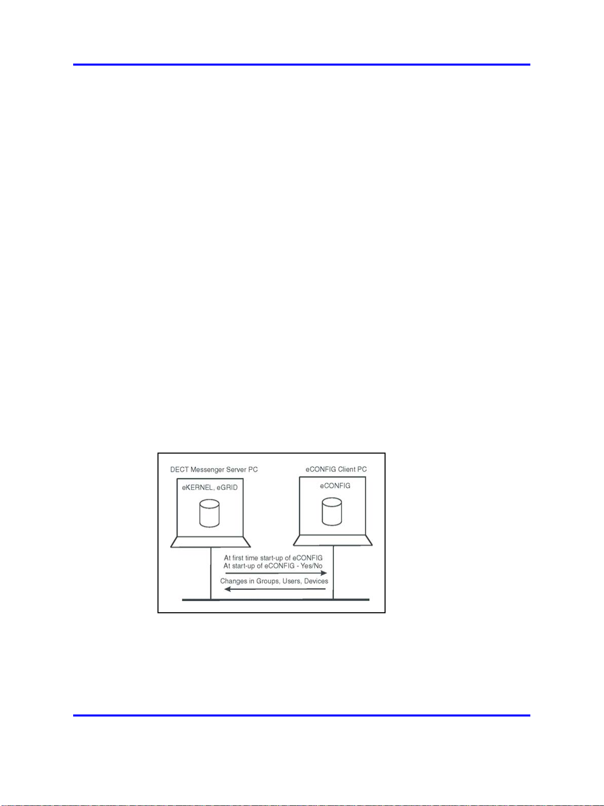
eCONFIG (remote) on remote PC (client) in the network
After the eCONFIG is installed on a remote PC (not the DECT Messenger
server PC) in the network, the database is handled as shown in Figure 3
"Database handling after eCONFIG is installed on a remote PC" (page 15).
Figure 3
Database handling after eCONFIG is installed on a remote PC
After you open the eCONFIG for the first time at the remote PC, a copy
is made of the configuration database of DECT Messenger. This copy
is stored on the remote PC where the eCONFIG is running. You cannot
make system configuration changes in this database, but you can make
changes in Users, Groups, and Devices.
Copyright © 2003-2009 Nortel Networks
.
Nortel Communication Server 1000
DECT Messenger Fundamentals
NN43120-120 02.01
11 May 2009
Page 16
16 Nortel DECT Messenger Administrator Guide
After you make changes in Users, Groups, or Devices, these changes
are stored in the eCONFIG database on your PC. The changes are also
immediately stored in the operational database on the DECT Messenger
(server) PC and are, therefore, immediately active.
Note 1:
If there is more than one eCONFIG active at the same
time, on different PCs, the individual eCONFIG databases are not
updated/synchronized after a user makes a change in one eCONFIG.
Only the database in the eCONFIG module where the change is made
is updated, together with the operational database. Changes made in
Groups using the eWEB interface are not written into the databases
of the eCONFIG modules — these changes are only written into the
operational database.
Note 2:
The database is never saved to the server PC when you work
on a remote PC.
Restarting the eCONFIG After you restart the program, eCONFIG finds
a database in its directory. The eCONFIG asks you whether you want to
continue with this database, or retrieve a fresh copy from the operational
database. Nortel recommends that you make a fresh copy of the
operational database to ensure that there is no database inconsistency.
Database inconsistency can occur after other users make changes in the
database from another PC or at the server PC.
DECT Messenger concepts
DECT Messenger receives alarms (messages) from input modules.
Understanding how these incoming alarms are processed is an important
step towards understanding the eCONFIG menu structure.
Figure 4 "Alarm processing structure" (page 16) shows the relation among
the modules and how messages are processed.
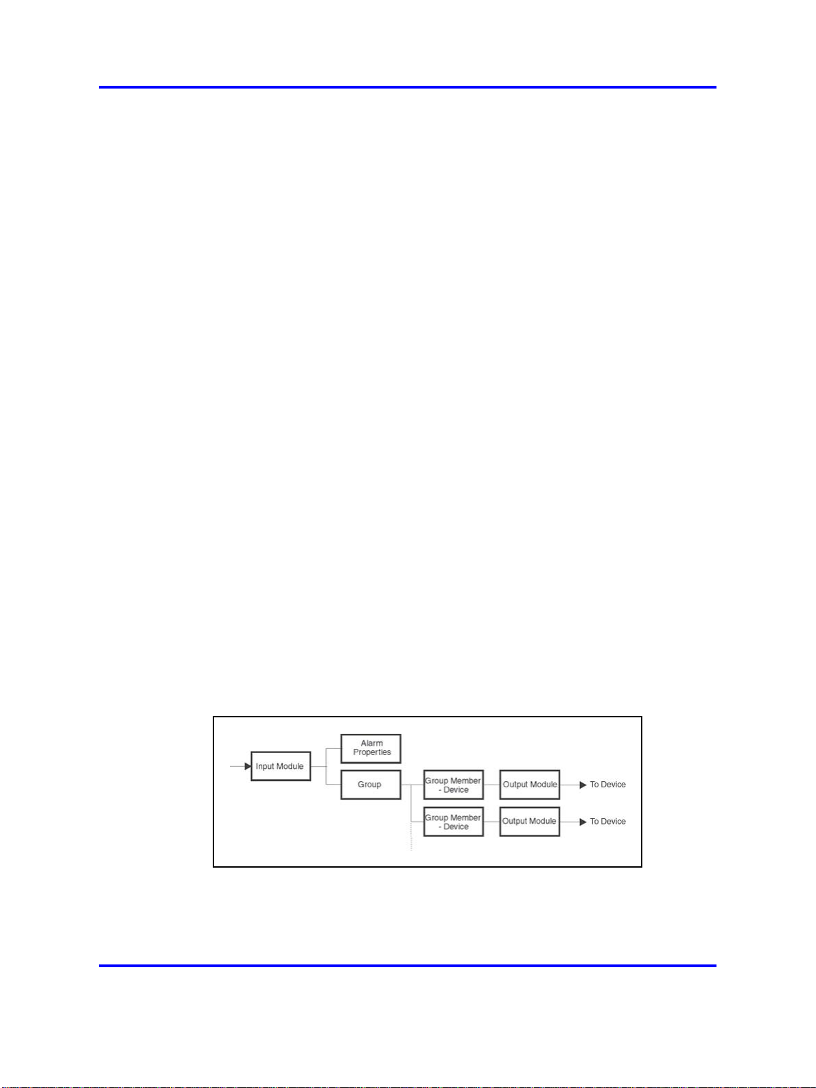
Figure 4
Alarm processing structure
Alarms originate at an input program (input module). An incoming alarm
carries an alarm identifier and a group identifier. The alarm identifier must
match an identifier in the Alarm Properties functional block, which specifies
how the alarm is processed (priority, time intervals, and so on). The group
Copyright © 2003-2009 Nortel Networks
Nortel Communication Server 1000
DECT Messenger Fundamentals
NN43120-120 02.01
11 May 2009
.
Page 17
Nortel DECT Messenger overview 17
identifier determines the final destination. The incoming group identifier
must match a group identifier in the Groups functional block, which
contains one or more output destinations (that is, the group members).
The group members are the devices assigned to a Group.
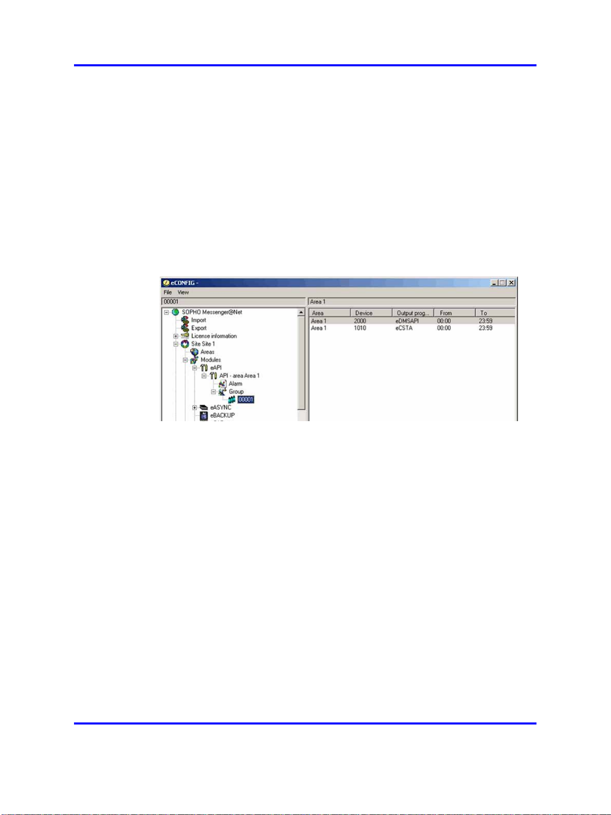
Figure 5 "eCONFIG" (page 17) shows the main window of eCONFIG with
an example of an input module (the application programming interface
[eAPI]). The eAPI input module is found in eCONFIG in the
Modules
> eAPI menu. Select the instance of the module as it appears on your
screen (in this example, the menu selection is Modules > eAPI > API area IBS 1). Each input module displays different properties.
Figure 5
eCONFIG
The following explanations relate to the blocks in “eCONFIG” (page 18):
• Input Module
The Alarm carries two different identifiers from the input module to
the actual Kernel: the alarm identifier and the group identifier. The
identifier provides the message for the output device.
You can set or change the properties of an input module.
• Alarm Properties
The alarm identifier is used to determine how the alarm is processed.
Specifications are in the All Alarms menu (for more information, see
“eCONFIG main window” (page 20)). Examples of the alarm properties
are Priority, Repeat Interval Time, and so on.
Note: There are alarm identifiers predefined in the system
configuration. Therefore, it is not necessary to define all alarm
identifiers.
• Group
Copyright © 2003-2009 Nortel Networks
Nortel Communication Server 1000
DECT Messenger Fundamentals
NN43120-120 02.01
11 May 2009
.
Page 18

18 Nortel DECT Messenger Administrator Guide
The group identifier that originates at the input module determines the
group to which the alarm must be sent. In “eCONFIG” (page 18), the
group identifier is 00001. The group identifier can be a group name
or any string of characters.
• Group Member -- Device
The group is composed of group members, and each group member
is an actual device (for example, an Ergoline, a DECT handset, or an
e-mail address). The output device can be a member of more than one
group. For example, a DECT handset with extension number 2000 can
be assigned to more than one group as a group member. In Figure 5
"eCONFIG" (page 17), Group 00001 has two devices (2000 and 1010).
Device 2000 uses the output program eDMSAPI, which means that
Device 2000 is a DECT handset using E2 messaging.
•
Output Module - Output Program
An output device makes use of an output module, also referred to as
an output program. You can specify settings in the output module to
process the output alarm.
Refer to the following sections for instructions on creating, deleting, and
changing parameters for Groups, Users, and Devices:
eCONFIG
Opening the eCONFIG
• “Managing devices” (page 23)
•
“Managing groups” (page 32)
•
“Managing group members” (page 39)
•
“Managing users” (page 45)
This section contains the following topics related to the eCONFIG:
•
“Opening the eCONFIG” (page 18)
•
“eCONFIG” (page 18)
Procedure 1
Opening the eCONFIG
Step Action
1 Ensure that DECT Messenger is correctly installed and already
preconfigured by a technician.
2 Ensure that the Kernel software is installed and running.
If you are on a remote PC (not the server PC), ensure that the
main server is booted. If you are using the server PC, an icon
Copyright © 2003-2009 Nortel Networks
.
Nortel Communication Server 1000
DECT Messenger Fundamentals
NN43120-120 02.01
11 May 2009
Page 19
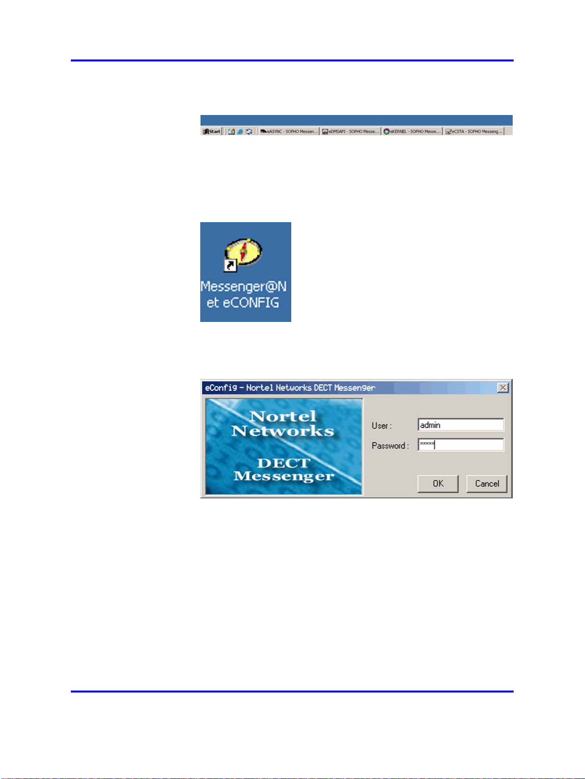
appears in the Windows task bar to indicate that the eKERNEL
is running.
If other modules are also running, an icon is displayed for each
(for example, the eDMSAPI).
3 Start the eCONFIG.
Double-click the eCONFIG icon on the PC desktop.
eCONFIG 19
4 Enter your login information.
The log in dialog box appears:
Log in with the username and password provided by your system
manager. If you are the system manager, and you have not
changed any usernames and passwords yet, log in with the
default login. The default login is admin (username), admin
(password).
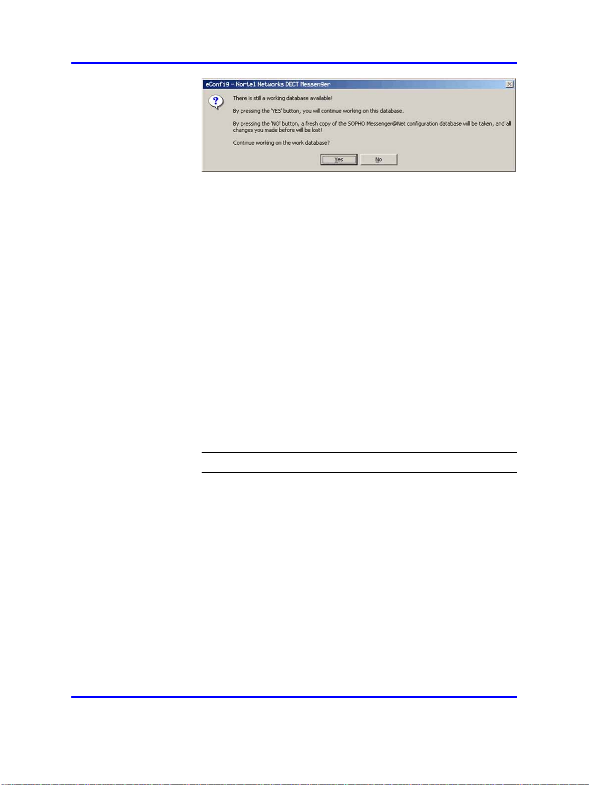
5 Select the database.
The following message box opens:
Copyright © 2003-2009 Nortel Networks
.
Nortel Communication Server 1000
DECT Messenger Fundamentals
NN43120-120 02.01
11 May 2009
Page 20
20 Nortel DECT Messenger Administrator Guide
Note: The eCONFIG asks you which database you want
to use. Ensure that you read the information on database
handling in “eCONFIG basic concepts” (page 14) before
proceeding.
You have two options for database selection:
• Click YES: the eCONFIG uses the database that is still
available in the eCONFIG module from a previous session.
This database can be an old database.
• Click NO: the eCONFIG makes a fresh copy of the
operational database from the DECT Messenger server.
Nortel recommends that you choose this option. It ensures
that you have a copy of the actual operational database. If
you work on a remote PC, you must select this option to
avoid conflicts with changes made from other locations by
other users.
6 The eCONFIG main window opens.
Detailed information is provided in “eCONFIG main window”
(page 20).
eCONFIG main window
The main eCONFIG window is shown in “eCONFIG main window” (page
20).
--End--
Copyright © 2003-2009 Nortel Networks
.
Nortel Communication Server 1000
DECT Messenger Fundamentals
NN43120-120 02.01
11 May 2009
Page 21
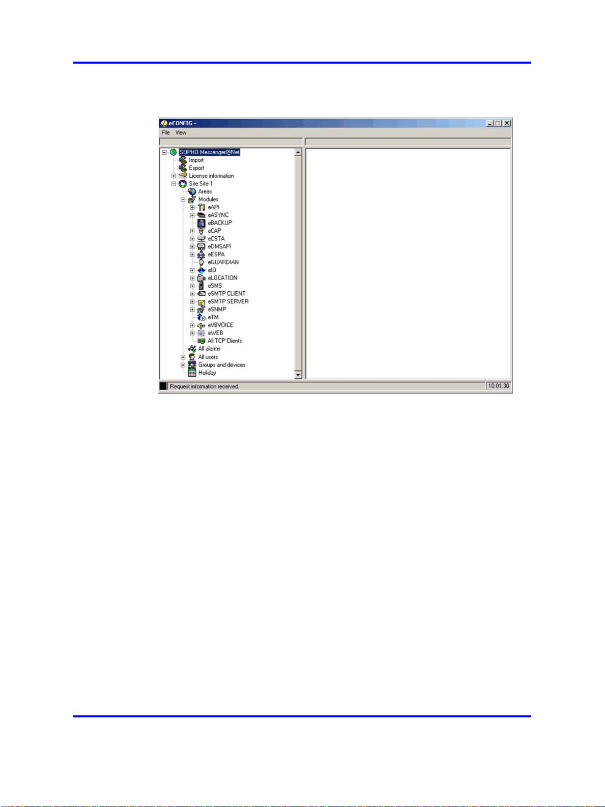
Figure 6
eCONFIG main window
eCONFIG 21
Note: The contents of the eCONFIG window are different for each
user or for each system configuration. “eCONFIG main window” (page
20) shows all the menu items that are possible.
The following menu items are available:
• Import/Export menu: provides the option to import configuration data
into tables in the configuration database, or to export configuration data
from the configuration database tables. The file type is .csv.
Note: Do not use the Import/Export menu items if you do not have
detailed configuration database knowledge. If you make mistakes, it
can corrupt your system.
•
License information: provides information about the current licenses
that are active in your DECT Messenger. You cannot make license
changes from this menu.
• Site Site 1: indicates the location of the eKERNEL (core) software.
There is typically only one eKERNEL in a system, so there is only one
site displayed. (In exceptional cases, there can be more than one site,
but only one eKERNEL (that is, one site) can be active at any given
instant.
Copyright © 2003-2009 Nortel Networks
.
Nortel Communication Server 1000
DECT Messenger Fundamentals
NN43120-120 02.01
11 May 2009
Page 22

22 Nortel DECT Messenger Administrator Guide
• Areas: indicates the subdivisions in a site. Areas are used only if you
have a connection from your DECT Messenger to more than one
DECT Mobility Card (DMC) with DECT. For each connection from your
DECT Messenger to a DMC system or an IP DECT system, you must
specify a different area. Use a number to identify the area. The area
number is used in the various modules in DECT Messenger. Note that
in almost all installations you have only one area.
•
Modules: provides an overview of all the modules in the Messenger.
Note 1:
modules is displayed only if you have view/edit rights.
Note 2:
Clients provides information about the module TCP/IP connections.
You cannot make any configuration changes from this menu.
The list of modules can differ for each user. The list of
All TCP Clients menu item is not a module. All TCP
The
• All Alarms: provides a list of all alarm specifications available in
Messenger.
Note:
Therefore, to create a new alarm specification, you must use the
Module menu. From the All Alarms menu, you can make changes
only to existing alarm specifications.
•
All Users: defines all users. Note that there are two separate groups of
users: eCONFIG users and eWEB users. If you have sufficient rights,
you can change user settings and add new users from this menu.
•
Groups and devices: use this menu to make changes in group and
device characteristics. You cannot create new groups here because a
group is always uniquely linked to an input module. You can, however,
create new devices here because a device does not have a unique
relationship with only one group.
•
Holiday: use this menu to specify the public holidays. This information
is used for the group members. You enable the specified holidays in
the properties for each group member.
The alarm specification is linked to an input module.
Note: If you are using the eCONFIG on a remote PC, you cannot
make changes to property settings. You can change only Users,
Groups, and Devices.
Copyright © 2003-2009 Nortel Networks
.
Nortel Communication Server 1000
DECT Messenger Fundamentals
NN43120-120 02.01
11 May 2009
Page 23

Managing devices
The following sections provide information that explain the following DECT
Messenger tasks:
• creating a new device
• changing the parameters of an existing device
• editing device parameters
The following are examples of device types in DECT Messenger:
• DNR in the DMC
•
Directory Number (DN) in SIP DECT
• e-mail address
• cell phone number (for SMS)
• relay contacts
You must know the properties of each device type relative to the
equipment that hosts it (that is, device properties in the DMC, in the Mail
Server, and so on).
eCONFIG 23
Note: Task procedures are in explained in the following sections. To
carry out these procedures, you must have sufficient user rights to
access all the menus that are used in these procedures. If you do not
have sufficient rights, you cannot see the menu options described, or
you see them but cannot make changes.
Creating a new device
Complete the following steps to create a new device.
Procedure 2
Creating a new device
Step Action
1 Access the eCONFIG Groups and Devices menu.
• Open eCONFIG.
• Expand the Groups and Devices menu by clicking the + to
the left of it.
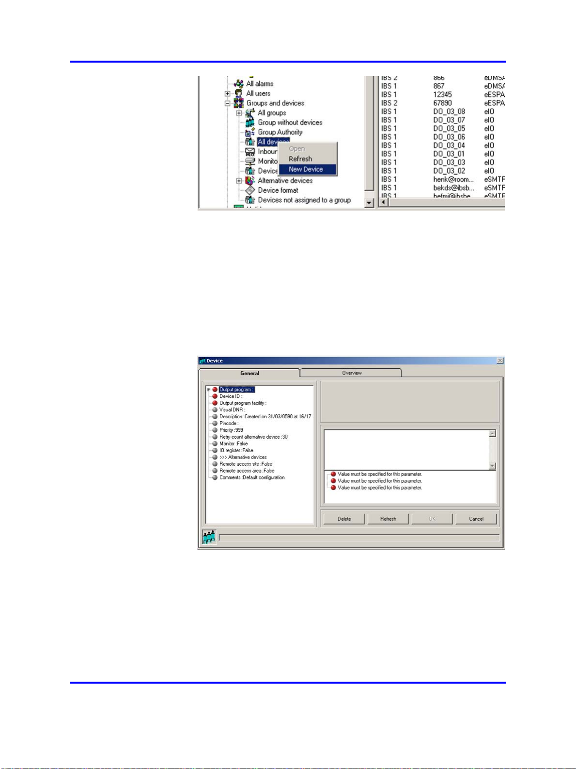
2 Add a new device.
• Right-click the All Devices parameter.
• Select New Device as shown in the following example:
Copyright © 2003-2009 Nortel Networks
.
Nortel Communication Server 1000
DECT Messenger Fundamentals
NN43120-120 02.01
11 May 2009
Page 24
24 Nortel DECT Messenger Administrator Guide
3 Set parameters for the new device.
Note the following when setting parameters:
• A red bullet before an item indicates that the item is
mandatory.
•
Some items contain default parameter values.
• Nortel recommends that you use the Browse option, when
present, to define a location, rather than typing an entry.
The parameters are described in “Device parameters” (page 27).
4 Confirm your choices.
Click OK and follow the instructions on screen.
5 Assign the new device to a group (optional).
Copyright © 2003-2009 Nortel Networks
.
Nortel Communication Server 1000
DECT Messenger Fundamentals
NN43120-120 02.01
11 May 2009
Page 25
Select All Groups from the Groups and Devices menu, or
Group from the input module menu of your choice.
--End--
Changing device parameters
Complete the following steps to change device parameters.
Procedure 3
Changing device parameters
Step Action
1 Access the eCONFIG Groups and Devices menu.
•
Open eCONFIG.
•
Expand the Groups and Devices menu by clicking the + to
the left of it.
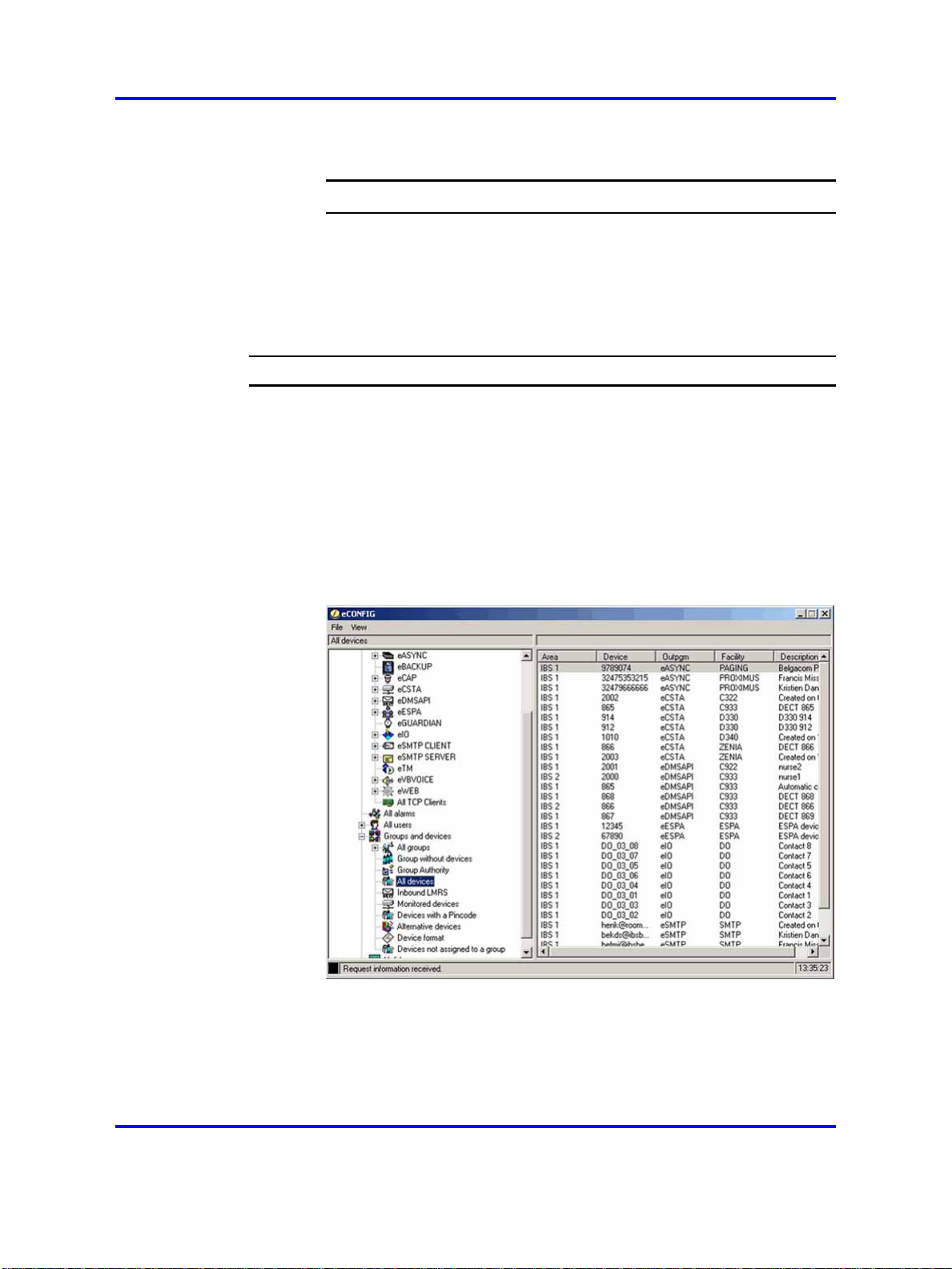
2 Open the All Devices information window.
eCONFIG 25
Left-click the All Devices parameter.
The following window appears:
3 Select the device of your choice.
Copyright © 2003-2009 Nortel Networks
.
Nortel Communication Server 1000
DECT Messenger Fundamentals
NN43120-120 02.01
11 May 2009
Page 26
26 Nortel DECT Messenger Administrator Guide
• In the right panel, browse in the list of devices in DECT
Messenger.
•
Double-click the device that you want to edit. The Properties
window of the device opens:
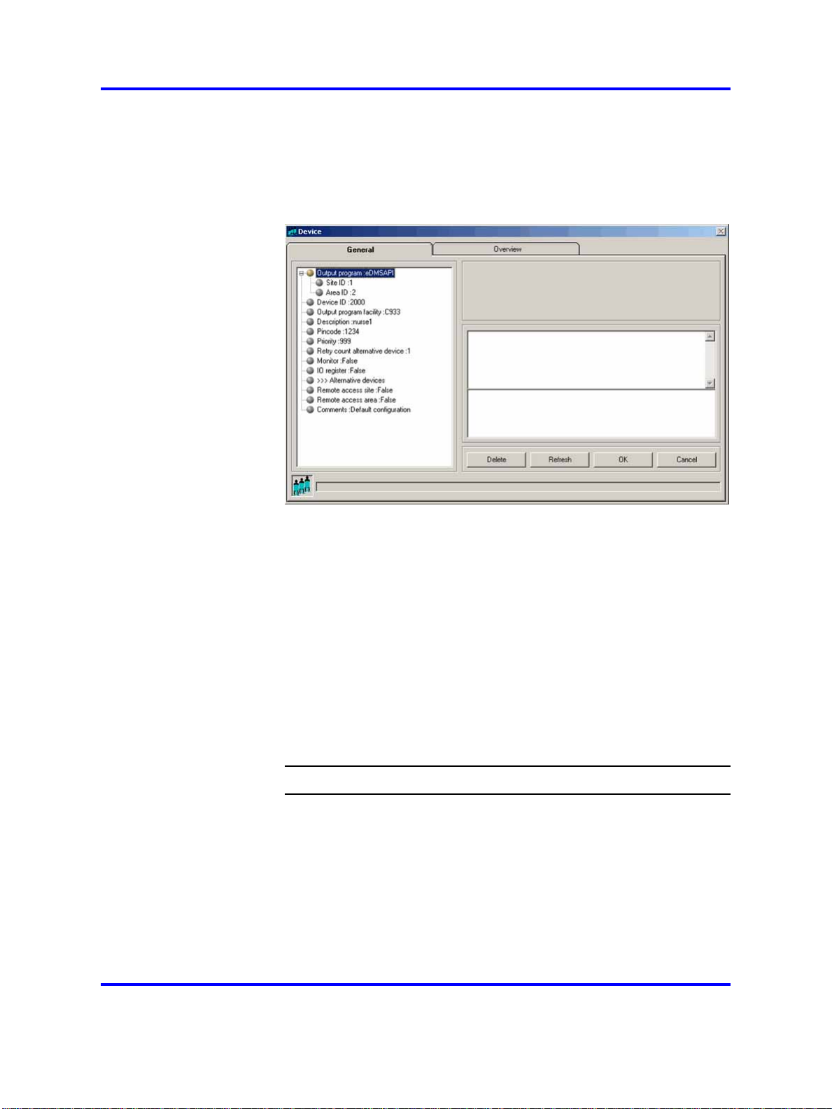
4 Change the parameters.
Click the name of the property you want to change. If you edit
the parameters, note the following:
• You cannot change the Output Program, the Site ID, the
Area ID, or the Device ID.
• Nortel recommends that you use the Browse option, when
present, to define a location, rather than typing an entry.
The parameters are described in “Device parameters” (page 27).
5 Confirm your choices.
Click OK and follow the instructions on the screen, if applicable.
--End--
Deleting a device
To delete a device, follow “Changing device parameters” (page 25);at
Step 4, click the Delete button. DECT Messenger asks you to confirm the
action. After you confirm the action, the device is deleted immediately.
Copyright © 2003-2009 Nortel Networks
.
Nortel Communication Server 1000
DECT Messenger Fundamentals
NN43120-120 02.01
11 May 2009
Page 27

eCONFIG 27
Device parameters
As in previous sections, you can specify the following parameters for a
device:
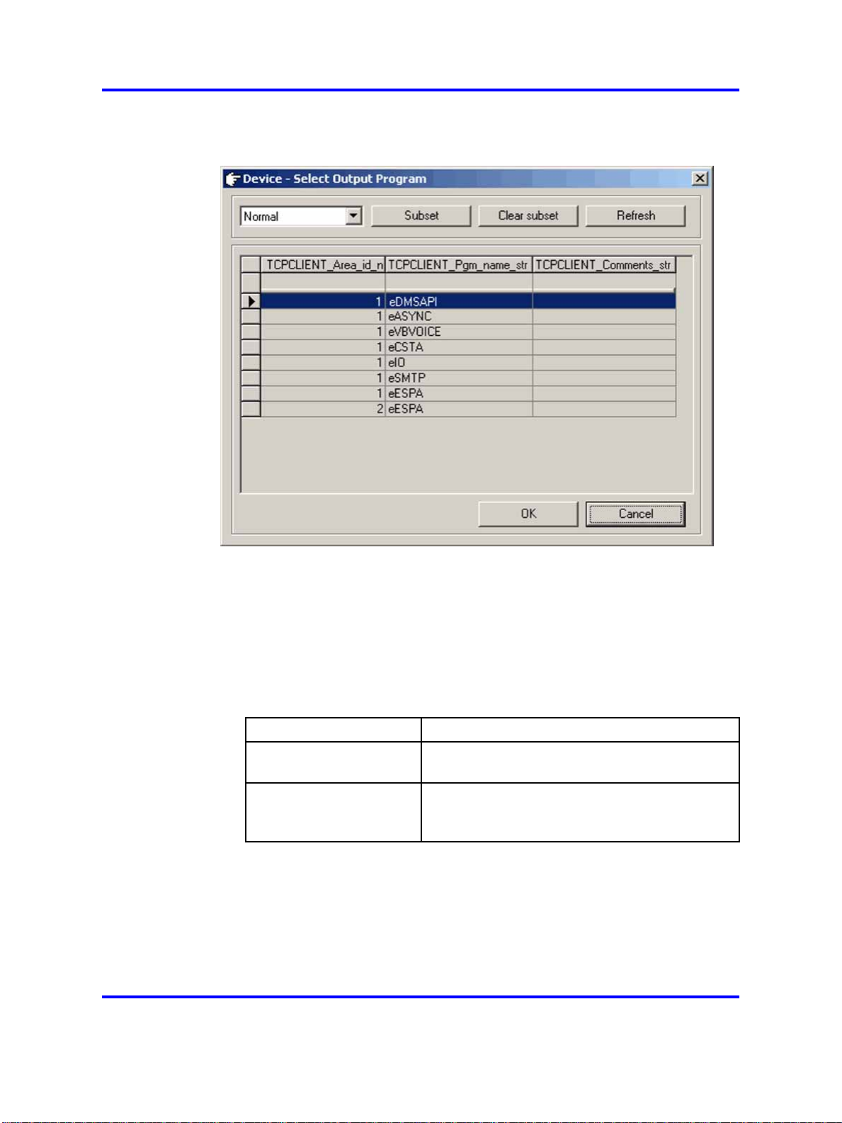
• Output Program
This field specifies the output program that processes a request.
A device can be defined in more than one module. The indicated
application threads the message using the capabilities of the
infrastructure. The eDMSAPI can, for example, send E2 messages
(non-voice-call to extensions such as DECT C4050 and C4060). The
supported output programs are currently:
—
eASYNC for sending SMS to PROXIMUS, or KPN and PAGING to
BELGACOM.
— eDMSAPI for sending E2 messages to DECT handsets that
support E2 (LRMS).
— eESPA for sending messages to an ESPA 4.4.4 interface (pager
equipment).
—
eIO for enabling/disabling discrete output contacts.
— eSMTP for sending e-mail to an e-mail provider.
Note 1:
typically 1) and an Area ID. If there is more than one entry of the
same output program, each one can have a different area. Select
the correct area.
Note 2:
create a new device. Always use the
output program. Figure 7 "Select Output Program browser window"
(page 28) shows the browser window.
The output program is associated with a Site ID (which is
Selecting the output program is only possible when you
Browse button to select the
Copyright © 2003-2009 Nortel Networks
.
Nortel Communication Server 1000
DECT Messenger Fundamentals
NN43120-120 02.01
11 May 2009
Page 28
28 Nortel DECT Messenger Administrator Guide
Figure 7
Select Output Program browser window
• Device ID
The device ID is the actual identifier of the device in the output
equipment.
Device ID consists of <board-id> and <index> delimited with #. For
example, 04#01.
Table 3
Variable definitions
Variable Definition
<board-id> A fixed length value, in the range of 01 to 32,
which indicates the DMC card ID in a PBX.
<index> A variable length value, in the range of 00
to 509, which indicates the index of a DECT
handset subscribed to a DMC card.
The <board-id> value is calculated differently against a system type
as follows:
— For a small system, such as Option 11C, the <board-id> of a
DMC card placed in the Main Cabinet/Chassis is the same as the
card slot number where the DMC card is installed (in the range of
Copyright © 2003-2009 Nortel Networks
.
Nortel Communication Server 1000
DECT Messenger Fundamentals
NN43120-120 02.01
11 May 2009
Page 29
eCONFIG 29
01 to 10). DMC card numbering in Expansion Cabinets/Chassis
continues sequentially in the range 11 to 20.
The following table illustrates Device ID numbering for a small
system.
Table 4
Device ID numbering for a small system
Cabinet/Chassis Card slot <board id> Device ID
Main Cabinet
or Main Chassis
+ Chassis Expander
Expansion Cabinet or
Expansion Chassis 1
+ Expander
1 1 01#xxx
2 2 02#xxx
………
9 9 09#xxx
10 10 10#xxx
1 11 11#xxx
2 12 12#xxx
………
9 19 19#xxx
10 20 20#xxx
— For a large system, such as CS1000E, <board-id> falls in the range
of 01 to 32, and is calculated with the formula:
<board-id> = 16 * <shelf_number> + <card_slot_number> + 1
The following table illustrates Device ID numbering for a large
system.
Table 5
Device ID numbering for a large system
Shelf Card slot <board id> Device ID
0 0 1 01#xxx
The following table shows examples of valid device IDs.
Copyright © 2003-2009 Nortel Networks
.
0 1 2 02#xxx
…… … …
0 14 15 15#xxx
0 15 16 16#xxx
1 0 17 17#xxx
1 1 18 18#xxx
…… … …
1 14 31 31#xxx
1 15 32 32#xxx
Nortel Communication Server 1000
DECT Messenger Fundamentals
NN43120-120 02.01
11 May 2009
Page 30
30 Nortel DECT Messenger Administrator Guide
Table 6
Example device IDs
DMC Card installed in
2nd slot on Main Cabinet on CS1000M, handset is
subscribed with index 01
7th slot of shelf 0 on CS1000E, handset is
subscribed with index 123
14th slot of shelf 1 on CS1000E, handset is
subscribed with index 03
Device ID
02#01
08#123
31#03
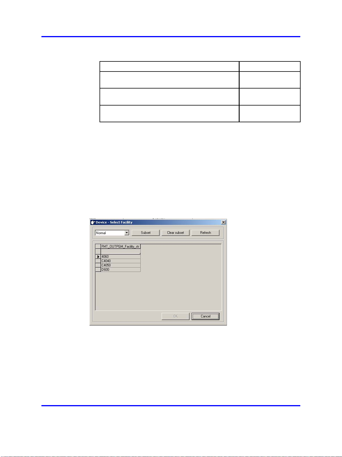
• Output program facility
The indicated application threads the message using the capabilities
of the output device. The display of extensions can differ in character
length, and so on. Therefore, DECT Messenger must know to which
device type the message is being sent (for example, C4050 or 4060
for eDMSAPI).
Use the Browse button to select the correct output program facility.
Figure 8 "Device Select Facility" (page 30) shows the selection window
for the eDMSAPI.
Figure 8
Device Select Facility
• Description
The Description field is used to enter a description of the device. The
description is used to show information about the devices in the web
interface (for example, DECT: John Peterson).
• Pincode
The pincode is used to confirm messages using the eDMSAPI (IC).
Confirmation means that an active alarm on the device is reset from
Copyright © 2003-2009 Nortel Networks
.
Nortel Communication Server 1000
DECT Messenger Fundamentals
NN43120-120 02.01
11 May 2009
Page 31

eCONFIG 31
the same or another extension. To reset the alarm using eDMSAPI
(IC), the CLI of the calling extension must be entered here as the
pincode.
•
Priority
Reserved for future use.
• Retry count alternative device
Retry count alternative device defines how many times the
application tries to deliver the message before switching to an
alternative device (if one is defined in the list of Alternative Devices in
the Groups and Devices menu). The default value is 30. Therefore, if
an alarm has a silence interval (defined in the alarm properties) of 120
seconds, the alarm is removed for this device after one hour (and set
for the alternative device, if defined).
A value of 0 indicates that the application never tries to send the
message to an alternative device, and that the alarm is sent to the
device every silence interval until the alarm is reset by the input
program, for example (a reset). A value of 1 indicates that after one
attempt, the application clears the message for this device and send
the message to the alternative device, if defined.
Note: In this second case (value=1), the switch to the alternative
device is immediate (that is, there is no silence interval between
the two calls). Therefore, you must ensure that there are no loop
conditions defined in the list of alternative devices.
A value of 2 indicates that the alternative device is contacted after the
second attempt.
•
IO Register
This parameter is only applicable for devices that are assigned to
output program eDMSAPI.
All devices with this value set to True are monitored by the eDMSAPI
to see if an E2 message is sent. After a device sends an E2 message,
the message always goes to DECT Messenger directly (and not to
the destination number). Messages sent to DECT Messenger are
processed by DECT Messenger in the same way that messages
from other input devices are processed. There must be a correct
specification in the eDMSAPI inbound configuration that points to a
group and an alarm. The message is sent to the group members in the
group that is assigned to the inbound configuration in the eDMSAPI.
• Alternative devices
Use this parameter to assign one or more alternative devices to a
device. After you click this item, a panel at the right side of the window
displays the list of possible alternative devices. Select New from the
menu to add an alternative device. Select Edit to make changes in the
list of alternative devices already assigned to this device.
Copyright © 2003-2009 Nortel Networks
.
Nortel Communication Server 1000
DECT Messenger Fundamentals
NN43120-120 02.01
11 May 2009
Page 32

32 Nortel DECT Messenger Administrator Guide
• Remote access site
The Remote access site parameter is only applicable when you
have more than one site, and you are using the web interface. A web
server (eWEB) and a device are each assigned to only one site; if
both are assigned to the same site, you can see the device from the
web interface. Devices assigned to sites other than that to which the
web server is assigned are only visible if the Remote access site
parameter is set to True.
• Remote access area
The Remote access area parameter is only applicable when you
have more than one area, and you are using the web interface. A web
server (eWEB) and a device are each assigned to only one area; if
both are assigned to the same area, you can see the device from the
web interface. Devices assigned to areas other than that to which the
web server is assigned are only visible if the Remote access area
parameter is set to True.
•
Comments
This field is informational only, and can contain remarks from the
administrator.
Managing groups
Creating a new group
Complete the following steps to create a new group.
Procedure 4
Creating a new group
Step Action
1 Open eCONFIG.
2 Access the pop-up menu of the input module for which you want
to create the new group.
• Select the input module for which you want to create a new
group from the Modules menu.
Note: A group is always associated with an input module. You
cannot create a new group in the Groups and Devices menu.
Copyright © 2003-2009 Nortel Networks
.
Nortel Communication Server 1000
DECT Messenger Fundamentals
NN43120-120 02.01
11 May 2009
Page 33

eCONFIG 33
• Expand the input module for which you want to create a new
group. The instances (eAPI - area Area 1 in this example) of
the input module are displayed.
•
Expand the instance.
The submenu items Alarm and Group are displayed.
• Expand Group to view all the groups for this instance of the
input module.
•
Right-click the Group parameter.
A pop-up menu opens.
3 Create the new group and set the parameters.
• Select New Group from the Group pop-up menu.
• Enter values for the group parameters.
After you enter the parameters, note the following:
Copyright © 2003-2009 Nortel Networks
.
Nortel Communication Server 1000
DECT Messenger Fundamentals
NN43120-120 02.01
11 May 2009
Page 34

34 Nortel DECT Messenger Administrator Guide
• A red bullet before an item indicates that the parameter is
mandatory.
•
Some items contain default parameter values.
• Nortel recommends that you use the Browse option, when
present, to define a location, rather than typing an entry.
Note 1: The group name that you enter must match the group
name entered for the input module. If the input module is
an eAPI, eCAP, or eESPA, the group name matches that in
the external system. Therefore, you must know the external
system that delivers the group name.
Note 2: The input module provides not only a group name,
but also an alarm. Ensure that the alarm from the input
module corresponds to an alarm in the alarms list. Ask a
system specialist if you are uncertain about this.
The parameters are described in more detail in “Group
parameters” (page 36).
4 Confirm your choices.
Click OK and follow the instructions on the screen, if applicable.
--End--
Changing group parameters
Complete the following steps to change group parameters.
Procedure 5
Changing group parameters
Step Action
1 Open eCONFIG.
2 Select the input module for which you want to change the group
parameters.
Select the input module for which you want to change group
parameters from the Modules menu.
Note: A group is always associated with an input module.
However, to change group parameters, you can also select a
group from the Groups and Devices menu.
3 Open the group.
Copyright © 2003-2009 Nortel Networks
.
Nortel Communication Server 1000
DECT Messenger Fundamentals
NN43120-120 02.01
11 May 2009
Page 35

eCONFIG 35
• Expand the input module for which you want to create a new
group. The instances (eAPI - area IBS 1 in this example) of
the input module are displayed.
• Expand the instance.
The submenu items
•
Expand the Group item to view all the groups for this
instance of the input module.
•
Right-click the Group parameter.
A pop-up menu opens.
Note: This illustration shows the eAPI input module.
Alarm and Group are displayed.
• Select Open.
4 Change group parameters.
The parameters are described in section “Group parameters”
(page 36).
Copyright © 2003-2009 Nortel Networks
The Group Properties/Parameters window opens.
Nortel Communication Server 1000
DECT Messenger Fundamentals
NN43120-120 02.01
11 May 2009
.
Page 36

36 Nortel DECT Messenger Administrator Guide
5 Confirm your choices.
Click OK and follow the instructions on the screen, if applicable.
--End--
Deleting a group
To delete a group, follow “Changing group parameters” (page 34); at Step
4, click the Delete button. DECT Messenger asks you to confirm the
action. After you confirm the action, the group is deleted immediately.
Group parameters
You can specify the following group parameters for a device:
• Group ID
The Group ID field defines a unique identifier for a group. The field is
a unique key in the database that is created automatically after you
create a new group. The ID consists of an input program identifier and
the group name that you (initially) assigned to the group. This group ID
has an internal (that is, in the database) link to the group members.
• Group name
The Group name field shows the group indicator that is typically
received from the external alarm system through the input program (or
generated by the input program itself if the external alarm system does
not provide a group name). In many environments, alarm systems are
capable of sending destination information in the alarm string. For
instance, destination information can be referred to with terms such as
Copyright © 2003-2009 Nortel Networks
.
Nortel Communication Server 1000
DECT Messenger Fundamentals
NN43120-120 02.01
11 May 2009
Page 37

eCONFIG 37
paging number, group, or destination. In most cases, the group names
are determined by third-party vendors and cannot be changed.
Note:
input program. You can use the same group name because the
DECT Messenger software adds the input program ID to the group
name, which makes the group ID unique. This group ID is created
automatically after you create the group. However, you can change
the group name later. The Group ID remains the same.
•
Description
Administrators can easily recognize the group (for example, Intensive
Care) by reading the descriptive text in the Description field.
•
Comments
The Comments field contains additional information. For example,
"Warning: minimum three DECT extensions required".
•
Input program
The Input program parameter provides information about the input
program. You cannot change this parameter. After you create a
new group for an input program, these parameters are assigned
automatically.
•
Group members
Use the Group members parameter to assign group members to
the group (assign devices to the group from the list of devices). After
assigned, these devices become group members. If the device (for
example, an extension) that you want to assign is not in the list, create
that device first according to the procedures “Creating a new device”
(page 23).
You can use the same group name for more than one
Use the Group members menu to open the window shown in Figure 9
"Group members window" (page 38).
Copyright © 2003-2009 Nortel Networks
Nortel Communication Server 1000
DECT Messenger Fundamentals
NN43120-120 02.01
11 May 2009
.
Page 38

38 Nortel DECT Messenger Administrator Guide
Figure 9
Group members window
The section “Changing group member parameters” (page 42) provides
information on assigning new members, editing members, and deleting
members.
• Group authority
The Group authority field defines which users are granted access to
the group to make changes using the eWEB interface, or to use the
eCONFIG. If you specify ALL, all users have access to this particular
group, and you do not need to enter all individual users. As a result,
however, you have no granular authority definition, because all users
are granted access. Note that eWEB allows only maintenance of
the groups that are assigned to input programs of the same site as
the eWEB. For example, an eWEB instance of site 1 allows only
maintenance of groups of site 1.
Use the Group authority menu to open the window shown in Figure
10 "Group authority" (page 39).
Copyright © 2003-2009 Nortel Networks
.
Nortel Communication Server 1000
DECT Messenger Fundamentals
NN43120-120 02.01
11 May 2009
Page 39

Figure 10
Group authority
eCONFIG 39
Click the New button to give a new user the authority to make changes
in the group. Click the Edit button to edit a user authority.
WARNING
If you want to delete a user from this group, do not click
Delete in the window shown in Figure 10 "Group authority"
(page 39), because that deletes the entire group. Instead,
click Edit. A window specifically for that user opens. Click
Delete in this window to remove the user from the group.
Managing group members
A group has group members. These are devices to which an alarm for
that group is sent. You can assign new members to a group, and you can
delete members from a group. These procedures are described in the
following sections:
•
“Assigning a new member to a group” (page 39)
•
“Changing group member parameters” (page 42)
• “Removing a group member” (page 43)
•
“Member parameters” (page 44)
Assigning a new member to a group
Complete the following steps to assign a new member to a group.
Copyright © 2003-2009 Nortel Networks
.
Nortel Communication Server 1000
DECT Messenger Fundamentals
NN43120-120 02.01
11 May 2009
Page 40

40 Nortel DECT Messenger Administrator Guide
Procedure 6
Assigning a new member to a group
Step Action
1 Open eCONFIG.
Ensure that the member that you want to assign to the group is
already in DECT Messenger as a device. (A group member is a
device that is assigned to a group.) If the member does not exist
as a device, see “Creating a new device” (page 23).
2 Access the Group Properties window.
Use one of the following methods to access the Group
Properties window:
•
Select Input Module from the Modules menu.
•
Expand the input module for which you want to create a new
group.
• Expand the module instance. The submenu items Alarm and
Group display.
•
Expand the Group item.
• Right-click the Group parameter. A pop-up menu displays.
•
Select Open. The Group Properties/Parameters window
opens.
or
• Expand the Groups and Devices menu in the eCONFIG
main window.
• Expand the All groups menu. All the groups are displayed.
•
Open the group properties window by either double-clicking
the group that you want to edit, or right-clicking on the group
and selecting Open.
Copyright © 2003-2009 Nortel Networks
.
Nortel Communication Server 1000
DECT Messenger Fundamentals
NN43120-120 02.01
11 May 2009
Page 41

3 Open the Group members window.
Click the >>>Group members item.
eCONFIG 41
A list of group members displays (the example shows only one
group member: device 1010).
4 Add a new member.
•
Copyright © 2003-2009 Nortel Networks
.
Click New. The following window opens.
Nortel Communication Server 1000
DECT Messenger Fundamentals
NN43120-120 02.01
11 May 2009
Page 42

42 Nortel DECT Messenger Administrator Guide
• Click the Device ID menu item.
• Use the Browse button to select the device that you want to
add as a member to the group.
Note: After you select a device, the area and output program
are defined automatically for the member.
For more information on the parameters, see “Member
parameters” (page 44).
5 Confirm your choices.
Click OK and follow the instructions on the screen, if applicable.
--End--
Changing group member parameters
Complete the following steps to change the parameters for a group
member.
Procedure 7
Changing group member parameters
Step Action
1 Open the Group members window.
Follow Steps 1, 2, and 3 in “Assigning a new member to a group”
(page 39).
2 Select the group member to edit.
Copyright © 2003-2009 Nortel Networks
.
Nortel Communication Server 1000
DECT Messenger Fundamentals
NN43120-120 02.01
11 May 2009
Page 43

eCONFIG 43
In the right panel of the window is a list of one or more group
members that are assigned to the group. Select the group
member that you want to edit, and click
Edit.
3 Change the parameters.
A window, similar to the one in Step 4 of “Assigning a new
member to a group” (page 39), opens, however all parameters
are entered.
•
Click the item you want to change.
Note: You can change all parameters except the group ID
and the parameters for device ID.
4 Confirm your choices.
Click OK and follow the instructions on the screen, if applicable.
--End--
Removing a group member
Complete the following steps to remove a member from a group.
Procedure 8
Removing a group member
Step Action
1 Open the Group members window.
Follow Steps 1, 2, and 3 in “Assigning a new member to a group”
(page 39).
2 Select the group member to remove.
In the right panel of the window is a list of one or more group
members that are assigned to the group. Select the group
member that you want to edit, and click Edit.
3 Remove the member from the group.
A window, similar to the one in Step 4 of “Assigning a new
member to a group” (page 39), opens, however all parameters
are entered.
• Remove the member by clicking the Delete button.
4 Confirm your choices.
Click OK and follow the instructions on the screen, if applicable.
Copyright © 2003-2009 Nortel Networks
.
--End--
Nortel Communication Server 1000
DECT Messenger Fundamentals
NN43120-120 02.01
11 May 2009
Page 44

44 Nortel DECT Messenger Administrator Guide
Member parameters
Member parameters are parameters that are added to a device for a
specific group. These parameters are only applicable for the combination
of a device and a group, and can be different after the same device is
assigned to another group.
The following parameters can be specified for a group member:
•
Group ID
The Group ID field defines a unique identifier for a group. The field
is a unique key in the database that is created automatically after
you create a new group. You cannot change the Group ID at this
parameter.
• Device ID
Use the Device ID parameter to assign each device as a member of a
group. Always use the Browse button that is active after you click this
menu item.
The parameters display after you select each device, because these
are linked to the device that you select.
•
From:
The From: value contains a value in format xx:xx, where a valid hour
and time must be specified. Valid range is 00:00 to 23:59. Incorrect
values give unpredictable results. The value denotes the start of the
time interval during which the defined device is active as a member
of the group. For example, a value of 00:00 indicates that the group
member is active at midnight. Value 12:00 specifies that the group
member starts at noon. The time interval ends in the time specified in
the To: value.
•
To:
The To: value contains a value in format xx:xx, where a valid hour
and time must be specified. Valid range is 00:00 to 23:59. Incorrect
values give unpredictable results. The value denotes the end of the
time interval during which the defined device is active as a member
of the group. For example, a value of 23:59 indicates that the group
member becomes inactive at midnight. A value of 12:00 specifies that
the group member stops its activity at noon. The time interval begins
at the time specified in the From: value (see the previous bullet). The
From: value can be larger than the To: value. In this case, the active
time can start at 21:00 and end at 06:00 (night-shift). Also note that a
member can be active from both 08:00–12:00 and 13:15–17:30. To
define two time intervals for the same device, you must define it as two
group members (same device): one active from 08:00–12:00, and the
other active from 13:15–17:30.
• Monday . . . . Saturday
Copyright © 2003-2009 Nortel Networks
.
Nortel Communication Server 1000
DECT Messenger Fundamentals
NN43120-120 02.01
11 May 2009
Page 45

eCONFIG 45
This value is a Boolean value: True or False. After set to True, the
member is active on that day.
•
Holiday
This value is a Boolean value: True or False. After set to True, the
member is to be present on holidays. The holidays are defined in the
Holiday parameter of the eCONFIG menu.
• Activate Timestamp
The Activate Timestamp value specifies the time after the
member record is activated. The timestamp is formatted as follows:
YYYYMMDDHHMMSS (for example: 20010101000000). The Activate
Timestamp and Deactivate Timestamp is used to define a time
interval during which records are active. This functionality is typically
used in environments where there is extensive up-front planning of
staff resources, flexible schedules, holiday periods, and so on.
• Deactivate Timestamp
The Deactivate Timestamp value specifies the time after the
member record is deactivated. The timestamp is formatted as follows:
YYYYMMDDHHMMSS (for example: 20010101000000). The Activate
Timestamp and Deactivate Timestamp is used to define a time
interval during which records are active. You can use this functionality
to anticipate future changes in availability of staff, and is typically used
in environments where there is extensive up-front planning of staff
resources, flexible schedules, holiday periods, and so on.
•
Comments
The Comments field contains additional information for administrative
purposes.
Note: If a group member is not active because of the member
settings, overflow to alternative devices is not activated.
Managing users
DECT Messenger makes a distinction between the users for eWEB and
users for eCONFIG. The mechanisms for handling these users are exactly
the same. The only difference is that the eWEB users are applicable for
Login and Authority levels in eWEB, and eCONFIG users are applicable
for Login and Authority levels in eCONFIG.
Creating a new user
The following procedure describes how to create a new user.
Copyright © 2003-2009 Nortel Networks
.
Nortel Communication Server 1000
DECT Messenger Fundamentals
NN43120-120 02.01
11 May 2009
Page 46

46 Nortel DECT Messenger Administrator Guide
Procedure 9
Create a new user
Step Action
1 Open eCONFIG.
2 Expand the All Users menu.
Note: Two submenu items are listed: eWEB and eCONFIG.
eWEB contains the users for eWEB, while eCONFIG contains
the users for eCONFIG. These are separate from each other,
however the approach and authority mechanism is the same,
so the steps in this section apply to both.
3 Access the pop-up menu.
In the All users menu, right-click either eCONFIG or eWEB.
4 Create a new user.
Depending on the option you chose in step 3, select one of the
following:
• New eConfig User
• New eWEB User
5 Enter the parameters for the new user.
Select each item in the left panel and enter parameters.
Copyright © 2003-2009 Nortel Networks
.
Nortel Communication Server 1000
DECT Messenger Fundamentals
NN43120-120 02.01
11 May 2009
Page 47

The parameters are explained in “User parameters” (page 49).
6 Confirm your choices.
Click OK and follow the instructions on the screen, if applicable.
eCONFIG 47
--End--
Changing user properties
The following procedure describes how to change the properties for user.
Procedure 10
Changing user properties
Step Action
1 Open the Group Members window.
2 Expand the All Users menu.
Two menu items are available: eWEB and eCONFIG. eWEB
contains the users for eWEB and eCONFIG contains the users
for eCONFIG. These are separate from each other, however the
approach and authority mechanism is the same, so the steps in
this section apply to both.
3 Select the menu item that contains the user you want to edit.
Select either eCONFIG or eWEB, depending on where the user
resides. A list of users opens in the right panel.
4 Open the Properties window for the user you want to edit.
Double-click the user for which you want to change the
properties.
Copyright © 2003-2009 Nortel Networks
.
Nortel Communication Server 1000
DECT Messenger Fundamentals
NN43120-120 02.01
11 May 2009
Page 48

48 Nortel DECT Messenger Administrator Guide
5 Change the parameters.
Change the parameters by clicking the item and changing the
field contents.
The parameters are explained in “User parameters” (page 49).
6 Confirm your choices.
Click OK and follow the instructions on the screen, if applicable.
--End--
Deleting a user
The following procedure describes how to delete a user.
Procedure 11
Deleting a user
Step Action
1 Open the User Properties window.
Follow Steps 1, 2, 3, and 4 of the procedure in “Changing user
properties” (page 47).
2 Delete the user.
Click the Delete button.
3 Confirm your choices.
Click OK and follow the instructions on the screen, if applicable.
Copyright © 2003-2009 Nortel Networks
.
--End--
Nortel Communication Server 1000
DECT Messenger Fundamentals
NN43120-120 02.01
11 May 2009
Page 49

eCONFIG 49
User parameters
The following parameter descriptions are applicable for the parameters for
both eWEB and eCONFIG users.
• User ID
This is the username that must be entered in the login dialog box.
Maximum length is ten characters. Nortel recommends that you create
a user profile for each user who has access to the eWEB interface.
Sharing user profiles can result in unauthenticated users, which
generates alarms.
• Password
This field contains a password with a maximum length of ten
characters. Users can change their own password using the eWEB
interface. You can create new users with default passwords (for
example, the same as the user identifier), and request that the users
change their password at first usage.
Note: Passwords are stored without encryption in the DECT
Messenger structure. Therefore, hackers can retrieve authentication
information from the system. Also, table information can be
made available through eWEB (depending on your configuration).
Because the security mechanism is limited, Nortel recommends that
you not use any passwords that are used on other systems that
contain secured information. Using identical passwords across both
secured and less-secured environments leads to severe security
exposure. Inform all users of this issue.
•
Security level
You can use the security level parameter to define a number in the
range of 00–99. The higher the number, the more authority a user is
given. The value 99 is the highest level which gives full access to all
menu items, and allows read and edit. This value can be assigned to
top-level administrators. The value 00 is the lowest possible value.
Nortel recommends that you limit the number of initially assigned
values to 2 or 3 levels, and handle increments by 10. Good start
values are 20 for low-end users, 40 for mid-range users, and 60 for
administrators. As you become familiar with user patterns, a more
granular level of security can be defined for users.
Note 1: The level is related to the values specified in the table of
contents of the eWEB module where a read and edit threshold level
is assigned to each individual menu. For example, a user with level
20 can execute all the functions with level 00 up to 20.
Note 2:
fixed. For all menus, the read level threshold is 10, and the edit
level threshold is 30.
• Description
Copyright © 2003-2009 Nortel Networks
In the eCONFIG, the level thresholds for the menus are
Nortel Communication Server 1000
DECT Messenger Fundamentals
NN43120-120 02.01
11 May 2009
.
Page 50

50 Nortel DECT Messenger Administrator Guide
This is a text description of the user, and is for administrative purposes
only. The real name of the user is often stored in this field.
• Language
You must enter a four-digit code representing the language for the
eWEB module. For the eCONFIG you must fill in a two-character
representation for the language (for example, EN represents English).
If you make a mistake, only menu icons are displayed, and not the
menu items.
—
Language field for eWEB user
The language field contains a four-digit identifier that represents the
language used for eWEB and eGRID access. The codes are those
used in an iSeries 400, and are in the range of 29xx. Currently
supported values in eWEB are the following:
– 2909: Belgian English
– 2963: Belgium Dutch
–
2966: Belgium French
Check the commercial documentation to determine if other
languages are available. If other languages are available, the
codes are as follows:
– 2922: Portuguese
–
2923: Dutch Netherlands
–
2924: English
–
2925: Finnish
–
2926: Danish
– 2928: French
–
2929: German
–
2931: Spanish
–
2932: Italian
–
2933: Norwegian
– 2937: Swedish
– 2980: Brazilian Portuguese
— Language field for eCONFIG user
The language identifier for the eCONFIG consists of a
two-character identifier. For example, EN represents English,
NL represents Dutch, and so on. Check with the commercial
department to determine which languages are available.
• e-mail address
Copyright © 2003-2009 Nortel Networks
.
Nortel Communication Server 1000
DECT Messenger Fundamentals
NN43120-120 02.01
11 May 2009
Page 51

Adding a DECT device to the Messenger system 51
The e-mail address field contains the e-mail address of the user.
After the user sends an e-mail using the web interface (Send SMTP
Message menu), this e-mail address is used in the From: field (that
is, the originator address).
•
All object authority
The user can maintain all groups in DECT Messenger with the All
object authority parameter. Remember that a user can be assigned
to a group. After assigned to a group, the user (when logged in) can
make changes in the group configuration of the groups to which this
user is assigned. However, if the All object authority option is set to
True, the user is allowed to maintain and make changes in all groups
in DECT Messenger. This gives the user administrator privileges for
all groups.
In most cases, the False value is used so that the user does not have
all object authority.
•
Security administrator
The Security administrator value is set to either True or False. Set
the option to True to allow the user to maintain the user settings of
other users (that is, to give the user Administrator rights for all other
users, including the right to change passwords, and so on).
There is a difference in implementation between the eWEB and the
eCONFIG:
— Security administrator rights in eWEB
After a user with security administrator rights logs in to the web
interface, that user has access to view the eWEB_USER_AUTH table
in which the user passwords are visible in ASCII text. The user can
also change the passwords for all users using the Change Password
option.
—
Security administrator rights in eCONFIG
Users with security administrator rights in the eCONFIG see a list of
all users in the All users > eConfig user menu. These users can
change settings and passwords for all users, delete users, and create
new users.
Users with no security administrator rights see only their name in the
All users > eConfig user menu, and can change only their password
(and no other settings).
• Comments
The Comments field contains additional information for administrative
purposes.
Adding a DECT device to the Messenger system
Use the following steps to add the basic configuration for a DECT handset.
Nortel Communication Server 1000
DECT Messenger Fundamentals
NN43120-120 02.01
Copyright © 2003-2009 Nortel Networks
.
11 May 2009
Page 52

52 Nortel DECT Messenger Administrator Guide
Procedure 12
Adding a DECT device to the Messenger system
Step Action
1 Configure a device format.
Ensure that you have a Device Format for this type of DECT
handset. For information about configuring device formats,
refer to
DECT Messenger Installation and Commissioning
(NN43120-301).
Browse to Groups and Devices > Device Format. If your
DECT Handset is configured under Device Format on the
eConfig module, your DECT handset type is shown beside the
eDMSAPI output program.
2 Add new Device.
Within Groups and Devices, right click All Devices, and choose
New Device.
3 Configure the new device.
Make the following configuration changes:
• Select eDMSAPI as the Output program.
• For Device ID, enter either:
Copyright © 2003-2009 Nortel Networks
.
Board_Number#Index_Number if you are configuring
traditional DECT handsets
OR
a DN if you are configuring SIP DECT handsets.
Example: For a DMC Card in Slot 4 of an Option 11c
Cabinet, and a DECT handset subscribed to index 2, the
Device ID is 04#02.
Nortel Communication Server 1000
DECT Messenger Fundamentals
NN43120-120 02.01
11 May 2009
Page 53

For more information about Device ID, see “Device
parameters” (page 27)
• Configure the Output Program Facility according to the type
of DECT handset you have.
Example: C4050
•
Visual DNR
The Directory Number (DN) of the DECT handset.
Example: 2947
•
Description
Add a description of the handset. This can be the name of
the handset owner.
Example: Emmett Lee
This description is displayed on the eWeb ’Send DMS-API
Message’ Extension box.
• Set IO Register to True
4 Check alarms.
• In eCONFIG, open the menu Modules, and expand the
eDMSAPI module by clicking the + beside it. Under the
eDMSAPI module, the instances of the input module (For
example, eDMSAPI - area One) are listed. Expand this
instance. The items Alarm and Group appear. Click Alarm.
Adding a DECT device to the Messenger system 53
• Ensure that you have at least two Alarms, as follows:
— E2_MSG_N
— E2_MSG_U
5 Add a group.
• In eCONFIG, open the menu Modules, and expand the
eDMSAPI module by clicking the + beside it. Under the
eDMSAPI module, the instances of the input module (For
example, eDMSAPI - area One) are listed.
• Expand this instance. The items Alarm and Group appear.
• Right-click Group, and select New Group in the pop-up
menu.
6 Configure the new group.
Make the following configuration changes:
• Populate the Group_Name. If you are adding a single DECT
handset, use the DN of this handset as the group name.
• Populate the Description
Copyright © 2003-2009 Nortel Networks
.
Nortel Communication Server 1000
DECT Messenger Fundamentals
NN43120-120 02.01
11 May 2009
Page 54

54 Nortel DECT Messenger Administrator Guide
• Group Members. Click New. Browse under Device_ID for the
device you created in Step 2.
•
Group Authority. Click New. Under User_ID browse for *ALL
7 Open the Inbound data call handling menu.
• In eConfig, open the menu Modules, and expand the
eDMSAPI module by clicking the + beside it. Under the
eDMSAPI module, the instances of the input module (For
example, eDMSAPI - area One) are listed.
• Right-click the instance of the eDMSAPI module (For
example, eDMSAPI - area One), and click Open in the
pop-up menu.
•
Scroll to the bottom of the menu and expand Inbound
data-call handling.
• 3 choices are displayed:
— Inbound
— Inbound Event
— Inbound Result
8 Configure Inbound data call handling.
Make the following configuration changes for Inbound:
• Click New
• Called Device: Enter the DN of the DECT handset
• Called type: *IA
Make the following configuration changes for Inbound Event:
Copyright © 2003-2009 Nortel Networks
.
Nortel Communication Server 1000
DECT Messenger Fundamentals
NN43120-120 02.01
11 May 2009
Page 55

Adding a DECT device to the Messenger system 55
• Click New
•
Called device: Enter the DN of the DECT handset
• Calling Device: *ALL
•
Alarm ID for normal messages: Browse and select the alarm
E2_MSG_N
• Alarm ID for urgent messages: Browse and select the alarm
E2_MSG_U
Make the following configuration changes for Inbound Result:
• Click New
•
Called device: Enter the DN of the DECT handset
• Calling Device: *ALL
• Group name: Browse and select the Group you created in
Step 4
• Message: [msg] [Calling number]
--End--
Copyright © 2003-2009 Nortel Networks
.
Nortel Communication Server 1000
DECT Messenger Fundamentals
NN43120-120 02.01
11 May 2009
Page 56

56 Nortel DECT Messenger Administrator Guide
Copyright © 2003-2009 Nortel Networks
.
Nortel Communication Server 1000
DECT Messenger Fundamentals
NN43120-120 02.01
11 May 2009
Page 57

.
DECT Messenger Customer Engineer
Manual
This chapter contains information on the following topics:
•
“DECT Messenger overview” (page 60)
• “Modules overview” (page 62)
•
“DECT Messenger in a WAN or MAN network” (page 68)
• “Licensing” (page 69)
•
“Detailed module descriptions” (page 73)
• “What is required to run DECT Messenger” (page 81)
•
“DATABASES in DECT Messenger” (page 84)
•
“Installing and getting started” (page 85)
•
“Using eCONFIG” (page 95)
57
•
“Using eTM” (page 98)
•
“eDMSAPI Inbound” (page 99)
•
“Connecting National Instruments modules” (page 116)
•
“Understanding Security features” (page 126)
•
“Using eBackup” (page 133)
•
“Setting up e-mail integration (eSMTP_Server/eSMTP)” (page 137)
• “Using eSMTP Server” (page 138)
• “Using eSMTP” (page 146)
• “Sending SMS messages” (page 147)
• “V.24 - RS232 connections (eCAP, eESPA)” (page 150)
• “Using Import/Export menu” (page 152)
• “Checking diagnostics” (page 165)
Copyright © 2003-2009 Nortel Networks
Nortel Communication Server 1000
DECT Messenger Fundamentals
NN43120-120 02.01
11 May 2009
.
Page 58

58 DECT Messenger Customer Engineer Manual
Preface
This chapter is for Nortel DECT Messenger version 4.0, and is designed
to be used in conjunction with the information found in other chapters.
This chapter describes the steps necessary to configure and begin using
the system. It describes how various modules work, but does not go into
detail. For detailed descriptions of modules and how they work, consult
DECT Messenger Installation and Commissioning (NN43120-301).
The process for installing DECT Messenger is described in DECT
Messenger Installation and Commissioning (NN43120-301).
Note:
No legal rights can be obtained from the information in this
manual.
About the manual
This chapter is the Customer Engineer Manual for DECT Messenger, and
is intended to assist the engineer in understanding the structure of DECT
Messenger.
The modules and related database tables are described in detail in the
Nortel publication DECT Messenger Installation and Commissioning
(NN43120-301).
Guidelines for maintenance and administration of a server or
specialized computer
The following are general rules for administering and maintaining a server
or other specialized computer:
1. Keep operating system and application software up-to-date.
Servers are a critical part of business infrastructure. The operating
system and application software must be current to ensure stable,
secure operation. An automated or semiautomated process for
upgrades and patches can be used, however upgrades and patches
can have unpredictable interactions with running services. Contact
Nortel for detailed information concerning the possible impact of
specific updates or fixes.
2. Do not run unnecessary services or applications.
To reduce risk, do not run any non-essential service or application.
Problems with such services or applications include the potential for
unwanted interactions between them (for example, ports that are
used by other applications), insufficient server capacity, and security
issues that are introduced by those applications. If you must run a
combination of applications, contact Nortel for more information.
Check the manufacturer’s features for other products, and determine
whether those features require resources that DECT Messenger
requires.
Copyright © 2003-2009 Nortel Networks
.
Nortel Communication Server 1000
DECT Messenger Fundamentals
NN43120-120 02.01
11 May 2009
Page 59

Preface 59
3. Back up your data.
All computers eventually fail (hardware or software), and after servers
fail, the data stored on them is often lost. Keeping current backups
of the system, and data stored on it, is essential for every production
system (servers, specialized machines, and so on). The backup
procedure depends on many factors, such as the following:
— volume of data
— rate of data change
— recovery procedure
—
time for backup and recovery
—
response of the applications
There are many issues to consider for your backup process:
— Automatic backups can fail
— Certain other applications must be aware when the backup process
is taking place, to avoid conflicts and so on.
Create a backup policy that is built on the existing IT infrastructure.
Refer to the specifications (requirements) for the products involved for
detailed information.
4.
Keep a record of account maintenance and authorized users.
Keep a current list of the accounts that have access to the server
and the account privileges. If unauthorized users have access to the
server, the entire server activity can be compromised. Consequently,
the business can be compromised (for example, after confidential
information is accessed).
5.
Use specialized software for servers.
Consider installing specialized software to provide anti-virus protection,
maintenance tools, and firewall protection.
Firewall policies can be implemented in the entire network based on
enterprise firewalls. Where these are not available, a desktop solution
is acceptable. Nortel applications can use a range of ports and access
types. Contact Nortel for information about ports and access. Anti-virus
and firewall software must be included in the list of applications that
require periodic updates.
Popular maintenance tools include ScanDisk and Defrag. After
an unpredictable event, scanning the disk can be performed
automatically or manually. Database applications are very sensitive
to this fragmentation, leading to potential performance bottlenecks
or application errors, so Nortel recommends scheduling regular
defragmentation during off-peak hours.
6. Provide physical security for the system.
Copyright © 2003-2009 Nortel Networks
.
Nortel Communication Server 1000
DECT Messenger Fundamentals
NN43120-120 02.01
11 May 2009
Page 60

60 DECT Messenger Customer Engineer Manual
A power failure is one of the most common problems in a server
environment, and also one of the most dangerous, because power
failures can cause data loss after the system shuts down without
closing data files and applications. An Uninterruptible Power Supply
(UPS) filters the current and, in the event of a general power failure,
provides the system with enough power that the applications can close
properly.
Also consider location and environment (air conditioning, ventilation,
and so on) for the equipment.
7.
Avoid renaming computers.
Avoid changing the name of a computer. This type of change can have
far-reaching implications, sometimes necessitating the reinstallation
of applications.
DECT Messenger overview
This section contains the following topics:
• “Nortel DECT Messenger functional description” (page 60)
•
“Modules overview” (page 62)
•
“Linking modules” (page 65)
Nortel DECT Messenger functional description
DECT Messenger is a software platform that allows message generation,
message routing, and message protocol conversion. DECT Messenger
can be used as alarm equipment, because messages can be configured to
indicate an alarm situation. In fact, in the terminology of DECT Messenger,
a message is also called an alarm.
Figure 11 "Input and Output" (page 60) shows the various inputs and
outputs of DECT Messenger.
Figure 11
Input and Output
Copyright © 2003-2009 Nortel Networks
.
Nortel Communication Server 1000
DECT Messenger Fundamentals
NN43120-120 02.01
11 May 2009
Page 61

DECT Messenger overview 61
Message input
The following input can generate messages in DECT Messenger:
•
ESPA 4.4.4 pager protocol: DECT Messenger can receive pager
messages from ESPA 4.4.4-compatible pager equipment.
• RS232/V.24 serial input: many protocols are supported as input for
generating a predefined message or a free message.
•
DECT handset with E2 (Low Rate Messaging Services [LMRS])
messaging.
• E-mail the DECT Messenger server PC: send a message by e-mail
to a telephone set, SMS to cell phone or any other output on DECT
Messenger.
•
Switches (push buttons, toggles): message alerts generated by alarm
contacts, door contacts, fire contacts, and so on.
•
Analogue voltage/current levels: this form of message generation is
used to guard industrial equipment. For example, equipment output
messages can be pressure indication, temperature, and so on.
•
Web interface from which you generate messages manually.
•
Programs you write that communicate (using TCP/IP socket) with
DECT Messenger: DECT Messenger provides a port on TCP/IP that is
open to receive input data from this type of unique program.
•
Calling a specific telephone number. In this case the extension number
that is dialled in combination with the originator telephone number (CLI)
is used to generate a predefined message.
•
An SNMPv1 or SNMPv2c trap can generate a message.
Message output
DECT Messenger supports the following output:
•
DECT E2 messages (up to 160 characters)
Although DECT Messenger supports up to 160 characters, the DECT
equipment or the handset can limit this to 128, or even 48 characters.
If the handset supports only 48 characters, the message is broken into
sections and sent in parts to the handset.
• Messages sent to Ergoline or DECT extensions during ringing and after
a call is connected.
The first part of the message is sent as an alert phase. The remaining
part (if there is more) is sent in call connect status.
Copyright © 2003-2009 Nortel Networks
.
Nortel Communication Server 1000
DECT Messenger Fundamentals
NN43120-120 02.01
11 May 2009
Page 62

62 DECT Messenger Customer Engineer Manual
Message length can be specified for each device type. Messages that
are too long to be displayed are broken into sections suitable for the
display devices.
•
SMS messages to cell phones
DECT Messenger can send SMS messages to cell phones. The
interface to the cell phone provider can be a modem, or a box that
behaves like an actual cell phone with SIM card.
This option is mainly used as an alternative device. If a message to a
DECT handset is not acknowledged, the message can be forwarded
to a cell phone.
• E-mail messages
DECT Messenger can send e-mail, using SMTP, to any e-mail server.
• Digital output to control relays or similar equipment
In the event of an alarm, the relay contacts can be used to control
equipment such as lamps, door-contacts, or hooters. Contacts are
used as alternative devices (overflow) in case a message is not
confirmed.
•
ESPA 4.4.4 pager protocol
DECT Messenger can send messages to paging equipment using the
ESPA 4.4.4 protocol.
•
Windows pop-up message.
The capabilities of the Windows operating system can be used to send
a popup message, similar to the NET SEND command.
Modules overview
DECT Messenger consists of separate modules. There are four main
groups of modules:
•
Core software modules
•
Configuration modules
• Input and output modules
• Security modules
The following sections provide an overview of the modules. Detailed
module descriptions are provided in corresponding chapters.
Core software modules
There is one core software module:
• eKERNEL
Copyright © 2003-2009 Nortel Networks
.
Nortel Communication Server 1000
DECT Messenger Fundamentals
NN43120-120 02.01
11 May 2009
Page 63

DECT Messenger overview 63
The eKERNEL is the core software in the system and must always
be present. eKERNEL is between the incoming and the outgoing
modules and must always be running. The system does not operate if
eKERNEL is absent or non-functional.
Configuration modules
There are two configuration modules:
•
eGRID
The eGRID module is used to make inquiries and to edit the
configuration database. The configuration database (an MS Access
database) stores all the configuration data.
•
eCONFIG
The eCONFIG module is used to set up and configure the system,
messages, and message flows. The eCONFIG is a user-friendly
variant of the eGRID, and can be used either on the DECT Messenger
PC, or on a remote PC.
Incoming and outgoing modules
There are nine modules (incoming and outgoing) that communicate with
the eKERNEL module. Incoming modules receive messages, and outgoing
modules send messages. Table 7 "Incoming and outgoing modules" (page
63) provides an overview of the modules.
Table 7
Incoming and outgoing modules
Module Name Function Incoming
eCAP V.24/RS232 interface and
protocol converter.
eESPA Input/Output module for ESPA
444 protocol.
eAPI Input on eKERNEL for locally
made programs. A Visual Basic
source is available, which can
be used as basis to make your
own input application.
eIO Digital and analogue inputs and
digital outputs (contacts and
switches).
eWEB Web interface Yes
eSMTP-server Receiving e-mail messages. Yes
Yes
Yes Yes
Yes
Yes,
analogue
levels and
digital levels
(contacts)
Outgoing
-
-
Yes,
switches
-
-
Copyright © 2003-2009 Nortel Networks
.
Nortel Communication Server 1000
DECT Messenger Fundamentals
NN43120-120 02.01
11 May 2009
Page 64

64 DECT Messenger Customer Engineer Manual
Table 7
Incoming and outgoing modules (cont’d.)
Module Name Function Incoming
eSMTP (client) Sending e-mail messages
eDMSAPI Sending and receiving LRMS
(E2) DECT messages using the
CSTA interface.
eASYNC Asynchronous modem interface
to cell phone SMS provider, or
to wide area paging system.
eLOCATION Always in combination with
eCSTA or eDMSAPI; after
location alarm is triggered, the
location of the DECT handset
is detected. This information is
available in the message that is
generated.
eVBVOICE Interactive Voice Responds
used to various message
types. Only available through
Professional Services!
eSNMP Receive an SNMPv1 or
SNMPv2c trap from an SNMP
sending process or equipment.
Yes,
receiving
LRMS
(E2) DECT
messages
-
Yes No
Yes Yes
Yes No
Outgoing
Yes
Yes,
sending
LRMS
(E2) DECT
messages
Yes
eSMS Send SMS message to a mobile
Security modules
The security modules are used (in addition to an operating system) to
provide extra security. Security provided is based on the module type. The
following gives a brief overview of the available security modules:
• eBACKUP
The eBACKUP module creates a backup of the configuration database
at regular intervals.
• eGUARDIAN
The eGUARDIAN module is used in conjunction with an input module
that receives data at regular intervals. The eGUARDIAN module
checks the data input at regular intervals. If the input is not received
within a specified time period, the eGUARDIAN module sends a
message indicating that an input is down.
Copyright © 2003-2009 Nortel Networks
Yes No
phone. Inbound SMS can be
used to confirm alarm.
Nortel Communication Server 1000
DECT Messenger Fundamentals
NN43120-120 02.01
11 May 2009
.
Page 65

DECT Messenger overview 65
• eWATCHDOG
The eWATCHDOG is a software module that works with the Watchdog
card. The eWATCHDOG sends a code to a V.24 interface (COM
port) on the DECT Messenger PC. This COM port is connected to a
Watchdog card that expects the code within certain time intervals. If
the code is not received within the time interval, the Watchdog card
assumes that the system is down and restarts the PC or activates a
alarm indication.
• eTM
The eTM is the Task Manager, which ensures that the DECT
Messenger modules remain active. If a module fails, the eTM
reboots the module automatically. You can specify which modules
are monitored by the eTM. The eTM can be installed on the DECT
Messenger PC where the eKERNEL is located, and on other PCs if
there are DECT Messenger modules also running on other PCs. The
eTM is always used in conjunction with the eCONFIG module.
Logging module
The eKERNEL has a built-in logging function that provides technical
logging data. For a more user-friendly logging function, the eLOG module
is also available.
•
eLOG
The eLOG module generates log files. These files contain information
about processing individual alarms/messages. The eLOG module is
part of the eKERNEL.
Linking modules
All the modules are software modules (e-modules such as eCAP). The
core module is the eKERNEL. All other modules are input/output modules
or security modules that communicate with the eKERNEL module.
Modules do not communicate with each other, except through eKERNEL.
The communication between a module and the eKERNEL passes through
a TCP/IP socket. (A socket consists of an IP address and a port number.)
The modules can be anywhere in a TCP/IP network. Figure 12 "Example
of logical representation of module links" (page 66) shows logical links
between the modules. Figure 13 "Example of module links (practical)"
(page 66) shows a practical example of module linking.
Copyright © 2003-2009 Nortel Networks
.
Nortel Communication Server 1000
DECT Messenger Fundamentals
NN43120-120 02.01
11 May 2009
Page 66

66 DECT Messenger Customer Engineer Manual
Figure 12
Example of logical representation of module links
Figure 13
Example of module links (practical)
Copyright © 2003-2009 Nortel Networks
.
Nortel Communication Server 1000
DECT Messenger Fundamentals
NN43120-120 02.01
11 May 2009
Page 67

DECT Messenger overview 67
In Figure 12 "Example of logical representation of module links" (page
66), four DECT Messenger modules are shown (eCAP, eKERNEL, eIO,
and eDMSAPI). These modules are grouped around the eKERNEL. Each
input/output module (eCAP, eIO, eDMSAPI) communicates with the
eKERNEL through a socket. The default port numbers are shown in Figure
12 "Example of logical representation of module links" (page 66). The IP
addresses are the same if the modules are all on the same PC, but the IP
addresses are different if the modules are on more than one PC. After a
module starts, it contacts the eKERNEL and exchanges data. During this
data exchange, the module indicates the IP address (PC) on which the
module is found.
The illustrations show an example with a site and two areas defined.
These concepts are defined as follows:
•
Site
The site is the place where the eKERNEL resides. A site has a fixed
relationship with only one eKERNEL. If you have more than one site,
you have more than one eKERNEL. Also, you can have only one
eKERNEL for each PC. This results in a fixed relationship among site,
eKernel, and IP address (PC).
Although you can have more than one site in a network with PCs, only
one site can be active at a time. With only one site active at a time,
you can set up a second eKERNEL (that is, a second site) offline. After
the configuration is set, you can shut down the first site, and start the
second one.
Table 8 "Example of the site definition table" (page 67) shows an
example of the site definition table on the DECT Messenger PC, which
shows the link between a site and the IP address of the computer
where the eKERNEL for that site resides.
Table 8
Example of the site definition table
Site
1 192.168.1.99
2 192.168.1.34
IP address
• Area
An area is a subdivision in a site. An area refers to a connection
from an eDMSAPI module to a PBX. For each PBX you must create
an area. The eDMSAPI modules can exist on the PC where the
eKERNEL is running, and also on another PC.
Referring to Figure 12 "Example of logical representation of module
links" (page 66) and Figure 13 "Example of module links (practical)"
(page 66), the site and area structure is shown in Table 9 "Site and
Area structure" (page 68).
Copyright © 2003-2009 Nortel Networks
.
Nortel Communication Server 1000
DECT Messenger Fundamentals
NN43120-120 02.01
11 May 2009
Page 68

68 DECT Messenger Customer Engineer Manual
Table 9
Site and Area structure
Site
11
12
Area Module
eDMSAPI
eDMSAPI
You can use this modular structure to do the following:
• install modules on different computers in the TCP/IP network
• set up a standby eKERNEL on a second site
• connect more than one DMC to DECT Messenger
DECT Messenger in a WAN or MAN network
DECT Messenger can be used in a multiunit MAN (IMP network),
or in a multinode WAN (DPNSS network). If DECT Messenger is
installed in a multiunit DMC network (MAN), you can send LRMS (E2)
messages to DECT handsets in units other than those in which DECT
Messenger is connected. The IMP links support LRMS (E2) messaging,
but this generates a heavy load on the interunit links. Therefore, Nortel
recommends that you avoid sending LRMS (E2) messages over interunit
links. If you must send LRMS (E2) messages to handsets in a unit other
than the one having the DECT Messenger connection, Nortel recommends
that you make a direct DECT Messenger connection to those other
units, as well. Figure 14 "DECT Messenger in a multiunit or multinode
environment" (page 69) shows a configuration in which DECT Messenger
has connections to more than one DMC. The connection between the
units can be either an interunit (IMP) link (MAN) or a DPNSS connection
(WAN), because there is no messaging passing through the links between
the units.
To DMC
1
2
Copyright © 2003-2009 Nortel Networks
.
Nortel Communication Server 1000
DECT Messenger Fundamentals
NN43120-120 02.01
11 May 2009
Page 69

Licensing 69
Figure 14
DECT Messenger in a multiunit or multinode environment
Figure 14 "DECT Messenger in a multiunit or multinode environment"
(page 69) shows a multiunit or multinode network. DECT Messenger must
be able to send messages to DECT handsets in Unit X/Node X and Unit
Z/Node Z. On the DECT Messenger computer (Area 1), the eKERNEL is
running with other modules and an eDMSAPI to send messages to Unit
X/Node X. The second computer (Area 2) provides messaging to Unit
Z/Node Z. DECT Messenger contains a table that provides data about the
location of the DECT handsets. If there is a message for a DECT handset
in Unit Z/Node Z, the message is transferred first to the Area 2 computer,
and then to Unit Z/Node Z.
Licensing
Licensing is done by means of the following mechanisms.
• CSTA Connection licenses in the ISPBX. See “CSTA connection (link)
license” (page 69).
• DECT Messenger License Manager. See Figure 15 "DECT Messenger
License Manager" (page 71).
• DECT Messenger CTI Licenses (for each DECT system). See
“SOPHO CTI module License Manager licenses” (page 72).
CSTA connection (link) license
Each application connected to the DMC through CSTA is licensed
through one or more application license and seat license. For Nortel
DECT Messenger 4.0, the number of application licenses depends on the
configuration.
Copyright © 2003-2009 Nortel Networks
Nortel Communication Server 1000
DECT Messenger Fundamentals
NN43120-120 02.01
11 May 2009
.
Page 70

70 DECT Messenger Customer Engineer Manual
For each DECT Messenger link to a DMC, one application license is
needed for the DMS (DMSAPI).
DMS is needed for sending and receiving LRMS (E2) messages using the
CSTA link.
In addition to the application license, you must have seat licenses. For
DMS, the total number of seat licenses is the sum of the following items:
•
total number of simultaneous outgoing messages coming from the
eKERNEL
• total number of simultaneous outgoing messages coming from the web
interface
•
total number of DECT handsets that can send LRMS messages to
DECT Messenger
Note: Messages sent to DECT Messenger can be incoming messages
to other devices or incoming confirmation.
At startup, DECT Messenger immediately reserves the licenses needed,
although there is no call yet. If the number of seat licenses in the DMC
is less than the number of seat licenses specified in DECT Messenger,
DECT Messenger cannot reserve the licenses and, therefore, cannot make
a call.
DECT Messenger License Manager licenses
The DECT Messenger License Manager is the Nortel License Manager.
This license manager uses a dongle (using either a parallel connection
or USB) and a license file.
Figure 15 "DECT Messenger License Manager" (page 71) shows the
License Manager.
Copyright © 2003-2009 Nortel Networks
.
Nortel Communication Server 1000
DECT Messenger Fundamentals
NN43120-120 02.01
11 May 2009
Page 71

Figure 15
DECT Messenger License Manager
Licensing 71
Note: Figure 15 "DECT Messenger License Manager" (page 71) also
shows the CTI application as a licensed application. You require this
CTI application license only if a connection exists to the DECT system.
The following licenses are available through the License Manager:
• Application module licenses
These licenses allow you to use a limited set of functionality licenses.
Check the commercial documentation for the list of modules allowed
with these licenses.
The following licenses are available:
— Basic Package
— Full Package
— Professional Package (PS)
Note:
equipment licenses in the License Manager.
The application module license is shown under the
• Equipment licenses
Use equipment licenses to add extra equipment to DECT Messenger.
Equipment can be an I/O module, a V.24 connection to an external
system, a V.24 connection to ESPA equipment, or connection to a
DECT system for location detection.
Copyright © 2003-2009 Nortel Networks
.
Nortel Communication Server 1000
DECT Messenger Fundamentals
NN43120-120 02.01
11 May 2009
Page 72

72 DECT Messenger Customer Engineer Manual
Equipment for which you can acquire licenses is as follows:
—
DECT Messenger eI/O
— DECT Messenger eCAP
— DECT Messenger ESPA444
— DECT Messenger eLOCATION
— eSMS (with SMS_service)
— eSNMP
• Functionality licenses
These licenses allow you to implement certain functionality. The
functionality licenses are submitted to the PC application module
licenses. If the PC application licenses do not allow you to use
a specific functionality, you cannot select this functionality in the
functionality list.
Items that appear in the functionality list are as follows:
—
DECT Messenger eGuardian
—
DECT Messenger eWatchdog
—
DECT Messenger eBackup
— DECT Messenger eCONFIG
—
DECT Messenger eDMSAPI
—
DECT Messenger eASync
—
DECT Messenger eWEB
—
DECT Messenger eWEB Adv
—
DECT Messenger eSMTP Client
—
DECT Messenger eSMTP Server
—
DECT Messenger eAPI
—
DECT Messenger eLog
—
DECT Messenger eBVOICE
SOPHO CTI module License Manager licenses
You must have SOPHO CTI module application licenses to connect to the
DECT system.
Copyright © 2003-2009 Nortel Networks
.
Nortel Communication Server 1000
DECT Messenger Fundamentals
NN43120-120 02.01
11 May 2009
Page 73

Figure 16
SOPHO CTI Module License Manager
Detailed module descriptions 73
For each connection to a DECT system, you require a CTI application
license.
The number of CTI message channel licenses you require is the sum of
the following items:
• total number of simultaneous outgoing LRMS messages coming from
the eKERNEL.
• total number of simultaneous outgoing LRMS messages coming from
the web interface.
• total number of DECT handsets that can send LRMS messages to
DECT Messenger.
At startup, DECT Messenger immediately reserves the licenses needed,
although there is no call yet. If the number of CTI licenses (application
and seat licenses) is less than the number of licenses that are specified
in DECT Messenger, DECT Messenger cannot reserve the licenses and,
therefore, cannot make a call.
Detailed module descriptions
This section provides detailed information for the following modules:
• “eKERNEL” (page 74)
• “eDMSAPI” (page 74)
Copyright © 2003-2009 Nortel Networks
.
Nortel Communication Server 1000
DECT Messenger Fundamentals
NN43120-120 02.01
11 May 2009
Page 74

74 DECT Messenger Customer Engineer Manual
• “eIO” (page 75)
• “eSMTP” (page 75)
• “eSMTP_Server” (page 75)
•
“eAPI” (page 76)
• “eWEB” (page 76)
• “eGRID” (page 78)
• “eTM” (page 78)
•
“eLOG” (page 78)
•
“eCAP” (page 79)
• “eESPA” (page 79)
• “eLOCATION” (page 79)
• “eSMS” (page 79)
•
“eSNMP” (page 79)
•
“eFR” (page 79)
•
eKERNEL
The eKERNEL module is the main module of the DECT Messenger
application.
Depending on the incoming alarm message, a message is sent to a
specific group of devices. The kernel ensures that all necessary devices
receive the message. After a confirmation is required, the eKERNEL
sends the message repeatedly until a confirmation is received. A
maximum of 30 modules can communicate with the eKERNEL module.
The configuration is done with either the eCONFIG or the eGrid module.
It is possible to use one eKERNEL for multiple units in a DMC multiunit
network (MAN), multiple units in a DMC DPNSS network (WAN), and/or to
one or more Mobile DECT systems. (For more information on using DECT
Messenger in a multiunit environment, see “eDMSAPI” (page 74).)
eDMSAPI
The eDMSAPI module is both an input and an output module, which can
send and receive normal and urgent LRMS (E2) messages to and from
LRMS DECT handsets such as 4060, C4050, C4040, industrial handset.
The Windows 2000 CSTA service must be running for the eDMSAPI
module to function. The CSTA service supports simultaneous connections
“Web administrator” (page 80)
Copyright © 2003-2009 Nortel Networks
.
Nortel Communication Server 1000
DECT Messenger Fundamentals
NN43120-120 02.01
11 May 2009
Page 75

eIO
Detailed module descriptions 75
to one or more DMC units for eDMSAPI. If the DECT handsets are in more
than one unit, you can use an eDMSAPI module on one PC, or you can
install eDMSAPI modules on other PCs as well.
The External Application Interface (EAI) – used for LRMS messaging with
the web or external applications – supports normal, urgent and emergency
messages. In previous releases the SNDEMSG was not available.
The EAI also supports LRMS messages up to 160 characters in length
when messaging with SIP DECT. The EAI only supports LRMS messages
up to 48 characters in length when messaging with the DECT Messenger
CPU.
The eIO module is an input and output module that requires specific
additional hardware from National Instruments. If no COM port in the PC
is available, a multi-IO board is required. The additional hardware uses
an RS-232 connection. The eIO module connects external hardware
to the Nortel DECT Messenger. Use either digital or analogue input
devices for alarm generation. These devices connect to the National
Instruments panel. The panel informs the eIO module of the presence of
DECT Messenger. Switches, motion detectors, or fire detectors are used
as input devices. Voltage or current levels are used as analogue input
devices. An alarm is activated based on the level of the voltage/current.
You also use the National Instruments panel to switch external hardware
on or off when the output component of the eIO module is being used.
More information on the National Instruments panel can be found on the
National Instruments web site (www.ni.com).
eSMTP
The eSMTP module is an output module. Use it to send e-mail alarm
messages to a specific e-mail address. To send e-mails, you must enter
the IP address of an SMTP-protocol e-mail server on the network. An
e-mail message is sent to one e-mail address only. No option exists to
send the same message to multiple e-mail addresses simultaneously,
although you can send the same message more than once to different
e-mail addresses. The subject of the message is alarm message, and
the body is the alarm message. An SMTP mail server is not included in
the eSMTP module because eSMTP behaves as an e-mail client sending
e-mail messages.
eSMTP_Server
The eSMTP_Server is an input module, and is not an SMTP or mail
server. This module must be used in conjunction with the Internet
Information Server (IIS). The IIS is a Windows 2000 component that is
automatically installed with Windows 2000 Server. In Windows 2000
Professional, the IIS must be separately installed. Alarms are sent based
Copyright © 2003-2009 Nortel Networks
Nortel Communication Server 1000
DECT Messenger Fundamentals
NN43120-120 02.01
11 May 2009
.
Page 76

76 DECT Messenger Customer Engineer Manual
on the e-mail address entered in the To: field. The alarm message
appears in the Subject field of the e-mail. The e-mail can be empty,
because the content is ignored.
E-mail handling procedure in DECT Messenger
After you send an e-mail message to DECT Messenger, the message
enters at the SMTP port of the IIS SMTP Server. The IIS SMTP Server
drops the message in a directory on the hard disk. The eSMTP_Server
module checks this directory at regular intervals for newly arrived e-mail
messages. If there is an e-mail, eSMTP takes the message from the
directory and analyses it. The e-mail address entered in the To: field
of the e-mail is translated into a device (or group of devices) to which
the e-mail must be sent. The Subject: field of the e-mail informs the
devices of the nature of the message. After the message is processed, the
eSMTP_Server sends a confirmation to the address entered in the From:
or X-sender field of the message to inform the user whether the message
is accepted or not.
eAPI
The eAPI module is simply a TCP/IP socket input on the eKERNEL. You
can write your own program to send data to the eKERNEL and generate
an alarm with the eAPI. You can write your program in any programming
language, because the eAPI interface is a socket interface. For more
information on the eAPI interface, see Module eAPI in
Installation and Commissioning (NN43120-301). Also included in the
chapters are examples of programming code you can use to write your
own eAPI program in Visual Basic. A sample program is also available
that ships with the software, called eAPI. The eAPI program is an .exe file,
and is supplied as source code for Visual Basic. If you are familiar with
programming in Visual Basic, you can use the eAPI to create your own
interface DECT Messenger.
DECT Messenger
The eAPI module is often used to develop an application to convert an
unsupported protocol to the DECT Messenger protocol. This requires a
detailed specification of the unsupported protocol, and a test system that
uses the unsupported protocol.
eWEB
The eWeb module can send messages (entered using a web interface) to:
• LRMS (E2)-compatible DECT handsets (C4040, C4050, 4060,
Industrial handset, and so on)
• e-mail using eSMTP (Client)
• Any other output module in DECT Messenger, for example:
Copyright © 2003-2009 Nortel Networks
.
Nortel Communication Server 1000
DECT Messenger Fundamentals
NN43120-120 02.01
11 May 2009
Page 77

Detailed module descriptions 77
— Global System for Mobile Communications (GSM) phones using
SMS
— Switch on/off an alarm contact
The eWeb server runs on an Apache web server; IIS web server is
not supported. To access the eWEB application, a username and
password are required. The eWeb module offers two interfaces: basic and
advanced.
Basic
Using the eWEB Basic module you can send messages directly to a
single device only. After sending messages directly to a single device
(LRMS [E2] compatible DECT handsets and e-mail addresses), no control
mechanism is available that keeps track of the messages. The eKERNEL
module does not control the messages. For example:
•
Person A has a DECT phone with number 1234. Currently this person
is not in the office, and has forwarded their phone to colleague B, with
the phone number 1256:
—
If a third party uses the web interface Send DMS-API message to
send a message to Person A, the message arrives on the DECT
handset of person Al; it is not forwarded to Person B.
— If a third party sends a Group, Server or User message to a group
of which person A is a part, the message is forwarded to colleague
B. (A group can consist of one member.)
After sending messages to other devices or a group of devices, you can
send to a Server, Group, or User message.
•
Using eWEB Server messages, you can send a text message with
a maximum length of 8,16 or 32 characters to a group. You cannot
see the members of this group. The eKERNEL handles this message
request as an incoming alarm.
•
Using eWEB Group messages, you can send predefined and plain-text
messages to a group of devices. The predefined messages can be
split into messages for all groups and group-specific messages. You
can see the members of this group. The eKERNEL handles this
message request as an incoming alarm.
• Using eWEB User messages, you can send predefined and free-text
messages to a group of devices. The predefined messages can be
split into messages for all users and user-specific messages. You can
see the members of this group. The eKERNEL handles this message
request as an incoming alarm.
Copyright © 2003-2009 Nortel Networks
.
Nortel Communication Server 1000
DECT Messenger Fundamentals
NN43120-120 02.01
11 May 2009
Page 78

78 DECT Messenger Customer Engineer Manual
Advanced
The eWeb Advanced application is an expansion on the eWeb Basic
application. Use the advanced application to perform system management
tasks using the web interface, and to use script messages for emergency
situations.
Use these system management tools when you need a quick overview of
the configuration of the system, or to make changes to groups settings or
composition. A Script message contains actions that must be taken in the
event of an alarm. The web user can follow the status of this alarm using
the web browser.
eCONFIG
The eCONFIG module is the module most commonly used to make
changes in the configuration. eGRID can be used to make changes in
the configuration directly on the database level, but eCONFIG is a shell
over the configuration, providing a more user-friendly way of making
configuration changes. The eCONFIG module can be installed on the local
PC (where the eKERNEL is running), or on a remote PC. If the module
is used on the local PC, almost all parameters in the system can be
changed, and new items can be added. If the module is used on a remote
machine, only the Users, Groups, and Device parameters can be changed,
and new users, groups, and devices can be added.
eGRID
eTM
eLOG
The eGRID module is used for configuration purposes only. You can use
MS-Access instead of the eGRID module; however, the most user-friendly
way of making changes in the configuration database is using the
eCONFIG module.
The eTM module is the Task Manager in DECT Messenger. eTM is not a
scheduler, but serves as a monitor to ensure that the modules in DECT
Messenger are running. If a module stops, the Task Manager restarts
the module within two seconds. If the Task Manager is running, Windows
cannot be shut down.
The eLOG module provides information on how DECT Messenger has
processed an incoming alarm from the input up to the output device. This
can be necessary if, for example, no response is received to indicate
whether a recipient received a message or not. The eLOG module does
not have a user interface, and does not provide charts. However, eLOG
provides three *.csv files that contain detailed information about how the
alarm was processed.
Copyright © 2003-2009 Nortel Networks
.
Nortel Communication Server 1000
DECT Messenger Fundamentals
NN43120-120 02.01
11 May 2009
Page 79

eCAP
The eCAP Module handles a V.24 interface. Over the V.24 interface, there
can be many protocol variants. A number of protocols are predefined in
the eCAP. For the latest list of supported protocols, refer to Module - eCAP
DECT Messenger Installation and Commissioning (NN43120-301),
in
or check the most recent commercial documentation. You can use the
eCAP_Generic module to set up your own protocol for incoming character
strings using the V.24 interface. If you need a special protocol over the
V.24 connection, you can request that Nortel create this protocol for you;
you must provide a detailed protocol specification.
eESPA
The eESPA module supports the ESPA 444 protocol. Incoming and
outgoing eESPA also supports both types of ESPA stations: Controlling
station and Polling station.
eLOCATION
You can use the eLOCATION module to determine the approximate
location of a DECT handset after the handset calls a predefined number.
The location information relates to the Radio Cell from which the call
originated. The precision of the location depends on the area covered by
the Radio Cell. The smaller the area covered, the greater the precision of
the location.
Detailed module descriptions 79
eSMS
eSNMP
eFR
eSMS is a new output module capable of sending SMS messages to
mobile GSM Phones. It uses a GSM terminal instead of an asynchronous
modem to connect to the mobile provider. As a result there are no longer
restrictions on mobile provides, which was the case with aASYNC module.
Also eSMS is more scalable as it can transmit messages faster. Finally
eSMS is capable of handling inbound SMS with a specific syntax to
confirm alarms based upon CLIP or pincode.
eSNMP is a new input module and can receive SNMPv1 and SNMPv2
traps to set or reset an alarm. Configuration tables are available to map
the parameters from SNMP environment (address, community, OID,
generic, specific…) into the parameters of Messenger environment (group,
message, set/reset…)
eFR is an add-on module for Messenger that implements fault reporting.
Copyright © 2003-2009 Nortel Networks
.
Nortel Communication Server 1000
DECT Messenger Fundamentals
NN43120-120 02.01
11 May 2009
Page 80

80 DECT Messenger Customer Engineer Manual
eFR performs the following:
•
monitors the DISK state and threshold level
• monitors the NETSTAT like connectivity (client/server)
•
performs PING to check responsiveness on ICMP level
Notification at begin and end condition is possible through various
transport mechanisms, such as e-mail, SNMP, NET SEND and SMS.
Web administrator
Although eWEB is still supported, a new Web Administrator is available,
with a more attractive user interface and additional functionality, covering
maintenance and reporting.
The Web Administrator must be positioned as the maintenance tool of
choice for concurrent daily maintenance by end-user. For more detailed
low-level configuration tasks, for example regarding system restart - the
eCONFIG or eGRID remain the confirmation tool of choice.
Web Administrator provides the following functionality.
•
Sending messages directly to devices such as the following.
— DECT handset
—
Mobile GSM phone
—
Windows pop-up message
—
E-mail.
•
Sending group and user messages
•
Sending script messages
• Reporting functions
—
Inquiry active alarms and ended alarms
— Inquiry active scripts and ended scripts
•
Basic maintenance
— Work with group members
— Work with alternative devices
• Advanced maintenance
— Work with groups
— Work with users
Copyright © 2003-2009 Nortel Networks
.
Nortel Communication Server 1000
DECT Messenger Fundamentals
NN43120-120 02.01
11 May 2009
Page 81

What is required to run DECT Messenger 81
— Work with devices
—
Work with facilities
•
Expert maintenance
— Import Template configuration
Refer to Module - Web Administrator User Guide in DECT Messenger
Installation and Commissioning (NN43120-301) for more information.
What is required to run DECT Messenger
Hardware Requirements
The hardware requirements for DECT Messenger are grouped into
mandatory requirements and optional requirements. The optional
requirements depend mainly on the number of modules and users, and
the type of modules.
• Mandatory PC Requirements
—
—
®
Pentium
Intel
256K cache 256MB SDRAM.
®
4 processor, 1.8 GHz.
— 10/100 MB Network interface card.
—
3.5 Floppy Drive.
—
10 GB free Hard disk space.
—
CD-ROM player.
•
Optional PC requirements
—
Analogue Modem for remote maintenance/support.
—
Analogue Modem for dialling to GSM provider to send SMS
messages. Only required if you must send SMS messages to a
GSM (cell phone) provider using a dial-in option.
— Internal Serial Watchdog (type 1120 from Berkshire Products,
www.berkprod.com).
—
National Instruments equipment for Digital input, Digital output
(contacts), and analogue input options (for software module eIO).
See the chapter dealing with National Instruments products in
DECT Messenger Installation and Commissioning (NN43120-301)
for more information.
— V.24 multi port card.
Software Requirements
DECT Messenger works with the following required and optional software:
• Required software
Copyright © 2003-2009 Nortel Networks
.
Nortel Communication Server 1000
DECT Messenger Fundamentals
NN43120-120 02.01
11 May 2009
Page 82

82 DECT Messenger Customer Engineer Manual
— Windows 2000/XP Professional or Windows 2000/2003 Server.
—
If you decide to use MS SQL Server as the database engine, you
must have Windows 2000/2003 Server. Windows 2000/2003/XP
Professional is not supported for SQL Server. (MSDE is supported
under Windows 2000/2003/XP Professional.)
— Minimum required Service Package is SP4.
— WINZIP to unzip the DECT Messenger files during installation.
— Virus scanner, because your DECT Messenger is connected to a
network.
•
Optional software.
— Internet Information Server (IIS) under Windows 2000. This is only
required if you use the eSMTP-Server module for receiving e-mail.
— Apache WEB server under MS Windows. Apache Web server is an
optional component that is included on the CD-ROM, and can be
installed during set up of DECT Messenger.
DMC Configuration
This section describes DMC configuration requirements and options.
General
DECT Messenger version 4.0 supports the Nortel DECT Mobility Cards
(DMC) with the following firmware:
•
DMC-4 Firmware: 45100499.dwl
•
DMC-8 Firmware: 47000499.dwl
Connection to a DMC
The DECT Messenger Server can be connected to the DMC (DECT
system) using a TCP/IP connection. Verify that your network allows traffic
from DECT Messenger to the DMC.
DECT Messenger uses a CTI port to send and receive LRMS messages,
requiring one CTI Messaging Link for each connection to a DECT system.
On the DMC card, the default port number to be used for LRMS Messages
is 1025.
To connect to the DECT system you must have the following applications
running on your DECT Messaging Server.
• DECT Messenger eKERNEL
• CSTA_Service (runs in the system tray)
• DECT Messenger eDMSAPI
Copyright © 2003-2009 Nortel Networks
.
Nortel Communication Server 1000
DECT Messenger Fundamentals
NN43120-120 02.01
11 May 2009
Page 83

The CSTA_Service provides the CTI link to the DMC.
Connection to Multiple DECT Systems
To connect to more than one DECT system you must have a CTI link
for each DECT system. Check your license for the number of CTI links
available to you.
For each DECT system, you must configure a new eDMSAPI module
instance. Each DECT System must be configured in a different Area,as
shown in Figure 17 "Connecting to two DECT systems" (page 83).
Figure 17
Connecting to two DECT systems
What is required to run DECT Messenger 83
Example: Connecting to Two DECT systems. eKERNEL and
eCONFIG are on PC One, as shown in both Figure 17 "Connecting to
two DECT systems" (page 83) and “Example: Connecting to Two DECT
systems.” (page 83) . Within the eCONFIG are two eDMSAPI module
instances configured for two areas.
• eDMSAPI Area 1 contains the IP addresses for PC 1, and PBX IP
address for DECT System 1.
• eDMSAPI Area 2 contains the IP addresses for PC 2, and PBX IP
address for DECT System 2.
Copyright © 2003-2009 Nortel Networks
.
Nortel Communication Server 1000
DECT Messenger Fundamentals
NN43120-120 02.01
11 May 2009
Page 84

84 DECT Messenger Customer Engineer Manual
Table 10
Example: Connecting to two DECT systems
PC 1: PC 2:
License, Dongle, License Manager eDMSAPI module - Area 2
eKERNEL
eCONFIG
CSTA_Service (With at least 2 CTI
links)
eDMSAPI module - Area 1
DATABASES in DECT Messenger
This section describes the databases used by DECT Messenger.
Supported Database types
DECT Messenger uses two databases:
• Configuration Database
In this database, all configuration data is stored. You can make a copy
of this database as a configuration backup. This database is always an
MS Access type, and has file name: Messenger_CFG.mdb.
•
Dynamic Database
The dynamic database contains all data about messages. There are
three types of databases possible:
— MS Access
This is a simple solution that does not require extra database setup
actions. The disadvantage of the MS-Access type of database is that
the database slowly grows, eventually consuming significant resources.
After you shut down the eKERNEL, a database compression function
runs to reduce the size of the database.
The database has the file name: Messenger_DATA.mdb.
The DECT Messenger eKERNEL has direct access to the database.
The eWEB module has access to the database through ODBC.
— MSDE
The MSDE (MicroSoft Database Engine) is the database engine
that is used in the MS SQL database. However, no user interface
is available, and the maximum number of concurrent users is five.
This is not a problem for DECT Messenger because you do not
need database maintenance on the DECT Messenger database.
To install the database under MSDE, a Batch file is available. The
number of concurrent users is normally less than five.
Copyright © 2003-2009 Nortel Networks
.
Nortel Communication Server 1000
DECT Messenger Fundamentals
NN43120-120 02.01
11 May 2009
Page 85

The DECT Messenger eKERNEL and the eWEB modules have
access to the database through ODBC. You must set up the ODBC
link in the ODBC, which is described in Installing ODBC.
— SQL Server
This is the most extended type of database. SQL Server provides a
user interface to perform Database maintenance. You must install
the DECT Messenger database in MS SQL Server manually.
MS SQL Server is a licensed product. For more information about
the license structure, consult the Microsoft WEB Site. The MS SQL
Server also requires MS Windows 2000/2003 Server.
The DECT Messenger eKERNEL and the eWEB modules have
access to the database through ODBC.
You must set up the ODBC link in the ODBC, which is described
in Installing ODBC.
How to set up the Databases
Setting up the databases is described in “Installing and getting started”
(page 85). However, you must decide which type of database to use (MS
Access or MSDE).
Installing and getting started 85
Note: If you decide to change database type after the installation is
completed, in most cases you can easily switch between the two.
However, you cannot change database type from MS Access/MSDE to
SQL Server, if you are running Windows 2000/2003/XP Professional,
because for SQL Server you must have Windows 2000/2003 Server.
Installing and getting started
After installation you must make some changes to have a functioning
system. To install the software, follow the actions in the procedures in the
following sections.
Switch the Default WEB access in IIS off to avoid conflicts with the
Apache WEB server in DECT Messenger
Stopping IIS WEB Services
Note:
(IIS) is installed in your Windows 2000 configuration, and the Apache
Server is installed for DECT Messenger WEB access.
This section is only applicable if Internet Information Services
Copyright © 2003-2009 Nortel Networks
.
Nortel Communication Server 1000
DECT Messenger Fundamentals
NN43120-120 02.01
11 May 2009
Page 86

86 DECT Messenger Customer Engineer Manual
If the Microsoft Internet Information Services (IIS) is installed in Windows,
you must stop the IIS WEB Services, otherwise IIS conflicts with the
Apache Server. Stopping the WEB services of IIS is described in
Procedure 13 “Stopping WEB Services IIS for DECT Messenger” (page
86).
Procedure 13
Stopping WEB Services IIS for DECT Messenger
Step Action
1 Open the Internet Information Services (IIS) window.
Open IIS by clicking Start on the Windows task bar, and
choosing Settings Control Panel > Administrative Tools >
Internet Services Manager.
2 Expand the PC name.
If the PC name is not expanded, click the + sign next to the
name to expand the list and access options for the FTP, WEB,
and SMTP services.
3 Stop the Default Web Site.
Right-click Default Web Site to access the pop-up menu. Select
Stop in this menu.
Note: If the Default Web Site is already stopped, IIS has
detected that a conflict on port 80 has occurred with the
Apache Web server. Stopping the Default Web Site prevents
this conflict.
4 Verify that the service is stopped.
Ensure that the State column indicates (Stopped) next to
Default Web Site.
Copyright © 2003-2009 Nortel Networks
.
Nortel Communication Server 1000
DECT Messenger Fundamentals
NN43120-120 02.01
11 May 2009
Page 87

IIS no longer starts the Web services.
Installing DECT Messenger
The software installation process is described in DECT Messenger
Installation and Commissioning (NN43120-301) in the chapter General
- Install PC.
Procedure 14
Installation of DECT Messenger Software
Installing and getting started 87
--End--
Step Action
1 Verify that the licenses and Options are set correctly in the DMC.
2 Verify that the CSTA link to the DMC is installed and operational.
3 Verify license availability.
Ensure that you have a DECT Messenger application license
available, and that you have sufficient Seat licenses for DECT
Messenger.
Note: After DECT Messenger starts, the eDMSAPI module
reserves the number of licenses that are specified in the
eDMSAPI configuration. If the DMC does not have sufficient
seats for these reservations, the connection to the DMC
generates errors.
4 Follow the Installation instructions.
The installation procedure is described in DECT Messenger
Installation and Commissioning (NN43120-301) in the chapter
General - Install PC.
--End--
After the installation of DECT Messenger, carry out the next procedure,
“Stopping IIS WEB Services” (page 85).
Copyright © 2003-2009 Nortel Networks
.
Nortel Communication Server 1000
DECT Messenger Fundamentals
NN43120-120 02.01
11 May 2009
Page 88

88 DECT Messenger Customer Engineer Manual
Getting Started
After installation, you can start DECT Messenger by restarting the PC.
“Getting Started” (page 88) provides the procedure to start using the
system.
Note:
licxxxx.lic and the DECT Messaging USB Dongle
Procedure 15
Getting Started
Step Action
1 Install the dongle and start the License Manager.
To load your license file you must first acquire the License file
•
Click Start on the Windows task bar and choose Programs >
SOPHO CTI > Configurators > License Manager:
• The License Manager window appears, and a dialog appears
requesting a license file.
2 Select the license file.
• Browse to the location where your license file is located, and
click Open.
• Close the License Manager.
Copyright © 2003-2009 Nortel Networks
.
Nortel Communication Server 1000
DECT Messenger Fundamentals
NN43120-120 02.01
11 May 2009
Page 89

Installing and getting started 89
3 Install a preconfigured database, if you have one.
DECT Messenger already contains a configuration database with
data. However you must adapt the data in the database to your
needs.
However, if you have a preconfigured database, specifically
made for your system, you must install that database into the
database directory, by carrying out the following steps:
•
Open the following directory using the Windows Explorer:
c:\SOPHO Messenger@net\mdb\.
•
If the file messenger_CFG.mdb file exists, rename it with the
following name: previous_messenger_CFG.mdb.
•
Copy the preconfigured database into the directory:
c:\SOPHO Messenger@net\mdb.
•
Rename the copy with the following name: messenger_CF
G.mdb.
4 Configure eGRID tables.
If you are not familiar with eGRID, skip to step 5. If you are
familiar with eGRID, edit the following tables:
•
eKERNEL_AREA
• eKERNEL_SITE
•
eDMSAPI
• eKERNEL_DEVICE
•
eWEB
Use the help information to fill in the tables.
5 Start eCONFIG.
If you have already edited the tables using the instructions in
step 4, skip to step 7. If not, start eKERNEL:
• Click Start on the Windows task bar, and choose Programs
>... eKERNEL.
• Start the module eCONFIG.
• Log in as user: admin, with password: admin.
6 Enter configuration values.
• In the eCONFIG window, double-click the Site Site1 line.
The following window opens:
Copyright © 2003-2009 Nortel Networks
.
Nortel Communication Server 1000
DECT Messenger Fundamentals
NN43120-120 02.01
11 May 2009
Page 90

90 DECT Messenger Customer Engineer Manual
• Enter the Administrator name and Administrator e-mail.
• Enter the IP address of the PC where the eKERNEL resides
in the field: eKERNEL IP Address.
• Click OK.
7 Check the Configuration database path.
Still in the eCONFIG window, you must specify the database
locations (the default database path are usually correct).
• Set the path to the Messenger Configuration database to the
following directory: c:\SOPHO Messenger@net\Mdb\ (unless
you have installed to a directory other than the default). The
file name is Messenger_CFG.mdb.
• Check the path setting for the Configuration database;
normally you do not need to change this.
Note: The Configuration database type is always MS Access
and always points directly to a file (not using ODBC). The
default setting is shown in the following illustration:
Copyright © 2003-2009 Nortel Networks
.
Nortel Communication Server 1000
DECT Messenger Fundamentals
NN43120-120 02.01
11 May 2009
Page 91

8 Check the Dynamic database path.
eKERNEL must have a valid path to the dynamic data database
(the default database path are usually correct). Determine which
type of database you are using: MS Access, MSDE or SQL
Server. The settings for MSDE and SQL Server in this window
are the same as the settings in eCONFIG.
Installing and getting started 91
• If you are using the MSDE or SQL Server database, ensure
that you have set up the ODBC configuration for the eWEB
correctly. Ensure that you have installed the Messenger_Data
database in MSDE (by running a Batch file), or in SQL
Server, using the instructions in DECT Messenger Installation
and Commissioning (NN43120-301).
• Set the path to the MS Access database:
By default this database resides in the following directory:
C:\SOPHO Messenger@net\Mdb\. The file name is
Messenger_DATA.mdb. The following illustration shows the
setting for the default configuration.
Copyright © 2003-2009 Nortel Networks
.
Nortel Communication Server 1000
DECT Messenger Fundamentals
NN43120-120 02.01
11 May 2009
Page 92

92 DECT Messenger Customer Engineer Manual
• Set the path for the MSDE or SQL Server database:
The path setting for the MSDE or SQL Server database must
point to the ODBC link that you created after you installed the
eWEB module.
Note: The path setting for the MSDE or SQL Server database
must be assigned as System DSN in ODBC.
Before you continue, ensure that you know the username
and password for the database. Normally the User ID (login
name) for the database is sa, and the password is sa. The
following illustration shows the eKERNEL settings for the
Messenger_DATA database with User ID sa and password
philips (the default password is sa).
Note: The Data Source =127.0.0.1 points to the local host. If
you do not enter this information, the eKERNEL automatically
assumes that the data source is local. Therefore, if the ODBC
is on the same PC as the eKERNEL, you do not need to enter
the Data source at all, as shown in the following line:
Provider=SQLOLEDB.1;Persist Security Info=False;User
ID=sa;Password=philips;Initial Catalog=Messenger_DATA;
9 Set Area.
Double-click the menu Areas. Change the Area name of Area
1. If necessary remove or change Area 2. This field defines the
Area number/name relationship for administrative purposes.
10 Open the property settings for eDMSAPI.
• Expand the module eDMSAPI, by clicking the + sign in front
of it.
• Double-click the instance of the eDMSAPI to open the
parameter/property settings.
Copyright © 2003-2009 Nortel Networks
.
Nortel Communication Server 1000
DECT Messenger Fundamentals
NN43120-120 02.01
11 May 2009
Page 93

11 Enter configuration information.
Enter the correct values for the IP addresses:
Installing and getting started 93
Area Description - Description field for the DECT system you are
connecting to. Seats Count - Total number of seats you require.
(See the Note at the end of this list)
Seats count for eKERNEL - Default value = 10
Seats count for external - Number of seats for eWEB - Default =
3
External IP address - The IP address of the PC on which the
eDMSAPI runs
External Port - Default = 2010
API Address - IP address of the PC where the CSTA_Service is
running
API Port - Default = 59000
PBX Address: IP address of the DMC on the DECT System you
are connecting to.
PBX Port - Always 1025 for DMC
PBX Type - Nortel
PBX License - Always Messenger
Note: Only specify the number of seats you anticipate
requiring, (not the total number of seats allowed by your
license), as takes longer for seats to register. Ensure that you
do not exceed the number of seats (CTI Messaging Channels)
as specified in your license Manager. If the number of seats
is not sufficient in the License, you cannot make an LRMS
(E2) message call.
12 Add a DECT Device.
13 Configure eWEB module.
Copyright © 2003-2009 Nortel Networks
.
Nortel Communication Server 1000
DECT Messenger Fundamentals
NN43120-120 02.01
11 May 2009
Page 94

94 DECT Messenger Customer Engineer Manual
• Expand the item Modules > eWEB Module. One instance of
the eWEB module: eWEB - area <x> is shown.
•
Double-click the eWEB instance to open the parameters/pro
perties. Click IP addresses, as shown in Figure 18 "eWEB
Properties" (page 95).
The first line in the right pane contains the loop back address
(127.0.0.1) of the PC. Do not change this. The second line
contains the correct IP addresses.
•
Select the second line, and click Edit.
• Enter the IP address of the PC where the Apache server
resides in the field: eWEB_address_str.
•
Enter the IP address of the PC where the eKERNEL resides
in the field: eWEB_ekernel_address_str.
•
Any data in additional lines is normally not relevant, and can
be deleted.
Note: To delete a line:
— select the line.
— click Edit.
— click Delete.
WARNING
Do not select a line and click Delete, because that
deletes the entire module.
• Click OK to save the new settings.
14 Verify the operation of DECT Messenger.
• Start the eKERNEL from the shortcut in the Windows Start
menu.
• Start the CSTA_Service. This appears in the system tray.
• Start the eDMSAPI module.
• Open your WEB browser, and enter the correct DNS name
or the IP address of the PC where the Apache WEB server
resides.
• Log in with the name that you specified in the table
eWEB_USER_AUTH. The web page opens.
• In the left pane, go to Send DMS-API Message. Enter
a message, and select an extension from the list. Note
Copyright © 2003-2009 Nortel Networks
.
Nortel Communication Server 1000
DECT Messenger Fundamentals
NN43120-120 02.01
11 May 2009
Page 95

that the information in the list comes from the table:
eKERNEL_DEVICE.
• Click Enter to send the message.
Verify that the message arrives at the extension that you have
specified; if the message arrives, your DMS-API is working
correctly.
Now you can set up the other modules as needed.
Figure 18
eWEB Properties
Using eCONFIG 95
--End--
Using eCONFIG
The eCONFIG Module is the tool most commonly used for making
changes in the configuration. The configuration is stored in a Database.
Be cautious when editing the database, because incorrect or invalid entries
can interfere with the operation of DECT Messenger.
You can use the eCONFIG on the local PC that is the DECT Messenger
server PC. You can also install the eCONFIG on a remote PC to perform
remote configuration maintenance. The database is handled is differently
for local and remote maintenance.
Copyright © 2003-2009 Nortel Networks
.
Nortel Communication Server 1000
DECT Messenger Fundamentals
NN43120-120 02.01
11 May 2009
Page 96

96 DECT Messenger Customer Engineer Manual
Using eCONFIG (Local) on the DECT Messenger Server PC
After the eCONFIG is installed on the DECT Messenger server PC the
database is handled as shown in Figure 19 "Database handling with
eCONFIG on the DECT Messenger Server PC (Local)" (page 96).
Figure 19
Database handling with eCONFIG on the DECT Messenger Server PC (Local)
After you start the eCONFIG for the first time, a copy is made of the
configuration database of DECT Messenger (Messenger_CFG.MDB). This
copy is stored in the eCONFIG directory: C:\SOPHO Messenger@net
eConfig\Mdb with the file name: Messenger_WRK.cfg. After you make
configuration changes using the eCONFIG, these changes are stored in
the copy of the database (Messenger_WRK.cfg) in the eCONFIG directory.
To make these changes active, you must:
Procedure 16
Making configuration changes active
Step Action
1 Close down eTM, eKERNEL, eWEB, and so on.
2 Close eCONFIG using the menu option File > Exit. The
operational database is deleted automatically. The database
from the eCONFIG is stored into the DECT Messenger directory,
and renamed to Messenger_CFG.MDB, which is the new
operational database.
3 Restart the modules that you closed down; your new
configuration is active.
--End--
Note 1: After you make changes in the copy of the database in
eCONFIG, ensure that nobody else is making changes in the operational
Copyright © 2003-2009 Nortel Networks
.
Nortel Communication Server 1000
DECT Messenger Fundamentals
NN43120-120 02.01
11 May 2009
Page 97

Using eCONFIG 97
database, as that causes an error if you try to shut down the eCONFIG
and write the database back into the DECT Messenger directory.
Note 2:
If there are Monitored devices in the active configuration, and
one of these devices initiates a follow-me, the diversion information
is stored in the active database. Therefore, you cannot restore the
eCONFIG database, and any changes you have made are lost (except
for the changes in Users, Groups, and Devices, as explained in the
following paragraph).
If you make changes in Users, Groups or Devices, these changes
are stored in the eCONFIG database (Messenger_WRK.cfg) and in
the operational database (Messenger_CFG.mdb), and are therefore
immediately activated. Saving this information into the operational
database is done by sending an XML string from the eCONFIG to the
eKERNEL. The eKERNEL stores this information into the operational
database.
• Starting up the eCONFIG again
After you start the program again, eCONFIG finds a database in its
directory. eCONFIG asks you whether you want to continue with this
database or retrieve a fresh copy from the operational database. Nortel
recommends that you make a fresh copy of the operational database,
because then you are sure there is no database inconsistency.
Using eCONFIG (Remote) on remote PC (client) in the Network
After the eCONFIG is installed on the DECT Messenger server PC the
database is handled as shown in Figure 20 "eCONFIG database handling
when used on a remote PC (client PC)" (page 97).
Figure 20
eCONFIG database handling when used on a remote PC (client PC)
Copyright © 2003-2009 Nortel Networks
.
Nortel Communication Server 1000
DECT Messenger Fundamentals
NN43120-120 02.01
11 May 2009
Page 98

98 DECT Messenger Customer Engineer Manual
After you start the eCONFIG for the first time on the remote PC, a
copy is made of the configuration database of DECT Messenger
(Messenger_CFG.MDB). This copy is stored on the remote PC where
the eCONFIG is running, in the eCONFIG directory: C:\SOPHO
Messenger@net\eConfig\Mdb with the file name: Messenger_WRK.cfg.
You cannot make system configuration changes in this database, only
changes in:
•
Users
•
Groups
•
Devices
After you make changes in Users, Groups or Devices, these changes
are stored in the eCONFIG database (Messenger_WRK.cfg) and in
the operational database (Messenger_CFG.mdb), and are therefore
immediately active. Saving this information into the operational database is
done by sending an XML string from the eCONFIG to the eKERNEL. The
eKERNEL stores this information into the operational database.
Using eTM
Note: If more than one eCONFIG is active at the same time on
different PCs, the individual eCONFIG databases are not updated
or synchronized after changes are made in one eCONFIG. Only the
operational database, and the database in the eCONFIG module where
the change is made, are updated. Changes made in Groups using the
eWEB interface are not written into the databases of the eCONFIG
modules. These changes are only written into the operational database,
not into the eCONFIG databases.
• Starting up the eCONFIG again
After you start the program again, eCONFIG finds a database in its
directory. eCONFIG asks you whether you want to continue with this
database or retrieve a fresh copy from the operational database. Nortel
recommends that you make a fresh copy of the operational database,
because then you are sure there is no database inconsistency.
The eTM is the Task Manager in DECT Messenger. The eTM opens in the
Windows system tray, and monitors the modules of DECT Messenger. If a
module shuts down, eTM restarts it.
eTM searches for the following key in the system registry to find out which
modules to start, and which PC to start them on:
(HKEY_Current_User/Software/Philips/c:\SOPHO Messenger@net/eTM).
Copyright © 2003-2009 Nortel Networks
.
Nortel Communication Server 1000
DECT Messenger Fundamentals
NN43120-120 02.01
11 May 2009
Page 99

eDMSAPI Inbound 99
The registry is not filled in automatically. You must edit it manually, with
the help of a registry file, which is generated after you close down the
eCONFIG using the
File > Exit menu. You can also create the registry
files using eGRID, using the button Generate Registry files for eTM in
the right-top corner of the interface. The registry files are stored in the
following directory:
C:\SOPHO Messenger@net\exe\
An example of the file name is as follows:
eTM - Site 1 - Environment: LOCAL.reg for the local PC, which is the PC
where the eKERNEL is running.
If you have modules running on other PCs, other registry file names are
given, which are to be executed on the PC where the modules are running.
For example:
eTM - Site 1 - Environment: 192.168.1.81.reg for the PC with IP address
192.168.1.81.
Note 1:
to use the Task Manager.
Note 2:
The Environment is the IP address of a PC where a module is running.
On that PC you must install the registry file, if you want to use the eTM
on that PC.
Environments defined as LOCAL refer to the PC where the eKERNEL is
running, whereas environments that have an IP address refer to the IP
address of the PC where the modules are running.
To add the contents of the registry file into the registry, double-click
the *.reg file. To remove the contents from the registry again, open the
registry, go to (HKEY_Current_User/Software/Philips/), and remove the
key of a module from the registry.
eDMSAPI Inbound
The eDMSAPI supports inbound LRMS (Low Rate Message Services)
calls from DECT handsets that support LRMS (E2) messaging.
There are several types of incoming calls, which are briefly explained in
the following subsections.
On these PCs you must also have eTM running if you want
An Environment is specified in the name of this registry file.
Copyright © 2003-2009 Nortel Networks
.
Nortel Communication Server 1000
DECT Messenger Fundamentals
NN43120-120 02.01
11 May 2009
Page 100

100 DECT Messenger Customer Engineer Manual
Incoming Alarm (IA) from DMC
Incoming Alarm is an LRMS (E2) message that is sent from an LRMS
DECT extension to an extension number (DNR) in the DMC. However, the
DECT handset from which the LRMS (E2) message is sent is monitored
(IO Registered) by DECT Messenger. The message is delivered to DECT
Messenger,
message from one DECT handset to another, and the originating handset
is IO Registered by DECT Messenger, this message is not sent to the
intended destination directly; DECT Messenger decides what to do with
the message. DECT Messenger treats this incoming message in the same
way as any incoming message, and sends it to the devices specified in
a group.
instead of to the intended destination. Therefore, if you send a
Note:
A message sent from an IO registered DECT handset to another
DECT handset always uses DECT Messenger, with a Group-to-Group
Member-to-Device structure.
Figure 21
Incoming alarm (IA) in eDMSAPI
Figure 21 "Incoming alarm (IA) in eDMSAPI" (page 100) illustrates the
handling of an incoming message (IA) in the eDMSAPI module, as follows:
• DECT extension 2000 sends a message to extension 1200. DECT
extension 2000 must be IO Registered in the Device settings for
Copyright © 2003-2009 Nortel Networks
.
Nortel Communication Server 1000
DECT Messenger Fundamentals
NN43120-120 02.01
11 May 2009
 Loading...