

Page 1

Business Communications
Part No. P0606013 02
Manager
(version 3.5 software)
DECT Installation and
Maintenance Guide
Page 2
2
Copyright © 2003 Nortel Networks
All rights reserved. September, 2003.
The information in this document is subject to change without not ice. The statements, configurations, technical data, and
recommendations in this document are believed to be accurate and reliable, but are presented without express or implied
warranty. Users must take full responsibility for their applications of any products specified in this document. The
information in this document is proprietary to Nortel Networks NA Inc.
Trademarks
NORTEL NETWORKS is a trademark of Nortel Networks.
Microsoft, MS, MS -DOS, Windows, and Windows NT are registered trademarks of Microsoft Corporation.
All other trademarks and registered tradema rks are t he property of their respective owners.
DECT regulatory information
The CE Marking on this equipment indicates compliance with
the following:
This device conforms to Directive 1999/5/EC on Radio
Equipment and Telecommunications Terminal Equipment as
adopted by the European Parliament And Of The Council.
This is a class A product. In a domestic environment this product may cause radio interference in
which case the user may be required to take adequate measures.
Hereby, Nortel Networks declares th at Enterprise Edge/ Business Communications Ma nager
Model No. NT7B10xxxx, is in compliance with the essential requirements and other relevant
provisions of Directive 1999/5/EC.
The C4010/C4020 handset is in compliance with Council Recommendation 1999/519/EC.
The DECT Base Station shall be cabled from host PBX controller card via individually
screened paired cable.
The DECT standard is an integrated solution for cordless communication services based upon
these ETSI specifications:
• ETS 300-175: Digital Enhanced Cordless Tel epho ne Common Interfa ce
• ETS 300-176: Digital Enhanced Cordless Telephone approval test specification
• ETS 300-444: Digital Enhanced Cordless Tel epho ne Gener al Access Profile
The DECT module provides an interface to the Business Communications Manager for cordless
handsets through a radio link with a base station connected directly to the DECT module. The
interface is created by linking four BRI loops and a Mercator C8 PBX through a BRI within the
module circuitry.
P0606013 02
Page 3

Electromagnetic compatibility
DECT standard complie s with the foll owing safet y and electromagnetic compatibility
recommendations:
• ETS 300329:Radio Equipment Systems; Ele ct roma gnet ic Compa ti bil it y f or Digital Enhanced
Cordless Telephone.
• EN 60950: Safety of Information Technology Equipment.
• EN 55022: Electromagnetic Compatibility for Information Technology Equipment.
3
DECT Installation and Maintenance Guide
Page 4

4
P0606013 02
Page 5

Contents
DECT regulatory information . . . . . . . . . . . . . . . . . . . . . . . . . . . . . . . . . . . . . . . . . . . . . 2
Electromagnetic compatibility . . . . . . . . . . . . . . . . . . . . . . . . . . . . . . . . . . . . . . . . . 3
Preface . . . . . . . . . . . . . . . . . . . . . . . . . . . . . . . . . . . . . . . . . . . . . . . . . . . . . . 13
Symbols Used in this Guide . . . . . . . . . . . . . . . . . . . . . . . . . . . . . . . . . . . . . . . . . . . . 13
Text Conventions Used in This Guide . . . . . . . . . . . . . . . . . . . . . . . . . . . . . . . . . . . . . 14
Acronyms . . . . . . . . . . . . . . . . . . . . . . . . . . . . . . . . . . . . . . . . . . . . . . . . . . . . . . . . . . . 14
Related Publications . . . . . . . . . . . . . . . . . . . . . . . . . . . . . . . . . . . . . . . . . . . . . . . . . . 15
Chapter 1
DECT system overview and requirements . . . . . . . . . . . . . . . . . . . . . . . . . 17
DECT features . . . . . . . . . . . . . . . . . . . . . . . . . . . . . . . . . . . . . . . . . . . . . . . . . . . . . . . 19
Business Communications Manager features . . . . . . . . . . . . . . . . . . . . . . . . . . . . 19
Handset features . . . . . . . . . . . . . . . . . . . . . . . . . . . . . . . . . . . . . . . . . . . . . . . . . . 20
Setup process overview . . . . . . . . . . . . . . . . . . . . . . . . . . . . . . . . . . . . . . . . . . . . . . . . 21
DECT base station deployment planning . . . . . . . . . . . . . . . . . . . . . . . . . . . . . . . . . . 22
DECT radio base station . . . . . . . . . . . . . . . . . . . . . . . . . . . . . . . . . . . . . . . . . . . . . . . 22
External antennas . . . . . . . . . . . . . . . . . . . . . . . . . . . . . . . . . . . . . . . . . . . . . . . . . 23
Specifications for DECT radio base stations . . . . . . . . . . . . . . . . . . . . . . . . . . . . . 25
Base station notes: . . . . . . . . . . . . . . . . . . . . . . . . . . . . . . . . . . . . . . . . . . . . . . . . 26
Description of the connection . . . . . . . . . . . . . . . . . . . . . . . . . . . . . . . . . . . . . . . . 26
DECT cordless handsets . . . . . . . . . . . . . . . . . . . . . . . . . . . . . . . . . . . . . . . . . . . . . . . 27
Site configurations . . . . . . . . . . . . . . . . . . . . . . . . . . . . . . . . . . . . . . . . . . . . . . . . . . . . 27
DECT call paths . . . . . . . . . . . . . . . . . . . . . . . . . . . . . . . . . . . . . . . . . . . . . . . . . . . . . . 27
DECT programming overview . . . . . . . . . . . . . . . . . . . . . . . . . . . . . . . . . . . . . . . . . . . 28
DECT interface commands . . . . . . . . . . . . . . . . . . . . . . . . . . . . . . . . . . . . . . . . . . 28
Numbering plan syntax . . . . . . . . . . . . . . . . . . . . . . . . . . . . . . . . . . . . . . . . . . . . . 29
Business Communications Manager requirements . . . . . . . . . . . . . . . . . . . . . . . . . . . 29
Checking the System Region . . . . . . . . . . . . . . . . . . . . . . . . . . . . . . . . . . . . . . . . . . . 30
5
Climatic conditions . . . . . . . . . . . . . . . . . . . . . . . . . . . . . . . . . . . . . . . . . . . . . 26
Power supply . . . . . . . . . . . . . . . . . . . . . . . . . . . . . . . . . . . . . . . . . . . . . . . . . 26
Chapter 2
Installing the DECT media bay module . . . . . . . . . . . . . . . . . . . . . . . . . . . . 31
Setting the DIP switches . . . . . . . . . . . . . . . . . . . . . . . . . . . . . . . . . . . . . . . . . . . . . . . 32
Installing the DECT module . . . . . . . . . . . . . . . . . . . . . . . . . . . . . . . . . . . . . . . . . . . . . 34
Restoring the system . . . . . . . . . . . . . . . . . . . . . . . . . . . . . . . . . . . . . . . . . . . . . . 35
Chapter 3
Configuring the DECT module . . . . . . . . . . . . . . . . . . . . . . . . . . . . . . . . . . . 37
Process overview: Identify and configure the DECT Module . . . . . . . . . . . . . . . . . . . . 38
Confirming the DECT module . . . . . . . . . . . . . . . . . . . . . . . . . . . . . . . . . . . . . . . . . . . 39
DECT Installation and Maintenance Guide
Page 6

6 Contents
Configuring the module for µ-law . . . . . . . . . . . . . . . . . . . . . . . . . . . . . . . . . . . . . . . . . 40
Checking the Unified Manager handset DNs . . . . . . . . . . . . . . . . . . . . . . . . . . . . . . . . 43
Setting up the handsets . . . . . . . . . . . . . . . . . . . . . . . . . . . . . . . . . . . . . . . . . . . . . . . . 44
About the DECT Wizards . . . . . . . . . . . . . . . . . . . . . . . . . . . . . . . . . . . . . . . . . . . . . . 47
Chapter 4
Installing the DECT base station . . . . . . . . . . . . . . . . . . . . . . . . . . . . . . . . . 53
Before you start . . . . . . . . . . . . . . . . . . . . . . . . . . . . . . . . . . . . . . . . . . . . . . . . . . . 40
Setting up the DECT file for upload . . . . . . . . . . . . . . . . . . . . . . . . . . . . . . . . . . . . 41
Resetting the module to default values . . . . . . . . . . . . . . . . . . . . . . . . . . . . . . . . . 42
Stand-alone handset . . . . . . . . . . . . . . . . . . . . . . . . . . . . . . . . . . . . . . . . . . . . . . . 45
Assigning routes or lines . . . . . . . . . . . . . . . . . . . . . . . . . . . . . . . . . . . . . . . . 45
Assigning target lines . . . . . . . . . . . . . . . . . . . . . . . . . . . . . . . . . . . . . . . . . . . 45
Assigning handsets to fixed telephone DNs . . . . . . . . . . . . . . . . . . . . . . . . . . . . . 46
Handset feature programming . . . . . . . . . . . . . . . . . . . . . . . . . . . . . . . . . . . . . . . . 46
Understanding the DECT Configuration Wizard . . . . . . . . . . . . . . . . . . . . . . . . . . 47
Before you start . . . . . . . . . . . . . . . . . . . . . . . . . . . . . . . . . . . . . . . . . . . . . . . 47
Using the Configuration Wizard . . . . . . . . . . . . . . . . . . . . . . . . . . . . . . . . . . . . . . 49
Setting up the module Time Synch . . . . . . . . . . . . . . . . . . . . . . . . . . . . . . . . . . . . 50
Installing base station hardware . . . . . . . . . . . . . . . . . . . . . . . . . . . . . . . . . . . . . . . . . 53
Special considerations . . . . . . . . . . . . . . . . . . . . . . . . . . . . . . . . . . . . . . . . . . . . . 53
Installing the base station on the wall . . . . . . . . . . . . . . . . . . . . . . . . . . . . . . . . . . 54
Base station connections . . . . . . . . . . . . . . . . . . . . . . . . . . . . . . . . . . . . . . . . . . . 55
Connecting the base station to the system . . . . . . . . . . . . . . . . . . . . . . . . . . . . . . . . . 56
Checking the base station wiring . . . . . . . . . . . . . . . . . . . . . . . . . . . . . . . . . . . . . 56
Attaching the base station to the module . . . . . . . . . . . . . . . . . . . . . . . . . . . . . . . 57
Base station antennas . . . . . . . . . . . . . . . . . . . . . . . . . . . . . . . . . . . . . . . . . . . . . . . . . 58
Attaching external antennas to the base station . . . . . . . . . . . . . . . . . . . . . . . . . . 59
Chapter 5
Subscribing DECT cordless handsets. . . . . . . . . . . . . . . . . . . . . . . . . . . . . 61
Process map: subscribing the handsets . . . . . . . . . . . . . . . . . . . . . . . . . . . . . . . . . . . 62
Base station recording status . . . . . . . . . . . . . . . . . . . . . . . . . . . . . . . . . . . . . . . . . . . 63
DECT Mobile Recording (Handset Subscription) Wizard . . . . . . . . . . . . . . . . . . . 63
Before you start . . . . . . . . . . . . . . . . . . . . . . . . . . . . . . . . . . . . . . . . . . . . . . . . . . . 63
Filling out the Mobile Recording (Handset Subscription) Wizard . . . . . . . . . . . . . 64
Turning off mobile recording . . . . . . . . . . . . . . . . . . . . . . . . . . . . . . . . . . . . . . 64
Subscribing DECT cordless handsets . . . . . . . . . . . . . . . . . . . . . . . . . . . . . . . . . . . . . 65
Handset buttons . . . . . . . . . . . . . . . . . . . . . . . . . . . . . . . . . . . . . . . . . . . . . . . . . . 65
Subscribing a handset . . . . . . . . . . . . . . . . . . . . . . . . . . . . . . . . . . . . . . . . . . . . . . 66
Resetting the base station . . . . . . . . . . . . . . . . . . . . . . . . . . . . . . . . . . . . . . . . . . . 67
Checking handset status . . . . . . . . . . . . . . . . . . . . . . . . . . . . . . . . . . . . . . . . . . . . 68
Confirming base station readiness . . . . . . . . . . . . . . . . . . . . . . . . . . . . . . . . . . . . 69
P0606013 02
Page 7

Contents 7
Setup test . . . . . . . . . . . . . . . . . . . . . . . . . . . . . . . . . . . . . . . . . . . . . . . . . . . . . . . 71
Handset system features . . . . . . . . . . . . . . . . . . . . . . . . . . . . . . . . . . . . . . . . . . . . . . . 71
Hunt groups . . . . . . . . . . . . . . . . . . . . . . . . . . . . . . . . . . . . . . . . . . . . . . . . . . . . . . 72
Message Waiting Indicator (MWI) . . . . . . . . . . . . . . . . . . . . . . . . . . . . . . . . . . . . . 72
Programming the MWI lamp button . . . . . . . . . . . . . . . . . . . . . . . . . . . . . . . . 73
Twinning features . . . . . . . . . . . . . . . . . . . . . . . . . . . . . . . . . . . . . . . . . . . . . . . . . 73
CallPilot programming . . . . . . . . . . . . . . . . . . . . . . . . . . . . . . . . . . . . . . . . . . . . . . 73
Auto-answer issues . . . . . . . . . . . . . . . . . . . . . . . . . . . . . . . . . . . . . . . . . . . . . . . . 73
Receiving a page . . . . . . . . . . . . . . . . . . . . . . . . . . . . . . . . . . . . . . . . . . . . . . . . . 74
Roaming . . . . . . . . . . . . . . . . . . . . . . . . . . . . . . . . . . . . . . . . . . . . . . . . . . . . . . . . 74
Roaming on outgoing calls . . . . . . . . . . . . . . . . . . . . . . . . . . . . . . . . . . . . . . . 75
Direct Inward Roaming . . . . . . . . . . . . . . . . . . . . . . . . . . . . . . . . . . . . . . . . . . 75
Chapter 6
Programming DECT module defaults . . . . . . . . . . . . . . . . . . . . . . . . . . . . . 77
Accessing the Maintenance Console . . . . . . . . . . . . . . . . . . . . . . . . . . . . . . . . . . . . . 78
System Management . . . . . . . . . . . . . . . . . . . . . . . . . . . . . . . . . . . . . . . . . . . . . . . . . . 79
DECT and handset passwords . . . . . . . . . . . . . . . . . . . . . . . . . . . . . . . . . . . . . . . 79
Language Management . . . . . . . . . . . . . . . . . . . . . . . . . . . . . . . . . . . . . . . . . . . . 80
Card Management . . . . . . . . . . . . . . . . . . . . . . . . . . . . . . . . . . . . . . . . . . . . . . . . 81
External antenna settings . . . . . . . . . . . . . . . . . . . . . . . . . . . . . . . . . . . . . . . . . . . . . . 81
Chapter 7
Programming numbering plans and base stations . . . . . . . . . . . . . . . . . . 83
Planning your DECT settings . . . . . . . . . . . . . . . . . . . . . . . . . . . . . . . . . . . . . . . . . . . . 84
Setting DECT PARI values . . . . . . . . . . . . . . . . . . . . . . . . . . . . . . . . . . . . . . . . . . . . . 85
Telephony Management . . . . . . . . . . . . . . . . . . . . . . . . . . . . . . . . . . . . . . . . . . . . . . . 86
Outgoing Numbering Plan . . . . . . . . . . . . . . . . . . . . . . . . . . . . . . . . . . . . . . . . . . . . . . 87
User Numbering Plan . . . . . . . . . . . . . . . . . . . . . . . . . . . . . . . . . . . . . . . . . . . . . . 88
Incoming Call Numbering Plan . . . . . . . . . . . . . . . . . . . . . . . . . . . . . . . . . . . . . . . 89
Wireless Management . . . . . . . . . . . . . . . . . . . . . . . . . . . . . . . . . . . . . . . . . . . . . . . . . 91
Cell names . . . . . . . . . . . . . . . . . . . . . . . . . . . . . . . . . . . . . . . . . . . . . . . . . . . . . . 91
Managing Logical Trunks . . . . . . . . . . . . . . . . . . . . . . . . . . . . . . . . . . . . . . . . . . . 92
Chapter 8
Programming DECT handset records . . . . . . . . . . . . . . . . . . . . . . . . . . . . . 93
Confirming the DECT settings . . . . . . . . . . . . . . . . . . . . . . . . . . . . . . . . . . . . . . . . . . . 93
Identifying base stations . . . . . . . . . . . . . . . . . . . . . . . . . . . . . . . . . . . . . . . . . . . . 94
Mobile Management . . . . . . . . . . . . . . . . . . . . . . . . . . . . . . . . . . . . . . . . . . . . . . . . . . 96
Listing mobiles (handsets) . . . . . . . . . . . . . . . . . . . . . . . . . . . . . . . . . . . . . . . . . . 97
Identifying handsets . . . . . . . . . . . . . . . . . . . . . . . . . . . . . . . . . . . . . . . . . . . . . . . 98
Removing handsets . . . . . . . . . . . . . . . . . . . . . . . . . . . . . . . . . . . . . . . . . . . . . . . 98
Confirming the handset extension record . . . . . . . . . . . . . . . . . . . . . . . . . . . . . . . 99
DECT Installation and Maintenance Guide
Page 8

8 Contents
Chapter 9
Maintaining and upgradi ng DECT software. . . . . . . . . . . . . . . . . . . . . . . . 103
Accessing the BRU screen, Unified Manager menu . . . . . . . . . . . . . . . . . . . . . . . . . 103
Accessing the BRU screen, DECT Tools menu . . . . . . . . . . . . . . . . . . . . . . . . . . . . . 104
Backup and Restore DECT module data . . . . . . . . . . . . . . . . . . . . . . . . . . . . . . . . . . 105
Chapter 10
Troubleshooting and Alarm Monitoring. . . . . . . . . . . . . . . . . . . . . . . . . . . 109
Radio base station fault on startup . . . . . . . . . . . . . . . . . . . . . . . . . . . . . . . . . . . . . . 109
Business Communications Manager application control . . . . . . . . . . . . . . . . . . . . . . 109
Viewing and changing the Maintenance Console status . . . . . . . . . . . . . . . . . . . . . . 111
Viewing and changing the DECT Alarm Monitor status . . . . . . . . . . . . . . . . . . . . . . . 112
Viewing alarms . . . . . . . . . . . . . . . . . . . . . . . . . . . . . . . . . . . . . . . . . . . . . . . . . . . . . 113
Base station/handset troubleshooting . . . . . . . . . . . . . . . . . . . . . . . . . . . . . . . . . . . . 113
Changing the TCPPort . . . . . . . . . . . . . . . . . . . . . . . . . . . . . . . . . . . . . . . . . . . . . . . 114
Monitoring the DECT module LEDs . . . . . . . . . . . . . . . . . . . . . . . . . . . . . . . . . . . . . 114
Determining module companding law setting . . . . . . . . . . . . . . . . . . . . . . . . . . . . . . 115
Backing up DECT data . . . . . . . . . . . . . . . . . . . . . . . . . . . . . . . . . . . . . . . . . . . . 105
Restoring DECT data . . . . . . . . . . . . . . . . . . . . . . . . . . . . . . . . . . . . . . . . . . . . . 107
Viewing the backup/restore schedule . . . . . . . . . . . . . . . . . . . . . . . . . . . . . . . . . 108
Appendix A
Quick reference to DECT module programming . . . . . . . . . . . . . . . . . . . . 117
Appendix B
Cordless handset verification. . . . . . . . . . . . . . . . . . . . . . . . . . . . . . . . . . . 121
Determining handset subscription . . . . . . . . . . . . . . . . . . . . . . . . . . . . . . . . . . . . . . . 121
Unsubscribing the handset . . . . . . . . . . . . . . . . . . . . . . . . . . . . . . . . . . . . . . . . . . . . 122
Testing the handset . . . . . . . . . . . . . . . . . . . . . . . . . . . . . . . . . . . . . . . . . . . . . . . . . . 123
Test mode icons . . . . . . . . . . . . . . . . . . . . . . . . . . . . . . . . . . . . . . . . . . . . . . . . . 124
Glossary . . . . . . . . . . . . . . . . . . . . . . . . . . . . . . . . . . . . . . . . . . . . . . . . . . . . 125
Index . . . . . . . . . . . . . . . . . . . . . . . . . . . . . . . . . . . . . . . . . . . . . . . . . . . . . . . 129
P0606013 02
Page 9

Figures
Figure 1 Integrated DECT service . . . . . . . . . . . . . . . . . . . . . . . . . . . . . . . . . . . . . 18
Figure 2 Setup process for the DECT system . . . . . . . . . . . . . . . . . . . . . . . . . . . . 21
Figure 3 Base station switches . . . . . . . . . . . . . . . . . . . . . . . . . . . . . . . . . . . . . . . . 23
Figure 4 Antenna configurations . . . . . . . . . . . . . . . . . . . . . . . . . . . . . . . . . . . . . . 24
Figure 5 Inside the DECT radio base station . . . . . . . . . . . . . . . . . . . . . . . . . . . . . 25
Figure 6 Process for installing the DECT module . . . . . . . . . . . . . . . . . . . . . . . . . . 31
Figure 7 Locating the DECT media bay module dip switches . . . . . . . . . . . . . . . . 32
Figure 8 Release tabs for the module bays . . . . . . . . . . . . . . . . . . . . . . . . . . . . . . 34
Figure 9 Front bezels replaced on units . . . . . . . . . . . . . . . . . . . . . . . . . . . . . . . . . 35
Figure 10 Locating the LEDs on the DECT module face . . . . . . . . . . . . . . . . . . . . . 36
Figure 11 Process for identifying and configuring the DECT module . . . . . . . . . . . . 38
Figure 12 Maintenance Tools menu . . . . . . . . . . . . . . . . . . . . . . . . . . . . . . . . . . . . . 41
Figure 13 Firmware upload . . . . . . . . . . . . . . . . . . . . . . . . . . . . . . . . . . . . . . . . . . . 42
Figure 14 Restore default firmware configuration . . . . . . . . . . . . . . . . . . . . . . . . . . . 42
Figure 15 Time synchronisation page . . . . . . . . . . . . . . . . . . . . . . . . . . . . . . . . . . . 50
Figure 16 Base station with cover pulled away . . . . . . . . . . . . . . . . . . . . . . . . . . . . . 54
Figure 17 RJ45 connectors on the media bay module . . . . . . . . . . . . . . . . . . . . . . . 57
Figure 18 Status LED on outside of base station . . . . . . . . . . . . . . . . . . . . . . . . . . . 58
Figure 19 Removing the internal antenna plate . . . . . . . . . . . . . . . . . . . . . . . . . . . . 59
Figure 20 Process for subscribing the cordless handsets . . . . . . . . . . . . . . . . . . . . 62
Figure 21 Define Radio Base Station ## DECT screen . . . . . . . . . . . . . . . . . . . . . . 68
Figure 22 Wireless Management Menu menu . . . . . . . . . . . . . . . . . . . . . . . . . . . . . 69
Figure 23 Wireless Resources Menu menu . . . . . . . . . . . . . . . . . . . . . . . . . . . . . . . 69
Figure 24 Base Station Selection menu . . . . . . . . . . . . . . . . . . . . . . . . . . . . . . . . . . 69
Figure 25 Define Radio Base Station XX DECT screen . . . . . . . . . . . . . . . . . . . . . . 70
Figure 26 DECT interface, system management . . . . . . . . . . . . . . . . . . . . . . . . . . . 77
Figure 27 Main DECT maintenance menu . . . . . . . . . . . . . . . . . . . . . . . . . . . . . . . . 78
Figure 28 System Management menu . . . . . . . . . . . . . . . . . . . . . . . . . . . . . . . . . . . 79
Figure 29 Password Management menu . . . . . . . . . . . . . . . . . . . . . . . . . . . . . . . . . 79
Figure 30 Parameter Management menu . . . . . . . . . . . . . . . . . . . . . . . . . . . . . . . . . 80
Figure 31 Wireless Resources menu . . . . . . . . . . . . . . . . . . . . . . . . . . . . . . . . . . . . 81
Figure 32 Base station screen . . . . . . . . . . . . . . . . . . . . . . . . . . . . . . . . . . . . . . . . . 82
Figure 33 DECT interface, trunk and cell management . . . . . . . . . . . . . . . . . . . . . . 83
Figure 34 Wireless Management menu . . . . . . . . . . . . . . . . . . . . . . . . . . . . . . . . . . 85
Figure 35 Wireless Topology menu . . . . . . . . . . . . . . . . . . . . . . . . . . . . . . . . . . . . . 85
Figure 36 DECT parameters screen . . . . . . . . . . . . . . . . . . . . . . . . . . . . . . . . . . . . 85
Figure 37 Telephony Management menu . . . . . . . . . . . . . . . . . . . . . . . . . . . . . . . . . 86
Figure 38 Numbering Plan menu . . . . . . . . . . . . . . . . . . . . . . . . . . . . . . . . . . . . . . . 87
Figure 39 User Numbering Plan menu . . . . . . . . . . . . . . . . . . . . . . . . . . . . . . . . . . . 87
Figure 40 DECT directory numbers . . . . . . . . . . . . . . . . . . . . . . . . . . . . . . . . . . . . . 88
9
DECT Installation and Maintenance Guide
Page 10

10 Figures
Figure 41 Local Dialing List . . . . . . . . . . . . . . . . . . . . . . . . . . . . . . . . . . . . . . . . . . . 88
Figure 42 Incoming Call Numbering Plan menu . . . . . . . . . . . . . . . . . . . . . . . . . . . . 89
Figure 43 Incoming plan: Internal numb. . . . . . . . . . . . . . . . . . . . . . . . . . . . . . . . . . 90
Figure 44 Local Dialing List . . . . . . . . . . . . . . . . . . . . . . . . . . . . . . . . . . . . . . . . . . . 90
Figure 45 Wireless Management menu . . . . . . . . . . . . . . . . . . . . . . . . . . . . . . . . . . 91
Figure 46 Wireless Topology menu . . . . . . . . . . . . . . . . . . . . . . . . . . . . . . . . . . . . . 91
Figure 47 Wireless Resources menu . . . . . . . . . . . . . . . . . . . . . . . . . . . . . . . . . . . . 92
Figure 48 Telephony Management menu . . . . . . . . . . . . . . . . . . . . . . . . . . . . . . . . . 93
Figure 49 Wireless Management menu . . . . . . . . . . . . . . . . . . . . . . . . . . . . . . . . . . 93
Figure 50 Wireless Resources menu . . . . . . . . . . . . . . . . . . . . . . . . . . . . . . . . . . . . 94
Figure 51 Wireless Resources menu . . . . . . . . . . . . . . . . . . . . . . . . . . . . . . . . . . . . 94
Figure 52 Base station screen . . . . . . . . . . . . . . . . . . . . . . . . . . . . . . . . . . . . . . . . . 95
Figure 53 Wireless Mobiles menu . . . . . . . . . . . . . . . . . . . . . . . . . . . . . . . . . . . . . . 97
Figure 54 Display Mobiles screen . . . . . . . . . . . . . . . . . . . . . . . . . . . . . . . . . . . . . . 97
Figure 55 Create mobile record . . . . . . . . . . . . . . . . . . . . . . . . . . . . . . . . . . . . . . . . 98
Figure 56 Telephony Management menu . . . . . . . . . . . . . . . . . . . . . . . . . . . . . . . . . 99
Figure 57 Extension Data menu . . . . . . . . . . . . . . . . . . . . . . . . . . . . . . . . . . . . . . . . 99
Figure 58 Extension Characteristics menu . . . . . . . . . . . . . . . . . . . . . . . . . . . . . . . . 99
Figure 59 Handset record, page 1 . . . . . . . . . . . . . . . . . . . . . . . . . . . . . . . . . . . . . 100
Figure 60 Handset record, page 2 . . . . . . . . . . . . . . . . . . . . . . . . . . . . . . . . . . . . . 100
Figure 61 Handset record, page 3 . . . . . . . . . . . . . . . . . . . . . . . . . . . . . . . . . . . . . 101
Figure 62 Maintenance Tools menu . . . . . . . . . . . . . . . . . . . . . . . . . . . . . . . . . . . . 104
Figure 63 Backup and Restore Utility screen . . . . . . . . . . . . . . . . . . . . . . . . . . . . . 105
Figure 64 Scheduling a backup, one time . . . . . . . . . . . . . . . . . . . . . . . . . . . . . . . 106
Figure 65 Backup and Restore Utility screen . . . . . . . . . . . . . . . . . . . . . . . . . . . . . 107
Figure 66 Backup and Restore Utility, restore screen . . . . . . . . . . . . . . . . . . . . . . 107
Figure 67 Backup and Restore Utility screen . . . . . . . . . . . . . . . . . . . . . . . . . . . . . 108
Figure 68 Backup and Restore Utility, schedule screen . . . . . . . . . . . . . . . . . . . . . 108
Figure 69 Services list . . . . . . . . . . . . . . . . . . . . . . . . . . . . . . . . . . . . . . . . . . . . . . 109
Figure 70 Services list for DECT Maintenance Console . . . . . . . . . . . . . . . . . . . . 110
Figure 71 DECT Maintenance Console and Alarm Monitor . . . . . . . . . . . . . . . . . . 111
Figure 72 DECT Maintenance Console and Alarm Monitor . . . . . . . . . . . . . . . . . . 112
Figure 73 Alarm Banner . . . . . . . . . . . . . . . . . . . . . . . . . . . . . . . . . . . . . . . . . . . . . 113
P0606013 02
Page 11

Tables
Table 1 Hardware components of the DECT system . . . . . . . . . . . . . . . . . . . . . . 18
Table 2 Parts of the DECT radio base station configurations . . . . . . . . . . . . . . . . 22
Table 3 Generated losses with extension cord added . . . . . . . . . . . . . . . . . . . . . 24
Table 4 DECT interface commands . . . . . . . . . . . . . . . . . . . . . . . . . . . . . . . . . . . 28
Table 5 Numbering plan syntax . . . . . . . . . . . . . . . . . . . . . . . . . . . . . . . . . . . . . . 29
Table 6 DECT switch settings . . . . . . . . . . . . . . . . . . . . . . . . . . . . . . . . . . . . . . . . 33
Table 7 Module settngs . . . . . . . . . . . . . . . . . . . . . . . . . . . . . . . . . . . . . . . . . . . . . 33
Table 8 Possible causes of interference . . . . . . . . . . . . . . . . . . . . . . . . . . . . . . . . 55
Table 9 Cable lengths and resistances . . . . . . . . . . . . . . . . . . . . . . . . . . . . . . . . . 56
Table 10 Base station LED conditions . . . . . . . . . . . . . . . . . . . . . . . . . . . . . . . . . . 58
Table 11 External antennas . . . . . . . . . . . . . . . . . . . . . . . . . . . . . . . . . . . . . . . . . . 59
Table 12 Troubleshooting the preliminary operations . . . . . . . . . . . . . . . . . . . . . . . 71
Table 13 Identifying cell, trunk and base station assignments . . . . . . . . . . . . . . . . 84
Table 14 Identify the outgoing and incoming numbering codes for your system . . 84
Table 15 DECT defaults: . . . . . . . . . . . . . . . . . . . . . . . . . . . . . . . . . . . . . . . . . . . . . 89
Table 16 Status options for DECT services . . . . . . . . . . . . . . . . . . . . . . . . . . . . . 110
Table 17 Possible status settings . . . . . . . . . . . . . . . . . . . . . . . . . . . . . . . . . . . . . 111
Table 18 Possible status settings . . . . . . . . . . . . . . . . . . . . . . . . . . . . . . . . . . . . . 112
Table 19 Base station/handset troubleshooting . . . . . . . . . . . . . . . . . . . . . . . . . . 113
Table 20 LED states . . . . . . . . . . . . . . . . . . . . . . . . . . . . . . . . . . . . . . . . . . . . . . . 114
Table 21 Test mode icon definitions . . . . . . . . . . . . . . . . . . . . . . . . . . . . . . . . . . . 124
11
DECT Installation and Maintenance Guide
Page 12

12 Tables
P0606013 02
Page 13
Preface
This guide describes how to install and initialize a DECT system. Information in these sections
explain:
• how to set up and operate the DECT media bay module
• how to set up and operate the radio base stations
• how to subscribe the cordless handsets to the system
To use this guide, you must:
• be a Nortel Networks in staller with B usiness Communications Manager ce rtification
• know basic Nortel Networks terminology
• have a working Business Communications Manager system that is compatible with the DECT
application
Symbols Used in this Guide
13
This guide uses symbols to draw your attention to important information. The following symbols
appear in this guide:
Note: Note Symbol
A note alerts you to important information.
Tip: Tip Symb ol
A tip adds general information pertinent to the current process.
Alerts you to ground yourself with an antistatic grounding strap before performing the
maintenance procedure.
Alerts you to remove the Business Communications Manager server and Business
Communications Manager Expansion Cabinet power cords from the a.c. outlet before
performing the maintenance procedure.
Caution: Caution Symbol
Alerts you to conditions where you can damage the equipment.
Danger: Electrical Shock Hazard Symbol
Alerts you to conditions where you can get an electrical shock.
DECT Installation and Maintenance Guide
Page 14

14 Preface
Warning: Warning Symbol
Alerts you to actions that can make the system non-operational.
Text Conventions Used in This Guide
This guide uses the following text conventions:
bold Courier text
italic text Indicates file and directory names, new terms, book titles, Web
bold text Indicates command names , sc reen titles, options and text that you need
angle brackets (< >) Indicates a keyboard key press or simultaneous key presses i.e.
Acronyms
This guide uses the following acronyms:
AC Authentication code
ADPCM Adaptive differential pulse code modulation
ARI Access right identity
BRI Basic rate interface (module)
Indicates command names and options and text that you need to enter
in a command-line interface.
Example: Use the
Example: Enter
addresses, and variables in command syntax descriptions.
to enter in a graphical user interface (GUI).
<ENTER> or <CTRL j>
dinfo command.
show ip {alerts|routes}.
DECT Digital enhanced cordless telecommunications or Digital European cordless
DID Direct inward dial
DSAA DECT standard authentication algorithm
DTM Digital trunk module
EIC Equipment installation code
FPN + FPS Fixed part number and fixed part sub-number
ISDN Integrate d services digital network
LAL Location area level
LED Light-emitting diode
MWI Message waiting indicator
P0606013 02
telephone
Page 15

PAR I Primary access right identity
PARK Portable access right key
PARK{y} PARK with PLI y
PBX Private branch exchange
PLI Park length indicator
PSTN Public switched telephone network
RFPI Radio fixed park identity
RSSI Radio signal strength indicator
SARI Secondary ARI
TCM Time compressor multiplexor
WAN Wide area network
Related Publications
For more information about the Business Communications Manager server and related media bay
modules, extension equipment, and the applications and software on the system, refer to the
following publications, which are located on the CD that came with your Business
Communications Manager system or upgrade:
Preface 15
• Installation and Maintenance Guide describes the process of installing and maintaining the
Business Communications Manager equipment. The book includes descriptions of the
available modules.
• Programming Operations Guide describes how to program the Business Communications
Manager equipment.
• If your Business Communications Manager has an internal voice mail system, refer to the
documents specific to your system for setting up voice mail for your DECT handsets. If your
system is part of a network connected to a Meridian system voice mail, refer to the Meridian
voice mail documentation.
DECT Installation and Maintenance Guide
Page 16

16 Preface
P0606013 02
Page 17
Chapter 1
DECT system overview and requirements
The DECT system provides the Business Communications Manager with the ability to connect
cordless telephones to the system for use within the local area.
There are specific Business Communications Manager profiles that can use this equipment. Refer
to “Checking the System Region” on page 30. Other profiles are for countries that have other
technology for this purpose.
Warning: Do not attempt to change a region setting on an active system. This can cause
the system to reset and lose data.
This chapter describe s th e DECT system components and prov ide s an o ver view of the installati on
process. It also includes instructions for ensuring that your Business Communications Manager is
set to the co rrect profil e to accept and work with the DECT equipment.
The information in this section includes:
17
• “DECT features” on page 19
• “Setup process overview” on page 21
• “DECT base station deployment planning” on page 22
• “DECT radio base station” on page 22
• “DECT cordless handsets” on page 27
• “Site configurations” on page 27
• “DECT call paths” on page 27
• “DECT programming overview” on page 28
• “Business Communications Manager requirements” on page 29
• “Checking the System Region” on page 30
Deployment and site preparation details are provided in a separate document. This section
provides a brief overview of this task, as well as the specifications for the components.
This section also provides an overview of system operations. This includes the load required on
the Business Communication s Manage r and general commands you require to work on t he DECT
interface.
DECT Installation and Maintenance Guide
Page 18
18 Chapter 1 DECT system overview and requirements
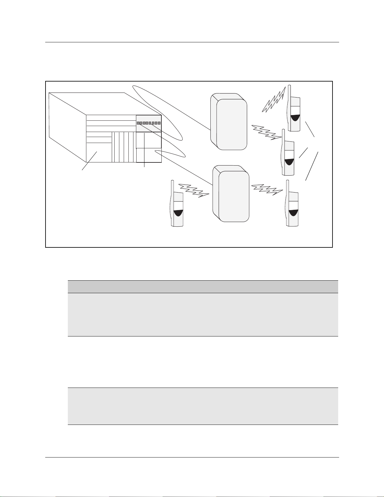
The following figure shows a graphic representation of the components of the system.
Figure 1 Integrated DECT service
Handsets
Base stations
Business
Communications
Manager
DECT media bay module
The following table describes the three main hardware components of the DECT system.
Table 1 Hardware components of the DECT system
Component Function
DECT media bay module The module connects up to eight radio base stations. Use the Business
Communications Manager Unified Manager application to initialize and
program the module.
Within the module, four BRI ISDN loops allow up to eight simultaneous
conversations. NOTE: Each Business Communications Manager system can
support one DECT module.
M6241 Radio base station Each base station provides radio coverage for a prescribed area. A group of
base stations make up a cell.
Each base station can support up to four simultaneous calls. The radio base
stations also offer antenna diversity.
Use the site survey to determine the number of base stations required to
cover the area. Refer to “DECT base station deployment planning” on page
22.
DECT cordless handset
C4010 and C4020
Each handset provides the user with telephony features remote from the land
set.
This book contains only the registration operations for the set. Refer to the
user manuals that came with your handset for operational details.
Up to 32 handsets can be assigned to each DECT system.
P0606013 02
Page 19

Chapter 1 DECT system overview and requirements 19
DECT features
The following list describes some of the special features of the DECT system.
• The DECT module contains f our BRI ISDN-S lo ops. The Busi ness Communic ations Manager
assigns four loop records in the Unified Manager when the module is installed, based on the
DIP switch settings for the module.
• The cordless handsets are identified with DNs in the Unified Manager. They can be assigned
answer DNs to link them with stationary sets.
• The numbering plan and call routing defined in the Business Communications Manager must
agree with the entries in the DECT interface.
Also refer to “Handset system features” on page 71.
Business Communications Manager features
The DECT system supports the following Business Communication Manager call processing
features:
• autodial keys (handset-based)
• answer keys
• busy lamp indication
• call capture
— incoming calls can be redirected to the prime set or a voice mail box
Note: DECT handsets only can only access voice mailboxes (FEATURE 981) and
receive only associated message waiting indicators (MWI) for new messages. Other
voice mail functions, Call Center features, Attendant Console, TAPI applications or
CTE applications are unavailable to DECT handsets. Symbol
handsets are the only portable system that supports these applications from the
Business Communic ations Manager.
— a system telephone calling a DECT handset will continue to ring even after the
handset ring timer runs out. It is recommended that all DECT handsets be set for Call
Forward No Answer to deal with this issue.
• call display when busy: handsets will only get a busy signal
• call forward (all calls, busy, no answer)
• call identification: available, depending on system programming
• class of service/dialing restrictions
• conference calling
• delayed Ring Transfer to Prime if the DECT handset is not answered
• dial external/outgoing line identi fication
• intercom lines
• external line access using line pool codes or destination codes
•hold
©
NetVision© wireless
DECT Installation and Maintenance Guide
Page 20

20 Chapter 1 DECT system overview and requirements
• hunt group functionalit y
• multiple line appearances
• on hook dialing
• private li nes (incoming)
• remote access
• ringing, restriction, and routing services
•set name
• target line (direct call from external line)
•transfer
• voice mail support to retrieve pending messages
Features not included on this list are not supported on the handset by the Business
Communications Manager system.
Handset features
These features are provided by the DECT handset, and are not necessarily exclusive to Business
Communications Manager operation.
• dial pad feedback
• feature access key
•headset
• hearing aid compatibility
• language choice
• last number redial
• on hook dialing from numbers stored in handset memory
• ringing line preference
• set speed dial
Refer to the D ECT documentation that c ame with the handset for details.
P0606013 02
Page 21
Setup process overview
The following figure provi des an overvi ew of the acti ons required to success fully set up the DECT
integrated system:
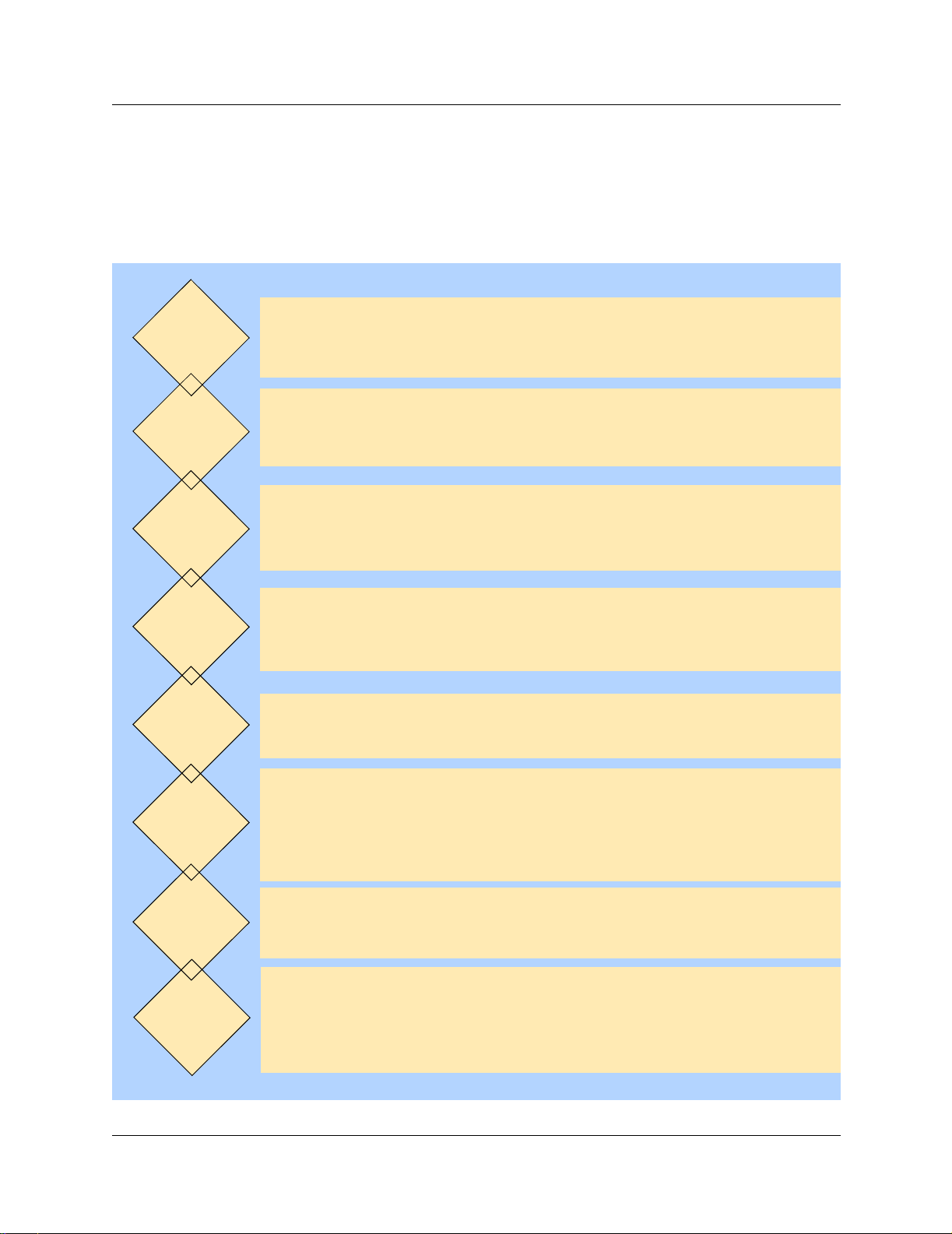
Figure 2 Setup process for the DECT system
Chapter 1 DECT system overview and requirements 21
Plan the
deployment
Check
BCM system
settings
Install
media bay
module
Install the
radio base
stations
Connect
base stations
to module
Have a site plan and deployment strategy worked out. Refer to the M6261DECT
Deployment Tool Guide on the Business Communications Manager CD.
Data report Site survey
Radio base stations locations Plan cells
Ensure that your Business Communications Manager has the correct Region
setting to allow DECT deployment. Refer to “Checking the System Region” on
page 30.
Refer to Chapter 2, “Installing the DECT media bay module,” on page 31.
This procedure assumes the Business Communications Manager is installed
and commissioned.
Refer to Chapter 4, “Installing the DECT base station,” on page 53.
Check the site map for obstacles and possible sources of interference to the
radio signal or data link.
The first radio base station must be within 800 m of the DECT media bay
module. Attach the components using 0.6 mm cable.
Program
the DECT
module
Subscribe
cordless
handsets
Maintenance
tools
Refer to “Configuring the DECT module” on page 37 for instructions about
setting up the module through the Unified Manager, and running the DECT
wizards. Chapters 6 to 8 provide instructions for manually configuring the DECT
module settings.
Refer to Chapter 5, “Subscribing DECT cordless handsets,” on page 61.
When the system and module DNs have been assigned, subscribe each
handset. Test the handsets with each base station.
For some functions, DECT works separately from other applications on the
Unified Manager. Use the tools found under the Maintenance button on the
first page of the Unified Manager to perform these functions: Time synch,
Firmware upload, Backup/Restore/Scheduling, Restore default, and viewing
the current Companding law setting.
DECT Installation and Maintenance Guide
Page 22

22 Chapter 1 DECT system overview and requirements
DECT base station deployment planning
The DECT base stations must be deployed to provide full site coverage with the maximum traffic
capacity, using the minimum number of base stations.
There are two tasks involved in arranging this:
• Surveying the site: the site survey involves gathering information t o determine customer
requirements and the number of cells needed to support the traffic.
• Planning deployment : deployment plans es tablish the best locations for t he radio base stations.
Site surveying and dep loy me nt pla nni ng a re complex tasks, undertake n only by trained person nel .
Refer to the M6261DECT Deployment Tool and site planning guide for detailed Site planning and
deployment.
DECT radio base station
The Business Communications Manager can support one DECT media bay module.
The information in this section includes:
• “External antennas” on page 23
• “Specifications for DECT radio base stations” on page 25
• “Base station notes:” on page 26
• “Description of the connection” on page 26
A cable attached to an RJ45 connect or in the f ace of the DE CT module connect s to the ba se stati on
RJ45 connector. This supplies the data and power.
The base station comes with two internal antennas to provide signal diversity. Some types of
external antennas can be substituted, depending on site requirements.
The following table describes the function of the parts of the base station.
Table 2 Parts of the DECT radio base station configurations
Part Description of function
Base stations The area covered by the base station depends on the radio range. Base stations
manage the links with the cordless handsets within that range.
Cables The cable includes two telephone pairs.
One transmits the signal.
One receives the signal.
Connectors The base station uses a female RJ45 to connect to the cable.
P0606013 02
Page 23
Chapter 1 DECT system overview and requirements 23
Table 2 Parts of the DECT radio base station configurations (continued)
Part Description of function
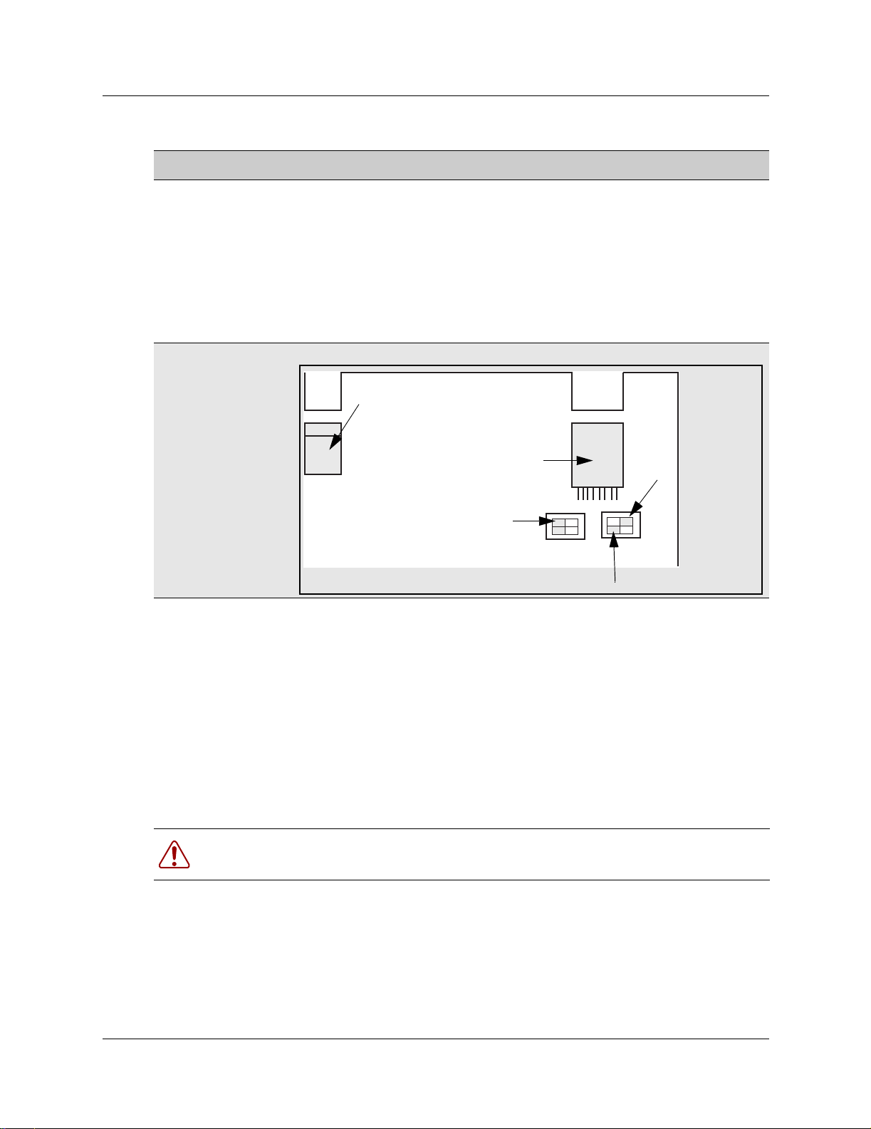
Switches There are two configuration switches: the CA1 and the S202.
• The CA1 has two switches, labelled 1/2 and 3/4.
Set 1/2 to On to enable the adaptation resistor for the synchronization pair.
Set 3/4 to On to enable base station Reset.
Set 3/4 to Off to run Reset by S0 interface level 1.
• The S202 has two switches, labelled 1/2 and 3/4.
Set 1/2 and 3/4 to On to enable the 100 ohm adaptation resistors for the S0
pairs.
Refer to Figure 3 on page 23.
Figure 3 Base station switches
Jack
Adaptation RNIS
External antennas
Three kinds of external antennas can be added:
• The MA431X23 is omnidirectional with an extension cord.
• The MA431X24 is omnidirectional with an extension cord.
• The MA821X12 is bidirectional with a 50-cm cable.
The HT6176A is an adapter for outdoor antennas.
Warning: Do not add any longer cables to the MA821X12, or the gain and receptivity
will suffer. Place this antenna as close to the base station as possible.
RJ45
4
3
S202
On
Adaptation synchronizer
2
1
4
3
On
Reset
2
1
CA1
DECT Installation and Maintenance Guide
Page 24
24 Chapter 1 DECT system overview and requirements
The MA431X23 and X24 antennas can be installed further from the base station. Ensure that the
coaxial cables linking the antennas with the base stations provide low attenuation. The following
figure illustrates two configurations:
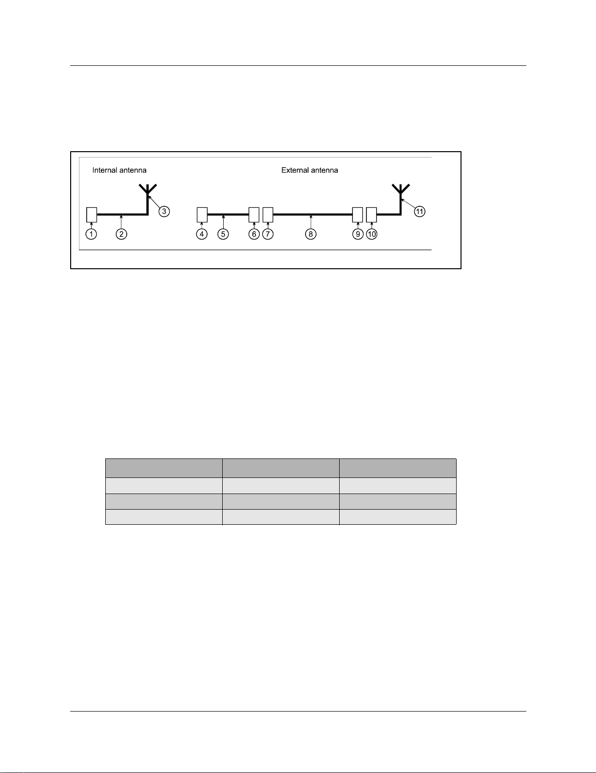
Figure 4 Antenna configurations
• The internal antenna inco rporates an MMS connector (1), on e coax ia l cable KX21 (2) and the
radiating element (3). The antenna gain is 2 dBi.
• The external antenna is connected via a cord (4-5-6) which incorporates an MMS male
connector (4), coaxial cable KX21 (5) and a TNC female connector (6). The manufacturer
specifies losses of less than the guaranteed dB value. Losses are actually of the order of 0.7 dB
at 2 GHz.
The extension cord conveying the signal to the antenna incorporates a TNC male connector
(7), low loss coaxial RG58cu cable (8) and N male c onnector (9). The antenna (11) is secured
to the extension cord using N female connector (10).
The losses generated by this extension cord ar e summarize d in the following table.
Table 3 Generated losses with extension cord added
Element Losses at Frequency Estimated losses
RG58cu 0.65dB/m at 2GHz
TNC 0.2 dB at 9GHz 0.1 dB
N 0.15 dB at 10GHz 0.1 dB
• The maximum length of the extension cord is 2.8 meters.
• The MA432X23 external antenna with an extension cord performs approximately in the same
way as an internal antenna, except for the polarization diversity.
• The MA432X24 provides a 2 dB gain compared to the internal antenna.
P0606013 02
Page 25
Chapter 1 DECT system overview and requirements 25
Specifications for DECT radio base stations
This section describes the radio base station specifications.
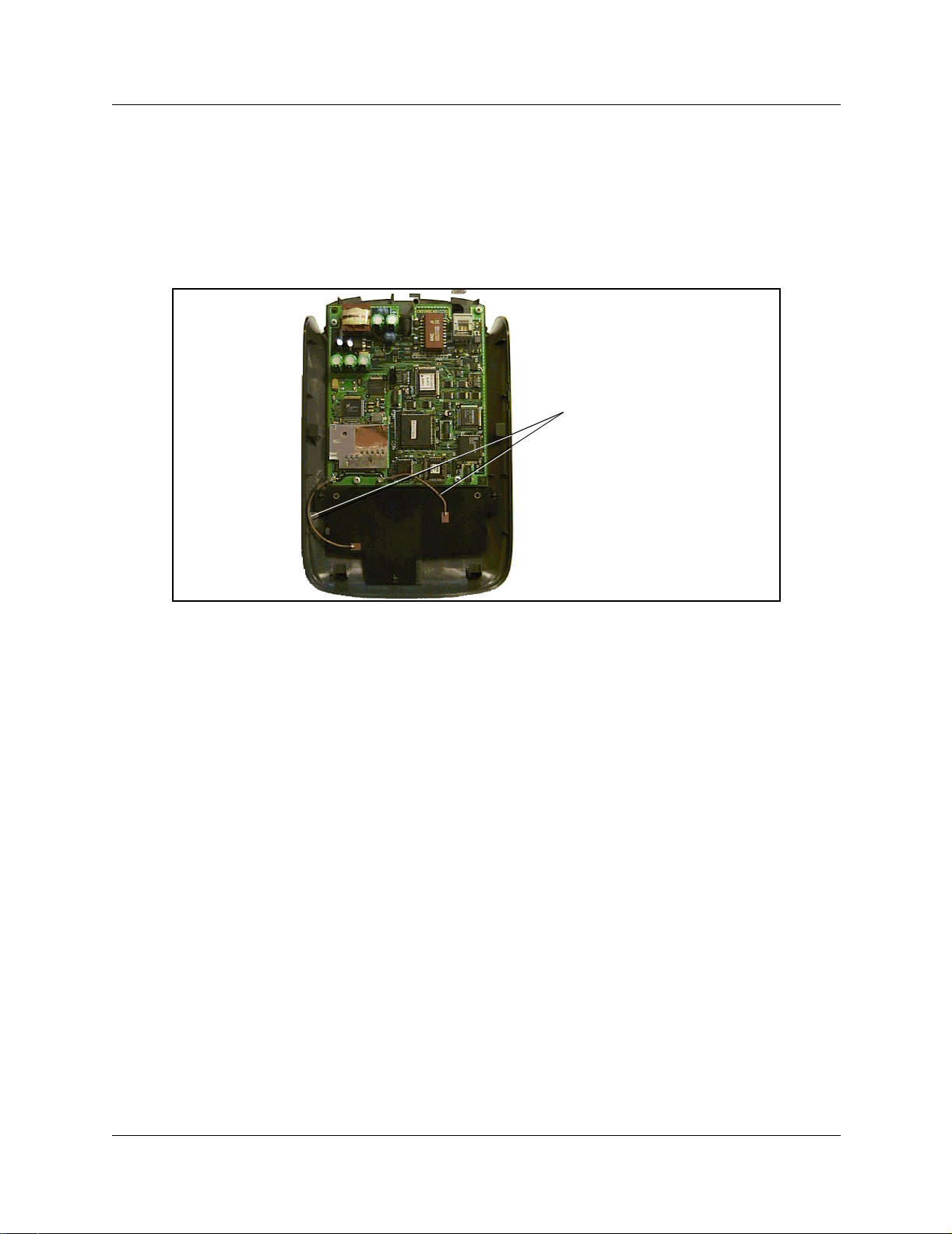
The following figure shows the base station with the top cover removed.
Figure 5 Inside the DECT radio base station
Internal antennas
The following specifications apply to DECT radio base stations:
frequency band: 1880 -1900 MHz
number of radio channels: 8
transmission power: 250 mw (peak)/10 mw (average)
instantaneous throughput of the channel: 1152 Kb/s
signaling channel throughput (D channel between
16 Kb/s
the module and the base station):
antenna type: omni-directional [one-way] or directional
integrated or external antennas
coverage range: from 10 to 30 metres (of fic e environme nt),
up to 300 metres (open air)
radio base station operating temperature: +5 to +45 degrees Celsius
number of simultaneous calls per radio base station: two or four
base station synchronization: yes
DECT Installation and Maintenance Guide
Page 26

26 Chapter 1 DECT system overview and requirements
Base station notes:
Here are some general-information notes about the base station:
• Do not install more than two overlapping radio base stations per cell.
• Do not apply any paint or other wall covering to the plastic shell without written approval
from Nortel Networks.
• Use the Unified Manager to perform resets of the base station.
• Signal processing f unctio ns for th e fou r -chan nel rad io base st atio n are ported to the media bay
module. In this case, the interface transports four 32 Kb/s ADPCM coded communications as
well as 16 Kb/s signaling channel.
Climatic conditions
The DECT base station can tolerate the following conditions:
Operational:
• Temperature: 5 to 45 degrees C.
- 20 to +60 with a special cabinet
• Relative humidity: 10 to 80%, not condensing.
Storage:
• Temperature range: - 10 to 60 degrees C.
• Relative humidity range: 10 to 90%, not condensing.
Power supply
The ISDN interface in the DECT media bay module enables the base stations to be powered
through the cable co nnec ti on between the DECT and t he bas e station. The remote p ower supply is
limited to 100 mA on the DECT interface, whi ch corr esponds to an avai lable power of 4 W at 48V.
The radio base station can also be powered using a local a.c./d.c. mains power supply unit,
PN 840 B. Use a local supply unit for no more than two radio base stations in any given cell.
Description of the connection
DECT base stations connect to DECT media bay modules using a cable containing two twisted
pairs. This cable connects to RJ45 connectors on the components. The connection at the DECT
position corresponds to an equipment number on the two cards on the DECT module that control
the base station interaction. If you assign specific base stations to equipment numbers, you must
ensure that base station is connected to the appropriate RJ45 jack on the DECT module.
P0606013 02
Page 27

DECT cordless handsets
Check for small metal o bject s in the DECT Handse t earp iece/ mouthpi ece b efore using t he
handset.
Do not store or locate flammable liquids, gases, or explosive materials in the same
compartment or vicinity as the cordless handset, its parts or accessories.
This section describes the features provided by the C4010 and C4020 cordless handsets. These
handsets were developed to work with DECT systems.
Other cordless handse ts ca n be u sed with the DECT sy stem. Th e s ystem featu res a vaila ble t o other
handsets depends on how the handset is configured, and how compatible it is with the signals
transmitted from the DECT module. As well, some features such as call display also require the
proper line configurations at both the local and telco end of the line.
Site configurations
Chapter 1 DECT system overview and requirements 27
Nortel Networks provides one PARI number on the DECT module that all the base stations share.
Access is authorized by ma tc hing the PARI number and the PARK number registered in the Other
multi-site configurations.
DECT call paths
The DECT module provides a telephony path separate from the Business Communication
Manager system. This means there are t hree possibl e paths for a ca ll to take.
• A DECT handset-to-ha ndset cal l is r outed fr om the cal ling ha ndset, th rough the DECT module
C8 interface, into the receiving handset.
• A DECT handset-to-Business Communications Manager set call is routed from the calling
handset, into the C8 interface, and into the Business Communications Manager. The Business
Communications Manager then routes the call through the appropriate station module to the
receiving set.
• A DECT handset-to-external cal l is routed from the calling handset, into the C8 interface, and
into the Business Communications Manager. The Business Communications Manager then
routes the call through the appropriate trunk module out to the public network. This is the
same route a call fr om a DECT handset to a set o n a privat e network wou ld use. The dif ference
is that the user enters a different destination code.
• If a DECT handset transfers a call, the DECT C8 processes the transfer and creates a new call
destination. The call remains routed through the C8 interface, even though the DECT handset
is no longer involved in the call.
DECT Installation and Maintenance Guide
Page 28
28 Chapter 1 DECT system overview and requirements
DECT programming overview
Here are some important points about using DECT on your Business Communications Manager.
• The Business Communications Manager must be configured with a region setting that
provides DECT support.
Note: Valid DECT region settings:
Australia, Denmark, France, Germany, Global, Holland, Italy, Norway, Spain, Sweden,
Switzerland, Taiwan, United Kingdom
• The system default password is set to
insta. You can delete or change this password to suit
your needs.
• Default language is English.
• Disable the base stations before a firmware u pgrade. Put the base stations back in service in
sequence.
• To subscribe handsets, a base station must be set to accept handset recording.
• The handset DN must also be set into recording mode before the handset can be subscribed.
• The system uses data links.
• Within the DECT interface, numbers enclosed in ( ) indicate length of parameters. Refer also
to “DECT interface commands” on page 28 and “Numbering plan syntax” on page 29.
Note: Refer to the Business Communications Manager Programming Operations Guide
to configure telephony parameters for each handset DN.
DECT interface commands
The following table shows the main commands that are needed to navigate the DECT interface.
Table 4 DECT interface commands
Command Explanation
Ctrl U Goes to main menu.
Ctrl J Moves up one level of menus.
space bar Toggles between items within screens.
Esc (alpha commands) ESC M = more
Del Deletes item backwards.
Note: Data changes take effect immediately! There is no UNDO option.
P0606013 02
A list displays at the bottom of each screen.
Page 29

Chapter 1 DECT system overview and requirements 29
Numbering plan syntax
The following table explains how the syntax for the numbering plan works:
Table 5 Numbering plan syntax
Number Plan width Entry Means
(2) 1-2 10 to 29
(3) 12-3 120 to 139
(5) 1623-4 16230 to 16249
(5) 1-2 10000 to 29999
Business Communications Manager requirements
The DECT system only works with a Business Communications Manage r system that has been set
to a compatib le region. R egion settings determine basic syst em compatibilities with l ocal
telephony protocols. Confirm the region on your Business Communications Manager before you
attempt to install the system. Regions are discussed in the Business Communications Manager
Programming Operations Guide.
This book describes the handset direc tor y numb er (DN) sys tem base d on the default setup, where
the Start DN is 221 and the DN length is three digits. If your system has a different DN structure,
use the tables provided to translate the DNs listed to match those of your system.
Examples of DN structures:
If your Start DN is 221 but you require a five-digit DN, the system automatically creates a Start
DN of 22221 when you specify a five-digit DN at startup.
If your Start DN needs to start with a specific number, change the Start DN after you specify the
DN length at startup. For instance, if your Business Communications Manager is part of a CDP
(Coordinated Dialing Plan ) netw ork wit h fiv e-digi t DNs, yo ur sys tem must have a u niq ue first DN
digit, so you would specify the exact Start DN, in this case, something like 31111.
DECT Installation and Maintenance Guide
Page 30
30 Chapter 1 DECT system overview and requirements
Checking the System Region
If you experience problems configuring the DECT module on your system, check the region for
which the system is set.
Note: DECT systems can be installed in countries that can run the following region
profiles: U K, Australi a, Sweden, D enmark, Holland, Nor way, Italy, Germany, Spain,
Switzerland, France, G lobal, Taiwan.
Refer to the Business Communications Manager Programming Operations Guide
appendices for the table that lists all the region s.
Caution: You must select a region that reflects the geographical location of the
Business Communications Manager.
If you choose the inco rrect region, th e Business Communicat ions Manager syst em does
not communicate correctly with the Public Switched Telephone Network.
This procedure describes how to ensure that the Business Communications Manager is set to the
correct region for the DECT module.
1 Open the Unified Manager for your Business Communications Manager system.
2 On the navigation tree, click Diagnostics/MSC.
3 On the top menu, click on Configuration.
4 Click System startup.
5 Ensure that the Region box displays the correct region.
Warning: If you reset the region profile on the Business Communications Manager, the
system is reset to default parameters. Therefore, ensure that you have a current backup
before you attempt to do this procedure.
Note: When you select a new region, the Template box is disabled. You must restart the
system before the templates for the selected region are available.
a To change the region, select a region from the list.
b Click OK to apply these changes.
The system displays a warning that th e system will restart and that the default
programming values will be restored.
c Click Cold Start to restart the Unified Manager.
6 Continue with the DECT deployment.
P0606013 02
Page 31

Chapter 2
Installing the DECT media bay module
This section describes how to install the DECT media bay module in the Business
Communications Manager. The following flow chart shows an overview of the process.
Figure 6 Process for installing the DECT module
Site
planning is
complete
31
Base stations are
installed
Note the PARI number
on the side of the
module
Set the DIP switches
on the back of the
DECT module
Prepare system for
shutdown
Shut down the system
Remove the front bezel
Remove the media
bay cover
Install the DECT
module
Restore system to
operation
Go to Chapter 3,
“Configuring the DECT
module,” on page 37 to
perform the module
identification and
initialization.
DECT Installation and Maintenance Guide
Page 32

32 Chapter 2 Installing the DECT media bay module
Setting the DIP switches
This procedure describes how to set the DIP switches for the DECT media bay module.
Ensure that you wear equi pment t o prope rly gr ound yo ursel f whil e handl ing an y of
the electronic parts to this system.
1 Take the media bay module from its box.
2 Inspect the module for damage.
3 Make a note of the PARI number, which is located on a label on the module.
4 Determine which DS30 channel (bus) number to use for the module.
Note: Remember t hat t he bus you choose cann ot conf lict with a l ocati on alr eady as signe d
to an existing media bay module.
Use Bus 6 or 7 if they are available.
5 Set the DIP switches, located on the back of the DECT module to the DS30 channel number.
Set the offset to 0 (on).
The following figure shows the location of the DIP switches on the DECT module.
Figure 7 Locating the DECT media bay module dip switches
On
1 2 3 4 5 6
Off
P0606013 02
Page 33

Chapter 2 Installing the DECT media bay module 33
• The following table shows the switch settings for each DS30 channel number. The offset
number is always 0.
Table 6 DECT switch settings
off
Use these
DNs on new
2.5 or
greater
systems
597-624* 501-532*
597-624* 501-532*
597-624* 501-532*
597-624* 501-532*
597-624* 501-532*
597-624* 501-532*
Use these
DNs on
updated 2.0
system
**Customized DN
range
Set the switches
Select
DS30
channel
2 0
3 0
4 0
5 0
6 0
***7 0
*If you need more DNs, use DNs in the portable DNs, starting at 565. Ensure no other devices are assigned
to these DNs before you use them.
**Note: The extensions listed are based on a three-digit DN with a Start DN of 221. If your system has longer
DNs or a different Start DN, enter the range in the blank column.
***If your system has a 3/5 DS30 channel split, channel 7 is not available to media bay modules. Refer to the
Business Communications Manager Programming Operations Guide for further information on this feature.
Select
offset
Offset DS30 channel
123456
on on on on on on
on on on on on
on on on on on
off
on on on on
off off
on on on on on
off
on on on on
off off
Note: If you replace a module, set the DIP switches for the new module to exactly the
same settin gs as the removed module.
TIP: Numbering conventions:
This document assumes three-digit DNs, starting with a Start DN of 221. If your system
has a differe nt number ing pl an, adjust the numberin g accor dingl y. If you follow a diffe rent
numbering plan, ensure that you update all the DN settings described in Chapter 8,
“Programming DECT handset records,” on page 93.
Use the following table to note the settings you chose.
Table 7 Module settngs
Module PARI number:
DS30 channel:
DIP switch settings:
Notes:
DECT Installation and Maintenance Guide
Page 34

34 Chapter 2 Installing the DECT media bay module
Installing the DECT module
After you have set the DIP swi tches, you ca n install the module. You need to shut down th e system
to install the module, therefore, choose a period when the Business Communications Manager is
not busy.
Remember to warn users that the system will be down for a short period.
1 Ensure the Business Communications Manager base unit is properly shut down.
Danger: Failure to follow these steps can result in damage to the system or the
module.
a From the Unified Manager application, click System, then go to the Logoff menu and
click Shutdown.
For detailed shutdown information, refer to the Business Communications Manager
Programming and Operations Guide.
b Disconnect all the cables from the front of the Business Communications Manager base
unit and expansion unit, if there is one.
c Disconnect the base unit and expansion unit power cords from the a.c. outlet.
d Remove the front bezel from t he fr ont of the base un it or e xpansi on unit where you pl an to
install the DECT module.
2 Remove the blank cover from the module bay.
To remove the bay cover, pull the tab beside the module bay. This pushes the cover forward.
The following figure shows the module release tabs on the base unit and expansion unit.
Figure 8 Release tabs for the module bays
Business Communications Manager base unit
Business Communications
Manager expansion unit
Media bay coverplate
and module release
tabs
P0606013 02
Page 35

Chapter 2 Installing the DECT media bay module 35
3 Insert the module into the open bay and push until the module clicks into the backplate.
Note: The module protrude s sligh tly. After the front bezel is replace d, the fac e of
the module sits flush wi th the front of the unit.
4 Replace the front bezel on the base unit or the expansion unit.
The following figure shows the base unit and expansion unit with the front bezels replaced.
Figure 9 Front bezels replaced on units
Business Communications Manager base unit
Bezels replaced on units
Business Communications
Manager expansion unit
5 Refer to the following section to restore the system.
Restoring the system
After the module is installed, restore the Business Communications Manager operations. Then
connect the base station cables to the module.
Warning: Failure to properly reconnect the system, as described in this
procedure, can result in damage to the system or the module.
1 Inspect the system to ensure all components are in place.
2 Reconnect the a.c. power cords for the Business Communications Manager base unit and the
expansion unit, if there is one.
3 Reconnect all the connections to the front of the units.
4 Monitor the LEDs on the front of the DECT module to ensure the system reboots properly.
Refer to the following figure. This process takes a few minutes.
— Power (working status)
— Status (hardware status)
— Run (CPU of the DECT C8 interface) (blinks when stable)
DECT Installation and Maintenance Guide
Page 36

36 Chapter 2 Installing the DECT media bay module
— 48 V for the base station jacks
Figure 10 Locating the LEDs on the DECT module face
Power LED
Status LED
Run
Base station power
5 When the power and status LEDs on the module are solid green, you are ready to continue
with the module config ura ti on. Ref er to Ch apt er 3, “Conf ig uri ng t he DECT module,” on page
37.
If the lights are off or are blinking, refer to “Monitoring the DECT module LEDs” on pa ge 1 14
for troubleshootin g infor mation.
P0606013 02
Page 37

Chapter 3
Configuring the DECT module
There are some preli minar y s te ps that you must do with in the Business Communications Manager
Unified Manager application before you run the wizard that configures the DECT module. This
section describes how to ensure that the Business Communications Manager system sees the
DECT module. It also describes how to find and manage the DNs designated for DECT handsets.
When the Unified Manager set tings have be en done, yo u can ru n th e DECT Configu ration wi zard.
This wizard configures the DECT module. It also turns on one of the base station ports to allow
handset subscription.
Handset subscription (mobile recording) can also be turned on and off using the DECT Mobile
Recording (handset subscription) wizard, which is described in “DECT Mobile Recording
(Handset Subscription) Wizard” on page 63.
This section contains the following headings:
• “Process overview: Identify and configure the DECT Module” on page 38
37
• “Confirming the DECT module” on page 39
• “Configuring the module for µ-law” on page 40
• “Checking the Unified Manager handset DNs” on page 43
• “Setting up the handsets” on page 44
• “About the DECT Wizards” on page 47
DECT Installation and Maintenance Guide
Page 38

38 Chapter 3 Configuring the DECT module
Process overview: Identify and configure the DECT Module
The following figure describes the steps you need to take to identify and configure the DECT
module.
Figure 11 Process for identifying and configuring the DECT module
Identify the
DECT
module
Choose
handset
DNs
Run the
DECT
Config.
wizard
Set
module
time synch
Connect
base
stations to
module
Ensure the Business Communications Manager recognizes the DECT
module. Change firmware if the module requires
µ-law ISDN protocol.
Refer to “Configuring the module for µ-law” on page 40.
These DNs must match the DNs you enter on the DECT interface.
Use the default DNs, unless your system requires a different numbering
scheme.
Refer to “Setting up the handsets” on page 44.
The DECT Configuration wizard sets up the DECT module, using the
default DNs you specified. Refer to “Using the Configuration Wizard” on
page 49.
After you run the Wizard, ensure that the module is time synched with
After you run the Wizard, ensure that the module is time synched with
the Business Communications Manager.
the Business Communications Manager.
Refer to “Setting up the module Time Synch” on page 50.
Refer to “Setting up the module Time Synch” on page 50.
After the configuration wizard is complete, connect the base stations to
the module and subscribe the handsets.
Refer to “Connecting the base station to the system” on page 56, and
Chapter 5, “Subscribing DECT cordless handsets,” on page 61.
P0606013 02
Page 39

Confirming the DECT module
After the DECT module has been installed and the system has rebooted, you must identify the
module to the Business Communications Manager system.
Use this procedure to ensure the system recognizes the module type.
1 On the navigation tree, click the key beside Resources.
2 Click on Media Bay Modules.
3 Click on the Bus number for the DECT module.
4 Ensure that Programmed Bus Type is set to Trunk Module.
5 Click the key beside Modules on Bus.
6 Click on Module 1.
7 Ensure that Module Type is set to DECT.
8 If you made changes to any of the module settings, do the following, otherwise continue with
step 9:
Chapter 3 Configuring the DECT module 39
a Click on the DECT module Bus.
b On the top menu, under Configuration, choose Disable.
c On the message box, click OK.
d On the top menu, under Configuration, choose Enable.
When the module is enabled, the State field read s: equipped.
9 At the bottom of the Resources list, click on the DECT heading.
10 Confirm the module name, or select the correct module.
Note: If the module does not immediately appear on the list, wait a few minutes and try
again.
This module type only appears when a DECT module is present on the system. If
the DIP switches are set incorrectly, the setting will appear, but the module will
show as unequipped.
Note: Companding law requirements.
The DECT module defaults to a-law. If your system requires the µ-law ISDN protocol,
refer to “Configuring the module for µ-law” on page 40 for instructions a bout re setting t he
module.
DECT Installation and Maintenance Guide
Page 40

40 Chapter 3 Configuring the DECT module
Configuring the module for µ-law
The Business Communications Manager has the software for both µ-law and a-law ISDN
protocols. The system defaults to a-law, as does the DECT module. To change this setting on the
DECT module in countries where µ - law is required, you need to upload a new set of firmware.
Follow the directions in this section to set up the module and upload this firmware.
Caution: This procedure resets the DECT module settings to the default settings, so it
must be done before you run the DECT wizard.
If your system uses the a-law protocol, skip to “Checking the Unified Manager handset DNs” on
page 43.
Before you start
Ensure that the following has been done before you attempt to upload new firmware to the DECT
module.
1 Ensure that the Business Communications Manager system has been initialized with the
correct µ-law Region profile. Refer to “Checking the System Region” on page 30.
2 If you are unsure of what your DECT module is set to, you can check the setting through the
DECT module. Refer to “Determining module companding law setting” on page 115.
3 To view the companding law for the firmware that is ready to be loaded, you can check under
DECT T ools . Refe r to “Set ting up the DECT fil e for upl oad” on pag e 41 fo r a detai led pr ocess
for finding the DECT Tools pages under the Maintenance button on the first page of the
Unified Manager.
4 On the DECT Tools page, click the Companding Laws link.
The resulting page shows the current setting for the DECT firmware load that will be loaded
onto the module.
P0606013 02
Page 41

Chapter 3 Configuring the DECT module 41
Setting up the DECT file for upload
The first st ep is to set up the file that n eeds to be uploaded by the module.
1 On the Unified Manager first page, click on the Maintenance button.
2 On the left menu of the maintenance site, click on Maintenance tools.
The following menu appears.
Figure 12 Maintenance Tools menu
3 Beside the DECT heading, click on the Firmware Upload link.
The firmware upload page appears.
DECT Installation and Maintenance Guide
Page 42

42 Chapter 3 Configuring the DECT module
Figure 13 Firmware upload
4 Beside Please enter your DECT installer Password, type: insta*
Note: *The Password listed here is the default. Your system settings may have been
changed.
5 Click the Execute DECT Firmware Upload button.
The upload screen appears and remains until the upload is complete.
Note: The log file notes if the upload is successful. If the upload fails, go back and
ensure that you have the correct DECT password.
Resetting the module to default values
Now you must reset the module to default values.
1 You should still be in the DECT Tools section.
2 Click on the Restore Default Configuration link.
The Restore Default Firmware page appears.
Figure 14 Restore default firmware configuration
3 Beside Please enter your DECT installer Password, type: insta*
P0606013 02
Note: *The Password listed here is the default. Your system settings may have been
changed.
Page 43

Chapter 3 Configuring the DECT module 43
4 Click on the Restore Default Configuration button.
5 The restore default configuration operation begins.
Note: The log file notes if the upload is successful. If the upload fails, go back and
ensure that you have the correct DECT password.
6 Once this step is complete, you are ready to set up the Business Communications Manager
records and run the DECT Config uration wiz ard and time sync h proces ses, as de scrib ed in the
following sections of th is chapter.
Checking the Unified Manager handset DNs
The DECT handset is considered an ISDN S device. Assign the handset to DNs within the default
ISDN and DECT range. Ensure that you do not assign handset DNs that have already been
assigned to other ISDN devices.
Note: Default DECT module DNs:
• New 2.5 and greater Business Communications Manager: 597-624
• Upgraded 2.0 Business Communications Manager: 501-532
These defaults assume a system with a three-digit DN structure, and a Start DN of 221. If
your system is different, use these numbers as guidelines to find the defaults to your
system.
Note: If you need more DNs than are available in the default range, use the
Companion DNs. Ensure these DNs are available before assigning them, then
choose ISDN and DECT for the DN Ty pe field.
Warning: It is imperative for the DECT module programming, that the DNs for your
DECT handsets are within a range of DNs. If you assign handsets to DNs outside of a
range, use the DN Renumber Wizard to renumber the DNs on the Business
Communications Manager to create a range. Make sure you do not overwrite any DNs
already in existence when you do this.
The issue: The DECT media bay modu le prog rammi ng onl y ha s 12 l ine s t o accommodate
handset DNs, therefore, if you specify more than 12 individual DNs, and try to run the
DECT Quick Start Wizard, the Wizard will fail.
Note: If you want to id entify the h andsets wi th the CO li ne number as signed to them, en ter
this number in the Name field for the DN record assigned to that handset.
DECT Installation and Maintenance Guide
Page 44

44 Chapter 3 Configuring the DECT module
To check the handset records in the Unified Manager, follow these steps:
1 Open the Unified Manager.
2 From the menu, click BCM, Services, Telephony Services, System DNs,
All ISDN/DECT DNs.
3 Click on the DN number you want to assign to the handset.
4 Under the DN number, click General.
5 When the General screen appears, ensure that the DN Type displays ISDN and DECT.
6 Repeat for all handset DNs.
7 Refer to “Setting up the handsets” on page 44 for infor mation abou t setti ng up the DN record s.
8 When the records are set up, run the DECT Configuration wizard. Refer to “Using the
Configuration Wizard” on page 49.
9 The configuration wizard also sets up the system to start subscribing handsets.
10 To turn off handset subscription (mobile recording), run the DECT Mobile Recording
(Handset Subscription) wi za rd. Refe r to “DECT Mobile Recording (Handset Subscription)
Wizard” on page 63.
Check the DNs against the DECT module DNs. Refer to “Listing mobiles (handsets)” on page 97.
Setting up the handsets
How you want to use the DECT handset will determine how you set up the handset DN record.
This section describes the ways the handsets can be used.
Detailed configuration information is contained in the Business Communications Manager
Programming Operations Guide.
The DECT cordless handse ts eith er can be s et to ri ng in tande m with a sta tionary s et, or conf igured
to act as stand-alone sets. As well, the handsets can be configured as target lines to accept direct
inward dial (DID) calls.
This following sections explain the Unified Manager settings required for each type of scenario.
• “Stand-alone handset” on page 45
• “Assigning handsets to fixed telephone DNs” on page 46
• “Handset feature programming” on page 46
P0606013 02
Page 45

Chapter 3 Configuring the DECT module 45
St and-alone handset
A stand-alone set can be configured to only receive calls, or to both send and receive calls
internally or externally.
Internal calls: The DECT interface comes with a set of default DNs. After the handsets are
registered to these DNs, and the DNs are acti vated, the handsets c an be used to ma ke calls be tween
sets.
After the DECT handset DNs are added to the Unifie d Mana ger, the handsets can be used to make
and receive calls internal to the Unified Manager system.
External calls: The handset can be configured to have full send and receive capability to the
public switched telephon e netw ork (PSTN), or, by using a target line, can be configured to re ceive
calls only.
Assigning routes or lines
The Unified Manager aut omatically assigns all DNs with the d efault Pool A. This automatically
allows calls thr ough t his l ine pool. T his l ine p ool c an be delet ed, an d o ther pools added, depend ing
on your requirements. Since the DECT handset does not have any line buttons, the user needs to
know the line pool access codes or destination code that accesses any lines and line pools that are
assigned to the handset record.
Follow these steps to assign a line pool to the handset record:
1 Open the Unified Manager.
2 On the navigation tree, click BCM, Services, Telephony S ervices, System DNs,
All ISDN DECT DNs, DN ##, where DN is the DN of the DECT handset.
3 Ensure you have a line pool set up that you want to use.
4 Click Line Pool Access and click the Add button at the top of the column.
5 Click the line pool you want the handset to use to make and receive calls.
6 Repeat as necessary.
Assigning target lines
If you want the handset to receive incoming calls dialed using the handset DN, set up a target line
for the handset. If you wan t the us er to on ly rece iv e call s on the h andset , set up a t ar get line an d no
other lines for the telephone.
Note: If you do not want the user to be able to di al out at all, ens ure that no oth er lin es or
line pools are assigned to the handset.
DECT Installation and Maintenance Guide
Page 46

46 Chapter 3 Configuring the DECT module
1 Open the Unified Manager.
2 On the navigation tree, click BCM, Services, Telephony Services, Lines, Target Lines.
3 Click a target line number heading that is not already assigned.
4 Click on Trunk/Line data.
5 Click on Received Number.
6 Enter the handset DN number.
7 On the navigation tree, click Services, Telephony Services, System DNs,
All ISDN/DECT DNs, DN <handset DN>.
8 Click on Line Access, Line Assignment.
9 Click the Add button at the top of the navigation tree.
10 Add the line number of the target line in Line field.
11 Click Save.
12 Click on the Line <target line number> heading.
13 Ensure Appearance is set to Appr. & Ring.
Assigning handsets to fixed telephone DNs
You can also associate each handset with a fixed telephone by assigning the handset with an
Answer DN for the fixed telephone. With this feature, the handset rings whenever the fixed
telephone rings. If you want more than one telephone to ring at the handset, call forward the
telephones to the handset DN.
1 Open the Unified Manager.
2 On the navigation tree, click BCM, Services, Telephony S ervices, System DNs,
All ISDN/DECT DNs, DN ##, where DN ## is the DN you want to assign to the handset.
3 Click on the key beside Line access.
4 Click Answer DNs.
5 Enter the DN number for the fixed telephone you want to associate with the handset.
6 Press <Tab> to update the record.
7 Repeat this process for all handsets you want to assign.
Handset feature programming
The call features available to DEC T handsets are described in “Handset system features” on page
71. Programming for these features is the same as for other Business Communications Manager
telephones w ith these fea tures. Refer to the Business Communications Manager Programming
Operations Guide for i ns tr uctions. Refer to t he handset user manual for instructions on how to use
the features.
P0606013 02
Page 47

Chapter 3 Configuring the DECT module 47
About the DECT Wizards
These wizards will lead you through the necessary procedures to configure your DECT module
and set up the module for subscribing the handsets.
If you need to cha nge any of th ese sett ings a fter the wi zards are r un, ref er t o th e spec ific proce dure
described in the following sections:
• “Understanding the DECT Configuration Wizard” on page 47
• “Before you start” on page 47
• “Using the Configuration Wizard” on page 49
• “Setting up the module Time Synch” on page 50
• “DECT Mobile Recording (Handset Subscription) Wizard” on page 63
Understanding the DECT Configuration Wizard
Use this wizard to per for m the initial configurat i on of a DECT module and to set up a base station
to allow handsets to be subscribed to the syst em.
The wizard collects current information about the DECT settings from the Business
Communications Manager, and sends them to the DECT module. None of this information
displays on the screen, except for the ISDN or DECT DNs.
Warning: Use this wizard ONLY for initial configuration, as it wipes out any previous
DECT module information.
To ensure you have the correct information and settings to run the wizard, refer to the Before you
start section, below.
Before you start
The following conditions are required before you run this wizard.
• The telephony (DNs and line access), routing information, and any line pool access coding
must be co nfigured on the Business Communications M anager.
Note: Any changes made after the wizard is run will not be reflected on the DECT
module. This is an instance where you would need to go directly into the module
settings and check or adjust the settings.
• The DECT module companding law has been correctly set for your region. Refer to
“Configuring the module for µ-law” on page 40.
• The DECT module must have the factory default settings applied to it. If these have been
changed in any way since the module was installed, you can reset the module through the
wizard.
DECT Installation and Maintenance Guide
Page 48

48 Chapter 3 Configuring the DECT module
• You must ensure that the Business Communications Manager recognizes the DECT module.
Refer to “Confirming the DECT module” on page 39.
You need to know the following information before you run this wizard:
• Do you want to reset the DECT module to the factory
default settings?
• What is the PARI value that you copied off the side of the
DECT module before it was installe d?
• How do you want to identify the DECT module? (Install Name)
No Yes
(PARI value)
• Which base station do you want to enable to allow
terminal subscription?
Refer to “Identifying base stations” on page 94 for more
information about numbering.
• How many handsets will you be subscribing?
Which DNs are assigned to these handsets in the Unified
Manager?
• Do you want to enable Call Waiting?
This setting allows you to turn the Call Waiting feature of f
or on for your DECT handsets.
Choosing No disall ows more than one call to the handset.
Anyone trying to call a h andset that currently has an
active call will receive a busy tone.
Choosing Yes allows a second call to alert on the DECT
handset. The user on the active DECT handset hears a
beep to indicate that a call is waiting.
The user presses:
• R*5 to answer the call
• R2 to toggle between calls
• R1 to return to the original call and disconnect the second call.
(base station)
6-0 6-1 6-2 6-3
7-0 7-1 7-2 7-3
(DN number)
Ye s (e n ab l e )
No (no handset assigned)
(Enable Call Waiting)
Yes (enable second call capability)
No (disable second call capability)
Refer to “Using the Configuration Wizard” on page 49 for the steps about how to run the wizard.
P0606013 02
Note: The Business Communications Manager provides up to 28 ISDN/DECT DNs. If
you require more handsets, or if some of the DNs are already used for other
equipment, you can change the DNs in the Companion range to ISDN/DECT.
This must be done before you run the Wizard, as the wizard only rec ogni ze s DNs with the
ISDN/DECT label. Refer to “Checking the Unified Manager handset DNs” on page 43 for
more information about default DNs.
Page 49

Chapter 3 Configuring the DECT module 49
Using the Configuration Wizard
Wizards are accessed through the Wizard button that appears on the first page of the Unified
Manager.
Warning: Ensure there is no one else using the Unified Manager when you run wizards.
Follow these steps to fill out the wizard:
1 On the first page of the Unified Manager, click the Wizards button.
2 You will be prompted to enter a User Name and Password. You must enter an
administrator-level user name and password.
A new page appears, displaying all the wizards that can be used for the Unified Manager.
3 Click on the DECT Wizard button for the task you want to perform.
If the system does not recognize the DECT module, these buttons do not appear. Refer to
“Before you start” on page 47.
4 On the first page (General), specify the DECT module information and the base station that
you want to turn on to allow handset subscription. If you choose None, then handset
subscripti on for all base stations is turned off.
5 Click the Next button to move to the next page.
6 On the second page, determine which DNs will be assigned to handsets.
7 Click the Next button to move to the third page.
8 On the third page, check the summary, which includes list of the DNs you selected.
9 Click the Apply button on the screen to invoke the wizard.
10 After the wizard succes sfully runs, refer to “Setting up the module Time Synch” on page 50.
DECT Installation and Maintenance Guide
Page 50

50 Chapter 3 Configuring the DECT module
Setting up the module Time Synch
After you run the Configuration Wizard, you need to ensure that the module time is synchronized
with the Business Communications Manager. Since the module time can drift out of synch, you
can use this BRU tool to set up a schedule for daily time synchronization.
The time can also become unsynchronized if you perform firmware uploads. Also, if you change
the password, you must re-establish the time synch schedule.
Follow these steps to set up a time synch schedule:
1 On the Unified Manager first page, click on the Maintenance button.
2 On the left menu of the maintenance site, click on Maintenance tools.
3 In the Maintenance Tools box, beside the DECT heading, clic k on th e T i me Synchronisation
link. The DECT Time Synchronisation Manager page appears.
Figure 15 Time synchronisation page
4 If there is no currently-scheduled time synchronisation scheduled (top frame), fill out the
fields to indicate when you want time synchronisation to occur for the DECT module.
P0606013 02
Page 51

Chapter 3 Configuring the DECT module 51
5 Beside Please enter your DECT installer Password. The default password is insta*.
6 Click on the Schedule a DECT Time Synchronisation button.
DECT Installation and Maintenance Guide
Page 52

52 Chapter 3 Configuring the DECT module
P0606013 02
Page 53

Chapter 4
Installing the DECT base station
This chapter desc ribes how to i nsta ll th e DECT base stat ion ac cor ding t o the d eploymen t s ite p lan.
Ensure that you have a complete deployment and site plan before you attempt to install the base
stations.
Installing base station hardware
This section describes how to install the base station hardware.
Use only qualified personnel to install or maintain the DECT radio base stations.
Special considerations
There are a number of considerations you need to take into account before you install a base
station:
53
• Base stations must be positioned exactly where indicated on the site mapping plan. Any
changes can affect tran smission and receptio n.
• Avoid installing base stations on metallic surfaces or load-bearing walls made of reinforced
concrete. If a metallic surface cannot be avoided, use a 50- to 80-cm extension bracket. Metal
can impair transmission and reception.
• Place the base stations less than four meters from the ground. This makes it easier to maintain
the base station and ensures correct radio coverage. Do not place stations lower than two
meters.
• Do not install the base station behind obstructions, such as false ceilings.
• Always hang the base station in a vertical position.
• Leave at least 30 to 50 cm between co-located base stations.
• Install outdoors base stations in sealed cabinets.
• Leak-tight cabinets (reference DECT052) let you install DECT radio base stations outdoors
without an external antenna. A mounting kit (reference DECT055) lets you secure the leak
tight cabinet to a pole.
Note: T wo base sta tions positioned side by side incr ease the channe l capacity fr om four to
eight possible simultaneous calls. Tandem base stations must be placed exactly 85 cm
from each other. They also must be part of the same cell and trunk group.
• If you are using external antennas, refer to “Base station antennas” on page 58.
DECT Installation and Maintenance Guide
Page 54

54 Chapter 4 Installing the DECT base station
Installing the base station on the wall
Follow these steps to properly attach the base station to the wall.
Ground yourself with an antistatic grounding strap before performing procedures
inside the base station housing
1 Locate the base stations according to the site survey and deployment infor mation.
Position the base stations at the exact point determined by the deployment survey. Moving the
base station by one or two meters can harm transmission and reception.
2 Slide the cover of the base station upwards, then pull it away from the back panel.
The following figure shows the base station without the cover.
Figure 16 Base station with cover pulled away
.
Screw holes on base station
3 Screw the back panel of the radio base station to the wall.
• Use two 3.5 x 25 mm wood screws wi th ra wplugs. I nsert the sc re ws thro ugh the two hole s
located at the top end of the back plane of the base station.
• Install base stations vertically. Provide the required 5 cm (2-in.) clearance around the
module for subsequent maintenance operations, as necessary.
P0606013 02
Page 55

Chapter 4 Installing the DECT base station 55
Base station connections
Avoid sources of interference. Machines and wires can cause interference. Use the information in
the following table as a guide for laying out the Business Communications Manager cable to
minimize the interference.
Table 8 Possible causes of interference
Offices Common areas
Interference source
Installation distance
1
Major sources of interference include industrial motors, inverters, rectifiers, transformers, high power
cables, and so on. Cross these sources at a right angle to minimize the interference.
Power cables: total
parallel length of 40
meters or less.
Stay at least 2 cm
away.
Fluorescent tubes
Stay at least 30 cm
away.
Neon signs, high
interference
sources
Stay at least 3
meters away.
1
Power cables: total
parallel length
Stay at least 30 cm
away.
Note: Do not use an a.c. adaptor to connect the base station to a local power source unless
power cannot be adequately provided through the Business Communications Manager
cable.
1 Use individually screened pair cable between the base station and the Business
Communications Manager.
2 At either end, connect the two twisted pairs to the center four pins in an RJ45 jack.
You can use one of the following auxiliary equipment to make connections easier:
— install a wall mounted RJ45 female connector and use a 10-cm long RJ45 ribbon cable
— wire a long RJ45 male connector to directly connect the cable to the base station.
The wire is a four- pair symmetrical, 6/10 shi el ded c abl e, series 278 or L122. Or you can us e a
category five certified cable, such as ATT cable P/N CPC 06. All cables must comply with
ISO/CEI standard 11801.
3 Thread the cable through the upper cutout in the radio base station.
Note: Make the following measurements if you use existing cables:
• Crosstalk at 100 khz (to detect pair mismatch and to check transmission performance)
• Near-end crosstalk at not less than 60 dB
• Attenuation at 10 khz (alpha < 6 dB)
• Loop resistance (R loop = R termination + R cable)
4 If you use external antennas, attach the cables as described in “Attaching external antennas to
the base station” on page 59.
5 Slide the cover back onto the back panel of the base station.
6 If your DECT module has been configured, you can now connect the base stations to the
DECT module.
If the DECT module has not yet been configured, refer to Chapter 3, “Configuring the DECT
module,” on page 37 before you continue.
DECT Installation and Maintenance Guide
Page 56

56 Chapter 4 Installing the DECT base station
Connecting the base station to the system
After the DECT module has been installed in the Business Communications Manager, and has
been identified and configured, you can plug the base station cables into the DECT module. This
section describes the steps for correctly installing one or more base stations.
Note: This procedure should also be followed if the base station cables have been
removed during maintenance procedures on the Business Communications Manager or
the DECT module.
Checking the base station wiring
Before you connect the bas e stat ions an d the DECT module , che ck the wiri ng and conn ect ors with
the tests described below.
• The base statio n requ ires an indi vidual ly-sc reened pa ired cable for th e conne ction betwee n th e
station and the DECT module.
• Check the cabling between the DECT media bay modules and the base stations for continuity
and match.
These checks must be executed. Verify results for all connecting pairs before connecting the
base station to the module.
• Check the RJ45 connector at the base stations and on the DECT module.
• Use impedance tests on the cable and base station assembly to trace the wires.
The transmission and reception pairs measurements must match.
• Record the value measured for the transmissi on pair and deduc t the distanc e between the ra dio
base station and the DECT media bay module, using the information in following table.
Table 9 Cable lengths and resistances
Distance 0.6 mm cable 0.5 mm cable 0.4 mm cable
100 m 18.2 ohms 24.0 ohms 34.0 ohms
210 m 31.6 ohms 43.8 ohms 64.8 ohms
330 m 46.3 ohms 65.4 ohms 98.4 ohms
450 m 60.9 ohms 87.0 ohms 132.0 ohms
570 m 75.5 ohms 108.6 ohms 165.6 ohms
690 m 88.9 ohms 128.4 ohms 196.4 ohms
800 m 103.6 ohms 150.0 ohms 230.0 ohms
P0606013 02
Page 57

Attaching the base station to the module
There is a specific order and timing to connecting the base station to the DECT module. This
section describes how to perform this process.
1 When the configuration is complete, connect the base station cables to the RJ45 jacks on the
DECT media bay module. Refer to the following figure.
Connect the cables sequentially, one at a time, waiting for each base station to begin the
start-up phase before you connect the next base station cable.
These RJ45 jacks correspo nd wi th t he equ ipment numbers assi gned t o each b ase s tati on on t he
DECT module. Refer to “Card Management” on page 81.
Refer to “Checking the base station wiring” on page 56 for wiring information.
Figure 17 RJ45 connectors on the media bay module
These numbers
correspond to the
assigned equipment
number
Chapter 4 Installing the DECT base station 57
7-3
7-2
7-1
7-0
6-3
6-2
6-1
6-0
The base station has firmware installed at the factory. The DECT module checks this firmware
load on startup and compares the version to what is on the module. If the versions differ, the
DECT module automati cally downloa ds the newe r fi rmware t o the bas e sta tion during star tup.
This process takes several minutes.
Note: When you plug the base station into the port on the DECT module, the
programming for that port is automatically assigned to the base station.
DECT Installation and Maintenance Guide
Page 58

58 Chapter 4 Installing the DECT base station
2 Monitor the LED on the base stations.
Refer to the fo llowing figure.
Figure 18 Status LED on outside of base station
Base station LED
The following table describes the possible LED conditions:
Table 10 Base station LED conditions
LED off Radio base station is not powered.
LED on Radio base station is disabled or downloading.
Slow blink Radio base station is loaded. Link with DECT module is operational.
Fast blink Radio base station is operating and communication is established between the two
ISDN channels. This also occurs when all four channels are occupied.
3 When the base station LEDs are performing a slow blink, you are ready to subscribe the
handsets.
Base station antennas
The base station comes with two internal antennas. However, you can remove these and connect
the base station to one or two external antennas.
• Internal antennas: The base station has two quarter-wave antennas for diversity. The system
automatically selects the best one.
• External antennas: Use a kit to ad d an externa l antenna. Wher e only one ant enna is used , you
can override the diversity function through the user interface.
The Business Commun ic ati ons Manager Installation an d Mai nt enan ce Guide provides det ails
about external installation and regulations.
P0606013 02
Page 59

Chapter 4 Installing the DECT base station 59
Three types of exter nal anten nas can be used, as shown in t he following table. You also require
an adapter (HT6176A).
Table 11 External antennas
Part number Description
MA431X23 Omnidirectional with extension cord
MA431X24 Omnidirectional with extension cord
MA821X12 Bi-directional with 50 cm cable and molded TNC male connectors
Do not add extra cables to Bi-directional antenna P/N MA821X12. Adding extra cables can hurt the gain
and directivity of the antenna. Place the antenna as close as possible to the base station.
Remotely site the other two antennas (P/N MA431X23 and P/N MA431X24). For more information,
please refer to the installation manual provided with the connecting kit for outdoor antennas.
Attaching external antennas to the base station
This section describes the steps for attaching the cables from an external antenna to the antenna
ports on a base station.
1 Remove two internal antenna cables by sliding them up and away from the connectors on the
board.
2 Remove the black antenna plate. Refer to the following figure.
Figure 19 Removing the internal antenna plate
Antenna connection posts
Antenna plate
DECT Installation and Maintenance Guide
Page 60

60 Chapter 4 Installing the DECT base station
3 Secure cables to external antenna connectors ANT1 and ANT2
Use ANT1 if there is only one antenna.
4 Connect the external BNC connector for each antenna.
5 Slide the cover back onto the back panel of the base station.
Refer to “External antenna settings” on page 81 to configure the DECT module to access the
external antennas.
P0606013 02
Page 61

Chapter 5
Subscribing DECT cordless handsets
This chapter describes how to subscribe the cordless handsets. Subscription allows the handset to
communicate with the DECT system. You must have at least one active radio base station to
complete the subscription procedure.
Note: These steps are specific to the C4010 and C4020 handsets. However, all brands of
handsets have a simil ar proce ss. If your h andset does not ha ve a simil ar scr een set up to the
steps below, refer to the user manual enclosed with your set for specific instructions about
entering the registr ati on mode for that set.
This section contains th e following information:
• “Process map: subscribing the handsets” on page 62
• “Base station recording status” on page 63
— “DECT Mobile Recording (Handset Subscription) Wizard” on page 63
— “Before you start” on page 63
— “Filling out the Mobile Recording (Handset Subscription) Wizard” on page 64
• “Subscribing DECT cordless handsets” on page 65
• “Handset system features” on page 71
61
DECT Installation and Maintenance Guide
Page 62

62 Chapter 5 Subscribing DECT cordless handsets
Process map: subscribing the handsets
The following figure provides an overview look at the process of subscribing the handsets.
Figure 20 Process for subscribing the cordless handsets
Set base
station to
allow
access
Subscribe the
handsets
Reset the
base
station
record
Test the
handset
Handset
features
You must set up one base station to allow mobile recording.
After you have subscribed the new handsets, ensure that you return the
mobile recording field to No.
Refer to “Confirming base station readiness” on page 69.
From each handset, enter the base station you want to key the handset
to, and enter the handset password. Refer to “DECT Mobile Recording
(Handset Subscription) Wizard” on page 63.
Turn off mobile recording for the base station to prevent any unknown
handsets from subscribing to the system.
Refer to “Resetting the base station” on page 67.
Test the handset from various locations to ensure that it works with all
the base stations.
Refer to “Setup test” on page 71.
Refer to “Handset system features” on page 71 for a list of the main
system features available to the handset. Refer to your handset guide
for instructions on using the features.
P0606013 02
Page 63

Chapter 5 Subscribing DECT cordless handsets 63
Base station recording status
Before you can subscribe a handset to the system, the DECT module must b e set to receive
subscriptions. You can use the DECT Mobil e Record ing (Ha ndse t Subsc ription ) Wizard to do this.
You can also use this wizard to turn off recording on the DECT module after you finish
subscribing your handsets.
This procedure assumes that you ran the DECT Configuration Wizard, and set up the DN records
in the Unified Manager.
DECT Mobile Recording (Handset Subscription) Wizard
Use this wizard to turn on a base station to allow handset subscription.
You can also use this wizard to turn off mobile recording when you have completed the handset
subscriptions.
Note: When one base station is set to on, then all other base stations are off.
Do not use this wizard until all other DECT module parameters are set.
This section contains:
• “Before you start” on page 63
• “Filling out the Mobile Recording (Handset Subscription) Wizard” on page 64
Before you start
You need to know the following information before you run this wizard:
• What is the system password?
Default:
• Which base station do you want to enable to allow terminal
subscription?
Refer to “Identifying base stations” on page 94 for more information
about numbering.
Note: Pick the base station that is in the most convenient proximity
to where the handsets will be subscribed.
insta
(Password)
(base station)
6-0 6-1 6-2 6-3
7-0 7-1 7-2 7-3
DECT Installation and Maintenance Guide
Page 64

64 Chapter 5 Subscribing DECT cordless handsets
Filling out the Mobile Recording (Handset Subscription) Wizard
Follow these steps to use the wizard:
1 On the first page of the Unified Manager, click the Wizards button.
A new page appears, displaying all the wizards that can be used for the Unified Manager.
2 You will be prompted to enter a User Name and Password. You must enter an
administrator-level user name and password.
A new page appears, displaying all the wizards that can be used for the Unified Manager.
3 Click on the DECT Mobile Recording Wizard button.
If the system does not recognize the DECT module, the DECT wizard buttons do not appear.
Refer to “Confirming the DECT module” on page 39.
4 On the first page, enter the system password, if there is one.
5 Choose the base station you want to turn on for mobile recording (handset subscription).
6 Click the Next button to move to the next page.
7 If the summary is correct, click the Apply button.
Turning off mobile recording
When you are finished subscribing the handsets, run the wizard again and select None in the
Mobile Recording (Handset Subscription) field to turn mobi le recording off.
P0606013 02
Page 65

Chapter 5 Subscribing DECT cordless handsets 65
Subscribing DECT cordless handsets
The procedure in this section describes how to activate the handset to communicate with the
Business Communic ations Manager.
The section contains the following information:
• “Handset buttons” on page 65
• “Subscribing a handset” on page 66
• “Resetting the base station” on page 67
• “Checking handset status” on page 68
• “Confirming base station readiness” on page 69
• “Setup test” on page 71
Ensure that mobile recording has been activated on the DECT module. Refer to “DECT Mobile
Recording (Handset Subscription) Wizard” on page 63.
If you attempt to subscribe a ha ndse t and the system will not acknowledge it, us e the proc edur e in
“Confirming base station readiness” on page 69 to view the state of the base station to which you
are trying to subscribe the handset.
Handset buttons
The following table provides a q uick previ ew of the func tion butt ons on the han dset. You use these
buttons in the procedures in this chapter.
• Use the double-arrow button to scroll through menus.
• Use the right and left arrow buttons to select and confirm menu items displayed at
bottom of screen.
• Use the Clear button to clear a display entry.
C
DECT Installation and Maintenance Guide
Page 66

66 Chapter 5 Subscribing DECT cordless handsets
Subscribing a handset
To subscribe a handset, use the handset you want to subscribe, ensure you are within range of the
base station you turned on, then follow these steps:
1 Press the left arrow button under Menu until you find
Main menu
Personalize
Last numbers
Personalize/Last Numbers.
2 Press the right arrow button to open the Personalize menu.
3 Press the double-arrow button until
Declare Base appears.
4 Press the left arrow button under Declare.
This message appears on the handset. A blinking number indicates the default.
Declare Base
/ number?
12345678 OK
5 Press the left arrow button to confirm the default.
Note: 1 is the common default. If anot her number is bli nking, the ha ndset has be en assigned to
another system. If the user only needs access to this DECT system, you can unsubscribe the 1
position. You can then subscribe the 1 position to the current DECT system. For instructions
about how to unsubscribe a handset, refer to “Unsubscribing the handse t” on page 122.
This message appears on the handset.
6 Enter the handset code using the handset digital keypad.
Note: This code is an eight-digit combination of the handset DN and the DECT handset
password. Enter the set DN, then add enough digits of the password to make eight digits.
For example: If you have five-digit DN 67890 and a password of 12345, the Code would be
67890123.
P0606013 02
Enter Code
OK
Page 67

Chapter 5 Subscribing DECT cordless handsets 67
If this message displays (three seconds), the mobile is registered.
Declare Base
OK
If this message appears , the handset is not subscribed. The display return s to
Failed.
Retry
Enter code.
Troubleshooting note: If all your programming appears to be correct, but the handset will not
register, try the following:
1 Remove the battery cover and pull the battery out.
2 Place the battery back into the housing and replace the cover.
3 Try subscribing the handset again
Resetting the base station
After you have subscribed or deleted handsets, go back into the Unified Manager and turn off
mobile recording for the base station. Use the DECT Mobile Recording (Handset Subscription)
wizard to perform this procedure. Refer to “DECT Mobile Recording (Handset Subscription)
Wizard” on page 63.
If you are not sure of the st ate of the base stat ion, fol low the procedur e in “Conf irming base sta tion
readiness” on page 69, and check the state of the base station.
DECT Installation and Maintenance Guide
Page 68

68 Chapter 5 Subscribing DECT cordless handsets
EQT NO. TYPE DN STATUS NO.LC
Checking handset status
If you want to confirm that the handsets are entered into the DECT system, you can view the list
through the DECT module interface.
Follow these steps to check the handset status:
1 Use Telnet to access the D ECT maint enance console.
Refer to “Accessing the Maintenance Console” on page 78, if necessary.
2 When the screen says:
Connected to <IP address>, press <CTRL p>.
The Main maintenance screen appears.
3 From the main menu, type
4 Type
5 Type
6 <ENTER> (Display Statuses)
3 <ENTER> Status of Data Links record.
4 <ENTER> (Open Operation and Administration).
The Define Radio Base Station ## DECT appears.
Figure 21 Define Radio Base Station ## DECT screen
-----------------------------------------------------------------------------AFISER SERVER 010 FREE
SERVTL SERVER 011 FREE
KITAXE SERVER 012 FREE
SAESAE SERVER 013 FREE
MUFACT SERVER 014 FREE
SERV SERVER 015 FREE
SERGIC SERVER 016 FREE
SRVRHM SERVER 017 FREE
DEBUG SERVER 018 FREE
TELBOR SERVER 019 FREE
ERF SERVER 020 FREE
6-0 P LC 80 99900 DISCONNEC
6-1 P LC 80 99901 DISCONNEC
Note: card numbers 6-2, 6-3, 7-0, 7-1, 7-2, 7-3 are on page 2 <ESC m>
6 Telbor status changes from Free to Incomm 1.
P0606013 02
7 <ESC m> to view the base station activity.
Page 69

Chapter 5 Subscribing DECT cordless handsets 69
Confirming base station readiness
If you turned on base station recording with the Wizard, but you are unable to subscribe handsets
to the DECT module, use this procedure to check the state of the base station.
1 Use Telnet to access the D ECT maint enance console.
Refer to “Accessing the Maintenance Console” on page 78, if necessary.
2 When the screen says:
Connected to <IP address>, press <CTRL p>.
3 You will be prompted for a password. (Default=
The Main maintenance screen appears.
4 Type
1 <ENTER>.
The Telephony Management screen appears.
5 Type
8 <ENTER>.
The Wireless Management screen appears.
Figure 22 Wireless Management Menu menu
1 TOPOLOGY
2 RESOURCES
3MOBILES
ENTER YOUR CHOICE ..
6 Type 2 <ENTER>.
The Wireless:Resources men u appears.
Figure 23 Wireless Resources Menu menu
1 TRUNK GROUP NAMES
2 TRUNK GROUP DEFINITION
3 BASE STATION ALLOCATION
4 BASE STATION DISPLAY
5 COVERAGE DISPLAY
insta)
ENTER YOUR CHOICE ..
7 Type 3 <ENTER>.
The Base Station Selection menu appears.
Figure 24 Base Station Selection menu
BY EQUIPMENT NUMBER ..
OR BY ITS TRUNK GROUP ................
OR BY ITS CELL ...................
OR BELONG TO AREA ...................
DECT Installation and Maintenance Guide
Page 70

70 Chapter 5 Subscribing DECT cordless handsets
8 On the first line, type 60 <ENTER>.
These numbers correspond to the RJ45 jacks on the face of the DECT module, from left to
right: 73, 71, 72, 70, 63, 62, 61, 60. These connections correspond, in turn, to ports on cards
inside the module. All handsets are subscribed to the module and not the card port, therefore,
you can subscribe all the handsets through one open port.
The Define Radio Base Station 6-0 DECT Access screen appears. Refer to the following
figure.
a New system: Status: disabled, Mobile Recording Allowed:
Yes
Existing system: Status: In serv ice; Mobile Recording Allowed: No
b New system: Move your cursor to Status, and use the space bar to find In Service.
The display shows that the base station is downloading. This takes from 30 seconds to 10
minutes, depending on whether the base station needs to update the firmware.
Figure 25 Define Radio Base Station XX DECT screen
DEFINE RADIO BASE STATION 6-0 DECT
RAD. BASE DEFIN. 6-0 DECT
STATUS Disable ..........
RAD. BASE TYPE 4 CHAN.
BELONGS TO TRUNK GROUP [Trunk Group
Name)
MOBILE RECORDING ALLOWED YES
FRAME TS 0->11 AFFECTATION 111111111111
TS NO MODIFICATION ..
0->9 FREQUENCY ALLOCATI ON 111111111111
- FREQUENCY NO MODIF
ANTENNA SELCTION AUTOMATIC
SYNCHRONIZATI ON VIA BIT FRAME
S
DISTANCE FROM MASTER BS D<100
METERES
TYPE OF BUS SHORT
c Exit the screen and wait for the base station to complete the download. If you go back into
9 Subscribe the handset.
Refer to “Subscribing a handset” on page 66.
P0606013 02
the screen, Status reads:
In Service.
Page 71

Chapter 5 Subscribing DECT cordless handsets 71
Setup test
When you have completed handset subscription, or an y change to the DECT system, che ck that the
system is operational.
1 Check that th e base stat ion LED indica tes t hat the module is i n ser vice ( LED bli nks sl owly). If
the LED is on but not blink ing, the modul e is downlo ading new infor mation fro m the Busines s
Communications Manager. This can take as long as 10 minutes.
2 Check the system operat ion.
Perform the following operations in order to test the DECT service.
a Locate four handsets near separate base stations.
b Dial each set from another cordless handset.
c Ensure that the handsets are able to talk to each other.
d Check th e system for general operation.
Refer to the fo llowing table.
Table 12 Troubleshooting the preliminary operations
Problem Solution
Communication with the handset is
interrupted while moving around between
base stations,
Communication cannot be established from
a radio base station:
Handset system features
This section lists the feat ures that the handset support s and any fe atu re- specific information in the
following areas:
• “Hunt groups” on page 72
• “Message Waiting Indicator (MWI)” on page 72
• “Twinning features” on page 73
• “CallPilot programming” on page 73
• “Auto-answer issues” on page 73
• “Receiving a page” on page 74
• “Roaming” on page 74
The cordless handset supports the following features:
Re-establish the communication from an operational base
station, then continue checking the other base stations.
Check the configurations
• twin to a fixed set to allow remote reception of calls
• make and receive calls from the handset, within the range of the system the handset is
subscribed to as an independent set
• transfer and conference calls from and to the handset
DECT Installation and Maintenance Guide
Page 72

72 Chapter 5 Subscribing DECT cordless handsets
Note: This featur e uses two of the av ai lab le ei ght lines per DECT when the handset is the
primary and the other two calls are non-DECT calls.
Conference calls originated from the handset are limited to one hour.
• display an internal caller by name, and an external caller by number or name, depending on
how the external line is set up.
• query the voice mail system using the mail extension or the Message Waiting button
• call forward calls, an d cancel call forward, to another set, to voice mail, or to an external
number
• determine when a call gets forwarded: all calls, on busy, or if call is not answere d
• make a second call while a call is in progress
• shuttle between two calls
• roam between DECT cells (handset-specific)
• call wait ing indicat ion if a call is received while the handset is busy on another call.
Note: The third cal l into a co rdless ha ndset receiv es a busy tone, depend ing on the t ype of
call (internal/external), the type of line, and the DND on busy setting. If the portable user
cannot be located, call capture rules apply.
Note: Refer to the Programming Operations Guide to configure these features for each
handset DN.
• enbloc and overlap dialing is supported, as well as memory dialing
Hunt groups
If more than four handsets are deployed in a hunt group, ensure that no more than four are
configured to the same base stati on. Si nce a bas e sta tion can onl y hand le fo ur cal ls a t once , i f more
than four handsets in a hunt group are localised on the same base station, some DECT handsets
may not ring simultaneousl y, if at all. If more than four handsets are req uir ed wit hi n a hunt group,
ensure deployment is correctly adjusted to ensure radio coverage avoids handsets with the same
radio signal level on multiple handsets.
Message Waiting Indicator (MWI)
DECT handsets have the ability to access mailboxes for both internal, stand-alone systems, and
external voice mail systems accessed over a private network.
To initialize and set up the connection, you must directly dial the voice mail system through the
handset and set up or change the account as required. Your voice mail administrator provides the
number and your account access.
Note: DECT handsets can only access voice mailboxes and the associated MWI for new
messages. They do no t suppor t oth er voicema il func tions, Call Center f eatures , Attendan t Console,
P0606013 02
Page 73

Chapter 5 Subscribing DECT cordless handsets 73
TAPI applications, or CTE applications. The Business Communications Manager only supports
these features on the Symbol
©
NetVision© wireless handsets.
Programming the MWI lamp button
When a message occurs for a handset, the MWI lamp on the handset lights.
This button must be programmed with the voice mail access code so the user can press the button
and be automatica lly conne cted to the voice mail sys tem. The voice mail field must be set to *65 to
allow the MWI feature (*65) to work.
To set up the feature, on the handset:
• Go to Menu/Personalize/VoiceMail/VoiceMail Nr and enter *65.
• Go to Menu/Personalize/VoiceMail/Access Nr and ensure that the field is blank.
When all messages have been retrieved, the MWI button lamp goes off. The user then presses the
MWI button again to release the call and the user hears a reorder tone.
Twinning features
These are the features and anomalies that occur when you twin a DECT handset to a desk
telephone, or vice versa.
Ringback issues occur if the DECT handsets do not have Call Forward No Answer configured.
CallPilot program mi ng
If CallPilot is the voic e ma il syst em bei ng use d, ensure that the adminis tr at or in cl udes the handset
DN as the alternate DN for the desk set with which the DECT handset is twinned.
If the DECT handset is being used as a stand-alone set, then the CallPilot se t up is the sam e as for
any other Business Communications Manager set.
Note: Mailbox access is the only Business Communications Manager voice mail
application that is accessible from the handset.
Auto-answer issues
(security issue)
If your handset is set to Auto-Answer, you can be opening yourself to security issues. If your
cordless DECT handset is set to Auto-Answer, your handset opens the line to the caller, whether
you activate the handset or not. This occurs even if your voicemail is set to automatically go to
voice mail after a number of unanswered rings,
Refer to your handset documentation for the steps required to turn Auto-Answer off on any
handsets where this feature can be a concern.
DECT Installation and Maintenance Guide
Page 74

74 Chapter 5 Subscribing DECT cordless handsets
Receiving a page
DECT portables cannot re ceive page s. However, you can initiate a page from the DECT han dset to
any other wired system telephones, using the page feature codes.
Feature code Feature Description
Page - General Allows the user to page all sets.
Page - Zone Allows the user to page a specific zone which is identified within
the Button programming.
Page - Speaker Allows the user to page through the speaker on a specific
telephone.
Page - Speaker and zone Allows the user to page through the speaker on telephones in a
specific zone, which is identified within Button programming.
Note: If you try to send a page to a DECT handset from a standard Business
Communications Manager digital telephone, there is no indication that the page is not
going through. Also, t he re is no indication on the DECT handset that someone is tr yi ng t o
page the handset.
Roaming
Roaming allows the DECT cordless handset to hook on to an authorized radio base station that
provides the best possible signal.
Note: This feature is only available to DECT handsets.
A handset can also turn to idl e (standard st atus: detache d). In this stat e it is considere d non-located.
When the handset makes a call, it automatically returns to the located status.
Whenever an attempt is made to call a non-located handset, the call:
• forwards to the prime set for the line, if declared (recommended solution)
• receives a busy tone if no prime set is assigned
When the handset is turned on, DECT cordless handset scans the radio-frequency spectrum and
measures the signals transmitted by various base stations in the area. If the handset receives a
stronger signal du ri ng oper ation , the hand set pr ocess es the info rmatio n (RFPI, SARI list , etc.) sent
by the prevailing radio base station. It checks if it can hook on to it, which depends on access
rights.
P0606013 02
Page 75

Chapter 5 Subscribing DECT cordless handsets 75
The following occurs:
• If the access is permitted, th e handset compares the radio base sta ti on RF PI to th e LAL value ,
which is generated upon registration. It uses this calculation to determine if the radio base
station belongs to a new roaming area (cell).
• If the comparison indicates that the location area has changed (with no communication
established), the handset sends a roaming request to the radio base station. If the radio base
station accepts, the handset remains synchronized to this base station for on-going analysis of
the signaling channel (cell select ion). At this stage, the ha ndset is attached to this radio base
station.
With communication established, the handset initializes an external hand-over in order to keep the
communication established when the radio base station changes.
Note: In case of access restrictions, the DECT module can refuse a cell change. If so, the
handset waits a certain time before making new attempts.
Roaming on outgoing calls
Roaming is activated from the handset.
A handset sends a request for roaming to the DECT module in the following circumstances:
• when the registration procedure completes
• whenever the handset is turned on
• when external hand-over occurs
• whenever the handset changes cells
The handset uses the exchange protocol on the radio interface to understand that the stronger
signal it is now connecting to belongs to a roaming zone. Further, the signal indicates it is a
different base station from the one the handset was attached to.
The DECT module updates its routing tables and stores the (site-based) number of the cell
occupied by this handset.
Direct Inward Roaming
Incoming calls route to this handset when its site and cell numbers are specified.
DECT Installation and Maintenance Guide
Page 76

76 Chapter 5 Subscribing DECT cordless handsets
P0606013 02
Page 77

Chapter 6
Programming DECT module defaults
Use the DECT Configuration Wizard to set up the DECT module. However, if you need to check
any of the DECT module parameters after the initial configuration of the module, you can go to
individual records o n th e modul e t o check or change settings. For instance, if yo u want to assign a
new password.
This section describes the DECT interface menus that define the basic system parameters for the
DECT module. A new DECT module comes with a set of defaults. Use these menus to check that
the defaults are set correctly for your system or adjust the settings, as required.
The information is contained in the following sections:
• “Accessing the Maintenance Console” on page 78
• “System Management” on page 79
• “External antenna settings” on page 81
You can access these menus through Launch Maintenance Console on the Unified Manager
Tools menu when you select a DECT module record.
77
The following figure provides a map of the default settings you need to check.
Figure 26 DECT interface, system management
Launch
Maintenance
Console
Check
passwords
Check
language
setting
Confirm
card ports
Enter the DECT interface through the Unified Manager Launch Maintenance
Console.
Refer to “Accessing the Maintenance Console” on page 78.
Check the system and handset passwords.
Refer to “DECT and handset passwords” on page 79.
Confirm that the interface is in the language you require.
Refer to “Language Management” on page 80.
Confirm that the DECT module C8 card is set up correctly.
Refer to “Card Management” on page 81.
DECT Installation and Maintenance Guide
Page 78

78 Chapter 6 Programming DECT module defaults
Accessing the Maintenance Console
The DECT module maintenance console text-based menus are accessed using Telnet or a VT100
emulation program if you are connecting through the serial port of the Business Communications
Manager.
T o a cce ss th e DECT module inte rfac e us ing Telnet, use the mainte nance c onsole ap plica tion in the
Unified Manager. These steps describe the process of launching the application.
1 Enter the Unified Manager.
2 Click Resources, DECT.
3 Choose the Maintenance Selection tab.
4 Ensure that the DECT module has been chosen.
5 Under the Tools menu, click Launch Maintenance Console.
6 When the screen says:
Connected to <IP address>, press <CTRL p>.
7 You will be prompted to enter a password. (Default=
8 Type
10.
The main DECT maintenance menu appears.
Figure 27 Main DECT maintenance menu
1 TELEPHONY MANAGEMENT
2 DATA MANAGEMENT
3 SYSTEM MANAGEMENT
4 OPERATION ADMINISTRATION
5 INSTALLER DATA
ENTER YOUR CHOICE ..
insta)
P0606013 02
Page 79

System Management
Use the System management menus to:
• set a password for your DECT system and the handset
• select a default language, if required
• select ports on the DECT boards.
Chapter 6 Programming DECT module defaults 79
1 On the main menu, enter
2 Enter the installer password. (Default:
3 <RETURN>.
insta)
The System Managem ent screen a ppears.
Figure 28 System Management menu
1 DATE AND TIME MANAGEMENT
2 CARD MANAGEMENT
3 RAM MESSAGE RECORDING
4 TERMINAL MANAGEMENT
5 PASSWORD MANAGEMENT
6 PARAMETER MANAGEMENT
7 SOFTWARE LOCK MANAGEMENT
8 INTEGR. BUFFER MANAGEMENT
ENTER YOUR CHOICE ..
DECT and handset passwords
You can control the access to the DECT program using pas swords. The syst em default pas sword is
insta. You can add, change, or delete the password, as required.
1 On the system management screen, type
The Password Management screen appears.
Figure 29 Password Management menu
MANAGEMENT PASSWORD
READ-PROTECTED WRITE-PROTECTED DONNE
- LAST ACCESS ON AT 01 01 80 00 00
READ NORMAL. WRITE NORMAL. DONNE
ADMINISTRATION PASSWORD
READ. CHARGE COUNTER + LOG RESET SUIVI
- LAST ACCESS ON AT 01 01 80 00 00
READ. CHARGE COUNTER RESET SUIVI
INST ALLER PASSWORD INSTA
- LAST ACCESS ON AT 31 10 00 14 27
PASSWORD RECORD. MOBILE 12345
5 <RETURN>.
DECT Installation and Maintenance Guide
Page 80

80 Chapter 6 Programming DECT module defaults
2 On the Installer Pa ssword line, enter a new password, or leave it blank.
3 On the Password Record. Mobile line, enter a registration number.
This number is used as part of the registration key for the handset.
4 Press <CTRL j> to return to the System Management menu.
Note: If you change the DECT Administrator password, you must delete the scheduled
time synch task. To delete the task, click th e Schedule
the task, then click the Delete button.
After the task is deleted, you need to re-establish the time synch schedule.
For details, refer to “Setting up the module Time Synch” on page 50.
Language Management
If the menu system is not in the language you want, you can change the default language. If the
menu is in the language you want, skip this section.
link on the BRU window to display
1 On the System Management menu, type
6 <RETURN> (Parameter Management).
The Parameter Management screen appears.
Figure 30 Parameter Management menu
MULTI-COMPANY MANAGEMENT NO
MULTI-SITE MANAGEMENT NO
OPERATOR GROUP AUDIT ACTIVATED NO
TYPE OF THE WIRELESS MANAGEMENT DECT
CONSOLE TIME-OUT (SECONDS) 600
CURRENT LANGUAGE LANGUAGE 2
INSTALL. NAME MC 6501 C ..........................
NUMBER OF RECORDS (current) (requested)
- TELEPHONY TYPE 356 356
- DATA TYPE 10 10
- SERVICE TYPE 10 10
- MONITORING TYPE 24 24
2 Use the space bar to select the correct language.
3 Press <CTRL j> to return to the System Management menu.
P0606013 02
Page 81

Chapter 6 Programming DECT module defaults 81
Card Management
The Card Management menus define the status of the cards on the DECT module.
This menu is accessed from the System Management screen.
Only two of the seven cards on the DECT module relate specifically to DECT lines. These are
cards 6 and 7, which each contain configurations for four ISDN-S ports. These ports are also
referred to as equipment numbers.
Orientation Note: Each card has four ports
Card 6 supports
ports 6-0, 6-1, 6-2, 6-3
These numbers correlate directly with the Equipment number found in these menus, and
in the Unified Manager. In turn, they also match the port jacks on the DECT module.
Card 7 supports
ports 7-0, 7-1, 7-2, 7-3
Ensure that the cards display the correct type of line. Also ensure they are
assign DECT handsets to the lines.
External antenna settings
If your base stations have externa l antennas, use the following steps to set the D ECT interface to
find them.
1 Enter the DEC T interface and navigate to the Wireless Resources menu.
Refer to “Accessing the Maintenance Console” on pa ge 78 if you ar e not alr eady in th e DECT
interface.
The Wireless Resources screen appears.
Figure 31 Wireless Resources menu
1 TRUNK GROUP NAMES
2 TRUNK GROUP DEFINITION
3 BASE STATION ALLOCATION
4 BASE STATION DISPLAY LIST
5 COVERAGE DISPLAY
ENTER YOUR CHOICE ..
In Service before you
2 On the The Wireless Resources menu, enter 3 <RETURN>.
3 Enter the port number the base station is connected to (60, 61, 62, 63, 70, 71, 72, or 73), then
press <ENTER>.
DECT Installation and Maintenance Guide
Page 82

82 Chapter 6 Programming DECT module defaults
The screen called Define Radio Base Station (station/equipment number) DECT Access
appears.
Figure 32 Base station screen
RAD. BASE DEFIN. (station/equipment number DECT
STATUS IN SERVICE ...............
RAD. BASE TYPE 4 CHAN.
BELONGS TO TRUNK GROUP [Trunk Group Name]
MOBILE RECORDING ALLOWED NO
FRAME TS 0->11 AFFECTATION 111111111111
TS NO MODIFICATION .. ..
0->9 FREQUENCY ALLOCATION 111111111111
- FREQUENCY NO MODIF .
ANTENNA SELECTION AUTOMATIC
SYNCHRONIZATION VIA BIT FRAME S
DISTANCE FROM MASTER BS D<100 METERS
TYPE OF BUS SHORT
4 Scroll down to the Antenna Selection field and change the setting to ANTENNA 1 or
ANTENNA 2.
5 Press <CTRL u> to return to the main menu.
P0606013 02
Page 83

Chapter 7
Programming numbering plans and base stations
This chapter describes the DECT interface menus that define how the DECT will handle calls
through the base station.
If you ran the DECT Configuration wizard, this information is automati cally configured. This
section describes how to check each setting using the Maintenance Console.
The following information is included in this section:
• “Planning your DECT settings” on page 84
• “Setting DECT PARI values” on page 85
• “Telephony Management” on page 86
• “Wireless Management” on page 91
The following figure provides an overview of the steps required.
Figure 33 DECT interface, trunk and cell management
83
Launch
Maintenance
Console
Identify
the DECT
module
Set up
numbering
plans
Name
cells
Name
and assign
trunks
Enter the DECT interface through the Unified Manager Launch Maintenance
Console.
Refer to “Accessing the Maintenance Console” on page 78.
Enter the PARI value to identify the DECT module to the system.
Refer to “Setting DECT PARI values” on page 85.
Set up the outgoing and incoming number plans.
Refer to “Telephony Management” on page 86.
Name the cells where the base stations will be allocated.
Refer to “Cell names” on page 91.
Name the trunks and assign them to cells.
Refer to “Managing Logical Trunks” on page 92.
Enable
base
stations
Enable each base station. Prepare one base station to receive handset
subscription. Refer to “Confirming the DECT settings” on page 93.
DECT Installation and Maintenance Guide
Page 84

84 Chapter 7 Programming numbering plans and base stations
Planning your DECT settings
To plan what you need to enter, refer to your DECT deployment plan.
You also require access to the Business Communications Manager information.
Use the following table to identify the cells, trunks and base station allocations.
Table 13 Identifying cell, trunk and base station assignments
Cells Trunks assigned Base stations
Example:
Cell CGCL22
two trunks are assigned
60CGTR22, 61CGTR22
connected to these base stations
base station 1, base station 2
Use the following table to identify the numbering plan entries for your system.
Table 14 Identify the outgoing and incoming numbering codes for your system
DN length =
Outgoing DNs and codes Incoming DNs
P0606013 02
Page 85

Chapter 7 Programming numbering plans and base stations 85
Setting DECT PARI values
DECT systems require a unique identity number to enable handset subscription. This PARI value
number is located on a label on the module.
Follow these steps to enter the PARI value:
1 Enter the Maintenance Console and find the Wireless Management menu.
Refer to “Accessing the Maintenance Console” on page 78.
2 Navigate to the Wireless Management menu. Refer to the following figure.
Figure 34 Wireless Management menu
1 TOPOLOGY
2 RESOURCES
3MOBILES
ENTER YOUR CHOICE ..
3 On the Wireless Management menu, type 1 <ENTER>.
The Wireless Topology menu appears..
Figure 35 Wireless Topology menu
1 NAMES OF CELLS
2 DECT PARAMETERS
ENTER YOUR CHOICE..
4 On the Wireless Topology menu, type 2<ENTER>.
The DECT parameters screen appears.
Figure 36 DECT parameters screen
PARI VALUE 0 XXXXXXXXX
RANDOM VAL RECORDED 12....................
RS VAL RECORDED 34...................
DIR. BEGINNING ASSIGNED TO PLL 999
5 Type <CTRL j> three times t o return to the Telephony Man agement screen.
DECT Installation and Maintenance Guide
Page 86

86 Chapter 7 Programming numbering plans and base stations
Telephony Manage men t
Use the Telephony Management menus in the main screen to manage the base stations, handsets,
and external trunks. Refer to the following figure.
Figure 37 Telephony Management menu
1 EXTENSION DATA
2 EXTERNAL TRUNK DATA
3 NUMBERING PLAN
4 OPERATOR MANAGEMENT
5 CALL DISTRIBUTION MANAGEMENT
6 CALENDAR MANAGEMENT
7 P ARAMETER MANAGEMENT
8 WIRELESS MANAGEMENT
ENTER YOUR CHOICE ..
This section describes how to management the various numbering plans.
The Business Communications Manager and DECT module dialing plan and call routing must be
compatible to allow full service to the DECT handsets.
Do not change any DECT settings unless you are familiar with the Business Communications
Manager number plan.
This section includes the following information:
• “Outgoing Numbering Plan” on page 87
• “User Numbering Plan” on page 88
• “Incoming Call Numbering Plan” on page 89
P0606013 02
Page 87

Chapter 7 Programming numbering plans and base stations 87
Outgoing Numbering Plan
The list accessed with this procedure contains all the extensions you want to pass to the Business
Communications Manager. It excludes the DN range numbers for the DECT cordless handsets.
1 From the main DECT menu, type
1 <RETURN>.
2 From the Telephony Management menu, type
The Numbering Plan menu appears.
Figure 38 Numbering Plan menu
1 DIRECTION NAMES
2 USER NUMBERING PLAN
3 INCOMING CALL NUMBERING PLAN
4 COMMON ABBREVIATED NUMBERS
5 DISPLAY ABBREVIATED NUMBERS
6 BARRED NUMBERS
7 SPECIAL ABBREVIATED NUMBERS
8 CALL REROUTING MANAGEMENT
ENTER YOUR CHOICE ..
3 Type 2 <RETURN>.
The User Numbering Plan Menu appears.
Figure 39 User Numbering Plan menu
1 ACCESS TO EXTENSIONS
2 ACCESS TO FEATURES
3 ACCESS TO PUBLIC EXCHANGE
4 ACCESS TO DIRECTIONS
5 SUFFIX DEFINITION
6 DISPLAY NUMBERING PLAN
7 RESET NUMBERING PLAN
3 <RETURN>.
ENTER YOUR CHOICE ..
TIP: To display the numbering plan that is currently in effect, type 6 <RETURN>.
4 On the User Numbering Plan menu, type 4 <RETURN>.
5 Ensure that this list contains all the extensions y ou want to pass to the Business
Communications Manager.
a To change an entry, delete the existing entry, then add the new entry.
b To add a new entry, go to a blank line and add the entry.
DECT Installation and Maintenance Guide
Page 88

88 Chapter 7 Programming numbering plans and base stations
Here are some examples:
— 9(*) = user dials 9, then any number of digits after (external line)
— 0(1) = user dials 0 (operator)
— 5(5) = user dials a five-digit extension starting with 5. (50000 to 59999)
Note: This list excludes the DN range for the DECT handsets.
Figure 40 DECT directory numbers
SPECIFIC NUMBERS
1 9(*)........................
2 0(1).......................
3 5(5).......................
etc. ..............................
6 Press <CTRL j> to return t o the Users Nu mber Plan.
User Numbering Plan
The User numbering plan lists the range of handset extensions. This list provides
handset-to-handset access on the network.
Follow these steps to add or change the User Numbering Plan entries:
1 On the User Numbering Plan menu, type
The Local Dialing list appears.
Figure 41 Local Dialing List
NUMBER OF DIGITS 3
NUMBER OF DIGITS TO DELETE 0
RANGE 1 597-9
RANGE 2 66-1
RANGE 3 620-4
etc.
2 Ensure that Number of Digits field entry corresponds t o the DN lengt h used b y you r Busi ness
Communications Manager system.
a To change the number, delete the current Number of Digits entry using the <Delete> key
on your keyboard.
b Enter the new number, then press <RETURN>.
1 <RETURN> (Access to Extensions).
3 Range 1-12: enter the ranges of handset extensions.
This allows you to access other handsets on the network from your handset.
a Delete any existing range numbers if th ey are incorrect.
b Add the new range(s) of DNs (597-624).
P0606013 02
Page 89

Chapter 7 Programming numbering plans and base stations 89
Syntax: The syntax you use to enter numbers depends on the entry in the Number of Digits
line. Refer to the fo llowing tab le for the default ra nges. Adjust the numbers t o fit the DN ran ge
on your own system.
Table 15 DECT defaults:
Default Range
(597-624)
597-599 Range 1 597-9
600-619 Range 2 60-1
620-624 Range 3 620-4
Range 3-digit entry
Example: If you specified 3 for the number of digits, enter the numbers as follows:
• To enter the range 500-529, enter 50-2 for Range 1
• To enter 530 to 532, enter 530-2
4 Press <CTRL j> until you return to the Telephony Management screen.
Incoming Call Numbering Plan
The list you access with this procedure determines what calls to the handset are allowed. Ensure
that the Default Number of Digits in this list is the same as the DN length entered in your Business
Communications Manager and the DECT local dialing list.
1 From the Numbering Plan menu, type
The Incoming Call Numbering Plan menu appears.
Figure 42 Incoming Call Numbering Plan menu
1 INTERNAL DIALING
2 ACCESS TO PUBLIC EXCHANGE
3 ACCESS TO DIRECTIONS
4 DID CORPORAT E NUMBERS
5 DISPLAY NUMBERING PLAN
6 RESET NUMBERING PLAN
ENTER YOUR CHOICE ..
2 Type 1 <RETURN> (Internal Dialing).
The Incoming plan: internal numb. list appears.
3 <RETURN>.
DECT Installation and Maintenance Guide
Page 90

90 Chapter 7 Programming numbering plans and base stations
Figure 43 Incoming plan: Internal numb.
DEFAULT NUMBER OF DIGITS 3
NUMBER OF DIGITS TO DELETE 0
SPECIFIC NUMBERS
1 .....................
2 .....................
3 .....................
4 .....................
5 .....................
6 .....................
7 .....................
8 .....................
REMOTE MAINTENANCE MODEM NUMBER ...........
OPERATOR CALL .........
CALL NUMBER OF TEST DEVICE ..........
3 Ensure that the number in the Number of Digits field is the same as the DN length ente red in
your Business Communications Manager and the DECT local dialing list.
Figure 44 Local Dialing List
NUMBER OF DIGITS 3
NUMBER OF DIGITS TO DELETE 0
RANGE 1 597-9
RANGE 2 66-1
RANGE 3 620-4
etc.
4 Press <CTRL j> until you return to the Telephony menu.
P0606013 02
Page 91

Wireless Management
Manage the cells and virtual trunks through the Telephony Management/Wireless Management/
Topology menu.
This section contains th e following information:
• “Cell names” on page 91
• “Managing Logical Trunks” on page 92
Cell names
Each base st ation is part of a cell. Use this procedure to identify the cells in your system.
Chapter 7 Programming numbering plans and base stations 91
1 At the main menu, type
2 On the Telephony Management screen, type
1 <ENTER>.
8 <Enter> to access the Wireless Management
menu.
The Wireless Management menu appears.
Figure 45 Wireless Management menu
1 TOPOLOGY
2 RESOURCES
3MOBILES
ENTER YOUR CHOICE ..
3 At the Wireless Management menu, type 1 <ENTER>.
The Wireless Topology menu appears.
Figure 46 Wireless Topology menu
1 NAMES OF CELLS
2 DECT PARAMETERS
ENTER YOUR CHOICE..
4 On the Wireless Topology menu, type 1 <ENTER> to access t he Names of Cells screen.
5 Use the <TAB> key to move down the line to the cell names.
6 Enter a name for the cell you want to add.
Note: Assign all your base stations to one cell name.
7 Type <CTRL j> to return to the Wireless Topology menu.
DECT Installation and Maintenance Guide
Page 92

92 Chapter 7 Programming numbering plans and base stations
Managing Logical Trunks
Use the Wireless Management Resources menus to:
• name logical trunk groups
• define how the trunk groups will operate
Follow these steps to access the screen where you can change the logical trunks settings:
1 At the W ireless Management menu, type
Figure 47 Wireless Resources menu
1 TRUNK GROUP NAMES
2 TRUNK GROUP DEFINITION
3 BASE STATION ALLOCATION
4 BASE STATION DISPLAY LIST
5 COVERAGE DISPLAY
ENTER YOUR CHOICE ..
2 <ENTER> to access the Wireless Resources menu.
2 On the Wireless Resources screen, type 1 <ENTER>.
The Trunk Group Names screen appears.
3 Enter names for each logical trunk group.
Note: You must associate the cells with a logical trunk group name and relate this to a base
station name. This procedure sets the communication path for the mobile handset within the
DECT module.
Define a trunk group for each base station. Use the tab key to move through the menu.
4 Press <CTRL j> to return to the Wireless Resources menu.
5 On the Wireless Resources menu , type
2 <ENTER>.
6 Enter a trunk group name. Enter a name or pr ess the space bar to scroll through the list to pick
a name.
7 Press <RETURN>.
8 Enter the cell name, or use th e space bar to scroll throu gh the list to p ick a name.
LOCATED IN CELL............................
9 Press <RETURN>.
10 Press <CTRL u> to return to the main menu.
P0606013 02
Page 93

Chapter 8
Programming DECT handset records
This section describes how to use the Maintenance Console to access the DECT interface to setup
the base station record and to confirm the handset (mobile) numbers. It also describes how to add
DNs for handsets to the DECT record. You must use this process if you add DNs afte r you run the
DECT Configuration Wi zard.
This information is con tained in the following sections:
• “Confirming the DECT settings” on page 93
• “Mobile Management” on page 96
Confirming the DECT settings
Verify in the DECT module interface that the handsets are set up correctly.
If you do not know how to access the DECT interface, refer to “Accessing the Maintenance
Console” on page 78.
93
1 From the main D ECT interface menu, type
1 <ENTER>.
The Telephony Management menu appears.
Figure 48 Telephony Management menu
1 EXTENSION DATA
2 EXTERNAL TRUNK DATA
3 NUMBERING PLAN
4 OPERATOR MANAGEMENT
5 CALL DISTRIBUTION MANAGEMENT
6 CALENDAR MANAGEMENT
7 PARAMETER MANAGEMENT
8 WIRELESS MANAGEMENT
ENTER YOUR CHOICE ..
2 Type 8 <ENTER>.
The Wirel ess Man agement menu appears . The fo llowin g figur e displ ays the st art menu for the
processes that follow.
Figure 49 Wireless Management menu
1 TOPOLOGY
2 RESOURCES
3MOBILES
ENTER YOUR CHOICE ..
DECT Installation and Maintenance Guide
Page 94

94 Chapter 8 Programming DECT handset records
Identifying base stations
Each base station has a record that defines how it operates. These records are assigned numbers
called equipment n umbers, which corre spond wi th eac h port on the two DECT module bo ards t hat
support the base station. These record numbers also correspond with each port on the DECT
module. Refer to “Card Management” on page 81. Therefore, the base station plugged into a
specific port on the DECT module uses the information in the corresponding base station record.
To assign change base station records, follow these steps:
1 On the Wireless Management menu, type
2 <ENTER>.
The Wireless Resources menu appears.
Figure 50 Wireless Resources menu
1 TRUNK GROUP NAMES
2 TRUNK GROUP DEFINITION
3 BASE STATION ALLOCATION
4 BASE STATION DISPLAY LIST
5 COVERAGE DISPLAY
ENTER YOUR CHOICE ..
2 Type 3 <ENTER>.
The Radio Base Select menu appears.
Figure 51 Wireless Resources menu
BY EQUIPMENT NUMBER ..
OR BY ITS TRUNK GROUP ................
OR BY ITS CELL ...................
3 Press <ENTER>.
Note: You can also enter an equipment number if you only need to access only one, specific
card. (60, 61, 62, 63, 70, 71, 72, or 73)
The screen called Def ine Radio Base Station 6.0 DECT Access appears.
P0606013 02
Page 95

Chapter 8 Programming DECT handset records 95
Figure 52 Base station screen
RAD. BASE DEFIN. (station/equipment number DECT
ST ATUS IN SERVICE
RAD. BASE TYPE 4 CHAN.
BELONGS TO TRUNK GROUP [Trunk Group Name]
MOBILE RECORDING ALLOWED NO
FRAME TS 0->11 AFFECTATION 111111111111
TS NO MODIFICATION ..
0->9 FREQUENCY ALLOCATION 111111111111
- FREQUENCY NO MODIF
ANTENNA SELECTION AUTOMATIC
SYNCHRONIZATION VIA BIT M FRAME S
DISTANCE FROM MASTER BS D<100 METERS
TYPE OF BUS SHORT
4 When you first install the base stations, this record shows the Status to be Disabled.
a Ensure that the Status is Disabled.
b Go down to Mobile Recording Allowed and set it to
Warning: Set
Mobile Recording Allowed to YES only for the period when you will
be subscrib ing new han dsets. At all other times, ensure this entry is set to
illegal entry of unauthorized handsets. You must disable the base station before you turn
this setting on or off.
c Ensure that the screen displays the fo llowing para meters:
• A Trunk Group has been specified
• Rad. Base type is set to 4 CHAN
• Synchronization is set to VIA BIT M FRAME S
d Go back to Status and put the base station back in service.
The LED on the base station goes solid while it checks with the DECT module for any
updates. After the LED starts blinking, the base station is back in service. To check, press
<CTRL j>, then return to the base station record.
5 Press <ESC n> to go to the next record.
6 Ensure that the screen displays the following parameters:
• A Trunk Group has been specified
• Rad. Base type is set to 4 CHAN
YES.
No to prevent
• Synchronization is set to VIA BIT M FRAME S
• Mobile Recording Allowed is set to NO.
7 Go to the Status line and press the space bar to put the base station record in service.
The LED on the base station goes solid while it checks with the DECT module for any
updates. After the LED starts blinking, the base station is back in service. To check, press
<CTRL j>, then return to the base station record.
DECT Installation and Maintenance Guide
Page 96

96 Chapter 8 Programming DECT handset records
8 Repeat steps 5 to 7 for the rest of the base stations.
9 Press <CTRL j> until the Wireless Management menu appears.
Mobile Management
The DECT module interface handset numbers must match the DNs found under the Unified
Manager navigation tree Services, Telephony Services, System DNs, All ISDN/DECT DNs. To
check this, or to change the DNs on the DECT interface, access the module through the Unified
Manager using the Launch Maintenance Console command.
Note: Default DECT module DNs:
New Business Communications Manager: 597-624
Upgraded 2.0 Business Communications Manager: 501-532
These defaults assume a system with a three-digit DN structure, and a Start DN of 221. If
your system is different, use these numbers as guidelines to find the defaults to your
system.
DECT modules can only use DNs from three to six digits long.
Warning: Resetting system DN lengths
If you changed the DN length for your system after a DECT module has been installed,
you will no longer be able to record mobiles to the DECT module. You need to reset the
DECT module: Resources/DECT/Tools menu/Reset Selected MBM. Then go into the
module interface and confirm that the DECT-based DNs still match those on the Unified
Manager.
If you do not know how to access the DECT interface, refer to “Accessing the Maintenance
Console” on page 78.
P0606013 02
Page 97

Follow these steps to find the Mobile menu.
Chapter 8 Programming DECT handset records 97
1 On the Wireless Management menu, type
3 <ENTER> (Mobiles).
The Wireless Mob iles menu app ears.
Figure 53 Wireless Mobiles menu
1 CREATE MOBILE
2 DELETE MOBILES
3 DISPLAY MOBILES
ENTER YOUR CHOICE ..
2 Use these menus to enter, delete and display a list of the cordless handsets you want t o apply to
this system.
Listing mobiles (handsets)
The DECT module comes with a default set of mobile extension numbers (DNs). Ensure that these
numbers agree with the numbers that are assigned through the Unified Manager System DNs DN
records.
Use these steps to access the list of existing DNs.
1 On the Wireless Mobiles menu, type
The Display Mobiles sc reen appears.
3 <ENTER>.
Figure 54 Display Mobiles screen
DN TYPE REC. MODEL PID
597 DECT no ...............
598 DECT no ...............
599 DECT no ...............
600 DECT no ...............
...
624 DECT no ...............
2 Note which extension numbers are listed.
3 Press <CTRL j> to return to the Wireless Mobile men u.
DECT Installation and Maintenance Guide
Page 98

98 Chapter 8 Programming DECT handset records
Identifying handsets
When you need to identify a mobile, or change the extension number (DN), follow these steps:
Warning: Mobile Recording Allowed must only be set to YES while you subscribe
new handsets. You can also use the DECT Mobile Recording wizard to perform this
operation. Refer to “DECT Mobi le Record ing (Handset Subscri ption) Wizard” on page 63.
1 Go to the Base station record and ensure that
Mobile Recording Allowed is set to YES.
Refer to “Identifying base stations” on page 94.
2 On the Wireless Mobile menu, type
1 <ENTER>.
The Create Mobile record appears.
Figure 55 Create mobile record
DIRECTORY NUMBER (handset DN)
WIRELESS TYPE DECT
REFERENCE CELL (cell name)
DIRECTORY OF EMERGENCY EXTENSIONS........
3 Enter or change a handset DN.
4 Press <CTRL j> to save the change.
5 Repeat steps 2 and 3 for all the handset DNs you need to enter.
6 Return to the base station record and ensure that:
• Status box reads:
In service
• Mobile Recording Allowed is set to No
Warning: This entry must be set to NO to prevent illegal entry of unauthorized handsets.
7 Exit from the Launch Maintenance Console session.
Removing handsets
When you want to block a mobile from the system, or if you c hanged your DN strategy, delete the
mobile extension number.
1 On the Wireless Mobile menu, type
2 At the prompt, typ e i n the DN that you want to remove, or the fi rs t and last DNs for a range of
DNs.
3 Change CONFIRMATION to YES, and then press <ENTER>.
4 Press <CTRL j> to return to the Wireless Mobile men u, or <CTRL u> to return to the main
menu.
P0606013 02
2 <ENTER>.
Page 99

Chapter 8 Programming DECT handset records 99
Confirming the handset extension record
The mobiles must have a route from the DECT to the Busi ness Communi catio ns Manage r syste m.
This should be a default to your system, but ensure that the settings described in this section are
correct.
To do this procedure, you need to know the DNs for the handsets you install.
1 Navigate to the Telephony Management menu.
Figure 56 Telephony Management menu
1 EXTENSION DATA
2 EXTERNAL TRUNK DATA
3 NUMBERING PLAN
4 OPERATOR MANAGEMENT
5 CALL DISTRIBUTION MANAGEMENT
6 CALENDAR MANAGEMENT
7 PARAMETER MANAGEMENT
8 WIRELESS MANAGEMENT
ENTER YOUR CHOICE ..
2 Type 1 <ENTER>.
The Extension Data menu appears.
Figure 57 Extension Data menu
1 EXTENSION CHARACTERISTICS
2 LOGICAL SUBSCRIBER MANAGEMENT
3 AUTOMATIC DIRECTORY NUMBER ASSIGNMENT
4 HUNT GROUP CHARACTERISTICS
5 ADD/DELETE EXTENSIONS
6 EXTENSION DIRECTORY
7 CATEGORY MANAGEMENT
8 PROGRAMMING EXTENSIONS
9 OTHER EXTENSION DATA
ENTER YOUR CHOICE ..
3 Type 1 <ENTER>.
The Extension Characteristics menu appears.
Figure 58 Extension Characteristics menu
BY EQUIPMENT NUMBER ........
BY DIRECTORY NUMBER ........
RECORD DELETED IF DIRECTORY CHANGED NO
DECT Installation and Maintenance Guide
Page 100

100 Chapter 8 Programming DECT handset records
4 Tab down to the By Directory Number field.
5 Enter the DN for the cordless handset, and press <ENT ER>.
The Directory Number Selection r ecord appears.
Figure 59 Handset record, page 1
DECT MOBILE EXTENSION
SUBSCR. STATUS IN SERVICE
DIRECTORY NUMBER 16289
DID DN PLAN 1 16289
EXTENSION NAME <USER NAME>
REFERENCE CELL
INTEGRATED VOICE BOX (IVB) NO
SERVICE BEARER SPEECH
DIRECTORY OF EMERGENCY EXTENSIONS ....
DA Y CATEGORY INTERNATIO.
NIGHT CATEGORY INTERNATIO
DA Y DISCRIMINATION RANGE .......
NIGHT DISCRIMINATION RANGE .......
6 Ensure the DID DN plan 1 field has the same directory number as the previous field.
This is the DN number of the handset.
Note: This step makes it unnecessary to assign the DNs to the Loop records in the Business
Communications Manager.
7 Use <ESC m> to navigate to the second page.
Figure 60 Handset record, page 2
HOT LINE TYPE .....
INTERCOM TYPE NO MONITORING
P AGING GROUP NUMBER 1 0..
P AGING GROUP NUMBER 2 0..
ACCESS TO ROUTE TONSTAR YES
ACCESS TO PA GING NC
PRIVILEGED SET NC
PICK UP PROTECTION OVERRIDE NC
LOCKING ALLOWED YES
UNLOCKING ALLOWED YES
USER MOBILE RECORDING YES
PICK UP PROTECTION NO
NIGHT CATEGORY OVERRIDE YES
8 Ensure that Access To Route TONSTAR is set to YES.
P0606013 02
 Loading...