

Page 1

Meeting Exchange ® 5.1 Administration and Maintenance Guide CS700/CS780 Conferencing Server
November 2008
04-602673
Issue 1
Page 2

© 2008 Avaya Inc. All Rights Reserved.
Notice
While reasonable efforts were made to ensure that the information in this
document was complete and accurate at the time of printing, Avaya Inc. can
assume no liability for any errors. Changes and corrections to the information
in this document may be incorporated in future releases.
Documentation disclaimer
Avaya Inc. is not responsible for any modifications, additions, or deletions to
the original published version of this Documentation unless such modifications,
additions, or deletions were performed by Avaya.
Link disclaimer
Avaya Inc. is not responsible for the contents or reliability of any linked third
party Web sites referenced elsewhere within this Documentation and Avaya
does not necessarily endorse the products, services, or information described
or offered within them. We cannot guarantee that these links will work all of the
time and we have no control over the availability of the linked pages.
License
USE OR INSTALLATION OF THE PRODUCT INDICATES THE END USER'S
ACCEPTANCE OF THE TERMS SET FORTH HEREIN AND THE GENERAL
LI CE NS E T ER MS AVAI LA BL E O N T HE AVAYA W EB SI TE AT
http://support.avaya.com/LicenseInfo/ ("GENERAL LICENSE TERMS"). IF
YOU DO NOT WISH TO BE BOUND BY THESE TERMS, YOU MUST
RETURN THE PRODUCT(S) TO THE POINT OF PURCHASE WITHIN TEN
(10) DAYS OF DELIVERY FOR A REFUND OR CREDIT.
Avaya grants End User a license within the scope of the license types
described below. The applicable number of licenses and units of capacity for
which the license is granted will be one (1), unless a different number of
licenses or units of capacity is specified in the Documentation or other
materials available to End User. "Designated Processor" means a single
stand-alone computing device. "Server" means a Designated Processor that
hosts a software application to be accessed by multiple users. "Software"
means the computer programs in object code, originally licensed by Avaya and
ultimately utilized by End User, whether as stand-alone Products or
pre-installed on Hardware. "Hardware" means the standard hardware
Products, originally sold by Avaya and ultimately utilized by End User.
License Type(s):
Concurrent User License (CU). End User may install and use the Software on
multiple Designated Processors or one or more Servers, so long as only the
licensed number of Units are accessing and using the Software at any given
time. A "Unit" means the unit on which Avaya, at its sole discretion, bases the
pricing of its licenses and can be, without limitation, an agent, port or user, an
e-mail or voice mail account in the name of a person or corporate function
(e.g., webmaster or helpdesk), or a directory entry in the administrative
database utilized by the Product that permits one user to interface with the
Software. Units may be linked to a specific, identified Server.
Database License (DL). Customer may install and use each copy of the
Software on one Server or on multiple Servers provided that each of the
Servers on which the Software is installed communicate with no more than a
single instance of the same database.
Copyright
Except where expressly stated otherwise, the Product is protected by copyright
and other laws respecting proprietary rights. Unauthorized reproduction,
transfer, and or use can be a criminal, as well as a civil, offense under the
applicable law.
Third-party Components
Certain software programs or portions thereof included in the Product may
contain software distributed under third party agreements ("Third Party
Components"), which may contain terms that expand or limit rights to use
certain portions of the Product ("Third Party Terms"). Information identifying the
copyright holders of the Third Party Components and the Third Party Terms
that apply is available on Avaya's web site at:
http://support.avaya.com/ThirdPartyLicense/
For full information, please see the complete document, Avaya Third Party
Terms, Document number 04-601558. To locate this document on the website,
simply go to
number in the search box.
Warr anty
Avaya Inc. provides a limited warranty on this product. Refer to your sales
agreement to establish the terms of the limited warranty. In addition, Avaya’s
standard warranty language, as well as information regarding support for this
product, while under warranty, is available through the following Web site:
http://www.avaya.com/support.
http://www.avaya.com/support and search for the document
Avaya fraud intervention
If you suspect that you are being victimized by toll fraud and you need technical
assistance or support, call Technical Service Center Toll Fraud Intervention
Hotline at +1-800-643-2353 for the United States and Canada. Suspected
security vulnerabilities with Avaya Products should be reported to Avaya by
sending mail to: securityalerts@avaya.com.
For additional support telephone numbers, see the Avaya Web site:
http://www.avaya.com/support
Trademarks
Avaya and the Avaya logo are registered trademarks of Avaya Inc. in the
United States of America and other jurisdictions. Unless otherwise provided in
this Documentation, marks identified by "®," "™" and "SM" are registered
marks, trademarks and service marks, respectively, of Avaya Inc. All other
trademarks are the property of their respective owners.
Document Information
For the most current versions of documentation, go to the Avaya support Web
http://www.avaya.com/support
site:
Page 3

Contents
Preface . . . . . . . . . . . . . . . . . . . . . . . . . . . . . . . . . . 11
Audience . . . . . . . . . . . . . . . . . . . . . . . . . . . . . . . . . . . . . . . . 11
Conventions . . . . . . . . . . . . . . . . . . . . . . . . . . . . . . . . . . . . . . 11
Related Documents . . . . . . . . . . . . . . . . . . . . . . . . . . . . . . . . . . 12
How to Get Help . . . . . . . . . . . . . . . . . . . . . . . . . . . . . . . . . . . . 13
Chapter 1: System Features . . . . . . . . . . . . . . . . . . . . . . . . 15
Introduction . . . . . . . . . . . . . . . . . . . . . . . . . . . . . . . . . . . . . . 15
System Configuration Overview . . . . . . . . . . . . . . . . . . . . . . . . . . . 16
Audioconferencing Features . . . . . . . . . . . . . . . . . . . . . . . . . . . . . 17
Attended Conferences. . . . . . . . . . . . . . . . . . . . . . . . . . . . . . . 17
Unattended Conferences . . . . . . . . . . . . . . . . . . . . . . . . . . . . . 17
On-Demand Conferences . . . . . . . . . . . . . . . . . . . . . . . . . . . . . 18
Flex Conferences . . . . . . . . . . . . . . . . . . . . . . . . . . . . . . . . . 19
Conference Overbooking . . . . . . . . . . . . . . . . . . . . . . . . . . . . . 19
External Passcode Validation. . . . . . . . . . . . . . . . . . . . . . . . . . . 20
Call Routing Service . . . . . . . . . . . . . . . . . . . . . . . . . . . . . . . . 20
Conference Record and Playback . . . . . . . . . . . . . . . . . . . . . . . . 20
Sub-Conferences . . . . . . . . . . . . . . . . . . . . . . . . . . . . . . . . . 21
How Participants Access and Exit a Sub-Conference. . . . . . . . . . . . 22
Role of the Conference Moderator . . . . . . . . . . . . . . . . . . . . . . 22
Conference Scheduler. . . . . . . . . . . . . . . . . . . . . . . . . . . . . . . 23
Auto Blast . . . . . . . . . . . . . . . . . . . . . . . . . . . . . . . . . . . . . 24
Saved Roster Recordings . . . . . . . . . . . . . . . . . . . . . . . . . . . . . 24
SNMPv2 Management Support . . . . . . . . . . . . . . . . . . . . . . . . . . 24
System Component Alerts . . . . . . . . . . . . . . . . . . . . . . . . . . . . 25
Conference Call Modes . . . . . . . . . . . . . . . . . . . . . . . . . . . . . . . . 25
How a Conferee Is Placed in a Conference . . . . . . . . . . . . . . . . . . . 26
Dialing Out to Conferees . . . . . . . . . . . . . . . . . . . . . . . . . . . 26
Conferee Dial In . . . . . . . . . . . . . . . . . . . . . . . . . . . . . . . . 26
Hardware Features. . . . . . . . . . . . . . . . . . . . . . . . . . . . . . . . . . . 27
Standard System Components . . . . . . . . . . . . . . . . . . . . . . . . . . 30
Network/DSP Card Configurations . . . . . . . . . . . . . . . . . . . . . . 34
Media Drives . . . . . . . . . . . . . . . . . . . . . . . . . . . . . . . . . . 38
Power Supply . . . . . . . . . . . . . . . . . . . . . . . . . . . . . . . . . 38
RAID System . . . . . . . . . . . . . . . . . . . . . . . . . . . . . . . . . . 39
Status LEDs . . . . . . . . . . . . . . . . . . . . . . . . . . . . . . . . . . . . 42
Issue 1 November 2008 3
Page 4

Contents
Peripherals . . . . . . . . . . . . . . . . . . . . . . . . . . . . . . . . . . . . . 44
Chapter 2: Configuring System-Wide Settings . . . . . . . . . . . . . . 45
Introduction . . . . . . . . . . . . . . . . . . . . . . . . . . . . . . . . . . . . . . 45
System Configuration . . . . . . . . . . . . . . . . . . . . . . . . . . . . . . . . . 45
System Supervision . . . . . . . . . . . . . . . . . . . . . . . . . . . . . . . . . . 62
Time-sensitive Operator Assistance Configuration . . . . . . . . . . . . . . . . . 66
System Date and Time. . . . . . . . . . . . . . . . . . . . . . . . . . . . . . . . . 68
Blast Dial Parameters . . . . . . . . . . . . . . . . . . . . . . . . . . . . . . . . . 69
Voice Message Configuration. . . . . . . . . . . . . . . . . . . . . . . . . . . . . 71
Operator Audio Paths . . . . . . . . . . . . . . . . . . . . . . . . . . . . . . . . . 73
Flex Configuration Settings. . . . . . . . . . . . . . . . . . . . . . . . . . . . . . 76
Chapter 3: Configuring Channels and Call Routing. . . . . . . . . . . . 79
Establishing Port Groups . . . . . . . . . . . . . . . . . . . . . . . . . . . . . . . 79
Inbound Port Groups (IPG) . . . . . . . . . . . . . . . . . . . . . . . . . . . . 79
Understanding the PortGroupsIB.txt file . . . . . . . . . . . . . . . . . . . 80
Outbound Port Groups (OPG) . . . . . . . . . . . . . . . . . . . . . . . . . . 82
Call Routing Configuration . . . . . . . . . . . . . . . . . . . . . . . . . . . . . . 84
Branding Calls using cbutil . . . . . . . . . . . . . . . . . . . . . . . . . . . . . . 86
Accessing cbutil . . . . . . . . . . . . . . . . . . . . . . . . . . . . . . . . . . 87
Adding Call Branding Entries . . . . . . . . . . . . . . . . . . . . . . . . . . . 88
Modifying Call Branding Entries . . . . . . . . . . . . . . . . . . . . . . . . . 91
Deleting Call Branding Entries . . . . . . . . . . . . . . . . . . . . . . . . . . 91
Listing the Entries in the Call Branding Table . . . . . . . . . . . . . . . . . . 91
Displaying a single call branding entry . . . . . . . . . . . . . . . . . . . 92
Displaying all call entries in the call brand table . . . . . . . . . . . . . . 92
Setting the Maximum DNIS Length System Configuration . . . . . . . . . . . 93
Displaying Help for cbutil . . . . . . . . . . . . . . . . . . . . . . . . . . . 93
Using Reservation Groups . . . . . . . . . . . . . . . . . . . . . . . . . . . . 93
Adding Reservation Groups . . . . . . . . . . . . . . . . . . . . . . . . . 94
Setting up the Call Branding Table Using Reservation Groups . . . . . . 94
Setting Up Flex Call Routing . . . . . . . . . . . . . . . . . . . . . . . . . . . . . 95
Chapter 4: Managing Annunciator Messages . . . . . . . . . . . . . . . 97
Introduction . . . . . . . . . . . . . . . . . . . . . . . . . . . . . . . . . . . . . . 97
Prompt Sets . . . . . . . . . . . . . . . . . . . . . . . . . . . . . . . . . . . . . . 98
Installing non-default prompt sets . . . . . . . . . . . . . . . . . . . . . . . . 99
4 Administration and Maintenance of the S700/780 Audio Conferencing Server
Page 5

Annunciator Messages . . . . . . . . . . . . . . . . . . . . . . . . . . . . . . . . 99
Recording Messages . . . . . . . . . . . . . . . . . . . . . . . . . . . . . . . 100
About Annunciator Numbering . . . . . . . . . . . . . . . . . . . . . . . . . . 101
Message Assignment Considerations . . . . . . . . . . . . . . . . . . . . . . 114
Managing Annunciator Text. . . . . . . . . . . . . . . . . . . . . . . . . . . . . . 115
About Annunciator Performance . . . . . . . . . . . . . . . . . . . . . . . . . . . 117
Chapter 5: Using the System Management Interface . . . . . . . . . . . 119
Working with the Management Interface. . . . . . . . . . . . . . . . . . . . . . . 119
Logging In . . . . . . . . . . . . . . . . . . . . . . . . . . . . . . . . . . . . . 119
Menus and Options . . . . . . . . . . . . . . . . . . . . . . . . . . . . . . . . 120
System Maintenance Options. . . . . . . . . . . . . . . . . . . . . . . . . 122
System Administrator Options . . . . . . . . . . . . . . . . . . . . . . . . 123
Working with Menus and Screens . . . . . . . . . . . . . . . . . . . . . . 126
Managing User Sign-Ins . . . . . . . . . . . . . . . . . . . . . . . . . . . . . . . . 127
Creating Sign-Ins . . . . . . . . . . . . . . . . . . . . . . . . . . . . . . . . . 127
Viewing and Deleting Sign-Ins . . . . . . . . . . . . . . . . . . . . . . . . . . 129
Reservation Features . . . . . . . . . . . . . . . . . . . . . . . . . . . . . . . . . 129
Entry and Exit Announcements. . . . . . . . . . . . . . . . . . . . . . . . . . 130
Scheduler Settings . . . . . . . . . . . . . . . . . . . . . . . . . . . . . . . . 130
Contents
Chapter 6: System Maintenance Options . . . . . . . . . . . . . . . . . 133
Configuring Network Settings . . . . . . . . . . . . . . . . . . . . . . . . . . . . 134
Configuring Trunks on T1/E1 . . . . . . . . . . . . . . . . . . . . . . . . . . . 135
Synchronization and Monitoring . . . . . . . . . . . . . . . . . . . . . . . 136
Layer 1 Configuration . . . . . . . . . . . . . . . . . . . . . . . . . . . . . 139
Signaling Details and Configuration . . . . . . . . . . . . . . . . . . . . . 141
Set Board Count . . . . . . . . . . . . . . . . . . . . . . . . . . . . . . . . 145
Trunk Status . . . . . . . . . . . . . . . . . . . . . . . . . . . . . . . . . . 146
Status View . . . . . . . . . . . . . . . . . . . . . . . . . . . . . . . . . . . 146
Configuration and Switches Views . . . . . . . . . . . . . . . . . . . . . . 147
Trunk Enable and Disable . . . . . . . . . . . . . . . . . . . . . . . . . . . . . 148
T3 Loopback Enable/Disable . . . . . . . . . . . . . . . . . . . . . . . . . . . 149
T3 Trunk Enable . . . . . . . . . . . . . . . . . . . . . . . . . . . . . . . . . . 150
Load the Outbound Port Group Configuration . . . . . . . . . . . . . . . . . 150
Load the Inbound Port Group Configuration . . . . . . . . . . . . . . . . . . 151
Configuring T3 . . . . . . . . . . . . . . . . . . . . . . . . . . . . . . . . . . . . . 152
Overview . . . . . . . . . . . . . . . . . . . . . . . . . . . . . . . . . . . . . . 152
T3 Configuration Utility . . . . . . . . . . . . . . . . . . . . . . . . . . . . . . 152
T3 Configuration Text File. . . . . . . . . . . . . . . . . . . . . . . . . . . . . 153
Issue 1 November 2008 5
Page 6

Contents
T3 Status Utility, t3stat . . . . . . . . . . . . . . . . . . . . . . . . . . . . . . 159
Configuring the FDAPI . . . . . . . . . . . . . . . . . . . . . . . . . . . . . . . . 163
Specifying Flex-DAPI Channels. . . . . . . . . . . . . . . . . . . . . . . . . . 164
About Configuring Link Channels . . . . . . . . . . . . . . . . . . . . . . 166
Configuring the System Hosts File . . . . . . . . . . . . . . . . . . . . . . . . . . 167
Adjusting the Channel Transmission Level . . . . . . . . . . . . . . . . . . . . . 168
System Re-Initialization . . . . . . . . . . . . . . . . . . . . . . . . . . . . . . . . 169
System Shutdown . . . . . . . . . . . . . . . . . . . . . . . . . . . . . . . . . . . 171
Chapter 7: Configuring Conference Scheduler . . . . . . . . . . . . . . 173
Working with the Conference Scheduler. . . . . . . . . . . . . . . . . . . . . . . 173
Configuring Warning Tones. . . . . . . . . . . . . . . . . . . . . . . . . . . . . . 180
Using External Passcode Validation . . . . . . . . . . . . . . . . . . . . . . . . . 181
Overview . . . . . . . . . . . . . . . . . . . . . . . . . . . . . . . . . . . . . . 181
Validation Process. . . . . . . . . . . . . . . . . . . . . . . . . . . . . . . . . 182
XML Data Source Configuration . . . . . . . . . . . . . . . . . . . . . . . . . 183
Validation Requests . . . . . . . . . . . . . . . . . . . . . . . . . . . . . . . . 184
HTTP GET Syntax . . . . . . . . . . . . . . . . . . . . . . . . . . . . . . . 185
Test Syntax. . . . . . . . . . . . . . . . . . . . . . . . . . . . . . . . . . . 186
Passcode Validation Response. . . . . . . . . . . . . . . . . . . . . . . . 186
Billing code values. . . . . . . . . . . . . . . . . . . . . . . . . . . . . . . 189
Mandatory billing codes for systems configured with Flex. . . . . . . . . 190
Stranded Participant Disconnect with EPV . . . . . . . . . . . . . . . . . 190
Keep Alive Response . . . . . . . . . . . . . . . . . . . . . . . . . . . . . 191
The xCalcli Test Program . . . . . . . . . . . . . . . . . . . . . . . . . . . 191
Validating PIN Codes via a web browser . . . . . . . . . . . . . . . . . . . 192
Chapter 8: Managing Files . . . . . . . . . . . . . . . . . . . . . . . . . 195
Introduction . . . . . . . . . . . . . . . . . . . . . . . . . . . . . . . . . . . . . . 195
About System Files . . . . . . . . . . . . . . . . . . . . . . . . . . . . . . . . . . 196
System File Summary . . . . . . . . . . . . . . . . . . . . . . . . . . . . . . . 197
System File Locations . . . . . . . . . . . . . . . . . . . . . . . . . . . . . . . 198
Working with the File Management Menu . . . . . . . . . . . . . . . . . . . . . . 199
File Management Capabilities. . . . . . . . . . . . . . . . . . . . . . . . . . . 200
Working with File Lists . . . . . . . . . . . . . . . . . . . . . . . . . . . . . . 201
Delete . . . . . . . . . . . . . . . . . . . . . . . . . . . . . . . . . . . . . . . . 202
Automatically by the System . . . . . . . . . . . . . . . . . . . . . . . . . 202
File Management Menu Delete . . . . . . . . . . . . . . . . . . . . . . . . 202
Print . . . . . . . . . . . . . . . . . . . . . . . . . . . . . . . . . . . . . . . . 203
6 Administration and Maintenance of the S700/780 Audio Conferencing Server
Page 7

View . . . . . . . . . . . . . . . . . . . . . . . . . . . . . . . . . . . . . . . . 205
Hard Disk Status . . . . . . . . . . . . . . . . . . . . . . . . . . . . . . . . . . 206
Working with the Printer Management Menu . . . . . . . . . . . . . . . . . . . . 206
Printer Management Menu . . . . . . . . . . . . . . . . . . . . . . . . . . . . 206
Cancel Print Jobs . . . . . . . . . . . . . . . . . . . . . . . . . . . . . . . 207
Display Printer Status . . . . . . . . . . . . . . . . . . . . . . . . . . . . . 207
Disabling Print Jobs . . . . . . . . . . . . . . . . . . . . . . . . . . . . . . 208
Enabling Print Jobs . . . . . . . . . . . . . . . . . . . . . . . . . . . . . . 208
Working with the Backup/Restore Menu . . . . . . . . . . . . . . . . . . . . . . . 208
Back Up Files . . . . . . . . . . . . . . . . . . . . . . . . . . . . . . . . . . . 209
Restore Files . . . . . . . . . . . . . . . . . . . . . . . . . . . . . . . . . . . . 210
Saved Roster Audio Files . . . . . . . . . . . . . . . . . . . . . . . . . . . . . . . 210
Configuration Files . . . . . . . . . . . . . . . . . . . . . . . . . . . . . . . . . . 211
Dial Lists . . . . . . . . . . . . . . . . . . . . . . . . . . . . . . . . . . . . . . . . 212
LAN Statistics Report . . . . . . . . . . . . . . . . . . . . . . . . . . . . . . . . . 213
Log Files . . . . . . . . . . . . . . . . . . . . . . . . . . . . . . . . . . . . . . . . 213
System Log . . . . . . . . . . . . . . . . . . . . . . . . . . . . . . . . . . . . 214
User Transaction Log . . . . . . . . . . . . . . . . . . . . . . . . . . . . . . . 215
Configuration. . . . . . . . . . . . . . . . . . . . . . . . . . . . . . . . . . 216
Modify Log . . . . . . . . . . . . . . . . . . . . . . . . . . . . . . . . . . . . . 218
External Passcode Validation Log . . . . . . . . . . . . . . . . . . . . . . . . 219
Operator Transaction Logs . . . . . . . . . . . . . . . . . . . . . . . . . . . . . . 220
Specifying Filtering for a Operator Transaction View . . . . . . . . . . . . 221
Operator commands . . . . . . . . . . . . . . . . . . . . . . . . . . . . . . 222
Digital Record/Playback (DRP) Files . . . . . . . . . . . . . . . . . . . . . . . . . 227
DRP Information in CODRs and Conference Reports . . . . . . . . . . . . . . 228
Converting DRP Files to WAV Files . . . . . . . . . . . . . . . . . . . . . . . 229
Contents
Traffic Statistics . . . . . . . . . . . . . . . . . . . . . . . . . . . . . . . . . . . . 231
Managing System Files from a Remote Host . . . . . . . . . . . . . . . . . . . . 232
Using the Guest Account . . . . . . . . . . . . . . . . . . . . . . . . . . . . . 232
UNIX Commands Summary . . . . . . . . . . . . . . . . . . . . . . . . . . . . 233
Remote Login and File Transfer . . . . . . . . . . . . . . . . . . . . . . . . . 234
Registering Hosts to Use rlogin and rcp . . . . . . . . . . . . . . . . . . . 234
Using rlogin . . . . . . . . . . . . . . . . . . . . . . . . . . . . . . . . . . 235
Using Telnet . . . . . . . . . . . . . . . . . . . . . . . . . . . . . . . . . . 236
Using rcp . . . . . . . . . . . . . . . . . . . . . . . . . . . . . . . . . . . . 237
Using ftp . . . . . . . . . . . . . . . . . . . . . . . . . . . . . . . . . . . . 238
SSH . . . . . . . . . . . . . . . . . . . . . . . . . . . . . . . . . . . . . . . . . 241
Installing zlib . . . . . . . . . . . . . . . . . . . . . . . . . . . . . . . . . . 242
Issue 1 November 2008 7
Page 8

Contents
Installing OpenSSL . . . . . . . . . . . . . . . . . . . . . . . . . . . . . . 243
Installing SSH . . . . . . . . . . . . . . . . . . . . . . . . . . . . . . . . . 243
Environment Variables . . . . . . . . . . . . . . . . . . . . . . . . . . . . 245
Configuration. . . . . . . . . . . . . . . . . . . . . . . . . . . . . . . . . . 247
Improving System Security . . . . . . . . . . . . . . . . . . . . . . . . . . 248
Additional Information About File Transfers. . . . . . . . . . . . . . . . . . . . . 249
DOS and UNIX Filenames . . . . . . . . . . . . . . . . . . . . . . . . . . . . . 249
Creating Files Off-line for Downloading . . . . . . . . . . . . . . . . . . . . . 250
Creating Tag Files Off-Line . . . . . . . . . . . . . . . . . . . . . . . . . . 250
Creating Dial Lists Off-Line . . . . . . . . . . . . . . . . . . . . . . . . . . 250
Copying Voice Files . . . . . . . . . . . . . . . . . . . . . . . . . . . . . . . . 251
About mlcp . . . . . . . . . . . . . . . . . . . . . . . . . . . . . . . . . . . 252
Starting mlcp . . . . . . . . . . . . . . . . . . . . . . . . . . . . . . . . . . 253
Transferring Voice Files between Systems . . . . . . . . . . . . . . . . . 253
Managing the PIN Code Files . . . . . . . . . . . . . . . . . . . . . . . . . . . . . 254
Creating PIN Code Files . . . . . . . . . . . . . . . . . . . . . . . . . . . . . . 254
Pre-33 PIN Code File Format . . . . . . . . . . . . . . . . . . . . . . . . . . . 255
Pre-33 PIN List file format . . . . . . . . . . . . . . . . . . . . . . . . . . . 256
PIN Code File Format . . . . . . . . . . . . . . . . . . . . . . . . . . . . . 257
PIN List File Format . . . . . . . . . . . . . . . . . . . . . . . . . . . . . . 258
Copying the files to the system. . . . . . . . . . . . . . . . . . . . . . . . . . 259
Loading PIN Codes and PIN Lists to into Bridgedb . . . . . . . . . . . . . . . . . 259
Unloading PIN Codes . . . . . . . . . . . . . . . . . . . . . . . . . . . . . . . 261
Chapter 9: Managing Reports . . . . . . . . . . . . . . . . . . . . . . . 263
Working with CDRs and CODRs . . . . . . . . . . . . . . . . . . . . . . . . . . . 263
How the System Manages Detail Records . . . . . . . . . . . . . . . . . . . . 264
About CDR and CODR Formats. . . . . . . . . . . . . . . . . . . . . . . . . . 264
Configuring CDRs . . . . . . . . . . . . . . . . . . . . . . . . . . . . . . . . . 266
Configuring CODRs . . . . . . . . . . . . . . . . . . . . . . . . . . . . . . . . 276
Multiple CODRs for One Conference ID . . . . . . . . . . . . . . . . . . . 287
Printing and Viewing CDRs and CODRs . . . . . . . . . . . . . . . . . . . . . 288
Printing and Viewing CDRs . . . . . . . . . . . . . . . . . . . . . . . . . . 288
Printing and Viewing CODRs . . . . . . . . . . . . . . . . . . . . . . . . . 289
Printing CDRs and CODRs with More than 80 Columns . . . . . . . . . . 290
Alarm Report . . . . . . . . . . . . . . . . . . . . . . . . . . . . . . . . . . . . . . 290
Conference Reports . . . . . . . . . . . . . . . . . . . . . . . . . . . . . . . . . . 291
Printing and Viewing Conference Reports . . . . . . . . . . . . . . . . . . . . 292
LAN Statistics Report . . . . . . . . . . . . . . . . . . . . . . . . . . . . . . . . . 294
DRP Information in CODRs and Conference Reports . . . . . . . . . . . . . . 295
8 Administration and Maintenance of the S700/780 Audio Conferencing Server
Page 9

Real-time CDRs and CODRs . . . . . . . . . . . . . . . . . . . . . . . . . . . . . 296
The autocdr Process . . . . . . . . . . . . . . . . . . . . . . . . . . . . . . . 297
Record Format . . . . . . . . . . . . . . . . . . . . . . . . . . . . . . . . . . . 298
Retrieving Records . . . . . . . . . . . . . . . . . . . . . . . . . . . . . . . . 299
Checking a Connection . . . . . . . . . . . . . . . . . . . . . . . . . . . . . . 300
Auto CDR Process Flow. . . . . . . . . . . . . . . . . . . . . . . . . . . . . . 301
Preparing for Real-Time Export. . . . . . . . . . . . . . . . . . . . . . . . . . 302
Appendix A: Moderator and Participant Touchtone Commands . . . . . 301
Managing conferences using touchtone commands. . . . . . . . . . . . . . . . 302
Moderator Touchtone Commands . . . . . . . . . . . . . . . . . . . . . . 302
Participant Touchtone Commands . . . . . . . . . . . . . . . . . . . . . . 307
Managing flex conferences using touchtone commands. . . . . . . . . . . . . . 308
Modifying flex conference settings. . . . . . . . . . . . . . . . . . . . . . . . 308
Managing conferences using flex touchtone commands. . . . . . . . . . . . 310
Appendix B: Site Requirements . . . . . . . . . . . . . . . . . . . . . . 319
Contents
Overview . . . . . . . . . . . . . . . . . . . . . . . . . . . . . . . . . . . . . . . . 319
Power . . . . . . . . . . . . . . . . . . . . . . . . . . . . . . . . . . . . . . . . . . 319
Environmental . . . . . . . . . . . . . . . . . . . . . . . . . . . . . . . . . . . . . 320
LAN Cabling . . . . . . . . . . . . . . . . . . . . . . . . . . . . . . . . . . . . 321
Network Connection Lines . . . . . . . . . . . . . . . . . . . . . . . . . . . . . . 321
About Hunt Group Options . . . . . . . . . . . . . . . . . . . . . . . . . . . . 321
Maintenance Modem Line . . . . . . . . . . . . . . . . . . . . . . . . . . . . . 322
Cabling . . . . . . . . . . . . . . . . . . . . . . . . . . . . . . . . . . . . . . . . . 322
Appendix C: System Maintenance . . . . . . . . . . . . . . . . . . . . . 323
Introduction . . . . . . . . . . . . . . . . . . . . . . . . . . . . . . . . . . . . . . 323
Hot Swapping . . . . . . . . . . . . . . . . . . . . . . . . . . . . . . . . . . . . . 323
Hot Swapping a DSP Card . . . . . . . . . . . . . . . . . . . . . . . . . . . . 323
Extracting a DSP Card . . . . . . . . . . . . . . . . . . . . . . . . . . . . . 324
Inserting a DSP Card . . . . . . . . . . . . . . . . . . . . . . . . . . . . . 324
Hot Swapping a PRI . . . . . . . . . . . . . . . . . . . . . . . . . . . . . . 325
Extracting the PRI card . . . . . . . . . . . . . . . . . . . . . . . . . . . . 325
Inserting the PRI . . . . . . . . . . . . . . . . . . . . . . . . . . . . . . . . 326
Monthly Maintenance Procedures . . . . . . . . . . . . . . . . . . . . . . . . . . 327
Backup . . . . . . . . . . . . . . . . . . . . . . . . . . . . . . . . . . . . . . . 327
Physical Check. . . . . . . . . . . . . . . . . . . . . . . . . . . . . . . . . . . 327
Cleaning the Air Filter Assembly . . . . . . . . . . . . . . . . . . . . . . . 328
Issue 1 November 2008 9
Page 10

Contents
Cleaning System Drives . . . . . . . . . . . . . . . . . . . . . . . . . . . . 328
File Maintenance . . . . . . . . . . . . . . . . . . . . . . . . . . . . . . . . . . 328
Check Files . . . . . . . . . . . . . . . . . . . . . . . . . . . . . . . . . . . 328
Delete Unwanted Files. . . . . . . . . . . . . . . . . . . . . . . . . . . . . 328
Amend Date and Time to Reliable Source . . . . . . . . . . . . . . . . . . . . 329
Powering Down . . . . . . . . . . . . . . . . . . . . . . . . . . . . . . . . . . . . 329
Using the Power On/Off Switch and Reset Button . . . . . . . . . . . . . . . 331
Appendix D: SNMP Agent Configuration and MIB Object Definitions . . 333
Configuring the Master Agent Configuration File . . . . . . . . . . . . . . . . . . 333
Appendix E: System and Log Messages. . . . . . . . . . . . . . . . . . 351
System Messages . . . . . . . . . . . . . . . . . . . . . . . . . . . . . . . . . . . 351
Log Message Codes . . . . . . . . . . . . . . . . . . . . . . . . . . . . . . . . . . 354
0000–0999: Status Messages . . . . . . . . . . . . . . . . . . . . . . . . . . . 355
1000–1999: User/Usage Messages . . . . . . . . . . . . . . . . . . . . . . . . 363
2000–2999: Process Interface Messages. . . . . . . . . . . . . . . . . . . . . 364
3000–3999: UNIX System Error Messages . . . . . . . . . . . . . . . . . . . . 367
4000–4999: Hardware and Device Messages . . . . . . . . . . . . . . . . . . 371
API Messages . . . . . . . . . . . . . . . . . . . . . . . . . . . . . . . . . . . 376
Appendix F: Trunk Alarms . . . . . . . . . . . . . . . . . . . . . . . . . 379
Trunk Alarm Definitions . . . . . . . . . . . . . . . . . . . . . . . . . . . . . . . . 379
Responding to Trunk Alarms . . . . . . . . . . . . . . . . . . . . . . . . . . . . . 382
Index . . . . . . . . . . . . . . . . . . . . . . . . . . . . . . . . . . 383
10 Administration and Maintenance of the S700/780 Audio Conferencing Server
Page 11

Preface
This guide describes CS700/CS780 Conferencing Server features and how to configure
audioconferencing and network settings for the CS700/CS780 Conferencing Server
audioconferencing system, which is referred to as the “system” throughout the remainder of this
guide unless specified otherwise. Although this guide includes basic information about system
hardware, maintenance procedures, and tasks you can perform from the system’s UNIX shell
interface, it primarily describes configuration options available from the system’s text-based
management interface and how to configure those options for your particular audioconferencing
requirements.
Audience
This guide is intended for qualified personnel who manage the system. It describes procedures
that have a direct impact on system functions. System administrators should have a working
knowledge of teleconferencing concepts, customer requirements, and, under some
circumstances, telecommunication protocols and specifications, TCP/IP protocols, and UNIX
commands.
Contact a technical support representative if you require assistance with configuring system and
audio conference settings or require in-depth training on using the CS700/CS780 Conferencing
Server or Avaya desktop products.
Conventions
This guide uses the following conventions
:
Convention Description
SMALL CAPS Used for keystrokes. For example: Press the ESC key.
Courier
Courier Bold Used for text you enter at the command line.
Bold Used for menu options. For example: Select Call
Used for text the system displays.
For example: ERROR: Digit collection in progress.
For example: rlogin host [-ec] [-8]
Branding.
Issue 1 November 2008 11
Page 12

Preface
Convention Description
Italic Used for references to publications. For example:
See Meeting Exchange 5.1 Bridge Talk User’s Guide.
Menu > Option Used to indicate the path to management interface options.
For example: Select System Administrator Main >
Configurations.
Note:
Note: Provides information of special importance.
Tip:
Tip: Provides information about alternative procedures or shortcuts.
!
CAUTION:
CAUTION: Provides information about actions that may disrupt or damage
system resources.
Related Documents
The following documents may provide additional information:
● Meeting Exchange 5.1 CS700/CS780 Conferencing Server Release Notes
● Meeting Exchange 5.1 Installing the S700/780 Conferencing Server
● Meeting Exchange 5.1 Relational Database Guide
● Meeting Exchange 5.1 Bridge Talk User’s Guide
● MultiSite for Meeting Exchange 5.1 Installation and Configuration Guide
12 Administration and Maintenance of the S700/780 Audio Conferencing Server
Page 13

How to Get Help
Information
Telephone +1-877-742-8351
Web site http://www.avaya.com/support
US and Canada Technical Support *1-800-242-2121
International Technical Support +353-1-207-5667 (CS700/CS780)
How to Get Help
+1-877-742-8352
E-mail:
MXCustomerSupp@avaya.com
Fax: +1-978-677-5134
+353-1-207-5666 (CS7000)
E-mail: MXdubsupp@avaya.com
International Meeting Exchange
Technical Support
E-mail: MXSupport@avaya.com
Issue 1 November 2008 13
Page 14

Preface
14 Administration and Maintenance of the S700/780 Audio Conferencing Server
Page 15

Chapter 1: System Features
Includes system configuration, audioconferencing, and hardware features. This chapter also
describes client applications supported by the system and provides an overview of the different
ways conferees gain access to conferences.
Introduction
The CS700/CS780 Conferencing Server is a scalable, multi-featured audioconferencing system
designed to support a variety of audioconferencing requirements including:
● Control of large conferences from a single user interface.
● Dynamic allocation of unused ports to form new conferences.
● Conference support (up to 100,000 ports) across geographically distributed CS700/
CS780.
● Interoperable with Audiocodes Mediant 2000
● Third Party Support for Outlook 2003 & 2007
● Web-based conference scheduling and management and data conferencing support.
● Specified-interval and ad hoc conference scheduling options.
● T1, E1, T1-ISDN, T3 CAS, and T3-ISDN network interface support.
● Operator assisted conferences and security code
● Flex conferencing allows service providers to set up and implement a mixture of
predefined call flows.
This chapter is organized as follows:
● System Configuration Overview on page 16 illustrates representative system feature
configurations.
● Audioconferencing Features on page 17 describes audioconference features and services
supported by the system.
● SNMPv2 Management Support on page 24 describes the system’s SNMP management
components.
● Conference Call Modes on page 25 describes the different ways in which conferees gain
access to conferences and introduces terminology used and concepts referred to
throughout this manual.
Issue 1 November 2008 15
Page 16
System Features
● Hardware Features on page 27 describes standard and optional system hardware
components.
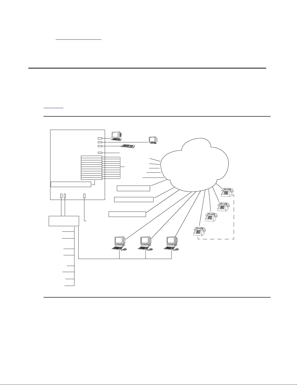
System Configuration Overview
The CS700/CS780 can be configured to conduct audio conferences using Public Switched
Telephone (PSTN) lines. Operator audio paths and links can be set up as conventional lines.
Figure 1
depicts various system components and features in a PSTN environment.
Figure 1: System Feature Configuration
Audioconference System
Console Port
Monitor Port
Keyboard Port
Analog Music Source
Revenue lines
Operator lines
Music (FDAPI)
Play/Record
Link lines
Digital Music Source
Analog Record/Playback
Linked Bridge
NICs/DSPs
Digital Record/Playback
LAN Ports
Ethernet
LAN Hub
Reserver
Enterprise
Billing
Web Conferencing
Server
PIN Code
Administration
External
Passcode Server
MultiSite
Web Portal
SNMPClient
RCA Jack
Modem Port
External
Modem
Operator
Data & Control
Operator
Audio
Network
Conferees
16 Administration and Maintenance of the S700/780 Audio Conferencing Server
Page 17

Audioconferencing Features
This section provides an overview of the system’s audioconference feature set. It also
introduces concepts and terminology used throughout the remainder of this manual.
Attended Conferences
An attended conference is a conference in which an operator, using the Bridge Talk application
for managing and scheduling conferences, places callers into the conference and remains
available to assist conferees and moderators throughout its duration. The CS700/CS780 can be
configured for support operators, who can manage and monitor conferences alone or as part of
a team. They can also record annunciator messages, create and edit dial lists, dial out to
conference participants, record and playback recorded conference dialog, run question and
answer and polling sessions, and print conference reports directly from their workstations.
Attended conferences are scheduled and configured with the Conference Scheduler
application. To join an attended conference, conferees either dial in at a designated time or an
operator dials out to conferees. When dialing out, an operator can either dial a phone number
directly from the keyboard or launch an automated dialing function that dials numbers from a list
stored on the system (blast dialing).
Audioconferencing Features
See the ACS Managing and Scheduling Conferences Guide for details on the Conference
Scheduler.
Unattended Conferences
An unattended conference is a conference in which conferees gain access to and participate in
a conference without operator assistance. (Operator assistance, however, can be provided as
necessary.) When callers dial in to the unattended conference they are prompted to provide one
or more security codes to enter the conference. Once the system validates the code(s), the
caller is routed directly to the conference, but the system can also be configured to route callers
to a waiting queue to receive operator assistance.
Like attended conferences, specific conference features are set up using the Conference
Scheduler application from Bridge Talk. For instance, Auto Blast, a feature that enables
moderators to initiate a blast dial or enables the system to initiate a blast dial when the
moderator enters a conference is a conference-specific feature. System-wide operational
parameters for unattended conferences are specified by the Conference Scheduler
Configuration set up by a system administrator. See Chapter 7:
Scheduler on page 173 for details on configuring the Conference Scheduler and other
unattended conference features.
Configuring Conference
Issue 1 November 2008 17
Page 18

System Features
Other features that can be configured for unattended conferences on a system-wide basis
include:
● Auto Extend Duration — The system attempts to extend a conference beyond its
scheduled end time.
● Auto Extend Ports — The system attempts to allocate additional ports to conference to
accommodate additional conferees.
● Early Start Minutes — Conferees can enter a conference 1 to 30 minutes earlier than the
scheduled start time if ports are available.
● External Passcode Validation — An external database validates the first access code
submitted for entry to a conference and then uploads conference parameters to the
system.
● PIN Mode — Specifies whether PIN code implementation is optional, whether non-unique
PIN codes are required (all conferees enter same PIN code), or whether unique PIN codes
are required (all conferee enter a different PIN code).
On-Demand Conferences
The system enables you to designate a percentage of system lines for On-Demand
conferences — ad hoc, unattended conferences that can be convened on a first-come,
first-served basis during a pre-scheduled time period. On-Demand conferences are configured
using the Conference Scheduler application. Schedulers can schedule one-time conferences or
a reoccurring conferences. An On-Demand conference can, for example, extend continuously
(24 hours a day, seven days a week), 9 AM to 5 PM Monday through Friday, 1 AM to 6 AM
every Saturday, 9 AM to 5 PM on 10th of each month, 12 AM to 12 PM on August 31, 2007, or
over any other span during which conferees want to insure lines are available for a conference
at a moment’s notice. See Meeting Exchange 5.1 Bridge Talk User’s Guide for details on
scheduling On-Demand conferences.
Like other unattended conferences, an On-Demand conference begins when the first conferee
calls in and provides a valid access code, and an On-Demand conference customer can
convene as many consecutive conferences as they want within the specified time period.
However, lines for On-Demand conferences are available on a first-come, first-served basis;
that is, successful convocation of On-Demand conferences is dependent on the availability of
lines for On-Demand conferences. See Configuring Conference Scheduler
on page 173 for
details on apportioning a percentage of system lines for On-demand conferences that will meet
your requirements.
18 Administration and Maintenance of the S700/780 Audio Conferencing Server
Page 19

Flex Conferences
Flex is a type of unattended, on-demand conference in which participants can join a conference
directly. This “reservationless” conference uses a profile to keep track of all the selected
conference features, such as Hang up or Name Record/Playback.
Audioconferencing Features
Once the system administrator has defined the settings in a profile, participants can join Flex
conferences on a first-come, first-served basis. However, there can be only one moderator
(leader). Leaders can change profile settings before a conference begins, and create, control,
and end a conference call using DTMF telephone commands. For example, moderators can:
● SPECIFY A CONFERENCE PASSWORD. Leaders can optionally add another layer of
security by specifying a passcode that participants must enter before they can join the
conference. This password is valid only for the duration of the conference and is not stored
on the system.
Note:
Note: If Music is turned on for the conference, participants who arrive early wait on
standby. If the moderator specifies a passcode upon arrival, the waiting
participants must enter the passcode before they are allowed into the conference.
However, if Music is turned off, participants who arrive before the moderator can
enter the conference without the passcode.
● CHANGE CONFERENCE OPTIONS. When a participant enters a leader PIN code and
assumes leader (moderator) status, the system immediately prompts the leader to press 1
to start the conference. However, the leader can press 2 to change several conference
options before the conference starts. After changing options, the leader can press 1 to
start the conference.
● USE SPECIAL STAR COMMANDS. Flex conferences require that leaders and participants
use special DTMF commands during the conference. A leader can create, control, and
end a conference call using keypad star commands, which toggle on and off.
For more information on the default call flow and Flex options, see Reservation Features on
page 129. For instructions on configuring bridge settings for Flex conferences, see Flex
Configuration Settings on page 76.
For more information on scheduling Flex conferences, refer to the ACS Managing and
Scheduling Conferences Guide.
Note:
Note: Flex does not support Polling or Q&A.
Conference Overbooking
The system’s overbooking feature enables you to specify the percentage of system lines you
want available for Conference Overbooking. Overbooking enables you to schedule more
Issue 1 November 2008 19
Page 20

System Features
conference lines than the system supports. In light of the fact that some conference participants
do not attend conferences as scheduled, this feature ensures that those scheduled yet unused
lines are immediately available for other conferences.
Refer to Chapter 7:
Configuring Conference Scheduler on page 173 for details on apportioning
a percentage of system lines for Conference Overbooking that will meet your requirements.
External Passcode Validation
External Passcode Validation (EPV) is an optional feature that enables the system to validate
conference security passcodes (conferee and moderator passcodes) for unattended
conferences from an external database (e.g., Oracle database) instead of from the system
database. Basically, the system submits to an external database the passcode entered by the
first caller (moderator or conferee) who attempts to enter a conference. Upon determining the
code is valid, the database provides the system the conference information required to convene
the conference and validate passcodes entered by subsequent callers.
See Using External Passcode Validation
Call Routing Service
The Call Routing Service provides automated processing of incoming calls based on either
DNIS or DDI digits. Services include:
on page 181 for details.
● Call branding — Lets you assign conference-specific greeting and instructional messages
to callers.
● Call routing — Lets you specify the method used to process a call.
Conference Record and Playback
The system supports two modes of conference record and playback:
● Digital Record/Playback (DRP) — DRP enables conference operators and moderators to
digitally record up to 12 hours of dialog per conference and play it back. Up to 1,000
simultaneous recordings and playbacks can be running on a system. 770 hours of digitally
recorded conference dialog can be stored on either the system’s removable hard drive or
the RAID system, depending on how the system is configured.
● Analog Record/Playback — Using FDAPI, the system can support up to 48 analog record/
playback channels. Conferences are recorded on and played back from an external
audio-recording device. The audio recording device is accessed over a dedicated phone
line that has been set up for that purpose in the FDAPI configuration (see
FDAPI on page 163).
Configuring the
20 Administration and Maintenance of the S700/780 Audio Conferencing Server
Page 21

● Off-Bridge Recording — This mode allows the system to connect to an external recording
device. The time limit is determined by the recording device.
See the ACS Managing and Scheduling Conferences Guide for details on recording and playing
back conference dialog.
Sub-Conferences
Sub-conferencing enables a group of participants to leave a main conference to discuss topics
of a confidential nature or that are unrelated to the topic of discussion in the main conference.
The CS700/CS780 can be configured to allow a conferee, a moderator, or both to convene a
sub-conference from a main conference. Both conferees and moderators, however, can join a
sub-conference regardless of which type of conference participant started the conference.
The system allows up to nine concurrent sub-conferences to be created from a main
conference, but it does not impose any limits on the number of successive sub-conferences that
can be created. The system does not permit creation of a sub-conference from another.
Audioconferencing Features
See System Configuration
on page 45 for details on enabling the sub-conference feature on the
system.
Although it inherits most of the configuration settings of the main conference from which it is
created, a sub-conference is essentially a distinct conference:
● A sub-conference can be secured (no one allowed entry into the conference) by a
moderator in the sub-conference. Whether or not a main conference is secured has no
effect on the sub-conference.
● Once a moderator secures a main conference, participants in a sub-conference may not
rejoin the main conference until the moderator unsecures it. When the participant attempts
to rejoin a secured main conference:
● the system plays the moderator a notification message such as, “Your conference is
currently secured. A participant of the Sub Conference is requesting re-entry. Please turn
off security to unlock the conference.”
● the participant hears a message such as, “The main conference has been secured and
entry is not allowed at this time. The moderator has been notified of your request, please
stand by...” Once the moderator removes the security, the system plays a message such
as, “Re-entry to the main conference is now allowed.
● A sub-conference’s roster is played independently of its main conference roster.
● The system generates a Conference Detail Record (CODR) for each sub-conference
”
created from a main conference. (A CODR is a daily report that contains data from all
conferences that occurred for the day. See
CODR Configuration, screen 1 on page 277 for
details.)
Important information about main and sub-conference CODRs:
Issue 1 November 2008 21
Page 22

System Features
● The values for the Cross Ref fields and the values for the Conference ID fields for main
and sub-conference CODRs are identical. This enables billing or auditing personnel to
correctly associate sub-conferences with main conferences.
● The User Conf Type field in a sub-conference CODR identifies the conference as a
sub-conference.
● Sub-conferences are recorded separately from the main conference.
The following system-wide conference features applicable to a main conference are not
applicable to a sub-conference:
● Auto-Extend-Ports — The system does not extend ports for a sub-conference. Ports
added to a main conference are also available for any new or existing sub-conference
created from the main conference. Any additional participants who wish to join a
sub-conference can enter the main conference and then transfer to the sub-conference.
● Auto-Extend-Duration — The system does not allow individual extension of a
sub-conference. The duration of an existing sub-conference extends as long as the main
conference duration extends.
How Participants Access and Exit a Sub-Conference
A conference participant (moderator or conferee) uses the keypad command, *93, to create and
transfer to and from a sub-conference:
● When a participant in a default call flow main conference presses *93 plus a digit 1- 9,
where the digit corresponds to the subconference, the system creates a sub-conference
or, if sub-conference has already been created, the system routes the participant to that
sub-conference.
● Participant lines are transferred to the sub-conference and thus subtracted from the main
conference. The Call Detail Record (CDR) the system generates for each line in a
conference indicates that the line was transferred.
● When a participant presses *930 while in the sub-conference, the system returns the
participant line to the main conference.
A sub-conference ends when all participants have left the sub-conference.
Tip:
Tip: For a Flex conference, one sub-conference only is supported. Press *93 to
access a Flex sub-conference.
Role of the Conference Moderator
A sub-conference “shares” the moderator(s) from the main conference. That is, no additional
moderators are required to manage a sub-conference; moderators can enter and exit a
sub-conference at will.
22 Administration and Maintenance of the S700/780 Audio Conferencing Server
Page 23

Audioconferencing Features
Questions and answers about the role of a moderator in a main conference and a
sub-conference:
● What happens when the only or last moderator in the main conference joins a
sub-conference and the system is configured to automatically end a conference (Auto
Hang-up feature enabled) when the last moderator in the conference disconnects?
● The system does not end the main conference. The feature is applicable only when the
last moderator leaves the main conference.
● What happens when the only or last moderator in the main conference disconnects from a
sub-conference and the system is configured to automatically end a conference (Auto
Hang-up feature) when the last moderator in the conference disconnects?
● The system ends both the main conference and the sub-conference.
● When a moderator secures a main conference (disallows entry to any additional
participants) is the sub-conference secured as well?
● No. A moderator can secure a sub-conference only while in the sub-conference.
● Can participants become stranded in a sub-conference (unable to transfer back to the
main conference) if the only moderator transfers from a secured main conference to
sub-conference?
● No. An annunciator message notifies the moderator to unsecure the main conference
before transferring to the sub-conference. The moderator cannot transfer to the
sub-conference until the main conference is unsecured.
● Can participants become stranded in a sub-conference (unable to transfer back to the
main conference) if the only moderator disconnects from a secured main conference and
the Auto Hang-up feature is not in effect (the conference continues as scheduled)?
This scenario is possible. If a conference requirement is that all participants must be able to
re-join a main conference before it ends, the moderator must ensure that all participants can
re-join the conference by not securing the conference prior to hanging up.
Conference Scheduler
The Conference Scheduler, which can be accessed from the Bridge Talk application, enables
you to schedule every type of conference supported by the system — attended, unattended,
and on-demand conferences. The system stores and automatically activates schedules.
Reservations that do not include an end date are considered to be valid for as long as the
system is active.
The Scheduler lets you specify conference setup information such as, but not limited to, start
time, end time, and number of lines. Also, the Scheduler notifies you if it detects scheduling
conflicts such as those related to the availability of lines or security codes, and it allows you to
modify the schedule as required. You can use the Scheduler to modify scheduled conference
settings at any time prior to a conference, and you can also modify the number of lines and the
duration of the conference and its security code while a conference is in progress. The
Issue 1 November 2008 23
Page 24

System Features
Scheduler also enables you to view and print scheduling reports and purge expired conference
information.
See the ACS Managing and Scheduling Conferences Guide for Conference Scheduler details.
Auto Blast
The optional Auto Blast feature provides blast-dial capability for moderators in unattended
conferences. From the Conference Scheduler application, Auto Blast can be disabled, set for
manual implementation, or set for automatic implementation.
● Manual implementation — The conference moderator enters *92 on the telephone keypad
to initiate the blast dial.
● Automatic implementation — The system initiates the blast dial when the first moderator
enters the conference via a moderator passcode.
The total number of blast dial recipients called from the blast dial list is dependent on the
maximum number of lines available for the conference. A system message announces to the
conference how many numbers from the dial list are dialed.
See Blast Dial Parameters
important details on setting the CLPG (call in progress) timeout period for Auto Blast used in
unattended conferences.
on page 69 for information about blast dial settings, including
Saved Roster Recordings
The system can be configured to generate and save an audio recording of information provided
by conference participants (name, affiliation, and so on). For conferences that include the roster
recording feature, participants provide the information in response to an audio prompt when
they attempt to enter a conference.
A raw audio file is created and saved on the system as soon as a participant records his name.
Each time a participant records his name, the information is appended to the raw audio file—so
the file grows as conference participation grows. The audio files are saved in pcm format.
See System Configuration
Roster Audio Files on page 210 for more information on roster recording files.
on page 45 for details on enabling roster recordings. See Saved
SNMPv2 Management Support
The system’s SNMPv2 management agent provides the interface between the system MIB and
SNMP-compliant network management applications that connect to the system to monitor
system, runtime, telecom trunk, and LAN resources. Comprising a combination of select MIB-II
24 Administration and Maintenance of the S700/780 Audio Conferencing Server
Page 25

Conference Call Modes
objects and platform-specific object, the MIB provides remote monitoring support for crucial
system components.
Unsolicited data from SNMP trap objects notify network management stations of actual and
potential problems with system, processor, memory, and network components (see System
Component Alerts on page 25. Current, average, and accumulated data from the MIB’s
read-only objects derived and monitored by management applications can be used by system
and network administrators to evaluate system performance. Most importantly, both unsolicited
and solicited data from the MIB can serve as input for automated alarm notification or
trouble-ticket applications used in conjunction with or part of the network management platform.
See SNMP Agent Configuration and MIB Object Definitions
guidelines and a list of MIB object definitions.
Contact Customer Support for assistance with enabling and configuring SNMP support on your
system.
System Component Alerts
The system MIB’s trap objects alert network managers about potential and actual problems with
system elements and processes:
● Core system resources — Fan, temperature, power supply.
● Runtime resources — Disk space (90% threshold), memory (75% threshold), host and
DSP processor, NICs.
● Telco resources — Signaling and frames.
● LAN resources — Link down and transmit and receive errors.
on page 333 for agent configuration
Conference Call Modes
A call mode is the method by which a conferee gains access to a conference. The system
supports several call modes to accommodate various customer requirements. A conference
can be conducted several ways. The system accommodates attended and unattended
conferences simultaneously, and even allows semi-attended calls, depending upon system
configuration.
In an attended conference, the operator greets the participant and places them directly into a
conference. No passcode is required. In an unattended conference the participant enters a
passcode to be placed directly into a conference. No operator is required. Operators can
manage participants in both attended and unattended conferences.
For example, if you have an operator, you can arrange unattended coded conferences, which
allow conferees, who forget their conference passcodes, to reach an operator, rather than being
Issue 1 November 2008 25
Page 26

System Features
automatically disconnected. In addition, you can run a conference that is unattended except for
an operator initiated blast dial.
The system also permits combinations of certain modes. For example, the moderator of an
attended dial-in conference can ask an operator to dial out to a conferee who has not dialed in.
How a Conferee Is Placed in a Conference
Conferees gain access to conferences in eight different ways.
● Five ways involve dial-outs from the system to the conferee.
● Three ways involve dial-ins from conferees to the system.
Dialing Out to Conferees
There are different ways for operators and moderators to dial out to a participant:
Operator Dial Out
● Immediate — An operator manually dials a phone number directly from the keyboard.
● Fastdial — An operator dials participants from a list stored on the system.
● Blast Direct — An operator has the system simultaneously dial an entire list of numbers.
Conferees are automatically placed in the conference after they answer the call and enter
a “1.”
● Blast Direct to Conference—An operator invokes the system’s blast dial feature to
simultaneously dial an entire list of numbers. The system places answered lines directly
into a conference.
● Blast Coded — An operator invokes the system’s blast dial feature to simultaneously dial
an entire list of numbers. The system prompts conferees for a conference passcode,
before the system places them in the conference.
Moderator Dial Out
● Originator Dial Out (ODO) — A moderator dials out to a conferee during the conference.
● Automatic Blast—As soon as the moderator joins the conference, the system dials a pre-
configured blast list.
● Manual Blast—A moderator initiates dialout to a preconfigured list using DTMF
commands.
Conferee Dial In
The system provides three methods of processing conferee calls to the system:
26 Administration and Maintenance of the S700/780 Audio Conferencing Server
Page 27

Hardware Features
● Direct — The system automatically routes incoming callers directly to a specified
conference. No access code is required.
● Coded (Unattended) — The system requests that a caller enter a pre-specified access
code to enter the conference. The system automatically routes the caller to the specified
conference. An additional security layer is available by using PIN codes.
● Attended — Operator places callers into the conference.
While not all calls require an operator to respond to incoming calls, there is often the need to
have one or more operators available to initiate and/or process calls, and to be available to help
moderators or conferees needing assistance.
Table 1
.
summarizes the operator involvement in the various conference call modes.
Table 1: Operator Involvement in Various Conference Call Modes
Conference
Call Mode
Operator
Initiated?
Operator
Processed?
Operator
Attended?
Code
Required?
Direct No No No No
Coded No No No Yes
Dial In
Attended No Yes Yes No
Immediate Ye s Yes Ye s No
Fastdial Yes Yes Yes No
Blast Direct Yes No Yes No
Blast Coded Yes No Yes Yes
Dial Out
Hardware Features
The foundation of the CS700/CS780 is the scalable, modular chassis, which can be rack
mounted or simply placed on a suitably sturdy structure. (See Site Requirements
for details.) It accommodates all hardware, software, and environmental components necessary
to support the system’s audioconferencing features and basic data storage requirements.
CS700/CS780 Conferencing Server hardware components:
● Telecommunication Network Interface Cards (NICs), each with eight RJ-45 ports that
support scalable T1, T1-ISDN, or E1 channel configurations.
● The CS700 supports up to six NICs (1152 T1, 1104 T1-ISDN PRI, and 1200 E1
channels).
on page 319
Issue 1 November 2008 27
Page 28

System Features
● The CS780 supports up to 3 NICs (576 TI, 552 T1-ISDN PRI, and 600 E1 channels).
● Up to three (3) hot-swappable Digital Signal Processing (DSP) cards in the CS780, and six
(6) in the CS700. DSP cards process audioconference operations. Use these equations to
calculate the number of DSP resources:
● T1 systems require T1 = 1 DSP board.
● T3 systems require T3 = 3n DSP +1, where n is the number of T3 cards.
28 Administration and Maintenance of the S700/780 Audio Conferencing Server
Page 29

Hardware Features
● CPU host processor card with a minimum processing power and RAM to support the
installed system features.
Tab le 2 identifies the supported T1/E1 that are required for
various system features and Table 3 the supported T3 system configurations.
.
Table 2: Supported T1/E1 Configurations
CS CPU MHz MEM
Meg
Max #
Ports
700 5550 700 512 1152
700 5550 700 512 1152
700 5550 700 512 1152
780 5550 700 512 576
780 5550 700 512 576
700 5551 1000 1024 1152
700 5551 1000 1024 1152
700 5551 1000 1024 1152
700 5551 1000 1024 2016
700 5551 1000 1024 2016
700 5551 1000 1024 2016
700 5551 1000 1024 2016
780 5551 1000 1024 576
780 5551 1000 1024 576
780 5551 1000 1024 576
NRP Calls/
Call Flow
second
1
5 cps,
5 Flex
15 sec rec
1
1
2
2
1
NO 6 Flex
NO 8 Default
NO 8 Default
NO 6 Flex
5 cps,
5 Flex
15 sec rec
1
1
3
NO 6 Flex
NO 8 Default
5 cps,
5 Default
15 sec rec
3
5 cps,
5 Flex
15 sec rec
3
3
2
NO 6 Flex
NO 8 Default
5 cps,
5 Default
15 sec rec
2
2
NO 8 Default
NO 6 Flext
1. 1200 ports for an E1 configuration.
2. <=600 ports for E1 configuration.
3. 1932 ports for T3 ISDN configuration.
The CPU card can be configured to include a hard drive and 3.5” disk drive if a RAID
system is not used. It also includes two DB9 serial ports, a keyboard /mouse port, a SVGA
port, a USB port, and two RJ-45 LAN ports that are each configurable for 10 or 100 Mbps
Ethernet connections.
Issue 1 November 2008 29
Page 30

System Features
.
Table 3: Supported T3 Configurations
Mixed Configuration
Total
System CPU
T1 T3 ISDN T3 CAS
Ports
CS700 5551 0 1932 0 1932
CS700 5551 0 1932 0 1932
CS700 5551 0 1932 0 1932
CS700 5551 0 1932 0 1932
CS700 5551 0 644 1344 1988
CS700 5551 0 1288 672 1960
CS700 5551 0 0 2016 2016
CS700 5551 768 0 672 1440
CS700 5551 768 644 0 1412
CS700 5551 384 0 1344 1728
CS700 5551 384 1288 0 1672
CS700 5551 0 0 2016 2016
CS780 5551 0 0 672 672
CS780 5551 0 644 0 644
● Redundant, hot-swappable power supplies: up to four for the CS700; up to two for the
CS780.
● RCA Jack (on a DSP card) for connection to analog music source (CD player for
example).
● Removable hard drive (for storing digitally recorded conferences and system file backups).
Note:
Note: Your system might be configured with a RAID drive instead of a removable hard
drive. See
RAID System on page 39 for more information.
Standard System Components
Figure 2 shows CS700 components for a non-RAID configuration and Figure 3 shows CS780
components for a non-RAID drive configuration. See RAID System
on a RAID configurations.
on page 39 for information
30 Administration and Maintenance of the S700/780 Audio Conferencing Server
Page 31

Hardware Features
Note:
Note: The system has video and keyboard connections on the host CPU and on the
optional embedded CPU (eCPU). These connections are used only for initial
startup of the system during installation and for local system diagnostics and
troubleshooting. The serial and ethernet ports on the NIC card and the serial port
on the DSP card are only used by the CS700/CS780 developers for application
development.
Serial ports are available on the front and the back of the system, but only one of the two ports
can be functional. If the front port is in use, the rear port is disabled, and if the rear port is used,
the front port is disabled. LAN ports are available on the front and the back of the system. When
the front port is in use, the rear port is disabled, and if the rear port is used, the front port is
disabled.
Issue 1 November 2008 31
Page 32

System Features
Figure 2: CS700 Components (RAID configuration differs.)
)
1
Front
4
5
6
7
8
10
11
12
13
14
15
9
17
18
19
16
20
2
3
22
21
Rear
23
24
26
25
1
27
19
28
29
30
15
31
13
12
8
9
Figure notes:
1. ESD Jack 12. CD-ROM Drive 22. Hard Drive (removable)
2. DSP Card 13. DSP Monitor Port 23. RCA Jack
3. CPU Card (ZT5551) 14. Ethernet B Port
(secondary)
24. Ethernet A Port
(primary)
4. USB Port 15. VGA Monitor Port 25. Alarm Cutoff Button
5. Reset Button 16. Com 1 Port 26. Keyboard Port
6. 3.5” Disk Drive 17. Network Interface Card 27. 10 Base T LAN Port
7. NIC Monitor Port 18. Fan Bay 28. Power Supply
8. AC Receptacle 19. Circuit Breaker (Power
29. Ground
Switch)
9. Network Port 20. Network Adaptor
Transition Card
10. Dry Relay Contact
21. Console Port 31. Modem Port
30. Processor Transition
Card
Connector
11. Mouse Port
32 Administration and Maintenance of the S700/780 Audio Conferencing Server
Page 33

Figure 3: CS780 Components (RAID configuration differs.)
Hardware Features
Front
1
6
7
15
16
12
17
18
19
20
2
3
13
4
5
8
10
14
9
11
Rear
22
13
14
21
23
25
24
9
Figure notes:
1. Power Supply 2. DSP Card 3. DSP Monitor Port
4. USB Port 5. RCA Jack 6. 10 Base T LAN Port
7. NIC Monitor Port 8. Alarm Cutoff Button 9. Reset Button
10. Com 1 Port 11. Keyboard Port 12. CPU Card (ZT5551)
13. Ethernet B Port
(secondary)
14. Ethernet A Port
(primary)
15. VGA Monitor Port
27
26
28
29
16. 3.5” Disk Drive 17. ESD Jack 18. CD-ROM Drive
19. Hard Drive
(removable)
20. Fan Bay 21. Processor Transition
Card
22. Console Port 23. Modem Port 24. Keyboard Port
25. Mouse Port 26. Network Port 27. Network Adaptor
Transition Card
28. Power Switch 29. AC Receptacle
Note:
Note: Figure does not show optional components such as rack mounting brackets and
the protective cover.
Issue 1 November 2008 33
Page 34

System Features
Network/DSP Card Configurations
This section describes network and DSP card pairing requirements and the numbering scheme
for network and DSP cards in the system chassis.
NIC/DSP Card Combinations
The CS780 chassis holds up to three NIC/DSP pairs, and the CS700 holds up to six NIC/DSP
pairs. The DSP system dynamically allocates DSP processing bandwidth so that all channels in
the same conference are processed on the same DSP node. The system can also process
large conferences by internally linking DSP nodes.
The CS700/CS780 Conferencing Server can include various network interface card
configurations. Table 4
pairings.
Table 4: Possible NIC/DSP1 Configurations
Number of Ports Number of NICs Number of DSPs
T1: 24 - 192
T1 (ISDN PRI): 23 - 184
E1: 30 - 180
summarizes possible port configurations and NIC and DSP card
1 1
T1: 240 - 384
T1 (ISDN PRI): 230 - 368
E1: 270 - 390
CS780
T1: 480 - 576
T1 (ISDN PRI): 430 - 736
E1: 510 - 600
2 2
3 3
1 of 2
34 Administration and Maintenance of the S700/780 Audio Conferencing Server
Page 35

Table 4: Possible NIC/DSP1 Configurations (continued)
Number of Ports Number of NICs Number of DSPs
T1: 192
T1 (ISDN PRI): 184
1 1
E1: 180
T1: 384
T1 (ISDN PRI): 368
2 2
E1: 390
T1: 576
T1 (ISDN PRI): 552
3 3
E1: 600
T1: 768
CS700
T1 (ISDN PRI): 736
4 4
E1: 780
T1: 960
T1 (ISDN PRI): 920
5 5
E1: 990
Hardware Features
T1: 1152
T1 (ISDN PRI): 1104
E1: 1200
6 (for T1 & ISDN
PRI)
6
5 (for E1)
2 of 2
1. NS300 and NS301
Note:
Note: The actual number of installed channels available for conferees is the difference
between the number of channels on the system and those used by the Flexible
Digital Auxiliary Port Interface (FDAPI) for other conference requirements and
functions. See
Configuring the FDAPI on page 163 for information on FDAPI
channels.
NICs can be configured on a trunk-by-trunk basis to support various combinations of the
following signaling protocols:
● E1 ISDN
● T1 in-band E&M
● T1 NA-ISDN PRI
Issue 1 November 2008 35
Page 36

System Features
Card Numbering
Log files and network statistic reports reference network and DSP cards by number. The system
assigns numbers to cards based on their relative positions in the chassis and not according to
the slots they occupy in the chassis. Also, DSP cards and network cards each have a separate
numbering series. When the optional embedded CPU (eCPU) is installed on the system, it is
located in the first slot.
Figure 4
illustrates the card numbering scheme.
Figure 4: Network and DSP Card Numbering
123456
e
C
P
U
CS700
CPU
Front View
NICs NICsDSPs
654321
e
123123CPU
C
P
U
Front View
DSPs
CS780
Input/Output Ports
Table 5 lists and describes system ports. I/O ports may either be located on the back, front, or
both locations.
Table 5: I/O Port Descriptions
Port Location Description Purpose
COM 1
(Console)
Front and
Back
RS232 serial port, 9-pin
micro “D” female
“Dumb serial terminal”
connection.
COM 2
(Modem)
Keyboard Back Mini DIN, standard
Back RS232 serial port, 9-pin
micro “D” female
PS-2 pinout
Modem connection.
Keyboard connection. The
port on either the CPU card
or Processor Transition
card can be used, but not
simultaneously.
Mouse Back Mini DIN, standard
Mouse connection.
PS-2 pinout
Keyboard and
Mouse
36 Administration and Maintenance of the S700/780 Audio Conferencing Server
Front Y-cable Keyboard and mouse
connection.
1 of 3
Page 37

Table 5: I/O Port Descriptions (continued)
Port Location Description Purpose
Hardware Features
Video Front SVGA Graphics, 15-pin
mini “D”, standard VGA
pinout
USB 1 in Front
4-pin USB connector Reserved for future
1 in Back
LAN A
(Ethernet)
CS780 Front
CS700 Back
8-pin modular jack Primary 10baseT/
Note:
May be
changed in
BIOS
LAN B
(Ethernet)
CS780 Front
CS700 Back
8-pin modular jack Backup 10base T/
Note:
May be
changed in
BIOS
Monitor connection.
implementation.
100baseT LAN port.
On the CS700 only the rear
port is enabled during
manufacturing. However,
this configuration can be
reversed by an authorized
service technician.
Both front and rear ports
cannot be used
simultaneously.
100baseT LAN port. This
port can be configured by
an authorized technician as
the primary LAN port in the
event of LAN A port
malfunction.
On the CS700 the rear port
is enabled during
manufacturing and the front
port is disabled. However,
this configuration can be
reversed by an authorized
technician.
Both front and rear ports
cannot be used
simultaneously.
DSP Mon Front 8-pin modular jack DSP card monitoring
connection.
NIC Mon Front 8-pin modular jack NIC monitoring connection.
NIC LAN Front 8-pin modular jack Reserved for future
implementation.
2 of 3
Issue 1 November 2008 37
Page 38

System Features
Table 5: I/O Port Descriptions (continued)
Port Location Description Purpose
Network Back 8-pin modular jack Local or public telephone
Audio Device Front RCA jack Supports an external music
Media Drives
Table 6 lists and describes system media drives (standard configuration).
Table 6: Media Drive Descriptions
Drive Purpose
CD-ROM drive For installing system software.
network switch connection.
source.
3 of 3
Internal hard drive
(The internal drive is not available if the
system includes a RAID system.)
Removable hard drive (Optional)
(The optional removable hard drive is not
available if the system includes a RAID
system.)
RAID System (Optional)
(See RAID System on page 39.)
Power Supply
The CS700 can be configured with up to four power supply modules, which can provide up to
600 watts of output. The CS780 can be configured with either one or two power supply
modules, which can provide up to 600 watts of output. Power supplies for both system models
are hot swappable.
See Site Requirements
For storing system data.
For storing digitally recorded
conferences and saved rosters. The
drive can also be used to back up
system files from the internal hard
drive (see
Restore Menu on page 208).
For storing system data.
on page 319 for information on power requirements.
Working with the Backup/
38 Administration and Maintenance of the S700/780 Audio Conferencing Server
Page 39

RAID System
The optional RAID System configuration replaces the system’s standard on-board hard drive
and the optional removable hard drive. Figure 5
of the system.
Figure 5: RAID Components on front of system
Hardware Features
shows RAID components located on the front
1
9
2
7
8
Figure notes:
1. Faceplate latch
2. Powerswitch
3. Green LED when the system power is on.
4. Red LED when the power supply fails. The system will also sound a beep.
5. Red LED when the temperature exceeds its setting
6. Red when the cooling fan fails
7. Green LED when the drive is online.
8. Red if the hard drive fails.
9. Disk drive carriers capable of hot swap.
Figure 6 shows RAID components located on the back of the system.
Figure 6: RAID Components on back of system
1 2 3 4
3
.
4
5
6
Figure notes:
1. Reset button for buzzer
2. Backplane B SCSI-3 Cable Connector
3. Backplane A SCSI-3 Cable Connector
4. Greed LED when power supply is on.
5. Attach/Detach Lever
6. Power Supply capable of hot swap.
7. Power Supply On/Off switch
8. Power Cord connector
9. Cooling Fan
56789
Issue 1 November 2008 39
Page 40

System Features
Figure 7 shows RAID components located on the CPU Card.
Figure 7: RAID Components on CPU Card
Figure notes:
1. RAID Controller Module
2. IOP LED
3. SCSI-3 Cable Connector
The system supports four drives configured as a single physical array and one standby drive in
either or each of the drive enclosure’s two backplane segments. Each drive provides 18 GB of
storage size. The physical array is configured as three separate logical drives — one 8 GB drive
for the root directory, one 8 GB drive for the /usr3 directory, and one 35 GB drive, which is
unused. The maximum physical array size is approximately 51 GB.
1
2
3
A single RAID system can be configured to support one CS700/CS780 on one of the system’s
backplane segments or two CS700/CS780s on each of the system’s two backplane segments.
● Figure 8 shows a RAID system supporting a single CS700/CS780.
● Figure 9 shows a RAID system supporting two CS700/CS780s.
40 Administration and Maintenance of the S700/780 Audio Conferencing Server
Page 41

Figure 8: CS700/CS780 Single System RAID Configuration
CS700 Configuration
Backplane Segment A Backplane Segment B
Hardware Features
12345
Redundant Disk Array Hot Standby
SCSI-3 Cable Connection
6 789101112
Floppy Disk
Drive
Unused
RAID Controller
Module Interface
CS780 Configuration
Backplane Segment A Backplane Segment B
12345
Redundant Disk Array Hot Standby
SCSI-3 Cable Connection
6 7 8 9 10 11 12
RAID Controller
Module Interface
Unused
Floppy Disk
Drive
Issue 1 November 2008 41
Page 42

System Features
Figure 9: CS700/CS780 Dual System RAID Configuration
Backplane Segment A Backplane Segment B
12345
Redundant Disk Array Hot Standby
Floppy Disk
Drive
SCSI-3 Cable Connection
RAID Controller
Module Interface
6 7 8 9 10 11 12
Redundant Disk Array Hot Standby
Floppy Disk
Drive
RAID Controller
Module Interface
SCSI-3 Cable Connection
Contact Customer Support for information on RAID system installation and configuration
options.
!
CAUTION:
CAUTION: When powering up the system, the RAID drive must be powered up either before
the bridge or at the same time. The bridge will not operate and serious damage
could result if the bridge is powered up with the RAID enclosure off.
Status LEDs
Figure 10 and Figure 11 show and describe system CPUs, NIC interface, DSP, and power
supply LEDs.
42 Administration and Maintenance of the S700/780 Audio Conferencing Server
Page 43

Figure 10: LEDs
NIC
RUN FAIL
AB
CD
EF
GH
PORTS
ACT LINK
ETHERNET
DIAG
ACT LINK
ETHERNET
RUN FAIL
AB
CD
EF
GH
PORTS
NIC LEDs Status Indications
RUN (Card)
FAIL (Card)
A - H On = Alarm
ACT On = Activity
LINK On = Link established
On = OK
On = Processor Failure
Off = OK
RUNFAIL
DSP LEDs Status Indications
RUN On = OK
FAIL On = Failure
HOT SWAP On = OK to Hot Swap
Off = Not OK to Hot
Swap
HOT SWAP
Hardware Features
DSP
RUNFAIL
HOT SWAP
Power Supply
STATUS
STATUS
Power Supply LEDs Status Indications
STATUS (CS780)
INPUT (CS700)
FAIL (CS700)
Green = OK
On = OK
On = Failure
Power Supply
INPUTFAULT
(CS700)
INPUT
FAULT
Figure notes:
1. The CPU’s yellow Major Alarm LED flashes once every 10 seconds to notify you that the
alarm system is correctly functioning.
Issue 1 November 2008 43
Page 44

System Features
Figure 11: 5550 and 5551 CPU LEDs
Peripherals
A CS700/CS780 installation typically includes the following peripheral devices:
E
N
E
T
B
A
E
N
E
T
A
U
S
B
V
G
A
MIN MAJ CRIT
RUN
SM
IDE
USR
1
C
O
M
1
K
E
Y
HOT SWAP
B
Indicators:
red = 100 Mbit/s
green = 10 Mbit/s
Ethernet
MIN Minor Alarm
MAJ Major Alarm
CRIT Critical Alarm
RUN Green = OK
CPU LED Status Indications
MIN MAJ CRIT
ACO
TAKE
PWR
USR
2
RUN
ACO
SM TAKE
IDE
USR
1
PWR
USR
2
ACO Alarm cut-off (CS700 only)
SM Not Implemented
TAKE Not Implemented
IDE Flash = Hard Drive Activity
PWR Green = Power On
Red = Fail
Indicates that the alarm was
manually silenced.
Red = Power Fault
USR1 Not Implemented
USR2 Not Implemented
Hot Swap LED
● UPS — To protect against data loss and prevent spontaneous system shutdown, Avaya
recommends the use of an Uninterruptible Power Supply (UPS) that provides 350 W or
more.
● External Maintenance Modem — Provides access to the system software interface.
● Console — Provides access to the system software interface.
44 Administration and Maintenance of the S700/780 Audio Conferencing Server
Page 45

Chapter 2: Configuring System-Wide Settings
Describes how to configure various system-wide conference settings, how to configure
annunciator delay, dial delay, disconnect notification, wink timeout, and line fault settings, how
to set the system date and time, how to configure blast dial settings, and how to assign voice
messages and tones to conference events.
Introduction
System-wide settings specify most of the common operational attributes for conferences.
This chapter is organized as follows:
● System Configuration on page 45 describes how to configure various system-wide
conference settings available from the System Configuration screen.
● Table 7: System Configuration Parameters on page 47 describes how to configure
parameters for annunciator delay, dial delay, line disconnect mode, and disconnect
notification mode settings available from the System Supervision screen.
● System Date and Time on page 68 describes how to set the system date and time.
● Blast Dial Parameters on page 69 describes how to configure blast dial-out parameters.
● Voice Message Configuration on page 71 describes how to configure the system to play
voice messages, tones, or both in response to conference events.
● Flex Configuration Settings on page 76 describes how to configure system-wide
conference settings to implement Flex Conferencing.
System Configuration
To display or configure general system settings:
1. Select System Administrator Main > Configurations > System Configuration to display
the System Configuration
dialog.
Issue 1 November 2008 45
Page 46

Configuring System-Wide Settings
Figure 12: System Configuration
Note:
Note: If the PIN Code feature is installed on the system, then the System Configuration
screen will include a PIN Mode field in the below the Time Format field; when it is
not installed, this space will be blank.
2. Page Down to see page 2 of System Configuration.
Figure 13: System Configuration Page 2
46 Administration and Maintenance of the S700/780 Audio Conferencing Server
Page 47

System Configuration
3. Configure parameter values as desired. See Table 7 for parameter descriptions.
4. Save (or cancel) your changes.
Table 7: System Configuration Parameters
Parameter Description
System Name Displays the TCP/IP host name assigned to the system when
system software is installed. The name appears on screens and in
various system files and serves as the alias for the system IP
address.
Entry Tone Specifies the number of beeps in an entry tone when a participant
enters a conference. Entry tones are specified for conferences on a
per-conference basis. Operators can enable entry tones in an
attended conference, and entry tones can be specified for
scheduled conferences.
● Single Beep (default)
● Double Beep
Refer to BridgeTalk documentation for details on enabling entry
tones for conferences.
Exit Tone Specifies the number of beeps in an exit tone when a participant
exits a conference. Exit tones are specified for conferences on a
per-conference basis. Operators can enable exit tones in an
attended conference, and exit tones can be specified for scheduled
conferences.
● Single Beep (default)
● Double Beep
DTMF
Acknowledge
Specifies whether or not systems sounds a tone when it receives
DTMF (Dual-Tone Multi-Frequency) dialing input.
● ON — The system emits a tone when conferees press valid
DTMF digits on their telephones to either enter a response to
a poll question or to place themselves in either the Help or
Q&A queues. Acknowledgment tones assure conferees that
the system received their DTMF input.
● OFF (default) — Conferees hear normal DTMF tones as they
press digits, but do not hear the special acknowledgment
tone afterward.
1 of 16
Issue 1 November 2008 47
Page 48

Configuring System-Wide Settings
Table 7: System Configuration Parameters (continued)
Parameter Description
Digit Recognition Specifies the number of telephone keys conferees must press to
use certain conference features.
● ONE (default) — The system requires conferees to press one
digit for these features.
● TWO (recommended) — The system requires that conferees
press two digits. Two-digit input reduces the possibility that a
frequency in the DTMF range occurs and causes the system
to respond as though a conferee pressed a DTMF digit.
Tip:
Tip: If you change this setting from ONE to TWO,
conferees must press *0 to ask for help, and
moderators must press *7 to turn on security.
Because lines are muted during Polling, two-digit
recognition does not apply.
For more information on accessing conference features using
telephone keys, see the BridgeTalk User’s Guide.
Q&A Digit
Recognition
Specifies the number of telephone keys conferees must press to
enter the Question queue during a Q&A period.
● ONE (default, recommended) — The system requires
conferees to press one digit to enter the Question queue.
● TWO — The system requires that conferees press two digits
to enter the Question queue. Two-digit input reduces the
possibility that a frequency in the DTMF range occurs and
causes the system to respond as though a conferee pressed
a DTMF digit. If you set this field to TWO, conferees must
press *1 to enter the Question queue.
Transaction Logs Specifies whether or not the system generates Operator
Transaction logs.
ON (recommended) — The system generates transaction logs.
OFF (default) — The system does not generate transaction logs.
See Operator Transaction Logs on page 220 for more information.
2 of 16
48 Administration and Maintenance of the S700/780 Audio Conferencing Server
Page 49

Table 7: System Configuration Parameters (continued)
Parameter Description
System Configuration
Automatic CDR
Print
Automatic Conf.
Clear
Specifies whether the automatic call detail record (CDR) and
conference detail record (CODR) exporting feature is enabled. This
feature can be configured to process (for example, print) records in
real-time: See
● LAN — The system exports CDRs across the LAN to a client
Real-time CDRs and CODRs on page 296.
in real-time. You must re-initialize the system after setting this
value to put it into effect (see
System Re-Initialization on
page 169).
● OFF (default) — The system does not automatically generate
real-time CDRs and CODRs.
Specifies whether the system automatically clears attended
conference settings when a conference ends. The system
generates a CODR and a Conference Report for a conference only
after that conference has been cleared.
● ON — The system automatically clears conference settings
when the last participant exits an attended conference.
Settings cleared include: Entry Tone, Exit Tone, Gain, ID,
Lecture, Links, Lock, Music, Name, Note, Playback, Record,
Security, and Time information.
● OFF (default) — An operator must run the Conference
Clear_all command in
BridgeTalk to remove features from
completed attended conferences.
See the BridgeTalk User’s Guide for details.
Note:
Note: The system automatically clears unattended
conferences regardless of this setting.
Attended ODO Defines whether or not moderators are able to use their telephones
to access an open line to dial out to add participants to an active
conference. This is useful for contacting conferees who cannot dial
in.
● ON — An attended-conference moderator can use Originator
Dial Out (ODO), if there is a free channel configured for ODO
Allow. See
Call Routing Configuration on page 84 for
information on enabling the ODO Allow parameter.
● OFF (default) — An attended-conference moderator cannot
use ODO.
The system restricts ODO to one moderator at a time per
conference.
3 of 16
Issue 1 November 2008 49
Page 50

Configuring System-Wide Settings
Table 7: System Configuration Parameters (continued)
Parameter Description
First Person
Message
Auto Extend
Duration
Specifies whether the system plays message 221; “You are the first
participant in this conference”, when the first conferee enters a
conference.
● ON — The message is played.
● OFF — The message is not played.
Specifies whether the system attempts to automatically extend the
duration of in-progress unattended conferences for 25 additional
minutes.
● OnDefault — The system attempts to extend unattended
conferences. Successful extension is dependent on the
availability of (non-reserved) lines and security codes. This
setting can be changed in the Conference Scheduler on a
per-conference basis.
● OffDefault — The system does not attempt to automatically
extend unattended conferences. This setting can be changed
in the Conference Scheduler on a per-conference basis.
● OFF (default) — The system does not attempt to
automatically extend unattended conferences. This setting
cannot be changed in the Conference Scheduler.
The system attempts to extend a conference three additional times
after successfully extending it the first time. This means that a
conference can extend up to 100 minutes beyond its original end
time. If warning tones are enabled, each time the system plays a
warning tone, it also attempts to extend the conference, including
one last time just before the conference ends. When warning tones
are not enabled for unattended conferences, the system attempts to
extend a conference one time just before a conference’s end time.
The system plays annunciator message 241 to inform a conference
that it has been extended; otherwise, the conference ends at the
scheduled end time.
Note: Auto Extend Duration is disabled, regardless of this setting, if
the External Passcode Validation (EPV) feature is enabled for the
system. See
Using External Passcode Validation on page 181 for
more information on EPV.
50 Administration and Maintenance of the S700/780 Audio Conferencing Server
4 of 16
Page 51

System Configuration
Table 7: System Configuration Parameters (continued)
Parameter Description
Auto Extend Ports Specifies whether the system is able to allocate additional conferee
ports (lines) to unattended conferences while they are in progress.
● OnDefault — The system attempts to allocate additional ports
to accommodate additional conferees as required.
Successful allocation of ports depends on the availability of
(non-reserved) ports. This setting can be changed in the
Conference Scheduler on a per-conference basis.
● OffDefault — The system does not attempt to allocate
additional ports. You can change this setting in the
Conference Scheduler on a per-conference basis.
● OFF (default) — The system does not attempt to allocate
additional ports. This setting cannot be changed in the
Conference Scheduler.
Note: Auto Extend Ports is not supported for Flex Conferences.
5 of 16
Issue 1 November 2008 51
Page 52

Configuring System-Wide Settings
Table 7: System Configuration Parameters (continued)
Parameter Description
Early Start Minutes Specifies whether conferees are allowed to enter unattended
conferences earlier (1 - 30 minutes) than the scheduled start time if
ports are available.
● OFF (default)— Conferees cannot enter conferences earlier
than the scheduled start time.
● 1 - 10, 15, 20, 25, 30 (minutes) — Conferees can enter
conferences earlier than the scheduled start time. The setting
specifies how early conferees can enter conferences.
!
WARNING:
WARNING: Two or more conferences may have conflicting
security codes when Early Start Minutes are either
turned on or extended. As a result, BridgeTalk users
will not be able to save or edit a reservation until
they change the start or end times so that the
security codes are no longer in conflict.
Administrators can use the procedure for
Identifying
conflicting reservations to help resolve this problem.
Identifying conflicting reservations
1. Log onto the system.
2. Run Informix DBACCESS.
Execute the p_ValAllRsrvtn() stored procedure using this
command:
EXECUTE PROCEDURE
‘bridgedbo’.p_ValAllRsrvtns()”
3. Query the MessageLog table to find all overlapping security
codes by using this command:
Select * FROM ‘bridgedbo’.MessageLog WHERE
MsgSrc = “p_ValAllRsrvtns”
Refer to the Relational Database Guide for additional information on
using DBACCESS and Stored Procedures.
6 of 16
52 Administration and Maintenance of the S700/780 Audio Conferencing Server
Page 53

Table 7: System Configuration Parameters (continued)
Parameter Description
System Configuration
Ignore DTMF
Commands
Operator
Assistance
Determines whether the system ignores DTMF commands entered
by conference participants.
● ON— The bridge ignores DTMF commands entered by
conference participants, and will override any of the individual
Conferee Mute and Conferee Gain settings. Help requests
are also blocked when this feature is active.
● OFF (default)—DTMF commands entered by conference
participants are interpreted by the bridge.
!
Important:
Important: This setting does not apply to Flex conferences.
Specifies whether operators provide help to entire conferences or
only to the conferee who requests help.
● INDVL (default)— The operator helps only individual
conferees who request help. The conferees are temporarily
removed from the conference to speak privately with the
operator.
● CONF — The operator provides help to the entire
conference. No one is removed from the conference during
help, and all conferees hear whatever assistance is provided
by the operator.
Note: Conferees requesting help from muted lines are always
individually helped regardless of the setting.
7 of 16
Issue 1 November 2008 53
Page 54

Configuring System-Wide Settings
Table 7: System Configuration Parameters (continued)
Parameter Description
Automatic Conf. ID Specifies whether the system automatically assigns IDs for
unscheduled attended conferences. (Conference IDs are required
for CODRs or conference reports.)
● ON — The system automatically assigns a unique
conference ID when the first participant enters a conference.
Conference IDs facilitate conference tracking and let you
generate CODRs and conference reports.
● OFF (default) — Operators assign IDs using the Conference
ID command.
If you assign an ID using the Scheduler, that ID overrides the
system-assigned ID, which the system always assigns to scheduled
conferences, regardless of the Automatic Conf. ID setting.
!
Important:
Important: When scheduling attended conferences, set the
Automatic Conf. ID parameter to OFF and the
Startup Notify Time parameter to a non-zero value
to ensure that the conference ID matches the
confirmation number. This facilitates matching a
conference reservation to the resulting CODR
generated when the conference ends.
8 of 16
54 Administration and Maintenance of the S700/780 Audio Conferencing Server
Page 55

System Configuration
Table 7: System Configuration Parameters (continued)
Parameter Description
Starting Conf. ID Specifies the 12-digit starting number for system-assigned
conference IDs. The default is 000000000001.
The system increments IDs by 1 (000000000002, 000000000003,
and so on). If you assign an ID using the scheduler or during a
batch load process, that ID overrides the ID assigned by the
system.
This value is not linked to bridgedb’s NextConfirmNum.
When the Starting Conf. ID value differs from the value of
NextConfirmNum in the database, then the administrator must use
a multi-step process to update the Starting Conf ID value so that the
database can see the changes.
For example, the Starting Conf ID is set to 000000000001 on the
System Configuration screen, but the NextConfirmNum is 8933.
After deleting reservations, the administrator wants to change the
database to restart at 1. The administrator must:
1. Edit the System Configuration’s Starting Conf ID to
000000000002 (or any other value).
2. Save the changes.
3. Edit the System Configuration’s Starting Conf ID to
000000000001.
4. Save the changes.
For more information on NextConfirmNum, refer to the Relational
Database Guide.
Conference Gain Specifies whether or not conference moderators and/or participants
can adjust system voice volumes (by pressing 4 or *4).
● OFF (default) — No one can apply Gain.
● Moderator — Moderators can apply conference Gain.
Operator screens update to show Gain on for the conference.
● Anyone—Moderators and Participants can apply conference
Gain. Operator screens update to show Gain on for the
conference.
!
Important:
Important: This field was named Moderator Gain in earlier
releases of the server.
See the BridgeTalk User’s Guide for information on moderator
commands and how operators can apply gain using BridgeTalk.
9 of 16
Issue 1 November 2008 55
Page 56

Configuring System-Wide Settings
Table 7: System Configuration Parameters (continued)
Parameter Description
Moderator Lecture Specifies whether moderators can mute all non-moderator lines.
Playback Mute Specifies whether the system mutes moderator lines during a
● ON — Moderators can mute all non-moderator lines and
place the conference in Lecture mode. Operator screens
update to show that the conference is in Lecture mode,
indicating that non-moderator lines within the conference are
muted. This feature is not available during Q&A and Polling
sessions.
● OFF (default) — Moderators cannot mute lines for Lecture
mode.
See the BridgeTalk User’s Guide for details on moderator
commands.
recorded conference playback.
● ON — The system mutes Moderator lines during playback.
Moderators cannot be heard over the playback.
● OFF (default) — The system does not mute Moderator lines
during playback. Moderators can be heard during playback.
Note: Changing this setting during conferences with a playback in
progress has no effect on the active conferences.
Self Mute Specifies whether or not conferees can mute their own lines. A mute
or unmute command issued by an operator always overrides a
conferee mute. Lines muted by the operator cannot be unmuted by
conferees.
● OFF (default) — No one can mute his own line.
● Participant — Participants can mute their own lines.
● Anyone— All conferees, including moderators, can mute their
own lines.
● Muted moderators retain all moderator privileges such as
lecture, gain, and moderator hang-up, but their audio input is
not fed into a conference.
Tip:
Tip: This field was named “Conferee Mute” in earlier
releases of the server.
10 of 16
56 Administration and Maintenance of the S700/780 Audio Conferencing Server
Page 57

Table 7: System Configuration Parameters (continued)
Parameter Description
System Configuration
Sub Conferencing
Mode
Specifies whether a conference participant can invoke a
sub-conference from a main conference by pressing *93 on their
telephone keypad. If the system cannot fulfill a sub-conference
request, it plays message 24, “This operation is currently
unavailable.”
● ANYONE — Any conference participant (conferee or
moderator) can invoke a sub-conference.
● MODERATOR — Only a moderator can invoke a
sub-conference.
● OFF (default) — Sub-conferencing is disabled.
On-Hold Msg.
Frequency
Specifies whether the system plays the On Hold message (# 208) in
the Enter queue and the frequency with which it is played.
● OFF (default) — The On Hold message is not played.
● 5, 10, 15,... 50, 55, 60 — The interval, in seconds, after which
the system plays the On Hold message. For example, if you
specify 5, the message plays every 5 seconds.
Startup Notify Time Specifies whether or not the system automatically sets up
scheduled attended conferences and notifies operators for those
conferences.
● OFF (default) — Disables startup.
● 0 — Starts the setup and sends notification messages at the
conference’s specified start time.
● 1, 2, 3, 4, 5, 10, 15, 20, 25, or 30 minutes — Specify the
number of minutes before the conference’s scheduled start
time that set up begins and messages are sent. The system
checks for conferences that need setup at 1-minute intervals.
Avoid scheduling concurrent, attended conferences with the same
name. Only one will display in BridgeTalk.
If you want Contact Name, Contact Telephone, Scheduled
Participants, and Scheduled Minutes to appear in Conference
Reports, you must enable this field and set the Automatic Conf. ID
parameter to OFF.
11 of 16
Issue 1 November 2008 57
Page 58

Configuring System-Wide Settings
Table 7: System Configuration Parameters (continued)
Parameter Description
Date Format Specifies one of the following system date formats:
Time Format Specifies whether a 12-hour (default) or 24-hour clock format is
PIN Mode Specifies PIN code requirements for unattended conferences
● US standard date format (default): mm/dd/yyyy
● An alternate format: yyyy/mm/dd
● International format: dd/mm/yyyy
Note: Date Format has no effect on date formats in CDRs and
CODRs.
used for all time references on the bridge, including system time,
schedule times, and operator screens.
Note: Time Format has no effect on time formats in CDRs and
CODRs.
scheduled on the system.
● Optional (default) — Callers are not required to enter a PIN
code. However they may enter one. They must press the
pound key (#) in response to a PIN code prompt.
Conference
Passcode
(Flex Only)
● Required — Callers are required to enter a PIN code in
response to a PIN code prompt. The PIN code does not have
to be unique per conferee, for example one pin code per
conference.
● Unique Required — Callers are required to enter unique PIN
codes (a unique PIN code for each caller).
!
Important:
Important: This option is not available if PIN codes are not
installed.
Allows for an additional passcode that participants enter to join a
Flex conference. A leader creates the passcode using DTMF
commands when starting the conference; however, the system
does not save the passcode after the conference ends.
For more information, see Appendix A
12 of 16
58 Administration and Maintenance of the S700/780 Audio Conferencing Server
Page 59

System Configuration
Table 7: System Configuration Parameters (continued)
Parameter Description
Save Roster Enable Specifies whether the system saves line-specific roster, or caller
information, recordings to an audio file of combined recordings for
the conference. See Meeting Exchange 5.1 Bridge Talk User’s
Guide for details on scheduling roster recording for conferences.
● ON — The system saves combined roster recordings for a
conference to an audio file in the system’s /usr3/savedroster
directory.
● OFF (default)— The system does not save an audio file of
roster recordings.
See Saved Roster Audio Files on page 210 for more information on
save roster files.
Bridge Record Specifies whether the system records conference information on the
bridge or to an external device.
● On-bridge (default)—The system records conference
information to the bridge.
● Off-bridge—The system records conference information to an
external device. If Off-bridge is selected, then you must
supply a Phone Number and Dial String.
Note:
Note: The Meeting Exchange applications which use the
Bridge Control Application Programming Interface
(BCAPI), such as the Avaya Audio Console, support
the pause feature during conference recording.
Users cannot pause recordings via the DTMF
commands or via the Avaya BridgeTalk application.
Typically, conference recordings are stored on the
removable hard drive.
When the system is configured for Off-Bridge Recording and a
conference is scheduled for a maximum of 10 participants,
then the conference may have either:
● 9 participants and an external recording, or
● 10 participants and no external recording.
Note: Scheduler users are advised that for off-bridge recording to
occur, both the Scheduler and the system need to be configured to
Off-bridge. When either the system or the Scheduler is configured
for on-bridge recording then recording occurs on the bridge.
13 of 16
Issue 1 November 2008 59
Page 60

Configuring System-Wide Settings
Table 7: System Configuration Parameters (continued)
Parameter Description
Phone Number Specifies the number to dial when Bridge Record is set to
Dial String Details the DTMF digits that are sent to the external recording
Off-bridge.
device after the recorder answers the call. Some of the information
contained in the Dial String may be vendor specific. Some
information may be derived at run time.
Use these values in the string to specify run-time values:
● %P—expanded at run time to contain the conference
passcode.
● %T—expanded at run time to contain conference start time in
Unix time format (seconds since 1/1/1970).
● %C—expanded at run time to contain conference
confirmation number.
For example, imagine the Dial String is set to *000#*%P#*%T#%C##.
Assume the Passcode is 1234, the conference starts on April 3,
2002 at 9:58 AM, and the confirmation number is 123456789012.
Under these conditions, the bridge sends the string
*000#*1234#*1049381888#*123456789012## to the external
recording device.
PreDial Delay
Period
DTMF Conf.
Hangup
Log User
Transaction
Designates number of seconds the system waits before sending a
Dial String to the external server. Maximum setting is 60.
Bridge-wide setting that controls whether the conference ends when
a moderator hangs up using DTMF.
● Enabled—The conference leader may end the conference
using DTMF.
● Disabled—the conference leader will not be able to end the
conference using DTMF.
Identifies whether the system will log all of a caller’s DTMF actions
and the system’s responses.
● OFF (default)—The system will not create a User Transaction
log.
● ON—The system writes caller DTMF and the system’s
responses to a User Transaction log (text file).
For additional information refer to Log Files on page 213.
14 of 16
60 Administration and Maintenance of the S700/780 Audio Conferencing Server
Page 61

Table 7: System Configuration Parameters (continued)
Parameter Description
System Configuration
DRP: Auto-gen
filename
Single Person (SP)
1st Period
# of SP Subsequent
Prompts
Identifies whether the system automatically assigns names to
recordings that are initiated by phone commands.
● OFF (default)—The system will not automatically assign a
name to file recordings that were initiated by phone
commands.
● ON—The system automatically assigns a name to file
recordings that were initiated by phone commands. The
assigned file name consists of six random digits followed by a
two digit count. The count will start at 01. Each subsequent
recording of the same conference instance (one instance
equals one CoDR) will increment the count portion of the file
name.
Note: The last recording name used by the conference is stored in
the CoDR. It doesn't matter if the last recording was automatically
generated or if the last one made was a specified name.
When the system detects that a single participant is in the
conference, this is the number of minutes that the system waits
before playing a prompt requesting a DTMF digit to indicate that the
conference should continue.
The number of times that the system plays the prompt requesting a
DTMF digit to indicate that the conference should continue.
SP Prompt Waiting
Period
Read back the
wrong passcode
Country Code
International Prefix
Local Prefix
The number of minutes that the system waits after requesting a
DTMF digit before playing subsequent prompts. Once a DTMF digit
is received, the system resets the timer to the Single Person (SP)
1st period.
Determines if the system plays an error message that states the
DTMF digits entered by the caller.
● OFF (default)—The system plays an error message saying
the wrong code was entered.
● ON—The system plays an error message that states the
DTMF entered by the caller, so that the caller can recognize if
he entered an incorrect code.
The system is configured to present its international prefix, country
code, and local prefix to support a "+" as part of Audio Console
dialout with LDAP address book lookup.
15 of 16
Issue 1 November 2008 61
Page 62

Configuring System-Wide Settings
Table 7: System Configuration Parameters (continued)
Parameter Description
Flex Leader Code Provides the option to have leader join a Flex flow conference upon
MoHang Msg Dest Determines if a message plays to moderator or to conference when
Conf Sec Msg Dest Determines if message plays to moderator or to conference when
entry of one passcode instead of the two required by default.
● ON - Leader joins conference upon entry of one code.
Note:
Note: Code must be unique
● OFF - Default requirement of two codes for leader entry to
Flex flow call
moderator presses *98 to change the conference hangup option.
● INDVL - Message plays to moderator only
● CONF - Message plays to entire conference
moderator presses *7 to change conference security setting.
NRP Seconds The # terminator after recording your name for NRP is optional.
Setting can be from 0 to 16.
Web ID Length The number of digits caller can enter to associate a Web
conference with the audio conference. Limit is 60
DTMF Conf Hangup Determines if moderator can hang up their conference via DTMF
System Supervision
● INDVL - Message plays to moderator only
● CONF - Message plays to entire conference
● 0 - # is required to join conference after stating name (default)
● 1-16 - Number of seconds system waits to automatically
place line into conference
● ENABLED - Moderator can press ## to hang up conference
● DISABLED - DTMF conference hangup not available
16 of 16
Supervision configuration specifies dial delay, annunciator delay, disconnect mode, and
disconnect notification mode.
62 Administration and Maintenance of the S700/780 Audio Conferencing Server
Page 63

System Supervision
Use this procedure to configure system supervision settings:
1. Select System Administrator Main > Configurations > Supervision Configuration.
The system displays Supervision Configuration Screen.
Figure 14: Supervision Configuration Screen
Figure notes:
● The Dial Delay and Wink Timeout settings are not supported for this release
● See Signaling Details and Configuration on page 141.
2. Set parameter values.
Table 8 lists and describes parameters.
3. Save (or cancel) your changes
.
Table 8: Supervision Configuration Parameters
Parameter Description
Annunciator Delay Specifies the pause before the system plays a message to an
incoming line.
To specify a delay enter a value of 1 to 5 seconds (0 is the
default).
To determine if a delay is necessary, simply dial into the system
and listen to the annunciator message.
Dial Delay Specifies the pause (line remains off hook) before the system
begins dialing digits.
This delay verifies dial tone. Valid time intervals range from 1
(default) to 5 seconds. Consult your phone network provider to
determine the most suitable dial delay for your system.
Note:
Note: Not supported in this release.
1 of 4
Issue 1 November 2008 63
Page 64

Configuring System-Wide Settings
Table 8: Supervision Configuration Parameters (continued)
Parameter Description
Disconnect Mode This setting determines how the system handles lines in attended
conferences that are disconnected from the far end (by the
caller), and specifies whether an operator or the system puts
disconnected lines back on hook.
● OFF (default) — The system puts disconnected lines back
on hook, and the lines become immediately available for a
new call.
Set Disconnect Mode to OFF when you need to make
disconnected lines immediately available for new calls.
● ON — Disconnected lines remain off hook pending
operator action.
BridgeTalk notifies the operator of
disconnected lines by highlighting them and indicating the
disconnected (DC) state. See Meeting Exchange 5.1
Bridge Talk User’s Guide for details.
Set Disconnect Mode to ON for attended conferences where
operators continually monitor bridge activity.
Tip:
Tip: Because the system treats each call separately,
you can use Disconnect Mode on a mixed
system. By analyzing call setup and channel
settings, the system classifies a call as attended
or unattended and applies Disconnect Mode
accordingly.
The system places any line in an Attended conference
that is hung up from the far end in disconnect mode.
Lines in Unattended (Flex or On Demand)
conferences that are hung up from the far end are not
placed in disconnect mode.
2 of 4
64 Administration and Maintenance of the S700/780 Audio Conferencing Server
Page 65

Table 8: Supervision Configuration Parameters (continued)
Parameter Description
System Supervision
Disconnect
Notification
Specifies whether or not disconnect messages appear on
operator workstation displays when lines disconnect from
attended conferences. Disconnect Notification provides
operators with additional information about a disconnecting line.
● ON — The following message appears in the chat window
of each active workstation when a qualifying line
disconnects:
O: DC: 0001 NAME C:0003 NAME
where:
0 = Global Message
DC = Message Type(Disconnect)
0001 = Line Number
NAME = Line Name
C:0003 = Conference Number
NAME = Conference Name
This information is helpful in determining whether to
re-establish the connection or alert the conference
moderator of the disconnect. Like Disconnect Mode, the
Disconnect Notification only applies to attended calls that
were dialed from the bridge and hung up by the participant
(far end). Thus, the workstation quickly posts numerous
messages to the chat window.
● OFF (default) — Operators are not provided disconnect
information.
3 of 4
Issue 1 November 2008 65
Page 66

Configuring System-Wide Settings
Table 8: Supervision Configuration Parameters (continued)
Parameter Description
Wink Timeout Specifies how long the system waits for wink-back from the far
Line Fault Specifies whether or not the system takes faulted lines off-hook.
end before disconnecting the line.
Note:
Note: Not supported in this release.
Operators fault lines to take them temporarily out of service.
● OFF — Faulted lines remain on hook, but the system
ignores dial-ins and does not allow dial-outs. Incoming
calls receive a ring, but the call is not answered.
● ON (default) — Faulted lines are taken off hook so that
incoming calls receive a busy signal.
4 of 4
Time-sensitive Operator Assistance Configuration
The time sensitive operator help feature allows the administrator to establish time-based rules
for delivering operator help to conference participants. You can configure up to 49 rules.
To configure time sensitive operator help settings:
1. Select System Administrator Main > Configurations > Timed Assist Configuration.
The system displays the Timed Assistance
Timed Assistance
+-----------------------------Timed Assistance--------------------------+
¦ Start Time End Time Date Type Action ¦
¦ --------------------------------------------------------------------- ¦
¦ ?? : ?? ?? : ?? DEFAULT WAIT_FOR_HELP ¦
+-- MORE:Next/Prev--DEL:'D'/LineDEL--ADD:'I'/LineINS--MOD:Ret--EXIT:Esc +
You can press:
● I or INSERT to insert a new rule.
● D to remove the selected rule.
● ENTER to edit the current rule
screen.
66 Administration and Maintenance of the S700/780 Audio Conferencing Server
Page 67

Time-sensitive Operator Assistance Configuration
!
Important:
Important: The first rule on the Timed Assistance dialog always has the Data Type set to
DEFAULT. The system uses this rule when none of the other rules apply.
Although you can configure the action of this rule, you can not delete this rule.
2. Press I to add a configuration. The system displays the Timed Assist Configuration screen
to enter the data.
!
Important:
Important: To enter a setting that passes midnight, for example 5:00 PM to 7:00 AM, you
must create two rules, one as Start Time 5:00 PM and End Time 12:00 AM and
the second as Start Time 12:00 AM and End Time 7:00 AM.
Timed Assist Configuration
+------Timed Assist Configuration-------+
¦ ¦
¦ Date Type : DEFAULT ¦
¦ Action Code : WAIT_FOR_HELP ¦
¦ Action Setting : ¦
+------------- ESC to Exit -------------+
3. Enter data into the fields. Table 9 describes the fields.
Table 9: Times Assist Configuration dialog
Field Description
Start Time
1
The start for the time range in hour: minutes: [AM | PM]
End Time The end for the time range in hour: minutes: [AM | PM]
Date Type DEFAULT, WEEKDAY, or WEEKEND
Only one action is allowed at one time. Therefore, time ranges
for the same data type can not overlap.
Action Code Select WAIT_FOR_HELP, PLAY_MSG, or DIAL_OUT.
Action Setting Enter the action for the Code. For example, if the code is
PLAY_MSG, enter the message record number. When the
Code is DIAL_Out, enter the Phone number for the system to
dial. The WAIT_FOR_HELP code does not require an action
setting.
1. Time ranges can not span midnight. To create a rule that spans midnight use two rules.
The first rule starts at the required hour and ends at 12 AM. The second rule starts at 12
AM and ends at the required hour.
4. Press ESC. The system prompts you to save the rule entered.
Issue 1 November 2008 67
Page 68

Configuring System-Wide Settings
Tip:
Tip: Configuration data is saved to /dbase/admin/operatorhelp.txt.
System Date and Time
You should check the system’s date and time regularly.
!
WARNING:
WARNING: Do not change the system date/time while conferences are active. This action
prevents the generation of valid CDRs and CODRs and can cause certain
time-related conference features such as automatic hang-up and termination
tones to work improperly.
Consider the following before changing the system’s date and time:
● The system retains all configuration data, including the date and time, during power
outages.
● If you select the System Date/Time option while conferences are active, the system
displays a warning message and sounds a warning tone. Exit without changing the date/
time setting.
● The system automatically adjusts the system time and date for Daylight Savings at the
appropriate time on the proper date. However, if the system is powered down, the time and
date revert to the previous time and date settings. Therefore, we recommend that you
save the new system date and time each time an automatic time change occurs.
● The system time can be automatically synchronized with an external time source that
supports Network Time Protocol (NTP). Contact your Support representative for additional
information.
● If you change the date while the conference scheduler is running, the system displays the
Updating Database message:
Updating Database
+------------ ---Updating Database ------------+
¦ ¦
¦ The conference scheduler database is being ¦
¦ updated. This may take up to 60 seconds. ¦
¦ Please wait... ¦
+------------- --- ESC to Exit ----------------+
68 Administration and Maintenance of the S700/780 Audio Conferencing Server
Page 69

To change the date or time or both:
1. Select System Administrator Main > System Date/Time.
The system displays the System Date/Time.
System Date/Time
+-------System Date/Time--------+
¦ ¦
¦ Date (mm/dd/yyyy): 03/16/2006 ¦
¦ Time (hh:mm) : 07:28 ¦
+--------- ESC to Exit ---------+
When conferences are active, the system displays this warning message.
System Date/Time Warning
+-------------------------Warning-----------------------+
¦ Conferences are active! Changing the Date/Time will
¦ affect CDRs and timers. It is highly recommended that ¦
¦ you wait until all conference activity has stopped ¦
+-------------------------------------------------------+
Blast Dial Parameters
2. Enter a date or time or both in the format shown.
3. Save (or cancel) your changes.
4. Re-initialize the system to put the time change into effect.
Blast Dial Parameters
The Blast Dial Configuration option enables you to specify how the system processes blast dial
calls. In a blast dial, the system simultaneously dials an entire list of phone numbers to establish
a conference. When conferees answer the call, the system prompts them to press specific digits
on their telephones to join the conference without operator assistance.
Issue 1 November 2008 69
Page 70

Configuring System-Wide Settings
To configure blast dial parameters:
1. Select System Administrator Main > Configurations > Blast Dial Configuration.
The system displays Blast Dial Configuration.
Blast Dial Configuration
+------Blast Dial Configuration-------+
¦ ¦
¦ Max. Channel Blast (1-16): 5 ¦
¦ Blast Delay (0-60) : 0 ¦
¦ Invalid Code : HANG-UP ¦
¦ Scan Time (5-20) : 20 ¦
¦ CLPG Timeout (0,30-600) : 0 ¦
+------------ ESC to Exit ------------+
2. Specify the parameters you want. Table 10 lists and describes blast dial parameters.
3. Save (or cancel) your changes.
Table 10: Blast Dial Parameters
Parameter Description
Max. Channel Blast The number of channels (1 to 16) the system simultaneously
dials during a blast dial. The default is 8 channels.
Dialing channels in groups with a short pause between each
group prevents flooding the network with calls. (The Blast
Delay parameter specifies the pause between blast dials.)
Blast Delay The number of seconds (0 to 60) the system pauses before
dialing the next group of channels in a blast dial.
The default is 2 seconds.
Invalid Code
1
The system response to conferees who enter an invalid
access code or conferees who do not enter the digits within
the time allowed. (The Scan Time parameter specifies the
allowed time.)
● ENTER (default) — The conferee is placed in the
Enter Conference to wait for operator assistance.
● Hang-up — The system disconnects the caller.
Note: The Invalid Code setting also specifies the system
response to conferees entering codes for Secured blast
conferences.
1 of 2
70 Administration and Maintenance of the S700/780 Audio Conferencing Server
Page 71

Table 10: Blast Dial Parameters (continued)
Parameter Description
Voice Message Configuration
Scan Time
(5 to 20)
1
CLPG Timeout
(0, 30 to 600 s)
The number of seconds (5 to 20) the system scans for
additional access code digits after a conferee enters the first
digit. The default is 20 seconds.
Be sure to adjust this parameter to accommodate the longest
access code on your system.
Specifies what happens to lines that remain in the Call
Progress (CLPG) state after a blast dial. (Some lines may
remain in the CLPG state because no one answers the blast
dial, or the conferee fails to enter digits.)
● 30 to 600 (seconds) — The system automatically
hangs up lines remaining in the CLPG state beyond
the specified time. This includes conferees using
rotary phones, who cannot activate the scan timer.
● 0 (default) — There is no timeout. Lines remain in the
CLPG state until an operator accesses the line or
clears or exits Blast Dial, which hangs up all lines in
the CLPG state.
!
CAUTION:
CAUTION: Specify a timeout value when the Auto Blast
feature is used to ensure that lines are
cleared when operators are not available to
clear the lines.
1 Invalid Code and Scan Time apply to coded blasts only.
Voice Message Configuration
You can configure the system to play a tone, a voice message, or both to notify participants of
conference events, provide instructions for conference functions, and announce how much time
is left in a conference.
2 of 2
Issue 1 November 2008 71
Page 72

Configuring System-Wide Settings
To configure system messages:
1. Select System Administrator Main > Configurations > Voice Message Configuration.
The system displays the Voice Message Configuration
Voice Message Configuration
+----------Voice Message Configuration----------+
¦ ¦
¦ ODO Messages (msg181-183) BOTH ¦
¦ Security On (msg184) BOTH ¦
¦ Security Off (msg185) BOTH ¦
¦ Conference Entry (msg186) BOTH ¦
¦ Conference Exit (msg187) BOTH ¦
¦ Security Code Error1&2 (msg188) BOTH ¦
¦ Security Code Error3 (msg189) BOTH ¦
¦ PIN Code Error1&2 (msg190) BOTH ¦
¦ PIN Code Error3 (msg191) BOTH ¦
¦ Warning Tone(15-1 mins) (msg192-206) BOTH ¦
¦ Warning Tone(0 mins) (msg207) BOTH ¦
+----------------- ESC to Exit -----------------+
2. Select the appropriate option for each type of message listed on the screen:
screen.
● Tone — Sound the currently defined tone to indicate condition.
● Message — Play preassigned voice message (msg nnn) to indicate condition. For
descriptions of voice messages, see
Table 17: Flexible Annunciator Messages on
page 101.
● Both (default) — Sound the tone and play preassigned voice message to indicate
condition.
Use Tone or Both when an immediate warning is required. The Message setting could
delay the warning message if all annunciators are busy when the condition requiring the
warning occurs.
The settings apply to every conference supported by the system. You do not have to reboot
the system after changing settings.
Note:
Note: Entry and Exit can be implemented on a per-conference basis using the
conference Scheduler’s Entry Tone and Exit Tone settings (see
Chapter
7: Configuring Conference Scheduler on page 173).
3. Save (or cancel) your changes.
72 Administration and Maintenance of the S700/780 Audio Conferencing Server
Page 73

Operator Audio Paths
Operator audio communication with the system is typically supported on FDAPI Operator
channels (see C
limitations for a system with a single network trunk or a faulty FDAPI channel for example) you
may have to transfer an operator’s audio path from an FDAPI channel to a revenue channel to
maintain operator audio support for attended conferences.
This section describes how to:
● configure operator audio paths on revenue (non-FDAPI) channels
● set entry and exit tone parameters for operator terminals
To configure and operator audio path:
1. Select System Administrator Main > Configurations > Operator Configuration.
The system displays Edit Operator Channel, which indicates the range of FDAPI operator
channels configured for the system.
onfiguring the FDAPI on page 163). Under some circumstances (FDAPI
Operator Audio Paths
Edit Operator Channel
+------- Edit Operator Channel --------+
¦ ¦
¦ Enter Channel (1 - 3): ¦
¦ ¦
+------------ ESC to Exit -------------+
2. Enter the number of the operator channel you want to configure from this range. That is, you
specify the number of the channel that supports the workstation’s audio path. You must
enter a value that falls within the specified range.
3. Once you Configure the Operator Audio Path, the system displays the Operator
Configuration. It indicates the operator number and the FDAPI channel number.
Operator Configuration
+----Operator 1 Configuration-----+
¦ ¦
¦ ¦
¦ Printing : Local ¦
¦ Beep Mode : Single Beep ¦
¦ Beep Time : 5 ¦
¦ ¦
¦ Remote : N ¦
¦ Channel : OP1 ¦
¦ ¦
¦ Term. Prompt: OFF ¦
+---------- ESC to Exit ----------+
Issue 1 November 2008 73
Page 74

Configuring System-Wide Settings
4. Enter the parameter values you want. Table 11 lists and describes parameters.
5. Save (or cancel) your changes.
Table 11: Operator Configuration Parameters
Parameter Description
Printing Not implemented
Beep Mode The system plays a tone when the system places a conferee in
the Enter Queue, Help Queue, or Disconnect Mode. Entry tones
apply on a per conference basis.
Beep Time Specifies the duration in seconds (1 - 5) between beeps (if
Continuous Beep is specified for the Beep Mode parameter). The
default is 5.
● No Beep —Do not beep.
● Single Beep (default) — Play a 1-beep tone.
● Continuous Beep — Play a beep every one to five seconds
(as specified by the Beep Time parameter).
Remote
(audio)
Specifies whether or not a revenue channel is used for the
operator audio path instead of an FDAPI operator channel:
● Y — Use a revenue channel for the operator audio path.
(You specify the number of the revenue channel to which
you want to assign the audio path with the Channel
parameter.)
● N (default) — Use the FDAPI channel for the operator
audio path. (You specify N when you want to convert the
audio path from a revenue channel (Y) back to an FDAPI
channel, which is specified by the Channel parameter.)
Note:
Note: Switching the operator audio path from an FDAPI
Operator channel to a remote channel (Y) does
not “free” an FDAPI Operator channel configured
for the system.
1 of 2
74 Administration and Maintenance of the S700/780 Audio Conferencing Server
Page 75

Operator Audio Paths
Table 11: Operator Configuration Parameters (continued)
Parameter Description
Channel Displays the FDAPI Operator channel or lets you specify a
revenue channel number.
● This parameter displays the FDAPI Operator channel
number if the Remote parameter is set to N.
● This parameter lets you enter a channel number from the
available revenue channels on your system if the Remote
parameter is set to Y. When you specify a channel for this
field, the Answer setting in the Inbound Port Group
configuration file is ignored and this channel is able to
answer incoming calls. See
answer on page 81 for more
information.
Because this channel is specified for operator audio, this channel
should not be included in a hunt group.
Te rm
Not implemented
Prompt
2 of 2
For information on printing operator configuration files, see Print on page 203. For information
on viewing operator configuration files, see View
on page 205.
Issue 1 November 2008 75
Page 76

Configuring System-Wide Settings
Flex Configuration Settings
This section describes the required bridge settings for configuring Flex conference features.
See Table 12
Table 12: Flex Configuration Settings
to configure Flex system settings.
System Administrator
Main Menu >
Configurations >
System Configuration
Configurations >
System Configuration
Configurations >
System Configuration
Configurations >
System Configuration
Configurations >
Voice Message
Configuration
Parameter / Setting To
Moderator Lecture =
ON
Self Mute = ANYONE Enable participants and moderators to
Entry Tone = 1 beep or
2 beeps
Exit Tone = 1 beep or 2
beeps
Security Code Error
1&2 and Security Code
Error 3 = Tone or
Message, but not Both
Enable conference leaders to mute/
unmute non-leader line
mute their lines.
Set the number of beeps in the entry tone
played to a conference when a
participant enters a conference
Set the number of beeps in the exit tone
played to a conference when a caller
exits a conference:
Enable security code error messages to
be played.
Note: When Security Code Error 1&2 is
set to TONE and an invalid code is
entered, then no message is played (only
the tone plays). The user may still enter a
correct Security Code. However, if on any
attempt, no security code is entered, then
the tone plays but the system does not
allow further attempts. The line is either
hung up or placed in the Enter queue.
If Security Code Error 3 is set to TONE,
then only the tone is played and the line
is either hung up or placed in the Enter
queue.
Configure Scheduler On-Demand Pct. Enable Flex calls to be scheduled. On
demand percentage must be set from
1-100 as Flex calls use on demand ports.
76 Administration and Maintenance of the S700/780 Audio Conferencing Server
1 of 3
Page 77

Table 12: Flex Configuration Settings (continued)
Flex Configuration Settings
System Administrator
Parameter / Setting To
Main Menu >
Configure Scheduler Originator Dial Out
(ODO) = Unsecured
—or—
(ODO) = All
The Unsecured setting enables leaders
to access available system channels for
dial-outs. The All setting enables
moderators to dial out for both secured
and non secured conferences.
Note: The ODO Allow parameter for
dial-out channels must be set to ON
(Default).
Configure Scheduler Warning Tones =
Enabled
Enable warning tones that signal that a
conference is nearing completion
Configure Scheduler Conference Scheduler Enable/disable the Conference
Scheduler or auto hang up.
Specify whether the system disconnects
or routes: callers who enter an invalid
code to the Enter queue, call in at the
wrong time, call in to a secured (locked)
conference, or call in to a full conference.
Set the scan time (in seconds) and the
number of scan attempts.
Configure Scheduler Flex Short Time Defines the number of seconds the user
is allowed to enter a single DTMF digit.
Configure Scheduler Flex Short Attempts Sets the number of attempts the user is
allowed to enter a single DTMF digit after
a prompt.
Configure Scheduler Flex Long Time Specifies the umber of seconds the user
is allowed to enter a sequence of DTMF
digits.
Configure Scheduler Flex Long Attempts Defines the number of attempts the user
is allowed to enter a sequence of DTMF
digits after a prompt.
2 of 3
Issue 1 November 2008 77
Page 78

Configuring System-Wide Settings
Table 12: Flex Configuration Settings (continued)
System Administrator
Parameter / Setting To
Main Menu >
Configure Scheduler Flex Maximum Dial
Out Digits
Specifies the maximum number of digits
allowed for dial out.
Configure Scheduler Flex Leader Pin Modify Select one of the following
conference-wide settings:
● ENABLED (Default). The
moderator (leader) can modify a
Leader PIN by pressing 2 on a
telephone keypad to access the
Default Conference Options menu
before the conference starts.
● DISABLED. The moderator cannot
modify a Leader PIN in the Default
Conference Options menu before
the conference starts.
Refer to the Configure Conference
Scheduler, Flex settings below.
The minimum Leader PIN length is set to
4; the maximum length is set to 16.
Currently, you cannot modify these
values.
If a conference leader changes the
default Leader (moderator) PIN code
before the conference starts, the system
prompts the leader to enter a number
that falls within the minimum and
maximum settings.
Configure Conference Scheduler, Flex settings
+-------Configure Conference Scheduler--------+
¦ ¦
¦ Flex Short Time (3-20) : 5 ¦
¦ Flex Short Attempts (1-5) : 3 ¦
¦ Flex Long Time (5-60) : 40 ¦
¦ Flex Long Attempts (1-3) : 1 ¦
¦ Flex Minimum Dial Out Digits : 4 ¦
¦ Flex Maximum Dial Out Digits : 12 ¦
¦ Flex Leader Pin Modify : ENABLED ¦
¦ NRP-Oper Timeout (Last Attempt): Conf ¦
¦ ¦
¦ ¦
+------ More-Next/Prev Page ESC to Exit ------+
78 Administration and Maintenance of the S700/780 Audio Conferencing Server
3 of 3
Page 79

Chapter 3: Configuring Channels and Call Routing
This chapter discusses configuration options for ports or channels that are not configured for
operator audio (see Operator Audio Paths
the FDAPI on page 163). This chapter additionally describes how to configure call branding for
DNIS and DDI calls processed by the system’s Call Routing feature.
This chapter provides instruction for these activities:
● Establishing Port Groups on page 79.
● Call Routing Configuration on page 84.
● Branding Calls using cbutil on page 86.
● Setting Up Flex Call Routing on page 95.
Establishing Port Groups
A port refers to the channel or line capable of carrying one telephone call. A port group is a list
of ports and the order to search those ports. The system makes use of two types of Port
Groups: lnbound and Outbound.
on page 73) or for FDAPI functions (see Configuring
Inbound Port Groups (IPG)
Inbound Port Groups provide a way to configure a list of ports that share the same settings for:
● Annunciator assignments
● Answer Mode
● Automatic Conference Select
● Call Routing
● Code Partition
The IPG configuration is stored in a text file, named PortGroupsIB.txt. This file is stored in /usr/
dcb/dbase/admin. The configuration file may be created using a text editor, such as vi, by
anyone with root privileges on the system. Alternately, you can use ftp to transfer the file to the
system.
Issue 1 November 2008 79
Page 80

Configuring Channels and Call Routing
Consider the following when configuring the IPG:
● Specify Inbound Port Groups as a list of ranges. Do not overlap IPG ranges.
● Include all revenue lines in the list.
● Include a default IPG. The default does not require a range.
Configuring the IPG is a two-part process:
1. Edit the Port Groups Configuration File, PortGroupsIB.txt. Understanding the
PortGroupsIB.txt file on page 80 describes each setting.
2. Load the configuration onto the system. Load the Inbound Port Group Configuration
page 151.
Understanding the PortGroupsIB.txt file
The PortGroupsIB.txt file may contain commands to set: version, group, range, annmsgid,
autoconf, answer, routecall, and codepartition. Each command is described here.
version <major>.<minor>
There is a single version command at the top of the file. Set the version to 1.1.
group <name> [default]
PortGroupsIB.txt may contain one to thirty group commands. The setting for this command
provides a name for each group. The name must be unique and may contain up to 16
characters. One group must be identified as the default group.
range <low> <high>
Each group command must contain one or more range commands. The total number of
range commands across all groups cannot exceed the maximum number of ports for the
system, often 1000. Each line identifies the range of ports included in this group.
The hunt order in any range is first available, in either ascending or descending order.
The default search order is ascend.
on
annmsgid
The annmsgid command assigns an annunciator message number to the group.
Annunciator messages are voice greetings and instructions to conference participants that
call into or are called by an operator into a conference. See
Chapter 4: Managing
Annunciator Messages for a complete list of default annunciator messages.
autoconf
The autoconf command sets the Automatic Conference Select (ACS) parameter. This
setting the system which ports are associated with conference numbers so the system can
route incoming calls on those ports directly into those conferences. No passcode is
necessary for ACS channels, nor is operator assistance required to place the lines in a
conference.
80 Administration and Maintenance of the S700/780 Audio Conferencing Server
Page 81

Establishing Port Groups
Note:
Note: BridgeTalk refers to the autoconf setting as “ACS”.
When assigning conference numbers to unattended conferences, the system uses the first
available (inactive) conference with the lowest conference number. To prevent conflicts on
systems running both ACS and unattended lines, specify high-numbered conferences for
ACS.
The autoconf command defaults the ACS setting to 0, which means that callers are routed
to the Enter queue or conferences specified by other call processing features (e.g., Call
Routing, unattended services).
Note:
Note: When you use autoconf to turn ACS on for a port, that port must have its Call
Routing set to “N”. The call route setting will override the autconf setting if both
are set to “Y.” For additional information on call routing refer to
routecall on page
81.
The system considers conferences using ACS lines as unattended, even if you provide
operator support such as Help, Q&A, and Polling. Therefore, the system clears the
conference minutes, name, and ID when the conference ends (the last conferee
disconnects) regardless of the system Automatic Conf. Clear parameter setting (see
Chapter 2: Configuring System-Wide Settings for more information).
answer
Use the answer command to determine how the system will process calls arriving on a
particular port.
Set the answer values for the IPD:
● Y (default) — the system answers all incoming calls.
● N — Prevent the port from accepting incoming calls, perhaps to reserve the port for
dialing out.
Note:
Note: You can override the answer settings using BridgeTalk’s Set Answer option. See
the ACS Managing and Scheduling Conferences Guide for more information.
routecall
The routecall command setting enables or disables the system’s Call Routing feature for
system channels.
Set the call routing values for the IPG:
● N — Disable call routing.
Note:
Note: When ACS is turned on for a channel, that channel must have its Call Routing set
to “N”.
Issue 1 November 2008 81
Page 82

Configuring Channels and Call Routing
● Y (default) — Enable call routing.
Incoming calls on channels with Call Routing enabled are processed according to the
specifications in the system’s Call Branding table. For more information on Call Branding,
see
Branding Calls using cbutil on page 86.
Tip:
Tip: Call Routing-enabled settings for channels supersede ACS settings for channels,
processing calls according to the call branding Message parameter.
codepartition
The Code Partitioning setting for a channel specifies whether or not the channel can
support call-ins to unattended conferences. Code Partitioning must be enabled for channels
designated to support unattended conferences. If Code Partitioning is disabled, callers are
placed directly into the Enter Queue.
By default, Code Partitioning is enabled for all channels, and thus the system prompts for a
security code on all channels if the Scheduler is enabled on the system. To configure
channels to support attended conferences, you must disable Code Partitioning for those
channels.
Use the codepartition command to set the code partitioning mode for each IPG:
● Y (default) — Prompt caller for a security code. Start a scan cycle, during which the caller
can enter a security code to enter the conference. The Code Partitioning value must be
set to Y for channels supporting unattended conferences.
● N — Place the caller in the Enter Queue (after playing the greeting annunciator
message) to wait for operator assistance.
Outbound Port Groups (OPG)
The Outbound Port Group (OPG) determines which port an outbound call will use. OPGs can
be used to:
● Select one PSTN carrier over an other.
● Call an operator or another bridge that is co-located using a private network.
● Avoid glare by ensuring the outbound hunt order does not match the inbound hunt order.
By default, all lines are available to moderators for dial out. This means any channel not
currently in use (IDLE) can be used for an out dial. Typically, administrators configure Outbound
Port Groups when trunks are provisioned. Each time a new port is added to the system, the
administrator may add it to one or more OPGs. Conversely, OPGs change whenever trunk
provisioning or resource allocation changes. For example, if a dial out request fails because
there is no available port, that OPG may be expanded to include more ports.
82 Administration and Maintenance of the S700/780 Audio Conferencing Server
Page 83

Establishing Port Groups
Tip:
Tip: To ensure that dial-in participants are not inadvertently routed to FDAPI lines, do
not include FDAPI lines in Outbound Port Groups. See
Configuring the FDAPI on
page 163.
Configuring the OPG is a two-part process:
1. Edit the Port Groups Configuration File (PortGroupsOB.txt).
2. Load the configuration onto the system.
Configuration of OPG is accomplished by someone with root access using vi or another
text-based editor to modify the Port Group Configuration file, PortGroupsOB.txt. Ftp may be
used to transfer the file to the system.
Note:
Note: After editing PortGroupsOB.txt remember to save it in text-only mode.
This file is stored in /usr/dcb/dbase/admin. The outbound port group configuration file consists
of the three settings described in Table 13
.
Table 13: PortGroupsOB.txt file settings
Setting Description
version <major>.<minor> There is a single version command at the top of
the file. For this release set the version to 1.1.
group <name> [default] The file may contain one to thirty group
commands.
Use this command to name each group. The
name must be unique and may contain up to 16
characters. One group must be identified as the
default group.
range <low> <high> [ascend|descend] Each group command must contain one or
more range commands. The total number of
range commands across all groups cannot
exceed 300. Each line identifies the range of
ports included in this group.
The hunt order in any range is first available, in
either ascending or descending order. The
default search order is ascend.
The following example file, when loaded onto the system, configures the system for two
Outbound Port Groups: OPG_One and OPG_Two. Notice that OPG_One is designated as the
default group.
Issue 1 November 2008 83
Page 84

Configuring Channels and Call Routing
Outbound Port Group File
.
version 1.1
group OPG_One default
range 1 24
range 49 72 descend
group OPG_Two
range 49 72 ascend
range 1 24 descend
Call Routing Configuration
The Call Routing feature provides automated processing of incoming calls based on DNIS and
DDI parameters. The system collects the digits dialed on a channel, matches them to an entry in
a call branding table that you configure, then processes the call automatically according to your
specifications in the table. Call routing can be applied to all dial-in calls (direct, coded,
attended). It is not used for dial-out calls. The call routing process enables more efficient
handling of calls. For example, on attended lines the call branding entry for each call includes a
line name that lets the operator determine which conference to place the caller from the Enter
queue.
Note:
Note: The Call Routing feature does not specify digit collection parameters for DNIS
services provided by your telephone service provider. See
Signaling Details and
Configuration on page 141 for information on configuring DNIS settings on the
network.
You access call routing configuration options discussed in this chapter from the CallRouting
Configuration menu. See Managing Annunciator Text on page 115 for information about the
Flexible Annunciator Messages option.
CallRouting Configuration
+----Call Routing Configuration----+
¦ ¦
¦ Digit Parameters ¦
¦ Flexible Annunciator Messages ¦
¦ EXIT ¦
+----------------------------------+
84 Administration and Maintenance of the S700/780 Audio Conferencing Server
Page 85

Call Routing Configuration
Call Routing Considerations for Operators
Operators have additional considerations when a system uses DNIS/DDI. Be sure operators
are aware of the following effects:
● When accessing a DNIS/DDI line from the Enter Queue, use the branded line name to
provide a custom greeting and place the caller into the appropriate conference. For
example, if the line name is “Acme Sales,” you might say, “Welcome to the ACME Sales
Conference. May I have your name, please?” before placing the line in the ACME
conference.
● A line that disconnects while the system is collecting digits does not go into disconnect
mode because the call is not “established” until all digits are collected.
● Operators can record annunciator messages and can enter text for each message. Please
note that messages 179 and above are prerecorded messages for specific functions. For
more information on recording annunciator messages, see the ACS Managing and
Scheduling Conferences Guide.
Digit Parameters
The Digit Parameter option enables you to specify the number of digits used for Call Routing
entries in the Call Branding table.
To specify the number of digits:
1. Select System Administrator Main > Configurations > Call Routing Configuration >
Digit Parameters.
The system displays the Digit Parameters screen.
Digit Parameters
+------------Digit Parameters-------------+
¦ ¦
¦ Number of Digits (1-16) : 10 ¦
¦ Short Collection Search : OFF ¦
+-------------- ESC to Exit --------------+
2. Specify the parameters you want. See Table 14: Digit Parameters on page 86 for
parameter descriptions.
3. Save (or cancel) your changes.
Issue 1 November 2008 85
Page 86

Configuring Channels and Call Routing
Note:
Note: The System Configuration file (system.txt) includes Digit Parameters. See Print
on page 203 for instructions on printing this information.
Table 14: Digit Parameters
Parameter Description
Number of Digits The right-most number (from 1 to 16) of DNIS/DDI digits
Short Collection Search Controls the search performed in the Call Branding table
the system will use to route a call. This number must not
exceed the actual number of DNIS/DDI digits received
from the network.
The system assumes receipt of a complete DNIS/DDI
number when this limit is reached, ignoring any extra
digits sent. (You can include DNIS/DDI digits in a CDR.
Configuring CDRs on page 266.)
See
The default is 4.
when the system collects too few DNIS/DDI digits.
● ON — The system attempts a partial match in right
to left order. For example, if only the digits 127 are
collected when four digits are required, the system
matches these digits to the first entry in the table
having 127 as its right most three digits. The
system searches the Call Branding table in
ascending order until it finds the first match.
● OFF (default) — Any DNIS/DDI collection failing to
contain the prescribed number of digits is
processed according to the wildcard entry (????)
in the Call Branding table. Empty collections
always match the wildcard entry (????).
Branding Calls using cbutil
A command line utility, cbutil, enables you to assign a specific annunciator message, line name,
company name, system function, reservation group, and prompt sets to a maximum of 30,000
DNIS or DDI patterns. Each reservation group may use one passcode to enter a conference. In
this way, you can create different reservation groups on your audio conferencing server, rather
than relying on a single, bridge-wide passcode. The system stores this assignment information
in the Call Branding table of the database.
The system sorts the information in the Call Branding table in ascending order of the DNIS or
DDI number with the wildcard character (?) last in a series. For example, 129? follows 1299.
86 Administration and Maintenance of the S700/780 Audio Conferencing Server
Page 87

Branding Calls using cbutil
The last entry in the table consists entirely of wildcard characters. The number of characters in
this entry corresponds to the number of DNIS/DDI digits specified in the Digit Parameters
configuration.
Tip:
Tip: The last entry in the call brand table always needs to be a wild card entry, ????,
assigned to message number 208. This entry captures any number mpy
specified in the branding table, and its function is set to ENTER. The call is
placed in the Enter Queue for operator assistance.
For example, if the number of DNIS/DDI digits is set to 4, the default (last) entry in the table is
????. The system uses this entry for any line that does not match a specified DNIS/DDI
number.
You can add, modify, and delete call branding entries using cbutil which is accessible from the
dcbguest login.
Note:
Note: You must configure the Digit Parameters before branding calls. See Digit
Parameters on page 85 for more information.
Accessing cbutil
To view, delete, add, and modify entries in cbutil, log into the server with dcbguest. Type the full
path to access the desired call branding utility.
login: dcbguest
password: abc123
Table 15: cbutil
Action Command Description
View numbers /usr/dcb/bin/cbutil list Listing the Entries in the
Add numbers /usr/dcb/bin/cbutil add Adding Call Branding
Modify numbers /usr/dcb/bin/cbutil update Modifying Call Branding
Delete numbers /usr/dcb/bin/cbutil remove Deleting Call Branding
Call Branding Table
Entries
Entries
Entries
Issue 1 November 2008 87
Page 88

Configuring Channels and Call Routing
Adding Call Branding Entries
Use the cbutil add command to add a new entry to the Call Branding table.
Use this Syntax:
add <dnis> [-m <msg> -g <rg> -p <ps> -u <ucps> -f <func> -o <of> -l
<ln> -c <cn> -crs <n> -cre <n>]
where Table 16 describes each parameter.
Note:
Note: Always enclose the number or line parameter entries in quotation marks. Failure
to enclose these entries in quotes may result in Unix attempting a substitution
which will cause the command to fail.
Table 16: Call Branding Configuration Parameters
Parameter Description
dnis Specifies the digit pattern (DNIS).
The field width (from 1 to 16 digits) is specified by the Digit Parameters
option. The ? character is a wildcard that automatically matches any digit 0
through 9. For example, an entry of 123? in the table matches any value from
1230 to 1239.
The default is blank.
rg (-g) Reservation Group. Specifies the reservation group by number. One
thousand reservation groups are supported (0-999). See Using Reservation
Groups on page 93.
msg (-m) This required entry specifies the annunciator message that plays before the
system executes the action specified by the Function parameter.
The default is 0, which means that no message is played.
See Managing Annunciator Text on page 115 for information about the Call
Routing Configuration menu’s Flexible Annunciator Messages option.
ps (-p) This required entry specifies the prompt set number used to play annunciator
messages. Must be a number from 0 to 20.
● 0 — the system play the standard message set until the participant
enters a passcode, then the system uses the conference’s prompt set.
● 1— the system uses the default prompt set.
ucps (-u) Use conference prompt set (y/n). Some annunciator messages play only to
the participant who initiated a DTMF command. This field determines if the
caller will hear the message in the language assigned to the conference or
the language assigned to the caller via cbutil <ps>.
88 Administration and Maintenance of the S700/780 Audio Conferencing Server
1 of 3
Page 89

Branding Calls using cbutil
Table 16: Call Branding Configuration Parameters (continued)
Parameter Description
function (-f) This required entry specifies the function the system performs for this call
when the incoming digits match an entry in the table. Functions include:
● ENTER (default) — Place the line in the Enter Queue.This is the most
common choice for attended mode.
● DIRECT — Place the line directly in a conference (unattended mode).
The digits must match the conference passcode in the scheduler. This
a common choice for unattended calls.
Note:
Note: DNIS direct does not support Flex conferences.
● SCAN — Place the line in scan mode and wait for the caller to enter an
access code. Use SCAN in conjunction with a specific annunciator
greeting that prompts the caller to enter the access code. After the
annunciator plays, the call is treated as a standard unattended call.
This a common choice for unattended calls.
● HANGUP — The system hangs up on the call.
● AUTOVL — Reserved for MultiSite.
● FLEX—Identifies the line as a Flex call. Only schedules designated as
Flex are valid for that DNIS.
The system processes code failures (such as invalid code, wrong time of day,
or secured conference) according to the applicable schedule configuration
parameter settings (either hang-up or place caller in the Enter Queue). If the
schedule is disabled, control passes to the wildcard entry.
of (-o) Optional On Failure setting.This function sets the final action for a caller on a
per DNIS basis. When a caller fails to enter the correct security code after the
designated number of attempts, the caller will be sent to HANGUP or ENTER.
For example, when the "func" (function) is set to SCAN, the caller is prompted
to enter the security code. If they fail to enter the correct code, they are sent
to HANGUP or ENTER based on the "of" (on failure) setting. This setting
supersedes the "Invalid Code" setting.
Default = HANGUP
2 of 3
Issue 1 November 2008 89
Page 90

Configuring Channels and Call Routing
Table 16: Call Branding Configuration Parameters (continued)
Parameter Description
l <"ln"> (-l) Optional line name to associate with the caller. The name may contain up to
20 characters. The name may appear in the line name field both on the
operator display and in the CDR (see
page 263).
The line name is especially useful for calls destined for the Enter Queue, as it
helps operators provide custom greetings and determine the appropriate
destination conference.
The default is blank.
When this field is left blank for SCAN or FLEX branded calls, then the system
records the last access code entered by the caller in this field.
c <"cn"> (-c) Optional company name to associate with a caller. The name may contain up
to 20 characters and will appear in the company name field, both on the
operator display and in the CDR.
The default is blank.
<n> (-crs) Optional starting conference room assigned to this DNIS. This setting along
with conference room end sets a range of rooms assigned to callers who start
an unattended, on demand, or flex conference based on their DNIS.
Working with CDRs and CODRs on
<n> (-cre) Optional ending conference room assigned to this DNIS.
3 of 3
The following rules apply to the Conference Room Start (CRS) to Conference Room End (CRE)
range in cbutil:
● It is recommended that high numbered rooms be used for the CRS to CRE range. Any
DNIS number that has not implemented this feature will place callers into the lowest
numbered empty room, including any in a CRS to CRE range.
Tip:
Tip: Remember, add a wildcard as the last entry in the Call brand table.
90 Administration and Maintenance of the S700/780 Audio Conferencing Server
Page 91

Modifying Call Branding Entries
Use the cbutil update command to update an existing entry in the Call Branding table.
update <dnis> [-m <msg> -g <rg> -p <ps> -u <ucps> -f <func> -o <of>
-l <ln> -c <cn> -crs <n> -cre <n>] where:
where:
<dnis> DNIS
-m <msg> New annunciator message number
-g <rg> New Reservation Group
-p <ps> New Prompt Set number (0-20)
-u <ucps> New Use Conference Prompt Set (y/n)
-f <func> New Function: DIRECT/SCAN/ENTER/HANGUP/AUTOVL/FLEX
-o <of> New On Failure function (optional): ENTER/HANGUP
-l <"ln"> New line name to associate with caller (optional)
Branding Calls using cbutil
-c <"cn"> New company name to associate with caller (optional)
-crs <n> New conference room start number (optional)
-cre <n> New conference room end number (optional)
Table 16: Call Branding Configuration Parameters on page 88 describes each parameter.
Tip:
Tip: The entry is not changed when you only specify <“dnis”>.
Deleting Call Branding Entries
To delete Call Branding table entries use cbutil remove command to remove the entry from the
Call Branding table.
cbutil remove <“dnis”>
where:
<“dnis”> is the DNIS for entry to remove.
Listing the Entries in the Call Branding Table
You can display a single entry or all entries in the call branding table.
Issue 1 November 2008 91
Page 92

Configuring Channels and Call Routing
Displaying a single call branding entry
Use the cbutil lookup parameter to display a single call branding entry.
cbutil lookup <“dnis”>
where <dnis> is the DNIS for entry to display.
Displaying all call entries in the call brand table
To display all of the entries in the call brand table:
1. Issue the count command to determine the number of entries in the call branding table.
cbutil count
The system displays the current number of call brand records.
2. Go to the next step if the count is less than 2000. However, when the count exceeds 2000,
set the environment variable ROW_SET_MAX, from the Unix command line to a number
greater than the returned count. When using tsch, the command is:
setenv ROW_SET_MAX <number>
where <“number”> equals 1 plus the number returned by the count command.
3. Use the list command to list the entries in the Call Branding table.
cbutil <list> [<pgsize>]
Where <pgsize> is the number of entries to list per page. The default is 25.
If the number of records in the call branding table exceeds 2000, the system displays this
message:
Large number of entries encountered.
To list the entries do the following:
Run 'cbutil count' to get number of entries.
Then set the environment variable ROW_SET_MAX to a
number greater than the number of entries found.
Return to step 2 to resolve this issue.
Once the list command is issued the system displays the call brand entries, one per line,
and then output pauses. The system displays the following message.
Press ENTER to continue...
Press ENTER key to view subsequent pages, until all entries have been displayed.
92 Administration and Maintenance of the S700/780 Audio Conferencing Server
Page 93

Branding Calls using cbutil
Setting the Maximum DNIS Length System Configuration
The maximum DNIS length is set during startup in the shared memory database managed by
the system. However, you can use cbutil dnissize <number> to set this value. Typically, you will
only use this command on a system that is not running the dcbadmin application and, therefore,
has not set this value in the shared memory database.
!
CAUTION:
CAUTION: Using this command on a system that is running will change the setting used by
ALL other system components. If this setting does not match the system's
configured setting, results will be unpredictable and calls may not go into the
proper conference.
cbutil dnissize <“dnis”>
For example, to add an entry to the table when you know the system is configured for four DNIS
digits. Issue the following commands:
cbutil dnissize 4
cbutil add <“dnis”> <msg> <ps> etc.
Displaying Help for cbutil
Use the cbutil command without arguments to display a list of supported commands.
cbutil
To display help for a specific command, use the command name with the -help parameter. For
example to obtain help for the add command, use this syntax:
cbutil add -help
Using Reservation Groups
The audioconferencing server supports up to 1000 reservation groups. This allows multiple
conferences to be scheduled with the same conference passcode at the same time. Each DNIS
will be associated with a specific reservation group. The default Reservation Group is 0.
For example, if you wish to set up On Demand conferences for Acme Corporation, you can set
up one conference using Reservation Group 1, one with Reservation Group 2, and one with
Reservation Group 3. All three conferences can use the same conference entry codes. They
will all use a different DNIS to access the bridge.
Issue 1 November 2008 93
Page 94

Configuring Channels and Call Routing
Adding Reservation Groups
In order to identify a reservation group in the call branding table, you must first add the required
Reservation Groups to the server using the following utility:
su brdgdbo
cd /usr/dcb/dbase/bridgedb
./resgroup_util.sh -a -r 1
Bridge returns the following message:
Reservation Group with Ref=1 successfully added!
Add each additional reservation group as shown above.
New Reservation Groups can be numbered from 1 to 999.
Setting up the Call Branding Table Using Reservation Groups
Once the Reservation Groups are added, you will now brand the Call Branding Table.
The following example shows how the call branding table might look using 3 Reservation
Groups:
The 4001 DNIS will be used by the Marketing group and will be associated with Res Group 1.
The 4002 DNIS will be used by the Sales group and will be associated with Res Group 2.
The 4003 DNIS will be used by the Support group and will be associated with Res Group3.
It is now possible to schedule all three Acme groups at the same time using the same
conference passcodes. As long as each reservation uses a different Reservation Group, they
can share the same conference passcodes.
94 Administration and Maintenance of the S700/780 Audio Conferencing Server
Page 95

Setting Up Flex Call Routing
The following section describes how to associate the Flex call routing with DNIS or DDI digits so
the system can process Flex-specific dial-in calls.
Note:
Note: Do not use the same numbers for DNIS Direct and Flex conferee passcodes.
DNIS Direct does not support Flex conferences.
To set up Flex Call Routing, the following settings must be activated:
1. Set On Demand in Administrator Menu > Configure Scheduler to percentage greater than 0.
Flex flow calls use On Demand ports.
2. Add a DNIS to cbutil with a function of FLEX.
Calls dialing in with these DNIS digits will be processed according to the Flex call flow.
Setting Up Flex Call Routing
Issue 1 November 2008 95
Page 96

Configuring Channels and Call Routing
96 Administration and Maintenance of the S700/780 Audio Conferencing Server
Page 97

Chapter 4: Managing Annunciator Messages
Describes the annunciator message numbering system, considerations for using annunciators,
how to configure tone and voice messages, how to manage annunciator text, and
recommendations for optimizing annunciator performance.
Introduction
Annunciator messages are recorded voice messages installed on the system. Annunciator
messages inform conferees about the status of conferences, greet conferees and announce
their presence to other conferees, guide conferees through conference actions, and provide
other types of circumstantial information.
You can use a message to prompt callers for a security code or to provide information to
individuals called during a blast dial. You can replace default messages with customized
messages to support language or conference-specific requirements. You can also configure the
system to sound warning tones in conjunction with some messages.
This chapter is organized as follows:
● Prompt Sets on page 98 introduces the system’s capability to support multiple prompt sets
and the associated directory structure.
● Recording Messages on page 100 provides the procedure to record annunciators.
● About Annunciator Numbering on page 101 describes the numbering system for the
different types of annunciator messages available from the system.
● Message Assignment Considerations on page 114 discusses aspects of annunciator
messages you should be aware of when working with annunciator messages.
● Managing Annunciator Text on page 115 describes how to create and modify text versions
of annunciator messages.
● About Annunciator Performance on page 117 provides suggestions for optimizing
performance when the system is under heavy use.
Sources of additional information in this manual about working with Annunciator messages are
listed as follows:
● Understanding the PortGroupsIB.txt file on page 80 describes how to assign annunciator
messages to channels.
● Voice Message Configuration on page 71 describes how to assign annunciator messages,
tones, or both to conference events.
Issue 1 November 2008 97
Page 98

Managing Annunciator Messages
● System Configuration on page 45 includes a description of the On-Hold Frequency
parameter. This parameter specifies whether or not the system plays a looping “on hold”
message to callers on hold and the frequency with which it is played.
● Copying Voice Files on page 251 provides information about the MLCP utility. The utility
enables you to copy voice files to the appropriate voice directories.
● The ACS Managing and Scheduling Conferences Guide describes how to use
BridgeTalk’s Record and Update annunciator message features from the operator PC.
Prompt Sets
The system stores twenty-one sets of annunciator prompts from Set0 to Set20 in the /usr2/
Prompts/Set# directory by default.
Note:
Note: The system uses the messages contained in the Set0 directory for all
non-branded calls. Set1 contains the default annunciators.
Each of the twenty one directories contains a messages and a numbers directory:
- all messages MX workspace dir/vmsgs
- all numbers MX workspace dir/ivr_mulaw
Example directory structure
The messages directory stores the annunciator recording files and the numbers directory
contains the recorded number files.
/usr2/Prompts/Set0/messages/
/usr2/Prompts/Set0/numbers/
/usr2/Prompts/Set1/messages/
/usr2/Prompts/Set1/numbers/
/usr2/Prompts/Set2/messages/
/usr2/Prompts/Set2/numbers/
...
/usr2/Prompts/Set20/messages/
/usr2/Prompts/Set20/numbers/
Initially all twenty-one directories are populated with the annunciator and number files.
Administrators can replace the messages and numbers directories with their own recorded files.
See Recording Messages
98 Administration and Maintenance of the S700/780 Audio Conferencing Server
on page 100.
Page 99

Installing non-default prompt sets
There is a separate CD for non-default prompt sets. Copy all the prompt sets needed to the
bridge. Choose any one of the 21 sets to copy a certain prompt set to.
Tip:
Tip: It is recommended that Set0 and Set1 be used for the default prompt set.
Non-default prompt sets
CanadianFrench
French
LatinAmSpanish
Spanish
TTY_English
Annunciator Messages
German
Russian
The directory structure on the CD is:
CanadianFrench/ Messages/ numbers/
French/ Messages/ numbers/
LatinAmSpanish/ Messages/ numbers/
Spanish/ Messages/ numbers/
TTY_English/ Messages/ numbers/
German/ Messages/ numbers/
Russian/ Messages/ numbers/
Annunciator Messages
The flexible annunciator and number messages are Raw PCM audio, 8 KHz sample rate, 16-bit
resolution, mono, mu-Law files. These messages are saved with a file number and no
extension,
Issue 1 November 2008 99
Page 100

Managing Annunciator Messages
● Messages are stored in /usr2/Prompts/Set#/messages.
● Numbers are stored in /usr2/Prompts/Set#/numbers.
The annunciator file name is one less than the annunciator number. Table 17: Flexible
Annunciator Messages documents the default message recorded for each annunciator file
number and message number.
Recording Messages
For best performance, create the recordings in any manner that will result in a good quality
digital file. Then use an audio editing program to insert or trim the leading and/or trailing
silences as described below.
Tip:
Tip: The configuration file is stored in /usr2/Prompts/Set#/numbers/config.
Each message has a beginning and an end. Some messages are Initial Segments (e.g. "The
file number you entered is:"), some (mostly the digits 0-9) are “Middle segments, some are Tail
Segments, (e.g. "...participants currently in your conference"), and some are stand-alone
segments (e.g. "Conference security has been activated".
Each segment of the recorded message must be preceded and followed by silence. Record
approximately 0.5 - 0.9 seconds of complete silence before and after the "complete sentence".
The silence before a segment that will be combined with another segment is generally 0.05 -
0.09 seconds. If the segment will lead into another segment, then its trailing silence is shorter, in
the range of 0.2 - 0.3 seconds.
The following examples show, the silence increments in square brackets, [ ].
Initial Middle Tail
[.5] There are currently [.03] [.05] seven [.03] [.05] participants currently in conference [.5]
Stand-alone Segment
[.5] "Conference security has been activated [.9]
100 Administration and Maintenance of the S700/780 Audio Conferencing Server
 Loading...