

Page 1

BayRS Version 14.00
Part No. 308652-14.00 Rev 00
September 1999
4401 Great America Parkway
Santa Clara, CA 95054
Connecting ASN Routers to a Network
Page 2

Copyright © 1999 Nortel Networks
All rights reserved. Printed in the USA. September 1999.
The information in this document is subject to change without notice. The statements, configurations, technical data,
and recommendations in this document are believed to be accurate and reliable, but are presented without express or
implied warranty. Users must take full responsibility for their a pplic a tions o f any products specifi ed in th is d ocum ent .
The information in this document is proprietary to Nortel Networks NA Inc.
The software described in this document is furnished under a license agreement and may only be used in accordance
with the terms of that license. A summary of the Software License is included in this document.
Trademarks
NORTEL NETWORKS is a trademark of Nortel Networks.
Optivity is a registered trademark and ASN, BayRS, and BayStream are trademarks of Nortel Networ ks.
Microsoft, MS, MS-DOS, Win32, Windows, and Windows NT are registered trademarks of Microsoft Co rporation.
All other trademarks and registered trademarks are t he property of their respective owners.
Restricted Rights Legend
Use, duplication, or disclosure by the United States Government is subject to restrictions as set forth in subparagraph
(c)(1)(ii) of the Rights in Technical Data and Computer Sof tware clause at DFARS 252.227-7013.
Notwithstanding any other license agreement that may pertain to, or accompany the delivery of, this computer
software, the rights of the United States Government regarding its use, reproduction, and disclosure are as set forth in
the Commercial Computer Software-Restricted Rights cl ause at FAR 52.227-19.
Statement of Conditions
In the interest of improvi ng internal design, operational func tion , a n d/o r re liability , No rtel Ne tworks NA Inc. re serv e s
the right to make changes to the products described in this document without notice.
Nortel Networks NA Inc. does not assume any liability that may occur due to the use or application of the product(s)
or circuit layout(s) described herein.
Portions of the code in this software product may be Copyright © 1988, Regents of the University of California. All
rights reserved. Redistribution and use in source and binary forms of such portions are permitted, provided that the
above copyright notice and this paragraph are duplicated in all such forms and that any docu mentation, advertising
materials, and other materials related to such distribution and use acknowledge that su ch portions of the software were
developed by the University of California, Berkeley. The name of the University may not be used to endorse or
promote products derived from such portions of the software without specific prior written permission.
SUCH PORTIONS OF THE SOFTWARE ARE PROVIDED “AS IS” AND WITHOUT ANY EXPRESS OR
IMPLIED WARRANTIES, INCLUDING, WITHOUT LIMITATION, THE IMPLIED WARRANTIES OF
MERCHANTABILITY AND FITNESS FOR A PARTICULAR PURPOSE.
In addition, the program and information containe d herein are licensed only pursuant to a license agreement that
contains restrictions on use and disclosure (that may incorporate by reference certain limitations and notices imposed
by third parties).
Nortel Networks NA Inc. Software License Agreement
NOTICE: Please carefully read this license agre ement before copying or using the accompanying software or
installing the hardware unit with pre-enabled software (each of which is referred to as “Software” in this Agreement).
BY COPYING OR USING THE SOFTWARE, YOU ACCEPT ALL OF THE TERMS AND CONDITIONS OF
THIS LICENSE AGREEMENT. THE TERMS EXPRESSED IN THIS AGREEMENT ARE THE ONLY TERMS
UNDER WHICH NORTEL NETWORKS WILL PERMIT YOU TO USE THE SOFTWARE. If you do not accept
ii
308652-14.00 Rev 00
Page 3

these terms and conditions, return the product, unused and in the original shipping container, within 30 days of
purchase to obtain a credit for the full purchase price.
1. License Grant. Nortel Networks NA Inc. (“Nortel Networks”) grants the end user of the Software (“Licensee”) a
personal, nonex clusive, nontransferable license: a) to use the Softw are eit her on a single compute r or, if applicable, on
a single authorized device identified by host ID, for which it was originally acquired; b) to copy the Software solely
for backup purposes in support of authorized use of t he Software; and c) to use and copy the associated user manual
solely in support of authoriz ed use of th e Softwa re b y Licen see. Thi s license applies t o the So ftware o nly and d oes not
extend to Nortel Networks Agent software or other Nortel Networks software products. Nortel Networks Agent
software or other Nortel Networks software products are licensed for use under the terms of the applicable Nortel
Networks NA Inc. Software License Agreement that accompanies such software and upon payment by the end user of
the applicable license fees for such software.
2. Restrictions on use; reservation of rights. The Software and user manuals are protected und er copyright laws.
Nortel Networks and/or its licensors retain all title and ownership in both the Software and user manuals, including
any revisions made by Nortel Networks or its licensors. The copyright notice must be reproduced and included with
any copy of any portion of the Software or user manuals. Licensee may not modify, translate, decompile, disassemble,
use for any competitive analysis, reverse engineer, distribute, or create derivative works from the Software or user
manuals or any copy, in whole or in part. Except as expressly provided in this Agreement, Licensee may not copy or
transfer the Software or user manuals, in whole or in part. The Software and user manuals embody Nortel Networks’
and its licensors’ confidential and proprietary inte lle ctu al pro p erty. Licensee shall not sublicense, assign, or otherwise
disclose to any third party the Software, or any information about the operation, design, performance, or
implementation of the Software and user manuals that is confidential to Nortel Networks and its licensors; however,
Licensee may grant permission to its consultants, subcontractors, a nd agents to use the Softw are at Licensee’s facility,
provided they have agreed to use the Software only in accordance with the terms of this license.
3. Limited warranty . Nortel Networks warrants each item of Software, as delivered by Nortel Networks and properly
installed and operated on Nortel Networks hardware or other equipment it is originally licensed for, to function
substantially as described in its accompanying user manual during its warranty period, which begins on the date
Software is first shipped to Licensee. If an y item of S oftware f ails to so function d uring its w arranty period, as the sole
remedy Nortel Networks will at its discretion provide a suitable fix, patch, or workaround for the problem that may be
included in a future Software release. Nortel Networks further warrants to Licensee that the media on which the
Software is provided will be free from defec ts in materials and wo rkman ship under no rmal use for a peri od of 90 da ys
from the date Software is first shipped to Licensee. Nortel Networks will replace defective media at no charge if it is
returned to Nortel Netw orks during the warranty period along with proof of the date of ship ment. This warranty does
not apply if the media has been damaged as a result of accident, misuse, or abuse. The Licensee assumes all
responsibility for selection of the Software to achieve Licensee’s intended results and for the installation, use, and
results obtained from the Software. Nortel Networks does not warrant a) that the functions contained in the software
will meet the Licensee’s requirements, b) that the Software will operate in the hardware or software combinations that
the Licensee may select, c) that the operation of the Software will be uninterrupted or error free, or d) that all defects
in the operation of the Softw are will be corrected . Nortel Network s is not obligate d to remedy an y Software defect that
cannot be reproduced with the latest Software release. These warranties do not apply to the Software if it has been (i)
altered, except by Nortel Networks or in accordance with i ts instructions; (ii) used in conjunction with another
vendor’s product, resulting in the de fect; or (iii) damage d by improper environment, abuse, misuse, accident, or
negligence. THE FOREGOING WARRANTIES AND LIMITATIONS ARE EXCLUSIVE REMEDIES AND ARE
IN LIEU OF ALL OTHER WARRANTIES EXPRESS OR IMPLIED, INCLUDING WITHOUT LIMITA T ION ANY
WARRANTY OF MERCHANTABILITY OR FITNESS FOR A PARTICULAR PURPOSE. Licensee is responsible
for the security of its own data and information and for maintaining adequate procedures apart from the Software to
reconstruct lost or altered files, data, or programs.
4. Limitation of liability. IN NO EVENT WILL NORTEL NETWORKS OR ITS LICENSORS BE LIABLE FOR
ANY COST OF SUBSTITUTE PROCUREMENT; SPECIAL, INDIRECT, INCIDENTAL, OR CONSEQUENTIAL
DAMAGES; OR ANY DAMAGES RESULTING FROM INACCURATE OR LOST DATA OR LOSS OF USE OR
PROFITS ARISING OUT OF OR IN CONNECTION WITH THE PERFORMANCE OF THE SOFTWARE, EVEN
IF NORTEL NETWORKS HAS BEEN ADVISED OF THE POSSIBILITY OF SUCH DAMAGES. IN NO EVENT
308652-14.00 Rev 00
iii
Page 4

SHALL THE LIABILITY OF NORTEL NETWORKS RELATING TO THE SOFTWARE OR THIS AGREEMENT
EXCEED THE PRICE PAID TO NORTEL NETWORKS FOR THE SOFTWARE LICENSE.
5. Government Licensees. This provision applies to a ll Softwa re and docum entation acquired d irectly or i ndirectly by
or on behalf of the United States Government. The Software and documentation are commercial products, licensed on
the open market at market prices, and were developed entirely at private expense and without th e use of any U.S.
Government funds. The license to the U.S. Government is granted only with restricted rights, and use, duplication, or
disclosure by the U.S. Government is subject to the restrictions set forth in subparagraph (c)(1) of the Commercial
Computer Software––Restricte d Rig hts cla u se o f FAR 52.227-19 and the limitations se t o ut in thi s license for civilian
agencies, and subparagraph (c)(1)(ii ) of the Rights in Technical Data and Computer Software clause of DFARS
252.227-7013, for agencies of t he Department of Defense or their successors, whichever is applicable.
6. Use of Software in the European Community. This provision applies to all Software acquired for use within the
European Community. If Licensee uses the Software within a country in the European Community, the Software
Directive enacted by the Council of European Communities Directive dated 14 May, 1991, will apply to the
examination of the Software to facilitate interoperability. Licensee agrees to notify Nortel Networks of any such
intended examination of the Software an d may procure support and assistance from Nortel Networks.
7. Term and termination. This license is effective until terminated; however, all of the restrictions with respect to
Nortel Networks’ copyright in the Software and user manuals will cease being effective at the date of expiration of the
Nortel Networks copyright; those restrictions relating to use and disclosure of Nortel Networks’ confidential
information shall continue in effect. Licensee may terminate this license at any time. The license will automatically
terminate if Licensee fails to comply with any of the terms and conditions of the license. Upon termination for any
reason, Licensee will immediat ely destroy or return to Nortel Networks the Software, user manuals, and all copies.
Nortel Networks is not liable to Licensee for damages in any form solely by reason of the termination of this license.
8. Export and Re-export. Licensee agrees not to export, directly or indirectly, the Software or related technical data
or information without first obtaining any required export licenses or other governmental approvals. Without limiting
the foregoing, Licensee, on behalf of itself and its subsidiaries and affiliates, agrees that it will not, without first
obtaining all export licenses and approvals required by the U.S. Government: (i) export, re-export, transfer, or divert
any such Software or technical data, or any direct product thereof, to any country to which such exports or re-exports
are restricte d or em b argoed under United States export con tr o l la w s an d r egulations, or to an y national or resident of
such restricted or embargoed countries; or (ii) provide the Software or related technical data or information to any
military end user or for any military end use, including the design, development, or production of any chemical,
nuclear, or biological weapons.
9. General. If any provision of this Agreement is held to be invalid or unenforceable by a court of competent
jurisdiction, the remainder of the provisions of this Agreement shall remain in full force and effect. This Agreement
will be governed by the laws of the state of California.
Should you have any questions concerning this Agreement, contact Nortel Networks, 4401 Great America Par kwa y,
P.O. Box 58185, Santa Clara, California 95054-8185.
LICENSEE ACKNOWLEDGES THAT LICENSEE HAS READ THIS AGREEMENT, UNDERSTANDS IT, AND
AGREES TO BE BOUND BY ITS TERMS AND CONDITIONS. LICENSEE FURTHER AGREES THAT THIS
AGREEMENT IS THE ENTIRE AND EXCLUSIVE AGREEMENT BETWEEN NORTEL NETWORKS AND
LICENSEE, WHICH SUPERSEDES ALL PRIOR ORAL AND WRITTEN AGREEMENTS AND
COMMUNICATIONS BETWEEN THE PARTIES PERTAINING TO THE SUBJECT MATTER OF THIS
AGREEMENT. NO DIFFERENT OR ADDITIONAL TERMS WILL BE ENFORCEABLE AGAINST NORTEL
NETWORKS UNLESS NORTEL NETWORKS GIVES ITS EXPRESS WRITTEN CONSENT, INCLUDING AN
EXPRESS WAIVER OF THE TERMS OF THIS AGREEMENT.
iv
308652-14.00 Rev 00
Page 5

Contents
Preface
Before You Begin .............................................................................................................xiii
Text Conventions .............................................................................................................xiii
Acronyms ........................... .......................... .......................... ......................... .................xiv
Related Publications ........................................................................................................ xv
How to Get Help .............................................................................................................xvii
Chapter 1
Selecting a Boot Configuration
Software Overview ..........................................................................................................1-1
Router Management Tools .......................................................................................1-2
Router Software .......................................................................................................1-2
Boot Configuration Options ......................................................................................1-2
The Network Boot Process ......................................................................................1-5
Getting an IP Address ......................................................................................1-5
Getting the Software Image and Configuration Files .........................................1-9
Selecting the Startup Method .......................................................................................1-12
Booting the Router for the First Time .....................................................................1-12
EZ-Install .........................................................................................................1-12
Netboot ............................................................................................................ 1-13
Local Boot ........................................................................................................1-13
Recommendations ............. .......................... ......................... .......................... . 1-13
Booting the Router Routinely .................................................................................1-14
Netboot ............................................................................................................ 1-14
Directed Netboot ..............................................................................................1-14
Local Boot ........................................................................................................1-15
Recommendations ............. .......................... ......................... .......................... . 1-15
308652-14.00 Rev 00
v
Page 6

Completing a Network Boot Option .......................................................... ...... ....... .......1 -1 6
EZ-Install .. ................... ................... .................... ................... ................... ..............1-16
Netboot .... ................................................................ .............................................. 1-17
Directed Netboot ....................................................................................................1-19
Chapter 2
Setting Up a UNIX Boot Server
Setting Up a BOOTP Server ...........................................................................................2-1
Copying the BOOTPD Program on Sun Workstations .............................................2-2
Setting Up BOOTP Sockets .....................................................................................2-2
Setting Up BOOTPD to Run .....................................................................................2-2
Setting Up BOOTPD to Respond to Routers ...........................................................2-3
Editing the bootptab File ....................................................................................2-4
Verifying Consistent BOOTP Service ................................................................2-8
Setting Up a TFTP Server ..............................................................................................2-8
Providing TFTPD Access to the Root Directory .......................................................2-9
Restricting TFTPD Access to a Specified Directory .................................................2-9
Creating Links ........................................................................................................2-10
Adding a TFTP User for an HP 9000 .....................................................................2-10
Setting Up Static Routes to Next-Hop Routers ......................................................2-11
Editing the inetd.conf File ................................................................................2-11
Verifying the Routes .........................................................................................2-11
Loading the Changes into Memory ..................................................................2-12
What to Do Next ...........................................................................................................2-12
Chapter 3
Configuring Network Booting
Preparing Configuration and Image Files .......................................................................3-2
Creating Configuration Files .....................................................................................3-2
Preparing an Image .................................................................................................3-3
Enabling Netboot or Directed Netboot ............................................................................3-4
Netboot and Directed Netboot Parameters ..............................................................3-6
Configuring a Netboot Interface ......................................................................................3-9
Netboot Interface Parameters ......................................... ...... ...... ....... ...... ....... ...... .3-1 1
vi
308652-14.00 Rev 00
Page 7

Setting Up Routing Paths .............................................................................................3-15
Enabling Relay Interfaces ......................................................................................3-15
Creating BOOTP Relay Agent Forwarding Tables ..................................................3-17
BOOTP Relay Agent Interface Parameters ............................................................3-20
Creating a BOOTP Client Interface Table .....................................................................3-21
BOOTP Client Interface Parameters ......................................................................3-23
What to Do Next ...........................................................................................................3-24
Chapter 4
Setting Up an ASN as a Network Boot Client
Working with a Person at the ASN Site ..........................................................................4-1
Configuring the Router Boot Source ...............................................................................4-2
bconfig Command Format ........................................................................................4-2
bconfig Command Examples ...................................................................................4-3
Configuring the Netboot Interface ...................................................................................4-4
Configuring an IP Synchronous Interface ................................................................4-4
Configuring an Ethernet Interface for Network Booting ............................................4-6
Enabling and Disabling Interfaces with ifconfig ........................................................4-7
ifconfig Command Examples ...................................................................................4-7
What to Do Next .............................................................................................................4-8
Appendix A
Troubleshooting Network Boot Problems
Solving Startup Problems .............................................................................................. A-2
Router Fails to Get IP Address ................................................................................ A-2
Upstream Router Not Receiving BOOTP Requests ......................................... A-2
Upstream Router Not Sending BOOTP Responses ......................................... A-3
Router Fails to Netboot ........................................................................................... A-3
Upstream Router Not Receiving BOOTP Requests ......................................... A-4
Router Not Sending BOOTP Responses .......................................................... A-4
BOOTP Server Not Sending BOOTP Responses ............................................ A-5
ASN Fails to Perform Directed Netboot ................................................................... A-5
ASN Netboots, But Fails to Load Applications ........................................................ A-5
308652-14.00 Rev 00
vii
Page 8

Identifying Remote Connectivity Problems .................................................................... A-6
Displaying Messages from the ASN ........................................................................ A-6
Displaying Statistics and Error Messages ................................................ ....... ...... .. A-7
Using Packet Capture: Guidelines .......................................................................... A-7
Using a LAN Protocol Analyzer: Guidelines ............................................................ A-8
Resolving Connectivity Problems ...................... ....... ...... ....... ........................................ A-8
Displaying the ASN’s Parameter Settings ............................................................... A-9
Changing the ASN’s Parameter Settings .............................................................. A-10
Debugging the BOOTP Server .............................................................................. A-11
Verifying the BOOTP Server Setup ....... ...... ....... ...... ....... ...... ...... ....... ...... ....... ...... A-12
Displaying the BOOTP Server’s IP Routes ........................................................... A-13
Displaying the Number of Packets Forwarded and Dropped ................................. A-14
Quick Get Instructions .................................................................................... A-14
Technician Interface Instructions .................................................................... A-14
Upgrading Software ..................................................................................................... A-15
Appendix B
Implementation Notes
Notes ............................................................................................................................. B-1
Hints .............................................................................................................................. B-2
Glossary
Index
viii
308652-14.00 Rev 00
Page 9

Figures
Figure 1-1. Getting an IP Address from a Nortel Networks Standard Circuit
or a Frame Relay PVC in Direct Access Mode ........................................1-7
Figure 1-2. Getting an Address from a PVC in Group Access Mode .........................1-8
Figure 1-3. Getting the Pathnames of the Software Image and
Configuration Files .................................................................................1-10
Figure 1-4. Getting the Startup Files ........................................................................1-11
Figure 2-1. Sample bootptab File ...............................................................................2-8
Figure 3-1. Displaying the Netboot Interfaces Window ..............................................3-4
Figure 3-2. Edit Netboot Global Parameters Window .................................................3-5
Figure 3-3. Netboot Interfaces Window ............................. .........................................3-9
Figure 3-4. Netboot Interface Window .................. ...... ....... ...... ...... ....... ...... ....... .......3 -1 0
Figure 3-5. Displaying the BOOTP Relay Agent Interface Table ..............................3-17
Figure 3-6. BOOTP Relay Agent Interface Table Window ........................................3-18
Figure 3-7. BOOTP Relay Agent Forwarding Table Window ....................................3-19
Figure 3-8. BOOTP Addresses Window ...................................................................3-19
Figure 3-9. BOOTP Client Interface Table Window ..................................................3-22
Figure 3-10. BOOTP Client Interface Address Window .............................................3-22
308652-14.00 Rev 00
ix
Page 10

Page 11

Tables
Table 1-1. Summary of Boot Options ........................................................................1-3
Table 1-2. Sample BOOTP Client Interface Table on Upstream Router ...................1-9
Table 2-1. BOOTPD Tags for a Router Host Name ...................................................2-5
Table 2-2. BOOTPD Tags for a Boot Image Name ..................................................2-6
Table 2-3. Providing TFTPD Access to Root and All Subdirectories ........................2-9
Table 2-4. Restricting TFTPD Access to One Directory ...........................................2-9
Table 3-1. Enabling BOOTP in a Sample Network .................................................3-16
Table 4-1. bconfig Command Settings ......................................................................4-3
Table 4-2. ifconfig Command Settings for a Synchronous Interface .........................4-5
Table 4-3. ifconfig Command Settings for an Ethernet Interface ..............................4-6
Table 4-4. ifconfig Settings to Enable and Disable Netboot Interfaces .....................4-7
Table A-1. BOOTP Messages ................................................................................ A-12
308652-14.00 Rev 00
xi
Page 12

Page 13

This guide describes how to boot a Nortel Networks Access Stack Node (ASN™)
router or BayStream
Before You Begi n
Before using this guide, you (or a person at the router site) must install the ASN
hardware as described in Installing and Maintaining ASN Routers and BNX
Platforms.
Preface
™
platform over a network interface to connect to a network.
Text Con ventions
This guide uses the following text conventions:
angle brackets (< >) Indicate that you choose the text to enter based on the
bold text
308652-14.00 Rev 00
description inside the brackets. Do not type the
brackets when entering the command.
Example: If the command syntax is:
ping
ip_address
<
ping 192.32.10.12
, you enter:
>
Indicates command names and options and text that
you need to enter.
Example: Enter
Example: Use the
show ip {alerts | routes
dinfo
command.
}.
xiii
Page 14

Connecting ASN Routers to a Network
italic text Indicates file and directory names, new terms, book
screen text Indicates system output, for example, prompts and
titles, and variables in command syntax descriptions.
Where a variable is two or mor e words, the words are
connected by an underscore.
Example: If the command syntax is:
show at
valid_route
<
valid_route
>
is one variable and you substitute one value
for it.
system messages.
Acronyms
Example:
Set Trap Monitor Filters
separator ( > ) Shows menu paths.
Example: Protocols > I P ide nti fies the IP option on the
Protocols menu.
vertical line (
) Separates choices for command keywords and
|
arguments. Enter only one of the choices. Do not type
the vertical line when enteri ng the command.
Example: If the command syntax is:
show ip {alerts | routes
show ip alerts
or
}
show ip routes
This guide uses the following acronyms:
ARP Address Resolution Protocol
ASN Access Stack Node
BOOTP Bootstrap Protocol
, you enter either:
, but not both.
xiv
BOOTPD Boot Protocol Daemon
BRI Basic Rate Interface
DLCI data link connection identifier
DLCMI data link control management interface
308652-14.00 Rev 00
Page 15

Preface
GUI graphical user interface
HDLC high-level data li nk control
IP Internet P rotocol
LMI Local Management Interface
MIB management information base
NMM network management module
OSI Open Systems Interconnection
PPP Point-to-Point Protocol
PVC permanent virtual circuit
RARP Reverse Address Resolution Protocol
RFC Request for Comments
SAM System Administration Manager
SNMP Simple Network Management Protocol
SPEX Stack Packet Exchange
TCP/IP Transmission Control Protocol/Internet Protocol
TELNET Telecommunications Network
TFTP Trivial File Transfer Protocol
TFTPD Trivial File Transfer Protocol Daemon
Related Publications
For more information about the ASN, refer to the following publications:
• Installing and Maintaining ASN Routers and BNX Platforms (Nortel
Networks part number 109351-F)
Describes how to install the ASN and add or replace hardware. Provides
instructions for completing a network boot option at the ASN site. Gives
information to assist you in troubleshooting hardware problems.
• Quick-Starting Routers (Nortel Networks part number 308654-14.00)
Read this manual for information on completing a local boot option (the
Quick-Start procedure) at the ASN site.
308652-14.00 Rev 00
xv
Page 16

Connecting ASN Routers to a Network
• Configuring and Mana ging Rout ers with Site Manager (Nortel Networks part
number 308605-14.00)
Read this manual for information on configuring and managing an ASN after
it is connected to the network.
• Troubleshooting Routers (Nortel Networks part number 308656-14.00)
Describes how t o isol ate and solve problems associated with Nortel Networks
routers.
You can print selected technical manuals and release notes free, directly from the
Internet. Go to support.baynetworks.com/library/tpubs/. Find the product for
which you need documentation. Then locate the specific category and model or
version for your hardw are or soft ware product . Usi ng Adobe Ac robat Re ader, you
can open the manuals and releas e notes, search for the sections you ne ed, and print
them on most standard printers. You can download Acrobat Reader free from the
Adobe Systems Web site, www.adobe.com.
You can purchase selected documentation sets, CDs, and technical publications
through the collateral catalog. The catalog is located on the World Wide Web at
support.baynetworks.com/catalog.html and is divided into sections arranged
alphabetically:
xvi
• The “CD ROMs” section lists available CDs.
• The “Guides/Books” section lists books on technical topics.
• The “Technical Manuals” section lists available printed documentation sets.
308652-14.00 Rev 00
Page 17

How to Get Help
If you purchased a service contract for your Nortel Networks product from a
distributor or authorized reseller, contact the technical support staff for that
distributor or reseller for assistance.
If you purchased a Nort el Net wor ks s ervice pr ogram, c ontact one of the f ollowing
Nortel Networks Technical Solutions Centers:
Technical Solutions Center Telephone Number
Billerica, MA 800-2LANWAN (800-252-6926)
Santa Clara, CA 800-2LANWAN (800-252-6926)
Valbonne, France 33-4-92-96-69-68
Sydney, Australia 61-2-9927-8800
Tokyo, Japan 81-3-5402-7041
Preface
308652-14.00 Rev 00
xvii
Page 18

Page 19

Chapter 1
Selecting a Boot Configuration
This chapter helps you sel ect a method for starti ng an ASN platfor ms, either at the
initial startup of a new ASN or at boot time in day-to-day operations. Read the
first section, “Software Overview
process, and the four startup configuration options. Refer to one of the following
sections for help in selecting a startup option:
• “Booting the Router for the First Time”
,” to learn about the router software, the boot
•“Booting the Router Routinely
The last section , “Co mpleting a Netw ork Boot Option
take to complete each startup method.
Software Overview
Read this section for summary information about the ASN router software. It
describes
• Tools available for configuring and managing an ASN
• Kernel and application files
• Boot configuration options
• Network boot process
ASN routers support major LAN and WAN protocols, and dialup services. As for
all Nortel Networks routers, ASN software provides extensive MIB variable
support, including Standard MIB II and the Nortel Networks proprietary MIB.
”
,” summarizes th e step s you
308652-14.00 Rev 00
1-1
Page 20

Connecting ASN Routers to a Network
Router Management Tools
You configure and manage an ASN using
•The Technician Interface, a command- line interface which operates in router
memory. You execute Technician Interface commands and scripts either from
an attached console or from a remote console via a modem.
• Site Manager software, an SNMP-based application with a graphical user
interface. You run Site Manage r at a w or kstat ion tha t i s connec ted, along wit h
the router, to an IP network.
• Optivity
application for administering and troubleshooting large, complex networks.
The Optivity/RM package includes Site Manager, PathMan, and RouterMan
software.
®
/RM (Router Management), a comprehensive network management
Router Software
Before it can operate, the ASN hardware needs to boot a software image. To
bridge and route traffic, the ASN also needs a configuration file that is tailored to
your network.
The router software imag e, asn.exe, comprises the following executable files:
•The krnl_asn.exe software image file, which contains the operating system
kernel.
• Application files -- executable fil es needed to perform the func ti ons specified
in the configuration file. All application files have .exe filename extensions.
(For example, the router needs an ipx.exe executable file to run IPX.)
Boot Configuration Options
This section summarize s your opt ions for getting the ASN soft ware i mage f ile an d
configuration files.
An ASN boots using one of four configured startup options. The differences
among the four ASN sta rtup opt ions are based on whether the rout er retri ev es b oot
and configuration files over the network or from local memory.
1-2
308652-14.00 Rev 00
Page 21

Selecting a Boot Configura tio n
Getting a software image or configuration file over the network is called
Netbooting. Getting a file from the file system stored in local Flash memory is
called Local booting.
To initially start up the ASN, you can use one of these options:
• EZ-Install (the default)
• Netboot
• Local Boot
To start up the ASN after the initial configuration, you use one of these boot
configuration options:
• Netboot
• Directed Netboot
• Local Boot
Table 1-1
summarizes the start up opt ions. The secti on tha t follows, “The Network
Boot Process,” describes what happens when you use each option.
Table 1-1. Summary of Boot Options
Source for
Boot
Option
EZ-Install Local
Software
Image
(Flash
memory)
Source for
Config File Description and Requirements
Network
(Synchronous
connection)
The default option. The 100BASE-T Hub boots from a
software image in local memory, then transmits a request for
its IP address and configuration file through an attached
synchronous interface.
Next, a remote UNIX- or DOS-based workstation that is
configured as a Boot Protocol (BOOTP) server downloads a
customized configuration file; you save that configuration to
Flash memory.
Requires a communications link over an HDLC or Frame
Relay interface.
If EZ-Install fails, the router tries th e Local Boot pr ocedure.
(continued)
308652-14.00 Rev 00
1-3
Page 22

Connecting ASN Routers to a Network
Table 1-1. Summary of Boot Options
Source for
Boot
Option
Netboot
Directed
Netboot
Local
Boot
Software
Image
Network
(Synchronous
or Ethernet
connection)
Network
(Synchronous
or Ethernet
connection)
Local
(Flash
memory)
Source for
Config File Description and Requirements
Network
(Synchronous
or Ethernet
connection)
Network
(Synchronous
or Ethernet
connection)
Local
(Flash
memory)
The 100BASE-T Hub obtains all startup files from a remote
UNIX- or DOS-based workstation that is configured as a
BOOTP server. (Getting these files individually, rather than
getting the entire
usage and prevents saturation of the router’s memory. )
Requires a local
a communications link over an HDLC, Frame Relay, or
Ethernet interface.
If Netboot fails, the router tries the Local Boot procedure.
UNIX- or DOS-based workstation that is configured as a
Triv ial File Transfer Protocol (TFTP) server. You specify the
IP address of the TFTP server and the pathname of the
startup files before booting.
Requires a local console co nne cti on and a comm u ni cat ion s
link over an HDLC, Frame Relay, or Ethernet interface.
If Directed Netboot cannot retrieve the appropriate files, the
router attempts normal Netboot. If this fails, the router tries
Local Boot.
The 100BASE-T Hub boots using a software router image
and configuration file sto red in local memory.
During the initial startup, the ASN uses a generic startup
configuration fil e. You customiz e the def ault confi guration file
by assigning an IP address to an interface and running an
installat ion script; this is called the
(continued)
asn.exe
asn.exe
The 100BASE-T Hub obtains all startup files from a remote
file, minimizes the cost of line
file, a local co nsole con nection an d
Quick-Start
procedure.
1-4
Quick-Start requires a local console and an active IP
network connection.
308652-14.00 Rev 00
Page 23

The Network Boot Process
This section describes the boot process for the network boot options. For
information on the Local Boot procedure, see Quick-Starting Routers.
The following occurs when the ASN boots over the network via EZ-Install,
Netboot, or Directed Netboot:
1.
The ASN boots a software image that resides on a local file system flash
asn.exe
card (
2.
The local software image configures the ASN’s network interfaces to use
IP.
3.
The router determines its IP address.
4.
The router obtains a software image file and/or configuration file by
communicating with a configured BOOTP server on the IP network.
5.
The router reboots, using the newly transferred image.
6.
The router begins bridging and routing network traffic in accordance
with the configuration file.
).
Selecting a Boot Configura tio n
The followi ng sections descri be ke y steps in t he process -- obtainin g an IP addre ss
and downloading the image and configuration files -- in greater detail.
Getting an IP Address
The ASN gets its IP address from a central-point upstream router.
Note:
Standard protocol or a Frame Relay permanent virtual circuit (PVC) in direct
or group access mode.
Obtaining the IP Address Manually (Netboot and Directed Netboot)
For Netboot and Directed Netboot, yo u c onfigure the ASN’s IP address manually.
Chapter 3 describes how to use Site Manager to configure Netboot interfaces.
Chapter 4 describes how to configure the IP address using the Technician
Interface.
308652-14.00 Rev 00
The upstream router has either a circuit running Nortel Networks
1-5
Page 24

Connecting ASN Routers to a Network
Obtaining the IP Address A utomatically (EZ-Install)
During the EZ-Install process, the router obtains its address automatically, as
described below.
1.
When you power on the ASN, it runs a set of diagnostic tests.
2.
The ASN boots the
3.
The ASN sends a BOOTP request to the upstream router for an IP
asn.exe
software image in local flash memory.
address and subnet mask.
The ASN issues the request through all synchronous ports at about the same
time, even if cables are not connected to these ports. Each port successively
tries the following protocols until it receives a response:
• Nortel Networks Standard HDLC (high-level data link control)
encapsulation
• Frame Relay Annex D
• Frame Relay Local Management Interface (LMI)
• Frame Relay Annex A
If the ASN does not receive a response it boots with the files in the local file
system, as described in the “Local Boot
4.
The first interface on the upstream router to receive the BOOTP request
” section later in this ch apter.
responds.
5.
The upstream router calculates the IP address of the ASN’s synchronous
interface.
How the upstream router calculates the IP address depends on its protocol
configuration. See Step a if the upstream router circuit is running
Nortel Networks Standard or is a Frame Relay permanent virtual circuit
(PVC) in direct access mode. See Step b if it is a Frame Relay PVC in group
access mode.
1-6
a.
A PVC in direct access mode or a Nortel Networks Standard
interface calculates the IP address by adding 1 to the IP address of
the interface that received the request.
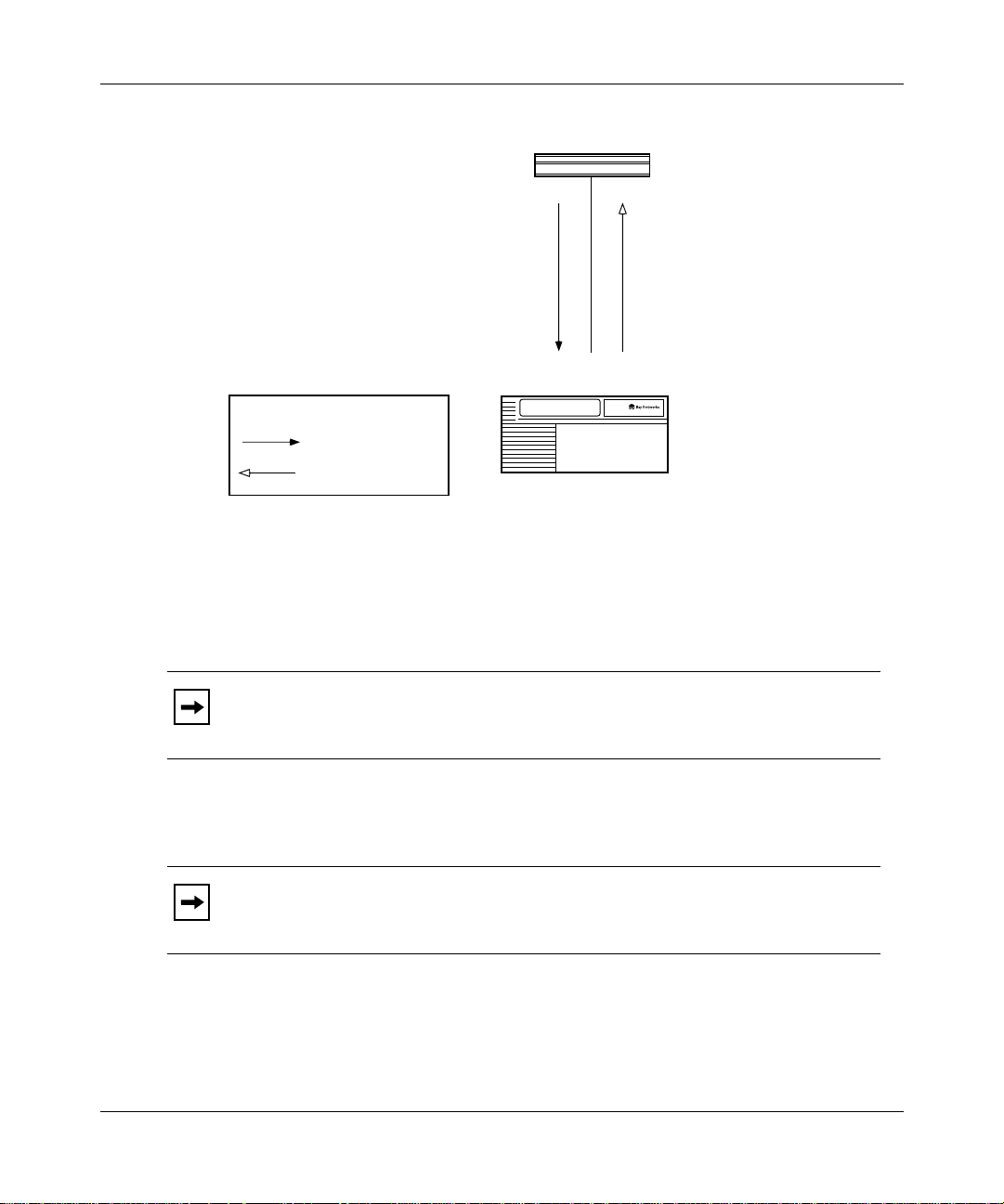
For example, in Figure 1-1, the upstream router’s interface address is
192.32.1.1. This means that the upstream router calculates 192.32.1.2 as
the bootin g router’s IP interface.
308652-14.00 Rev 00
Page 25
Selecting a Boot Configura tio n
ASN router
BOOTP response
with IP address
192.32.1.2
IP address 192.32.1.1
Key
BOOTP request
BOOTP response
Upstream router
CAS0001A
Figure 1-1. Getting an IP Address from a Nortel Networks Standard
Circuit or a Frame Relay PVC in Direct Access Mode
Note:
If the IP address plus 1 equals a broadcast address, the upstream router
calculates the IP addre ss by subtractin g 1. For example, if its interface is
7.255.255.254, the IP interface for the booting router is 7.255.255.253.
b.
A PVC in group access mode references its BOOTP client interface
table to find an associated IP address for the booting router.
Note:
The BOOTP client interface table contains a data link connection
identifier (DLCI) and IP address pair for each PVC. You use Site Manager to
create this table when you follow the instructions in Chapter 3.
308652-14.00 Rev 00
1-7
Page 26
Connecting ASN Routers to a Network
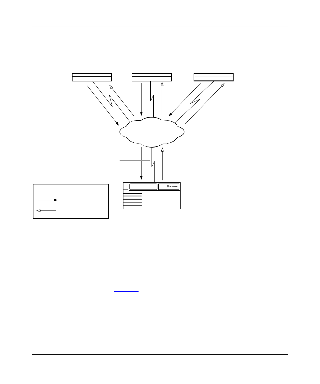
For example, in Figure 1-2, routers 1, 2, and 3 send BOOTP requests for
IP addresses.
Circuit containing three (3) PVCs
(DLCIs 31, 32, and 33 for virtual
connections to routers 1, 2, and 3)
Key
Booting router 2Booting router 1 Booting router 3
Frame Relay
BOOTP request
BOOTP response
Upstream router
CAS0002A
Figure 1-2. Getting an Address from a PVC in Group Access Mode
The upstream router receives the requests on PVCs 31, 32, and 33,
respectively.
The upstream router refers to DLCI 31 in the BOOTP Client Interface
Table (Table 1-2
), finds the IP address (192.32.16.17) associated with the
DLCI, and sends a BOOTP response containing the IP address back to
PVC 31.
The upstream router does the same for the other two circuits.
1-8
308652-14.00 Rev 00
Page 27

Selecting a Boot Configura tio n
Table 1-2. Sample BOOTP Client Interface Table on Upstream Router
DLCI of Incoming BOOTP
Request for IP Address Response
31 192.32.16.17
32 192.32.16.18
33 192.32.16.19
6.
The upstream router sends the IP address and subnet mask to the
booting router in a BOOTP response message.
7.
The ASN assigns the IP address and subnet mask to any synchronous
interface that receives a BOOTP response.
8.
The ASN stores these addresses, along with the address of the next-hop
router, in RAM.
Getting the Software Image and Configuration Files
After it gets the IP addr es s, th e ASN obt ain s it s s oft ware image and conf ig ura ti on
files as follows:
1.
308652-14.00 Rev 00
The ASN sends a BOOTP request for the pathnames of a configuration
file and software image file.
The ASN issues this request simultaneously through all synchronous and
Ethernet interfaces that have IP addresses. It issues this request periodically
through these ports for about 3 minutes, regardless of whether a cable is
connected.
1-9
Page 28
Connecting ASN Routers to a Network
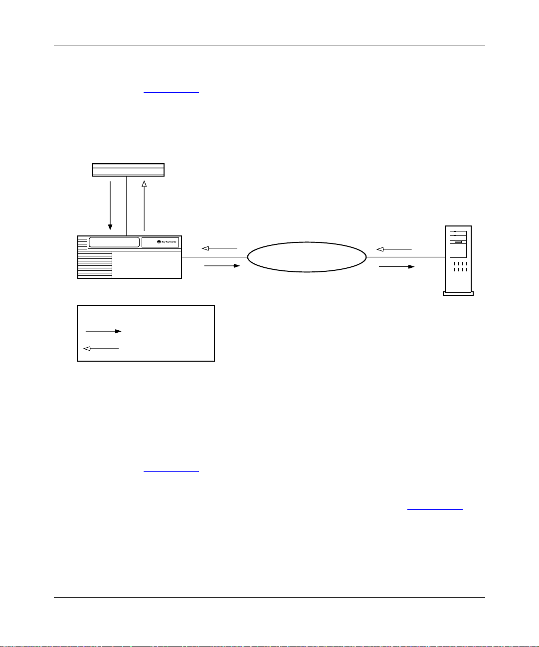
2.
A BOOTP server responds to the router’s request with the directory
pathnames; the ASN stops sending BOOTP requests for the pathnames
(Figure 1-3)
.
The first ASN interface that processes the BOOTP response acts as the TFTP
client in the remaining steps.
ASN router
Key
BOOTP request
BOOTP
server
Pathnames
Corporate backbone
BOOTP response
CAS0003A
Figure 1-3. Getting the Pathnames of the Software Image and Configuration Files
3.
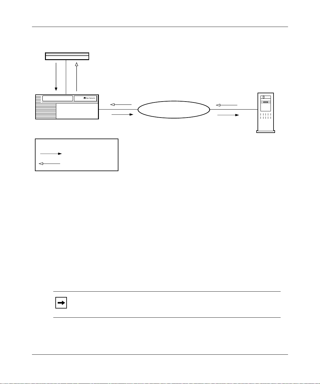
The ASN sends a TFTP request for the configuration file.
4.
The BOOTP server uses TFTP to transfer the configuration file
1-10
(Figure 1-4)
5.
The ASN sends a TFTP request for the image file.
6.
The BOOTP server uses TFTP to transfer the image file (Figure 1-4).
.
308652-14.00 Rev 00
Page 29
Selecting a Boot Configura tio n
ASN router
1. Configuration file
2. Kernel
3. Application files
Corporate backbone
BOOTP server
Key
TFTP request
TFTP response
CAS0004A
Figure 1-4. Getting the Startup Files
7.
The router boots.
8.
The router uses TFTP to get application files as it needs them.
The ASN can continue to request files, even after it begins bridging and
routing traffic.
9.
The router begins bridging and routing network traffic in accordance
with the configuration file.
If a network boot fails, the ASN waits to be booted by a neighboring slot. (A
single-slot A SN will inste ad attempt the Local Boot procedure.)
Note:
The ASN supports Netbooting over multiple slots. The first slot to
retrieve startup files forces the other slots to use those files.
308652-14.00 Rev 00
1-11
Page 30

Connecting ASN Routers to a Network
Selecting the Startup Method
Use the information in the following sections to choose the boot method for both
the initial startup of the ASN and fo r day-to-day operations. Refer to the la st
section of this chapter, “Completing a Network Boot Option
the steps for completing the method you choose.
Booting the Router for the First Time
You coordinate the A SN’s initial startup with a person at the route r s ite, who
physically insta ll s and cables the ASN and initiates the des ir ed startup procedure.
The manual Installing and Maintaining ASN Routers and BNX Platforms
describes these tasks in detail.
Note:
To boot using any method, the asn.exe image must be on the local ASN
file system.
After you select the initial startup configuration (and set up the network as
described in thi s guide), d irect t he person a t the rout er site to be gin th e approp riate
startup option.
,” for a summary of
1-12
Note:
As an alterna tive to ano ther person performing the initial startup at the
remote site, you can perform these tasks using a modem connection.
EZ-Install
EZ-Install is the default option for a new ASN router. You can use EZ-Install for
the initial startup if
• There is a communic ations l ink betwe en the ASN and an ups tream rout er o ver
an HDLC or Frame Relay interface.
• A directory on a BOOTP server contains a customized configuration file for
the ASN.
EZ-Install is the easie st opti on fo r the person a t the ASN si te to pe rf orm, s ince t he
network automatically supplies the IP address and configuration file. This option
does not require a router connection to a modem or console.
308652-14.00 Rev 00
Page 31

Selecting a Boot Configura tio n
Netboot
You can use Netboot if
• The ASN has a communications link to an upstream router over an Ethernet,
HDLC, or Frame Relay interface.
• The ASN has a local console or modem connection.
• A directory on a BOOTP server contains an ASN software image file and a
customized configuration file.
• You provide a network configuration file customized for the ASN.
• You configure an IP address for the ASN’s boot interface.
Netboot takes longer than EZ-Install, but minimizes the cost of line usage and
prevents saturation of the router’s memory.
Local Boot
When you use Local Boot as the initial boot option, the router boots a default
(generic) conf igurati on fil e. You must then comple te the “Quick- Start” inst allation
script to customize the default configuration file and save it locally. Refer to the
manual Quick-Starting Routers.
Recommendations
Even if you cho ose EZ-Inst all, we st rongly reco mmend that you connect a modem
or a console to the router. With a console connection, you can iss ue command s to
the router and displ ay messag es. This is v ery use ful i f you have network problems
after installing the router.
308652-14.00 Rev 00
1-13
Page 32

Connecting ASN Routers to a Network
Booting the Router Routinely
This section compares the Netboot, Directed Netboot, and Local Boot options to
help you choose a boot configuration for routine startups.
Note:
You can use Netboot for some procedures and Local Boot for others,
provided you set up the network to support Netboot.
Netboot
Using Netboot for routine startups allows you to
• Manage software image and configuration files from a remote location by
storing them on the BOOTP server.
This option greatly simplifies the management of a number of routers by
allowing you to conc ent ra te on keeping the startup f il es up to dat e in a si ngl e,
central location -- the BOOTP server.
• Minimize the need to maintain the router’s local file system.
When the router gets file s from a BOOTP server, it stores the files in memory,
not in its file system, reducing the need for frequent file system compactions.
(Refer to Using Technician Interface Software or Configuring and Managing
Routers with Site Manager to learn about file system compaction.)
1-14
• Get application files from the BOOTP server as the ASN needs them.
Getting these files individually, rather than getting the entire asn.exe file,
minimizes the cost of line usage and prevents saturation of the router’s
memory.
One disadvantage of Netboot is that it requires the most time to boot the router.
Directed Netboot
Directed Netboot reduces network traffic and is generally faster than normal
Netboot. On routine startups, the router bypasses the original Netboot BOOTP
negotiation with the BOOTP server for the IP address, software image file, and
configuratio n file, entering the file transfer phase directly, at which time the TFTP
server transfers the startup files to the router.
308652-14.00 Rev 00
Page 33

Selecting a Boot Configura tio n
You use the ifconfig and bconfig commands with the Technician Interface or
Site Manager to define
• The IP address of the TFTP server, using
bconfig
• The router’s IP address, using ifconfig
• The complete pathnames of the startup files that the router will obtain from
the TFTP server, using
bconfig
Directed Ne tboot is usually reserved for starting the router after the initial startup
because you need to know the exact location of the software image and
configuration files.
Local Boot
Local booting for routine startups allows you to
• Minimize the time it takes to boot.
Local boot takes 2 to 3 minutes. Typically, Netbooting an image takes a little
longer. Over a low-speed WAN or after configuring the router to run
numerous protocols, Netbooting an image can take up to 15 or 20 minutes.
It also takes less time to local boot a configuration file than it does to Netboot
one. In most configurations, however, the difference between the two options
is only a few seconds.
• Minimize line usage.
Recommendations
Nortel Networks recommends that you
• Set up the network to support Netboot, e ven if you plan to use the Loc al Boot
• Maintain the software image (asn.exe) on the local file system at all times, in
• Maintain a local configuration file for the ASN, although it is not required to
308652-14.00 Rev 00
Getting files from a BOOTP server adds traffic to your network during the
booting process.
option for the initial configuration and for subsequent restarts.
case you want to use Local Boot to start the ASN.
Netboot the ASN successfully. The presence of a local config file provides
network connectivity if TFTP transfer fails during Netboot.
1-15
Page 34

Connecting ASN Routers to a Network
Completing a Network Boot Option
This section lists the steps required for
• EZ-Install
• Netboot
• Directed Netboot
To proceed with the Local Boot option, go directly to the manual Quick-Starting
Routers.
Note:
To boot an ASN over the network, the ASN must be running Router
Software Version 8.10 or later (or BayStream Software Version 5.00 or later),
and all routers in the path between the ASN and the BOOTP server must be
running Version 7.60 (BayStream 5.00) or later.
EZ-Install
Note:
To use EZ-Install over a Frame Relay circuit, make sure the upstream
router is running BayRS Vers ion 7.80 or lat er (or BayS tr eam Softw are Version
5.00 or later).
1-16
The EZ-Install option requires the following steps:
1.
You use the Configuration Manager in local mode to create a complete
configuration file for the router.
(See Chapter 3 and the manual Configuring and Managing Routers with Site
Manager.)
2.
You set up the network to support BOOTP.
(See Chapter 2.)
3.
You create a BOOTP relay interface table on the upstream router to
support automated addressing, and configure all routers between the
BOOTP server and the booting router as BOOTP relay agents.
(See Chapter 2.)
308652-14.00 Rev 00
Page 35

Netboot
Selecting a Boot Configura tio n
4.
The person at the ASN site installs and boots the router.
(See the manual Installing and Maintaining ASN Routers and BNX
Platforms.)
5.
The ASN gets a software image from the local file system, an IP address
from the upstream router , and the customized configuration file from the
BOOTP server.
(Described in the previous section; no action required.)
If the conf igurat ion f ile mee ts your netw ork requi rements , the ASN starts bridgin g
and routing traffic.
You can use the Site Manager Statistics Manager and Events Manager tools to
verify that the router is routing traffic according to the configuration you want.
(See the manual Configuring and Managing Routers with Site Manager.)
Note:
On a Frame Relay circuit, make sure the upstream router software is
Version 7.71 or later (or BayStream Software Version 6.00 or later).
The Netboot option requires the following steps:
1.
2.
3.
308652-14.00 Rev 00
You use the Configuration Manager in local mode to create a complete
configuration file for the router.
(See Chapter 3 and the manual Configuring and Managing Routers with Site
Manager.)
You set up the network to support BOOTP
.
(See Chapter 2.)
You use Site Manager to enable BOOTP on each router interface in the
path between the router and the BOOTP server.
(See Chapter 2.)
1-17
Page 36

Connecting ASN Routers to a Network
4.
The person at the ASN site establishes a Technician Interface session (or
you establish a session via modem).
(See the manual Installing and Maintaining ASN Routers and BNX
Platforms.)
5.
The person at the ASN console uses the
bconfig
and
ifconfig
commands
to configure a synchronous or Ethernet interface.
(See Chapter 4 and the manual Installing and Maintaining ASN Routers and
BNX Platforms.)
6.
You install the
netboot.exe
file in the BOOTP server’s file system, and
make sure the image and application files reside in the same directory.
(See Chapter 2.)
7.
The person at the router site boots the router.
(See the manual Installing and Maintaining ASN Routers and BNX
Platforms.)
After the router boots, it gets a configuration file from a BOOTP server and
loads the software image from the local file system.
If the configuration file meets your network requirements, the router starts
bridging and routing traffic.
You can use the Site Manager Statistics Manager and Events Manager tools to
verify that the router is routing traffic according to the configuration you want.
(See the manual Configuring and Managing Routers with Site Manager.)
1-18
308652-14.00 Rev 00
Page 37

Directed Netboot
Note:
Router Software Vers ion 8.10 or later (or BayStream Softwar e Vers ion 5.00 or
later).
The Directed Netboot option requires the following steps:
1.
You use the Configuration Manager in local mode to create a complete
configuration file for the router.
(See Chapter 3 and the manual Configuring and Managing Routers with Site
Manager.)
2.
You set up the network to support TFTP.
(See Chapter 2.)
3.
The person at the ASN site establishes a Technician Interface session (or
you establish a session via modem).
(See the manual Installing and Maintaining ASN Routers and BNX
Platforms.)
Selecting a Boot Configura tio n
To use Directed Netboot, make sure the upstream router is running
4.
5.
The router starts bridging and routing traffic.
You can use the Site Manager Statistics Manager and Events Manager tools to
verify that the router is routing traffic according to the configuration you want.
(See the manual Configuring and Managing Routers with Site Manager.)
308652-14.00 Rev 00
The person at the ASN console issues
bconfig
and
ifconfig
commands to
configure a synchronous or Ethernet interface for Directed Netboot.
(See Chapter 4 if you are using a remote Technician Interface session, or the
manual Installing and Maintaining ASN Routers and BNX Platforms if at the
ASN site.)
The person at the router site boots the router.
(See the manual Installing and Maintaining ASN Routers and BNX
Platforms.)
The router boots from a local software image and downloads the
configuration file from a TFTP server.
1-19
Page 38

Page 39

Chapter 2
Setting Up a UNIX Boot Server
To support network booting, you need to set up a UNIX workstation on the
network. This chapter describes what you need to do at the UNIX workstation to
prepare for booting an ASN over the network.
When a router boots over the netw ork, it get s necess ary sta rtup f iles from a UNIX
server. When the ASN uses EZ-Install or Netboot, the server supplies
configuration file and/or software image file pathnames using Boot Protocol
(BOOTP). The ASN then retrieves the files using Trivial File Transfer Protocol
(TFTP). When the ASN uses Directed Netboot, it already knows the pathnames of
the files it needs and retrieves the files directly from the server using TFTP.
To configure EZ-Install or Netboot, complete the steps in both “Setting Up a
BOOTP Serv er” and “Setting Up a TFTP Serv er.” To con f i gure Direc ted Net boot,
complete the steps in “Setting Up a TFTP Server
Setting Up a BOOTP Server
To support EZ-Install or Netboot, an ASN needs a network connection to a
BOOTP server. You configure a UNIX workstation as a BOOTP server by
• Setting up BOOTP sockets
• Configuring BOOTPD (the BOOTP daemon)
Note:
A daemon is an unattended process (that is, one that runs in the
background). An applica tion typical ly calls up a daemon to perform a st andard
routine or service (in this case, BOOTP).
On Sun workstations, you must first copy the BOOTPD program to the
appropriate directory.
308652-14.00 Rev 00
.”
2-1
Page 40

Connecting ASN Routers to a Network
Copying the BOOTPD Program on Sun Workstations
Depending on the operating system you use, Nortel Networks may or may not
ship BOOTPD with the Site Manager package. The AIX and HP-UX operating
systems already have BOOTPD. SunOS and Solaris
Manager automatically installs BOOTPD on Sun workstations running SunOS
and Solaris.
Copy the bootpd file to the /etc directory as follows:
do not, however, so Site
1.
Log in to the UNIX workstation as
2.
Enter the following command:
cp /usr/wf/bin/bootpd /etc
Setting Up BOOTP Sockets
A socket is a UNIX mechanism for cr eating virtu al connection s between operati ng
system and netwo rk pro ces ses. For each soc k et , the /etc/s ervices file must include
a user datagram protocol (UDP) descriptor that provides process-to-process
addressing information.
Set up the send and receive sockets for the BOOTP process as follows:
1.
Log in to the UNIX workstation as
2.
Use a text editor to insert the f ollowing tw o l ines into the
bootps 67/udp # bootp server
bootpc 68/udp # bootp client
Setting Up BOOTPD to Run
root
root
.
.
/etc/services
file:
2-2
Configure your workstation to run the BOOTPD program when it receives a
BOOTP request packet, as follows:
1.
2.
root
As
, use a text editor to open the
Make sure that no other line in the file begins with “bootps.”
/etc/inetd.conf
file.
308652-14.00 Rev 00
Page 41

If there is such a line, your workstation is already configured as a BOOTP
server. Comment out this line b y entering a pound s ign (#) at the beginning of
the line, so that the server will use the BOOTPD program that you specify in
the next step.
3.
Insert the following line anywhere in the file to configure your
workstation as a BOOTP server:
bootps dgram udp wait root /etc/bootpd bootpd
4.
Save and exit the file.
Setting Up BOOTPD to Respond to Routers
When the operating system receives a BOOTP packet, it starts up BOOTPD. The
BOOTPD softw are matche s the source IP address of the pack et to an IP addr ess in
its BOOTP table (bootptab) file to determine the pathnames to configuration and
boot image files.
Note:
The bootptab file can include the same boot image pathname for all
booting routers, or a different boot image for each IP addresses.
Setting Up a UNIX Boot Server
Entries in bootptab also include optional parameter tags. Nortel Networks
supplies a sample bootptab file that Site Ma nager installs automatically in the
/usr/wf/con fig directory. Use a cop y of thi s sample f ile i f you do not already hav e a
bootptab file.
Set up BOOTPD to respond to booting routers, as follows:
1.
2.
3.
308652-14.00 Rev 00
file.
/etc
directory to determine whether it
root
As
, view the contents of the
already contains a
bootptab
If it does contain a bootptab file, disregard Steps 2 and 3 and continue with
Step 4 to edit this file.
Issue the following command to copy the
bootptab
file to the
/etc
directory:
cp /usr/wf/config/bootptab /etc
Use an editor to open the
bootptab
file in the
/etc
directory.
2-3
Page 42

Connecting ASN Routers to a Network
4.
Type the information that pertains to the ASNs in your network into the
bootptab
file.
The section that follows explains how to format your entries. Use Tables 2-1
and 2-2
to determine which tags and values you need. Figure 2-1 shows the
sample bootptab file include d with th e Site Manage r soft war e. The comment s
in this file explain the sample definitions.
5.
After editin g the
Be sure the bootp tab file resides in the /etc directory . BOOTPD fails if it
Note:
bootptab
file, be sure to save the changes.
cannot find the bootptab file in /etc.
Editing the bootptab File
Enter a
<hostname>
definition in the bootpt ab f il e for ea ch ASN in your ne tw ork.
The format of each definition in the bootptab file is as follows:
<hostname>:\
:<tg>=<value>:\
:<tg>=<value>:\
:<tg>=<value>:
•
<
hostname
>
is a name you a ss ign t o a BOOTP cl ient. (Each router is a client.)
• <tg> is a BOOTP parameter name (tag).
• Follow each tag with an equal sign (=) and a value.
2-4
• A pound sign (#) at the beginning of a line indicates a comment.
• A backslash (\) at the end of a line indicates continuation of the line.
Make sure you enter a backslash (\), not a slash (/), at the end of every
Note:
line that does not conclude a definition.
308652-14.00 Rev 00
Page 43

Setting Up a UNIX Boot Server
Keep the following in mind when editing bootptab:
<
•The
hostname> definition can contain a maximum of 79 characters.
• The first character must be alphabetic.
• All characters must be alphanumeric.
• You can use a dot (.) to separate characters, but the character immediately
following the dot must be alphabetic.
• The hostname definition cannot contain an underscore.
Table 2-1
lists the tags for router host names. Table 2-2 lists the tags for boot
image names.
Table 2-1. BOOTPD Tags for a Router Host Name
Required or
Tag
ip Required IP address -- the ho st IP address
sm Optional Subnet mask -- the host subnet
T129 Required Pathname of the router
T130 Required Size of the router configur a tion fil e
tc Optional Table continuation -- pointer to a
Optional Value Example
of the router.
mask of the router.
configuration file. The maximum
path length is 49 characters.
in 512-byte blocks. The setting of
this tag determines how much
memory the router allocates for
the file. Set this tag to 0x0004.
definition in another location in the
same file f or additional inf ormation.
The info rmation this tag points to is
common to all route r s t hat need to
boot using BOOTP. If information
in a definition for a specific router
is inconsistent with the definition
this tag points to, BOOTPD uses
the information for the specific
router.
ip=192.32 .5.2
sm=255.255.255.0
T129="/usr/cfg/
asn_Bost.cfg"
T130=0x0004
tc=general
308652-14.00 Rev 00
2-5
Page 44

Connecting ASN Routers to a Network
Table 2-2. BOOTPD Tags for a Boot Image Name
Required
Tag
or Optional Value Example
hd Required Home directory -- the directory on
the workstation conta ining the boot
files. By default, the Image Builder
writes it s files to the directory
specified in the example. The
rel...
number of the current router
software release. If you change
the default or move the files to
another director y, specify that
directory.
bf Required Boot file -- the name of the boot
image.
bs Required Boot size
in 512-oct et blocks. If you specify
auto as the size, the BOOTP
server calculates the size of the
file for each BOOTP request.
vm Required Vendor magic cookie selector
the BOOTP server should always
reply in a manner compliant with
RFC 1048. You must enter
rfc1048
router can understand the BOOTP
responses it receives.
number is the versi on
-- the size of the boo t file
for this tag, so that the
--
hd=/$HOME/.builder_di r/
rel900/asn
bf=krnl_asn.exe
bs=auto
vm=rfc1048
2-6
The following sample bootptab file (Figure 2-1) enables two ASNs (named
“ASN.Boston” and “ASN.Chicago”) to boot across the network. Use the basic
format shown in Figure 2-1 to set up your own bootptab file.
308652-14.00 Rev 00
Page 45

Setting Up a UNIX Boot Server
# This file contains the default specification for the boot
# image file to be used by all ASNs.
# "general" contains information that is common to all ASNs
# that need to boot via BOOTP. You can use any word in place
# of "general."
general:\
# "hd" specifies that /$HOME/.builder_dir/re900/asn is the
# directory on the workstation where the boot files are
# located. By default, the Image Builder writes its files to
# this directory. If you are using a router software version
# later than 7.80, add the associated three digits to the end
# of the "rel" directory name. If you moved the files to
# another directory, specify that directory.
:hd=/$HOME/.builder_dir/rel900/asn:\
# "bf" specifies that the name of the boot image kernel file
# is krnl_asn.exe.
:bf=krnl_asn.exe:\
# "bs" indicates the size of the boot file. If you specify
# "auto" as the size, the BOOTP server calculates the size of
# the file for each BOOTP request.
:bs=auto:\
# "vm" indicates that the BOOTP server should always reply in
# a manner compliant with RFC 1048. You must enter rfc1048
# for this tag so that the ASN can understand the BOOTP
# responses it receives.
:vm=rfc1048:
# This line marks the beginning of the active definition for
# the ASN we are naming "ASN.Boston."
ASN.Boston:\
# "ip" indicates the IP address of the ASN.
:ip=192.32.5.2:\
# "T130" indicates the size of the ASN’s configuration file in
# 512-byte blocks. Always use 0x0004.
:T130=0x0004:\
# "T129" indicates the pathname of the configuration file
# for the ASN.
:T129="/usr/cfg/ASN_Bost.cfg":\
# "tc" indicates that the "general" definition contains more
# information that applies to BOOTP transmissions to
308652-14.00 Rev 00
2-7
Page 46

Connecting ASN Routers to a Network
# "ASN.Boston."
:tc=general:
# This is the active definition for the ASN we are naming
# "ASN.Chicago."
ASN.Chicago:\
:ip=10.0.0.4:\
:T130=0x0004:\
:T129="/usr/cfg/ASN_Chic.cfg":\
:tc=general:
Figure 2-1. Sample
bootptab
File
Verifying Consistent BOOTP Service
You may want to configure a second workstation as a BOOTP server for backup
purposes. If you do so, make sure the two bootptab files match exactly. Also,
make sure that the image and string files are from the same software version.
Setting Up a TFTP Server
An ASN needs a network connection to a TFTP server to complete EZ-Install,
Netboot, or Directed Netboot. You configure a UNIX workstation as a TFTP
server by
• Setting up TFTPD (the TFTP daemon)
• Adding a TFTP user (for an HP 9000 only)
• Setting up static routes to routers (optional)
• Loading the changes into memory
Note:
A daemon is an unattended process (that is, one that runs in the
background). An applica tion typical ly calls up a daemon to perform a st andard
routine or service (in this case, TFTP).
2-8
When you set up the TFTPD server on a UNIX workstation, you can allow TFTP
to access the root dir ectory a nd an y subd irector y or res trict its acc ess to a speci f ied
directory or pathname.
308652-14.00 Rev 00
Page 47

Allowing the router to access the root directory and any subdirectory is the
simpler procedure. Specifying a pathname provides security, but it requires
linking TFTPD.
Providing TFTPD Access to the Root Directory
To provide TFTPD access to files in the root directory and to all subdirectories,
verify or i nsert th e approp riate l ine for your opera ting syst em in the /etc/inetd.conf
file.
Setting Up a UNIX Boot Server
Refer to the sample line for your operating system in Table 2-3
Table 2-3. Providing TFTPD Access to Root and All Subdirectories
Operating System Sample Line to Insert in /etc/inetd.conf File
SunOS tftp dgram udp wait root /usr/etc/in.tftpd in.tftpd -s /
Solaris tftp dgram udp wait root /usr/sbin/in.tftpd in.tftpd -s /
HP-UX tftp dgram udp wait root /etc/tftp tftp
AIX Use the System Management Interface Tool (SMIT) to configure TFTP. For
instructions, refer to the IBM guides on TCP/IP daemons and the TFTP protocol.
.
Restricting TFTPD Access to a Specified Directory
To restrict TFTPD file access to a specific directory , insert the appropr ia te line for
your operating system in the /etc/inetd.conf file.
The examples in Table 2-4
substitute any directory you want.
Table 2-4. Restricting TFTPD Access to One Directory
Operating System Sample Line to Insert in /etc/inetd.conf File
restrict access to the /tftpboot directory. You can
SunOS tftp dgram udp wait root /usr/etc/in.tftpd in.tftpd -s /tftpboot
Solaris tftp dgram udp wait root /usr/sbin/in.tftpd in.tftpd -s /tftpboot
HP-UX tftp dgram udp wait root /etc/tftp tftp -s /tftpboot
AIX Use the System Management Interface Tool (SMIT) to configure TFTP. For
instructions, refer to the IBM guides on TCP/IP daemons and the TFTP protocol.
308652-14.00 Rev 00
2-9
Page 48

Connecting ASN Routers to a Network
Creating Links
You must create a symbolic link for every pathname you specify in the bootptab
file. For example, to set up the symb olic links for the /tftpboot path, use the
following procedure:
1.
Log in to your UNIX workstation as
2.
Enter the following commands:
cd tftpboot
ln -s . usr
ln -s . tftpboot
Caution:
Do not insert a slash (/) in the
link cannot contain references to directories above the directory specified in
tftpd
the
command line. Use the -s flag to provide a dditional security to your
network. (This flag restricts TFTPD access to a specified directory.)
Adding a TFTP User for an HP 9000
Follo w the ins truct ions i n this secti on only if you are usi ng an HP 9000 as the Site
Manager workstation.
T o add a TFTP u ser for t he HP 9000, ent er a line wit h the fol lo wing sy ntax in your
/etc/passwd file. We recommend that you use root (/) as the TFTP home directory.
tftp::
<user_id>:<group_no.>
::/:/bin/false
root
.
cd tftpboot
command; a symbolic
2-10
For example:
tftp::510:20::/:/bin/false
Note:
We recommend that you not use the System Administration Manager
(SAM) utility as an alternative to editing the /etc/passwd file.
308652-14.00 Rev 00
Page 49

Setting Up Static Routes to Next-Hop Routers
If your workstation requires static routes, use this section to specify a path to the
network by
• Editing the inetd.conf file
• Verifying the rout es
• Loading the changes into memory
You must set up a static route for each path between the routers and the BOOTP
server’s next-hop router.
You may want to specify a static route in a multihop environment or in an
environment using routing protocols such as RIP, where minor routing update
delays may extend the time it takes to Netboot.
Editing the inetd.conf File
Add the fol lowing line to the inetd.conf file to set up a static route:
Setting Up a UNIX Boot Server
route add
<
destination> is the IP address of the ASN or its network.
<
gateway> is the IP address of the network destination to which packets are to be
<destination> <gateway> <hops>
addressed.
<
hops> is the number of hops to the network destination.
Verifying the Routes
After adding a stat ic ro ute for ea ch path to the b oot ing rou ters, ent er the following
command to display the routing table and verify the route you added:
netstat -r
308652-14.00 Rev 00
2-11
Page 50

Connecting ASN Routers to a Network
Loading the Changes into Memory
Once you modify the inetd .conf fi le, you must force th e operating system to reread
it by rebooting the workstation or by issuing a hang-up signal.
In most cases, reboot the workstation. Issue a hang-up signal if the workstation is
performing a task that you do not want to interrupt.
Rebooting
Reboot your workstation as follows:
1.
Log in as
2.
Execute the following command:
/etc/shutdown now -r
root
.
The -r flag reboots the workstation.
Issuing a Hang-Up Signal
Issue a hang-up signal as follows:
1.
Log in as
2.
Execute the following command to hang up on the
ps -aux | grep inetd
root
.
inetd
process:
The system displays a line s imilar to this one:
root 148 0.0 0.0 48 0 ? IW Jan 14 0:07 inetd
3.
Execute the following command, using the first number in the line after
the word “root” (in this case, 148):
kill -1 148
The inetd process rereads the inetd.conf file.
What to Do Next
Before you can use t he net w ork to boot an ASN, you mu st al so comple te the st eps
in Chapter 3.
2-12
308652-14.00 Rev 00
Page 51

Chapter 3
Configuring Network Booting
This chapter describes how to use Site Manager to configure network booting for
routers in the network.
Note:
Before the router can get files over the network, you must also set up a
UNIX server on the network, as described in Chapter 2.
Sections of this cha pter expl ain ho w to complete t he tasks re quired for conf iguri ng
EZ-Install, Netboot, or Directed Netboot.
To Configure This Boot Method Complete This Section
EZ-Install, Netboot, or Directed Netboot “Preparing Configuration and Image Files”
Netboot or Directed Netboot “Enabling Netboot or Directed Netboot
Netboot or Directed Netboot “Configuring a Netboot Interface
Netboot “Setting Up Routing Paths
EZ-Install over Frame Relay
group-access PVC
Note:
Site Manager connection with the ASN. Refer to Chapter 4 and to Installing
and Maintaining ASN Routers and BNX Platforms for information about
making the ASN initial Site Manager connection.
308652-14.00 Rev 00
”
“Creating a BOOTP Client Interface Table
The steps in this chapter assume a local, dynamic, or remote
”
”
“
3-1
Page 52

Connecting ASN Routers to a Network
Preparing Configuration and Image Files
Unless the ASN will use the default (ge neric) configuration file and software
image that ship on its local file system, you must create
• A unique configuration file for each remote router
• A uniform software image that all routers in your network can use
Creating Configuration Files
Prepare network configuration files as follows:
1.
Use the Configuration Manager in local mode to create a configuration
file for each ASN.
Refer to Configuring and Managing Routers with Site Manager for
instructions.
2.
Record the name of each configuration file and corresponding ASN for
later refere nce.
When you name configuration files, keep the following in mind:
3-2
• Configuration files that you save on a BOOTP server do not have to be
named config.
• Configuration filenames must begin with an alphabetical character. The
remaining characters must be alphanumeric and may also include the
underscore (_) character. You cannot use spaces.
• Configurati on filenames can consist of 1 to 15 chara ct ers , incl udi ng a dot
(.). We recommend that you limit filenames to eight characters to ensure
that all operating systems Nortel Networks supports can recognize the
names.
• Configuration filename extensions are optional and must follow a
filename and a dot. We recommend that you limit filename extensions to
three characters.
• BOOTP allows a maximum number of 49 characters in a path, including
slashes, filename, optional dot, and filename extension.
3.
If the BOOTP server and Site Manager do not reside on the same
workstation, transfer the configuration files to the BOOTP server.
308652-14.00 Rev 00
Page 53

Preparing an Image
If you want the ASN to automatically boot a network image when starting up
(using EZ-Install, Netboot, or Directed Netboot), you must use the Site Manager
Image Builder to change the default setting before you attempt to start up.
Note:
BayStream software does not support Image Builder.
To use Image Builder:
1.
On the Site Manager workstation, open the software image file in the
Image Builder.
Keep the following in mind:
• Be sure to select the correct image. If you select an image for another router
type, you cannot generate the corre ct f iles.
• If you configure the router to obtain its image from the network, it cannot
Netboot the image until the kernel image is available on the BOOTP server.
• Make sure that you extract the software image and all the application (.exe)
files in the ASN directory. The files must be from the same software image
file whose components were created from the same version of software. If
these files are from different softwa re versions, the router may fail to boo t or
operate properly.
• Refer to Configuring and Managing Routers with Site Manager for more
instructions.
Configuring Network Booting
2.
308652-14.00 Rev 00
After you open the image file, the Image Builder automa tically gener ates the
kernel image and application files.
By default, the Image Builder stores these files in /$HOME/.builder_dir/
rel
<
rel>/asn (where <rel> is the current router software release for the router).
For example, Version 3.00 of the Site Manager Image Builder tool stores
Version 9.00 files for an ASN in the /$HOME/.builder_dir/rel900/asn
directory.
For additional instructions on how to use the Ima ge Builder, refer to
Configuring and Managing Routers with Site Manager.
If you use a different workstation as a BOOTP server, transfer all of the
files in the directory that contains the kernel file to the new workstation.
3-3
Page 54

Connecting ASN Routers to a Network
Enabling Netboot or Directed Netboot
By default, the router obtains its software image from its local file system and its
configuration file from a BOOTP server. You can display and change these
settings as follows:
1.
Select Protocols > Global Protocols > Net Boot > Global from the
Configuration Manager window (Figure 3-1)
.
Figure 3-1. Displaying the Netboot Interfaces Window
The Edit Netboot Global Parameters window appea rs (Figure 3-2).
3-4
308652-14.00 Rev 00
Page 55

Configuring Network Booting
Figure 3-2. Edit Netboot Global Parameters Window
2.
To enable Netboot, specify Enable for at least one of the first two
parameters.
3.
To enable Directed Netboot, spec ify Enable f or at least one o f the f irst two
parameters and configure each of the last three parameters.
For guidelines, see the follow ing parameter descriptions.
4.
Click on OK to apply parameter edits.
308652-14.00 Rev 00
3-5
Page 56

Connecting ASN Routers to a Network
Netboot and Directed Netboot Parameters
Note:
Of the five parameter fields shown in Figure 3-2, the first two (Boot
Image From Network and Boot Config From Network) apply to both Netboot
and Directed Netbo ot. The la st t hree p ara meters are for Dire cted Ne tbo ot onl y.
Parameter: Boot Image From Network
Path: Configuration Manager > Protocols > Global Protocols > Net Boot >
Global
Default: Disable
Options: Enable
Function: Enables or disables retrieval of the software image from the BOOTP
server the next time the router starts up.
Instructions: Set to Disable if you w ant to boot us ing th e i mage in the route r’s local file
system. This setting reduces the time it takes to boot the router and
eliminates using network bandwidth to obtain the image.
Set to Enable if
• You want the router to obtain the image from a BOOTP server and
• You are upgrading the image on a number of routers. The routers can
MIB Object ID: 1.3.6.1.4.1.18.3.3.2.10.1.1
Note:
As an alternative to enabling the Boot Image From Network parameter,
you can use the Router Files Manager to transfer an upgraded image to the
ASN. To do this, delete the ASN’s software image file, compact the file
system, and copy the upgraded image file to the ASN. Use the Router Files
Manager to confirm that the upgraded image on the router is the same size as
that on the Site Manager workstation. This verifies that th e file transfer was
successful.
Disable
|
you have already set up the network to support BOOTP service.
then boot using a single image on the BOOTP server. You must
ensure that the directory name in the bootptab file matches the
location of the upgraded image before you boot the routers.
3-6
308652-14.00 Rev 00
Page 57

Configuring Network Booting
Parameter: Boot Config From Network
Path: Configuration Manager > Protocols > Global Protocols > Net Boot >
Global
Default: Enable
Options: Enable
Disable
|
Function: Enables or disables retrieval of the configuration file from a BOOTP
server the next time the router starts up.
Instructions: Set to Disable if you have already saved the configuration file in memory
to the router’s local file system, and you want to boot using this
configuration file. This setting reduces the time it takes to boot the router
and eliminates using network resources to obtain the configuration file.
Set to Enable if you w a nt the router to obt ain th e co nf igur atio n f i le fr om a
BOOTP server and you have already set up the network to support
BOOTP service.
MIB Object ID: 1.3.6.1.4.1.18.3.3.2.10.1.2
Parameter: Boot Server Address
Path: Configuration Manager > Protocols > Global Protocols > Net Boot >
Global
Default: None
Options: A valid IP address of a TFTP server
Function: When one or both of the para mete rs Boot Image From Network a nd Boo t
Config From Network are set to Enable, this parameter specifies the
TFTP server from which the router will obtain the boot image and boot
configuration files.
Instructions: Use this parameter only when configuring Directed Netboot. Enter the
valid IP address of the TFTP server, in dotted decimal notation.
MIB Object ID: 1.3.6.1.4.1.18.3.3.2.10.1.3
308652-14.00 Rev 00
3-7
Page 58

Connecting ASN Routers to a Network
Parameter: Boot Image Pathname
Path: Configuration Manager > Protocols > Global Protocols > Net Boot >
Global
Default: None
Options: A valid image file pathname
Function: When the parameter Boot Image From Network is set to Enable, this
parameter specifies the absolute pathname of the boot image file on the
TFTP server.
When you Netboot the router, this parameter shows the full path to the
active image on the remote server. When you boot an ASN locally, the
name of the acti ve image ( wfHwEntry .wfHwActiveIma geName) a ppears in
the form <volume>:<image name>.
Instructions: Use this parameter only when configuring Directed Netboot. Make sure
the file you specify is the valid image file on the TFTP server.
MIB Object ID: 1.3.6.1.4.1.18.3.3.2.10.1.4
Parameter: Boot Config Pathname
Path: Configuration Manager > Protocols > Global Protocols > Net Boot >
Global
Default: None
Options: A valid configuration file pathname
Function: When the parameter Boot Config From Network is set to Enable , this
parameter specifies the absolute pathname of the boot configuration file
on the TFTP server.
Instructions: Use this parameter only when configuring Directed Netboot. Make sure
the file you specify is the valid configuration file on the TFTP server.
MIB Object ID: 1.3.6.1.4.1.18.3.3.2.10.1.5
3-8
308652-14.00 Rev 00
Page 59

Configuring a Netboot Interface
When you enable Netboot or Directed Netboot, you must configure one or more
of the ASN’s circuits as a Netboot interface. If you are using EZ-Install, you do
not need to configure Netboot interfaces.
Follow these instructions to add a Netboot interface.
1.
Select Protocols > Global Protocols > Net Boot > Interfaces from the
Configuration Manager window.
Configuring Network Booting
The Netboot Interfaces window appears (Figure 3-3)
.
Figure 3-3. Netboot Interfaces Window
2.
308652-14.00 Rev 00
The scroll box is empty unless this router has existing Netboot interfaces
configured.
Click on Add.
The Netboot Interface window appears (Figure 3-4
).
3-9
Page 60

Connecting ASN Routers to a Network
Figure 3-4. Netboot Interface Window
3.
Enter the appropriate slot number, module number, and port number
(connector identification).
For guidelines, see the Netboot Interface parameter descriptions that follow
these instructions.
3-10
Note:
If you configure mor e tha n one ci rcuit for Netboot, the f i rst to receiv e a
reply from the BOOTP server will use Netboot to reach the router.
4.
Click on OK in the Netboot Interface window (Figure3-4).
The slot number, module number, and connector identification of the
configured interface now appear in the scroll box of the Netboot Interfa ces
window (Figure 3-3)
.
308652-14.00 Rev 00
Page 61

Netboot Interface Parameters
Parameter: Slot Number
Path: Configuration Manager > Protocols > Global Protocols > Net Boot >
Interfaces
Default: None
Range: 1 to 4
Function: Specifies the assigned slot number for the physical slot in which the net
module for this connector is installed.
Instructions: Type the appropriate slot number in the Slot Number box.
MIB Object ID: None
Parameter: Module Number
Path: Configuration Manager > Protocols > Global Protocols > Net Boot >
Interfaces
Configuring Network Booting
Default: None
Range: 1 to 4
Function: Specifies which net module supports the connector.
Instructions: Type the appropriate module number in the Module Number box.
MIB Object ID: None
308652-14.00 Rev 00
3-11
Page 62

Connecting ASN Routers to a Network
Parameter: Connector
Path: Configuration Manager > Protocols > Global Protocols > Net Boot >
Interfaces
Default: None
Options: COM1
COM2 | XCVR1 | XCVR2
|
Function: Identifies the connector configured as a Netboot interface.
Instructions: Enter the c onnect or na me f or t he Net boot in terf ace . To use Netboot o v er a
synchronous interface, enter COM1 or COM2. To use Netboot over an
Ethernet interface, enter XCVR1 or XCVR2.
MIB Object ID: None
Parameter: Connector IP Address
Path: Configuration Manager > Protocols > Global Protocols > Net Boot >
Interfaces
Default: None
Options: Any valid IP address
Function: Specifies the IP address of the remote netbooting router that is using
EZ-Install. This parameter applies only to a Frame Relay group access
PVC connection.
Instructions: Enter the IP address of the remote netbooting router’s interface, in dotted
decimal notation.
MIB Object ID: 1.3.6.1.4.1.18.3.3.2.10.3.1.4
3-12
308652-14.00 Rev 00
Page 63

Parameter: Connector Subnet Mask
Path: Configuration Manager > Protocols > Global Protocols > Net Boot >
Interfaces
Default: None
Options: The Configuration Manager automatically calculates an appropriate
subnet mask, depending on the cl ass of the netw ork to which the i nterface
connects. However, you can change the subnet mask with this parameter.
Function: Specifies the network and subnetwork portion of the 32-bit IP address of
this interface.
Instructions: Either accept the assigned subnet mask or enter another subnet mask, in
dotted decimal notation.
MIB Object ID: 1.3.6.1.4.1.18.3.3.2.10.3.1.5
Parameter: Connector Next Hop
Path: Configuration Manager > Protocols > Global Protocols > Net Boot >
Interfaces
Configuring Network Booting
Default: None
Options: Any valid IP address
Function: Specifies the IP addr ess of the next-hop router connected to this inte rf ac e.
When the router sta rts u p, the ne xt-h op rout er pa sses the BOOTP requests
and responses that initiate the transfer of the image or configuration file
between the router and the BOOTP server. If the router and BOOTP
server are on the same IP subnet, you do not have to set this parameter.
Instructions: Enter the IP address of the next-hop router connected to the interface you
are adding, in dotted decimal notation.
MIB Object ID: 1.3.6.1.4.1.18.3.3.2.10.3.1.6
308652-14.00 Rev 00
3-13
Page 64

Connecting ASN Routers to a Network
Parameter: Connector Protocol Mask
Path: Configuration Manager > Protocols > Global Protocols > Net Boot >
Interfaces
Default: Point to Point
Options: Point to Point
Annexa
Function: During the boot process the router will configure the synchronous
interface to the specified protocol.
Instructions: Specify the desired protocol option.
MIB Object ID: 1.3.6.1.4.1.18.3.3.2.10.3.1.7
Parameter: Connector State
Path: Configuration Manager > Protocols > Global Protocols > Net Boot >
Interfaces
Default: Enable
Options: Enable
Function: Enables or disables the connector parameters. If you set this parameter to
Disable, the router cannot Netboot.
Instructions: If you do not want to use the settings on the Netboot Interfaces window,
select Disable. You must set this parameter to Enable to use any of the
other four parameters in the window.
MIB Object ID: 1.3.6.1.4.1.18.3.3.2.10.3.1.1
|
Point to Point Internal Clock | Fr Relay Anne xd | Fr Relay
|
Fr Relay LMI
|
Disable
3-14
308652-14.00 Rev 00
Page 65

Setting Up Routing Paths
You set up the routing path between a BOOTP server and a booting routers by
• Enabling BOOTP relay interfaces on all routers between the server and the
booting router
• Creating a BOOTP Relay Agent Forwarding Table for each router in the path
• Creating a BOOTP Client Interface Table for the upstream router when the
booting router is on a Frame Relay PVC in group access mode
Note:
If you are booting over an Ethernet LAN and the Site Manager
workstation is directly cabled to the LAN, you do not need to configure a
BOOTP routing path.
Enabling Relay Interfaces
You must enable BOOTP relay (also called BOOTP pass-through or gateway) on
all interfaces in the paths between the booting routers and the BOOTP server.
Figure 3-1 shows an example of a network with BOOTP gateways.
Configuring Network Booting
308652-14.00 Rev 00
3-15
Page 66

Connecting ASN Routers to a Network
Router A
Enable BOOTP on
these interfaces
Router B
Corporate backbone
Router C
BOOTP
server
CAS0006A
3-16
Table 3-1. Enabling BOOTP in a Sample Network
Enable BOOTP relay on an interface as follows:
1.
Click on the connector in the Configuration Manager window.
2.
Select Edit Circuit in the Edit Connector window.
3.
Select Protocols > Add in the Circuit Definition window.
4.
Select BOOTP in the Select Protocols window and click on OK.
5.
Select File > Exit to exit the Circuit Definition window.
308652-14.00 Rev 00
Page 67

Creating BOOTP Relay Agent Forwarding Tables
You must create a BOO TP Relay Ag ent Fo rwar ding Table for ev ery rout er passi ng
BOOTP traffic between the router and the BOOTP server.
The BOOTP Relay Agent F orw ardi ng Table allows you to spec ify the IP inter fa ce
that receiv es the inco ming BOO TP request pa ckets, and t he associated IP int erface
that forwards them. You can add multiple pairs of incoming and outgoing
interfaces to support connections to multiple routers in your network.
To create the BOOTP Relay Agent Forwarding Table, begin at the Configuration
Manager wind ow and complete the following steps.
1.
Select Protocols > IP > BOOTP > Relay Agent Interface Table in the
Configuration Manager window (Figure 3-5)
Configuring Network Booting
.
Figure 3-5. Displaying the BOOTP Relay Agent Interface Table
The BOOTP Relay Agent Interface Table window appears (Figure 3-6). This
window lists all IP interfaces on the router.
308652-14.00 Rev 00
3-17
Page 68

Connecting ASN Routers to a Network
3-18
Figure 3-6. BOOTP Relay Agent Interface Table Window
Click on Help or refer to Configuring SNMP, RMON, BootP, DHCP, and
RARP Services for a description of the parameters in the BOOTP Relay Agent
Interface Table window.
Note:
Be sure the Timeout Secs. parameter is set to the default: 0.
2.
Click on Forward I/F (interface).
The BOOTP Relay Agent Forwarding Table window appears (Figure 3-7)
308652-14.00 Rev 00
.
Page 69

Configuring Network Booting
Figure 3-7. BOOTP Relay Agent Forwarding Table Window
3.
Figure 3-8. BOOTP Addresses Window
4.
308652-14.00 Rev 00
Click on Add.
The BOOTP Addresses window appears (Figure3-8)
.
Specify the Input IP Address and Output IP Address parameters.
For help, refer to the parameter descriptions following these instructions.
3-19
Page 70

Connecting ASN Routers to a Network
5.
Click on OK.
The BOOTP Relay Agent Forwarding Table window lists the connector and
input IP address on the left, and the connector and output IP address on the
right.
If you enter the IP address of an interface that is not configured, Site Manager
displays question marks (???) instead of the connector (for example,
??? 192.32.23.3). Once yo u c onf igu re t he in terf ace , Sit e Manage r re places the
question marks with the appropriate connector.
6.
Click on Done to exit the window.
BOOTP Relay Agent Interface Parameters
Parameter: Input IP Address
Path: Configuration Manager > Select Protocols > IP > BOOTP > Relay Agent
Interface Table
Default: None
Options: A valid IP address
Function: Specifies the IP interface that receives BOOTP request packets from an
external network. This interface must have BOOTP configured on it.
Instructions: Enter the IP add ress of the interf a ce t h r ough wh ic h the router will rece ive
BOOTP requests in dotted decimal notation.
MIB Object ID: 1.3.6.1.4.1.18.3.5.3.8.3.2.1.3
3-20
308652-14.00 Rev 00
Page 71

Parameter: Output IP Address
Path: Configuration Manager > Select Protocols > IP > BOOTP > Relay Agent
Interface Table
Default: None
Options: A valid IP address
Function: Specifies the IP interface that forwards BOOTP request packets to an
external network.
Instructions: Enter the IP address of the int erfa ce throug h which the router wil l forw ard
BOOTP requests in dotted decimal notation.
MIB Object ID: 1.3.6.1.4.1.18.3.5.3.8.3.2.1.4
Creating a BOOTP Client Interface Table
The upstream router is a booting router’s next-hop router. By default, the booting
router’s synchronous interfaces automatically try to get IP addresses from the
upstream router. This is the EZ-Install process.
Configuring Network Booting
If an ASN using EZ-Install gets its address from the upstream router, and the
upstream router’s interface to the booting router is a Frame Relay group access
PVC, you must use Site Manager to connect to the upstream router and create a
BOOTP Client Interface Table (in addition to a BOOTP Relay Agent Forwarding
Table).
Note:
and Directed Netboot, if the EZ-Install Frame Relay PVC is configured to
operate in direct access mode, or if the EZ-Install circuit is configured to
operate with the Nortel Networks Standard (HDLC encapsulation) protocol.
The BOOTP Client Interface Table allows you to specify and pair the IP address
of the booting router with the DLCI of the Frame Relay group access PVC. For
more information about the DLCI and Frame Relay, refer to Configuring Frame
Relay Serv ices.
308652-14.00 Rev 00
You do not need to create a BOOTP Client Interface Table for Netboot
3-21
Page 72

Connecting ASN Routers to a Network
To create the BOOTP Client Interface Table, begin at the BOOTP Relay Agent
Interface Table window (Figure 3-6)
1.
Click on Client I/F.
:
The BOOTP Client Interface Table window appears (Figure 3-9)
Figure 3-9. BOOTP Client Interface Table Window
2.
Click on Add.
The BOOTP Client Interface Address window appears (Figure 3-10)
.
.
3-22
Figure 3-10. BOOTP Client Interface Address Window
3.
Enter the booting router’s IP address and its associated DLCI number.
For help, refer to the parameter descriptions following these instructions.
308652-14.00 Rev 00
Page 73

4.
Click on OK.
The BOOTP Clien t Interf ace Table window no w lists the client IP addr ess and
DLCI number you added.
5.
Click on Done to exit the window.
BOOTP Client Interface Parameters
Parameter: IP Address
Path: Configuration Manager > Select Protocols > IP > BOOTP > Relay Agent
Interface Table > Client I/F
Default: None
Options: Any valid IP address
Function: Specifies the IP addr ess of the b ooting router that is using EZ-Instal l. This
parameter applies only to a Frame Relay group access PVC connection.
Instructions: Enter the IP address (in dotted decimal notation) of the booting router’s
interface.
Configuring Network Booting
MIB Object ID: 1.3.6.1.4.1.18.3.5.3.8.1.1.1.3
Parameter: DLCI Number
Path: Configuration Manager > Select Protocols > IP > BOOTP > Relay Agent
Interface Table > Client I/F
Default: None
Range: 16 to 1007
Function: Specifies the identification number of the upstream router’s PVC to the
booting router. The Frame Relay network uses the DLCI numbe r to dir ect
data flow from the booting router to the upstream router.
Instructions: Enter the number in decimal format. Use the DLCI number assigned by
your Frame Relay service provider.
MIB Object ID: 1.3.6.1.4.1.18.3.5.3.8.1.1.1.2
308652-14.00 Rev 00
3-23
Page 74

Connecting ASN Routers to a Network
What to Do Next
If you have not already done so, you must complete the steps in Chapter 2 to
configure a UNIX workstation for network booting before you can use the
network to boot an ASN.
3-24
308652-14.00 Rev 00
Page 75

Chapter 4
Setting Up an ASN as a Network Boot Client
Before an ASN can comple te Netboot or Directed Netb oot , you mu st con figure at
least one of its synchronous or Ethernet interfaces to support network booting.
You can configure the Netboot interface from
• The ASN Technician Interface console, as described in this chapter
• A Site Manager workstation on the IP network, as described in Chapter 3
This chapter describes how to use a local console or remote modem Technician
Interface connection to set up the ASN as a network boot client by configuring
• The source of the boot image and configuration file
• The IP addre ss of the Netboo t interface
Note:
You do not need to fol low the instructio ns in this chapter to use t he
EZ-Install boot option. Instead, refer to Installing and Maintaining ASN
Routers and BNX Platforms.
Working with a Person at the ASN Site
Written for a person at the AS N site, the manual Installing and Maintaining ASN
Routers and BNX Platforms provides instructions for setting up the ASN for each
of the boot options. The instructions in that manual assume that a network
administrator provides the person at the ASN site with the appropriate
bconfig
and
This chapter provides instructions for using the
to configure Netboot and Directed Netboot. You can determine the appropriate
syntax for these command s and pr ov ide t he pers on at t he rout er si te wit h the ex act
command lines to use.
308652-14.00 Rev 00
commands.
ifconfig
and
bconfig
ifconfig
commands
4-1
Page 76

Connecting ASN Routers to a Network
Note:
The
ifconfig
and
bconfig
commands will commit the MIB when you
execute them; therefore, you should not use them if you do not want a MIB
commit. ( The
getcfg
command does not commit the MIB.)
Configuring the Router Boot Source
To use Netboot, you use the
server where the ASN configuration file or software image resides. To use
Directed Netboot, you use the
server and the full pathname of the software image and configuration file.
Caution:
bconfig
For an ASN to perform a successfu l Netboot, you must use the same
setting for each slot in the stack; otherwise, the ASN will behave
unpredictably. If the settings are not the same, reset them before booting the
router . If the sett ings dif f er , th e
different setting. If the settings are the same, you will see only one setting on
your screen display.
bconfig Command Format
To configure an interface for Netboot, use the following format of the
command:
bconfig
bconfig
getcfg
command to specify the IP address of the
command to specify the IP address of the
command detects this and displays each
bconfig
4-2
bconfig -d [image|config
local|network
] [
]
To configure an interface for Directed Netboot, use the following format:
bconfig [image|config
You must use the
bconfig
local|network
] [
[
<TFTP host> <TFTP pathname>
command twice: once to specify the location of the
software im age, and agai n to specify the location of the configuration file.
Refer to Table 4-1
for a complete description of the
bconfig
command.
308652-14.00 Rev 00
]]
Page 77

Setting Up an ASN as a Network Boot Client
Table 4-1. bconfig Command Settings
Option Description
image Specifies information about the router’s software image.
config Specifies information about the router’s configuration file.
local Indicates that the spec ified file (im age or co nfig) res ides in the ro uter’s local
file system.
network Indicates that the specified file resides on a network server.
<TFTP
host>
<TFTP
pathname>
-d Resets the default values for the software image or configuration file.
Specifies the IP address of the host where the image or configuration file
resides. If both the software image and configuration file reside on the
network, the files must reside on the same host. In other words, you must
specify the same IP address for the
Specifies the c omplete pat hname of t he so ftw are image or c onfig ur ation file
on the host.
TFTP host
for both files.
The command
locally, and nullifies the IP address and pathname for the file.
The command
file over the network, and nullifies the IP address and pathname for the file.
Without a configured host IP address or the startup file pathnames, the
router uses Netboot rather than Directed Netboot.
bconfig Command Examples
1.
Configure the default Netboot behavior -- use a local image file and look
for the configuration file over the network using BOOTP.
bconfig -d image
bconfig -d config
2.
Use Netboot for both the boot image and configuration file.
bconfig image network
bconfig config network
3.
Use a local con figuration file and Directed Netboot for the boot image fil e.
bconfig image network 21.3.5.62 /usr/mykernel.exe
bconfig config local
bconfig -d image
bconfig -d config
bconfig image local
(or
bconfig config network
(or
tells the router to look for the image file
tells the router to obtain the config urati on
)
)
308652-14.00 Rev 00
4-3
Page 78

Connecting ASN Routers to a Network
4.
Use a local boot image f ile and Directed Netboot for the config uratio n f il e.
bconfig image local
bconfig config network 21.3.5.62 /usr/anstartup/config
5.
Use Directed Netboot for both the boot image and configuration file.
bconfig image network 21.3.5.62 /usr/mykernel.exe
bconfig config network 21.3.5.62 /usr/anstartup/config
Configuring the Netboot Interface
A router interface cannot communicate in an IP network without an IP address.
Since an ASN Netboots ov er one of its synchronous or Ethernet link s, the Netboot
interface must have a valid IP address.
You have two options for assigning an IP address to an interface:
• Use the Technician Interface
ifconfig command to manually configure a
synchronous or Ethernet interface for Netboot or Directed Netboot.
• Configur e the upstream ro uter to support au tomated addressi ng for EZ-Instal l.
Chapter 3 describes how to configure the upstream router to support
EZ-Install by creating the BOOTP Client Interface Table. “The Network Boot
Process” section in Chapter 1 describes how the router automatically obtains
an IP address during the EZ-Install process.
The following sections describe each use of the
Configuring an IP Synchronous Interface
Configure a syn chronous interface t o t he I P ne twork using the fol lowing interface
configuration command:
ifconfig
mask>
[
synchronous options
[
-d | -fr [-annexd | -lmi | -annexa]| -int_clk]
Table 4-2
synchronous interf a ce.
[-s
<slot no.>
[
<next hop address>
] [
synchronous options] <interface> [<IP address> <subnet
]]
indicates some combinat ion of the following setting s:
]
describes the ifconfig command arguments for configuring an ASN
ifconfig command.
4-4
308652-14.00 Rev 00
Page 79

Setting Up an ASN as a Network Boot Client
Table 4-2. ifconfig Command Settings for a Synchronous Interface
Setting Description
Slot Setting
<slot no.>
-s
-d
-fr
-annexd
-annexa
-lmi
-int_clk
<interface>
<IP address>
<subnet mask>
<next hop address>
Specifies the slot containing the interface you want to configure. The slot
corresponds to the ASN slot ID, which can be 1 through 4. If you omit this
argument,
Resets the rout er’s IP interface setting s to the default values. This setting tries f our
WAN configurations in the following order until it finds the correct type for the
router’s connection to the network:
1. Nortel Networks HDLC encapsulation (also referred to as
Nortel Networks Standard Point-to-Point) with external clocking
2. Frame Relay Annex D
3. Frame Relay LMI
4. Frame Relay Annex A
Configures the router’s synchronous port as a Frame Relay connection. With this
setting, use one of the following options to specify a DLCMI setting:
-annexa
When one of thes e optio ns is used with th e
Use the same set ting as th e network to which the ro uter’s Frame Re lay interface is
connected. The default setting for Frame Relay is
Sets the synchronous port to internal clocking at 1.25 MB/s. If you do not specify
this setting, the router defaults to external clocking.
Specifies the type of IP connector you are configuring. Use
><
no.
Specifies the IP address of the interface you set with
address in dotted decimal notation.
Specifies the IP subne t m as k of the int erface you set with
address in dotted decimal notation.
Specifies the IP address of the next-hop router. Provide this address in dotted
decimal notation. You only need to s pecify this address if th ere are intermediate
routers between the router and the BOOTP server.
ifconfig
, or
port no.
uses the current slot.
Default Setting
Frame Relay Settings
.
-lmi
Internal Clocking Setting
IP Connector Setting
>.
IP Address Settings
setting, it specifi es a DL CMI se tting.
-fr
-annexd
.
<interface>
<interface>
<
network module
com
. Provide this
-annexd,
. Provide this
308652-14.00 Rev 00
4-5
Page 80

Connecting ASN Routers to a Network
Configuring an Ethernet Interface for Network Booting
To configure an ASN Ethernet interface for network booting, use the following
command fo rmat:
ifconfig
Table 4-3 describes the
-s
[
<slot no.>
] [-d]
<interface> [<IP address> <subnet mask>
ifconfig
command arguments for configuring the router’s
]
Ethernet interface.
Table 4-3. ifconfig Command Settings for an Ethernet Interface
Setting Description
Slot Setting
<slot no.>
-s
-d
<interface>
<IP address>
<subnet mask>
Specifies the slot containing the interface you want to configure. The
slot corresponds to the ASN slot ID, which can be 1 through 4. If you
omit this argument,
Resets the router’s IP interface settings to the default values.
Resetting an Ethernet interface makes it inactive in the network
booting process. (The output of the
default as “None.”)
Specifies the IP connector you are configuring.
Use
Specifies the IP address of the interface you set with
Provide this address in dotted decimal notation.
Specifies the IP s ub net m as k of the interfac e you set with
Provide this address in dotted decimal notation.
<
network module no.><port no.
xcvr
ifconfig
Default Setting
IP Connector Setting
IP Address Settings
uses the current slot.
command shows the
getcfg
>.
<interface>
<interface>
.
.
4-6
308652-14.00 Rev 00
Page 81

Setting Up an ASN as a Network Boot Client
Enabling and Disabling Interfaces with ifconfig
To enable an ASN interface for the netw or k boot proces s o r to d isabl e an i nte rf ace
from the network boot process, use the following command formats:
ifconfig [-s
ifconfig [-s
<slot no.>
<slot no.>
]
]
Table 4-4 describes the
interfaces for network booting.
Table 4-4. ifconfig Settings to Enable and Disable Netboot Interfaces
Setting Description
<slot no.>
<interface>
Specifies the slot that contains the interface you want to enable or
disable. The slot corresponds to the ASN slot ID, which can be 1
through 4. If you omit this argument,
Specifies the IP connector you are enabling or disabling for network
booting. Use the following format:
xcvr | com
ifconfig Command Examples
1.
Configure the current interface for the default Netboot behavior.
ifconfig -d
2.
Disable the second connector on Net Module 2 in slot 4 for Netbooting.
-disable
-enable
ifconfig
<interface>
<interface>
command arguments for enabling and disabling
<network module no.><port no.>
ifconfig
uses the current slot.
3.
4.
308652-14.00 Rev 00
ifconfig -s4 -disable com22
Specify the IP address and subnet mask of the first Ethernet Netboot
interface on Net Module 1.
ifconfig xcvr11 21.3.5.62 255.255.255.255
Configure the IP address and Frame Relay DLCMI of the first
synchronous Netboot interface on Net Module 2.
ifconfig com21 21.3.5.62 -fr -annexa
4-7
Page 82

Connecting ASN Routers to a Network
What to Do Next
You can now boot the ASN over the network, assuming that you already
• Configured a UNIX workstation to support network booting, as described in
Chapter 2
• Prepared configuration and boot image files and placed them in the
appropriate locations for your boot configuration, as described in Chapter 3
Whenever you boot the ASN, it should start routing traffic according to the
configuration file it obtains from the BOOTP server.
You use the Site Manage r Statistics Manager to view traffic statisti cs and the
Event Log to determine whether the ASN is routing traffic. Refer to Configuring
and Managing Routers with Site Manager for instructions on using the Statistics
Manager and Events Manager tools.
If the ASN does not begi n routing traf f ic aft er bootin g, refer to Appe ndix A of this
guide.
4-8
308652-14.00 Rev 00
Page 83

Appendix A
Troubleshooting Network Boot Problems
For most troubleshooting information, use the manual Troubleshooting Routers.
However, for problems directly related to startup and connectivity with remote
routers, use this appendix.
The first section of this appendix helps you isolate and solve router addressing or
Netboot (normal or Directed) problems, such as when the router
• Fails to get its IP address
• Fails to Netboot
• Fails to perform Directed Netboot
• Fails to load applications
Later sections help you identify and solve remote connectivity problems using
troubleshooting procedures such as
• Displaying and changing the router’s parameter settings
• Debugging the BOOTP server
• Verifying the BOOTP server setup
• Displaying the BOOTP server’s IP routes
• Displaying the number of BOOTP packets forwarded and dropped
You will find additional help in troubleshooting ASNs under “Solving Problems”
in Installing and Maintaining ASN Routers and BNX Platforms.
308652-14.00 Rev 00
A-1
Page 84

Connecting ASN Routers to a Network
Solving Startup Problems
This section identifies and recommends procedures for isolating and correcting
the four most common router startup problems.
The console connected to the router console port displays error messages to
indicate each problem. Refer to the appropriate section:
• “Router Fails to Get IP Address”
• “Router Fails to Netboot”
• “ASN Fails to Perform Directed Netboot”
• “ASN Netboots, But Fails to Load Applications”
Router Fails to Get IP Address
If a message at the router console indicates that the router failed to get an IP
address from the upstream router, or if the upstream router is failing to receive
BOOTP requests or respond to them, make sure the network cable between the
router’s synchronous port and the upstream router is firmly connected. Then refer
to the instructions in the following sections, or in the section that applies to your
problem, until you find and correct the problem:
A-2
• “Upstream Router Not Receiving BOOTP Requests”
• “Upstream Router Not Sending BOOTP Responses”
Contact the Nortel Networks Technical Response Center if you follow the
instructions in these sections and cannot find and correct the problem.
Upstream Router Not Receiving BOOTP Requests
If the upstream router is not receiving BOOTP request messages, use the
command to display the router parameters and the
bconfig
and
ifconfig
getcfg
commands t o correct them if necessary. Refer to “Displaying the ASN’s
Parameter Settings” and “Changing the ASN’s Parameter Settings” later in this
appendix if you need instructions.
308652-14.00 Rev 00
Page 85

Troubleshooting Network Boot Problems
Upstream Router Not Sending BOOTP Responses
If the upstream router is receiving BOOTP request messages but failing to send
BOOTP responses, use Site Manager to do the following:
1.
Make sure the upstream router’s interface to the ASN is enabled.
2.
Make sure BOOTP is enabled on the circuit connecting the ASN to the
upstream router.
3.
Make sure the upstream router’s link modules and drivers are loaded.
4.
Make sure the upstream router’s IP protocol is enabled.
5.
Make sure the upstream router’s BOOTP protocol is enabled.
6.
Make sure the BOOTP Relay Agent Forwarding Table associated with
the upstream router shows a valid IP addr ess t hat is configu red on the IP
router.
7.
Make sure the input IP address is correct.
8.
If you are using EZ-Install over a Frame Relay permanent virt ual circuit
(PVC) in group access mode, make sure the upstream router’s BOOTP
Client Interface table is configured properly.
Router Fails to Netboot
When you use the default (EZ-Install) setting for getting the IP address or when
you use the
or image, make sure that all cables between the router and the BOOTP server are
firmly connected.
If you have not isolated the problem to a specific interface, retrieve the number of
BOOTP packets forwarded and dropped from all routers between the router and
the BOOTP server. Refer to “Displaying the Number of Packets Forwarded and
Dropped” later in this appendix.
Then refer to the instructions in the foll owing sections, or in the section th at
applies to your problem, until you find and correct the problem:
• “Upstream Router Not Receiving BOOTP Requests”
• “Router Not Sending BOOTP Responses”
• “BOOTP Server Not Sending BOOTP Responses”
308652-14.00 Rev 00
ifconfig
command, and the router f ails to re ceiv e the co nfigur ation f ile
A-3
Page 86

Connecting ASN Routers to a Network
Contact your local Nortel Networks Technical Response Center if you per form the
instructions in these sections and cannot find and correct the problem.
Upstream Router Not Receiving BOOTP Requests
If the upstream router is not receiving BOOTP request messages, do the
following:
1.
Issue the Technician Interface
router parameters and the
getcfg
bconfig
ifconfig
or
command to display the
command to correct them if necess ary.
Refer to “Displaying the ASN’s Parameter Settings” and “Changing the
ASN’s Parameter Settings” later in this appendix if you need instructions.
2.
Make sure that you enter the proper command at the router console to
configure the ASN’s initial IP in terface.
Refer to Chapter 4 if you need instructions.
3.
Make sure that the ASN’s synchronous port configured for EZ-Install is
cabled to the upstream router, or that the port configured for Netboot
(synchronous or Ethernet) is cabled properly.
Router Not Sending BOOTP Responses
If a router is receiving BOOTP request messages but failing to return BOOTP
responses, do the following:
1.
Use Site Manager to make sure the BOOTP Relay Agent Forwarding
Table associated with the router shows an IP address that is configured
on the IP router.
Make sure that the input IP address is correct. If the Hops count is lower than
the router’s position in the path, increase it.
A-4
Refer to “Creating BOOTP Relay Agent Forwarding Tables” in Chapter 3 if
you need instructions.
2.
Use the Configuration Manager to make sure that BOOTP and IP are
enabled on the incoming and outgoing interfaces.
3.
Make sure that the link modules and drivers are enabled.
Refer to Configuring and Managing Routers with Site Manager if you need
instructions.
308652-14.00 Rev 00
Page 87

Troubleshooting Network Boot Problems
BOOTP Server Not Sending BOOTP Responses
If the BOOTP server is r eceiving BOOTP request s but failing to respond to them,
do the following:
1.
Follo w the instructi ons in the sect ion “Displaying the BOO TP Ser ver ’ s IP
Routes” later in this appendix.
2.
Follow the instruc tions in the s ection “Debugg i ng the BOOTP Server”
later in this appendix.
3.
Make sure that the
/etc/inetd.conf
entry.
If there is more than one entry, comment out the invalid entry. The valid entry
should be
bootps dgram udp wait root /etc/bootpd bootpd
4.
Make sure that the
tftp dgram
for your system.
Refer to “Setting Up a TFTP Server” in Chapter 2.
5.
Refer to “Verifying the BOOTP Server Setup” later in this appendix.
ASN Fails to Perform Directed Netboot
If the ASN fails to perform Directed Netboot, do the following:
1.
Make sure that the interface that connects the ASN to the TFTP file
server is configured with an IP address.
2.
Make sure that all necessary files are, in fact, residing on the TFTP file
server.
Contact your local Nortel Networks Technical Response Center if you per form the
instructions in these sections and cannot find and correct the problem.
file contains no more than one
entry in the
/etc/inetd.conf
file is correct
bootps
ASN Netboots, But Fails to Load Applications
If the ASN Netboots a software image s ucc ess fully, but displays an error message
indicating that it cannot load specific applications, it is failing to retrieve files
from the TFTP server that provided the software image. These files are necessary
to perform functions such as running the protocols specified in the configuration
file or displaying the log.
308652-14.00 Rev 00
A-5
Page 88

Connecting ASN Routers to a Network
Do the following:
1.
Make sure that you have at least one interface configured, after booting,
through which the file server that supplied the kernel image can be
reached.
2.
Make sure that all t he applicatio n files (files with
extensions) reside in the same directory as the kernel image.
3.
Use Site Manager to m ake sure that IP i s en abled and TFTP is creat ed i n
the ASN’s configuration file.
Refer to “Verifying t he BOOTP Server Setup” l ater in this appendix.
4.
Use Technician Interface commands to verify or correct the status of the
synchronous or Ethernet connectors used for network booting.
• Make sure that the appropriate drivers are running.
• If the ASN is Netbooting with a synchronous connector, make sure that
clocking is set properly for your site (internal or external).
Refer to Using Technician Interface Software for instructions.
Identifying Remote Connectivity Problems
The sections that follow provide guidelines for isolating a router addressing
problem or a Netboot problem, either of which can lead to a startup or
connectivity failure.
Displaying Messages from the ASN
.exe
filename
A-6
If you cannot connect to the ASN using Site Manager, we recommend that you
connect the ASN to a modem or console.
If you cable the ASN to a modem, you can dial in and connect to the ASN
remotely. This setup provides the same capabilities as an on-site console
connection. Modem communications, however, are slower.
Viewing an ASN error message and entering commands through a modem
connection may simplify troubleshooting if you are not at the ASN site. As an
alternati ve, you can ask the person at the ASN site to read the console message s to
you and then you can enter the commands you want.
308652-14.00 Rev 00
Page 89

Displaying Statistics and Error Messages
Troubleshooting Network Boot Problems
Use the Statistics Manager Quick Get tool or the Technician Interface
command to display the number of BOOTP and TFTP packets forwarded and
dropped for each interface in the path between the ASN and the BOOTP server.
Use the Events Manager tool or the Technician Interface
the events associated with the interface and the BOOTP and TFTP protocols.
Refer to Configuring and Managing Router s with Site Manage r for i nstructions on
using the Statistics Manager’s Quic k Get tool and th e Event s Manager. That guide
also describes each event displayed in the log.
Refer to Using T ec hnician Int erface Sof twar e for instr uctions on us ing the
log
commands.
Using Packet Capture: Guidelines
Use the Packet Capture utility to view incoming or outgoing BOOTP or TFTP
packets and isolate errors to a specific router interface. This utility is available
through the Technician Interface on routers running Version 7.80 (BayStream
Version 5.00) or later.
Refer to Using Technician Interface Software for instructions on how to use
Packet Capture. Refer to Configuring SNMP, RMON, BootP, DHCP, and RARP
Services for a description of BOOTP packets.
get
log
command to display
get
and
Note:
Version 5.00) or lat er is ru nning on all routers i n the pa th betwee n the ASN and
the BOOTP server.
Use Packet Capture as follows:
1.
2.
3.
4.
5.
308652-14.00 Rev 00
The instructions that follow assume that Version 7.80 (BayStream
Test the BOOTP server’s next-hop router in the path to the ASN.
Test the upstream router’s interface to the ASN.
Test the upstream router’s interface to the next-hop router.
Test the interfaces that receive and forward the BOOTP and TFTP
packets of the router in the middle of the path.
Continue testing each router in the path until you isolate the problem
interface.
A-7
Page 90

Connecting ASN Routers to a Network
Using a LAN Protocol Analyzer: Guidelines
Refer to the following guidelines when you use a LAN protocol analyzer:
• If Netboot is failing, connect the analyzer to the BOOTP server interfac e to
determine whether it is receiving and responding to Netboot and TFTP
requests.
To read the ASCII translation, view the BOOTP reply packets for the
configuration file pathname in hexadecimal mode.
Note:
The LAN protocol analyzer does not dec ode al l of the vendor tag field s.
• If the BOOTP server is not receiving the requests, make sure the upstream
router is receiving and forwarding them. If it is, make sure each router
interface between the upstream router and the BOOTP server is receiving and
forwarding them.
If the BOOTP server is r eceiving requests, but failing to r espond, refer to
“Router Fails to Netboot” earlier in this appendix.
Resolving Connectivity Problems
This section describes how to
• Display the A SN’s parameter settings .
• Change the ASN’s parameter settings.
• Debug the BOOTP server.
• Verify the BOOTP server’s setup.
• Display the IP routes.
• Display the number of BOOTP packets forwarded and dropped.
If you want to configure the ASN’s startup interface, refer to Installing and
Maintaining ASN Routers and BNX Platforms.
A-8
308652-14.00 Rev 00
Page 91

Displaying the ASN’s Parameter Settings
Display the router parameter settings to determine
• Whether the ASN is set to boot using a local boot image or a remote boot
image
• Whether the ASN is set to configure using a local configuration image or a
remote configuration image
• The configuration of the synchronous and Ethernet connectors
Enter the following Technician In terface command to display the ASN parameter
settings:
getcfg
The following sample responses show the default settings:
Boot Options
boot image=network
boot config=network
Troubleshooting Network Boot Problems
Netboot Parameters:
The
Ethernet connectors.
The
the ASN’s synchronous connectors.
308652-14.00 Rev 00
Slot 1:
COM11...EZ-Install
COM12...EZ-Install
XCVR21..None
XCVR22..None
XCVR31..None
XCVR32..None
Slot 2:
XCVR21..None
XCVR22..None
COM31...EZ-Install
COM32...EZ-Install
XCVR21/22/31/32
COM11/COM12
and
parameters show the current sett ing of the ASN’s
COM31/COM32
parameters show the current settings of
A-9
Page 92

Connecting ASN Routers to a Network
The possible boot image and boot config setti ngs are network and local.
If the setting is
network, the ASN requests the boot image or configuration file
from a BOOTP server when booting. If the setting is
boot image or configuration file stored in its file system.
The possible settings for synchronous connectors are as follows:
• EZ-Install (the default setting)
• The IP address, next-hop IP address, subnet mask, and WAN protocol
(Nortel Networks HDLC or Frame Relay)
The possible settings for Ethernet connectors are as follows:
• None (the default setting)
• The IP address with subnet mask
Changing the ASN’s Parameter Settings
Refer to this section to configure the ASN to local boot or Netboot its image or
configuration.
local, the ASN uses the
A-10
Enter the following command usin g the Technician Interface:
bconfig [image | config] [network | local
image
Use
if you are changing the source of the software image, or
]
config
if you
are changing the source of the configuration file.
network
Use
configuration file on the BOOTP server when booting, or
if you are configuring the ASN to use the boot image or
local
if you are
configuring the ASN to use the boot image or configuration file stored on its own
file system.
For example, to configure the ASN to use a local boot image when booting, enter
the following com mand:
bconfig image local
If you enter this command after a Technician Interface prompt, sa v e the change to
the configuratio n file in the ASN’s file system by entering the command
save config 1:
<config >
308652-14.00 Rev 00
Page 93

(
config
is the name of the configuration file.) Otherwise, the change is lost when
you boot the ASN.
Note:
If you have not set up the network to Netboot the configuration file, an
ASN’s attempt to get the file over the network will continue for approximately
4 minutes; then the ASN will local boot the file. However, if your primary
interest is Local Boot for routine startups, you can avoid this long wait by
specifying
bconfig config local
activates.
Debugging the BOOTP Server
Debug the BOOTP server as follows:
1.
Enter the following command at the UNIX command line:
bootpd -s -d -d&
The bootpd debugger tool reads the /etc/bootptab file and generates the
/etc/bootpd.dmp file. The /etc/bootpd.dmp file contains the portion of the
/etc/bootptab file that the bootpd debugger could read successfully. The
debugger displays messages such as the following:
Troubleshooting Network Boot Problems
after the Technician Interface screen
2.
3.
4.
The sample messages in Table A-1
BOOTP exchange is successful.
308652-14.00 Rev 00
[1] 12914
hostname:/etc> reading "/etc/bootptab"
read 19 entries from "/etc/bootptab"
dumped 19 entries to "/etc/bootpd.dump".
Compare the
bootptab
file to the
bootpd.dmp
file.
If the bootpd.dmp file is truncated or is otherwise different from the bootptab
file, BOO TPD may ha ve enc ountered a synt ax error. Find the inconsistency in
the two files.
Compare the inconsi stency in the
bootptab
file to the sample
bootptab
file
in Figure 2-1 and correct the error.
If you cannot find an inconsistency, boot the ASN and view the
bootpd
debugger messages to determine the cause of the error.
show the sequence of messages when a
A-11
Page 94

Connecting ASN Routers to a Network
Table A-1. BOOTP Messages
Message Explanation
hostname:/etc> request from IP
addr 192.16.24.12
found 192.16.24.12 ASN.Boston
bootfile2 /$HOME/.builder_dir/
rel900/asn krnl_an.exe
c
ouldn't access /$HOME/
.builder_dir/rel900/asn
krnl_asn.exe.ASN.Boston
vendor magic field is
99.130.83.99
sending RFC1048-style reply
Verifying the BOOTP Server Setup
The UNIX hostname, the path (
bootptab
ASN.
The IP address (192.16.24.12) mapped to
the ASN’s hostname, ASN.Boston, in the
bootptab
The pathname of the kernel file, as
specified in the
Disregard this message. The B O OTP
server tries to access the ASN host both by
its name and by its IP address. The
“couldn’t access” message means that the
server tried to access a host named
“ASN.Boston” but f ailed beca use the ASN is
not named. The attempt to access the ASN
by its IP address s ucceeds , as yo u can inf er
by reading the last message.
Disregard this message.
The BOOTP server is sending a BOOTP
response in compliance with RFC 1048.
file, and the IP address of the
file.
bootptab
file.
/etc
) of the
A-12
Refer to these instructions if the BOOTP server is receiving BOOTP requests but
failing to respond, or failing to forward the kernel, configuration, application, or
string files.
Verify the BOOTP server setup as follows:
1.
Make sure that the kernel image and all of the application (
.exe
) files are
in the same directory.
You can place these files in any directory you want. The Image Builder
automatically gene ra tes th e ker ne l image an d app licat ion fi les whe n you op en
the software image file. By default, the Image Builder stores these files in the
/$HOME/.builder_dir/rel<rel>/an (or asn) directory, where <rel> is the
current rou t er software release for the ASN.
308652-14.00 Rev 00
Page 95

Troubleshooting Network Boot Problems
For exa mple, Version 3.00 of the Site Mana ger’s Image Builder tool store s the
Version 9.00 files in the /$HOME/.builder_dir/rel900/asn directory.
2.
Make sure that the ASN extracts the kernel image and all of the
application and string files from the same software image.
If these file s are fr om dif f erent softw are v er sions , the ASN may f ail t o boot or
operate properly.
3.
Make sure that the
4.
Make sure that the
general:\
:hd=/$HOME/.builder_dir/rel900/asn:\
:bf=krnl_asn.exe:\
:bs=auto:\
:vm=rfc1048:
Note that
/$HOME/.builder_dir/rel900/asn
bootptab
bootptab
file is in the
/etc
directory.
file conta ins the following entries:
is the location of the
kernel and all application and string files.
5.
Make sure that the
bootptab
file contains a definition for the particular
ASN that is failing to Netboot.
6.
Make sure that the configuration filename and path are correct in the
bootptab
file.
For example, the following bootptab line indicates that the configuratio n file
named ASN_Bost.cfg is in the /rte3/cfg directory path:
T129="/rte3/cfg/ASN_Bost.cfg"
7.
Read the
bootptab
file carefully for misspellings or other errors.
Compare it to the sample file shown in Chapter 2 (Figure 2-1).
Displaying the BOOTP Server’s IP Routes
Enter the following command at the UNIX command line of the BOOTP server to
display the IP address of the next hop to a netbooting router:
netstat -rn | grep -i -n
<IP_address>
308652-14.00 Rev 00
is the IP address of the netbooting router’s network.
<IP_address>
A-13
Page 96

Connecting ASN Routers to a Network
For exampl e, e nte r
netstat -rn | grep -i -n 192.32.155 to display the IP address
of the next hop to the network address 192.32.155. If the BOOTP server is
receiving RIP advertisements of the netbooting router’s network, a message such
as the following appears:
121:192.32.155.0 192.32.13.53 UG 0 0 le0
The number
table. The number
The number
121
is the number of the entry in the workstation’s static routing
192.32.155.0
192.32.13.53
is the IP address of the destination network.
is the address of the next-hop route. If the next-hop
route is unavailable or wrong, refer to “Setting Up Static Routes to Next-Hop
Routers” in Chapter 2.
Displaying the Number of Packets Forwarded and Dropped
This section describes how to display the number of BOOTP packets forwarded
and dropped b y a ro uter. Perform this procedure f or ea ch route r between the r outer
and the BOOTP server.
You can use either the Quick Get fu nction within th e Statistic s Manager tool or the
Technician Interface
Configuring and Managing Routers with Site Manager for additional information
regarding Quick Get.
get command to retrieve this informa tion. Refer to
A-14
Quick Get Instructions
1.
Select the follo w i ng path:
wfApplication/wfInternet/wfBootpGroup/wfBootpRelayAgentGroup/
wfBootpRelayIntfTable
2.
To display the number of packets forwarded, select
wfBootpRelayIntfRequests
3.
To display the number of packets dropped, select
wfBootpRelayIntfHopsDrops
Technician Interface Instructions
Enter the following command to display informatio n that ma y help y ou dete rmin e
if and why a de v ice is dr opping pac ket s, where
<IP_address>
is the address of th e
interface receiving the packets:
get wfBootpRelayIntfEntry.*.
<IP_address>
308652-14.00 Rev 00
Page 97

Upgrading Software
Troubleshooting Network Boot Problems
Caution:
If a single ASN suffers a corrupted local file system that damages
the image file on the flash card, you cannot boot the ASN. To avoid this
problem, use media partitioning to duplicate the software image file on the
flash card. If the partition you are using to provide the image becomes
corrupted, the other is still a v a ilabl e to supply the image. Refer to Co nf igur ing
and Managing Routers with Site Manager for detailed information about
media partitioning.
You can upgrade an ASN’s image using one or both of the following options:
• Configure the ASN to Netboot the image and boot the ASN.
This option upgrades the image only in the ASN’s memory.
• Use TFTP to transfe r the ima ge to the ASN’s local file sys tem and Loc al Boot
the ASN.
This option upgrades the image in both the ASN’s local file system and its
memory.
Caution:
If you use TFTP to transfer an upgraded image to an ASN, and an
interruption in the f i le tra nsfer occu rs (for ex ample, if the ASN reset s, reboot s,
or loses power) , the ASN’s file system becomes corrupted and t he ASN cannot
boot locally.
If an ASN fails to boot using a local configuration file, it automatically Netboots
the configuration files and loads them into memory. (You must have the network
set up properly for a suc ces sful Netboot to oc cur.) After a successful Netboot , you
can transfer the configura tion file from the network file server to the ASN’s file
system, using TFTP.
308652-14.00 Rev 00
A-15
Page 98

Page 99

Notes
Appendix B
Implementation Notes
This appendix contains implementation hints, reminders, and some important
notes you might have missed earlier in this guide.
This section contains a few notes for setting up ASN routers.
• Nortel Networks currently supports BOOTP service on UNIX workstations,
but not on PCs. To use Netboot when your Site Manager workstation is a PC,
transfer the i mage and configur at ion files fr om t he PC to a UNIX workstation
that is configured as a BOOTP server.
• You cannot use EZ-Install or Netboot directly from an ASN Token Ring or
• You need Version 8.10 (BayStream Version 5.00) or later to perform Directed
• If you have a LAN protocol analyzer available, you may want to use it to
• Versions earlier than 7.80 (BayStream Version 5.00) do not include the
308652-14.00 Rev 00
FDDI interface.
Netboot.
troubleshoot BOOTP server communication errors. (Appendix A provides
guidelines for using Packet Capture and an analyzer to isolate these errors.)
Technician Interface Packet Capture utility.
B-1
Page 100

Connecting ASN Routers to a Network
Note:
You can change the name of the asn.exe file in the local file system —
even if the
bconfig
command is
name of the software image file, you must use the form
When you boot with a renamed image, you are performing a “named boot.”
However, this does not affect the pathname of the image retrieved from the
network. The “
-
” (no volume) symbol allows a named boot or configuration if
at least one of the two
Hints
This section contains a few hints for setting up ASN routers.
• We recommend that you first install a router in the same site as your BOOTP
server, Site Manager workstation, and intermediate routers to test the software
image, configuration file, and routing path. This test provides you with the
startup and troubleshooting experience you need to perform these tasks on
routers at remote sites. After you perform the test, move the test router to the
remote location you want, mo dify the co nf igurat ion f ile for that rout er, and set
up the new paths.
bconfig
boot image=network.
settings is local.
If you change the
<new_name>.exe
.
B-2
• After you build and test a router configuration file, make copies of it on the
Site Manager workstation. Then modify the copies for each router in your
network rather than starting from scratch. To avoid mix-ups, make sure the
filename you assign to each configuration file is unique and meaningful for
each router.
• If you use TFTP to transfer the software image file to upgrade or restore the
router’ s f il e system, sp ecify the image shipp ed for the router yo u purchase d. If
you boot a router with an image desig ned for use wit h anothe r rout er typ e, the
router will fail to boot.
• If you upgrade all routers in the pa ths between t he routers and the BOOTP
server to Version 7.80 or later (BayStream Version 5.00 or later) before you
set up the paths, it may be easier to isolate BOOTP and TFTP configuration
errors on the network.
308652-14.00 Rev 00
 Loading...