

Page 1

Part No. 311208-A Rev 00
September 2000
4401 Great America Parkway
Santa Clara, CA 95054
Configuring Business Policy Switches with Optivity Quick2Config 2.2
Page 2

2
Copyright © 2000 Nortel Networks
All rights reserved. September 2000.
The information in this document is subject to change without notice. The statements, configurations, technical
data, and recommendations i n t hi s document are believed to be accurate and reliable, but are presented without
express or implied warranty. Users must take full responsibility for their applications of any products specified in
this document. The information in this document is proprietary to Nortel Networks NA Inc.
The software described in this document is furni s hed under a license agreement and may be used only in
accordance with the terms of that license. The software license agreement is included in this document.
Trademarks
NORTEL NETWORKS is a trademark of Nortel Networks.
Optivity is a registered trademark and BayStack, Busi ness Policy Switch, and Quick2Config are tradema r ks of
Nortel Networks.
Microsoft and Windows NT are registered trademarks of Microsoft Corporation.
All other trademarks and registered trademarks are the property of their respective owners.
Restricted rights legend
Use, duplication, or disclosure by the United States Government is subject to restrictions as set forth in
subparagraph (c)(1)(ii) of the Rights in Technical Data and Computer Software clause at DFARS 252.227-7013.
Notwithstanding any other license agreement that may pertain to, or accompany the delivery of, this computer
software, the rights of the United States Government regarding its use, reproduction, and disclosure are as set forth
in the Commercial Computer Software-Restricted Rights cl ause at FAR 52.227-19.
Statement of con ditions
In the interest of improving internal design, operational function, and/or reliability, Nortel Networks NA Inc.
reserves the right to make changes to the products described in this document without notice.
Nortel Networks NA Inc. does not assume any liability that may occur due to the use or application of the
product(s) or cir cuit l ay ou t(s ) des cribed herein.
Portions of the code in this software product may be Copyright © 1988, Regents of the University of California. All
rights reserved. Redistri bution and use in source and binary forms of such portions are permitted, provided that the
above copyright notice and this paragraph are duplicated in all such forms and that any documentation, advertising
materials, and other materials related to such distribution and use acknowledge that such portio ns of the software
were developed b y the Uni v ersity of California , Berkele y. The name of the University may not be used to endorse or
promote products derived from such portions of the software without specific prior written permission.
SUCH PORTIONS OF THE SOFTWARE ARE PROVIDED “AS IS” AND WITHOUT ANY EXPRESS OR
IMPLIED WARRANTIES, INCLUDING, WITHOUT LIMITATION, THE IMPLIED WARRANTIES OF
MERCHANTABILITY AND FITNESS FOR A PARTICULAR PURPOSE.
In addition, the program and information contained here in are licensed only pursuant to a license agreement that
contains restrictions on use and disclosure (that may incorporate by reference certain limitat ions and notices
imposed by third parties).
311208-A Rev 00
Page 3

Nortel Networks NA Inc. Optivity® network management software license
agreement
NOTICE: Please carefully read this license agreement before copying or using the accompanying Optivity network
management software or installing the hardware uni t with pre-enabled Opt ivity network management software
(each of which is referred to as “Software” in this Agreement). BY COPYING OR USING THE SOFTWARE,
YOU ACCEPT ALL OF THE TERMS AND CONDITIONS OF THIS LICENSE AGREEMENT. THE TERMS
EXPRESSED IN THIS AGREEMENT ARE THE ONLY TERMS UNDER WHICH NORTEL NETWORKS
WILL PERMIT YOU TO USE THE SOFTWARE. If you do not accept these terms and conditions, return the
product, unused and in the original shipping container, within 30 days of purchase to obtain a credit for the full
purchase price.
1. License grant. Nortel Networks NA Inc. (“Nortel Networks”) grants the end user of the Software (“Licensee”) a
personal, nonexclusive license: a) to use the Software either on a single computer or, if applicable, on a single
authorized device identified by host ID; b) to copy the Software solely for backup purposes in support of authorized
use of the Software; and c) to use and copy the associated user manual solely in support of authorized use of the
Software by Licensee. This license applies to the Soft ware only and does not extend to Nortel Networks Agent
software or other Nortel Networks software products. Nortel Networks Agent software or other Nortel Networks
software products are licensed for use under the terms of the applicable Nortel Networks NA Inc. Software License
Agreement that accompanies such software and upon payment by the end user of the applicable license fees for
such software.
2. Restrictions on use; reservation of rights. The Software and user manuals are p rotected under copyright laws.
Nortel Networks and/or its licensors retain all title and ownership in both the So ftware and user manuals, includ ing
any revisions made by Nortel Networks or its licensors. The copyright notice must be reproduced and included with
any copy of any portion of the Soft ware or user manuals. Li censee may not modify, translate, decompile ,
disassemble, use for any competitive analysis, reverse engineer, distribute, or create derivative works from the
Software or user manuals or any copy, in whole or in part. Except as expressly provided in this Agreement,
Licensee may not copy or transfer the Software or user manuals, in whole or in part. The Software and user manuals
embody Nortel Networks’ and its licensors’ confidential and proprietary intellectual property. Licensee shall not
disclose to any third party the Software, or any information about the operation, design, performance, or
implementation of the Soft ware an d use r manua ls that is conf ide ntial to Nortel Ne twork s and i ts licensors; h o we v er,
Licensee may grant permission to its consultants, subcontractors, and agents to use the Software at Licensee’s
facility, provided they have agreed to use the Software only in accordance with the terms of this license.
3. Limited warranty. Nortel Networks warrants each item of Software, as delivered by Nortel Networks and
properly installed and operated on Nortel Networks hardware or other equipment it is originally licensed for, to
function substantially as described in its accompanying user manual during its warranty period, which begins on the
date Software is first shipped to Licensee. If any item of Software fail s to so function duri ng its warrant y period, as
the sole remedy Nortel Networks will at its discretion provide a suitable fix, patch, or workaround for the problem
that may be included in a future Software release. Nortel Networks further warrants to Licensee that the media on
which the Software is provided will be free from defects in materials and workmanship under normal use for a
period of 90 days from the date the Software is first shipped to Licensee. Nortel Networks will replace defective
media at no charge if it is returned to Nortel Net wo rks during the warranty period along with proof of the date of
shipment. This warranty does not apply if the media has been damaged as a result of accident, misuse, or abuse. The
Licensee assumes all responsibility for selection of the Software to achieve Licensee’s inten ded results and for the
installation, use, and results obtained from the Software. Nortel Networks does not warrant a) that the functions
contained in the software will meet the Licen see’s requirements, b) that the Softwa re will operate in the hardw are or
software combinations that the Licensee may select, c) that the operation of the Software will be uninterrupted or
error free, or d) that all defects in the operation of the Software will be corrected. Nortel Networks is not obligated
to remedy any Software defect that cannot be reproduced with the latest Software release. These warranties do not
apply to the Software if it has been (i) altered, except by Nortel Networks or in acco rdance with its instructions ; (ii)
used in conjunction wi th another vendor’s product, resulting in the defect; or (iii) damage d b y imp rop er
environment, abuse, misuse, accident, or negligence. THE FOREGOING WARRANTIES AND LIMITATIONS
3
Configuring Business Policy Switches with Optivity Quick2Config
Page 4

4
ARE EXCLUSIVE REMEDIES AND ARE IN LIEU OF ALL OTHER WARRANTIES EXPRESS OR IMPLIED,
INCLUDING WITHOUT LIMITATION ANY WARRANTY OF MERCHANTABILITY OR FITNESS FOR A
PARTICULAR PURPOSE. Licensee is responsible for the security of its own data and information and for
maintaining adequate procedures apart from the Software to reconstruct lost or altered files, data, or programs.
4. Limitation of liability. IN NO EVENT WILL NORTEL NETWORKS OR ITS LICENSORS BE LIABLE FOR
ANY COST OF SUBSTITUTE PROCUREMENT; SPECIAL, INDIRECT, INCIDENTAL, OR
CONSEQUENTIAL DAMAGES; OR ANY DAMAGES RESULTING FROM INACCURATE OR LOST DATA
OR LOSS OF USE OR PROFITS ARISING OUT OF OR IN CONNECTION WITH THE PERFORMANCE OF
THE SOFTWARE, EVEN IF NORTEL NETWORKS HAS BEEN ADVISED OF THE POSSIBILITY OF SUCH
DAMAGES. IN NO EVENT SHALL THE LIABILITY OF NORTEL NETWORKS RELATING TO THE
SOFTWARE OR THIS AGREEMENT EXCEED THE PRICE PAID TO NORTEL NETWORKS FOR THE
SOFTWARE LICENSE.
5. Government licensees. This provision applies to all Software and documentation acquired directly or indirectly
by or on behalf of the United States Government. The Sof tware and documentation are commercial prod ucts,
licensed on the open market at market prices, and were developed entirely at private expense and without the use of
any U.S. Government funds. The license to the U.S. Government is granted only with restricted rights, and use,
duplication, or disclosure by the U.S. Government is subject to the restrictions set forth in subparagraph (c)(1) of
the Commercial Computer Software––Restricted Rights clause of FAR 52.227-19 and the limitations set ou t in this
license for civilian agencies, and subparagraph (c)(1)(ii) of the Rights in Technical Data and Computer Software
clause of DFARS 252.227-7013, for agencies of the Department of Defense or their success ors, whichever is
applicable.
6. Use of software in the European Community . This prov ision applies to all S oftwa re acqu ired for us e within the
European Community. If Licensee uses the Software within a country in the European Community, the Software
Directive enacted by the Council of European Communities Directive dated 14 May, 1991, will apply to the
examination of the Software to facilitate interoperability. Licensee agrees to notify Nortel Networks of any such
intended examination of the Software and may procure support and assistance from Nortel Networks.
7. Term and termination. This license is effective until termina ted; however, all of the restrictions with respect to
Nortel Networks’ copyright in the Software and user manuals will cease being effective at the date of expiration of
the Nortel Networks copyright; those restrictions relating to use and disclosure of Nortel Networks’ confidential
information shall continue in ef fect. Lice nsee may termina te this license at an y tim e. The license will autom atically
terminate if Licensee fails to comply with any of the terms and conditions of the license. Upon termination for any
reason, Licensee will immediately destroy or return to Nortel Networks the Software, user manuals, and all copies.
Nortel Networks is not liable to Licensee for damages in any form solely by reason of the termination of this
license.
8. Export and re-export. Licensee agrees not to export, directly or indirectly, the Software or related technical data
or information without first obtaining any required export licenses or other governmental approvals. Without
limiting the foregoing , Licensee, on behalf of itself and its subs idiaries and a f f iliate s, agrees that it will not, without
first obtaining all export licenses and approvals required by the U.S. Government: (i) export, re-export, transfer, or
divert any such Software or technical da ta, or any direct product thereof, to any country to which such exports or
re-exports are restricted or embargoed under United States export control laws and regulations, or to any national or
resident of such rest ricted or embargoed countries; or (ii) provide the Software or related technical data or
information to any military end user or for any military end use, including the design, development, or production
of any chemical, nuclear, or biological weapons.
9. General. If any provision of this Agreement is held to be invalid or unenforceable by a court of competent
jurisdiction, the remainde r of the pro visions o f this Agre ement shall remain in full f orce and e f fect. T his Agree ment
will be governed by the laws of the state of California.
Should you have any questions concerning this Agreement, contact Nortel Networks, 4401 Great America Parkway,
P.O. Box 58185, Santa Clar a, California 95054- 8185.
LICENSEE ACKNOWLEDGES THAT LICENSEE HAS READ THIS AGREEMENT, UNDERSTANDS IT,
AND AGREES TO BE BOUND BY ITS TERMS AND CONDITIONS. LICENSEE FURTHER AGREES THAT
311208-A Rev 00
Page 5

THIS AGREEMENT IS THE ENTIRE AND EXCLUSIVE AGREEMENT BETWEEN NORTEL NETWORKS
AND LICENSEE, WHICH SUPERSEDES ALL PRIOR ORAL AND WRITTEN AGREEMENTS AND
COMMUNICATIONS BETWEEN THE PARTIES PERTAINING TO THE SUBJECT MATTER OF THIS
AGREEMENT. NO DIFFERENT OR ADDITIONAL TERMS WILL BE ENFORCEABLE AGAINST NORT EL
NETWORKS UNLESS NOR T EL NETWORKS GIVES ITS EXPRESS WRITTEN CONSENT, INCLUDING AN
EXPRESS WAIVER OF THE TERMS OF THIS AGREEMENT.
5
Configuring Business Policy Switches with Optivity Quick2Config
Page 6

Page 7

Contents
Preface . . . . . . . . . . . . . . . . . . . . . . . . . . . . . . . . . . . . . . . . . . . . . . . . . . . . . . 15
Before you begin . . . . . . . . . . . . . . . . . . . . . . . . . . . . . . . . . . . . . . . . . . . . . . . . . . . . .15
Text conventions . . . . . . . . . . . . . . . . . . . . . . . . . . . . . . . . . . . . . . . . . . . . . . . . . . . . . .15
Acronyms . . . . . . . . . . . . . . . . . . . . . . . . . . . . . . . . . . . . . . . . . . . . . . . . . . . . . . . . . . . 16
Related publications . . . . . . . . . . . . . . . . . . . . . . . . . . . . . . . . . . . . . . . . . . . . . . . . . . . 17
Hard-copy technical manuals . . . . . . . . . . . . . . . . . . . . . . . . . . . . . . . . . . . . . . . . . . . . 19
How to get help . . . . . . . . . . . . . . . . . . . . . . . . . . . . . . . . . . . . . . . . . . . . . . . . . . . . . . 19
Chapter 1
Configuring switches. . . . . . . . . . . . . . . . . . . . . . . . . . . . . . . . . . . . . . . . . . . 21
Prerequisites . . . . . . . . . . . . . . . . . . . . . . . . . . . . . . . . . . . . . . . . . . . . . . . . . . . . . . . . 22
Importing configurations . . . . . . . . . . . . . . . . . . . . . . . . . . . . . . . . . . . . . . . . . . . . . . . .22
Creating switch configurations . . . . . . . . . . . . . . . . . . . . . . . . . . . . . . . . . . . . . . . . . . . 23
Adding or changing system information . . . . . . . . . . . . . . . . . . . . . . . . . . . . . . . . . . . .24
Configuring basic properties . . . . . . . . . . . . . . . . . . . . . . . . . . . . . . . . . . . . . . . . . 25
Configuring Ethernet ports . . . . . . . . . . . . . . . . . . . . . . . . . . . . . . . . . . . . . . . . . . 26
Configuring ATM MDA ports (BayStack 450 only) . . . . . . . . . . . . . . . . . . . . . . . . .27
Configuring IP . . . . . . . . . . . . . . . . . . . . . . . . . . . . . . . . . . . . . . . . . . . . . . . . . . . . 30
Configuring SNMP . . . . . . . . . . . . . . . . . . . . . . . . . . . . . . . . . . . . . . . . . . . . . . . . . 31
Exporting configurations . . . . . . . . . . . . . . . . . . . . . . . . . . . . . . . . . . . . . . . . . . . . . . .32
7
Configuring LEC failover . . . . . . . . . . . . . . . . . . . . . . . . . . . . . . . . . . . . . . . . . 29
Chapter 2
Configuring VLANs . . . . . . . . . . . . . . . . . . . . . . . . . . . . . . . . . . . . . . . . . . . . 35
About VLAN services . . . . . . . . . . . . . . . . . . . . . . . . . . . . . . . . . . . . . . . . . . . . . . . . . . 35
VLAN types . . . . . . . . . . . . . . . . . . . . . . . . . . . . . . . . . . . . . . . . . . . . . . . . . . . . . . 36
802.1Q frame tagging . . . . . . . . . . . . . . . . . . . . . . . . . . . . . . . . . . . . . . . . . . . . . . 37
VLAN learning modes . . . . . . . . . . . . . . . . . . . . . . . . . . . . . . . . . . . . . . . . . . . . . . 37
Configuring Business Policy Switches with Optivity Quick2Config
Page 8

8 Contents
Creating VLANs . . . . . . . . . . . . . . . . . . . . . . . . . . . . . . . . . . . . . . . . . . . . . . . . . . . . . . 38
Chapter 3
Configuring IGMP snooping. . . . . . . . . . . . . . . . . . . . . . . . . . . . . . . . . . . . . 45
About IP multicast and IGMP . . . . . . . . . . . . . . . . . . . . . . . . . . . . . . . . . . . . . . . . . . . . 45
IGMP snooping configuration rules . . . . . . . . . . . . . . . . . . . . . . . . . . . . . . . . . . . . . . .47
Enabling IGMP snooping . . . . . . . . . . . . . . . . . . . . . . . . . . . . . . . . . . . . . . . . . . . . . . . 47
Creating static router ports . . . . . . . . . . . . . . . . . . . . . . . . . . . . . . . . . . . . . . . . . . . . . .49
Chapter 4
Configuring multilink trunks. . . . . . . . . . . . . . . . . . . . . . . . . . . . . . . . . . . . . 51
Configuring a port-based VLAN . . . . . . . . . . . . . . . . . . . . . . . . . . . . . . . . . . . . . . 39
Configuring a protocol-based VLAN . . . . . . . . . . . . . . . . . . . . . . . . . . . . . . . . . . . 40
Configuring a MAC SA-based VLAN . . . . . . . . . . . . . . . . . . . . . . . . . . . . . . . . . . . 41
Configuring VLAN ports . . . . . . . . . . . . . . . . . . . . . . . . . . . . . . . . . . . . . . . . . . . . . 43
IGMP host membership reports . . . . . . . . . . . . . . . . . . . . . . . . . . . . . . . . . . . . . . 46
IGMP snooping . . . . . . . . . . . . . . . . . . . . . . . . . . . . . . . . . . . . . . . . . . . . . . . . . . .46
Proxy reports . . . . . . . . . . . . . . . . . . . . . . . . . . . . . . . . . . . . . . . . . . . . . . . . . . . . .47
About multilink trunking . . . . . . . . . . . . . . . . . . . . . . . . . . . . . . . . . . . . . . . . . . . . . . . . 51
MLT configuration guidelines . . . . . . . . . . . . . . . . . . . . . . . . . . . . . . . . . . . . . . . . . . . .52
Creating an MLT group . . . . . . . . . . . . . . . . . . . . . . . . . . . . . . . . . . . . . . . . . . . . . . . . . 53
Chapter 5
Configuring spanning tree . . . . . . . . . . . . . . . . . . . . . . . . . . . . . . . . . . . . . . 55
About the Spanning Tree Protocol . . . . . . . . . . . . . . . . . . . . . . . . . . . . . . . . . . . . . . . .55
Configuring STP ports . . . . . . . . . . . . . . . . . . . . . . . . . . . . . . . . . . . . . . . . . . . . . . . . . 55
Changing the STP learning state . . . . . . . . . . . . . . . . . . . . . . . . . . . . . . . . . . . . . . 56
Disabling STP port participation . . . . . . . . . . . . . . . . . . . . . . . . . . . . . . . . . . . . . .57
Viewing and configuring STP group properties . . . . . . . . . . . . . . . . . . . . . . . . . . . . . .58
Chapter 6
Configuring QoS filters . . . . . . . . . . . . . . . . . . . . . . . . . . . . . . . . . . . . . . . . . 61
About QoS policy filters . . . . . . . . . . . . . . . . . . . . . . . . . . . . . . . . . . . . . . . . . . . . . . . .61
DiffServ architecture . . . . . . . . . . . . . . . . . . . . . . . . . . . . . . . . . . . . . . . . . . . . . . .62
DiffServ codepoints . . . . . . . . . . . . . . . . . . . . . . . . . . . . . . . . . . . . . . . . . . . . . . . . 63
311208-A Rev 00
Page 9

Contents 9
Configuration summary . . . . . . . . . . . . . . . . . . . . . . . . . . . . . . . . . . . . . . . . . . . . . . . . 63
Dynamic DiffServ management . . . . . . . . . . . . . . . . . . . . . . . . . . . . . . . . . . . . . . . 64
Static DiffServ management . . . . . . . . . . . . . . . . . . . . . . . . . . . . . . . . . . . . . . . . . 64
Configuring dynamic QoS management . . . . . . . . . . . . . . . . . . . . . . . . . . . . . . . . . . . 65
Configuring COPS connections . . . . . . . . . . . . . . . . . . . . . . . . . . . . . . . . . . . . . . .67
Configuring COPS retry settings . . . . . . . . . . . . . . . . . . . . . . . . . . . . . . . . . . . . . . 68
Configuring policies locally . . . . . . . . . . . . . . . . . . . . . . . . . . . . . . . . . . . . . . . . . . . . . .69
Configuring classifications and filter groups . . . . . . . . . . . . . . . . . . . . . . . . . . . . .69
Configuring IP filter classifications . . . . . . . . . . . . . . . . . . . . . . . . . . . . . . . . . 70
Configuring Layer 2 classifications . . . . . . . . . . . . . . . . . . . . . . . . . . . . . . . . . 71
Configuring IP and Layer 2 filter groups . . . . . . . . . . . . . . . . . . . . . . . . . . . . . 74
Configuring filter actions . . . . . . . . . . . . . . . . . . . . . . . . . . . . . . . . . . . . . . . . . . . . 75
Configuring policies . . . . . . . . . . . . . . . . . . . . . . . . . . . . . . . . . . . . . . . . . . . . . . .76
Configuring QoS interfaces . . . . . . . . . . . . . . . . . . . . . . . . . . . . . . . . . . . . . . . . . . . . . 78
Predefined role combinations . . . . . . . . . . . . . . . . . . . . . . . . . . . . . . . . . . . . . . . . 78
Creating new role combinations . . . . . . . . . . . . . . . . . . . . . . . . . . . . . . . . . . . . . .79
Assigning ports to QoS roles . . . . . . . . . . . . . . . . . . . . . . . . . . . . . . . . . . . . . . . . . 81
User priority and DSCP mapping . . . . . . . . . . . . . . . . . . . . . . . . . . . . . . . . . . . . . . . . . 82
Configuring priority mapping . . . . . . . . . . . . . . . . . . . . . . . . . . . . . . . . . . . . . . . . . 82
Viewing DSCP mapping . . . . . . . . . . . . . . . . . . . . . . . . . . . . . . . . . . . . . . . . . . . .83
Viewing transmit queue information . . . . . . . . . . . . . . . . . . . . . . . . . . . . . . . . . . . . . . .84
Viewing the Interface Queue table . . . . . . . . . . . . . . . . . . . . . . . . . . . . . . . . . . . . . 85
Viewing user priority assignments . . . . . . . . . . . . . . . . . . . . . . . . . . . . . . . . . . . . . 86
Viewing DSCP assignments . . . . . . . . . . . . . . . . . . . . . . . . . . . . . . . . . . . . . . . . . 87
Resetting QoS values in Quick2Config . . . . . . . . . . . . . . . . . . . . . . . . . . . . . . . . . . . .88
Appendix A
Downloading image files. . . . . . . . . . . . . . . . . . . . . . . . . . . . . . . . . . . . . . . . 91
Index . . . . . . . . . . . . . . . . . . . . . . . . . . . . . . . . . . . . . . . . . . . . . . . . . . . . . . . . 93
Configuring Business Policy Switches with Optivity Quick2Config
Page 10

Page 11

Figures
Figure 1 Stack and Switch Palette templates . . . . . . . . . . . . . . . . . . . . . . . . . . . . .23
Figure 2 Basic tab system properties . . . . . . . . . . . . . . . . . . . . . . . . . . . . . . . . . . . 25
Figure 3 Basic port properties . . . . . . . . . . . . . . . . . . . . . . . . . . . . . . . . . . . . . . . . 26
Figure 4 ATM MDA ports . . . . . . . . . . . . . . . . . . . . . . . . . . . . . . . . . . . . . . . . . . . . .28
Figure 5 ATM port properties . . . . . . . . . . . . . . . . . . . . . . . . . . . . . . . . . . . . . . . . . 28
Figure 6 IP properties . . . . . . . . . . . . . . . . . . . . . . . . . . . . . . . . . . . . . . . . . . . . . . . 30
Figure 7 SNMP properties . . . . . . . . . . . . . . . . . . . . . . . . . . . . . . . . . . . . . . . . . . . 31
Figure 8 Port-based VLAN . . . . . . . . . . . . . . . . . . . . . . . . . . . . . . . . . . . . . . . . . . . 39
Figure 9 Protocol-based VLAN properties . . . . . . . . . . . . . . . . . . . . . . . . . . . . . . .40
Figure 10 MAC-based VLAN properties . . . . . . . . . . . . . . . . . . . . . . . . . . . . . . . . . . 42
Figure 11 Port VLAN tab . . . . . . . . . . . . . . . . . . . . . . . . . . . . . . . . . . . . . . . . . . . . . . 44
Figure 12 IGMP properties . . . . . . . . . . . . . . . . . . . . . . . . . . . . . . . . . . . . . . . . . . . . 48
Figure 13 Port IGMP tab . . . . . . . . . . . . . . . . . . . . . . . . . . . . . . . . . . . . . . . . . . . . . . 49
Figure 14 MLT properties . . . . . . . . . . . . . . . . . . . . . . . . . . . . . . . . . . . . . . . . . . . . . 53
Figure 15 STP port properties . . . . . . . . . . . . . . . . . . . . . . . . . . . . . . . . . . . . . . . . . 56
Figure 16 Spanning Tree Protocol Group tab . . . . . . . . . . . . . . . . . . . . . . . . . . . . . . 58
Figure 17 QoS policy agent Basic properties . . . . . . . . . . . . . . . . . . . . . . . . . . . . . . 65
Figure 18 COPS Configuration table . . . . . . . . . . . . . . . . . . . . . . . . . . . . . . . . . . . . 67
Figure 19 COPS Retry Setting tab . . . . . . . . . . . . . . . . . . . . . . . . . . . . . . . . . . . . . . 68
Figure 20 QoS IP Filter table . . . . . . . . . . . . . . . . . . . . . . . . . . . . . . . . . . . . . . . . . . 70
Figure 21 QoS 802 Filter table . . . . . . . . . . . . . . . . . . . . . . . . . . . . . . . . . . . . . . . . . 72
Figure 22 QoS IP Filter Group table . . . . . . . . . . . . . . . . . . . . . . . . . . . . . . . . . . . . . 74
Figure 23 QoS Action table . . . . . . . . . . . . . . . . . . . . . . . . . . . . . . . . . . . . . . . . . . . . 75
Figure 24 QoS Policy table . . . . . . . . . . . . . . . . . . . . . . . . . . . . . . . . . . . . . . . . . . . .77
Figure 25 QoS Role Combination properties . . . . . . . . . . . . . . . . . . . . . . . . . . . . . .79
Figure 26 Ports assigned to a role combination . . . . . . . . . . . . . . . . . . . . . . . . . . . . 81
Figure 27 QoS Priority Mapping table . . . . . . . . . . . . . . . . . . . . . . . . . . . . . . . . . . . . 83
Figure 28 QoS DSCP Mapping table . . . . . . . . . . . . . . . . . . . . . . . . . . . . . . . . . . . . 84
Figure 29 QoS Interface Queue table . . . . . . . . . . . . . . . . . . . . . . . . . . . . . . . . . . . . 85
11
Configuring Business Policy Switches with Optivity Quick2Config
Page 12

12 Figures
Figure 30 QoS Priority Queue Assignment table . . . . . . . . . . . . . . . . . . . . . . . . . . . 87
Figure 31 QoS DSCP Assignment table . . . . . . . . . . . . . . . . . . . . . . . . . . . . . . . . . .88
Figure 32 QoS Advanced tab . . . . . . . . . . . . . . . . . . . . . . . . . . . . . . . . . . . . . . . . . . 89
Figure 33 Image Download Wizard . . . . . . . . . . . . . . . . . . . . . . . . . . . . . . . . . . . . . . 92
311208-A Rev 00
Page 13

Tables
Table 1 VLAN types . . . . . . . . . . . . . . . . . . . . . . . . . . . . . . . . . . . . . . . . . . . . . . . .36
Table 2 STP port read-only properties . . . . . . . . . . . . . . . . . . . . . . . . . . . . . . . . . 57
Table 3 Spanning Tree Protocol Group properties . . . . . . . . . . . . . . . . . . . . . . . . 58
Table 4 QoS policy agent properties . . . . . . . . . . . . . . . . . . . . . . . . . . . . . . . . . . .66
Table 5 COPS Configuration table properties . . . . . . . . . . . . . . . . . . . . . . . . . . . . 67
Table 6 COPS Retry Setting properties . . . . . . . . . . . . . . . . . . . . . . . . . . . . . . . .69
Table 7 QoS IP Filter table properties . . . . . . . . . . . . . . . . . . . . . . . . . . . . . . . . . . 70
Table 8 QoS 802 Filter properties . . . . . . . . . . . . . . . . . . . . . . . . . . . . . . . . . . . . . 72
Table 9 QoS IP and 802 Filter Group table properties . . . . . . . . . . . . . . . . . . . . .74
Table 10 QoS Action table properties . . . . . . . . . . . . . . . . . . . . . . . . . . . . . . . . . . . 75
Table 11 QoS Policy table properties . . . . . . . . . . . . . . . . . . . . . . . . . . . . . . . . . . . 77
Table 12 QoS role combination properties . . . . . . . . . . . . . . . . . . . . . . . . . . . . . . .79
Table 13 Priority mapping for Nortel Networks IP service classes . . . . . . . . . . . . .82
Table 14 QoS Interface Queue table properties . . . . . . . . . . . . . . . . . . . . . . . . . . . 85
13
Configuring Business Policy Switches with Optivity Quick2Config
Page 14

Page 15

Preface
Optivity Quick2Config™ is a graphical network confi guration applicatio n you ca n
use to configure the Business Policy Switch
BayStack
Before you begin
This guide is intend ed for ne twor k mana gers us ing a Micr osoft® Windo ws NT® or
UNIX-based management station. Pr ior knowledge of Optivity Quick2Config 2.2
is not required. This guide assumes that you have the following background:
• Working knowledge of the operating system and network management
• Understanding of the transmission and management protocols used on your
• Experience with windowing systems or graphical user interfaces (GUIs)
™
platform (for example, Windows NT or Sun Domain Manager) on the system
with which you are using a Quick2Config client or server
network, and of your Business Policy Switch 2000 or BayStack devices.
™
2000 and switches in the
450 product group (BayStack 450, 410, and 350 switches).
15
Text conventions
This guide uses the following text conventions:
italic text Indicates new terms and book titles.
separator ( > ) Shows menu paths.
Example: Protocols > IP identifies the IP option on the
Protocols menu.
Configuring Business Policy Switches with Optivity Quick2Config
Page 16

16 Preface
Acronyms
This guide uses the following acronyms:
BPDU Bridge Protocol Data Unit
COPS Common Open Policy Services
CoS class of service
DS Differentiated Services (DiffServ)
DSCP DiffServ codepoint
ELAN emulated LAN
GUI graphical user interface
IEEE Institute of Electric al and Electronic Engin eers
IETF Internet Engineering Task Force
IGMP Internet Gateway Management Protocol
IP Internet Protocol
LAN local area network
IVL independent VLAN learning
LANE LAN emulation
LDAP Lightweight Directory Access Protocol
LEC LAN emulation client
LES LAN emulation server
MAC media access control
MDA media-dependent adapter
MLT multilink trunk
MIB management information base
NVRAM non-volatile random access memory
PID protocol identifier
PVID port VLAN identifier
SVL shared VLAN learning
ToS type of service
311208-A Rev 00
Page 17

QoS Quality of Service
SNMP Simple Network Management Protocol
STG Spanning Tree Group
STP Spanning Tree Protocol
TCP Tranmission Control Protocol
TFTP Trivial File Transfer Protocol
VLAN virtual local area network
Related publications
For more information about Optivity Quick2Config 2.2, Business Policy Switch
2000 and BayStack devices, and Optivity Policy Server software, see the
following publications.
Preface 17
Optivity Quick2Config
• Release Notes for Optivity Quick2Config for Business Policy Switch 2000
(part number 310621-A Rev 00)
Lists new features in the release, bugs fixed, and last-minute information that
is not included in the Optivity Quick2Config guides.
• Installing and Administering Optivity Quick2Config 2.2 (part number
207809-B Rev 00)
Intended for Quick2Config administrators, this guide describes how to install
the Quick2Confi g ser v e r and cl ient software and ho w to administer the serv er.
• Using the Optivity Quick2Config 2.2 Client Software (part number 207810-B
Rev 00)
This guide describes how to use the Quick2Config client software to
configure and maintain networks with Business Policy Switch 2000 and
BayStack devices.
Configuring Business Policy Switches with Optivity Quick2Config
Page 18

18 Preface
Optivity Policy Server
• Optivity Policy Services for the Business Policy Switch (part number
303969-D Rev 00)
This guide describes how to set up and use Optivity Policy Services (OPS)
and provides overview information on policy-related protocols.
Business Policy Switch 2000
• Using the Business Policy Switch 2000 (part number 208700-A)
This guide describes how to use the Business Policy Switch 2000.
• Using Web-Based Management for the Business Policy Switch 2000 (part
number 209570-A)
This guide pro vides conf ig uration s ettings and infor mation usi ng the Bu siness
Policy Switch Web-based management software.
BayStack 450 product group
• Using the BayStack 450 10/100/1000 Series Switch (part number 309978-A
Rev 00)
This guide provides instructions for using the BayStack 450 products.
• Reference for the BayStack 350/410/450 Management Software Operations
(part number 304935-B)
™
This guide descri bes the Nor tel Netw orks
Device Manage r softw are that yo u
use to configure and manage the BayStack 350/410/450 switches.
311208-A Rev 00
Page 19

Hard-copy technical manuals
You can print selected technical manuals and release notes free, directly from the
Internet. Go to the support.baynetworks.com/library/tpubs/ URL. Find the product
for which you need documentation. Then locate the specific category and model
or version for your hardware or software product. Use Adobe Acrobat Reader to
open the manuals and release notes, search for the sections you need, and print
them on most standard printers. Go to Adobe Systems at www.adobe.com to
download a free copy of Acrobat Reader.
You can purchase selected documentation sets, CDs, and technical publications
through the Internet at the www1.fatbrain.com/documentation/nortel/ URL.
How to get help
If you purchased a service contract for your Nortel Networks product from a
distributor or authorized reseller, contact the technical support staff for that
distributor or reseller for assistance.
Preface 19
If you purchased a Nort el Net w orks s ervic e progr am, cont act on e of t he fol lo win g
Nortel Networks Technical Solutions Centers:
Technical Solutions Center Telephone
EMEA (33) (4) 92-966-968
North America (800) 2LANWAN or (800) 252-6926
Asia Pacific (61) (2) 9927-8800
China (800) 810-5000
An Express Routing Code (ERC) is available for many Norte l Netw or ks products
and services. When you use an ERC, your call is routed to a technical support
person who speciali zes in supp orting t hat product or servi ce. To locate an ERC for
your product or service, go to the www12.nortelnetworks.com/ URL and click
ERC at the bottom of the page.
Configuring Business Policy Switches with Optivity Quick2Config
Page 20

Page 21

Chapter 1
Configuring switch es
You can use Optivity Qu ick2Config 2.2 to view and modify conf igura tion da ta for
Nortel Networks Business Policy Switch 2000 and BayStack 450, 410, and 350
Series switches.
Read this chapter for information about how to start working with configuration
data, and instructions for setting or changing the properties of default switch
configuration objects.
• “Prerequisites” on page 22
• “Importing configurations” on page 22
• “Creating switch configurations” on page 23
• “Adding or changing system information” on page 24
• “Exporting configurations” on page 32
21
Configuring Business Policy Switches with Optivity Quick2Config
Page 22
22 Chapter 1 Configuring switches
Prerequisites
Before you can use Optivity Quick2Config 2.2 to configure a Business Policy
Switch 2000 or BayStack switch, the switch must be:
• Accessible to t he Op tivity configuration serv er through an estab li she d Si mple
Network Management Protocol (SNMP) connection.
For the initial setup of a switch, you configure an IP address, subnet mask,
and gateway address for the switch or stack. For a standalone switch, you
enter the in-band IP address. For a stack configuration, you enter the stack IP
address. For detailed information about setting up the initial network
connection, see the documentation that came with your switch.
Note:
• Visible in the Quick2Config Configuration Data folder.
You can import existing configurations to the Quick2Config database, or you
can create configurations off-line. For information about importing existing
configuration data, see “Importing configurations,” next. For information
about adding configuration data manually, see “Creating switch
configurations” on page 23.
The default management virtual LAN (VLAN) is VLAN 1.
Importing conf igu ratio ns
You can import existing con figuration data from the Business Policy Switch 2000
and BayStack 450 devices in your network to the Quick2Config database.
Business Policy Switch 2000 devices use SNMP to transfer configuration data;
they do not support Trivial File Transfer Protocol (TFTP).
Note:
File menu is not disabled, this option does not work for Business Policy
Switch 2000 and BayStack switches.
Although the Import > From TFTP option on the Quick2Config
311208-A Rev 00
For import procedures, see Using the Optivity Quick2Config 2.2 Client Software.
Page 23
Before you attempt to import data from a switch, make sure that the switch SNMP
agent is available, and that you can supply the device IP address and community
string.
Quick2Config init ially determines system information from the switch. After you
import a configuration to the Quick2Config database, you do not have to modify
any system data unless you want to change something in the existing
configuration.
Creating switch configurations
You can use the Configuration Data Palette to create new standalone switch and
stack configurations.
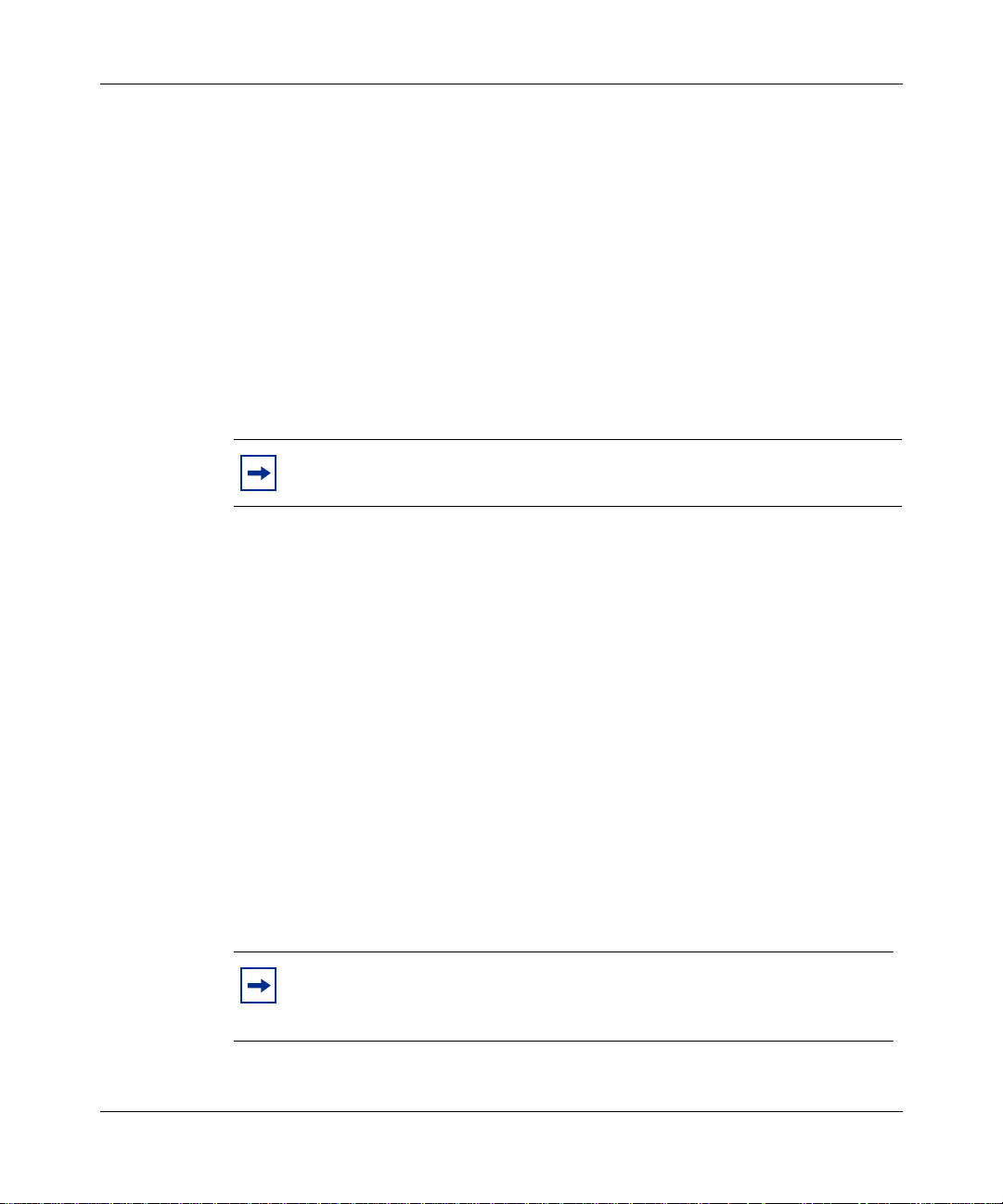
The Palette lists templates by product group (Figure 1).
Figure 1 Stack and Switch Palette templates
Chapter 1 Configuring switches 23
Note:
data, see Using the Optivity Quick2Config 2.2 Client Software.
To learn how to use Quick2Config to add switch configuration
Configuring Business Policy Switches with Optivity Quick2Config
Page 24
24 Chapter 1 Configuring switches
When you create standal one and st ack templa tes, Quick 2Conf ig cr eates def ault IP,
MLT, SNMP, STP, and QoS (Business Policy Switch 2000 only) configuration
objects in the navigation pane tree. Standalone switches also automatically
include configuration objects for switch ports and a default port-based VLAN.
Note:
them from th e Palette.
To match the actual configuration of the device you are creating, you can use the
Palette to add the following configuration objects to a standalone or stack system:
• 1 to 8 stack units (each in cl udes swit ch port s and a def aul t, port-b ased VLAN)
• Media-dependent adapter (MDA) hardware
• VLANs
• Internet Gateway Management Protocol (IGMP)
You cannot delete these default configuration objects, or create
Adding or changing system information
This section describes how to use Quick2Config to initially configure a switch
that you created from the Configuration Data Palette, or to modify the imported
system information for a managed switch.
Note:
in an imported configuration.
In most cases, you do not have to modify the system information
311208-A Rev 00
You can configure several system properties:
• To set or change the system name, contact, or location information, see
“Configuring basic properties,” next.
• To enable or disable Ethernet switch and MD A ports , or to conf i gure Eth ernet
line speed, see “Configuring Ether net ports” on page 26.
• To enable or disable ATM switch and MDA ports on a BayStack swit ch, or to
configure the p ort ATM properties , see “Configuring ATM MDA ports
(BayStack 450 only)” on page 27.
Page 25
Chapter 1 Configuring switches 25
• To set or change the switch IP address or subnet mask, see “Configuring IP”
on page 30.
• To supply the required SNMP community strings or to enable SNMP traps,
see “Configuring SNMP” on page 31.
Configuring basic properties
When you import a switch, some general system information is added to the
database. You can view or configure the system name, contact, and location
strings for a switch.
To modify the basic system properties for a switch:
1
In the navigation pane, select the switch.
2
In the context-sensitive pane, click the Properties tab.
3
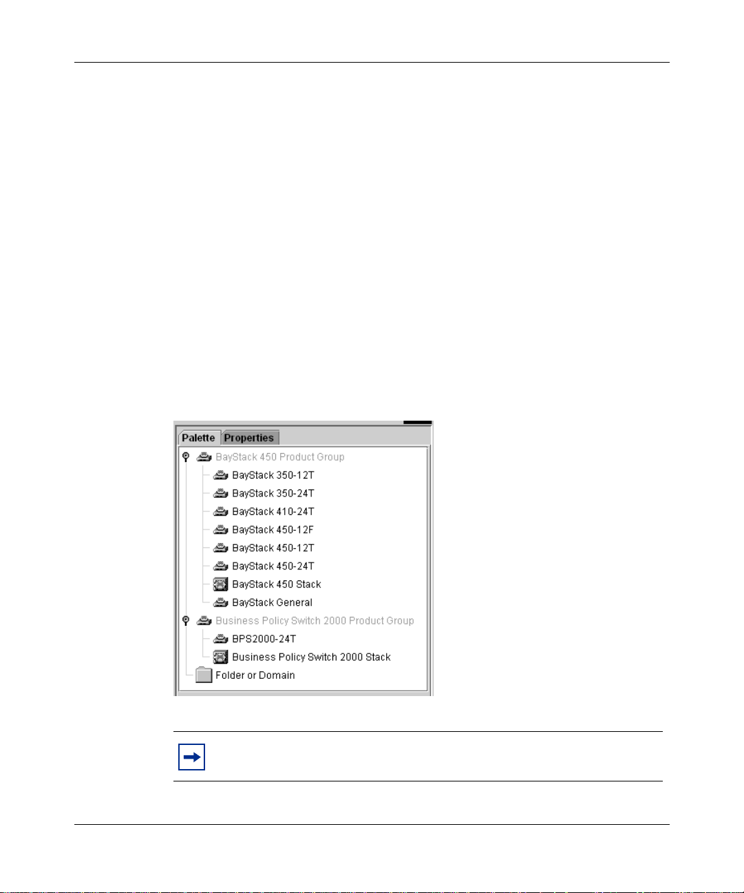
Click the Basic tab (Figure 2).
Figure 2 Basic tab system properties
4
In the System Contact, System Location, and System Name fields, enter
ASCII strings to identify the switch.
Each string can be up to 56 characters.
Quick2Config queries the system management information base (MIB) to report
the hardware, firmware, and software versions running on the switch, and the
length of time since the last reset. You cannot edit these fields.
Configuring Business Policy Switches with Optivity Quick2Config
Page 26
26 Chapter 1 Configuring switches
Configuring Ethernet ports
You can use Quick2Config to enable or disable switch and MDA ports, and to set
the port speed for an Ethernet port.
To set basic Ethernet port properties:
1
In the navi gati on pane , open t he swit ch or Eth ernet MDA and select a port. To
assign the same properties to a group of ports on the same switch, select
multiple ports in the navigation pane.
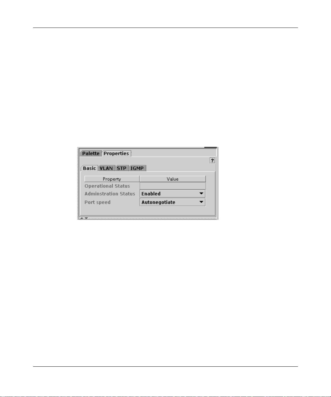
The port Basic tab opens in the context-sensitive pane (Figure 3).
Figure 3 Basic port properties
311208-A Rev 00
The Operational Status field indicates the current link state of the port, as
follows:
• Up indicates that the port is connected and operational.
• Down indicates that the port is not connected or is not operational.
The field is blank when you ar e working offl i ne to cre ate a new configurat i on.
2
From the Administration Status list, choose Enabled or Disabled to force the
link up or down.
3
From the Port speed list, choose the Ethernet line speed and duplex mode
combinations for the selected port; or, choose Autonegotiate to configure the
port to match the best service provided by the connected station, up to
100 Mb/s Full Duplex.
Valid options depend on the MDA hardware. Fiber optic links do not use
autonegotiation.
Page 27

Chapter 1 Configuring switches 27
Full duplex operation is intended for directly connected links, such as
between two switches or between a switch and an end station. Half duplex
operation, where transmission occurs in one direction at a time, is usually the
best choice for share d links that re quire ac cess contr ol and collisi on detecti on.
Note the foll owing:
• You can set gigabit MDA ports to Autonegotiate or 1000 Mb/s Full
Duplex only.
• Business Polic y Switch 2000 fiber optic ports sup port onl y 100 Mb/s Full
Duplex.
• BayStack 450 fiber optic ports support 100 Mb/s Half Duplex or
100 Mb/s Full Duplex.
You can also set the following additional properties at the port level:
• VLAN port properties — see “Configuring VLAN ports” on page 42
• Spanning tree protocol (STP) port properties — see “Configuring spanning
tree” on page 55
• Internet Group Management Protocol (IGMP) static router port property —
see “Creating static router ports” on page 49
Configuring ATM MDA ports (BayStack 450 only)
On BayStack 450 switches running agent version 3.1 or later, you can use
Quick2Config to configure the ATM ports on 2M3 and 2S3 MDA modules to
participate in an emulated LAN (ELAN).
Using ATM Forum LAN emulation (LANE), the BayStack 450 switch can
communicate transparently with ATM servers and other LAN clients. As LAN
emulation clients (LECs), the MDA ports perform data forwarding, address
resolution, and ATM control functions. A LAN Emulation server (LES) in the
network provides MAC-to-ATM address translation for the LECs.
Configuring Business Policy Switches with Optivity Quick2Config
Page 28
28 Chapter 1 Configuring switches
This section describes how to use the Basic properties tab to enable or disable
ATM ports, set the port speed, enable or disable the LEC software, and to
configure LEC failover.
To view or set basic ATM port properties:
1
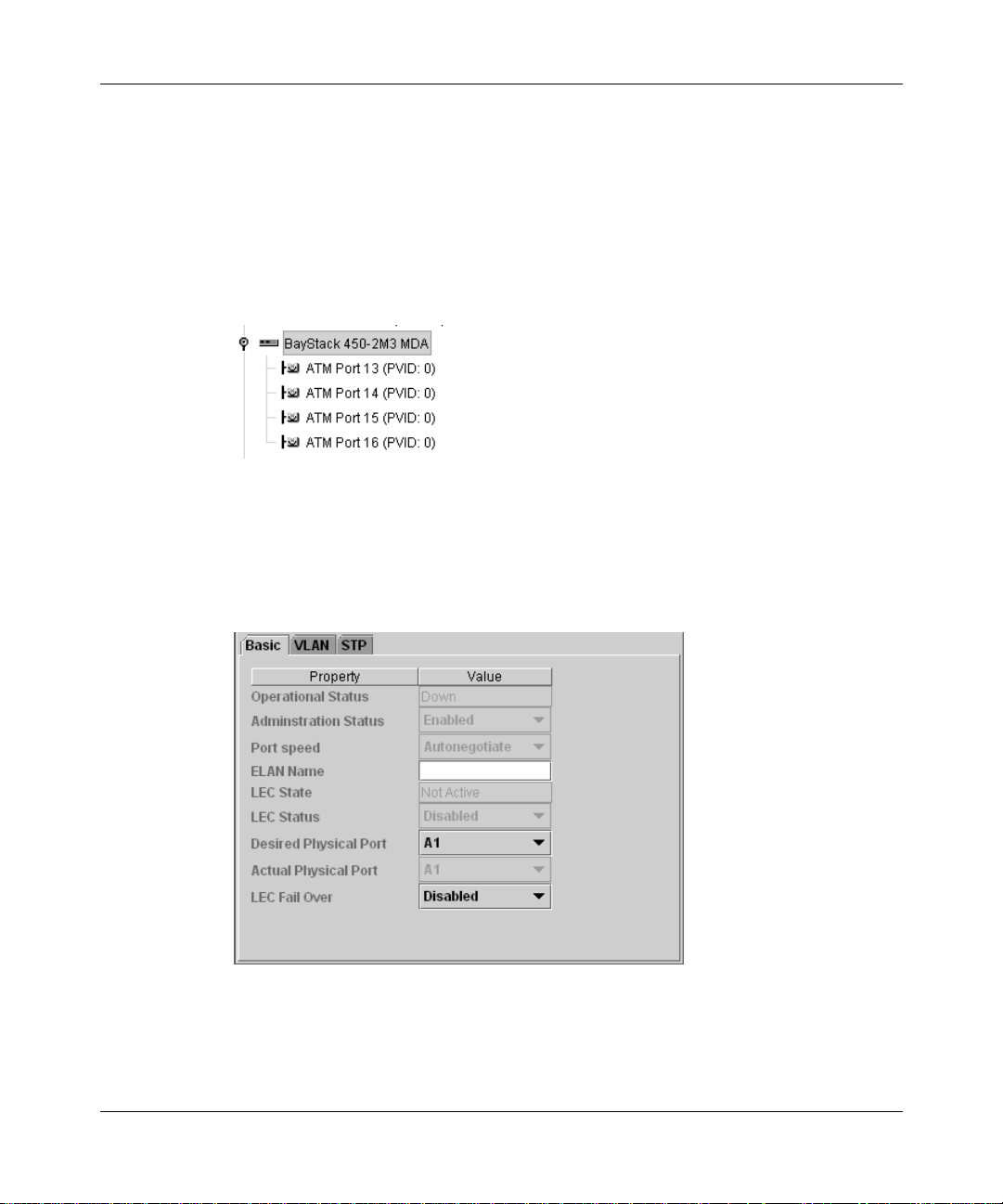
In the navigation pane, open the MDA and select a port (Figure 4).
Figure 4 ATM MDA ports
To assign the same properties to a group of ports, select multiple ports in the
navigation pane.
The port Basic tab opens in the context-sensitive pane (Figure 5).
Figure 5 ATM port properties
311208-A Rev 00
Page 29

Chapter 1 Configuring switches 29
The Operational Status property indicates the current link state of the port, as
follows:
• Up indicates that the port is connected and operational.
• Down indicates that the port is not connected or is not operational.
The LEC State field indicates whether the LAN emulation client is currently
active.
2
From the Administration Status list, choose Enabled.
3
From the Port speed list, choose a line speed and duple x mode for the selected
port, or choose Autonegotiate to match the best service available.
4
In the ELAN Name field, type the name of the ELAN.
5
To configure LEC Failover, see “Configuring LEC failover,” next.
You can also set VLAN and STP properties for each ATM port. For information,
see:
• “Configuring VLAN ports” on page 42
• “Configuring spanning tree” on page 55
Configuring LEC failover
LEC Failover allows ELAN traffic to move from a failing port to another available
port. A unique ATM address identifies each LEC, which the LANE protocol
associates with one or more port MAC addresses, or LEC instances.
To configure LEC fail over:
1
From the LEC Status list, choose Disabled.
You must disable the LEC before you can modify the failover properties.
2
From the Actual Ph ysica l Port lis t, cho ose A1 or A2 to id entif y the port that is
currently carrying traffic.
3
From the Desired Physical Port list, choose the alternate port to use in a
failover.
For example, if the Actual Physical Port is A1, choose A2.
4
From the LEC Fail Over list, choose Enabled.
Configuring Business Policy Switches with Optivity Quick2Config
Page 30

30 Chapter 1 Configuring switches
Configuring IP
You can use Quick2Config to conf igur e the subnet mas k and defau lt gate w ay for a
switch, and to view the switch MAC and IP addresses. The stack or standalone IP
and MAC addresses are imported from the device and are read-only.
To set IP properties:
1
In the navigation pane, open the switch object and select IP.
The IP Basic tab opens in the context-sensitive pane (Figure 6).
Figure 6 IP properties
311208-A Rev 00
2
Type the subnet mask for the IP address.
Network routers use the subnet mask to determine the network or subnet
address portion of a host’s IP address. The bits in the IP address that contain
the network address (including the subnet) are set to 1 in the address mask,
and the bits that contain the host identifier are set to 0.
3
Type the IP address of the default gateway host.
Page 31

Chapter 1 Configuring switches 31
Configuring SNMP
You can use Quick2Config to supply the required SNMP community strings for a
switch, and to enable SNMP traps.
Traps are SNMP management information packets generated by devices on the
network. You can configure 1 to 4 management stations as trap receivers, to
receive all SNMP trap messages from the selected switch.
To set the SNMP properties for a switch:
1
In the navigation pane, open the switch and select the SNMP object.
The SNMP Basic tab opens in the context-sensitive pane (Figure 7).
Figure 7 SNMP properties
2
For in-band SNMP operations, type the ASCII string of the read/write and
read-only community strings that are currently set for the switch.
Note:
You must specify the correct community strings in order to
communicate with the switch. You cannot use Quick2Conf ig to cha nge a
community string.
Configuring Business Policy Switches with Optivity Quick2Config
Page 32

32 Chapter 1 Configuring switches
3
To configure SNMP trap receivers for the switch, enter the IP address and
community string for one to four trap receivers in the Trap Receivers table.
a
To add a new trap receiver to the table, click the green plus sign (+).
b
Type the IP address and community string of each trap receiver you want
to specify.
4
If you want the switch to send a trap wh en there is an SNMP authe ntication
failure, enable the Authentication Trap property.
Exporting configurations
Business Policy Switch 2000 devices use SNMP to transfer configuration data;
they do not supp ort TFTP. For export procedures, see Using the Quick2Conf ig 2.2
Client Software.
Note:
File menu is not disabled, this option does not work for Business Policy
Switch 2000 and BayStack switches.
When you export a configuration, Quick2Config sends SNMP set requests to the
switch, updating the switch properties that you modified. Before exporting
configuration data, Quick2Config verifies that the following information in the
exported configuration data matches the information on the target switch:
• Device IP address
• Community string
• Model number and type of switch
• Units in a st ack
• MDA hardware
Although the Export > From TFTP option on the Quick2Config
311208-A Rev 00
Page 33

Chapter 1 Configuring switches 33
Quick2Config also validates the following VLAN con figuration data:
• Port VLAN identifier (PVID) values — Each PVID must match a VLAN ID
configured on the same device.
• VLAN names — The VLAN name property must n ot be emp ty, duplicated, or
more than 16 characters.
If one of the ver ifications f ail s, the export proces s stops immediately and dis pla ys
an error message.
Configuring Business Policy Switches with Optivity Quick2Config
Page 34

Page 35

Chapter 2
Configuring VLANs
You use virtual local area netw orks (VLANs) t o create scala ble broadcast domains
in your network.
Read the sections of this chapter to learn how to use Optivity Quick2Config 2.2 to
configure Business Policy Switch 2000 and BayStack devices in one or more
VLAN:
• “About VLAN services,” next
• “Creating VLANs” on page 38
About VLAN services
35
When you add a Business Policy Switch 2000 or BayStack device to the
Configuration Data folder, Quick2Config automatically creates a default
port-based VLAN (VLAN ID 1) that is configured with all ports on the device.
On each switch, you can modify the default VLAN, and create as many as 63
additional VLANs.
This section includes the following topics about VLAN services on Business
Policy Switch 2000 devices:
• “VLAN types” on page 36
• “802.1Q frame tagging” on page 37
• “VLAN learning modes” on page 37
Configuring Business Policy Switches with Optivity Quick2Config
Page 36

36 Chapter 2 Configuring VLANs
VLAN types
The criteri a used to determine member ship in a VLAN determines the VLAN
type. Table 1 describes the types of VLAN you can build with Quick2Config. All
VLANs are defined by IEEE 802.1d. Business Policy Switch 2000 devices
support all three types. The BayStack 450 pr oduc t fa mily suppo rts por t-bas ed and
protocol-based VLANs.
Table 1 VLAN types
Type
Port Destination
MAC
Protocol Protocol
1 If they are in the same bridge group on a single device, ports in the same VLAN can communicate
using IEEE 802.1Q level 2 switching.
2 The switch supports up to 48 MAC-based VLANs.
Membership
based on
MAC address
(switch port
address)
2
Source MAC
address
(network
adapter
address)
header
IEEE 802.1d
standard
Layer 1
Layer 2 Use to enforce a MAC-level security scheme
Layer 2 You can configure a single port in multiple
Advantages/disadvantages
1
Forwards packets within a single network, but
requires routers to forward the packets between
port VLANs and to other networks.
Can be added easily to an existing network
topology. The main disadvantage is that if the
ports used by VLAN members change,
reconfiguration is required.
that differentiates groups of users.
Configured devices may be freely relocated
without having to reconfigure them. The main
disadvan tage is that this type is diff icult to set up
in large existing networks.
protocol-based VLANs; one for each protocol
type. A good choice in heterogeneous networks
where the devices to be added to VLANs are
already segmented by protocol. The main
disadvantage is that this type restricts VLAN
membership.
311208-A Rev 00
In a typical network, a switched port that belongs to one or more protocol-based
VLANs also belongs to a port-based VLAN. The protocol-based VLAN defines
the broadcast domain for packets that can be classified by protocol type. The
port-based VLAN defines the broadcast domain for all other types of packets.
Page 37

Chapter 2 Configuring VLANs 37
802.1Q frame tagging
Business Policy Switch 2000 devic es operate in accordanc e with the IEEE 802.1Q
tagging rules. The 802.1Q specification defines a method to coordinate VLANs
across multiple switches. A tagged port inserts an additional 4-octet header (tag)
in each frame, after the source MAC address and before the frame type.
The switches that route VLAN fram es are VLAN-aware, whereas devices that
receive the frames (user workstations and pr inters, for example) may be
VLAN-unaware. This distinction is the basis for the two types of VLAN
connections:
• Trunk links (or tagged links) connect VLAN devices that are VLAN-aware
(the switches that per form routing, for exampl e). A frame transmi tted across a
trunk link is explicitly tagged with a 802.1Q VLAN header tag. The routing
device gets the destination of a tagged VLAN frame by consulting a filtering
database. You can configure VLAN trunk links to filter tagged frames,
untagged frames, or both.
• Access links (or untagged links) connect a VLAN-aware device to a
VLAN-unaware device. Frames transmitted across an access link do not
include VLAN headers. By default, all ports are configured as access links,
untagged members of the default VLAN (VLAN #1).
VLAN learning modes
The 802.1Q specification defines two ways that VLAN devices store MAC
addresses in their bridging tables:
• Independent VLAN learning (IVL) — allows the same MAC address to
appear in different broadcast domains. An IVL-capable device maintains
independent bridge tables for each VLAN, allowing devices to reuse a MAC
address in different VLANs.
• Shared VLAN learning (SVL) — constrains a MAC address to only one
VLAN. SVL-based devices build a giant bridge table, but allow a MAC
address to appear only once in the table, regardless of how many VLANs
exist.
Business Policy Switch 2000 and BayStack switches can support either method.
When you configure the VLAN, you indicate which learning mode to use.
Configuring Business Policy Switches with Optivity Quick2Config
Page 38

38 Chapter 2 Configuring VLANs
Creating VLANs
Before you can build a VLAN using Optivity Quick2Config 2.2, you must install
and initially configure the network devices. For information about importing
switch configurations, see “Importing configurations” on page 22.
The following summarizes the steps to create and configure a VLAN:
Note:
1
Use the Quick2Config Palette to add a VLAN to the switch.
2
Assign the VLAN ID and name.
3
Configure additional VLAN properties. How you configure the VLAN
depends on the VLAN type:
• Port-based VLAN (next)
• Protocol-based VLAN (page 39)
• MAC-based VLAN (page 41)
4
Assign VLAN ports.
5
Optionally, configure IGMP snooping. For information, see Chapter 3,
“Configuring IGMP snooping.”
6
Export configuration data to the switches on the network.
For detailed procedures, see the sections that follow.
Configuring a port-based VLAN
For each switch that participates in the VLAN:
311208-A Rev 00
1
Create the VLAN from the Palette.
a
In the navigation pane, open each participating switch and select the
VLAN.
b
In the context-sensitive pane, click the Properties tab.
c
Add a port-based VLAN to the participating switches.
2
In the navigation pane, select the VLAN.
Page 39

Chapter 2 Configuring VLANs 39
3
In the context-sensitive pane, click the Properties tab (Figure 8).
Figure 8 Port-based VLAN
4
In the Basic tab, assign the VLAN ID and name.
a
Keep the default VLAN ID 1, or specify a VLAN ID of 2 to 64. The ID
must be identical in each participating switch. By coordinating VLAN
IDs, you can extend a VLAN to multiple switches.
b
T y pe a descr ipti v e VLAN name, 1 to 16 characte rs, to ide ntify th e VLAN.
The name must be unique, and identical in each participating switch.
5
In the IVL/SVL list, choose independent VLAN learning (IVL) or shared
VLAN learning (SVL) bridging tables for this VLAN.
For information, see “VLAN learning modes” on page 37.
6
Configure the participating ports.
See “Configuring VLAN ports” on page 42.
Configuring a protocol-based VLAN
For each switch that participates in the VLAN:
1
Create the VLAN from the Palette.
a
In the navigation pane, select the switches that will participate in the
VLAN.
b
In the context-sensitive pane, open the VLANs folder in the Palette tab.
c
Add a protocol-based VLAN to the participating switches.
Configuring Business Policy Switches with Optivity Quick2Config
Page 40

40 Chapter 2 Configuring VLANs
2
In the navigation pane, select the VLAN.
3
In the context-sensitive pane, click the Properties tab (Figure 9).
Figure 9 Protocol-based VLAN properties
4
Assign the VLAN ID and name.
a
Keep the default VLAN ID 1, or specify a VLAN ID of 2 to 64. The ID
must be identical in each participating switch.
b
T y pe a descr ipti v e VLAN name, 1 to 16 characte rs, to ide ntify th e VLAN.
The name must be unique, and identical in each participating switch.
5
In the IVL/SVL list, choose whether the switch should use independent
VLAN learning (IVL) or shared VLAN learning (SVL) bridging tables for
this VLAN.
For information, see “VLAN learning modes” on page 37.
6
In the Protocol table, ch oose a predef i ned protocol , or choose Use r- Defi ned to
specify a protocol not listed.
If you choose User -Def ined, typ e an IETF RFC 1 356 protocol i dentif ier (PID)
in the User defined PID field.
7
Configure the ports to participate in the VLAN. See “Configuring VLAN
ports” on page 42.
311208-A Rev 00
Page 41

Chapter 2 Configuring VLANs 41
Configuring a MAC SA-based VLAN
You can configure up to 48 MAC SA-based VLANs on a switch.
In a VLAN based on the MAC source address (SA), a frame is associated with a
VLAN only if the source MAC address is on an explicit list of MAC addresses
that comprise the VLAN. Because it is necessary to explicitly associate MAC
addresses with a MAC SA-based VLAN, the administrative overhead can be high.
To configure a MAC SA-based VLAN, complete these steps for each switch that
participates in the VLAN:
1
Create the VLAN from the Palette.
a
In the navigation pane, select the switches that will participate in the
VLAN.
b
In the context-sensitive pane, open the VLANs folder in the Palette tab.
c
Add the desired type of V LAN to the participating switches.
2
In the navigation pane, select the VLAN.
3
In the context-sensitive pane, click the Properties tab (Figure 10).
Figure 10 MAC-based VLAN properties
4
In the IVL/SVL list, choose whether the switch should use independent
VLAN learning (IVL) or shared VLAN learning (SVL) bridging tables for
this VLAN.
For information, see “VLAN learning modes” on page 37.
Configuring Business Policy Switches with Optivity Quick2Config
Page 42

42 Chapter 2 Configuring VLANs
5
In the MAC Addresses field, click Edit.
The MAC Addresses window opens.
6
Specify MAC addresses, one line at a time.
Use the following format:
aa:bb:cc:dd:00:11
Note:
You can cut and paste MAC addresses from a text, word
processing, or speadsheet file.
7
Configure the ports to participate in the VLAN. See “Configuring VLAN
ports,” next.
Configuring VLAN ports
To assign switch ports to participate in a VLAN:
1
In the navigation pane, select the switch ports.
As you select VLAN ports, note the following:
• A switch port can be an ingress member of only one port-based VLAN.
• No port can be a member of more than one protocol-based VLAN with
the same protocol.
• A tagged port can have two protocol-based VLANs of the same protocol
type.
2
Create shortcuts from the ports to the VLAN.
a
Right-click the selected ports, then choose Copy.
311208-A Rev 00
b
In the navigation pane, select the VLAN.
c
Right-click, then choose Paste as Shortcut.
To configure VLAN ports:
1
In the navigation pane, select the VLAN ports.
You can set properties on individual ports, or configure groups together.
Page 43

Chapter 2 Configuring VLANs 43
2
In the context-sensitive pane, click the Properties tab.
3
Click the VLAN tab (Figure 11).
Figure 11 Port VLAN tab
By default, all ports are configured as access ports with Priority 0.
4
From the Port Type list, choose Trunk.
For information about access and trunk connections, see “802.1Q frame
tagging” on page 37.
The port icon changes, so you can differentiate trunk and access ports in the
navigation pane.
5
In the PVID field, match the VLAN ID number.
6
In the Port Priority field, typ e or choose an 802.1p user priority value for this
port. By default, all ports have priority 0.
Note:
To see how how the 802.1p user priorities map to standard
Nortel Networks IP class of service values, refer to Table 13 on page 82.
7
Configure how the port filters 802.1Q tagged frames.
In the Filter field, check Tagged frames to dropped frames with the 802.1Q
tag, or check Untagged to drop frames that do not have the tag. To disregard
frame tagging, clear both check boxes. To discard all frames on this port,
check both.
Configuring Business Policy Switches with Optivity Quick2Config
Page 44

Page 45

Chapter 3
Configuring IGMP snooping
You can use Internet Group Management Protocol (IGMP) snooping to conserve
bandwidth and control IP multicast st reams.
Read the sections of this chapter to learn how to use Optivity Quick2Config 2.2 to
configure IGMP snooping:
• “About IP multicast and IGMP,” next
• “IGMP snooping configuration rules” on page 47
• “Enabling IGMP snooping” on page 47
• “Creating static router ports” on page 49
About IP multicast and IGMP
45
IP hosts use I GMP and I P mul ti ca st ad dressing to report their group memberships
to immediate neighboring multicast routers. Routers send IGMP queries to all
hosts, and IGMP hosts respond by sending IGMP reports to the multicast address
of the grou p they want to participate in.
The switch uses the information learned from IGMP activity to map IP multicast
groups to switch ports. Packets destined to a particular multicast group are
delivered only to those member ports.
Note:
group are neither IGMP routers nor IGMP hosts. The IGMP snooping
feature optimizes IP multicast in a bridged Ethernet environment.
The Business Policy Switch 2000 and BayStack 450 prod uct
Configuring Business Policy Switches with Optivity Quick2Config
Page 46

46 Chapter 3 Configuring IGMP snooping
IGMP host membership reports
IP multicast router s use IGMP t o learn a bout the e xi stenc e of h ost gr oup me mbers
on their directly at tache d subnets . The IP m ulti cast ro uters get th is info rmatio n b y
broadcasting IGMP queries and listening for IP hosts reporting their host group
memberships. This process is used to set up a client/server relationship between
an IP multicast source that provides the data streams and the clients that want to
receive the data.
The client/server path is set up as follows:
1
The designated router sends out a host membership query to the subnet and
receives host membership reports from end stations on the subnet.
2
The designated routers set up a path between the IP multicast stream source
and the end stations.
3
Periodically, the router continues to query end statio ns on whether to con tinue
participation.
4
As long as any client continues to participate, all clients, including
nonparticipating end stations on that subnet, receive the IP multicast stream.
Note:
stream, IP multicast traffic still consumes bandwidth on the subnet.
IGMP snooping
The IGMP snooping feature provides the same bene fit as IP multicast rout er s, but
in the local area.
With IGMP snooping enabled, a switch senses IGMP host membership reports
from attached stations and uses this information to set up a dedicated path
between the requesting station and a local IP multicast router. After the pat h is
established, the switch blocks the IP multicast stream from exiting any other port
that does not connect to another host member, thus conserving bandwidth.
Even if nonparticipating end stations filter the IP multicast
311208-A Rev 00
Page 47

Chapter 3 Configuring IGMP snooping 47
Proxy reports
IGMP snooping allows the switch to send multicast data to the members of a
multicast group in a given VLAN only. When a switch acts as IGMP proxy, it
forwards only one report to the router instead of one report for every member of
the multicast group.
IGMP snooping configuration rules
Consider the following to determine how IGMP snooping affects a network
topology:
• Static router ports must be port members of at least one VLAN.
• If you configure an SVL VLAN port as a static router port, is configured as a
static router por t for all VLANs on t hat por t. If you re mo v e a stat ic ro uter p ort
from an SVL VLAN, the port is removed as a member of all of its co nfigured
VLANs. The IGMP configuration of IVL VLANs is not propagated to all
VLANs on the port.
• You cannot configure a port that is configured for port mirroring as a static
router port, and you cannot configure a static router port for port mirroring.
• If you configure a mu ltil ink tr unk (MLT) member as a static router port, al l of
the MLT members are configured as stati c rou te r por ts. If you remove a stat ic
router port that is an MLT member , all memb ers are a utoma tica lly r emo v ed as
static router port members.
• The IGMP snooping feature is not dependent on the Spanning Tree Protocol.
• The IGMP snooping feature is not dependent on rate limiting.
Enabling IGMP snooping
To enable IGMP snooping and configure IGMP properties on a VLAN:
1
In the navigation pane, select the VLAN.
2
In the context-sensitive pane, click Properties.
Configuring Business Policy Switches with Optivity Quick2Config
Page 48

48 Chapter 3 Configuring IGMP snooping
3
Click the IGMP tab (Figure 12).
Figure 12 IGMP properties
4
From the IGMP Snooping list, choose Enabled.
Enabling IGMP Snooping on an SVL VLAN enables the feature on all
VLANs configured for the switch.
5
If you want th is switch to c onsolidate th e IGMP host membership reports it
receives on downstream ports before forwarding, choose Enabled from the
Proxy list.
Enabling Proxy on an SVL VLAN enables consolidated proxy reports on all
VLANs in the switch.
6
If packet losses on a subnet are unacceptably high, increase the Robust Value
to offset the expected packet loss.
From the Robust Value list, choose a value between 1 and 64.
7
To change the frequency of IGMP queries allowed in this subnet from the IP
multicast router, change the default Query Time value of 125 seconds.
From the Query Time list, choose a value betwen 1 and 512 seconds.
8
Configure one or more static router ports from the VLAN to an IP multicast
router. See “Creating static router ports,” next.
311208-A Rev 00
Page 49

Creating static router ports
With IGMP snoop ing enabl ed, determine which VLAN ports have a path to an IP
multicast router, then configure those links as static router ports.
To configure a switch port as an IGMP static router port:
1
In the navigation pane, select one or more VLAN ports with a path to a
multicast router. It is not necessary for the path to be direct.
2
In the context-sensitive pane, click the Properties tab.
3
Click the IGMP tab (Figure 13).
Figure 13 Port IGMP tab
Chapter 3 Configuring IGMP snooping 49
4
Check Static Router Port.
If the port is a member of an MLT group, all MLT members become IGMP
static router ports.
Configuring Business Policy Switches with Optivity Quick2Config
Page 50

Page 51

Chapter 4
Configuring multilink trunks
You can use multilink trunks (MLTs) to combine Ethern et ports in a sin gle, logi cal
connection.
Read the sections of this chapter to learn how to use Optivity Quick2Config 2.2 to
configure MLTs:
• “About multilink trunking,” next
• “MLT configuration guidelines” on page 52
• “Creating an MLT group” on page 53
About multilink trunking
51
In an MLT group, 2 to 4 ports form a single link to another switch or server. In
full-duplex mode, the aggregate throughput between the two devices can increase
up to 800 Mb/s. MLT software detects misconfigured or broken trunk links and
redirects traffic on the link to other members within the trunk group.
You can configure trunk members within a s ing le unit, within any of the units in a
stack configuration, or distribute trunk members between stacks (distributed
trunking).
To learn more about the ports you can configure in an MLT group, see “MLT
configuration guidelines” on page 52.
Configuring Business Policy Switches with Optivity Quick2Config
Page 52

52 Chapter 4 Configuring multilink trunks
MLT configuration guidelines
You can configure up to 6 MLT groups on each switch or stack. The Spanning
Tree Protocol considers an MLT to be a single port.
To plan for each MLT:
• Determine which switch ports to combine as trunk members.
Choose a minimum of 2 and a maximum of 4 Ethernet ports for each trunk.
Make sure that the ports you choose are:
— Enabled
— Not probe ports
— Not members of another MLT
— Members of the same VLAN, if they are VLAN participants
On the trunk member ports, the following properties must have same values:
— Port speed
— VLAN port type
— STP participation
— IGMP static router
311208-A Rev 00
Note:
frames, all of the MLT group members are automatically configured for
802.1q frame tagging.
• Consider how existing VLANs will be affected by the addition of each trunk.
See “Configuring VLANs” on page 35.
• Consider ho w the e xi stin g spanni ng tr ee will reac t to the trunk conf i gurati ons.
See “Configuring spanning tree” on page 55.
• To avoid errors, make sure that all network cabling is complete and stable
before you export a new trunk configuration.
If you configure an MLT member to filter tagged or untagged
Page 53

Creating an MLT group
To configure 2 to 4 switch ports in an MLT group:
1
In the navigation pane, open a switch and select the ports.
For information about the ports you can configure in an MLT group, see
“MLT configuration guidelines” on page 52.
2
Open the MLT Group folder.
3
Create shortcuts from the ports to the MLT.
There are 6 MLT templates in the MLT Group folder. Use any unconfigured
MLT.
a
Right-click the selected ports, then choose Copy.
b
In the navigation pane, select the MLT.
c
Right-click, then choose Paste as Shortcut.
4
In the navigation pane, select the MLT.
Chapter 4 Configuring multilink trunks 53
5
In the context-sensitive pane, click the Properties tab (Figure 14).
Figure 14 MLT properties
6
In the Name field, type a descriptive name to identify the trunk.
7
From the Status list, choose Enabled.
Configuring Business Policy Switches with Optivity Quick2Config
Page 54

Page 55

Chapter 5
Configuring spanni ng tree
By default, all switch ports are enabled for participation in the Spanning Tree
Protocol (STP).
Read the sections of this is chapter to learn how to use Quick2Config to disable
STP on individual ports or MLT trunks, view STP group and port values, and
customize STP group properties:
• “About the Spanning Tree Protocol,” next
• “Configuring STP ports” on page 55
• “Viewing and configuring STP group properties” on page 58
About the Spanning Tree Protocol
55
The Spanning T ree Prot ocol, def ined in t he IEEE 802.1D sta ndard, deter mines the
best path between segments of a bridged network. When multiple paths exist, the
spanning tree a lgorithm conf igures the netw ork to use o nly the most ef f ici ent path.
If the selected path fails, STP automatically reco nfigures the network to make
another path active and sustain network operation.
Configuring STP ports
By default, all switch ports participate in the spanning tree algorithm. For each
switch port or MLT group, you can:
• Change the STP learning state
• Disable STP participation
Configuring Business Policy Switches with Optivity Quick2Config
Page 56

56 Chapter 5 Configuring spanning tree
Changing the STP learning state
To change the learning state:
1
In the navigation pane, select one or more switches or MDA ports.
Select only ports that do not currently belong to an existing STP group.
2
In the context-sensitive pane, click the Properties tab.
3
Click the STP tab (Figure 15).
Figure 15 STP port properties
311208-A Rev 00
4
From the Participation list, choose a learning state for this port or change the
state to Forwarding only.
By default, all ports are configured for Normal Learning. Fast Learning
reduces the state transition timer to 2 seconds.
Page 57

Chapter 5 Configuring spanning tree 57
In the remaining fields, Quick2Config reports the read-only values of STP port
properties (Table 2).
Table 2 STP port read-only properties
Property Description
Priority Indicates the STP priority for this port. Port priority determines the root
Path Cost STP uses the path cost o f each port to determine the most efficent p ath to
State Indicates the current port state within the spanning tree network:
bridge. A lower number establishes a higher priority. When one or more
ports have the same path cost, the spanning tree algorithm selects the
path with the highest priority (lowest numerical value).
the root bridge. The higher the LAN speed, the lower the path cost. Path
Cost = 1000/LAN speed (i n M b/s). Th e default v a lue is 1 for gigabit ports,
10 for 100 Mb/s ports, and 100 for 10 Mb/s ports.
Disabled, Blocking, Listening, Learning, Forwarding.
STP ports transition to various states, as determined by the Participation
property. When you disable Participation, the port transitions only to the
Forwarding state. When the Participation is enabled, the port transitions
through the Blocking, Listening, and Learning states before entering the
Forwarding state. The default value is dependent on topology.
Disabling STP port participation
When you disable STP participation, the port does not participate in the spanning
tree algorithm and transitions to the Forwarding state.
To disable a port or MLT group from spanning tree participation:
1
In the navigation pane, select one or more switch or MDA ports.
Select only ports that do not currently belong to an existing STP group.
2
In the context-sensitive pane, click the Properties tab.
3
Click the STP tab (Figure 15).
4
From the Participation list, choose Disabled.
Configuring Business Policy Switches with Optivity Quick2Config
Page 58

58 Chapter 5 Configuring spanning tree
Viewing and configuring STP group properties
To configure a spanning tree group (STG):
1
In the navigation pane, open the Spanning Tree Protocol Group folder.
2
Select the STG ID.
The STP Basic tab opens (Figure 16).
Figure 16 Spanning Tree Protocol Group tab
Table 3 describes the STP group properties. You can customize the value of
Bridge Priority, Bridge Hello Time, Bridge Maximimum Age Time, and Bridge
Forward Delay.
Table 3 Spanning Tree Protocol Group properties
Parameter Description Action
ID Identification number for this STG. Read-only value
Designated Root The bridge ID of the root bridge, as determined by the spannin g tree
algorithm.
Root Port The switch port number that offers the lowest path cost to the root
bridge.
311208-A Rev 00
Read-only value
Read-only value
Page 59

Chapter 5 Configuring spanning tree 59
Table 3 Spanning Tree Protocol Group properties (continued)
Parameter Description Action
Root Path Cost The path cost from this switch port to the root bridge. Read-only value
Hello Time The Actual Hello Interval , the am ount of t ime betw een tr ansmiss ions
of configuration Bridge Protocol Data Units (BPDUs) that the root
bridge is currently us ing.
All bridges participating in the spanning tree network use the root
bridge’s Hello Interval parameter value. See also Bridge Hello Time.
Maximum Age
Time
Forward Delay The Forward Delay parameter value that the root bridge is currently
Bridge Priority The management-assigned priority value of the bridge ID in
Bridge Hello
Time
Bridge Maximum
Age Time
The Maximum Age Time parameter value that the root bridge is
currently using. This value specifies the maximum age that a Hello
message can attain before it is discarded.
The root bridge’s Maximum Age Time parameter value becomes the
actual Maximum Age Time parameter value for all bridges
participating in the spanning tree network. See also Bridge
Maximum Age Time.
using. This value specifies the amount of time that the bridge ports
remain in the Listening and Learning states before entering the
Forwarding state.
The root bridge’s Forward Delay parameter value becomes the
actual F orward Dela y p ar am eter value for all bridges participating i n
the spanning tree network. See also Bridge Forward Delay.
hexadecimal notation, which is the most significant byte of the
bridge ID . Th e STA uses this par amete r to determine the root bridge
(or designated bridge). For example, the bridge with the lowest
bridge ID becomes the root bridge, with Bridge Priority values
compared first, followed by the hardware addresses.
The Hello Interval (the amount of time between transmissions of
BPDUs) specified by management for this bridge. This property
takes effect only when this bridge becomes the root bridge.
Although you can set the Hello Interval for a bridge using bridge
management softw are, once the spannin g tree computatio n process
is complete, all bridges participating in the spanning tree network
use the root bridge’s Hello Interval parameter value. If any bridge
becomes the root bridge, its Hello Interval parameter value
becomes the Actual Hello Interval parameter value for all bridges
participating in the spanning tree network. See also Hello Time.
The maximum age that a Hello message can attain before it is
discarded. This par ameter, specified by management f or this b ridge,
takes effe ct only when the bridge becomes the root bridge.
If this bridge becomes the root bridge, its Maximum Age Time
parameter value becomes the Actual Maximum Age Time
parameter value for all bridges participating in the spanning tree
network. See also Maximum Age Time.
Read-only value
Read-only value
Read-only value
Type a value from
0 to 65535.
The default value
is 8000.
Choose a value
from 1 to 10
seconds, or keep
the defaul t value of
2 seconds.
Choose a value
from 6 to 40
seconds, or keep
the defaul t value of
20 seconds.
Configuring Business Policy Switches with Optivity Quick2Config
Page 60

60 Chapter 5 Configuring spanning tree
Table 3 Spanning Tree Protocol Group properties (continued)
Parameter Description Action
Bridge Forward
Delay
The Forward Delay parameter value specified by management for
this bridge. This parameter takes effect only when this bridge
becomes the root bridge.
The Forward Delay parameter value specifies the amount of time
that the bridge ports remain in the Listening and Learning states
before entering the Forwarding state.
All bridges participating in the spanning tree network use the root
bridge’s Forward Delay parameter value. See also Forward Delay.
Choose a value
from 4 to 30
seconds, or keep
the defaul t value of
15 seconds.
311208-A Rev 00
Page 61

Chapter 6
Configuring QoS filters
You configure quality of service (QoS) policy filters on a Business Policy Switch
to prioritize critical applications or sensitive traffic and to help tailor network
performance.
Read the sections of this chapter to learn how to use Optivity Quick2Config 2.2 to
enable, view, configure, or modify QoS policy filters:
• “About QoS policy filters,” next
• “Configuration summary” on page 63
• “Configuring dynamic QoS management” on page 65
• “Configuring policies locally” on page 69
• “Configuring Q oS interfaces” on page 78
• “User priority and DSCP mapping” on page 82
• “Viewing trans mit queue information” on page 84
• “Resetting QoS values in Quick2Config” on page 88
61
About QoS policy filters
A QoS policy is a set of rules that a netw o rk i nterface uses to ide n ti fy and process
particular network traffic patterns. When traffic has the same attributes as those
specified in a configured QoS policy filter, the policy instructs the interface to
perform a specified action.
The Business Policy Switch 2000 employs Differentiated Services (DiffServ) to
participate in policy-based network traffic control. DiffServ is a QoS architecture
developed by the Internet Engineering Task Force (IETF); it provides different
types of services to different IP traffic flows.
Configuring Business Policy Switches with Optivity Quick2Config
Page 62

62 Chapter 6 Configuring QoS filters
Most Business Polic y Switches obt ain QoS polic y informati on from a serv er in t he
network that runs QoS policy management software such as Optivity Policy
Services (OPS). The Op tivity policy server transfers DiffServ information to
policy client devices using the Common Open Policy Services (COPS) protocol.
To manage QoS policies on the switch rather than from a policy server, you must
work with many compon ents. Each f ilter inco rporates inter face, clas sifi cation, and
action defin it ion s. Us er pri or it y values, DiffServ codepoint (DSCP) mapp ing , an d
priority and DSCP queue assignments also affect QoS policies.
For more information, see “DiffServ architecture,” next, or “Configuration
summary” on page 63.
DiffServ architecture
The DiffServ QoS architec ture operates as follow s:
1
A QoS policy serv e r se nds p oli cy information to net w ork policy clients in t he
form of DiffServ filters.
311208-A Rev 00
For example, a host running Optivity Policy Services software operates as
policy server for Business Policy Switches in a policy-enabled network.
2
When packets arrive at a policy client interface, the switch classifies the
packets according to DiffServ classifications from the policy server.
Packet classifications select packets according to a particular content in the
packet header such as the source address, destination address, source port
number, destination port number, or incoming interface.
3
The interface directs classified packets to traffic conditioners for further
processing such as marking or dropping.
Marking is the process of setting the Differentiated Services (DS) field of the
packet to a particular value. Dropping is the process of discarding some or all
of the packets to comply with a traffic profile.
4
The interface applies forwarding actions, or per-hop behaviors, to the
conditioned packets. These actions include queuing and shaping functions.
Page 63

Chapter 6 Configuring QoS filters 63
DiffServ codepoints
DiffServ architecture relies on a spec ial enc odi ng of t h e first 6 bits of the DS b yt e
in the IP header—the Ipv4 Type of Service (ToS) byte or the Ipv6 Traffic Class
byte. These first 6 bits of the ToS or Traffic Class byte are called the DiffServ
codepoint (DSCP).
The DSCP signifies the quality of service that a flow of packets should receive
when handled by a policy-enabled network.
Note:
DSCP but are able to process 802.1Q packets, an IEEE 802.1p class of
service (CoS) user priority is added as packet are transmitted.
For packet pri ori tization in layer 2 switches that do not recognize
Configuration summary
The Business Policy Switch has predefined QoS role combinations for its
external, MDA, and cascade ports. Optionally, you can create custom role
combinations for the switch interfaces. See “Creating new role combinations” on
page 79.
On each switch, you implement DiffServ QoS policy management in static or
dynamic mode.
• With dynamic DiffServ management, a policy server in the network sends all
QoS policy information to the switch using the COPS protocol. You do not
manually configure QoS policies, but you must enable dynamic management
and configure COPS information for policy server connections.
• With static DiffServ management, the internal policy agent on the switch
manages all QoS information. You must manually configure the QoS policie s.
By default, the Business Policy Switch is set to static DiffServ management.
Configuring Business Policy Switches with Optivity Quick2Config
Page 64

64 Chapter 6 Configuring QoS filters
Dynamic DiffServ management
In a policy-enabled network that uses a centralized policy server, each client
device operates in dynamic mode. There can be a single policy server for each
DiffServ domain, but a hierarchy of policy clients within the domain.
To operate with a COPS policy server in dynamic mode, you need to:
• Choose dynamic DiffServ management in the QoS Properties tab. See
“Configuring dynamic QoS management” on page 65.
• Configure COPS information for policy server connections.
See “Configuring COPS connections” on page 67.
Static DiffServ management
By default, a Business Policy Switch manages its QoS policies locally, without a
centralized COPS server. With static management, each switch is a DiffServ
domain.
311208-A Rev 00
In static mode, you must create the packet classification and filter action
components of QoS filters before you can configure QoS policies. See
“Configuring policies locally” on page 69.
You can also change the DSCP-to-802.1p mapping for packets that are marked at
egress. See “User priority and DSCP mapping” on page 82.
Page 65

Chapter 6 Configuring QoS filters 65
Configuring dynamic QoS management
With dy namic Dif fServ management ena bled, a COPS polic y serv er manages QoS
policies on the switch.
Note:
switch manages all QoS operation and you must configure policies
locally. See “Configuring policies locally” on page 69.
To enable a Business Policy Switch 2000 as a QoS policy client:
1
In the navigation pane, expand the switch device tree.
2
Select QoS.
3
Click the Properties tab to view the QoS policy agent Basic properties
(Figure 17).
Figure 17 QoS policy agent Basic properties
With dynamic DiffServ management disabled (the default), th e
Configuring Business Policy Switches with Optivity Quick2Config
Page 66

66 Chapter 6 Configuring QoS filters
4
Use the information in Table 4 to configure property values.
Table 4 QoS policy agent properties
Property Description Action
Dynamic Management Determines whether QoS
QoS Policy Agent State The current status of the QoS
Reset QoS Policy Agent
State to Default
QoS Policy Agent Retry
Timer
filters are configured locally
(static management) or
dynamically, by a policy se rver.
software on the switch:
Running, Initializing, or
Disabled.
Resets the switch to the
default QoS polic y age nt
settings. Quic k2Co nfig deletes
all non-default values in the
Classification, Action, and
Policy tables.
Note: To reset the QoS
configuration changes you
have made during a
Quick2Config session, see
“Resetting QoS values in
Quick2Config” on page 88.
The time between the receipt
of a connection termination or
rejection from the switch QoS
software and the start of a new
policy server connection
request.
By default, the timer is set to
the maximum value, 86400 s.
To disable internal QoS
management to oper ate with a
policy server , choose Enab led.
To manage policies locally,
disable dynam ic mana gem en t.
With dynamic management,
you must configure COPS.
See “Configuring COPS
connections” on page 67.
None; this a read-only
property.
To reset the switch to default
settings, choose Yes.
Note: If Dynami c Manag ement
is enabled, resetting the
default va lues restores static
management.
Type the number of seconds to
wait between connection
retries.
To disable connection retries,
type -1.
311208-A Rev 00
Page 67

Chapter 6 Configuring QoS filters 67
Configuring COPS connections
With d ynami c mana gement enabled, the DiffServ polic y s erver uses the Common
Open Policy Se rvice (COPS) protocol to transfer DiffServ information to the
switch, and the switch uses COPS to report its client policy informatio n to the
server. COPS uses the Transmission Control Protocol (TCP) to exchange
messages.
To configure the COPS connections for this switch when operating in dynamic
management mode:
1
In the navigation pane, expand the switch and select COPS.
2
In the context-sensitive pane, click Properties to open the COPS
Configuration table (Figure 18).
Figure 18 COPS Configuration table
3
Use the information in Table 5 to configure property values.
Table 5 COPS Configuration table proper t ies
Property Description Action
Address Type Indicates whether the value of the
Address property is a DNS, IPv4, or
IPv6 address.
Address The network address of a COPS policy
server.
Configuring Business Policy Switches with Optivity Quick2Config
None; this is a read-only
value.
Type an IPv4, IPv6, or DNS
address.
Page 68

68 Chapter 6 Configuring QoS filters
Table 5 COPS Configuration table properties (continued)
Property Description Action
Client Type The protocol client type for this COPS
Auth Type The auth entic ation mecha nism th at t his
TCP Port The TCP port number on the COPS
Priority The level of priority assigned to this
server . A v alue of 0 (ze ro) indica tes that
this entry contains information about
the underlying connection.
switch uses to negoti ate se curity at the
start of a connection to the COPS
server.
server that the switch uses to connect.
policy server. Higher number servers
have higher priority and are contacted
first.
Configuring COPS retry settings
To set the retry settings for COPS connections:
1
In the navigation pane, expand the switch and select COPS.
2
In the Properties tab, click COPS Retry Setting (Figure 19).
None; this is a read-only
value.
Note: A single COPS
server can support multiple
clients.
None; this is a read-only
value.
Type the por t number.
Type the priority number.
311208-A Rev 00
Figure 19 COPS Retry Setting tab
Page 69

Chapter 6 Configuring QoS filters 69
3
Use the information in Table 6 to configure property values.
Table 6 COPS Retry Set t in g properties
Property Description Action
Retry Algorithm The type of algorithm to use to
deter mine when to retry a
connection attempt.
Retry Count The number of retries to attempt. Type the number of retry
Retry Interval The length of time between retries. Type the number of
Configuring policies locally
When a Business Policy Switch operates in static mode, without a central policy
server in the network, you create and apply the components of QoS polices
locally. See the following sections:
• “Configuring classifications and filter groups,” next
• “Configuring filter actions” on page 75
• “Configuring policies” on page 76
Configuring classifications and filter groups
Choose Sequential,
Round Robin, or Other.
attempts.
seconds between retries.
Policies are comprised of traffic conditions and actions that result in access to
network services or denial of services. In order for a packet to be processed by a
configured filter, the packet must match all the fields that you specify in a
classification.
You can configure both IP (Layer 3) classifications and LLC 802.2 (Layer 2)
classifications, and can group both types of classification into filter groups to
create more complex policies.
Configuring Business Policy Switches with Optivity Quick2Config
Page 70

70 Chapter 6 Configuring QoS filters
Configuring IP filter classifications
To configure IP filter classes:
1
In the navigation pane, expand the switch device and the QoS folder.
2
Select IP Classif ic at ion.
3
Click the Properties tab to view the IP Filter table (Figure 20).
Figure 20 QoS IP Filter table
4
Use the information in Table 7 to configure property values.
Table 7 QoS IP Filter table properties
Property Description Action
Index Uniquely identifies this class. Type a number to uniquely identify this
Dest Addr The address used to match against the
destination address in the packet’s IP
header.
Dest Addr Mask The destination address subnet mask. Type the destination address subnet
Src Addr The addres s to match against the
packet’s source IP address.
Src Addr Mask The source sub net mask. Type the source address subnet mask.
class.
Type the destination IP address in
dotted-decimal notatio n.
mask. A zero bit in the mask m ea ns th at
the corresponding bit in the address
always matches.
Type the source IP address in
dotted-decimal notatio n.
311208-A Rev 00
Page 71

Chapter 6 Configuring QoS filters 71
Table 7 QoS IP Filter table properties (continued)
Property Description Action
DSCP Sets the IP filter to match pack ets with a
specific DSCP value in the IP header.
On untrusted interfaces, the packet’s
DSCP value must be re-marked.
Protocol Selects one or all of the following IP
protocols to match against the packet
protocol:
• TCP
• UDP
• ICMP
• IGMP
• RSVP
Destination L4 Port The value of the packet’s Layer 4
destination port number.
Source L4 Port The v alue of th e pac k et’s Layer 4 sourc e
port number.
Permit Determines whether to process the next
filter (True) or go to next filter group
(False).
Next, create f il ter gr oups fro m the conf i gured IP class ifications. See “Configuring
IP and Layer 2 filter groups” on page 74.
Type the hex value of the DSCP in the
packet, from 0x00 (0 decimal value) to
0x3F (63 decimal value).
To ignore the DSCP value in the pac ket,
choose the default (-1).
Choose the IP protocol to match agai nst
the packet’s IP protocol. To match all IP
protocols, choose Match All.
Choose the port number, 0 to 65535.
Choose the port number, 0 to 65535.
This field is always True.
Configuring Layer 2 classifications
To configure 802.2 filter classifications:
1
In the navigation pane, expand the switch device and the QoS folder.
2
Select Layer 2 Classification.
3
In the Palette tab, create a Layer 2 Filter template.
4
Select the new filter object and click the Properties tab (Figure 21).
Configuring Business Policy Switches with Optivity Quick2Config
Page 72

72 Chapter 6 Configuring QoS filters
Figure 21 QoS 802 Filter table
5
Use the information in Table 8 to configure values for the Layer 2 filter
properties.
Table 8 QoS 802 Filter properties
Property Description Action
Index Uniquely identifies this policy rule
instance.
VLAN ID Uniquely identifies the VLAN. Type the VLAN ID.
VLAN Tag Required Set the filter profile to match on the
presence or absence of a VLAN tag.
Ether Type Sets the filter profile to match a value in
the EtherType field of an Ethernet
header.
DSCP Sets the IP filter to match packets with a
specific DSCP v alue in the IP header. On
untrusted interfaces, the packet’s DSCP
value must be re-marked.
Type a number to uniquely identify this
policy rule.
Choose one of the f ollow ing to determine
how to match VLAN tagging:
• Tagged Only
• Priority Type Plus
• Untagged Only
• Ignore Tagged
Type an EtherType value.
Type the hex value of the DSCP in the
packet, from 0x00 (0 decimal value) to
0x3F (63 decimal value).
To ignore the DSCP value in the packet,
choose the default (-1).
311208-A Rev 00
Page 73

Chapter 6 Configuring QoS filters 73
Table 8 QoS 802 Filter properties (continued)
Property Description Action
Protocol Selects one or all of the following IP
Dest L4 Port Min The minimum v al ue of the packet’s Layer
Dest L4 Port Max The maximum value of the packet’s
Source L4 Port Min The minimum v alue of the pac k et ’s Layer
Source L4 Port Max The maximum value of the packet’s
User Priority One
User Priority Two
User Priority Three
User Priority Four
User Priority Five
User Priority Six
User Priority Seven
User Priority Ignore
protocols to match against the packet
protocol:
• TCP
• UDP
• ICMP
• IGMP
• RSVP
4 destination port number.
Layer 4 destination port number.
4 source port number.
Layer 4 source port number.
Set the filter profile to match or ignore
the value in the User Priority field of an
Ethernet header.
Choose the IP protocol to match against
the packet’s IP protocol. To match all IP
protocols, choose Match All.
Choose the port number, 0 to 65535.
In release 1.0x of BPS agent software,
the value must match the Dest L4 Port
Max.
Choose the port number, 0 to 65535.
In release 1.0x of BPS agent software,
the value must match the Dest L4 Port
Max.
Choose the port number, 0 to 65535.
In release 1.0x of BPS agent software,
the value m ust m atch the Sou rce L4 Port
Max.
Choose the port number, 0 to 65535.
In release 1.0x of BPS agent software,
the value m ust m atch the Sou rce L4 Port
Min.
Choose a user priority value, or choose
User Priority Ignore to disregard the user
priority value when matching packets.
Next, create filter groups from the configured Layer 2 classifications.
Configuring Business Policy Switches with Optivity Quick2Config
Page 74

74 Chapter 6 Configuring QoS filters
Configuring IP and Layer 2 filter groups
You can configure f ilte r groups of IP (Laye r 3) and 802. 2 (Layer 2) class ifications.
To configure filter groups:
1
In the navigation pane, select IP Classification or Layer2 Classification.
2
In the Properties tab, click the IP Filter Group or 802 Filter Group table tab.
Figure 22 shows an example I P Filt er Group tabl e. The 802 Filt er Group ta ble
has the same properties.
Figure 22 QoS IP Filter Group table
311208-A Rev 00
3
Use the information in Table 9 to configure property values.
Table 9 QoS IP and 802 Filter Group table properties
Property Description Action
Index Uniquely identifies this policy rule
instance.
Filter Group ID Uniquely identifies this filter
group.
Filter Index The number of the filter, found in
the Index column of the Filter
table. See “Configuring IP filter
classifications” on page 70 or
“Configuring Layer 2
classifications” on page 71.
Filter Order The order of precedence for this
filter . Lower precedenc e numbers
are matched first.
Type a number to uniquely
identify this policy rule.
Type a number to iden tify this
filter grou p.
Type the number of the
classification filter.
Type the order number. The
highest precedence number is 0.
Page 75

Chapter 6 Configuring QoS filters 75
Configuring filter actions
An action specifies the type of behavior you want the policy to apply to a filter
group. Actions can control packet size and flow rate, deny packet flow, drop
packets, or apply a predefined class of service to a flow of packets.
A policy can have only one action applied to it, but you can apply an action to
multiple pol icies.
To configure filter actions:
1
In the navigation pane, expand the switch device and the QoS folder.
2
Select Action Table.
3
Click the Properties tab to view the Action table (Figure 23) .
Figure 23 QoS Action table
4
Use the information in Table 10 to configure property values.
Table 10 QoS Action table properties
Property Description Action
Index Uniquely identifies this table
entry. This number identi fies
the instance of the QoS Action
class.
Drop Determines whether the
matching frame should be
dropped (True) or not dropped
(False).
Configuring Business Policy Switches with Optivity Quick2Config
Type a number to uniquely
identify the action. You use this
value to specif y an action in the
Policy table. See “Configuring
policies” on page76.
Choose True or False.
Page 76

76 Chapter 6 Configuring QoS filters
Table 10 QoS Action table properties (continued)
Property Description Action
Update DSCP Updates the DS field of an
Set Drop Precedence Specifies an IP drop
Update Priority Updates the user priority field
Configuring policies
When the switch does not receive policy information from a DiffServ policy
server in the network, use the Policy table to apply QoS policy filters. To define a
policy, you match configured classification filters with interface role
combinations, and assign a precedence order.
associated IP datagram with a
specified value.
For example, 0x2f c ha nge s the
DSCP value to the decimal
value 47 in the match packet.
precedence.
with a specified value.
Priority 1 specifies a low
priority.
Type a hex value, or -1 to use
the existing DSCP.
Choose a packet drop
precedence value.
• A value from 1 -4 specifies a
high drop precedence
• A value from 5 -8 specifies a
low precedence.
• Choose Use Default to
leave the existing
precedence.
Choose from Priority 0 (lowest
priority) to Priority 7 (highest
priority), or choose Use De f ault
to leave the existing priority.
311208-A Rev 00
To configure the policies for a Business Policy Switch 2000:
1
In the navigation pane, expand the switch device and the QoS folder.
2
Select Policy Table.
3
Click the Properties tab to view the Policy table (Figure 24).
Page 77

Chapter 6 Configuring QoS filters 77
Figure 24 QoS P olicy table
4
Use the information in Table 11 to configure property values.
Table 11 QoS Policy table properties
Property Description Action
Index Uniquely identifies the action for this policy. Type a configured Index number from the
Filter Group ID Identifies the configured filter group for this
Filter Group T ype Determines whether the filter gro up is an IP
Role
Combination
Interface
Direction
Order Determines the order in which policies are
Action Index Specifies the configured action to use for
policy.
or 802 filter group.
Specifies the role combina tion to w hich thi s
policy applies.
Indicates whether the policy is applied at
ingress or egress.
applied. As packets are processed, the
policy with the lowest order number
performs the matching process first. If the
traffic criteria does not match this policy,
the next po lic y in orde r examines the traffic.
Establish an ordering scheme that allows
for modifications. For example, use
multiples of 10 so you ca n insert policies in
the appropriate filter order later.
this policy.
Action table . See “Configuring filter act ions”
on page 75.
Type the filter number from the IP or 802
Filter Group table. See “Confi guring I P an d
Layer 2 filter groups” on page 74.
Choose IP Filter Group or Layer 2 Filter
Group.
Type the role combination. See “Creating
new role combinations” on page 79.
None; this is a read-only property.
After planning a system for ordering
policies, type the number for this policy.
Type the Index number of an action in the
Action table . See “Configuring filter act ions”
on page 75.
Configuring Business Policy Switches with Optivity Quick2Config
Page 78

78 Chapter 6 Configuring QoS filters
Configuring QoS interfaces
In a policy-enabled network, you can group device interfaces according to a
logical function, rather than by the actual packet content of the network traffic
they control. For example, a policy might apply only to Accounting department
traffic, or to a certain building in an e nterprise campus.
Role combination definitions map the physical interfaces on a switch to a logical
function. To apply QoS policies, you assign switch ports to the appropriate roles
(see “Assigning ports to QoS roles” on page 81). You can use one of the three
default role combinations (see “Predefined role comb inations,” next), or define
new ones (see “Creating new role combinations” on page 79).
Note:
QoS software operates in dyna mic mode wit h a COPS serv er, or in static
mode using locally configured policies.
You must apply interface role combinations whether the switch
Predefined role combinations
Quick2Config includes the following predefined r ole combinations for the
Business Policy Switch 2000:
• BPS Cascade Int Ifcs — Assigned by default to all cascade ports. Associates
the ports with Queue Set 2 (Priority Queueing).
• BPS Hybrid E xt Ifcs — Assigned by default to all external switch ports.
Associates the ports with Queue Set 1 (a hybrid of Weighted Fair Queueing
and Priority Queuing).
• BPS Priority Ext Ifcs — Assigned by default to all Gigabit MDA ports.
Associates the ports with Queue Set 2 (Priority Queueing).
The predefined role combinations cons ider all ports to be untrusted interfaces,
except cascade ports connected to other Business Policy Switch units in the stack.
To view the interface queue configuration, see “Viewing the Interface Queue
table” on page 85.
311208-A Rev 00
Page 79

Chapter 6 Configuring QoS filters 79
Creating new ro le combinations
To add an interface role combin ation to the QoS Interface Con figuration:
1
In the navigation pane, expand the QoS item.
2
Select Interface Configuration.
3
In the Palette tab, create a new Role Combination.
4
Click the Properties tab (Figure 25).
Figure 25 QoS Role Combination properties
5
Use the information in Table 12 to configure property values.
Table 12 QoS role combination properties
Property Description Action
Index Uniquely identifies this role combination. Type a number (0-63) to identify
this interface type.
Role Combination Classifies a set of ph ysic al inte rfaces in a group
and maps a logical function to the interface
group. You can then associate this role
combination with the pol icy rules and actions of
a particular queue set.
Configuring Business Policy Switches with Optivity Quick2Config
Type an identifying string (up to
255 characters) to describe the
port’s logical function. For
example, you could classify the
ports that handle traffic to and
from the Accounting department
with an Accounting role.
Page 80

80 Chapter 6 Configuring QoS filters
Table 12 QoS role combination properties (continued)
Property Description Action
Queue Set The queue set associated with this role
combination:
• Queue Set 1 has four queues.
The first is serviced by a Priority Queuing
discipline. The other three queues are
serviced in a weighted round robin (Fair
Queueing) fa sh ion .
• Queue Set 2 has two queues that are
serviced by a Priority Queuing discipline.
Capabilities The interface c apabi lities the p olicy serve r uses
to select which policies and configurations to
distribute to the switch. The Business Policy
Switch 2000 capabilities are:
• inputIpClassification
• outputIpClassification
• input802Classification
• output802Classification
• singleQueuingDiscipline
• hybridQueuingDiscipline
• Other
Interface Class Determines whether th e policy s erver conside rs
this to be a trusted or untrusted interface.
On untrusted interfaces, the DSCP value on
incoming pac kets is re-marked and as si gne d to
a queue according to the DSCP Mapping and
Priority Mapping tables. See “User priority and
DSCP mapping” on page 82.
On trusted interfaces, the switch does not
change a packet’s DSCP. The DSCP is used to
assign 802.1p user priority, based on the
Priority Queue Assignment t able (“Viewi ng user
priority assignments” on page 86).
Entry Storage Determines whether the switch saves this row
in non-volatile random access memory
(NVRM), or loses the information at shutdown.
Type the queue set ID, 1 or 2.
None; this property is read-only.
Choose Trusted or Untrusted.
Usually, trusted ports are trunk
links, connected to the core of
the DiffServ network. Untrusted
ports are typically access links
that are connected to end
stations.
When this property is Read Only,
all properties in the table are
read-only.
311208-A Rev 00
Page 81

Chapter 6 Configuring QoS filters 81
Assigning ports to QoS roles
You identify interface groups by assigning a role to the ports that will filter traffic.
Note:
All external switch ports are initially assigned to the predefined
BPS Hybrid E xt Ifcs role com bination.
To assign a QoS policy role for one or more switch port:
1
In the navigation pane, expand the QoS Interface Configuration item.
2
Select one or more switch ports.
3
Create shortcuts from the ports to a configured Role Combination.
a
Right-click the selected ports, then choose Copy from the pop-up menu.
b
In the navigation pane, select the Role Combination.
c
Right-click, then choose Paste as Shortcut.
Figure 26 shows s everal ports assigned to the default role combination for
external ports.
Figure 26 Ports assigned to a role combination
Configuring Business Policy Switches with Optivity Quick2Config
Page 82

82 Chapter 6 Configuring QoS filters
User priority and DSCP mapping
On untrust ed interfaces in the packet forwarding path, the DSCP in the IP header
is mapped to the IEEE 802.1p User Priority field in the IEEE 802.1Q frame, and
both of these fields are mapped to an IP Layer 2 drop precedence value that
determines the forwarding treatment at each network node along the path.
Table 13 maps standard Nortel Networks IP class of service values to the 802.1p
user priorities.
Table 13 Priority mapping for Nortel Networks IP service classes
IP service class 802.1p user priority
Network 7
Critical 7
Premium 6
Platinum 5
Gold 4
Silver 3
Bronze 2
Standard 0
Configuring priority mapping
311208-A Rev 00
To assign the 802.1p user priority to map to a DSCP value at ingress:
1
In the navigation pane, expand the switch and the QoS folder.
2
Select Priority Mapping.
Page 83

Chapter 6 Configuring QoS filters 83
3
Click the Properties tab to view the Priority Mapping table (Figure 27).
Figure 27 QoS Priority Mapping table
4
In the DSCP column, type the DSCP v al ue that you w ant t o assoc iate with th e
specified 802.1p user priority value.
Viewing DSCP mapping
To view how DSCP values are mapped to 802.1p user priority and drop
precedence values for your Business Policy Switch 2000:
1
In the navigation pane, expand the switch device and the QoS folder.
2
Select DSCP Mapping.
Configuring Business Policy Switches with Optivity Quick2Config
Page 84

84 Chapter 6 Configuring QoS filters
3
Click the Properties tab to view the DSCP Mapping table (Figure 28).
DSCP codepoints 0 through 63 are mapped to specific user priority and drop
precedence va lue s.
Figure 28 QoS DSCP Mapping table
Viewing transmit queue information
The Interface Queue Table displays the QoS information configured for each
interface tran smit queue on the switch . To view the queuei ng infor mation for each
transmit queue, see “Viewing the Interface Queue table,” ne xt.
The switch uses 802.1p user priority and DSCP values to assign egress traffic to
the outbound interface queues.
Note:
DSCP but are able to process 802.1Q packets, an IEEE 802.1p class of
service (CoS) user priority is added as packets are transmitted.
To view the priority and DSCP values assigned to each interface queue, see:
• “Viewing user priority assignments” on page 86
• “Viewing DSCP assignments” on page 87
311208-A Rev 00
For packet pri ori tization in layer 2 switches that do not recognize
Page 85

Viewing the Interface Queue table
To view the Interface Q ueue table:
1
In the navigation pane, expand the switch device and the QoS folder.
2
Select Interface Configuration.
3
Click the Properties tab to view the Interface Queue table (Figure 29).
Figure 29 QoS Interface Queue table
Chapter 6 Configuring QoS filters 85
Table 14 describes the information in the Interface Queue table. This
information is read-only.
Table 14 QoS Interface Queue table properties
Property Description
Set ID Specifies whether this qu eue is one of the f our q ueues in Queu e
Set 1, or one of the t wo q ueues in Qu eue Se t 2. Se e Table 12 on
page 79.
Queue ID Combined with the Queue Set ID, uniquely identifies the queue.
General Discipline The type of queueing associated with the queue. Values are:
• First In First Out Queuing
• Priority Queuing
• Fair Queuing (round-robin)
• Weighted Fair Queuing
• Other (see Extended Discipline)
Extended Discipline Specifies a queueing mechanism not listed as a General
Discipline option.
Configuring Business Policy Switches with Optivity Quick2Config
Page 86

86 Chapter 6 Configuring QoS filters
Table 14 QoS Interface Queue table properties (continued)
Property Description
Bandwidth % The percent of allocated bandwidth used by this queue.
Absolute Bandwidth The maximum interface bandwidth that is available for
Bandwidth Allocation The absolute ban dw id th lim it, or a b andwidth limit that is rel ati ve
Service Order The queue’s level of priority.
Size The size of the queue, in bytes.
Viewing user priority assignments
Packets that requi re the highest class of s ervic e are a ssigne d to the hi ghest pri ority
queue; packets that use best-effort or tiered service are assigned to the other
tranmit queues.
To view the 802.1p user priority assignments for the switch queues:
consumption when servicing this queue.
to other queues of the interface.
311208-A Rev 00
1
In the navigation pane, expand the switch and QoS icons.
2
Click Priority Queue Assignment.
Page 87

Chapter 6 Configuring QoS filters 87
3
Click the Properties tab to open the Priority Queue Assignment table
(Figure 30).
Figure 30 QoS Priority Queue Assignment table
Each 802.1p user priority value is assigned to a queue and queue set pair.
Viewing DSCP assignments
Each DSCP value is assigned to an interface queue. To view the DSCP queue
assignments:
1
In the navigation pane, expand the QoS folder.
2
Click Priority Queue Assignment.
Configuring Business Policy Switches with Optivity Quick2Config
Page 88

88 Chapter 6 Configuring QoS filters
3
Click the Properties tab (Figure 31).
Figure 31 QoS DSCP Assignment table
DSCP values (0-63) are assigned to a queue and queue set pair.
Resetting QoS values in Quick2Config
If you want to cancel the changes you made during a Quick2Config session, you
can reset the Quick2Config database. T o reset the QoS properties to default values
within Quick2Config:
1
In the navigation pane, expand the switch.
2
Select QoS.
3
In the Properties tab, click Advanced.
311208-A Rev 00
Page 89

Chapter 6 Configuring QoS filters 89
4
From the Reset Quick2Config QoS settings to default list, choose Yes
(Figure 32).
Figure 32 QoS Advanced tab
Configuring Business Policy Switches with Optivity Quick2Config
Page 90

Page 91

Appendix A
Downloading image files
You can use Quick2Conf ig to download image files—one at a time—fr om a TFTP
server to Busin ess Pol ic y Switch 2 000 or Ba yStack 450 swit ches i n your netw or k.
The procedure is the same for both device types.
91
Note:
two images: the boot code image and the agent image. For proper
operation of the switch, use the Image Download Wizard to download
the new boot code image first; then, download the agent image.
To download an image file to a Business Policy Switch 2000 or BayStack 450
Product Group device:
1
Copy the image file you want to download to a TFTP server.
2
In the navigation pane, select the switch to which you want to download the
image file.
3
Right-click, and then choose Run Wizard > Business Policy Switch 2000
Image Download Wizard.
The Image Download Wizard opens (Figure 33).
Certain BayStack soft ware releases require that you download
Configuring Business Policy Switches with Optivity Quick2Config
Page 92

92 Appendix A Downlo adi ng ima ge fil es
Figure 33 Image Download Wizard
311208-A Rev 00
4
Type the name of the image file.
5
Type the IP address of the TFTP server where you copied the file.
6
Click Finish.
Quick2Config downloads the image file from the TFTP server to the switch.
Page 93

Index
93
Numbers
802.1p use r priority
Nortel Networks service classes 82
Priority Mapping table 82
queue assignment 84
802.1Q frame tagging
configuring 44
MLT and 52
A
access port, VLAN
about 37
default configuration 44
QoS and 80
acronyms 16
address
IP subnet 22
switch gateway 22
switch IP 22
VLAN subnet 36
ATM Forum LAN emulation (LANE) 27
ATM, BayStack 450 MDA 27
autonegotiation, port line speed 26
C
classifications, QoS
about 62
Layer 2 71
Layer 3 70
codepoint, DiffServ 63
Common Open Policy Services (COPS)
about 62, 67
configuring 67
retry settings 68
configuration rules
Ethernet ports 27
IGMP snooping 47
initial switch setup 22
MLT 52
configurations
adding 22
exporting 32
importing 22
connections, VLAN 37
conventions, text 15
Cost of Service drop precedence mappings 82
customer support 19
B
BayStack 450 ATM MDAs 27
BayStack product group
supported features 24
supported models 15
VLAN support 36
boot code image 91
D
DiffServ
architecture 62
codepoint (DSCP) 63, 82
drop precedence mappings 82
Configuring Business Policy Switches with Optivity Quick2Config
Page 94

94 Index
E
emulated LAN (ELAN) 29
Ethernet ports 26
F
filters, QoS 61, 69
frame tagging
configuring 44
VLAN ports 44
full duplex operation 27
G
gatewa y addr ess 22
H
half duplex operation 27
I
IGMP snooping
about 46
configuration rules 47
enabling 48
Image Download Wizard 92
image file, downloading 91
independent VLAN learning (IVL) 39, 41, 42
Interface Type table, QoS 85
interfaces, QoS 78
IP
configuring 30
QoS Filter Group table 74
QoS Filter table 70
switch address 22
L
LAN emulation client (LEC) 27, 29
Layer 2 classifications, QoS 71
Layer 3 classifications, QoS 70
LEC, ATM MDA ports 29
M
MAC SA-based VLAN 36, 41
media dependent adapter (MDA) hardware 24
multilink trunk (MLT)
about 51
configuration rules 52
creating group 53
properties 53
P
packet
classifications 62
dropping 62
marking 62
Palette templates 23
policy agent, QoS 65
policy filters
about 61
configuring
actions 75
interfaces 78
precedence 76
configuring classif ications 69
DSCP mapping 44
management agent 65
ports
ATM MDA 27, 28
Ethernet 27
QoS 79
static router 46, 49
STP 55
trusted 80
untrusted 80
VLAN 36, 43
product support 19
311208-A Rev 00
Page 95

Index 95
properties
ATM MDA ports 28
basic switch 25
Ethernet port 26
IGMP 48
IP 30
MAC-based VLAN 42
MLT 53
protocol-based VLAN 40
QoS
802 Filter Group table 72, 74
Action table 75
DSCP Mapping table 84
Interface Queue table 85
Interface Type table 67, 69, 79
IP Filter Group table 74
IP Filter table 70
policy agent 65
SNMP 31
STP group 58
system 25
protocol-based VLAN 40
proxy reports 46
publications, hard copy 19
R
role combination, QoS 78, 79
S
shared VLAN learning (SVL) 39, 41, 42
SNMP
authentication failure 32
communit y strings 31
trap receivers 31, 32
Spanning Tree Protocol (STP)
designated root 58
disabling 57
group properties 58
learning state 56
ports 55
static router ports 46, 49
support, Nortel Networks 19
switch information
editing 24
exporting 32
importing 22
system information, changing 24
Q
Quality of Service (QoS) 80
802 Filter Group table 72, 74
DSCP mapping 83
filter actions 75
filters and filter groups 69
Interface Type table 85
interfaces 78
IP Filter Group table 74
IP Filter table 70
Layer 2 classifications 71
overview 61
policy agent 65
ports 79
role combinations 79
predefined 78
Target table 76
T
tagging, IEEE 802.1q frame 44
Target table, QoS 76
technical publications 19
technical support 19
text conventions 15
TFTP
and image download 92
option on the Quick2Config File menu 32
traps, SNMP 31
trunk port, VLAN
about 37
configuring 44
QoS and 80
trunk, MLT 51
Configuring Business Policy Switches with Optivity Quick2Config
Page 96

96 Index
trusted and untrusted ports 80
U
untagged frames 44
untrusted ports 80
V
virtual local area networks (VLANs)
configuration steps 38
connections 37
learning type 39, 41, 42
MAC-based 36
port-based 36
ports 39, 40, 43
protocol-based 40
types 36
validation at export 33
311208-A Rev 00
 Loading...