

Page 1

Configuring APPN Services
BayRS Version 13.0 0
Site Manager Software Version 7.00
Part No. 303511-A Rev 00
October 1998
Page 2

4401 Great America Parkway 8 Federal Street
Santa Clara, CA 95054 Billerica, MA 01821
Copyright © 1998 Bay Netw ork s, Inc.
All rights reserved. Pr inted in the USA. October 1998.
The information in this document is subject to change without notice. The statements, confi gurations, technica l data,
and recomm endations in this docum ent are believed to be accurate and reliable, but are presented without express or
implied warranty. U sers must take full respons ibility for their applications of any products specified in this do cum ent.
The information in this document is proprietary to Bay Networks, Inc.
The software described in this document is furnished under a license agreement and may only be used in accordance
with the te rms of that license. A summary of the Soft w are License is include d in this docum ent.
Trademarks
ACE, AFN, AN, BCN, BLN, BN, BNX, CN, FRE, LN, Optivity, PPX, and Bay Networks are registered trademar ks
and Advanced Remote Node, ANH, ARN, ASN, BayRS, BaySecure, BayStack, BayStream, BCC, BCNX, BLNX,
EZ Install, EZ Internetwork, EZ LAN, FN, IP AutoLearn, PathMan, RouterMan, SN, SPEX, Switch Node,
System 5000, and the Bay Network s logo are trademarks of Bay Networks, Inc.
Microsoft , MS, MS-DOS, Win32, Windows, and Windows NT ar e registered trade m arks of Micro soft Corporation.
All other trademarks and registered trademarks are the property of their respective owners .
Restricted Rights Legend
Use, duplication, or disclosure by the United States Government is subject to restrict ions as set forth in subparagraph
(c)(1)(ii) of the Rights in Technical Data and Computer Software clause at DFARS 252.227-7013.
Notwithstanding any other license agreement th at may pertain to, or accompany the delivery of, this computer
software, the ri ghts of the Un ited States Gove rnment re garding its use, reproduction, and disclosure are as set forth in
the Commercial Computer Software-Restricted Rights clause at FAR 52.227-19.
Statement of Conditions
In the interest of improving internal design, operational function, and/or reliability, Bay Networks, Inc. reserves the
right to make changes to the products described in this document without notice.
Bay Networks, Inc. does not assume an y liability that may occur due to the use or applic ation of the product(s) or
circuit layout(s) described herein.
Portions of the code in this software product may be Copyright © 1988, Regents of the University of California. All
rights reserve d. Redistribution and use in source and binary forms of such portions are permitted, provided that the
above copyright notice and this paragrap h are duplicated in all su ch forms and th at any docume ntation, adverti sing
materials, and other materials related to such distribution and use acknowledge that such portions of the software were
deve loped by th e U niversity of California, Berkeley. The nam e of the University may not be used to endorse or
promote products derived from such portions of the software without specific prior written permission.
SUCH PORTIONS OF THE SOFTWARE ARE PROVIDED “AS IS” AND WITHOUT ANY EXPRESS OR
IMPLIED WARRANTIES, INCLUDING, WITHOUT LIMITATION, THE IMPLIE D WARRANTIES OF
MERCHANTABILITY AND FITNESS FOR A PARTICULAR PURPOSE.
In additi on, the program and information contained herein are li censed only pursuant to a license agreement that
contains restrictions on use and disclosu re (that may incorporate by refer ence certain limitations and not ices imposed
by thir d pa rt ie s).
ii
303511-A Rev 00
Page 3

Bay Networks, Inc. Software License Agreement
NOTICE: Please carefully read this license agreement before copying or using the accompanying software or
instal ling the hardware unit with pre-enabled software (e ach of which is referred to as “Softw are” in this Agreement).
BY COPYING OR USING THE SOFTWARE, YOU ACCEPT ALL OF THE TERMS AND CONDITIONS OF
THIS LICENSE AGREEMENT. THE TERMS EXPRESSED IN THIS AGREEMENT ARE THE ONLY TERMS
UNDER WHICH BAY NETWORKS WILL PERMIT YOU TO USE THE SOFTWARE. If you do not accept these
terms and conditions, return the product, unused and in the o riginal shipping container, within 30 days of purchas e to
obtain a credit for the full purchase price.
1. License Grant. Bay Networks, Inc. (“Bay Networks”) gra nts the end user of the Software (“Lice nsee”) a personal,
nonexcl usive, nontransferable license: a) to use the Software either on a single computer or, if applic able, on a singl e
authori zed de vi ce ide ntified by host ID, fo r whi ch it was origi nal ly acq uired ; b) to cop y th e Softw ar e so le ly fo r bac kup
purposes in support of authorized us e of the Software; and c) to us e and copy the associated user manual solely in
support of authorized use of the Soft w are by Licensee. This li cense applies to the Software only and does not extend
to Bay Networks Agent software or other Bay Networks softw are products. Bay Networks Agent software or other
Bay Networks software products are licensed for use under the terms of the applicable Bay Networks, Inc. Software
License Agreement that accompanies such software and upon payment by the end user of the applicable licen se fees
for such software.
2. Restrictions on use; reservation of rights. The Software and user manuals are protect ed under copyright laws.
Bay Networks and/or its licensors retain all title and ownership in both the Sof tware and user manuals, including any
revis ions made by Bay Networks or its licensors. The copyright notice must be reproduced and included wi th any
copy of any por tion of the Sof tw are or use r manua ls . Licens ee may not modif y, translate, dec ompi le , disas se mble , use
for any compe ti ti v e an al ysis, r e v erse e ngi ne er , dis tr ib ute , o r c rea te der i vative work s f ro m the Softw are or u se r man ual s
or any copy, in whole or in part. Except as expressly provided in this Agreement, Licensee may not copy or transfer
the Softw are or user man uals, in whole or in part. Th e Software and user manuals embody Bay Networks’ and it s
licenso rs’ confidential and proprietary intell ectual property. Licensee shall not sublicense, assign , or otherwise
disclos e to any third party the Software, or any information about the operation, design, performance, or
implementation of the Software and user manuals that is confidential to Bay Networ ks and its licensors; however,
Licensee m ay grant permission to its consul tants, subcontractors, and agents to use the Software at Licensee’ s facility,
provided they have agreed to use the Software only in accordance with the terms of th is license.
3. Limited warranty. Bay Networks warrants each item of Software, as delivered by Bay Network s and properly
installed and operated on Bay Networks hardware or other equipment it is originally licensed for, to function
substantially as described in i ts accompanying user manual during its warranty period, wh ich begins on the date
Softwar e is fi r st shi pped to Licen see . If any it em of Soft war e fai ls to so func ti on du ring i ts warr anty pe ri od, as t he so le
remedy Bay Ne tworks will at its discretion provide a suitable fix, pat ch, or workaround for the problem tha t m ay be
included in a future Software release. Bay Networks further warrants to Licensee that the media on which the
Softwar e is provided will be fr ee from defects in materials and workmanship under normal use for a period of 90 days
from the date Software is first shipped to Licensee. Bay Networks will replace defective media at no charge if it is
returned to Bay Netw orks during the warranty per iod along with proof of the date of shipmen t. This warran ty does not
apply i f the media has been damaged as a result of acci dent, misuse, or abuse. The Licensee assumes all re sponsibility
for selection of the Software to achieve Licensee’s intended results and for the installation, use, and results obtained
from the Software. Bay Networks does not warrant a) that the functions cont ained in the software w ill meet the
Licensee ’s requirements, b) that the Software will operate in the har dw are or software combinations that the Licensee
may select, c) that th e operation of the Software will be uninterrupted or error free, or d) that all defects in the
operati on of the Software wi ll be corrected. Bay Networks is not ob ligated to remedy any Software defect that cannot
be repro duced with the latest Software release. Thes e warranties do not apply to the Sof tware if it has been (i) altered,
except by Bay Networks or in accordance with its instructions; (ii) used in conjunction with another vendor’s product,
resulting in the defect; or (iii) damaged by im proper environm ent, abuse, misuse, accident, or neglige nce. THE
FOREGOING WARRANTIES AND LIMITATIONS ARE EXCLUSIVE REMEDIES AND ARE IN LIEU OF ALL
OTHER WARRANTIES EXPRESS OR IMPLIED, INCLUDING WITHOUT LIMITATION ANY WARRANTY OF
MERCHANTABILITY OR FITNESS FOR A PARTICULAR PURPOSE. Licensee is responsible for the security of
303511-A Rev 00
iii
Page 4

its own data and information and for maint aining adequate procedures apart from the Software to reconstruct lost or
altered files, data, or programs.
4. Limitati on of liabili ty. IN NO EVENT WILL BAY NETWORKS OR ITS LICENSORS BE LIABLE FOR ANY
COST OF SUBSTITUTE PROCUREMENT; SPECIAL, INDIRECT, INCIDENTAL, OR CONSEQUENTIAL
DAMAGES ; OR ANY DAMAGES RESULTING FROM INACCURATE OR LOST DAT A OR LOSS OF USE OR
PROFITS ARISING OUT OF OR IN CONNECTION WITH THE PERFORMANCE OF THE SOFTWARE, EVEN
IF BAY NETWORKS HAS BEEN ADVISED OF THE POSSIBILITY OF SUCH DAMAGES. IN NO EVENT
SHALL THE LIABILITY OF BAY NETWORKS RELATING TO THE SOFTWARE OR THIS AGREEMENT
EXCEED THE PRICE PAID TO BAY NETW ORKS FOR THE SOFTWARE LICENSE.
5. Governmen t L i c en s ees. This provisio n applies to all Software and documentation acquired directly or indirectly
by or on behalf of the United States Government. The Software and documentation are commercial products, licensed
on the open market at market prices, and were developed entirely at private expense and without the use of any U.S.
Government funds. The license to the U.S. Government is granted only with restricte d rights, and use, duplication, or
disclos ure by the U.S. Gover n m ent is subject to the restrictions set forth in subparagraph (c)(1) of the Commercial
Computer So ftware––Restricted Rights clause of FAR 52.227-19 and the limitations set out in this license for civilian
agencies , and subparagraph (c) (1)(ii) of the Rights in Technical Data and Computer Software clause of DFARS
252.227-7013, for agencies of t he D e partment of Defense or their suc cessors, whiche ver is applicable.
6. Use of Software in the European Communi ty. This prov ision applies to all Software acquired for use within the
European Comm unity. If Lice nsee uses the Software within a countr y in the European Community, the Softwar e
Directive enacted by the Counc il of European Communities Directive dated 14 May, 1991, w ill apply to the
examination of the Software to facilitate interoperability. License e agrees to notify Bay Networks of any such
intended examination of the Software and may procure support and assistance from Bay Networ ks.
7. Term and termination. This license is effective until terminated; however, all of the restrictions with respect to
Bay Networks’ copyright in the Software and user manuals will cease being effective at the date of expiration of the
Bay Networks copyright; those r estrictions relating to use and disclosure of Bay N etworks’ confidential information
shall continue in effect. Licensee may terminate this license at any time. The license will automatically terminate if
Licensee fails to co m ply with any of the terms and conditions of the license. Upon terminat ion for any reason,
Licensee will immediately destroy or return to Bay Networks the Software, user manuals, and all copies. Bay
Networks is not liable to Licensee for damages in any form solely by reason of the termination of this license.
8. Export and Re-export. Licensee agrees not to export, direct ly or indirectly, the Software or related technical data
or information without first obtaining any required export licenses or other governmental approvals. Without limiting
the fore going, Licensee, on behalf of itself and its subsidiaries and affiliates, agrees that i t will not, without first
obtaining all export licenses and appro vals required by the U.S. Government: (i) export , re-export, transfer, or diver t
any such Sof tware or technical data, or any direct product thereof, to any coun try to which such exports or re-exports
are rest ricted or embargoed under United States ex port control laws a nd regulations, or to any national or resident of
such rest ricted or embargoed countries; or (ii) provide the Software or related technical data or inf ormation to any
military end user or for any military end use, including the design, develop ment, or production of any chemical,
nuclear, or biological weapons.
9. General. If any provision of this Agreement is held to be invalid or unenforceable by a court of competent
jurisdiction, the remainder of the provisions of this Agreement shall remain in full force and effect. This Agreement
will be governed by the laws of the state of California.
Should you have any questions concerning this Agreement, contact Bay Networks, Inc., 440 1 G reat America
Parkway, P.O. Box 58185, Santa Clara, Californi a 95054-8185.
LICENSEE ACKNOW LEDGES THAT LICENSEE HAS READ THIS AGREEMENT, UNDERSTANDS IT, AND
AGREES TO BE BOUND BY ITS TERMS AND CONDITIONS. LICENSEE FUR THER AGREES THAT THIS
AGREEMENT IS THE ENTIRE AND EXCLUSIVE AGREEMENT BETWEEN BAY NETWORKS AND
LICENSEE, WHICH SUPERSEDES ALL PRIOR ORAL AND WRITTEN AGREEMENTS AND
COMMUNICATIONS BETWEEN THE PARTIES PERTAINING TO THE SUBJECT MATTER OF THIS
AGREEMENT. NO DIFFERENT OR ADDITIONAL TERMS WILL BE ENFORCEABLE AGAINST BAY
NETWORKS UNLESS BAY NETWORKS GIVES ITS EXPRESS WRITTEN CONSENT , INCLUDING AN
EXPRESS WAIVER OF THE TERMS OF THIS AGREEMENT.
iv
303511-A Rev 00
Page 5

Contents
Preface
Before You Begin ............................................................................................................. xiii
Text Conventions ..... ......................................................... ...............................................xiv
Acronyms .........................................................................................................................xvi
Bay Networks Technical Publications .............................................................................xvii
How to Get Help ............................................................................................................xviii
Chapter 1
Advanced Peer-to-Peer Networking Overview
APPN Networking Overview .......................................................................................... 1-2
APPN Node Types ..........................................................................................................1-2
Network Nodes ........................................................................................................ 1-3
End Nodes ................................. ....................................................................... ......1-3
Low-Entry Networking Nodes .......................................... ....... ..... ....... .. .......... ....... .1-3
Control Points and Logical Units ....................................................................................1-5
Dependent Logical Unit Requester and Server ..............................................................1-6
lnterfaces, Ports, and Link Stations ................................................................................1-8
Interfaces .................................................................................................................1-9
Ports ......................................................................................................................... 1-9
Link Stations ............................................................................................................. 1-9
Connection Networks .................................................................................................. 1 -10
Intermediate Session Routing .....................................................................................1-12
Packet Segmentation and Reassembly .................................................................1-13
Adaptive Pacing .....................................................................................................1-13
High Performance Routing ...........................................................................................1 -14
Rapid Transport Protocol ................................................................................1-16
Non-Disruptive Path Switch ing ........................................................................1-16
End-to-End Error Recovery .............................................................................1 -17
End-to-End Flow and Congestion Control .......................................................1-17
303511-A Rev 00
v
Page 6

Automatic Network Routing ....................................................................................1 -18
Fast Packet Switching ......................................................................................1-18
Session Transpar e n cy ................................................................. ....................1-18
Source Routing ................................................................................................ 1-18
APPN Services ............................................................................................................ 1 -19
Session Services ..................................................................................................1-19
Directory Services .................................................................................................1-20
Topology a nd Routing Services .............................................................................1-20
Configuration Services ..........................................................................................1-21
Management Services ..........................................................................................1-21
For More Inform ation About APPN ...............................................................................1-22
Chapter 2
Enabling APPN Services
Using the Parameter Descriptions .................................................................................. 2-1
Enabling APPN over LLC2 Interfaces ............................................................................ 2-2
Enabling APPN over LLC2 Interfaces Using SRB .........................................................2-7
Enabling APPN Interfaces over SDLC .........................................................................2-12
Chapter 3
Editing APPN Parameters
Using the Parameter Descriptions .................................................................................. 3-1
Accessing APP N Parameters ........ ....................................................................... ..........3-2
Editing APPN Global Parameters ...................................................................................3-3
APPN Global Advanced Parameters ....................................................................... 3-5
Editing APPN lnterfaces a nd Ports ..............................................................................3-15
Deleting APPN Interfaces ..................................................................................... 3 -17
Editing APPN Ports ............................................................................................... 3 -17
Deleting APPN Ports .............................................................................................3-19
Adding Ports to an APPN Interface .......................................................................3-20
Editing APPN Advanced Port Parameters ............................................................. 3 -23
Editing APPN Adjacent Link Stations ...........................................................................3-35
Deleting Adjacent Link Stations ............................................................................3 -42
Adding Adjacent Link Stations ...............................................................................3-43
Editing Ad vanced Adjacent Link Station Paramete rs .............................................3 -49
vi
303511-A Re v 00
Page 7

Editing APPN Connection Networks .............................................................................3-57
Adding APPN Connection Networks .....................................................................3-59
Deleting APPN Connection Networks ....................................................................3-60
Editing APPN Connection Network Ports ...............................................................3-61
Adding APPN Connection Network Ports .............................................................3-62
Deleting APPN Connection Network Port s ............................................................ 3 -63
Editing APPN Advanced Connection Network Parameters ....................................3-63
Editing APPN Directory Entry Parameters ................................................................... 3 -68
Adding APPN LU Names to Directory Services .....................................................3-71
Deleting APPN Directory Entires ...........................................................................3-74
Appendix A
APPN Base and Optional Function Sets
Appendix B
APPN Default Settings
Index
303511-A Rev 00
vii
Page 8

Page 9

Figures
Figure 1-1. APPN Network with Dif ferent Node Types ..............................................1-4
Figure 1-2. CP-CP and LU-LU Session s ........ ............................................................1-5
Figure 1-3. DLUR and DLUS in an APPN Network ....................................................1-7
Figure 1-4. Interface, Port, and Link Station Relationship .......................................... 1-8
Figure 1-5. Sample APPN Connection Network .......................................................1 -11
Figure 1-6. Nonadjacent LU-LU Session Through an Intermedia te Node . ..............1-12
Figure 1-7. APPN ISR Routing Functions in SNA Architecture ................................1-13
Figure 1-8. APPN HPR Routing Functions in SNA Architecture ..............................1 -15
Figure 1-9. HPR RTP Connection Supporting APPN Sessions ...............................1-16
Figure 1-10. HPR ANR Routing and Packet Handling Operations .............................1-19
Figure 2-1. Source Route Encapsulation Dialog Box .................................................2-3
Figure 2-2. APPN Local Node Name Configuratio n Window .....................................2-3
Figure 2-3. APPN/FR Conf igu ration Window .............................................................2-5
Figure 2-4. Adjacent Link Station Dialog Box .............................................................2-6
Figure 2-5. Source Route Encapsulation Dialog Box .................................................2-7
Figure 2-6. Source Routing Global Parameters Window ............................................2-8
Figure 2-7. Edit SR Interface Window ......................................................................2-10
Figure2-8. APPN Virtual Ring Number C onfiguration Window ...............................2-11
Figure 2-9. SDLC Line Parameters Window ............................................................ 2 -13
Figure 2-10. Select Protocols Window ....................................................................... 2 -17
Figure 2-11. APPN Local Node Name Configuratio n Window ...................................2-17
Figure 2-12. APPN SDLC Address Configuratio n Window ........................................2-18
Figure 2-13. Adjacent Link Station Dialog Box ...........................................................2-19
Figure 3-1. Configuration Manager Window ..............................................................3-2
Figure 3-2. Edit APPN Global Parameters Window ...................................................3-3
Figure 3-3. Advanced APPN Global Parameters Window ..........................................3-6
Figure 3-4. APPN Interface List Window .................................................................. 3 -16
Figure 3-5. APPN Port List Window .........................................................................3-18
Figure 3-6. APPN/FR Por t Configuration Window ....................................................3-20
303511-A Rev 00
ix
Page 10

Figure 3-7. APPN Port Windo w ...................................... ..........................................3-24
Figure 3-8. APPN Adjacent Link Station List Window ..............................................3 -35
Figure 3-9. APPN Adjacent Link Station Port Configuration Window .......................3-43
Figure 3-10. APPN Adjacent Link Station Configuration Window ..............................3-44
Figure 3-11. APPN Adjacent Link Station Advanced Configuration Window .............3-50
Figure 3-12. APPN Connection Network List Window ...............................................3-58
Figure 3-13. Connection N etwork Configuration Window ..........................................3-59
Figure 3-14. APPN Connection Network Port List Window ........................................3-61
Figure 3-15. Connection Network Port Configuration Window ...................................3-62
Figure 3-16. APPN Connect io n Network Advan ce d Parameters Window ..................3-64
Figure 3-17. APPN Directory Entry List Window ........................................................3-69
Figure 3-18. Directory Entry Configuration Window ...................................................3 -71
x
303511-A Re v 00
Page 11

Tables
Table 3-1. Link Activation Limit Default Values ......................................................3-27
Table A-1. APPN Base Function Sets .....................................................................A-1
Table A-2. APPN Optional Function Sets ................................................................ A-4
Table B-1. APPN Global and Advanced Global Parameters ...................................B-1
Table B-2. APPN Interface and Port Parameters .................................................... B-2
Table B-3. APPN Adjacent Link Station Parameters ............................................... B-4
Table B-4. APPN C o nne ction Networks and Port Parameters ................................ B-5
Table B-5. APPN Directory Services Parameters ...................................................B-6
303511-A Rev 00
xi
Page 12

Page 13

This guide describes Adva nced Peer-to-Peer Networking (APPN) se rvices and
what you do to start and customize APPN services on a Bay Networks® router.
Before You Begin
Before using this guide, you must complete the following procedure s. For a new
router:
• Install the router (see the installation guide that came with your router).
• Connect the router to the network and create a pilot configuration file (see
Quick-Starting Routers, Configuring BayStack Remote Access, or Connecti ng
ASN Routers to a Network).
Preface
303511-A Rev 00
Make sure tha t you are running the latest version of Bay Networks BayRS
Site Manager sof tware. For information about upgrading BayRS and Site
Manager, see the upgr ading guide for your version of B ayRS.
™
and
xiii
Page 14

Configu ring APPN Service s
Text Conventions
This guide use s the following text conventions:
angle brackets (< >) Indicate that you choose the text to enter based on the
description inside the brackets. Do not type the
brackets when entering the command.
Example: If the command syntax is:
bold text
<ip_address>
ping
ping 192.32.10.12
Indicates text tha t you need to enter and command
, you enter:
names and options.
Example: Enter
Example: Use the
show ip {alerts | routes
command.
dinfo
}
braces ({}) Indicate required elements in syntax descriptions
where there is more than one option. You must choose
only one of the options. Do not type the braces when
entering the command.
Example: If the command syntax is:
, you must enter either:
show ip {alerts | routes
show ip alerts or show ip routes
}
.
brackets ([ ]) Indicate optional elements in syntax descriptions. Do
not type the brackets when entering the command.
Example: If the command syntax is:
, you can enter either:
show ip interfaces [-alerts
show ip interfaces
or
]
show ip interfaces -alerts
.
xiv
ellipsis points (. . . ) Indicate that you repeat the last element of the
comman d as need ed .
Example: If the command syntax is:
ethernet/2/1
ethernet/2/1
[<
parameter> <value>
and as many parameter-value pairs as
] . . .
, you enter
needed.
303511-A Re v 00
Page 15

Preface
italic text Indicates file and directory names, new terms, book
titles, and variables in command syntax descriptions.
Where a variable is two or more words, the words are
connected by an underscore.
Example: If the command syntax is:
show at <
valid_route
valid_route>
is one va riable and you subs titu te one value
for it.
screen text Indicates system output , fo r exa mple, prompts and
system messages.
Example:
Set Ba y Netw orks Tr ap Mo nito r Fil ters
separator ( > ) Shows menu paths.
Example: Protocol s > IP identifies the IP option on the
Protocols menu.
|
vertical line (
) Separates choices for command keywords and
arguments. Enter only one of the choices. Do not type
the vertical line when entering the command.
Example: If the command syntax is:
show ip {alerts | rou tes }
show ip alerts
show ip routes
or
, you enter either:
, but not both.
303511-A Rev 00
xv
Page 16

Configu ring APPN Service s
Acron yms
ANR Automatic Network Rout ing
APPN Advanced Peer-to-Peer Networking
COS class of se rvice
CP control point
DLC data link control
DLCI data link connection ide ntifier
DLSw data link switching
DLUR dependent logical unit requester
DLUS dependent logical unit server
DS directory serv ices
DSPU down stream physical unit
EN e nd node
EP entry point
xvi
FDDI Fiber Distributed Data Interface
FQPCID f ully qualifie d procedure correlation ident ifier
GDS general data stream
HPR High Performance Routing
IP Internet Protocol
ISR intermediate session routing
LAN local area network
LEN low-entry networking
LLC logical link control
LU logical unit
MAC media access c ontrol
MDS multiple domain support
MIB Management Information Base
NCP Network Control Program
303511-A Re v 00
Page 17

Preface
NN network node
NNS network node server
PCID procedure correlation identifier
PU physical unit
RSCV route selection control vector
RTP Rapid Transport Protocol
SAP service access point
SATF shared access transport facility
SDLC Synchronous Data Link Control
SNA Systems Network Architecture
SNMP Simple Network Management Protocol
SRB source routing bridge
SSCP system services contr ol point
TG transmission group
TPF transmission pri ority field
VRN virtual routing node
VTAM Vir tual T ecommunications Access Method
XID exchange identifi cation
Bay Netwo rks Technical Publicati o ns
You can now print Bay Networks technical manuals and release notes free,
directly from the Int ernet. Go to support.bayn etworks.com/libr ary/tpubs/. Fi nd the
Bay Networks product for which you need doc umenta tion. Then locate the
specific category and model or version for your hardwa re or software product.
Using Adobe Acrobat Reader, you can open the manuals and release notes, search
for the sections you need, and print them on most standard printers. You can
download Acrobat Reader free from the Adobe Systems Web site,
www.adobe.com.
303511-A Rev 00
xvii
Page 18

Configu ring APPN Service s
You can purchase Bay Networks documentation sets, CDs, and selected technic al
publications through the Bay Networks Collateral Catalog. The catalog is located
on the World Wide Web at support.bayne tworks.com/catalog.html and is divided
into sections arran ged alphabetically:
• The “CD RO Ms” section lists available CDs.
• The “Guides/Books” section lists books on technical topics.
• The “Technical Manuals” section lists available printed documentation sets.
Make a note of the part num bers and prices of the items that you want to order.
Use the “Marketing Collateral Catalog description” link to place an order and to
print the order form.
How to Get Help
For product assista nce, support contracts, or information about educational
services, go to the following URL:
http://www.baynetworks.com/corporate/contacts/
xviii
Or telephone the Bay Networks Technical Solutions Center at:
800-2LANWAN
303511-A Re v 00
Page 19

Chapter 1
Advanced Peer-to-Peer Networking Overview
IBM Advanced Peer-to-Peer Netw or king (A PP N ) architecture concepts include:
• APPN node types
• Control points and logical units
• Dependent logical unit requester and server
• APPN interfaces, ports, and link stations
• Connection networks
303511-A Rev 00
• Intermediate session routing
• High performance ro utin g
• APPN services
Review these concepts if you a re responsible for configuring APPN on Bay
Networks routers in your netw ork. If you are already familiar with A PPN
concepts, go directly to Chapter 2
for information on starti ng APPN on a router.
1-1
Page 20

Configu ring APPN Service s
APPN Networkin g Overview
APPN is an archit ectural extension of IBM Systems Network Architectur e ( SN A).
As participan ts in an SNA network, APPN nodes use distributed network services
for dynamic routing , connecti on, topolog y, and directory information, simplifying
network definition and maintenance.
Bay Networks routers participate as APPN network nodes in IBM SNA netw ork
environments (with or without the presence of an IBM mainframe c omputer) and
communicate with adjacent network nodes, end nodes, and low-entry ne tworking
nodes. APPN runs on al l Bay Netw orks r outer platfor ms using lo cal and wid e area
network facilities, as follows:
• LLC2 media, including Ethernet, token ring, and frame relay
• LLC2 using Source Routing Bridge (SRB) encapsulation formats over
Ethernet, FDDI, SMDS, frame relay, and Point-to-Point (PPP) protocols
• SDLC links in point-to-point and multipoint c onfigurations
The Bay Networks APPN implementation complies with Ve rsion 2 of the IBM
APPN Network Node specification, with advanced optional APPN function sets.
APPN Node Type s
1-2
APPN supports the following node types:
• Network nodes
• End nodes
• Low-entry networking nodes
303511-A Re v 00
Page 21

Network Nodes
Network nodes (NNs) pro vide routing and networking services to othe r network
nodes and end nodes. These services include locating network resources,
calculating route s, and routing sessions. NNs use conf igured or dynamic
control-point- to-control-point (CP-C P) sessions with adjacent nodes to manage,
communicate, and exchange network topology and resour ce inf ormation. Any
adjacent node that does not support control point sessions (such a s a low-entry
networking node) can not participate in this exchange and must rely on static
definit ions. An NN that provides control point services to end nodes is called a
network node server (NNS).
End Nodes
End nodes (ENs) ha ve contr ol points tha t allo w them to re gist er and share network
information (using CP-CP sessions) with the NNS. End nodes provide APPN
services to local users and applications and can ope rate independently in sim ple
network configurations. In most configurations, end nodes a re application hosts
and workstations tha t register their resources with their network node server.
Advanced Peer-to-Peer Networking Overview
Low-Entry Networking Nodes
Low-entry ne tworking nodes (LENs) are the simplest type of node in an APPN
network. LEN nodes communicate with each other as adjacent peers.
LENs do not use control point se ssions an d cannot e xchange r esource inf ormation
with an NN. Therefore, the resource information for LENs is preconfigur ed and
supported at the NN. LENs typically include personal computers and
workstations.
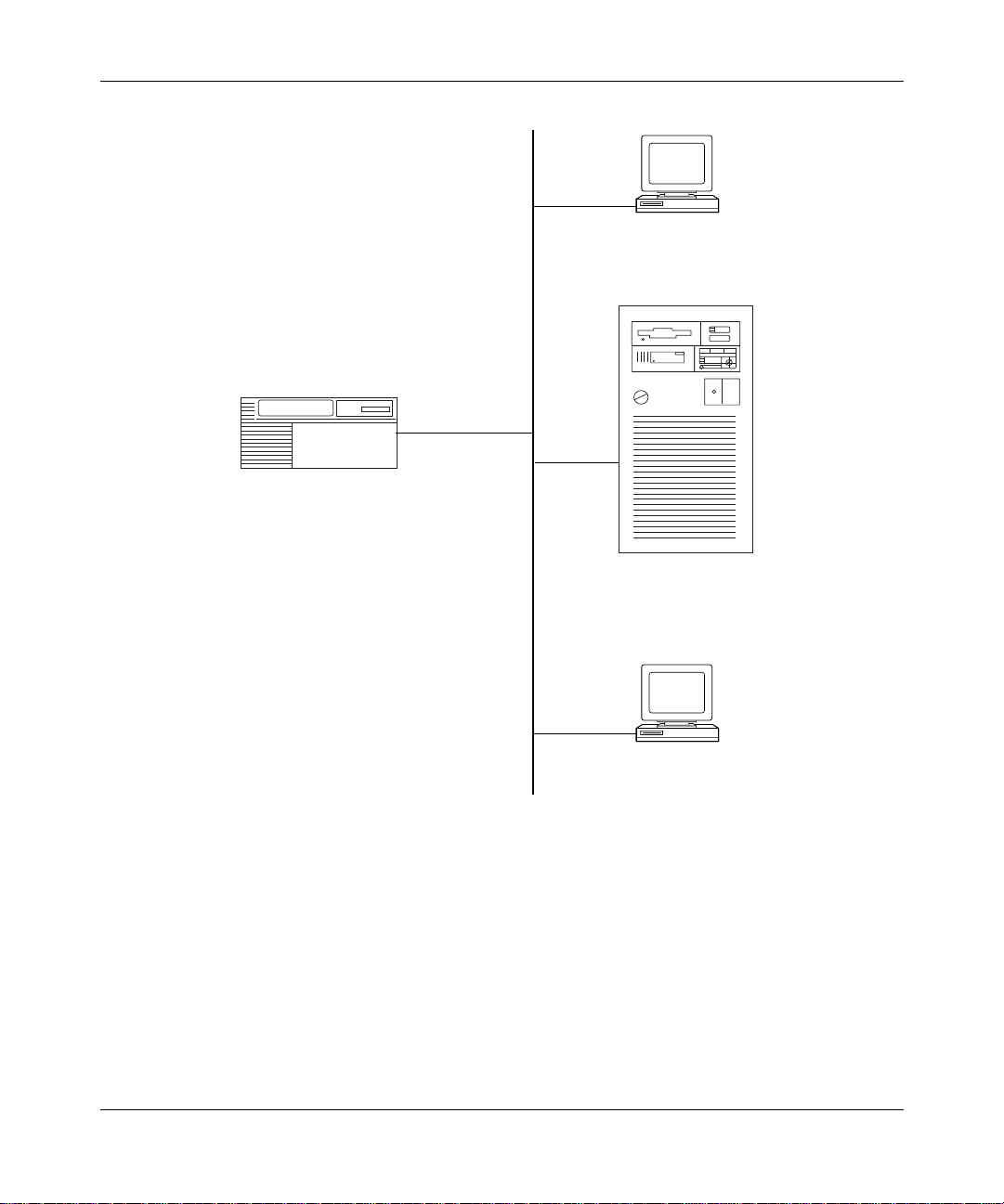
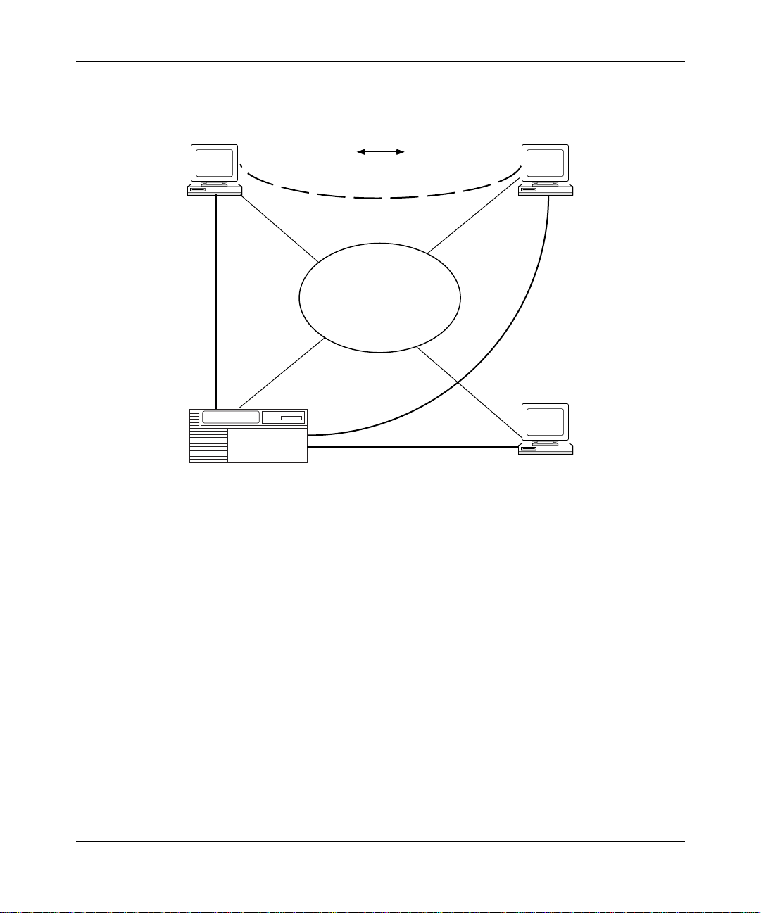
Figure 1-1
303511-A Rev 00
illustrates a simple APPN networ k with the three APPN node types.
1-3
Page 22
Configu ring APPN Service s
Low-entry networking
node (LEN)
APPN network node
(NN)
AS/400 end node
(EN)
Low-entry networking
node (LEN)
APN0001A
Figure 1-1. APPN Network with Different Node Types
1-4
303511-A Re v 00
Page 23
Control Points and Logical Units
APPN uses control points (CPs) to manage node s and network resources by
establishing CP-CP sessions between nodes. All CP-CP sessions use logical unit
(LU) 6.2 sessions.
Advanced Peer-to-Peer Networking Overview
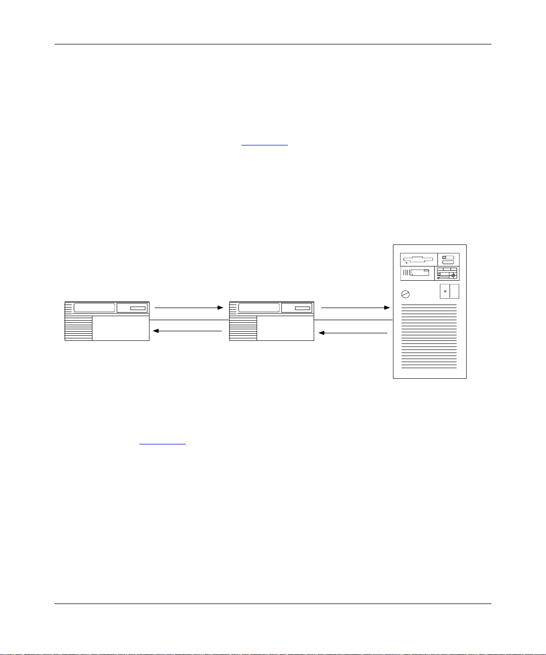
During a CP-CP session (Figure 1-2
information. Network nodes use CP-CP sessions to keep track of the network
topology and directo ry information. Adjacent end nodes use CP-CP sessions to
register resources and to request directory searc hes from the NNS.
Network node
APPN.A
CP-CP, LU-LU
sessions
Figure 1-2. CP-CP and LU-LU Sessions
Network node
), adjacent nodes exchang e network
End node
APPN.C
APPN.B
CP-CP, LU-LU
sessions
APN0002A
303511-A Rev 00
In Figure 1-2, APPN.C registers its local resources with APPN.B, and sends
requests to APPN.B for information abou t the network and its resour ces . APPN.B
functions as a n NNS for APPN.C.
APPN.B has CP-CP sessions with both APPN.A and APPN.C. In this example,
APPN.A and APPN.B exchange network topology and cooperate in directory
searches.
1-5
Page 24

Configu ring APPN Service s
Dependent Logical Unit Requester and Server
APPN’s Dependent Logical Unit Requester (DLUR) supports LU type 0, 1, 2, 3
and LU6.2 dependent logical units within APPN. In contrast to the base APPN
architecture, which uses independent LUs for LU-to-LU sessions, dependent LUs
need a mainframe-based system services control point (SSCP) to establish and
manage LU-to-LU sessions. DLUR allo ws these dependent LUs to use APPN
networks by encapsulating the SSCP control flows within the APPN LU 6.2
sessions. The AP PN network routes the dependent LU-LU data flows.
DLUR works with the dependent LU server (DLUS) component of the virtual
telecommunications a ccess method (VTAM) to provide a path for SSCP flows
between VTAM and dependent LUs across an arbitrary APPN backbone network.
The DLUR node serves as a point of connection for PU2.0 devices (such as
3270-type devices) to attach to an APPN backbone.
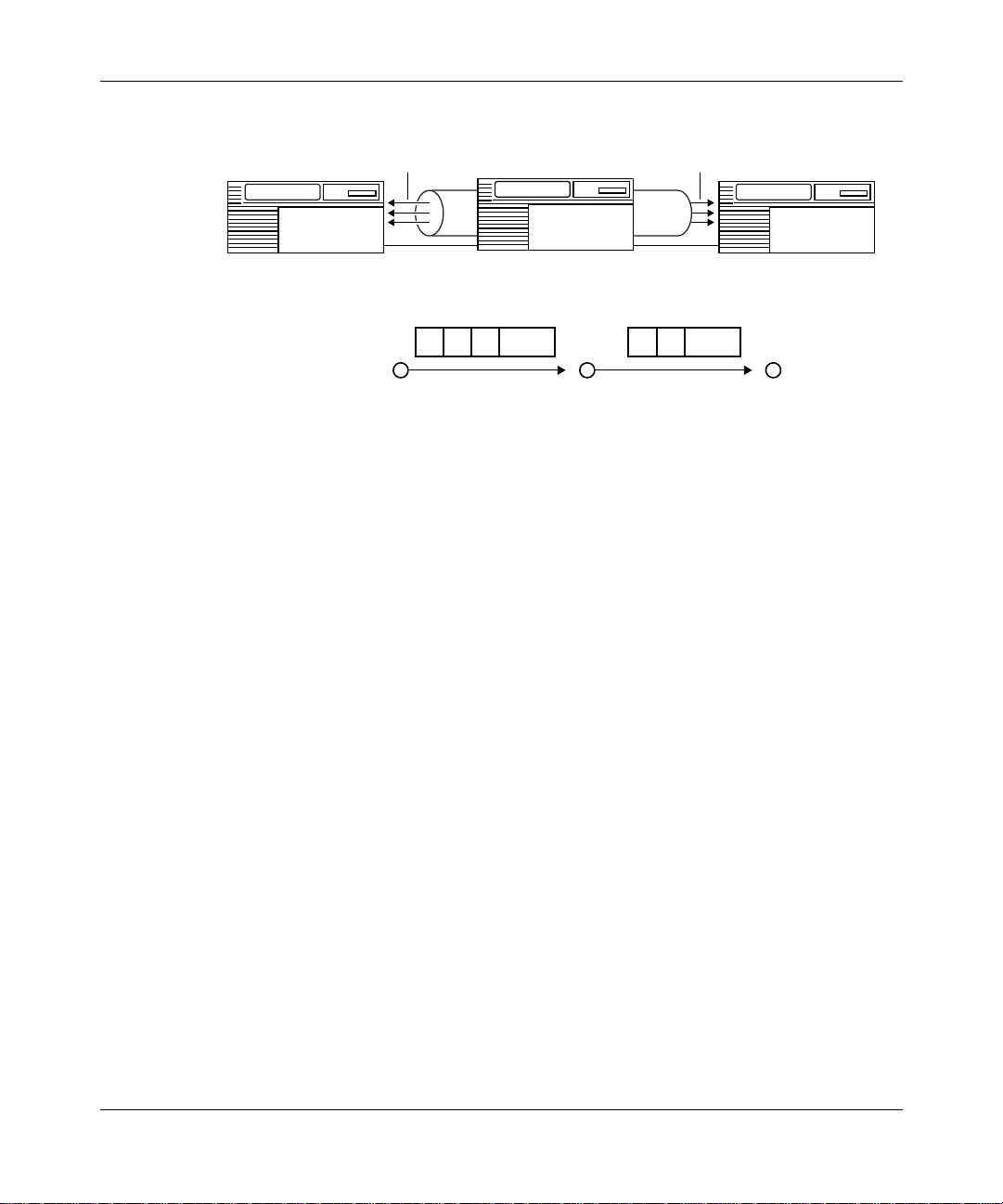
The DLUR and DLUS components in an APPN network allow the SSCP and the
PU2.0 device to exchange control flows across the APPN backbone. DLUR and
DLUS form a tunne l (called a CP-SVR pipe) that allows the SSCP at the DLUS
side of the pipe to send SNA control flows to the PU2.0 device at the DLUR side
of the pipe. The CP-SVR pipe is a pair of LU6.2 sessions that encapsulate the
SSCP control flows.
1-6
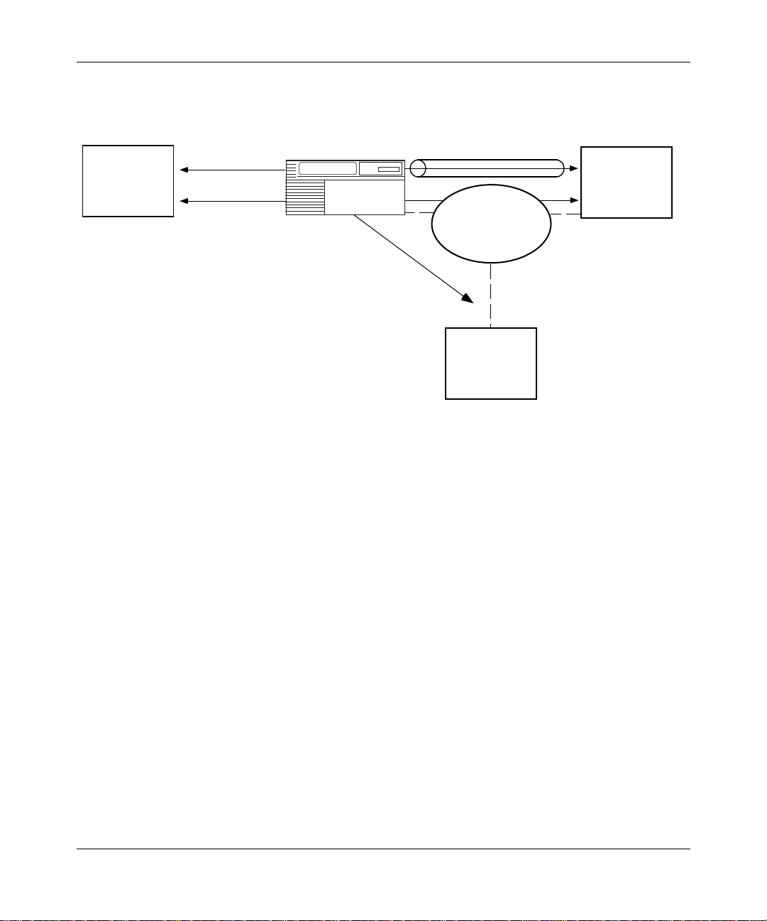
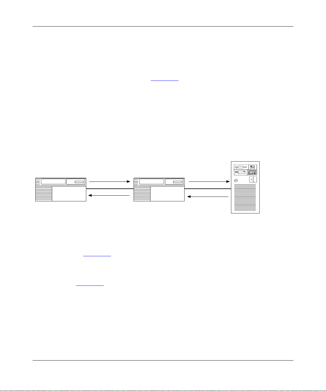
Figure 1-3
illustrates the DLUR and DLUS components in APPN.
303511-A Re v 00
Page 25
Advanced Peer-to-Peer Networking Overview
SSCP sessions
(encapsulated in
CP-SVR pipe
PU2.0
LU-LU sessions
(natively routed by
APPN network)
APPN network node
with DLUR
Figure 1-3. DLUR and DLUS in an APPN Network
Typically, in a large network, multip le DLUS nodes serv e many DLUR nodes
distributed across the APPN backbone. A DLUR node can establish pipes with
seve ral DLUS nodes, altho ugh a single PU2.0 dev ice can recei v e traffic from only
one of them, because the device is only controlled by a single SSCP.
CP-SVR pipe
VTAM
with DLUS
APPN
backbone
VTAM
APN0003A
303511-A Rev 00
When the SSCP and the PU2.0 device excha nge control flows, BINDs establish
the path that the LU-LU session traf fic uses through the network. Since the BIND
flows independe ntly of the CP-SVR pipe, the LU-LU traffic can take a different
path through the network ( the DLUS calculates a route using the topology
database and class of service [COS] definitions). Refer to the “ APPN Services”
section in this chapter for information on the topology database and COS
definitions.
1-7
Page 26
Configu ring APPN Service s
lnterfaces, Ports, and Link Stations
APPN configurat ions comprise interfaces, ports, an d link stations. Figure 1-4
shows ho w interfaces, ports, and li nk stat ions in a simple APPN network relate.
In this guide, the term “interface” has the same meaning as data link
Note:
control (DLC) in IBM publicatio ns.
APPN.NNA
Interface
E51,LLC2,DLC00001
PORT0001
Link Station 1
Link Station 2
Link Station 3
Figure 1-4. Interface, Port, and Link Station Relationship
APPN.ENA
APPN.ENB
APPN.LENC
APN0004A
1-8
303511-A Re v 00
Page 27

Interfaces
Ports
Advanced Peer-to-Peer Networking Overview
Interfaces provide data link control (DLC) processes to ensure reliable deli v ery of
information between adjacent stations using a specific data link protocol, such as
LLC or SDLC.
Each APPN interface can support one or more ports.
A system-assigned DLC number (su ch as DLC00008 ) identifies APPN interfaces
on Bay Networks network nodes.
For informatio n on adding and enabling APPN interfaces on Bay Networks
network nodes, refer to Chapter 2.
A port provides a unique acc ess point (such as a MAC/SAP address pair ) used by
the local Bay Networks network node. A port in an APPN network ha s a DLC
process and a set of configurable parameters.
Link Stations
A link station is a logical connection between adjacent nodes. Link stations use
ports to create this conne cti on. Multiple link stations can exist on a single port,
and multiple link stati ons can exist between the same two nodes. You can
configure a link st ation e ntry, or APPN creates it dynamicall y when a re mote node
initiates a connect ion.
Note:
adjacent link stations to communicate. Wi thin APPN, a link ref ers to a logical
connection between tw o nodes. The term tra nsmission group ( TG) is also used
throughout this manual and has the same meaning as link.
Link stations ha ve a set of configurable paramet ers, such as:
• Link station name and the name of the adjacent node
• Adjacent link station role: primary, secondary, or ne gotiable
• Adjacent link station definitions, such as MAC and SAP addresses
303511-A Rev 00
The term link often refers to the physical components that enable two
1-9
Page 28

Configu ring APPN Service s
Connection Netw o rks
APPN end nodes on a share d access tr ansport facility (SATF), such as a token ring
network, are directly connected to each other; they can communicate with each
other without having to route traffic through an intermediate net wor k node.
However, these end node s still require definitions to other nodes and the nodes
must be accessible over CP-CP sessions. A connection network (CN) simplifies
APPN configurations by reducing the number of connections that you m ust
configure between nodes on an SATF.
When two nodes on the same SATF exist on the same connection network, these
nodes are unaware that they have a direct conne ction to each other; the NNS,
acting as an APPN vi rtual r outing node (VRN), c alcula tes a rou te bet ween the t wo
end nodes so that they can communicate directly. For the end nodes to
communicate with each other over a connection network, the end nodes require a
connection to the VRN and a connection to the NNS.
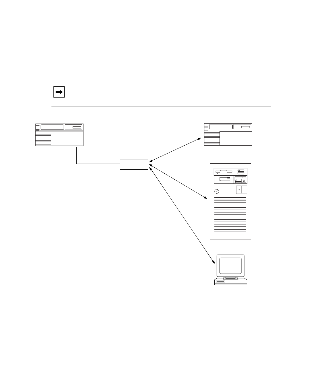
Figure 1-5
such as that betwee n EN2 and EN3, may use resou rces at the networ k node ( NN1)
to establish sessions with each other.
illustrates a sample connec tion network. This connection net work,
1-10
303511-A Re v 00
Page 29
Advanced Peer-to-Peer Networking Overview
EN2 EN3
EN2 EN3
Traffic
SATF
Virtual Routing
Node
303511-A Rev 00
NN1 EN4
APN0005A
Figure 1-5. Sample APPN Connection Network
1-11
Page 30
Configu ring APPN Service s
Intermediate Session Routing
Intermediate sess ion routing (ISR) provides a reli abl e, connection-oriented,
LU-LU session path between nonadja cent APPN nodes . I SR sessi on connectors
(SCs) and a session connection manager (SCM) forward sessions through the
intermediate network node (Figure 1-6
At session endpoints, the LU, with control point services, establishes a session
with a session partner and route s session data back and forth with the partner LU.
INTERMEDIATE network nodes do not control the LU endpoints, and LU
services cannot be invoked on these nodes. ISR forwards session data to the next
node along the session path.
Intermediate
LU-A to LU-C
Session
Network Node B
NNB
).
End Node C
LU-C
Network Node A
LU-a
ISR Services
LU-A to LU-C
Session
Figure 1-6. Nonadjacent LU-LU Session Through an Intermediate Node
In Figure 1-6, LU-A and LU-C are nonadjacent session partners. ISR at NNB
forwards session data between the nonadjacent nodes, LU-A and LU-C. NNB
creates a session connec tor (SC) for each session passing through it.
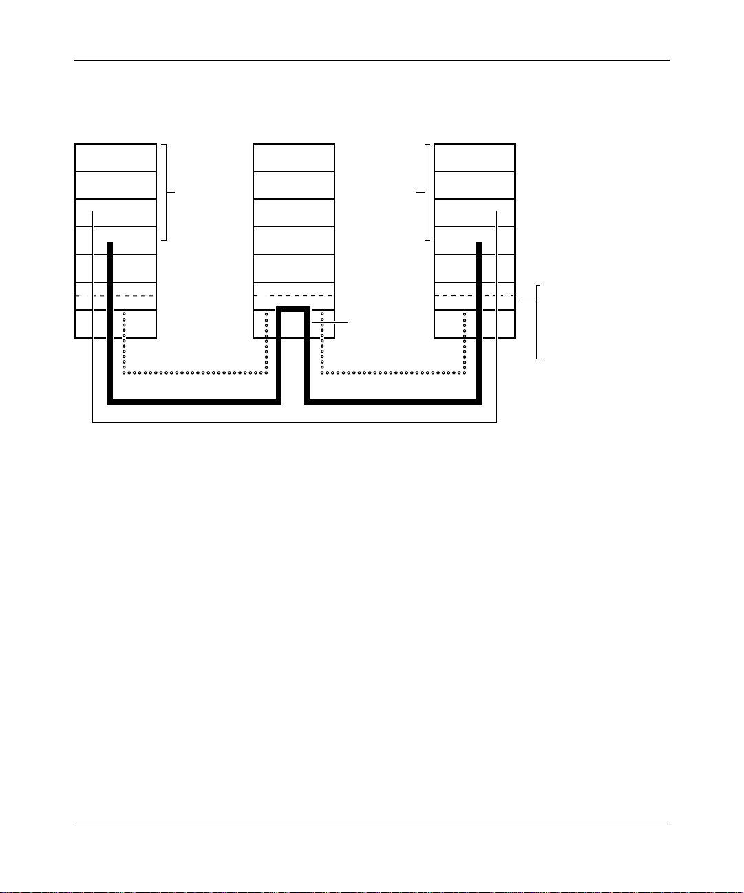
Figure 1-7
illustrates ISR funct ion placement in the SNA layered architecture.
Routing takes place at the SNA Layer 4, called the Transmission Control layer.
Layer 4 performs flow co ntrol operations, specifically segmentation and
reassembly, and pacing.
1-12
APN0006A
303511-A Re v 00
Page 31

Advanced Peer-to-Peer Networking Overview
APPN
End Node
Applicaton
7
6
5
4
3
2
1
Logical
Unit (LU)
Connection
Oriented
Logical Link
Transport Connection
APPN
Network Node
7
6
5
4
3
2
1
LU-LU Session
Application Data
Logical
Unit (LU)
Session
Connector
Connection
Oriented
Logical Link
Transport Connection
APPN
End Node
Applicaton
Figure 1-7. APPN ISR Ro ut in g Function s in SN A A rchite ct ure
7
6
5
Transmission Control
4
Flow Control
3
-Adaptive Pacing
-Segmenting/
2
Reassembly
1
APN0007A
Packet Segmentation and Reassembly
T o m aximize network perf ormance, ISR sends t he la rge st pack et size a llo wab le on
each network interface that you configure for APPN. Intermediate nodes, when
necessary, segment and reassemble packets of different packet sizes. The Max RU
Size for ISR Sessions parameter sets the maxim um p ack et size fo r y our AP PN
configuration.
Adaptive Pacing
ISR’ s Ada pti ve Pa cing controls d ata f lo w a nd congesti on b y managing t he number
of messages the network node receives during a session. To prevent memory
consumption, APPN use s “pacing windows” to control the maximum number of
incoming messages. During network activit y, this pacing window changes
dynamically, allowing the receiving node to adjust the rate at which data flows
into its buffers.
303511-A Rev 00
1-13
Page 32

Configu ring APPN Service s
To specify the maximum size of the adaptive pacing window, configure the ISR
Receiv e Pacing Window parameter.
High Performance Routing
APPN’s high performance routing (HPR) increases data routing performance and
reliability. HPR allows high-speed forw arding in intermediate nodes at the Data
Link Control laye r (Layer 2) of SNA, operating much faster than the intermediate
session routing (ISR) bas e component in APPN. HPR consumes fewer network
resources (memory and control pr ocessor) by
• Minimizing storage and processing activities in intermediate nodes
• Reducing the amount of error recovery on individual lines
• Implementing nondisruptive path switching function that reroutes se ssions
around failed links or nodes
HPR uses the Rapid Transport Protocol (RTP) and Automatic Network Routing
(ANR). RTP also supports adaptive rate bas ed (ARB) congestion control.
1-14
Figure 1-8
the SNA Data Link Control layer. Layer 2 performs reliable, sequential delivery,
selective retransmission, and nondisruptive rerouting using RTP, as described in
this section.
illustrates HPR in the SNA layered architecture. Routing takes place at
303511-A Re v 00
Page 33
Advanced Peer-to-Peer Networking Overview
RTP Endpoint
(End Node or
Network Node)
7
Application Application
6
5
4
3
2
1
Transport-Oriented LLC
Logical
Unit (LU)
Connectionless LLC
ANR Router Node
(Network Node)
7
6
5
4
3
2
1
Session
Logical
Unit (LU)
Connectionless
(ANR) Routing
with Priority
RTP Endpoint
(End Node or
Network Node)
Figure 1-8. APPN HPR Routing Functions in SNA Architecture
7
6
5
4
3
Data-Link Control
2
Reliable.
1
Sequential Delivery
Selective Retransmission
Nondisruptive Rerouting
APN0008A
303511-A Rev 00
1-15
Page 34
Configu ring APPN Service s
Rapid Transport Protocol
RTP is a connection-oriente d, f ull-duplex protocol tha t supports data in highspeed networks at APPN NN endpoints. HPR uses RTP connections to transport
LU-LU and CP-CP tr affic. A single RTP connection allows traffic from multiple
APPN sessions (requesting the same cla ss of service) to share the same logical
“pipe.” This conserves network resources by mi nimizing the role of intermediate
NNs in the path, and by reducing error rec overy and flow control operations.
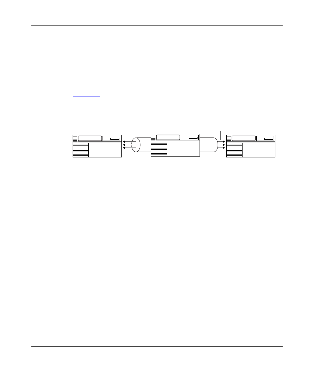
Figure 1-9
endpoint nodes over a logical pipe .
illustrates an RTP connection supporting multiple sessions between
Multiple
Sessions
NN
Endpoint Node
APN0009A
NN
Endpoint Node
Multiple
Sessions
RTP Connection
over Logical Pipe
NN
Intermediate Node
Figure 1-9. HPR RTP Connection Supporting APPN Sessions
RTP functions include:
• Non-disruptive path switching
• End-to-end error recovery
• End-to-end flow and congestion control
Non-Disruptive Path Switching
The HPR non-disruptive path switch dynamically reroutes RTP connections
around failed links or nodes. If a path fails, the RTP component at the NN
endpoint of the logical link c alculates a new path based on the desired class of
service and transmiss ion priority (if it exist s). RTP per forms the switching
transparently so tha t the session is unaware that rerouting is taking place.
Non-disruptive path switching forwards and reverses traffic to follow different
routes through the networ k, and also recovers traffic that was lost at the time of
failure.
1-16
303511-A Re v 00
Page 35

Advanced Peer-to-Peer Networking Overview
End-to-End Error Recovery
End-to-end error recovery enables APPN NN en dpoints to recovery lost traffic.
HPR endpoint NNs a lways perform end-to-end recovery . Howev er, Site Manager
allows you to sp ecify ba se APPN l ink-le v el e rror r ecov e ry, where error recov ery i s
done on every link, consuming more network resources.
High-speed links gener ally have lo w error rates. Therefore, link-level
Note:
recove ry may not be necess ary in the higher speed HPR configurat ions.
When link lev el recovery is turned off and an error is detected, the packet is
discarded, resulting in a gap in the stream of byte s over the R TP connection. When
the R TP connection endpoint NN detects the gap in the incoming byte stream, it
informs the sender to begi n retransmit ting from the first b yte afte r this point in the
stream. RTP supports selective retransmission of parts of the byte stream, when
the RTP endpoint requests a range of bytes for retransmission.
End-to-End Flow and Congestion Control
303511-A Rev 00
Operating at t he NN sending and receiving endpoints of an RTP connection, HPR
uses a p reve ntative m echanism called adaptive rate-based (ARB) congestion
control. ARB monitors, predicts, a nd regulates the flow of traffic into the network
as conditions change. When the networ k approaches congestion (increased delay,
decreased throughput), ARB reduces the input traffic rate so that a recipient
endpoint NN can adequately handle the traffic.
With multiple RTP connections o ver a single link, the ARB function regulates the
flow of traffic in all connections. This provide s fairness to all connections.
With multiple SNA sessions over a single RTP connection, HPR’s adaptive
session-level pacing maintains fairness among the sessions. This prevents one
session from unfairly consuming network resources, compared to other sessions
on the R TP connection.
1-17
Page 36

Configu ring APPN Service s
Automatic Network Routing
Automatic network rout ing (ANR) minimizes storage and processing
requirements for routing packets through intermediate nodes. ANR functions
include:
• Fast packet switching
• Session transparency
• Source routing
Fast Packet Switching
ANR operates at the Data Link Control layer of the SNA archite cture. Operating
at a lower layer tha n APPN ISR improv es packet switching perfor mance in the
intermediate nodes. Functions typically performed at the intermediate node, such
as link-level recovery, segmentation, flow and congestion control, are perfo rme d
at the RTP connection endpoints.
Session Transpare n cy
Intermediate node s are not aware of the SNA sessions or the RTP connections
established acro ss the nodes. This eliminates the need for storin g routing tables
and consuming resources (memory an d buffers) at the intermediate nodes.
1-18
Source Routing
ANR uses a source routing algorithm. ANR carri es the routing information in the
network header of each packet. For each activated link, an ANR label is
dynamically assigne d to the pack et. As a packet traverses the network, each node
strips of f the information it uses in the packet header before forwarding it,
allowing the next node to easily find its routing information at a fixed pla ce in the
header. This allows faster switching through a node. Additionally, there is no
ANR restriction on the number of hops in the network.
Figure 1-10
illustrates ho w ANR routes pa cke ts ov er an APPN HPR network. The
intermediate network node strips the first routing label (A1) from the network
header before forwarding the pack e t on the A1 link. C5 represents the endpoint in
the last HPR node.
303511-A Re v 00
Page 37
Advanced Peer-to-Peer Networking Overview
RTP Connection
A1 C5
Sessions Sessions
Sending Endpoint Node
NN1
Figure 1-10. HPR ANR Routing and Packet Handling Operations
APPN Services
The APPN services on the NN include:
• Session services
• Directory services
• Topology and routing services
• Configuration services
• Management services
NN2
Intermediate Node
A1 C5 FF Data C5 FF Data
A1 Stripped off at NN2 Before Delivery to NN3
Receiving Endpoint Node
NN3
APN0010A
Session Services
Session services (SS) generate s unique session identifiers, acti vates and
deactivates CP-CP sessions to exchange network informatio n, an d assists LUs in
initiating and activating L U-LU sessions. Session services:
• Invokes directory servic es to locate a partner LU
• Invokes topology and routing se rvices (TRS) to calculate the optimal route
between the origin and destina tion node
• Inf o r ms man a g emen t servi c es (MS ) a b o ut newl y ac t iva t e d or deac tivated
CP-CP sessions
303511-A Rev 00
1-19
Page 38

Configu ring APPN Service s
Directory Services
Directory services (DS) manages the directory database and locates network
resources through out an APPN networ k. To loc ate network resources, direc tory
services at e ach node collects r esource information an d maintains the inform at ion
in a local directory database. Through a CP-CP session betwee n an APPN
network node and an adjacent APPN end node, the APPN network node registers
(by end node request) the APPN end node’s resources in its local directory
database.
An APPN network node maintains database entrie s for
• Local resources (LUs and the CP)
• End node resources within the APPN network node’ s domain
• End node or network node resources outside the APPN network node’s
domain (called cross-domain resources)
An APPN end node or low-entry networ king node maintains database entries for
• Local resources
• Local resources on adjacent nodes tha t have peer-to-peer communication
sessions (without the presence of an APPN network node or control point, in
the case of a peer-to-peer end node and low-entry networking node)
Topology and Routing Services
T opol ogy an d routing servi ces (TRS) reside s in e ver y APPN networ k node and, in
lesser form, in every APPN end node and low-entry networking node. In APPN
network nodes, TRS collects and exchanges informatio n on other net work nodes,
and the links between them. For LU-LU sess ions, TRS provides the best route
between any t wo LUs. In APPN end nodes and low-entry networking nodes, TRS
collects information on links and adjacent nodes.
In APPN network nodes, TRS creates and maintai ns the class-of-service (COS)
database and a copy of the network topology database. The network topology
database contains information on APPN network node connections to other
network nodes and connection networks. (A connection networ k is a method of
defining an APPN node attachment to a sha red-access transport facility, reducing
intermediate node routing and definition requi rements.)
1-20
303511-A Re v 00
Page 39

In APPN end nodes, TRS creates and maintains the COS database, and maintains
the local topology database (also maintained by TRS at the network node). The
local topology data base contains information on connect ions involving the local
end nodes: end node-to-end node , end node-to- network node, and end
node-to-virtual routing node.
For LU-LU sessions, TRS computes the optimal route through an APPN network
between the two nodes on which the LUs reside. A route in an APPN network is
an ordered sequence of nodes and transmission groups (TGs) that represents a
path from an origin to a destination, called a Route Selection Control Vector
(RSCV). In APPN end nodes, TRS uses the local database to select possible
transmission groups from the end node to an adjacent node. In APPN network
nodes, TRS uses the informati on provi ded by the two end nodes, togethe r with the
information in the netw ork node’s COS and topology database, to select a route.
Configuration Services
Configura tion services (CS) manages links to adjacent APPN nodes . The APPN
node operator faci lity (NOF) initializes configuration services through Site
Manager.
Advanced Peer-to-Peer Networking Overview
The basic configur ation functions are:
• Node definition
• Interfaces
• Ports
• Adjacent link stations
• Connection networks
• Directory services
Refer to Chapter 3, “Editing APPN Parameters,” for detailed information on
configuring APPN nodes.
Management Services
Management service s (MS) cont rols and m onito rs the node ’s resources. If an error
condition occur s, APPN rec ei v es or gener ates e ve nt mes sages abo ut resour ces and
conditions. F or information on the APPN event messa ges, refer to Event Messages
for Routers.
303511-A Rev 00
1-21
Page 40

Configu ring APPN Service s
For More Information About APPN
For more information about APPN, IBM SNA, and related subjects, refer to the
following I BM publications:
• IBM Systems Network Arc hitecture: LU6.2 Reference: Peer Protoc ols
(SC31-6808)
• IBM Systems Network Architecture: APPN Architecture Reference
(SC30-3422)
• IBM Systems Network Architecture: Management Services
(SC30-3346)
• IBM APPN Architecture and Product Implementation Tutorial (GG24-3669)
• IBM AS/400 Advanced Peer-to- Peer Networking
(GG24-3287)
• IBM Systems Network Arc hitecture: Technical Overview
(GC30-3073)
• IBM Systems Network Architecture: Concepts and Products
(GC30-3072)
1-22
• IBM System Network Arc hitecture: Introduction to Sessions between Logic al
Units (GC20-1869)
303511-A Re v 00
Page 41

Chapter 2
Enabling APPN Services
This chapter describes how to enable APPN services on:
• Logical Link Control 2 (LLC2) media, including Ethernet, token ring, and
frame relay
• LLC2 media using Source Routing Bridge (SRB) encapsulation formats over
Ethernet, FDDI, SMDS, frame relay, and Point-to-Point Protocol( PPP)
• Synchronous Data Link Control (SDLC) links in point-to-point and
multipoint netwo rks
This chapter assumes that you have read Configuring and Managing Routers with
Site Manager and that you have:
1. Opened a configuration file
2. Specified router hardware if this a local mode configura tion file
3. Selected the connector on which you are enabling APPN
Using the Parameter Descriptions
Each APPN parameter description provides information about default settings,
valid parameter options, the parameter function, inst ructions for setting the
parameter, and the Management Information Base (MIB) object ID.
The Technician Interface allows you to modify parameters by issuing
commit
modifying parameters using Site Manager. For more information about using the
T echnician Interface to access the MIB, refer to Using Technician Interface
Software.
303511-A Rev 00
commands with the MIB object ID. This process is equivalent to
set
and
2-1
Page 42

Configu ring APPN Service s
Caution:
The Technician Interface does not verify tha t the value you enter fo r
a parameter is valid. Entering an invalid value can corrupt your configur ation.
Enabling APPN over LLC2 Interfaces
When you configure APPN on LLC2 interfaces, such as Ethernet and token ring,
the Configuration Manager requests media access control ( MAC) and service
access point (SAP) addresses. On synchronous interfaces where you are
configuring APPN over frame relay, the Configuration Manager requests a data
link connection identifier (DLCI) address and a SAP address.
T o e nable APPN on Etherne t, toke n ring , or B ay Networ ks synchronous interfaces
using frame relay:
Select APPN from the Select Protocols win dow.
1.
This menu appears after you select either a link or net module connector that
requires a wide area network (WAN) circuit. The Configuration Manager
automatically sel ects the LLC2 option.
Click on OK.
2.
For frame relay and Ethernet networks, the “Use Source Route
Encapsulation? ” dialog box appears (Figure 2-1
).
2-2
Click on Cancel if you are configuring standard LLC over Ethernet, or if
3.
you are configuring frame relay using the RFC 1490 routing standard.
303511-A Re v 00
Page 43

Enabli n g APPN Ser vices
Figure 2-1. Source Route Encapsulation Dialog Box
To configure Bay Networks SRB over Ethernet or frame relay using the RFC
1490 bridging standard , cl ic k on OK and refer to the next section, “Enabling
APPN over LLC2 Interfaces Using SRB,” for information on the additional
screens that appea r.
The APPN Local Node Name Configuration window appears (Figure 2-2
Figure 2-2. APPN Local No de Name Conf ig uration Wi ndow
Specify the Local Node Name parameter, as follows:
4.
).
303511-A Rev 00
2-3
Page 44

Configu ring APPN Service s
Parameter: Local Node Name
Default: None
Options: An y valid name with up to 17 characters in the format
<NETID>.<CPNAME>; NETID
characters followed by a period, and
with up to 8 characters. (Do not enter the angle brackets; these are a
conve ntion used to indicate a substitutable variable.)
Function: The Local Node Name parameter identifies the unique name of the
network and the Bay Networks router node name.
Instructions: Enter the node name by fi rs t specifying up to 8 characters in the network
ID name, type a period, then enter a control point name with up to 8
characters. You must use uppercase c haracters only a nd the first character
must be non-numeric. Blank spaces (leading, trailing, and embedded) are
not allowe d in the node name. For example, NETWORKA.SYSTEMA is
a valid entry for the Local Node Na me parameter.
MIB Object ID: 1.3.6.1.4.1.18.3.5.14.1.1.4
Click on OK to add the local node name.
5.
For frame relay conf igurations, the APPN/FR Configuration window appears
(Figure 2-3
). If you are configuri ng standard LLC over Ethernet, the
Configura tion Manager displays the APPN Configuration windo w where you
specify a MAC addr ess instead of the DLCI address.
is the global network name with up to 8
CPNAME
is the control point name
2-4
303511-A Re v 00
Page 45

Figure 2-3. APPN/FR Configuration Window
Specify the DLCI Address (for frame relay only), MAC Address, and
6.
SAP parameters, as follows:
Enabli n g APPN Ser vices
Parameter: DLCI Address
Default: None
Options: Valid range depends on the frame relay address length as follows:
Address Length Range
2 bytes 16-1007
3 bytes 1024-64511
4 bytes 131072-8257535
Function: The DLCI is the frame relay PVC identification number. The frame relay
network uses the DLCI to direct basic data flow.
Instructions: Enter a decimal number within the valid range.
MIB Object ID: 1.3.6.1.4.1.18.3.5.14.1.3.1.38
303511-A Rev 00
2-5
Page 46

Configu ring APPN Service s
Parameter: SAP (hex)
Default: None
Options: Any unique SAP 2-digit hexadecimal value, usually 04 with APPN.
Function: Specifies a SAP address that lets multiple applications and protocol
entities in a single comput er share a MAC address.
Instructions: Enter a 2-digit hexadecimal value.
MIB Object ID: 1.3.6.1.4.1.18.3.5.14.1.3.1.38
Parameter : MAC Address
Default: None
Options: Any unique 48-bit 12-digit hexa decimal MAC-level address
Function: Specifies a unique MAC -l evel address for this port.
Instructions: Enter a 12-digit hexadecimal MAC-level address in most significant bit
(MSB) noncanonical format, regardless of the media.
MIB Object ID: 1.3.6.1.4.1.18.3.5.14.1.3.1.38
Click on OK.
7.
The Adjacent Link Station dialog box ap pear s (Figur e 2-4
Figure 2-4. Adjacent Link Station Dialog Box
2-6
).
303511-A Re v 00
Page 47

Enabli n g APPN Ser vices
Click on OK to configure APPN adjacent link station parameters now
8.
.
For informatio n on configuring addjacent link stations, go to the section in
Chapter 3
Click on Cancel.
9.
entitled “Editing APPN Adjacent Link Stations.”
Go to Chapter 3
for information about configuring APPN.
Enabling APPN over LLC2 Interfaces Using SRB
If you are configur ing LLC2 interfaces such as Ethernet, FDDI, SMDS, frame
relay, and PPP, you can use SRB encapsulation formats. F or Ethernet (Bay
Networks proprieta ry SRB over Ethernet) and frame relay (RFC1490 Bridging
Standard), start at the Source Route Encapsulation dialog box (Figure 2-5
proceed as follo ws:
) and
303511-A Rev 00
Figure 2-5. Source Route Encapsulation Dialog Box
Click on OK.
1.
The Source Routing Global Parameters window appears (Figure 2-6
).
2-7
Page 48

Configu ring APPN Service s
Figure 2-6. Source Routing Global Parameters Window
Edit the SR Bridge Internal LAN ID and the SR Bridge ID parameters in
2.
the Source Routi ng Gl o bal Para meters window.
These are man dat o ry par am et ers that you must specify before you can
proceed.
2-8
303511-A Re v 00
Page 49

Parameter: SR Bridge Internal LAN ID
Default: 0x1
Range: 0x1 to 0x0fff
Function: Specifies this bridge’s internal LAN ID.
Instructions: Assign an internal LAN ID that is unique among all other internal LAN
IDs and ring IDs in the network.
MIB Object ID: 1.3.6.1.4.1.18.3.5.1.1. 2.1. 4
Parameter: SR Bridge ID
Default: 0x1
Range: 0x1 to 0x0f
Function: Specifies this bridge’s ID and identifies the Bay Networks source ro uting
bridges in the network.
Instructions: Assign the same value to all Bay Networ ks source routing bridges in the
network (unless two bridges operate in parallel). The SR bridge ID must
be unique among any other third -par ty bridge IDs in the network.
Enabli n g APPN Ser vices
MIB Object ID: 1.3.6.1.4.1.18.3.5.1.1. 2.1. 5
For details about co nfiguring the source rout ing parameters on this window, refer
to Configuring Bridging Services.
Click on OK.
3.
The Edit SR Interface window appears (Figure 2-7
303511-A Rev 00
).
2-9
Page 50

Configu ring APPN Service s
Figure 2-7. Edit SR Interface Window
Edit the Source Routing Ring Number parameter in the Edit SR
4.
Interface window.
This is the only parameter that you must specify before you can proceed.
2-10
303511-A Re v 00
Page 51
Parameter: Source Routing Ring Number
Default: 0x0
Range: 0x0 to 0x0fff
Function: Identifies the ring number (ring ID) of this sour ce routing circuit.
Instructions: Assign a ring number (ring ID) to thi s source r outin g circuit that is uniq ue
among any other ring IDs, group LAN IDs, or internal LAN IDs in the
network.
MIB Object ID: 1.3.6.1.4.1.18.3.5.1.1. 2.1. 6
For details on ho w to configure the source routing parameters on this window,
refer to Configuring Bridging Se rvices.
Click on OK.
5.
Enabli n g APPN Ser vices
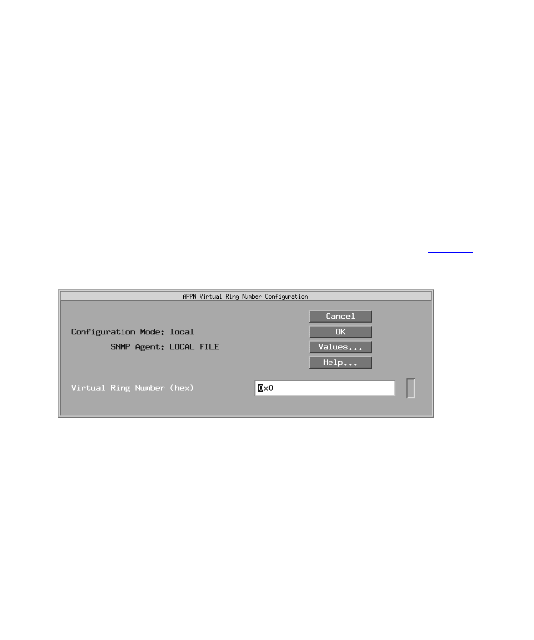
The APPN Virtual Ring Number Configuration window appears (Figure 2-8
Figure 2-8. APPN Virt u a l Ri ng Nu m ber Configuration Window
Edit the Virt ual Ring Number parameter, as follows:
6.
).
303511-A Rev 00
2-11
Page 52

Configu ring APPN Service s
Parameter: Virtual Ring Number (hex)
Default: None
Range: 1 to 4095
Function: Specifies the unique SRB ring number to be used by APPN. It must be
unique in the SRB network. This means that the Virtual Ring Number
must be different not only from the ring IDs specified in the SRB
configura tion, b ut di f ferent also from othe r Bay Netw orks route rs ru nning
APPN on LLC2/SRB media.
Instructions: Specify the unique LLC ring number in the range 1 to 4095.
MIB Object ID: 1.3.6.1.4.1.18.3.5.1.6. 2.25
Click on OK.
7.
If this is the first interface for which you are configuring APPN, the APPN
Local Node Name Configurat ion window appears (Figure 2-2
the first interface for which you are configuring APPN, the APPN
Configura tion window for your specific network appears. Refer to these
figures and the ste ps that follow them to complete the APPN conf iguration.
). If this is not
Enabling APPN Interfaces over SDLC
To configure APPN on synchronous interfaces (COM1, COM2, etc.) using the
SDLC protocol:
Select SDL C from the WAN protocol s window.
1.
The Configuration Manager displays the SDLC Line Parameters window
(Figure 2-9
2-12
).
303511-A Re v 00
Page 53
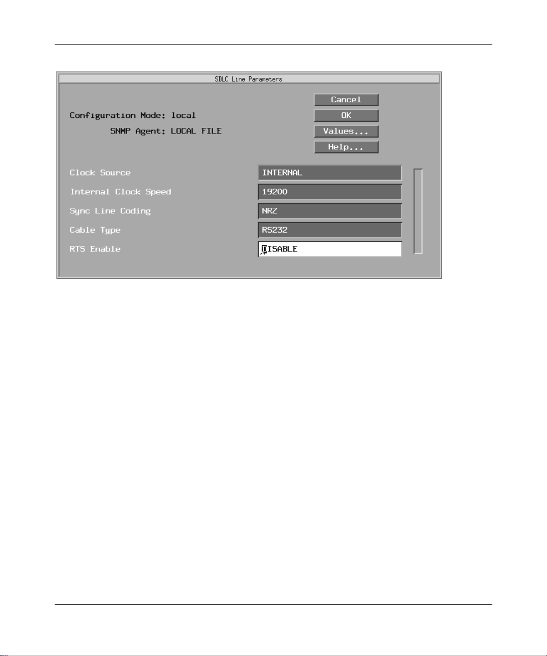
Figure 2-9. SDLC Line Paramet ers W in dow
Enabli n g APPN Ser vices
303511-A Rev 00
Edit the Cloc k Source, In terna l Clock Speed, Sync Line Coding, Cable
2.
Type, and RTS Enable paramet ers, as follows:
2-13
Page 54

Configu ring APPN Service s
Parameter : Cloc k Source
Default: Internal
Options: External
Function: Identifies whether the rout er provides clocking (INTERNAL) or receives
clocking (EXTERN AL) from the other device. The paramet er specifies
the origin of the synchronous timing signals. If you set this parameter to
Internal, this router supplies the required timing signa ls. If you set this
parameter to External , an external network device supplies the require d
timing signals.
Use this parameter when connecting the SNA equipment directly to the
router . Either the route r or the SN A equipment can define the speed of the
SDLC link. You must configure one devi ce to internal clocking, and the
other devic e to external clocking.
Instructions: For direct connec tion to a contr ol unit, such as an IBM 3174, set to
Internal. For connection to a modem, set to External. For direct
connection to a n IBM 3745, eith er t he route r or the IBM 3745 c an pro vide
the clock source. If the IBM 3745 does not provide clocking, set to
Internal.
|
Internal
MIB Object ID: 1.3.6.1.4.1.18.3.4.5.1. 13
2-14
303511-A Re v 00
Page 55

Enabli n g APPN Ser vices
Parameter : Inte rnal Cl oc k Sp eed
Default: 19200 KB
|
Options: 1200 B
19200 B
125 KB | 230 KB| 420 KB | 625 KB | 833 KB |
1.25 MB | 2.5 MB | 5 MB
Function: Sets the clock speed of an internally supplied clock when Clock Source is
set to Internal. Attached devices must be capable of operating at the
specifie d speed. Some of the more common allowed speeds for IBM
products are as follows:
-- An IBM 3274 with a n V.24/RS-232 interface suppo rt s up to 960 0 bps.
-- An IBM 3274 with a V.35 interface supports up to 64 Kb/s.
-- An IBM 3174 with a V.24/RS-232 interface supports up to 19200 bps.
-- An IBM 3174 with a V.35 interface and running Licensed Internal
Instructions: Click on Values and set the clock speed for the internal cloc k to the
desired data transmi ssion rate across the synchronous line.
This parameter is unavailable when Clock Source is set to External.
MIB Object ID: 1.3.6.1.4.1.18.3.4.5.1. 14
2400 B | 4800 B | 7200 B | 9600 B
|
32000 B
Some support speeds up to 19200 bps.
Code-C supports up to 256 Kb/s.
|
38400 B | 56 KB | 64 KB
|
|
303511-A Rev 00
2-15
Page 56

Configu ring APPN Service s
Parameter: Sync Line Coding
Default: NRZ
|
Options: NRZ
Function: Sets the same line coding value f or all de vi ces attac hed to the same SDLC
Instructions: Select NRZ or NRZI. NRZI Mark is not generally used for SDLC.
MIB Object ID: 1.3.6.1.4.1.18.3.4.5.1. 88
Parameter: Cable Type
NRZI | NRZI Mark
link. You can change the value of this parameter to match the line coding
of a device at the other end of the line.
This parameter i s re le v ant on ly for the AN and ASN routers , and the Octa l
Sync module. Other Bay Networks router platforms use NRZ encoding.
NRZ -- Indicates Non-Return to Zero encoding.
NRZI -- Indicates Non-Return to Zero Inverted encoding.
NRZI Mark -- Indicates Non-Return to Zero Inverted Mark encoding.
Default: RS232
|
Options: Null
Function: Spec ifies the cabl e int erfa ce to the network.
Instructions: Click on Values and select the installed cable interface type.
MIB Object ID: 1.3.6.1.4.1.18.3.4.5.1. 83
Parameter: RTS Enable
Default: Disable
Options: Enable
Function: Controls the toggling of the Request to Send (RTS) signal on the
Instructions: Click on Values and select Enabled or Disabled. For manual dial modems
MIB Object ID: 1.3.6.1.4.1.18.3.4.5.1. 16
2-16
RS232 | RS422 | V35 | X21
|
Disable
interface .
(2-wire), set this para meter to Enabled. For leased modems (4-wire), set
this parameter to Disabled.
303511-A Re v 00
Page 57
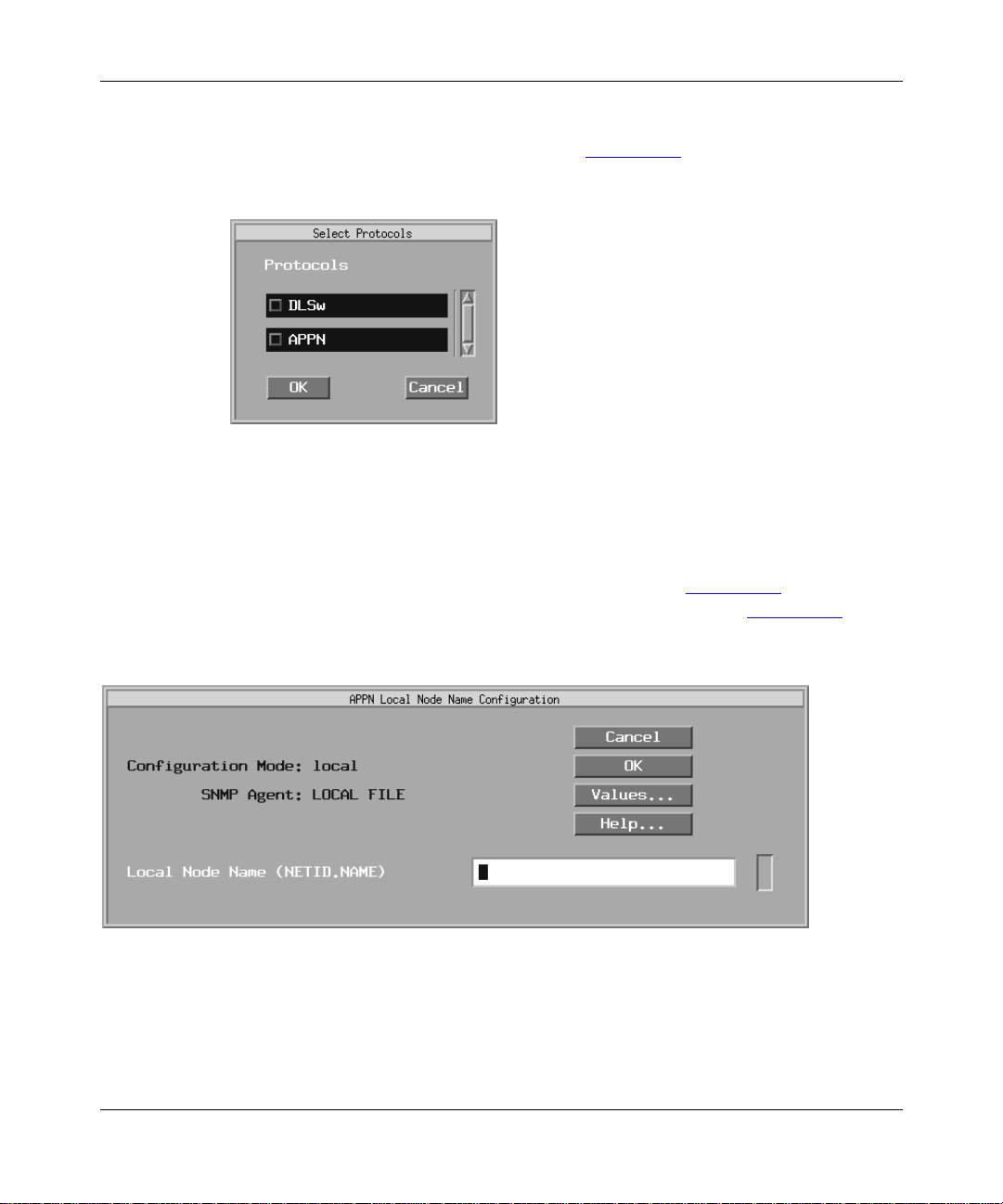
Enabli n g APPN Ser vices
Click on OK.
3.
The Select Protocols window appears (Figure 2-10
Figure 2-10. Select Prot ocols Window
Select APPN and click on OK.
4.
).
If this is the first interface for which you are configuring APPN, the APPN
Local Node Name Configurat ion window appears (Figure 2-11
). Otherwise,
the APPN SDLC Address Configuration window appears (Figure 2-12).
Figure 2-11. APPN Lo cal No de Name Conf ig uration Wi ndow
Specify the Local Node Name parameter.
5.
303511-A Rev 00
2-17
Page 58

Configu ring APPN Service s
If this is not the first APPN interface on this router, omit this step and go to
Step 7.
Parameter: Local Node Name
Default: None
Options: Any valid name with up to 17 characters in the format
<NETID>.<CPNAME>; NETID
characters followed by a period, and
with up to 8 characters. (Do not enter the angle brackets; these are a
conve ntion used to indicate a substitutable variable.)
Function: The Local Node Name parameter identifies the unique name of the
network and the Bay Networks router node name.
Instructions: Enter the node name by fi rs t specifying up to 8 characters in the network
ID name; type a period; and then enter a control point name with up to 8
characters. You must use uppercase c haracters only a nd the first character
must be non-numeric. Blank spaces (leading, trailing, and embedded) are
not allowe d in the node name. For example, NETWORKA.SYSTEMA is
a valid entry for the Local Node Na me parameter.
is the global network name with up to 8
CPNAME
is the control point name
MIB Object ID: 1.3.6.1.4.1.18.3.5.14.1.1.4
Click on OK to add the local node name.
6.
The APPN SDLC Address Configuration window appears (Figure 2-12
Figure 2-12. APPN SDLC Address Configuration Window
2-18
).
303511-A Re v 00
Page 59

Specify the SDLC address for the interface, as follows:
7.
Parameter: SDLC Address (hex)
Default: None
Options: Any unique 2-digit hexadecimal SDLC- level address
Function: Specifies a unique SDLC address for this circuit.
Instructions: Enter a 2-digit hexadecimal address.
MIB Object ID: 1.3.6.1.4.1.18.3.5.14.1.3.1.38
Click on OK.
8.
Enabli n g APPN Ser vices
The Adjacent Link Station dialog box ap pear s (Figur e 2-13
Figure 2-13. Adjacent Link Station Dialog Box
To configure APPN adjacent link station parameters now, go to the section in
Chapter 3 entitled “Editing APPN Adjacent Link Stations.”
Click on Cancel.
9.
Go to the beginning of Chapter 3 for information about configuri ng APPN.
).
303511-A Rev 00
2-19
Page 60

Page 61

Chapter 3
Editing APPN Parameters
Once you successfully enable an APPN interface on the router, you can edit
parameters and customize APPN servic es.
This chapter d escribes how to use the Configurati on Manage r to edit the following
parameters:
• Global and advanced
• Interface and port
• Adjacent link station
• Connection network
• Directory services
The instructions a ssume you ha v e already added one or more interfaces to a router
configuration file that you now want to edit for APPN. (Refer to Configuring and
Managing Routers wit h Site Manager to learn how to add interfaces to the
configura tion file.)
Using the Parameter Descriptions
Each APPN parameter description provides information about default settings,
valid parameter options, the parameter function, inst ructions for setting the
parameter, and the Management Information Base (MIB) object ID.
The Technician Interface allows you to modify parameters by issuing set and
commit commands with the MIB object ID. This process is equivalent to
modifying parameters using Site Manager. For more information about using the
T echnician Interface to access the MIB, refer to Using Technician Interface
Software.
303511-A Rev 00
3-1
Page 62

Configu ring APPN Service s
Caution:
The Technician Interface does not verify tha t the value you enter fo r
a parameter is valid. Entering an invalid value can corrupt your configur ation.
Accessing APPN Parameters
You can access all APPN operational pa rameters from the Conf igura tion Manager
window (Figure 3-1). (Refer to Configuring and Managing Routers with Site
Manager f or instructions about how to acc ess this window.)
Figure 3-1. Configuration Manager Window
3-2
303511-A Re v 00
Page 63

Editing APPN Global Parameters
To edit APPN global parameters from Configuration Manager window
(Figure 3-1) and proceed as follows
Select Protocols > APPN > Global.
1.
Editing APPN Parameters
The Edit APPN Global Parameters window appears (Figure 3-2)
Edit the parameters you want to change.
2.
Use the descriptions tha t follow as a guide.
Click on OK to save you r change s and exit the window, or sele ct
3.
Advanced to further customize APPN global paramet er settings.
.
Figure 3-2. Edit APPN Glo bal Param et ers Window
303511-A Rev 00
3-3
Page 64

Configu ring APPN Service s
Parameter: APPN Enable/Disable
Default: Enable
|
Options: Enable
Disable
Function: Globally enables or disables APPN on the router.
Disable -- Forces every APPN interface existing on the node into the
“down” (inope rative) state.
Enable -- Reinitia lizes every APPN interface existing on the node; each
interface maintains the most recent setting of its own Interface Enable/
Disable parameter.
Instructions: Select Disable to for ce e very AP PN interface existing on t he no de into the
“down” (inope rative) state.
Select Enable to globally reinitialize all APPN interfaces configured on
the node; each interf ace will maintain the most recent setting of its o wn
Interface E nab le /Disable parameter.
MIB Object ID: 1.3.6.1.4.1.18.3.5.14.1.1.2
Parameter: Local Node Name
Default: None
Options: Any valid name with up to 17 characters in the format
<NETID>.<CPNAME>; NETID
characters followed by a period, and
with up to 8 characters
Function: The Local Node Name parameter identifies the unique name of the
network and the Bay Networks router node name.
Instructions: Specify up to 8 characters for t he n etwork ID name; follow with a period;
then type a control point name with up to 8 characters. You must use
uppercase characters only and the first charact er must be non-numeric.
Blank spaces (leading, trailing, and embedded) are not allo wed in the
node name. For example, NETWORKA.SYSTEMA is a valid entry for
the Local Node Name parameter.
MIB Object ID: 1.3.6.1.4.1.18.3.5.14.1.1.4
3-4
is the global network name with up to 8
CPNAME
is the control point name
303511-A Re v 00
Page 65

Parameter: Local ID Block
Default: None
Options: A valid string of 3 hexadecimal digits
Function: A unique hexadecimal v alue identifies the APPN product in this NN. The
number is the first 3 digits of the node identification.
Instructions: Accept the displayed value or enter 3 hexadecimal digits in this field.
MIB Object ID: 1.3.6.1.4.1.18.3.5.14.1.1.6
Parameter: Local ID Number
Default: None
Options: A valid string of 5 hexadecimal digits (0 to 9, A,B,C,D,E,F)
Function: Identifies the local APPN netwo rk node and is present i n APPN al erts and
exchange identifications (XIDs). These 5 digits are combined with the
3-digit local ID block to form a unique XID node identification. The
APPN network node a nd the adjacent node exchange node identifications
when establishing a connection.
Editing APPN Parameters
Instructions: Enter 5 hexadecimal digits.
MIB Object ID: 1.3.6.1.4.1.18.3.5.14.1.1.7
APPN Global Advanced Parameters
To edit the APPN global advanced parameters from the Edit APPN Global
Parameters window (Figure 3-2):
Click on Advanced.
1.
The Advanced APPN Global Parameters window appears (Figure 3-3
window conta ins general parameters associated with APPN directory
services, intermediate session routing, and topology and routing services.
303511-A Rev 00
). This
3-5
Page 66

Configu ring APPN Service s
Figure 3-3. Advanced APPN Global Parameters Window
Click on each pa ram e ter value that you want to ch an ge; then edit the
2.
displayed value .
Use the parameter descriptions that follow as a guide.
Click on OK to save you r change s and exit the window .
3.
3-6
303511-A Re v 00
Page 67

Parameter: Route Addition Resist ance
Default: 128
Range: 0 to 255
Function: Indicates the relative desirability of using this network node for
intermediate session routing (ISR) when multiple paths exist.
Instructions: Enter a value in the range 0 to 255. The lower the value, the more
desirable the node becomes for ISR.
MIB Object ID: 1.3.6.1.4.1.18.3.5.14.1.1.21
Parameter: Endpoint Session RSCV Storage
Default: Enable
|
Options: Enable
Disable
Function: When enabled, stores route selection control vector information used by
the network node if it is the endpoint (origin or destination) node in the
route. This parameter is useful when you are using the Technician
Interface to debug logged APPN events and statistics. Refer to Using
Technician Interface Scripts for information on using the show appn
command.
Editing APPN Parameters
When enabled, this parameter consumes additional memory for e ach
endpoint session.
Instructions: Select Enable to enable endpoint ses sion RSCV stor age. Select Dis able to
disable endpoint session RSCV storage.
MIB Object ID: 1.3.6.1.4.1.18.3.5.14.1.1.29
303511-A Rev 00
3-7
Page 68

Configu ring APPN Service s
Parameter : Max Directory Entrie s
Default: 0
Options: A value of 0 indicates an unlimited number of entries; otherwise, any
positi ve numeric value
Function: Specifies the maximum number of entries that APPN stores in the
directory database at the net work node. The directory database stores
information about network resources and their location in the APPN
network.
Instructions: Enter a value large enough for the network being managed, or spec ify 0
for unlimited entries.
MIB Object ID: 1.3.6.1.4.1.18.3.5.14.1.1.32
Parameter : Max Cach ed Directo r y En tri es
Default: 100
Options: Any positive numeric value
Function: Spec ifies the maxi m u m num b er of cach e d direc tory en tri es that AP PN
stores in the local direc tory database at any one time. The caching can
ultimately result in la rge local directory dat abase s that may include
out-of-date resource entries. If the maximum number is reached and if all
entries are in use, new entries to be cached will replace the oldest cache
entries.
Instructions: Enter a value large enough for the network being managed. Incr ease the
current value if the oldest valid entries are being replaced on a regular
basis.
MIB Object ID: 1.3.6.1.4.1.18.3.5.14.1.1.31
3-8
303511-A Re v 00
Page 69

Parameter : Netwo rk Lo cate Timeout (in seconds)
Default: 60
Options: Specify 0 to indicate no timeouts
Function: Specifies the length of time (in seconds) before a network search times
out. The network search function locates network resources and controls
the flow of search reque sts and replies throughout the networ k.
Instructions: Enter a positive time value in seconds. If directory services at the local
network node doe s not receive a search response at the completion of this
timeout value , the search is terminated. When the loc al netw ork node
receives the search response, the search is complete.
MIB Object ID: 1.3.6.1.4.1.18.3.5.14.1.1.33
Parameter: TRS Route Tree Cache Size
Default: 8
Range: 8 through 2147483674
Editing APPN Parameters
Function: Specifies the size of the topology and routing services (TRS) tree
database. The tree database all ows a network node to cache optimal rou tes
from the local APPN node to other network nodes (tree caching).
Instructions: Enter a positive numeric value in the rang e 8 to 2147483674 to indi cate
the maximum number of routing trees to be stored in the database.
MIB Object ID: 1.3.6.1.4.1.18.3.5.14.1.1.34
Parameter: TRS Route Tree Cache Usage Limit
Default: 8
Range: 1 through 2147483674
Function: Specifies the maximum number of times a route tree will be used before
route selection se rvices (RSS) calculates a new route tree for that class of
service (CO S).
Instructions: Enter any positive nume ri c val u e in the ra n ge 1 to 2 147483674.
MIB Object ID: 1.3.6.1.4.1.18.3.5.14.1.1.35
303511-A Rev 00
3-9
Page 70

Configu ring APPN Service s
Parameter: Max NNs in Topology DB (0 = unlimited)
Default: 0
Options: Any positive number; specify 0 to indicate an unlimited number of
network nodes
Function: Specifies the maximum number o f networ k nodes (r outer s) in t he net work
topology database.
Instructions: Specify 0 to include all network nodes.
MIB Object ID: 1.3.6.1.4.1.18.3.5.14.1.1.36
Parameter: Max TGs in Topolo gy DB (0 = unlimited )
Default: 0
Options: Any valid positive numbe r; sp ec i f y 0 t o i nd icate an un limit ed num b e r of
transmission groups (TGs)
Function: Specifies the maximum number of TGs in the networ k topology database .
A TG represents a si ngle unidir ect ional conne ction (or link) to an adja cent
link station.
Instructions: Specify 0 to include all TGs.
MIB Object ID: 1.3.6.1.4.1.18.3.5.14.1.1.37
Parameter: Max Number of ISR Sessions
Default: 1000
Range: 100 through 2147483674
Function: Specifies the maximum number of intermediate session routing (ISR)
sessions that the local ne twork node can support concurrently.
Instructions: Enter a value of 100 through 2147483674.
MIB Object ID: 1.3.6.1.4.1.18.3.5.14.1.1.38
3-10
303511-A Re v 00
Page 71

Parameter : ISR C ong es tio n Th resh o ld
Default: 900
Options: Any positive numeric value less than the Max Number of ISR Sessions
parameter settin g
Function: Specifies the maximum number of ISR se ssion s before t he node conside rs
itself conge sted, causing it to di rect ne w se ssi ons a way. A network node is
no longer congested when the number of ISR sessions drops to the setting
of the ISR Decongestion Threshold parameter.
Instructions: Enter any positive numeric value less than t he se tting f or the Max Number
of ISR Sessions parameter. In most cases, a value equal to 90% of the
Max Number of ISR Sessions parameter is a reasonable value.
MIB Object ID: 1.3.6.1.4.1.18.3.5.14.1.1.39
Parameter : ISR D econgestion Thres ho ld
Default: 800
Options: Any positive numeric value less than the ISR Congestion Threshold
parameter settin g
Editing APPN Parameters
Function: Specifies the number of active ISR sessions that the local net work node
must drop to before it is no longer congested. A network node is
congested when the number of ISR sessions reaches the ISR congestion
threshold.
Instructions: Enter any positive nume ri c val u e that i s l e s s th a n th e curre n t I SR
Congestion Threshold parameter setting. In most cases, a value equal to
80% of the Max Number of ISR S ess ions parameter is a reas onable value.
MIB Object ID: 1.3.6.1.4.1.18.3.5.14.1.1.40
303511-A Rev 00
3-11
Page 72

Configu ring APPN Service s
Parameter: Max RU Size for ISR Sessions
Default: 4096
Range: 256 to 4096, inclusive
Function: Specifies the maximum request unit (RU) size for the segmentation and
reassembly of session and nons ession traff ic during the ISR sessions.
Instructions: Enter a positive number in the range 256 to 4096.
MIB Object ID: 1.3.6.1.4.1.18.3.5.14.1.1.41
Parameter : ISR R ece ive Pacin g Wind ow
Default: 7
Range: 1 to 63, inclusive
Function: Specifies the maximum number of messages tha t the network node can
receiv e in one wind o w during a n ISR se ssion. Pa cing windows control the
number of messages to prevent memory consumption.
Instructions: Enter a positive number in the range 1 to 63. Entering higher values may
improve performance, but will consume more memory.
MIB Object ID: 1.3.6.1.4.1.18.3.5.14.1.1.42
Parameter: ISR Session RSCV Storage
Default: Enable
|
Options: Enable
Disable
Function: Enables or disables the storage of route selection contro l vectors (RSCVs)
during ISR sessions. This parameter is useful for debuggi ng. When
enabled, it consumes additional memory for e ach ISR session.
The intermediate net work node use s RSCV information to obtain the next
node and a tr ansmission group (TG) to the node along a route. The
maximum number of APPN nodes and TGs a session can traverse is
limited to the size of the RSCV.
Instructions: Select Enable to enable ISR session RSCV storage. Select Disable to
disable ISR se ssion RSCV storage.
MIB Object ID: 1.3.6.1.4.1.18.3.5.14.1.1.43
3-12
303511-A Re v 00
Page 73

Parameter: DLUR Support Enable/Disable
Default: Disable
|
Options: Enable
Disable
Function: Enables or disables Dependent Logical Unit Requester (DLUR) support
at the networ k node. DLUR is an APPN c omponent tha t allows dependent
logical units (LU type 0,1,2,3 and dependent LU6.2) within APPN.
Instructions: Click on Values and select Enable to start DLUR at the network node, or
select Disable to stop DLUR at the network node.
MIB Object ID: 1.3.6.1.4.1.18.3.5.14.1.1.45
Parameter: Default DLUS Name
Default: None
Options: Any valid name with up to 17 characters in the format
<NETID>.<NAME>; NETID
characters fol lowe d b y a period, and
up to 8 characters
Editing APPN Parameters
is the unique network name with up to 8
is the control point na me with
NAME
Function: Specifies the fully qualified default name of the DLUS node that serves
the PU2.0 adjacencies configured on this node. APPN uses the default
name when the DLUR Suppor t Enabl e/Disable paramete r is set to Enable,
and when the DLUR Implicit LS Support parameter is set to Enable f or
implicit link stations on the port.
Instructions: If the DLUR Support Enable/Disable parameter is set to Enable, type up
to 8 characters for the network ID; follow with a period, and then type a
control point name with up to 8 characters. You must use uppercase
characters only and the f irs t character must be non-numer ic. Blank spac es
(leading, trailing, and e mbedded) are not allowed in the node name. For
example, APPNNODE.DLUR is a va lid entry for this parameter.
MIB Object ID: 1.3.6.1.4.1.18.3.5.14.1.1.54
303511-A Rev 00
3-13
Page 74

Configu ring APPN Service s
Parameter: Default Backup DLUS Name
Default: None
Options: Any valid name with up to 17 characters in the format
<NETID>.<NAME>; NETID
characters fol lowe d b y a period, and
up to 8 characters
Function: Specifies the fully qualified default backup name of the DLUS node that
serves PU2.0 adjacencies configured on this node. APPN use s the default
backup name when the DLUR Support Enable/Disable parameter is set to
Enable, and when the DLUR Implicit LS Support parameter is set to
Enable for implicit lin k stat ions on the port.
Instructions: If the DLUR Support Enable/Disable parameter is set to Enable, type up
to 8 characters for the network ID name; follow with a period, and then
type a control point na me with u p to 8 char acters. You must use uppercase
characters only and the f irs t character must be non-numer ic. Blank spac es
(leading, trailing, and e mbedded) are not allowed in the node name. For
example, APPNNODE.DLUR is a va lid entry for this parameter.
MIB Object ID: 1.3.6.1.4.1.18.3.5.14.1.1.55
is the unique network name with up to 8
is the control point na me with
NAME
Parameter: DLUR-DLUS RSCV Storage
Default: Enable
|
Options: Enable
Disable
Function: Enables or disables the storage of route selection contro l vectors (RSCVs)
during DLUR/DLUS sessions. This paramet er is useful for network
monitoring and deb ugging. When enabled, it will consume additional
memory for each DLUR/DLUS session. It is not used if the DLUR
Support Enable/Disable parameter is set to Disable.
Instructions: Click on Values and select Ena ble to e nable DLUR -DLUS RSCV stor age.
Select Disable to disable DLUR-DLUS RSCV storage.
MIB Object ID: 1.3.6.1.4.1.18.3.5.14.1.1.44
3-14
303511-A Re v 00
Page 75

Parameter : HPR Su pport
Default: Enable
|
Options: Enable
Function: Enables HPR on this node.
Instructions: Click on Values and select Enable or Disable.
MIB Object ID: 1.3.6.1.4.1.18.3.5.14.1.1.50
Parameter: HPR Path Switch Controller Support
Default: Disable
Options: Enable
Function: Enables this node as an HPR patch switch controller/initiator . This
parameter is available when the HPR Support parameter is set to Enable.
Typically, you only set this parameter to Enable if your network node is a
mobile or wireless (satellite communicati ons) partner. The Enable setting
prev ents unneeded path switch attempts b y the nonmobile partner.
Disable
|
Disable
Editing APPN Parameters
Instructions: Click on Values and select Enable or Disable.
MIB Object ID: 1.3.6.1.4.1.18.3.5.14.1.1.51
Editing APPN lnterfaces and Ports
To edit APPN Interface parameters, begin at the Configuration Manager window
303511-A Rev 00
(refer to Figure 3-1
Select Protocols > APPN > Interfaces.
1.
The APPN Interface List window appears (Figure 3-4)
Edit those parameters you want to change, using the APPN conf igu ration
2.
windows that appear.
) and proceed as follo ws:
.
3-15
Page 76

Configu ring APPN Service s
Figure 3-4. APPN Interface List Window
3-16
Click on Apply to sa ve your changes.
3.
Click on Done to exit the window.
4.
To display and enable (or disable) the current port(s) on an interface, add
additional ports to the interface, delete ports, or edit advanced port
parameters, click on Ports.
303511-A Re v 00
Page 77

Parameter: Interface Enable/Disable
Default: Enable
|
Options: Enable
Disable
Function: Enables or disables APPN routing on this interface.
Enable -- Initializes the selected APPN interface. You can also use the
Enable setting to initia lize an existing APPN interface that you disabled
earlier.
Disable -- Forces the APPN interfac e into the “down” (inoperative) state.
Instructions: Select Disable to disable APPN routing over this interface.
Select Enable to enable or reenable APPN routing over this inte rface.
MIB Object ID: 1.3.6.1.4.1.18.3.5.14.1.2.1.2
Deleting APPN Interfaces
To delete an interface from the APPN Interface List window (refer to Figure 3-4),
select the interface, then click on Delete. The system software de letes th e interface
entry from the APPN configuration.
Editing APPN Parameters
Editing APPN Ports
The APPN Interface List window (refer to Figure 3-4) allows you to enable or
disable APPN ports, add and delete APPN ports on existing interfaces, and edit
advanced port parameters. From the APPN Interface List window,
Select Ports.
1.
The APPN Port List window appears (Figure 3-5)
Highlight the port yo u want to modify.
2.
The parameter values associated with that interface appear in the parameters
window and change dynamica lly with each port that you select.
Click on Apply to sa ve your changes.
3.
303511-A Rev 00
.
3-17
Page 78

Configu ring APPN Service s
Figure 3-5. APPN Port List Window
Click on Done to exit the window.
4.
Parameter: Port Enable/Disab le
Default: Enable
|
Options: Enable
Disable
Function: Enables or disables APPN routing on this port.
Enable -- Initializes the selected APPN port. You can also use the Enable
setting to initia lize an existing APPN port that you disabled ear lier.
Disable -- Forces the APPN port into the “down” (inoperative) state.
Instructions: Select Disable to disable APPN routing over this port.
Select Enable to enable or reenable APPN routing over this port.
MIB Object ID: 1.3.6.1.4.1.18.3.5.14.1.3.1.2
3-18
303511-A Re v 00
Page 79

Parameter : Port Add ress
Default: None
Options: None
Function: Specifies the interface address for this port.
Instructions: This is the MAC address, SDLC address, or DLC I and SAP address that
you specifi ed when you adde d the original ci rcuit to the interface. A MAC
address star ts with the 0 x prefix and en ds wi th the SA P value.
MIB Object ID: 1.3.6.1.4.1.18.3.5.14.1.3.1.38
Parameter: Local Link Station Role
Default: Negotiable
|
Options: Negotiable
Function: Specifies the initial role of the loc al network node when activating
adjacent link stations thr ough this port. Negotiable means that the local
network node can be either primary or se condary and the actual role is
determined during lin k activation. A link between the two nodes may
require that one link station takes the role of primary link station and one
link station tak es the role of secondary link station.
Primary | Secondary
Editing APPN Parameters
Instructions: Click on Values to display the options and select Negotiable, Primary, or
Secondary.
MIB Object ID: 1.3.6.1.4.1.18.3.5.14.1.3.1.8
Deleting APPN Ports
To delete a port from an interface on the APPN Port List window (refer to
Figure 3-5), select the port, then click on Delete. The system softwa re deletes the
entry from the APPN configuration.
303511-A Rev 00
3-19
Page 80
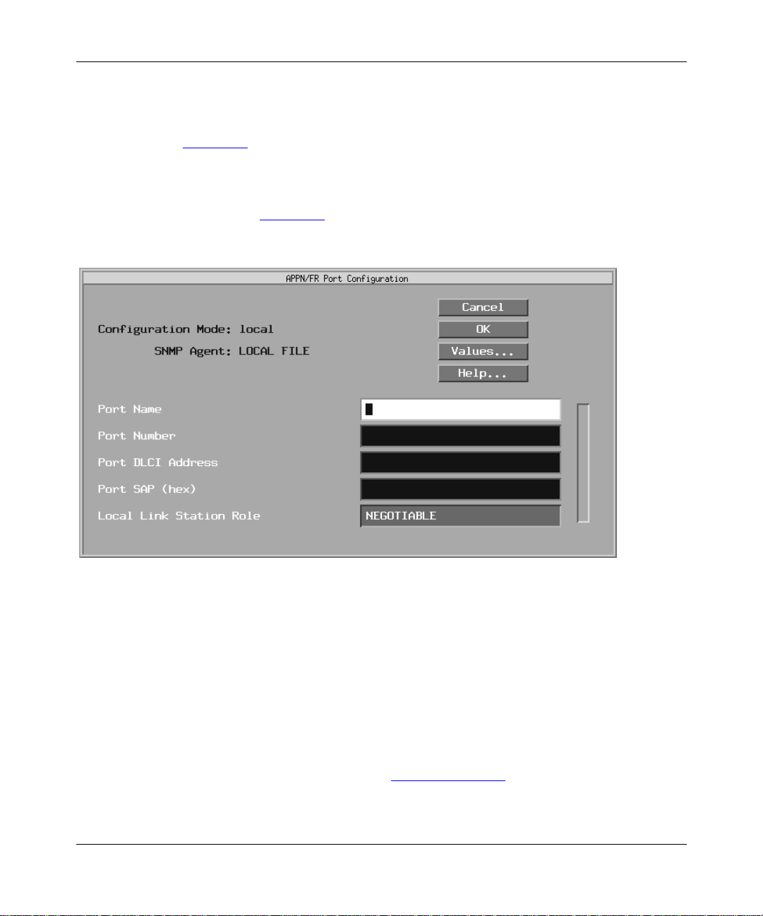
Configu ring APPN Service s
Adding Ports to an APPN Interface
To add a port to an APPN interface, display the APPN Port List window
(Figure 3-5) and proceed as follows:
Click on Add.
1.
The APPN Port Configuration or the APPN/FR Port Configuration window
appears (Figure 3-6
).
Figure 3-6. APPN/FR Port Configuration Window
Enter values f or th e P ort Name, P ort Number, Port MAC Addr e ss or P ort
2.
DLCI Address, Port SAP, and Local Link Station Role parameters.
If you are c onf igurin g SDLC, the SDLC Addres s parame ter app ears in stead of
the Port MAC Address pa ramete r. If you are configuring frame relay on an
LLC2 interface, the Port DLCI Address parameter appears.
Click on OK to save your entries to the co n figura ti on file.
3.
The APPN Port List window (refer to Figure 3-5
3-20
) reappears.
303511-A Re v 00
Page 81

Parameter: Port Name
Default: None
Options: Up to 8 alphanumeric uppercase characters
Function: Specifies the name of the newly added port.
Instructions: Enter up to 8 alphanumeric uppercase characters with no blank spaces
(leading, trailing, or e mbedded).
MIB Object ID: 1.3.6.1.4.1.18.3.5.14.1.3.1.15
Parameter : Port Numb er
Default: None
Options: Any unique 3-digit number
Function: Specifies a unique number to identify this port, if more than one port is
configured on an int erfa ce.
Instructions: Enter any 3-digit value.
Editing APPN Parameters
MIB Object ID: 1.3.6.1.4.1.18.3.5.14.1.3.1.16
Parameter: Port DLCI Address
Default: None
Options: Valid range changes based on the frame relay address length as follo ws:
Address Length Range
2 bytes 16-1007
3 bytes 1024-64511
4 bytes 131072-8257535
Function: The DLCI is the frame relay PVC identification number. The frame relay
network uses the DLCI to direct basic data flow.
Instructions: Enter a decimal number within the valid range.
MIB Object ID: 1.3.6.1.4.1.18.3.5.14.1.3.1.38
303511-A Rev 00
3-21
Page 82

Configu ring APPN Service s
Parameter : Port MAC Address
Default: None
Options: Any unique 48-bit, 12-digit hexadecimal MAC-level address
Function: Specifies a unique MAC -l evel address, DLCI (for frame relay), or SDLC
address.
Instructions: Enter a 12-digit MAC hexadecimal address in MSB non-canoni cal form
(regardless of the media), a DLCI address, or an SDLC address.
MIB Object ID: 1.3.6.1.4.1.18.3.5.14.1.3.1.38
Parameter : Port SAP (he x )
Default: None
Options: Any unique SAP 2-digit hexadecimal value, usually 04
Function: Specifies a SAP address that lets multiple applications and protocol
entities in a single comput er share a MAC address.
Instructions: Enter a 2-digit hexadecimal value.
MIB Object ID: 1.3.6.1.4.1.18.3.5.14.1.3.1.38
Parameter: SDLC Address (hex)
Default: None
Options: Any unique 2-digit hexadecimal SDLC- level address
Function: Specifies a unique SDLC address for this circuit.
Instructions: Enter a 2-digit hexadecimal address.
MIB Object ID: 1.3.6.1.4.1.18.3.5.14.1.3.1.38
3-22
303511-A Re v 00
Page 83

Parameter: Local Link Station Role
Default: Negotiable
|
Options: Negotiable
Primary | Secondary
Function: Specifies the initial role of the loc al network node when activating
adjacent link stations thr ough this port.
Negotiable means that the local network node can be either primary or
secondary and the actual rol e is dete rmined during link activation. A link
between the two nodes may require one link station to take the role of
primary link st ation a nd the ot her link sta tion to ta ke th e rol e of se condary
link station.
Instructions: Click on Values to display the options and select Negotiable, Primary, or
Secondary.
MIB Object ID: 1.3.6.1.4.1.18.3.5.14.1.3.1.8
Editing APPN Advanced Port Parameters
To edit the APPN adva nced port parameters, display the APPN Port List window
(refer to Figure 3-5) and
Editing APPN Parameters
303511-A Rev 00
Click on Advanced.
1.
The APPN Port wind ow ap pears (Figure 3-7)
.
3-23
Page 84
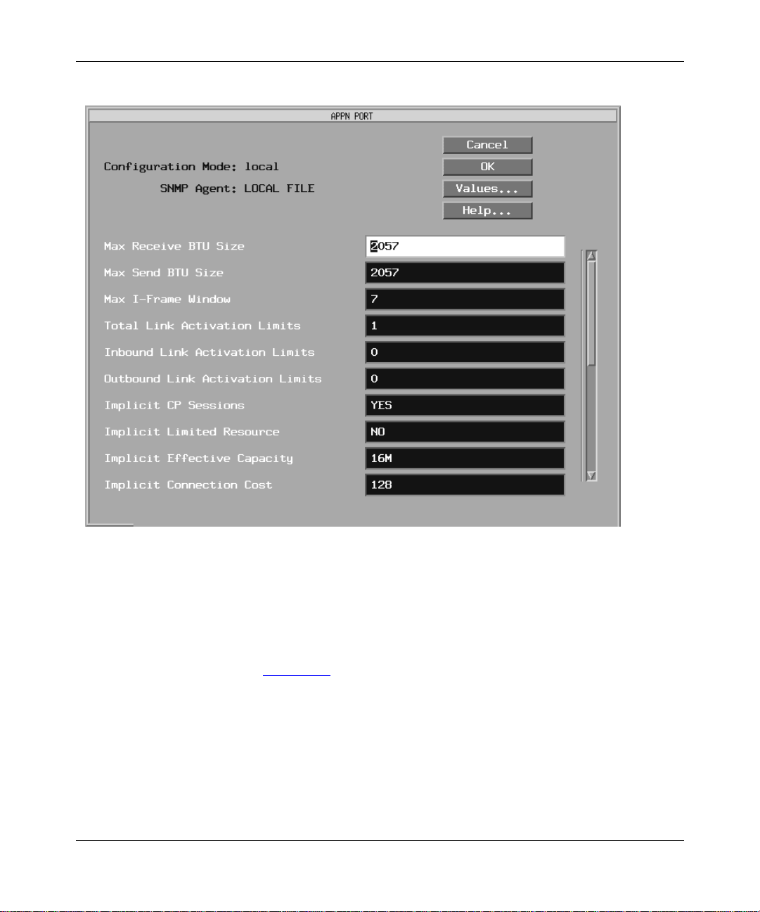
Configu ring APPN Service s
Figure 3-7. APPN Port Wind ow
Click on each parameter value that you want to change, then enter a new
2.
value.
Click on OK to save you r change s and return to the APPN Port List
3.
window (Figure 3-5).
3-24
303511-A Re v 00
Page 85

Parameter: Max Receive BTU Size
Default: 2057
Range: 256 to 4105
Function: Specifies the maximum Basic T r ansmission Unit (BTU) size that this
network node can recei v e. Each li nk station dete rmines its own maximum
BTU size based on local node definitions and exchange identification
(XID) information received from the interface and the adjacent link
station.
Instructions: Enter a number in the range 256 to 4105 that the node can handle. The
minimum setting for HPR links is 768.
MIB Object ID: 1.3.6.1.4.1.18.3.5.14.1.3.1.9
Parameter: Max Send BTU Size
Default: 2057
Range: 256 to 4105
Editing APPN Parameters
Function: Specifies the maximum Basic T r ansmission Unit (BTU) size that can be
sent over this por t. Each link station determines its own maximum send
BTU size based on local node definitions and exchange identification
(XID) information received from the interface and the adjacent link
station.
Instructions: Enter a number in the range 256 to 4105. For Etherne t networks, the
maximum send BTU size should be less than or equal to 1500. For
synchronous media, the maximum send BTU size should be less tha n or
equal to the synchronous maximum transmission unit. The minimum
setting for HPR links is 768.
MIB Object ID: 1.3.6.1.4.1.18.3.5.14.1.3.1.24
303511-A Rev 00
3-25
Page 86

Configu ring APPN Service s
Parameter : Max I-Fr am e Wind ow
Default: 7
Options: A numeric value not exceeding 127
Function: Specifies the maximum number of inf ormat ion frames (I-frames) that the
local network node can receive before it sends an acknowledgment.
Instructions: Enter a number in the range 1 to 127.
MIB Object ID: 1.3.6.1.4.1.18.3.5.14.1.3.1.10
Parameter: Total Link Activation Limits
Default: 1
Range: 0 to 256; see Table 3-1
Function: Specifies the link activation limit for this port. The value is the maximum
number of inbound and outbound link stations that the port will allow in
this configuration. The maximum value depends on the setting of the
Local Link Station Role paramete r and the type of port, as listed in Table
3-1.
Instructions: Specify a value in the range 0 to 256. The v alue must be greater than or
equal to the combined settings for the Inbound Link Activ ation Limits an d
Outbound Link Activation L imits p aram eter s .
MIB Object ID: 1.3.6.1.4.1.18.3.5.14.1.3.1.17
Parameter: Inbound Link Activation Limits
Default: 0
Range: 0 to 256; see Table 3-1
Function: Specifies the inbound link activation limit for this port. The value is the
maximum number of inbound link stations that the port will allow in this
configura tion.
Instructions: Specify a value in the range 0 to 256. This value plus the current setting
for the Outbound Link Activation Limits parameter must be less than or
equal to the current Total Link Activatio n Lim i ts parameter setting.
MIB Object ID: 1.3.6.1.4.1.18.3.5.14.1.3.1.18
3-26
303511-A Re v 00
Page 87

Parameter: Outbound Link Activation Limits
Default: 0
Range: 0 to 256; see Table 3-1
Function: Specifies the maximum outbound link activation limit for this port. The
value is the maximum number of outbound link stations that the port will
allow in this configuration.
Instructions: Specify a value in the range 0 to 255. This value plus the current setting
for the Inbound Link Activation Limits parameter must be less than or
equal to the Total Link Activat io n Lim i ts parameter setting.
MIB Object ID: 1.3.6.1.4.1.18.3.5.14.1.3.1.19
Table 3-1. Link Activation Limit Default Values
Local Link
Port Type
Station Role
Total Link
Activation
Limit
Editing APPN Parameters
Outbound
Inbound Link
Activation
Limits
Link
Activation
Limits
303511-A Rev 00
Leased Secondary 1 1 0
Leased Negotiable 1 0 0
Leased Primary 256 0 256
SA TF any 256(x+y) 128(x) 128(y)
3-27
Page 88

Configu ring APPN Service s
Parameter: Implicit CP Sessions
Default: Yes
|
Options: Yes
Function: Specifies whether CP-to-CP ses sions a re permitted for dynamic link
Instructions: Click on Values and select Yes or No.
MIB Object ID: 1.3.6.1.4.1.18.3.5.14.1.3.1.25
Parameter: Implicit Limited Resource
Default: No
Options: Yes
Function: Specifies whether dynamic lin k stat ions on this port should be defined as
Instructions: Click on Values and select Yes or No.
No
stations. Dynamic link stations are link stations that are not defined on
this port, but are activated by the adjacent node.
|
No
limited resources. A limited resource link station deactivates after the
number of sessions using the port drops to zero.
MIB Object ID: 1.3.6.1.4.1.18.3.5.14.1.3.1.26
3-28
303511-A Re v 00
Page 89

Editing APPN Parameters
Parameter: Implicit Effective Capacity
Default: 16M
Options: 1200
2400
4800
7200
9600
14400
19200
48000
56000
64000
4M
10M
16M
Maximum
Function: The Effectiv e Capacity is the hi ghest bit -transm issi on rate t hat the TG can
obtain before being conside r ed overloaded. The link bandwidth and
maximum load factor deter mine this value. TGs to dynamic link stations
on this port use this value.
Instructions: Click on Values and select a number from the list.
MIB Object ID: 1.3.6.1.4.1.18.3.5.14.1.3.1.27
Parameter: Implicit Connection Cost
Default: 128
Range: 0 to 255, inclusive
Function: Specifies the relative cost (per connect time) of using a TG to dynamic
link stations on this port . A value of 0 indicates no cost, and a value of
255 indicates maximum cost. The cost per connect time is typically based
on the applicable tariffs for the transmission facility this TG uses. An
X.25 network, for example, may have a high connection c ost for dynamic
link stations.
Instructions: Enter a number in the range 0 to 255.
MIB Object ID: 1.3.6.1.4.1.18.3.5.14.1.3.1.28
303511-A Rev 00
3-29
Page 90

Configu ring APPN Service s
Parameter: Implicit Byte Cost
Default: 128
Range: 0 to 255, inclusive
Function: Specifies the relati ve cost of transm itti ng a b yte ov e r this TG to a dyna mic
link station on this port. A value of 0 indicates no cost, and a value of 255
indicates maximum cost. An X.25 net work, for example, may ha ve a high
byte cost for dynamic link sta tions.
Instructions: Enter a number in the range 0 to 255.
MIB Object ID: 1.3.6.1.4.1.18.3.5.14.1.3.1.29
Parameter: Implicit Security
Default: Nonsecure
Options: Nonsecure
Public-Switched
Underground
Conduit
Encrypted
Guarded radiation
Maximum
Function: Specifies the security le vel of the TG to the dynamic link stations on this
port.
Instructions: Click on Values and select one of the common definitions indicated under
Options.
MIB Object ID: 1.3.6.1.4.1.18.3.5.14.1.3.1.30
3-30
303511-A Re v 00
Page 91

Parameter: Implicit Delay
Default: Negligible
Options: Negligible
Terrestrial
Packet
Long
Maximum
Function: Specifies the propaga tion del ay, or the relati ve a mount of time th at it ta kes
for a signal to trav el the length of a TG to dynamic link stations on this
port.
Instructions: Click on Values and select a common definition indicated under Options.
MIB Object ID: 1.3.6.1.4.1.18.3.5.14.1.3.1.31
Parameter: Implicit User-Defined 1
Default: 128
Range: 0 to 255
Editing APPN Parameters
Function: Specifies the first user-defined TG characteristic to a dynamic link station
on this port.
Instructions: Enter a value in the range 0 to 255.
MIB Object ID: 1.3.6.1.4.1.18.3.5.14.1.3.1.32
Parameter: Implicit User-Defined 2
Default: 128
Range: 0 to 255
Function: Specifies the second user-defined TG characteristic to a dynamic link
station on this port.
Instructions: Enter a value in the range 0 to 255.
MIB Object ID: 1.3.6.1.4.1.18.3.5.14.1.3.1.33
303511-A Rev 00
3-31
Page 92

Configu ring APPN Service s
Parameter: Implicit User-Defined 3
Default: 128
Range: 0 to 255
Function: Spec ifies the third user-defined TG charac teri s tic to a dynamic link
station on this port.
Instructions: Enter a value in the range 0 to 255.
MIB Object ID: 1.3.6.1.4.1.18.3.5.14.1.3.1.34
Parameter: DLUR Implicit LS Support
Default: Disable
|
Options: Enable
Function: Enables DLUR for implicit link stations on this port. This parameter is
ava ilable when the DLUR Support Enable/Disable par amet er is set to
Enable.
Instructions: Click on Values and select Enable or Disable.
MIB Object ID: 1.3.6.1.4.1.18.3.5.14.1.3.1.40
Disable
Parameter: HPR Implicit LS Support
Default: Enable
|
Options: Enable
Function: Enables HPR for implicit link stations on this port. This parameter is
ava ilable when the HPR Support parameter is set to Enable.
Instructions: Click on Values and select Enable or Disable.
MIB Object ID: 1.3.6.1.4.1.18.3.5.14.1.3.1.35
3-32
Disable
303511-A Re v 00
Page 93

Parameter : LLC Error Re cover y Under HPR
Default: Disable
|
Options: Enable
Disable
Function: Enables or disables LLC error recovery on implicit link stations on this
port. This parameter is available when th e global HPR Support parameter
is set to Enable, and when the HPR Implicit LS Support paramet er is se t
to Enable on this port.
Instructions: Click on Values and select Enable or Disable.
MIB Object ID: 1.3.6.1.4.1.18.3.5.14.1.3.1.36
Parameter: Implicit Link Deactivation Time
Default: 120
Range: 5 to 255
Function: Specifies the time (in seconds) before implicit link stations on this port
deac tiva t e if i t is an H PR limi ted re s ou rce. This parameter is avail able
when the Implicit Limited Resour ce is set to Yes, and when the HPR
Support and the HPR Implicit LS Support parameters are set to Enable.
Editing APPN Parameters
Instructions: Enter a value in the range 5 to 255, inclusive.
MIB Object ID: 1.3.6.1.4.1.18.3.5.14.1.3.1.37
303511-A Rev 00
3-33
Page 94

Configu ring APPN Service s
Parameter: HPR UI SAP
Default: C8
Options: Any 2-digit hexadecimal v alue
Function: Specifies the local HPR service access point address for unnumbered
information (UI) f rames on this por t. A UI frame is an LLC frame type on
which LLC does not perform link-le vel error recovery. This parameter is
ava ilable when HPR Support is set to Enable.
In base APPN/LLC2 configurations, LLC2 performs link-level recovery
by sending information frames (I-frames). If you disable link-level err or
recovery with the HPR Link-Level Error Recovery parameter, APPN
sends the HPR network layer packe ts a s UI frames, since RTP performs
the link-level error recovery on an end-to-end basis.
Instructions: Enter any 2-digit hexadecimal value. The 0x prefix is optional. For
example, the value C8 uses the 0x prefix.
MIB Object ID: 1.3.6.1.4.1.18.3.5.14.1.3.1.39
3-34
303511-A Re v 00
Page 95

Editing APPN Adjacent Link Stations
To edit APPN Adjacent Link Station parameters, begin at the Configuration
Manager window (re fer t o Figure 3-1) and
Select Protocols > APPN > Adjacent Link Stations.
1.
Editing APPN Parameters
The APPN Adjacent Link Station List windo w a ppears (Figure 3-8
).
Figure 3-8. APPN Adjacent Link Stat i on List Window
Edit those parameters you want to change.
2.
If the window appears without any adjacent link stations in the list, go to the
section “Adding Adjacent Link Stations.”
303511-A Rev 00
3-35
Page 96

Configu ring APPN Service s
Click on Apply to sa ve your changes.
3.
Click on Done to exit the window.
4.
To edit the advanced adjacent link station parameters, click on Advanced and
go to the section “Editing Adv anced Adjacent Link Station Parameters.”
Parameter: Enable/Disable
Default: Enable
Options: Enable
Function: Enables or disables the adjacent link station highlighted in the APPN
Adjacent Link Station List window.
Enable -- Initializes the selected adjacent link station. You can also use
the Enable setting to init ialize an existing adjace nt link station port that
you disabled earlier.
Disable -- Forces the adjacent link station into the “down” (inoperative)
state.
|
Disable
Instructions: Click on Values and select Enable or Disable. Select Disable to disable
the adjacent link stat ion.
Select Enable to enable or reenable the adjacent link station.
MIB Object ID: 1.3.6.1.4.1.18.3.5.14.1.4.1.2
Parameter: Port Name
Default: None
Options: Up to 8 alphanumeric uppercase characters
Function: Specifies the name of the port supporting the adjacent link station.
Instructions: Enter up to 8 alphanumeric uppercase characters with no blank spaces
(leading, trailing, or e mbedded).
MIB Object ID: 1.3.6.1.4.1.18.3.5.14.1.4.1.4
3-36
303511-A Re v 00
Page 97

Parameter: Adjacent Node Name
Default: None
Options: Any valid name with up to 17 characters in the format
<NETID>.<NAME>; NETID
characters fol lowe d b y a period, and
up to 8 characters
Function: Identifies the name of the network and the adjacent node name.
Instructions: Type to 8 characters for the network ID name, follow with a period, then
type a control point na me with u p to 8 char acters. You must use uppercase
characters only and the f irs t character must be non-numer ic. Blank spac es
(leading, trailing, and e mbedded) are not allowed in the node name. For
example, APPNNODE.CPONE is a valid entry for the Adjacent Node
Name param eter.
MIB Object ID: 1.3.6.1.4.1.18.3.5.14.1.4.1.6
Editing APPN Parameters
is the unique network name with up to 8
is the control point na me with
NAME
303511-A Rev 00
3-37
Page 98

Configu ring APPN Service s
Parameter : Adj acent Node Type
Default: LEARN
Options: LEARN
NN
EN
BACK LEVEL LEN NODE
HOST XID 3
HOST XID 0
DSPU XID
DSPU NO XID
Function: Specifies the type of adjacent link station node.
Instructions: Click on Values and select an adjacent node type, as indic at ed under
Options.
LEARN -- APPN automatically learns the type of adja cent link station.
NN -- Network Node
EN -- End Node
BA CK LEVEL LEN NODE -- Back-level low-entry networking node.
HOST XID 3 -- Host node that supports XID3 protocols; includes the
network name control ve ctor.
HOST XID 0 -- Host node that supports XID0 protocols.
DSPU XID -- Down stream physical unit (DSPU) node that supports
XID3 protocols, but does not include the network name control ve ctor.
DSPU NO XID -- Down stream physical unit (DSPU) node that does not
support XID protoc ols. This selecti on is v alid on n onswitche d ports and is
invalid on negotiable ports.
MIB Object ID: 1.3.6.1.4.1.18.3.5.14.1.4.1.23
3-38
303511-A Re v 00
Page 99

Parameter : Ena ble D LU R Support for this LS
Default: Disable
|
Options: Enable
Disable
Function: Specifies whether the adja cent link station is a PU2.0 node to be serviced
by DLUR.
Instructions: Click on Values and select Enable or Disable.
MIB Object ID: 1.3.6.1.4.1.18.3.5.14.1.4.1.28
Parameter: Primary DLUS Name
Default: None
Options: Any valid name with up to 17 characters in the format
<NETID>.<NAME>; NETID
characters fol lowe d b y a period, and
up to 8 characters
Function: Specifies the fully qualified name of the DLUS node that will serve the
PU2.0 link station.
Editing APPN Parameters
is the unique network name with up to 8
is the control point na me with
NAME
Instructions: Type up to 8 characters for the networ k ID name; follow with a period,
and then type a control point name with up to 8 characters. You must use
uppercase characters only and the first charact er must be non-numeric.
Blank spaces (leading, trailing, and embedded) are not allo wed in the
node name. For example, APPNNODE.D LUR is a valid entry for this
parameter.
MIB Object ID: 1.3.6.1.4.1.18.3.5.14.1.4.1.30
Parameter: DSPU Name
Default: None
Options: Up to 8 alphanumeric uppercase characters.
Function: Specifies the name of the do wn stream physical unit (DSPU) supported by
DLUR.
Instructions: Enter up to 8 alphanumeric uppercase characters with no blank spaces
(leading, trailing, or e mbedded). The first character must be a letter.
MIB Object ID: 1.3.6.1.4.1.18.3.5.14.1.4.1.29
303511-A Rev 00
3-39
Page 100

Configu ring APPN Service s
Parameter : Adj acent Node Block N um b er
Default: None
Options: None
Function: A unique hexadecimal value that identifies APPN in this adjacent node.
The number is the first 3 digits of the node ID.
Instructions: Accept the derived value that displays in this field.
MIB Object ID: 1.3.6.1.4.1.18.3.5.14.1.4.1.10
Parameter : Adj acent Node ID Number
Default: None
Options: Optional; if specified, a valid string of 5 hexadec imal digits (0 to 9,
A,B,C,D,E,F)
Function: Identifies the local APPN adjacent node and is p resent i n APPN ale rts and
exchange identifications (XIDs). These 5 digits are combined with the
3-digit block number to form a unique XID node identification for the
adjacent node. The APPN network node and the adjacent node exchange
node identific ations when establishing a connection.
Instructions: Enter 5 hexadecimal digits.
MIB Object ID: 1.3.6.1.4.1.18.3.5.14.1.4.1.11
3-40
303511-A Re v 00
 Loading...