

Page 1

Inst allation, Upgrades and Additions for Avaya CMC1 Media Gateways
555-233-118
Issue 10
June 2005
Page 2

Copyright 2005, Avaya Inc.
All Rights Reserved
Notice
Every effort was made to ensure that the information in this document
was complete and accurate at the time of printing. However, information
is subject to change.
Warranty
Avaya Inc. provides a limited warranty on this product. Refer to your
sales agreement to establish the terms of the limited warranty. In
addition, Avaya’s standard warranty language as well as information
regarding support for this product, while under warranty, is available
through the following Web site: http://www.avaya.com/support
.
Preventing Toll Fraud
"Toll fraud" is the unauthorized use of your telecommunications system
by an unaut horized party (for example, a person who is not a corporate
employee, agent, subcontractor, or is not working on your company's
behalf). Be aware that there may be a risk of toll fraud associated with
your system and that, if toll fraud occurs, it can result in substantial
additional charges for your telecommunications services.
Avaya Fraud Intervention
If you suspect that you are being victimized by toll fraud and you need
technical assistance or support, in the United States and Canada, call the
Technical Service Center's Toll Fraud Intervention Hotline at
1-800-643-2353.
Disclaimer
Avaya is not responsible for any modifications, additions or deletions to
the original published version of this documentation unless such
modifications, additions or deletions were performed by Avaya. Customer
and/or End User agree to indemnify and hold harmless Avaya, Avaya's
agents, servants and employees against all claims, lawsuits, demands
and judgments arising out of, or in connection with, subsequent
modifications, additions or deletions to this documentation to the extent
made by the Customer or End User.
How to Get Help
For additional support telephone numbers, go to the Avaya support Web
site: http://www.avaya.com/support
• Within the United States, click the Escalation Management
link. Then click the appropriate link for the type of support you
. If you are:
need.
• Outside the United States, click the Escalation Management
link. Then click the Internationa l Service s link that includes
telephone numbers for th e international Centers of
Excellence.
Providing Telecommunications Security
Telecommunications security (of voice, data, and/or video
communications) is the prevention of any type of intrusion to (that is,
either unauthorized or malicio us access to or use of) your company's
telecommunications equ ipm ent by some party.
Your company's "telecommunications equipment" includes both this
Avaya product and any other voice/data/video equipment that could be
accessed via this Avaya product (that is, "networked equipment").
An "outside party" is anyone who is not a corporate employee, agent,
subcontractor, or is not working on your company's behalf. Whereas, a
"malicious party" is anyone (including someone who may be otherwise
authorized) who accesses your telecommunications equipment with
either malicious or mischievous intent.
Such intrusions may be either to/through synchronous (time-multiplexed
and/or circuit-based), or asynchronous (character-, message-, or
packet-based) equipment, or interfaces for reasons of:
• Utilization (of capabilities special to the accessed equipment)
• Theft (such as, of intellectual property, financial assets, or toll
facility access)
• Eavesdropping (privacy invasions to humans)
• Mischief (troubling, but apparently innocuous, tampering)
• Harm (such as harmful tampering, data loss or alteration,
regardless of motive or intent)
Be aware that there may be a risk of unauthorized intrusions associated
with your system and/or its networked equipment. Also realize that, if
such an intrusion should occur, it could result in a variety of losses to your
company (including but not limited to, human/data privacy, intellectual
property, material assets, financial resources, labor costs, and/or legal
costs).
Responsibility for Your Company’s Telecommunications Security
The final responsibility for securing both this system and its networked
equipment rests with you - Avaya’s customer system administrator, your
telecommunications peers, and your managers. Base the fulfillment of
your responsibility on acquired knowledge and resources from a variety
of sources including but not limited to:
• Installation docume nts
• System administration documents
• Security documents
• Hardware-/software-based security tools
• Shared information between you and your peers
• Telecommunications security experts
To prevent intrusions to your telecommunications equipment, you and
your peers should carefully program and configure:
• Your Avaya-provided telecommunications systems and their
interfaces
• Your Avaya-provided software applications, as well as their
underlying hardware/software platforms and interfaces
• Any other equipment networked to your Avaya products
TCP/IP Facilities
Customers may expe rien ce dif fer ences i n prod uct per forma nce, relia bility
and security depending upon network configurations/design and
topologies, even when the product performs as warranted.
Standards Compliance
Avaya Inc. is not responsible for any radio or television interference
caused by unauthorized modifications of this equipment or the
substitution or attachment of connec ting cab les and equ i pme nt oth er
than those specified by Avaya Inc. The correction of interference caused
by such unauthorized modifications, substitution or attachment will be the
responsibility of the user. Pursuant to Part 15 of the Federal
Communications Commission (FCC) Rules, the user is cautioned that
changes or modifications not expressly approved by Avaya Inc. could
void the user’s authority to operate this equipment.
Product Safety Standards
This product complies with and conforms to the following international
Product Safety standards as applicable:
Safety of Information Technology Equipment, IEC 60950, 3rd Edition, or
IEC 60950-1, 1st Edition, including all relevant national deviations as
listed in Compliance with IEC for Electrical Equipment (IECEE) CB-96A.
Safety of Information Technology Equipment, CAN/CSA-C22.2
No. 60950-00 / UL 60950, 3rd Edition, or CAN/CSA-C22.2 No.
60950-1-03 / UL 60950-1.
Safety Requirements for Information Technology Equipment, AS/NZS
60950:2000.
One or more of the following Mexican national standards, as applicable:
NOM 001 SCFI 1993, NOM SCFI 016 1993, NOM 019 SCFI 1998.
The equipment described in this document may contain Class 1 LASER
Device(s). These devices comply with the following standards:
• EN 60825-1, Edition 1.1, 1998-01
• 21 CFR 1040.10 and CFR 1040.11.
The LASER devices used in Avaya e quipment typically operate within th e
following parameters:
Typical Center Wavelength Maximum Output Power
830 nm - 860 nm -1.5 dBm
1270 nm - 1360 nm -3.0 dBm
1540 nm - 1570 nm 5.0 dBm
Luokan 1 Laserlaite
Klass 1 Laser Apparat
Use of controls or adjustments or performance of procedures other than
those specified herein may result in hazardous radiation exposures.
Contact your Avaya representative for more laser product info rmation.
Page 3
Electromagnetic Compatibility (EMC) Standards
This product complies with and conforms to the following international
EMC standards and all relevant national deviations:
Limits and Methods of Measurement of Radio Interference of Information
Technology Equipment, CISPR 22:1997, EN55022:1998, and AS/NZS
3548.
Information Technology Equipment - Immunity Characteristics - Limits
and Methods of Measurement, CISPR 24:1997 and EN55024:1998,
including:
• Electrostatic Discharge (ESD) IEC 61000-4-2
• Radiated Immunity IEC 61000-4-3
• Electrical Fast Transient IEC 61000-4-4
• Lightning Effects IEC 61000-4-5
• Conducted Immunity IEC 61000-4-6
• Mains Frequency Magnetic Field IEC 61000-4-8
• Voltage Dips and Variations IEC 61000-4-11
Power Line Emissions, IEC 61000-3-2: Electromagnetic compatibility
(EMC) - Part 3-2: Limits - Limits for harmonic current emissions.
Power Line Emissions, IEC 61000-3-3: Electromagnetic compatibility
(EMC) - Part 3-3: Limits - Limitation of voltage changes, voltage
fluctuations and flicker in public low-voltage supply systems.
Federal Communications Commission Statement
Part 15:
Note: This e quip m en t ha s b ee n test e d a nd fo un d t o comp l y w it h
the limits for a Class A digital device, pursuant to Part 15 of the
FCC Rules. These limits are designed to provide reasonable
protection against harmful interference when the equipment is
operated in a commercial environment. This equipment
generates, uses, and can radiate radio frequency energy and, if
not installed and used in accordance w ith the instruction
manual, may cause harmful interference to radio
communications. Operation of this equipment in a residential
area is likely to cause harmful interference in which case the
user will be required to cor rect the interference at his own
expense.
Part 68: Answer-Supervision Signaling
Allowing this equipment to be operated in a manner that does not provide
proper answer-supervision signaling is in violation of Part 68 rules. This
equipment returns answer-supervision signals to the public switched
network when:
• answered by the called station,
• answered by the attendant, or
• routed to a recorded announcement that can be administered
by the customer premises equipment (CPE) user.
This equipment returns answer-supervision signals on all direct inward
dialed (DID) calls forwarded back to the public switched telephone
network. Permissible exceptions are:
• A call is unanswered.
• A busy tone is received.
• A reorder tone is received.
Avaya at test s that thi s re gis tere d eq ui pmen t is cap abl e o f pr ovid ing u ser s
access to interstate providers of operator services through the use of
access codes. Modification of this equipment by call aggregators to block
access dialing codes is a violation of the Telephone Operator Consumers
Act of 1990.
REN Number
For MCC1, SCC1, CMC1, G600, and G650 Media Gateways:
This equipment complies with Part 68 of the FCC rules. On either the
rear or inside the front cover of this equipment is a label that contains,
among other information, the FCC registration number, and ringer
equivalence number (REN) for this equipment. If requested, this
information must be provided to the telephone company.
For G350 and G700 Media Gateways:
This equipment complies with Part 68 of the FCC rules and the
requirements adopted by the ACTA. On the rear of this equipment is a
label that contains, among other information, a product identifier in the
format US:AAAEQ##TXXXX. The digits represented b y ## are the ringer
equivalence number (REN) without a decimal point (for example, 03 is a
REN of 0.3). If requested, this number must be provided to the telephone
company.
For all media gateways:
The REN is used to determine the quantity of devices that may be
connected to the telephone line. Excessive RENs on the telephone line
may result in devices not ringing in response to an incoming call. In most,
but not all areas, the sum of RENs should not exceed 5.0. To be certain
of the number of devices that may be connected to a line, as determined
by the total RENs, contact the local telephone company.
REN is not required for some types of analog or digital facilities.
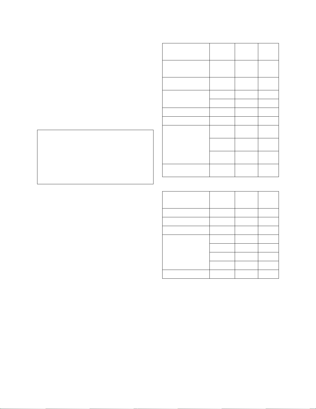
Means of Connection
Connection of this equipment to the telephone network is shown in the
following tables.
For MCC1, SCC1, CMC1, G600, and G650 Media Gateways:
Manufacturer’s Port
Identifier
FIC Code SOC/
REN/
Network
Jacks
A.S. Code
Off premises station OL13C 9.0F RJ2GX,
RJ21X,
RJ11C
DID trunk 02RV2-T 0.0B RJ2GX,
RJ21X
CO trunk 02GS2 0.3A RJ21X
02LS2 0.3A RJ21X
Tie trunk TL31M 9.0F RJ 2GX
Basic Rate Interface 02IS5 6.0F, 6.0Y RJ49C
1.544 digital interface 04DU9-BN 6.0F RJ48C,
RJ48M
04DU9-IKN 6.0F RJ48C,
RJ48M
04DU9-ISN 6.0F RJ48C,
RJ48M
120A4 channel service
04DU9-DN 6.0Y RJ48C
unit
For G350 and G700 Media Gateways:
Manufacturer’s Port
Identifier
FIC Code SOC/
REN/
A.S. Code
Network
Jacks
Ground Start CO trunk 02GS2 1.0A RJ11C
DID trunk 02RV2-T AS.0 RJ11C
Loop Start CO trunk 02LS2 0.5A RJ11C
1.544 digital interface 04DU9-BN 6 .0Y R J48C
04DU9-DN 6.0Y RJ48C
04DU9-IKN 6.0Y RJ48C
04DU9-ISN 6.0Y RJ48C
Basic Rate Interface 02IS5 6.0F RJ49C
For all media gateways:
If the terminal equipment (for example, the media server or media
gateway) causes harm to the telephone network, the telephone company
will notify you in advance that temporary discontinuance of service may
be required. But if advance notice is not practical, the telephone
company will notify the customer as soon as possible. Also, you will be
advised of your right to file a complaint with the FCC if you believe it is
necessary.
The telephone company may make changes in its facilities, equipment,
operations or procedures that could affect the operation of the
equipment. If this happens, the telephone company will provide advance
notice in order for you to make necessary modifications to maintain
uninterrupted service.
If trouble is experienced with this equipment, for repair or warranty
information, please contact the Technical Service Center at
1-800-242- 2121 or contact your local Avaya representative. If the
equipment is causing harm to the telephone network, the telephone
company may request that you disconnect the equipment until the
problem is resolved.
Page 4

A plug and jack used to connect this equipment to the premises wiring
and telephone network must comply with the applicable FCC Part 68
rules and requirements adopted by the ACTA. A compliant telephone
cord and modular plug is provided with this product. It is designed to be
connected to a compatible modular jack that is also compliant. It is
recommended that repairs be performed by Avaya certified technicians.
The equipment cannot be used on public coin phone service provided by
the telephone company. Connection to party line service is subject to
state tariffs. Contact the state public utility commission, public service
commission or corporation commis sion for information.
This equipment, if it uses a telephone receiver, is hearing aid compatible.
Canadian Department of Communic ations (DOC) Interference
Information
This Class A digital apparatus complies with Canadian ICES-003.
Cet appareil numérique de la classe A est conforme à la norme
NMB-003 du Canada.
This equipment meets the applicable Industry Canada Terminal
Equipment Technical Specifications. This is confirmed by the registration
number. The abbreviation, IC, before the registration number signifies
that registration was performed based on a Declaration of Conformity
indicating that Industry Canada technical specifications were met. It does
not imply that Industry Canada approved the equipment.
Installation and Repairs
Before installing this equipment, users should ensure that it is
permissible to be connected to the facilities of the local
telecommunications company. The equipment must also be installed
using an acceptable method of connection. The customer should be
aware that compliance with the above conditions may not prevent
degradation of service in some situations.
Repairs to certified equipment should be coordinated by a representative
designated by the supplier. Any repairs or alterations made by the user to
this equipment, or equipment malfunctions, may give the
telecommunications company cause to request the user to disconnect
the equipment.
Declarations of Conformity
United States FCC Part 68 Supplier’s Declaration of Conformity (SDoC)
Avaya Inc. in the United States of America hereby certifies that the
equipment described in this document and bearing a TIA TSB-168 label
identification number complies with the FCC’s Rules and Regulations 47
CFR Part 68, and the Administrative Council on Terminal Attachments
(ACTA) adopted technical criteria.
Avaya further asserts that Avaya handset-equipped terminal equipment
described in this document complies with Paragraph 68.316 of the FCC
Rules and Regulations defining Hearing Aid Compatibility and is deemed
compatible with hearing aids.
Copies of SDoCs signed by the Responsible Party in the U. S. can be
obtained by contacting your local sales representative and are available
on the following Web site: http://www.avaya.com/support
All Avaya media servers and media gateways are compliant with FCC
Part 68, but many have been registered with the FCC before the SDoC
process was available. A list of all Avaya registered products may be
found at: http://www.part68.org
manufacturer.
European Union Declarations of Conformity
by conducting a search using "Avaya" as
.
To order copies of this and other documents:
Call: Avaya Publications Center
Voice 1.800.457.1235 or 1.207.866.6701
FAX 1.800.457.1764 or 1.207.626.72 69
Write: Globalware Solutions
200 Ward Hill Avenue
Haverhill, MA 01835 USA
Attention: Avaya Account Management
E-mail: totalware@gwsmail.com
For the most current versions of documentation, go to the Avaya support
Web site: http://www.avaya.com/support
.
Avaya Inc. declares that the equipment specified in this document
bearing the "CE" (Conformité Europeénne) mark conforms to the
European Union Radio and Telecommunications Terminal Equipment
Directive (1999/5/EC), including the Electromagnetic Compatibility
Directive (89/336/EEC ) and Low Voltage Directive (73/23/ EEC ) .
Copies of these Declarations of Conform ity (DoCs) can be obtaine d by
contacting your local sales representative and are available on the
following Web site: http://www.avaya.com/support
Japan
This is a Class A product based on the standard of the Voluntary Control
Council for Interference by Information Technology Equipment (VCCI). If
this equipment is used in a domestic environment, radio disturbance may
occur, in which case, the user may be required to take corrective actions.
.
Page 5

Contents
About This Book. . . . . . . . . . . . . . . . . . . . . . . . . . . . . . . 19
Conventions used in this book . . . . . . . . . . . . . . . . . . . . . . . . . . . . 19
General . . . . . . . . . . . . . . . . . . . . . . . . . . . . . . . . . . . . . . . 19
Typographic . . . . . . . . . . . . . . . . . . . . . . . . . . . . . . . . . . . . 19
Admonishments . . . . . . . . . . . . . . . . . . . . . . . . . . . . . . . . . . 20
Physical dimensions . . . . . . . . . . . . . . . . . . . . . . . . . . . . . . . 21
Trademarks. . . . . . . . . . . . . . . . . . . . . . . . . . . . . . . . . . . . . . . 21
How to get this book. . . . . . . . . . . . . . . . . . . . . . . . . . . . . . . . . . 21
On the Web. . . . . . . . . . . . . . . . . . . . . . . . . . . . . . . . . . . . . 21
Non-Web . . . . . . . . . . . . . . . . . . . . . . . . . . . . . . . . . . . . . . 22
Where to get additional help . . . . . . . . . . . . . . . . . . . . . . . . . . . . . 22
Tell us what you think . . . . . . . . . . . . . . . . . . . . . . . . . . . . . . . . . 23
Security Issues. . . . . . . . . . . . . . . . . . . . . . . . . . . . . . . . . . . . . 24
Antistatic Protection. . . . . . . . . . . . . . . . . . . . . . . . . . . . . . . . . . 24
Remove/Install circuit packs . . . . . . . . . . . . . . . . . . . . . . . . . . . . . 24
Chapter 1: Installing and Cabling the Cabinets . . . . . . . . . . . . . . 25
Read This First. . . . . . . . . . . . . . . . . . . . . . . . . . . . . . . . . . . . . 25
License File . . . . . . . . . . . . . . . . . . . . . . . . . . . . . . . . . . . . 25
Pre-installation checklist . . . . . . . . . . . . . . . . . . . . . . . . . . . . . 25
Go to the RFA website. . . . . . . . . . . . . . . . . . . . . . . . . . . . . 27
No direct connection . . . . . . . . . . . . . . . . . . . . . . . . . . . . . 27
If you have problems with RFA . . . . . . . . . . . . . . . . . . . . . . . . 28
Check Customer’s Order . . . . . . . . . . . . . . . . . . . . . . . . . . . . . . . 29
Correcting Shipping Errors . . . . . . . . . . . . . . . . . . . . . . . . . . . . . . 29
Unpack and Inspect . . . . . . . . . . . . . . . . . . . . . . . . . . . . . . . . . . 29
Comcodes for CMC1. . . . . . . . . . . . . . . . . . . . . . . . . . . . . . . . . . 31
Install the System Cabinets . . . . . . . . . . . . . . . . . . . . . . . . . . . . . . 34
Set the Carrier Address ID — All Cabinets. . . . . . . . . . . . . . . . . . . . 34
Floor-Mount the Cabinet . . . . . . . . . . . . . . . . . . . . . . . . . . . . . 35
Wall-Mount the Cabinets . . . . . . . . . . . . . . . . . . . . . . . . . . . . . 36
Install Plywood Backing onto Wall . . . . . . . . . . . . . . . . . . . . . . 36
Install Cabinet A — Wall-Mount. . . . . . . . . . . . . . . . . . . . . . . . . . 37
Install 2 or 3 Vertically Mounted Cabinets . . . . . . . . . . . . . . . . . . 39
Install 2 Cabinets Vertically and 1 Cabinet Horizontally . . . . . . . . . . 40
Install Left and Right Panels — Wall-Mount . . . . . . . . . . . . . . . . . . . 41
Issue 10 June 2005 5
Page 6

Contents
AC Power and Ground. . . . . . . . . . . . . . . . . . . . . . . . . . . . . . . . . 42
Check AC Power . . . . . . . . . . . . . . . . . . . . . . . . . . . . . . . . 42
Approved Grounds . . . . . . . . . . . . . . . . . . . . . . . . . . . . . . 43
Uninterruptible Power Supply . . . . . . . . . . . . . . . . . . . . . . . . . . 44
CMC Power Switch . . . . . . . . . . . . . . . . . . . . . . . . . . . . . . . . 45
Connect Cabinet Grounds and Other Grounds . . . . . . . . . . . . . . . . . 46
Install the Ground Block. . . . . . . . . . . . . . . . . . . . . . . . . . . . 46
Install Coupled Bonding Conductor . . . . . . . . . . . . . . . . . . . . . . . 48
Connect and Route Cabinet AC Power Cords . . . . . . . . . . . . . . . . . . 48
Cable the System . . . . . . . . . . . . . . . . . . . . . . . . . . . . . . . . . . . 50
Install Processor Interface Cable — Cabinet A
Only and TDM/LAN Bus Terminator. . . . . . . . . . . . . . . . . . . . . . . 50
Cable the Multi-Cabinet System — Wall-Mount . . . . . . . . . . . . . . . . . 51
Vertically Mounted System . . . . . . . . . . . . . . . . . . . . . . . . . . 51
Vertically and Horizontally Mounted System . . . . . . . . . . . . . . . . 52
Install Main Distribution Frame
(MDF) and External Modem . . . . . . . . . . . . . . . . . . . . . . . . . . . . . 53
Install the MDF . . . . . . . . . . . . . . . . . . . . . . . . . . . . . . . . . . . 53
Bottom-mounted MDF with Modem. . . . . . . . . . . . . . . . . . . . . . 53
Top-Mounted MDF . . . . . . . . . . . . . . . . . . . . . . . . . . . . . . . 55
Dual MDFs . . . . . . . . . . . . . . . . . . . . . . . . . . . . . . . . . . . 56
Install the External Modem . . . . . . . . . . . . . . . . . . . . . . . . . . . . 58
Install Equipment Room Hardware . . . . . . . . . . . . . . . . . . . . . . . . . . 58
Cross-Connect the Cabinets to the MDF. . . . . . . . . . . . . . . . . . . . . 58
Circuit Pack Installation. . . . . . . . . . . . . . . . . . . . . . . . . . . . . . 59
Circuit Pack Slot Loading . . . . . . . . . . . . . . . . . . . . . . . . . . . 59
Off-Premises Circuit Protection . . . . . . . . . . . . . . . . . . . . . . . . . 64
Install Sneak Fuse Panels. . . . . . . . . . . . . . . . . . . . . . . . . . . . . 64
Label the Main Distribution Frame . . . . . . . . . . . . . . . . . . . . . . . . 67
Set Up System Access . . . . . . . . . . . . . . . . . . . . . . . . . . . . . . . . 68
Starting Terminal Emulation . . . . . . . . . . . . . . . . . . . . . . . . . . . 68
Connecting a PC . . . . . . . . . . . . . . . . . . . . . . . . . . . . . . . . . . 68
Direct connection . . . . . . . . . . . . . . . . . . . . . . . . . . . . . . . 69
Remote connection . . . . . . . . . . . . . . . . . . . . . . . . . . . . . . 69
Set Ringing Option . . . . . . . . . . . . . . . . . . . . . . . . . . . . . . . . . . 76
Activate and Administer the System . . . . . . . . . . . . . . . . . . . . . . . . . 77
Power Up System . . . . . . . . . . . . . . . . . . . . . . . . . . . . . . . . . 77
Single Cabinet Installations . . . . . . . . . . . . . . . . . . . . . . . . . . 77
Multi-Cabinet Installations . . . . . . . . . . . . . . . . . . . . . . . . . . 77
Deliver or Install the License File. . . . . . . . . . . . . . . . . . . . . . . . . 77
6 Installation, Upgrades and Additions for Avaya CMC1 Media Gateways
Page 7

System Administration . . . . . . . . . . . . . . . . . . . . . . . . . . . . . . 78
Log into the System . . . . . . . . . . . . . . . . . . . . . . . . . . . . . . 78
Check System Status . . . . . . . . . . . . . . . . . . . . . . . . . . . . . 78
Check Customer Options . . . . . . . . . . . . . . . . . . . . . . . . . . . 78
Set Country Options. . . . . . . . . . . . . . . . . . . . . . . . . . . . . . 79
Change Craft Password . . . . . . . . . . . . . . . . . . . . . . . . . . . . 81
Set Daylight Savings Rules . . . . . . . . . . . . . . . . . . . . . . . . . . 82
Set Date and Time . . . . . . . . . . . . . . . . . . . . . . . . . . . . . . . 83
Circuit Pack Administration. . . . . . . . . . . . . . . . . . . . . . . . . . 85
Set System Maintenance Parameters . . . . . . . . . . . . . . . . . . . . 85
Administer the Attendant Console . . . . . . . . . . . . . . . . . . . . . . 85
Save Translations . . . . . . . . . . . . . . . . . . . . . . . . . . . . . . . 86
Add Translations. . . . . . . . . . . . . . . . . . . . . . . . . . . . . . . . 86
Install and Wire Telephones and Trunks . . . . . . . . . . . . . . . . . . . . . . . 86
DCP, analog, and ISDN-BRI . . . . . . . . . . . . . . . . . . . . . . . . . . . . 87
Analog Station or 2-Wire Digital Station Example. . . . . . . . . . . . . . 88
Analog Tie Trunk Example . . . . . . . . . . . . . . . . . . . . . . . . . . 88
Digital Tie Trunk Example. . . . . . . . . . . . . . . . . . . . . . . . . . . 89
DS1 Tie Trunk Example . . . . . . . . . . . . . . . . . . . . . . . . . . . . 90
Collocated DS1 Tie Trunks . . . . . . . . . . . . . . . . . . . . . . . . . . 90
3-Pair and 4-Pair Modularity. . . . . . . . . . . . . . . . . . . . . . . . . . 91
Install Attendant Console — Optional . . . . . . . . . . . . . . . . . . . . . . 92
Hard-Wire Bridging . . . . . . . . . . . . . . . . . . . . . . . . . . . . . . 92
Dual Wiring of 2-Wire and 4-Wire Endpoints. . . . . . . . . . . . . . . . . 93
Install 26B1 Selector Console — Optional . . . . . . . . . . . . . . . . . . . . 93
Administer IP Stations and Trunks. . . . . . . . . . . . . . . . . . . . . . . . 93
Install and Wire Telephone Power Supplies . . . . . . . . . . . . . . . . . . . . 93
Typical Adjunct Power Connections . . . . . . . . . . . . . . . . . . . . . . . 94
Adjunct Power Adapter . . . . . . . . . . . . . . . . . . . . . . . . . . . . 94
Adjunct Power Connections End-to-End. . . . . . . . . . . . . . . . . . . 94
Auxiliary Power for an Attendant Console. . . . . . . . . . . . . . . . . . 95
1145B2 Power Supply . . . . . . . . . . . . . . . . . . . . . . . . . . . . . . 96
Important Warning for 1145B2 Power Supply . . . . . . . . . . . . . . . 97
Mounting the 1145B2/1146B2 Power Supply. . . . . . . . . . . . . . . . . 98
Install the Wall-Mounting Plates . . . . . . . . . . . . . . . . . . . . . . . 101
Mount the 1146B2 Power Distribution Unit . . . . . . . . . . . . . . . . . 101
Install the Battery Mounting/Wiring . . . . . . . . . . . . . . . . . . . . . 102
Install the Expanded Power Distribution Unit . . . . . . . . . . . . . . . 102
Power Up and Test the Power Supply . . . . . . . . . . . . . . . . . . . . 103
Contents
Issue 10 June 2005 7
Page 8

Contents
Wire the 1146B2 Power Distribution Unit . . . . . . . . . . . . . . . . . . 104
Reset LEDs on Power Distribution Unit . . . . . . . . . . . . . . . . . . . 106
1152A1 Mid-Span Power Distribution Unit. . . . . . . . . . . . . . . . . . . . 106
Important Safety Instructions . . . . . . . . . . . . . . . . . . . . . . . . . 106
Using the 1152A1 PDU. . . . . . . . . . . . . . . . . . . . . . . . . . . . . 107
Connect the 1152A1 PDU . . . . . . . . . . . . . . . . . . . . . . . . . . . 108
Connect the Cables . . . . . . . . . . . . . . . . . . . . . . . . . . . . . . 108
P333T-PWR Power over Ethernet Stackable Switch . . . . . . . . . . . . . . 110
P333T-PWR switch Important Safety Instructions. . . . . . . . . . . . . . 110
Using the P333T-PWR switch . . . . . . . . . . . . . . . . . . . . . . . . . 111
Connect the P333T-PWR switch . . . . . . . . . . . . . . . . . . . . . . . 111
1151B1 and 1151B2 Power Supplies . . . . . . . . . . . . . . . . . . . . . . 113
Important Safety Instructions for 1151B1 and
1151B2 Power Supplies . . . . . . . . . . . . . . . . . . . . . . . . . . . 113
Using 1151B1 and 1151B2 Power Supplies . . . . . . . . . . . . . . . . . 114
Connect the 1151B1 or 1151B2 Power Supplies . . . . . . . . . . . . . . 114
Connect External Alarms and Auxiliary Connecti ons. . . . . . . . . . . . . . . . 115
Alarm Input. . . . . . . . . . . . . . . . . . . . . . . . . . . . . . . . . . . 115
Alarm Output . . . . . . . . . . . . . . . . . . . . . . . . . . . . . . . . . . 116
Emergency Transfer and Auxiliary Power . . . . . . . . . . . . . . . . . . 116
Telephone Pin Designations . . . . . . . . . . . . . . . . . . . . . . . . . . . . . 117
CAMA/E911 Installation . . . . . . . . . . . . . . . . . . . . . . . . . . . . . . . . 118
Configuration . . . . . . . . . . . . . . . . . . . . . . . . . . . . . . . . . . . 118
Hardware Setup . . . . . . . . . . . . . . . . . . . . . . . . . . . . . . . . . . 118
Administration Setup . . . . . . . . . . . . . . . . . . . . . . . . . . . . . . . 118
Install the BRI Terminating Resistor . . . . . . . . . . . . . . . . . . . . . . . . . 126
Terminating Resistor Adapter . . . . . . . . . . . . . . . . . . . . . . . . . . 127
Closet Mounted (110RA1-12) . . . . . . . . . . . . . . . . . . . . . . . . . . . 128
Install Multi-point Adapters . . . . . . . . . . . . . . . . . . . . . . . . . . . . . . 129
BR851-B Adapter (T-Adapter). . . . . . . . . . . . . . . . . . . . . . . . . . . 130
367A Adapter. . . . . . . . . . . . . . . . . . . . . . . . . . . . . . . . . . . . 131
Basic Multi-point Installation Distances . . . . . . . . . . . . . . . . . . . . . 132
Install Off -Premises Station Wiri ng. . . . . . . . . . . . . . . . . . . . . . . . . . 133
Install Off-Premises or Out-of-Building Stations . . . . . . . . . . . . . . 133
Analog Off-Premises Stations . . . . . . . . . . . . . . . . . . . . . . . . 133
Circuit Protectors . . . . . . . . . . . . . . . . . . . . . . . . . . . . . . . 135
Digital Out-of-Building Telephones. . . . . . . . . . . . . . . . . . . . . . 136
8 Installation, Upgrades and Additions for Avaya CMC1 Media Gateways
Page 9

Install Emergency Transfer Unit and
Associated Telephones . . . . . . . . . . . . . . . . . . . . . . . . . . . . . . . 138
Install the Emergency Transfer Panel . . . . . . . . . . . . . . . . . . . . . . 138
Install Telephone for Power Transfer Unit . . . . . . . . . . . . . . . . . . 144
Connect Modem to Telephone Network . . . . . . . . . . . . . . . . . . . . . . . 146
External Modem Option Settings . . . . . . . . . . . . . . . . . . . . . . . . . 147
Chapter 2: Completing Installation and Cable Pinouts . . . . . . . . . . 151
System Administration . . . . . . . . . . . . . . . . . . . . . . . . . . . . . . . . 151
Alarms and Reporting . . . . . . . . . . . . . . . . . . . . . . . . . . . . . . . . . 151
Resolve Alarms . . . . . . . . . . . . . . . . . . . . . . . . . . . . . . . . . . 151
Enable Alarm Origination to INADS . . . . . . . . . . . . . . . . . . . . . . . 152
Register the Switch for Maintenance. . . . . . . . . . . . . . . . . . . . . . . 152
Place a Test Call . . . . . . . . . . . . . . . . . . . . . . . . . . . . . . . . . . . . 156
Set Neon Voltage — Ring Ping . . . . . . . . . . . . . . . . . . . . . . . . . . . . 156
Installation Completion . . . . . . . . . . . . . . . . . . . . . . . . . . . . . . . . 157
Power Supply LED Indications . . . . . . . . . . . . . . . . . . . . . . . . . . . . 157
TN760E Tie Trunk Option Settings . . . . . . . . . . . . . . . . . . . . . . . . . . 158
Contents
TN464HP and TN2464CP Option Settings . . . . . . . . . . . . . . . . . . . . . . 160
Connector and Cable Diagrams — Pinout Charts. . . . . . . . . . . . . . . . . . 162
Processor Interface Cable Pinout . . . . . . . . . . . . . . . . . . . . . . . . 165
Chapter 3: Upgrading R6csi/R7csi/R8csi to
Avaya Communication Manager on an
Avaya DEFINITY Server CSI . . . . . . . . . . . . . . . . . . 177
Read This First. . . . . . . . . . . . . . . . . . . . . . . . . . . . . . . . . . . . . 177
License File . . . . . . . . . . . . . . . . . . . . . . . . . . . . . . . . . . . . 177
7-digit dial plan expansion . . . . . . . . . . . . . . . . . . . . . . . . . . . . 178
Call Management System . . . . . . . . . . . . . . . . . . . . . . . . . . . . . 178
Service Interruption . . . . . . . . . . . . . . . . . . . . . . . . . . . . . . . . 178
Contact Network Technicians. . . . . . . . . . . . . . . . . . . . . . . . . . . 178
Translation Card Upgrade Procedures. . . . . . . . . . . . . . . . . . . . . . 179
Usable Circuit Packs . . . . . . . . . . . . . . . . . . . . . . . . . . . . . . . 179
Software Upgrade . . . . . . . . . . . . . . . . . . . . . . . . . . . . . . . . . 179
Task Table . . . . . . . . . . . . . . . . . . . . . . . . . . . . . . . . . . . . . . . 180
Pre-upgrade checklist . . . . . . . . . . . . . . . . . . . . . . . . . . . . . . . 181
Go to the RFA Website . . . . . . . . . . . . . . . . . . . . . . . . . . . . 183
Have direct connection . . . . . . . . . . . . . . . . . . . . . . . . . . . . 183
No direct connection . . . . . . . . . . . . . . . . . . . . . . . . . . . . . 183
Issue 10 June 2005 9
Page 10

Contents
If you have problems with RFA . . . . . . . . . . . . . . . . . . . . . . . . 184
Pre-upgrade administrati on changes . . . . . . . . . . . . . . . . . . . . . . 185
Remove Print Messages Feature Access Code . . . . . . . . . . . . . . . 185
Remove print-msgs buttons . . . . . . . . . . . . . . . . . . . . . . . . . 186
Remove MSA node names . . . . . . . . . . . . . . . . . . . . . . . . . . 188
Remove MSA processor channels . . . . . . . . . . . . . . . . . . . . . . 188
Remove MET station administration . . . . . . . . . . . . . . . . . . . . . 189
Check SPE . . . . . . . . . . . . . . . . . . . . . . . . . . . . . . . . . . . . . 189
Verify Software Version . . . . . . . . . . . . . . . . . . . . . . . . . . . . . . 189
Verify System Status . . . . . . . . . . . . . . . . . . . . . . . . . . . . . . . 190
Disable Scheduled Maintenance and Alarm
Origination to INADS. . . . . . . . . . . . . . . . . . . . . . . . . . . . . . . 190
Check Link Status . . . . . . . . . . . . . . . . . . . . . . . . . . . . . . . . . 191
Save Translations . . . . . . . . . . . . . . . . . . . . . . . . . . . . . . . . . 191
Save Announcements (if necessary). . . . . . . . . . . . . . . . . . . . . . . 192
Shut Down DEFINITY AUDIX System (if necessary). . . . . . . . . . . . . . . 192
Replace Circuit Packs . . . . . . . . . . . . . . . . . . . . . . . . . . . . . . . 192
Install the License File. . . . . . . . . . . . . . . . . . . . . . . . . . . . . . . 193
Pre-installation . . . . . . . . . . . . . . . . . . . . . . . . . . . . . . . . . 193
Installation (direct connection) . . . . . . . . . . . . . . . . . . . . . . . . 194
Installation (no direct connect ion) . . . . . . . . . . . . . . . . . . . . . . 194
Display Memory-Configuration . . . . . . . . . . . . . . . . . . . . . . . . . . 194
Set Daylight Savings Rules . . . . . . . . . . . . . . . . . . . . . . . . . . . . 195
Verify the Upgrade . . . . . . . . . . . . . . . . . . . . . . . . . . . . . . . . . 196
Enable Scheduled Maintenance . . . . . . . . . . . . . . . . . . . . . . . . . 196
Enable Alarm Origination to INADS . . . . . . . . . . . . . . . . . . . . . . . 197
Register the Switch for Maintenance. . . . . . . . . . . . . . . . . . . . . . . 197
Check Customer Options . . . . . . . . . . . . . . . . . . . . . . . . . . . . . 201
Check Link Status . . . . . . . . . . . . . . . . . . . . . . . . . . . . . . . . . 201
Power Up DEFINITY AUDIX System . . . . . . . . . . . . . . . . . . . . . . . 201
Resolve Alarms . . . . . . . . . . . . . . . . . . . . . . . . . . . . . . . . . . 201
Restore Announcements (if necessary) . . . . . . . . . . . . . . . . . . . . . 201
Check SPE . . . . . . . . . . . . . . . . . . . . . . . . . . . . . . . . . . . . . 202
Install translation card. . . . . . . . . . . . . . . . . . . . . . . . . . . . . . . 202
Save Translations (post-upgrade) . . . . . . . . . . . . . . . . . . . . . . . . 202
Save Announcements (if necessary—
post-upgrade). . . . . . . . . . . . . . . . . . . . . . . . . . . . . . . . . . . 202
Return Equipment . . . . . . . . . . . . . . . . . . . . . . . . . . . . . . . . . 202
DEFINITY AUDIX Power Procedures . . . . . . . . . . . . . . . . . . . . . . . . . 203
Power Down the AUDIX System . . . . . . . . . . . . . . . . . . . . . . . 203
Power Up the AUDIX System . . . . . . . . . . . . . . . . . . . . . . . . . 203
10 Installation, Upgrades and Additions for Avaya CMC1 Media Gateways
Page 11

Chapter 4: Upgrading R9csi/R10csi/Communication
Manager 1.x/2.x to Avaya Communication Manager
2.2 on an Avaya DEFINITY Server CSI . . . . . . . . . . . . 205
Read this first . . . . . . . . . . . . . . . . . . . . . . . . . . . . . . . . . . . . . 205
License File . . . . . . . . . . . . . . . . . . . . . . . . . . . . . . . . . . . . 205
7-digit dial plan expansion . . . . . . . . . . . . . . . . . . . . . . . . . . . . 205
Service interruption . . . . . . . . . . . . . . . . . . . . . . . . . . . . . . . . 206
Call Management System (CMS) . . . . . . . . . . . . . . . . . . . . . . . . . 206
Software compatibility. . . . . . . . . . . . . . . . . . . . . . . . . . . . . . . 206
Usable circuit packs. . . . . . . . . . . . . . . . . . . . . . . . . . . . . . . . 207
Wireless systems . . . . . . . . . . . . . . . . . . . . . . . . . . . . . . . . . 207
Antistatic protection . . . . . . . . . . . . . . . . . . . . . . . . . . . . . . . . 207
Task table. . . . . . . . . . . . . . . . . . . . . . . . . . . . . . . . . . . . . . . . 207
Pre-upgrade checklist . . . . . . . . . . . . . . . . . . . . . . . . . . . . . . . 209
Go to the RFA website. . . . . . . . . . . . . . . . . . . . . . . . . . . . . . . 211
Have direct connection . . . . . . . . . . . . . . . . . . . . . . . . . . . . 211
No direct connection . . . . . . . . . . . . . . . . . . . . . . . . . . . . . 211
If you have problems with RFA . . . . . . . . . . . . . . . . . . . . . . . . 212
Pre-upgrade administrati on changes . . . . . . . . . . . . . . . . . . . . . . 213
Remove Print Messages Feature Access Code . . . . . . . . . . . . . . . 214
Remove print-msgs buttons . . . . . . . . . . . . . . . . . . . . . . . . . 214
Remove MSA node names . . . . . . . . . . . . . . . . . . . . . . . . . . 216
Remove MSA processor channels . . . . . . . . . . . . . . . . . . . . . . 216
Remove MET station administration . . . . . . . . . . . . . . . . . . . . . 217
Check SPE . . . . . . . . . . . . . . . . . . . . . . . . . . . . . . . . . . . . . 218
Verify version . . . . . . . . . . . . . . . . . . . . . . . . . . . . . . . . . . . 218
Verify system status . . . . . . . . . . . . . . . . . . . . . . . . . . . . . . . . 218
Disable scheduled maintenance
and alarm origination . . . . . . . . . . . . . . . . . . . . . . . . . . . . . . 219
Check link status . . . . . . . . . . . . . . . . . . . . . . . . . . . . . . . . . 220
Save translations . . . . . . . . . . . . . . . . . . . . . . . . . . . . . . . . . 220
Save announcements (if necessary) . . . . . . . . . . . . . . . . . . . . . . . 221
Upgrade the software . . . . . . . . . . . . . . . . . . . . . . . . . . . . . . . 221
Install the License File. . . . . . . . . . . . . . . . . . . . . . . . . . . . . . . 222
Pre-installation . . . . . . . . . . . . . . . . . . . . . . . . . . . . . . . . . 222
Installation (direct connection) . . . . . . . . . . . . . . . . . . . . . . . . 222
Installation (no direct connect ion) . . . . . . . . . . . . . . . . . . . . . . 223
Administer no-license/emergency numbers. . . . . . . . . . . . . . . . . . . 223
Set daylight savings rules. . . . . . . . . . . . . . . . . . . . . . . . . . . . . 223
Verify the upgrade . . . . . . . . . . . . . . . . . . . . . . . . . . . . . . . . . 224
Check link status . . . . . . . . . . . . . . . . . . . . . . . . . . . . . . . . . 225
Contents
Issue 10 June 2005 11
Page 12

Contents
Enable scheduled maintenance . . . . . . . . . . . . . . . . . . . . . . . . . 226
Register the switch for maintenance. . . . . . . . . . . . . . . . . . . . . . . 226
Resolve alarms. . . . . . . . . . . . . . . . . . . . . . . . . . . . . . . . . . . 229
Restore busyouts . . . . . . . . . . . . . . . . . . . . . . . . . . . . . . . . . 229
Restore announcements . . . . . . . . . . . . . . . . . . . . . . . . . . . . . 230
Check SPE . . . . . . . . . . . . . . . . . . . . . . . . . . . . . . . . . . . . . 230
Save translations (post-upgrade). . . . . . . . . . . . . . . . . . . . . . . . . 230
Save announcements (post-upgrade) . . . . . . . . . . . . . . . . . . . . . . 230
Return equipment . . . . . . . . . . . . . . . . . . . . . . . . . . . . . . . . . 230
Chapter 5: Adding or Removing Hardware . . . . . . . . . . . . . . . . 231
Add Circuit Packs . . . . . . . . . . . . . . . . . . . . . . . . . . . . . . . . . . . 231
Upgrade Firmware on Programmable Circuit Packs . . . . . . . . . . . . . . . . 231
Self and C-LAN-distributed download procedure . . . . . . . . . . . . . . . 232
Prepare for download . . . . . . . . . . . . . . . . . . . . . . . . . . 234
Upload image file from the Web to staging area . . . . . . . . . . . . . 238
FTP the image file to source . . . . . . . . . . . . . . . . . . . . . . . . 239
Schedule a download to target(s) . . . . . . . . . . . . . . . . . . . . . 239
Monitor download progress . . . . . . . . . . . . . . . . . . . . . . . . 243
Reseat VAL circuit pack . . . . . . . . . . . . . . . . . . . . . . . . . . . 245
Disable file system . . . . . . . . . . . . . . . . . . . . . . . . . . . . . 245
Troubleshooting firmware downloads . . . . . . . . . . . . . . . . . . . . . 246
Aborting a firmware download . . . . . . . . . . . . . . . . . . . . . . . 246
Testing firmware download . . . . . . . . . . . . . . . . . . . . . . . . . 246
Backing out of a firmware download . . . . . . . . . . . . . . . . . . . 247
Install TN464HP/TN2464CP with
Echo Cancellation . . . . . . . . . . . . . . . . . . . . . . . . . . . . . . . . . . 249
Add CO, FX, WATS, and PCOL . . . . . . . . . . . . . . . . . . . . . . . . . . . . 252
Requirements . . . . . . . . . . . . . . . . . . . . . . . . . . . . . . . . . . . 252
Installation . . . . . . . . . . . . . . . . . . . . . . . . . . . . . . . . . . . . . 252
Add DID Trunks . . . . . . . . . . . . . . . . . . . . . . . . . . . . . . . . . . . . 253
Requirements . . . . . . . . . . . . . . . . . . . . . . . . . . . . . . . . . . . 253
Installation . . . . . . . . . . . . . . . . . . . . . . . . . . . . . . . . . . . . . 253
Add Tie Trunks. . . . . . . . . . . . . . . . . . . . . . . . . . . . . . . . . . . . . 253
Requirements . . . . . . . . . . . . . . . . . . . . . . . . . . . . . . . . . . . 253
Installation . . . . . . . . . . . . . . . . . . . . . . . . . . . . . . . . . . . . . 254
Add DS1 Tie and OPS . . . . . . . . . . . . . . . . . . . . . . . . . . . . . . . . . 255
Service Interruption . . . . . . . . . . . . . . . . . . . . . . . . . . . . . . . . 255
Add Speech Synthesis . . . . . . . . . . . . . . . . . . . . . . . . . . . . . . . . 256
Add Code Calling Access . . . . . . . . . . . . . . . . . . . . . . . . . . . . . . . 256
12 Installation, Upgrades and Additions for Avaya CMC1 Media Gateways
Page 13

Add Pooled Modem . . . . . . . . . . . . . . . . . . . . . . . . . . . . . . . . . . 256
Settings for Modem Connected to Data Module. . . . . . . . . . . . . . . . . 257
Settings for Modem Connected to the Data
Terminal Equipment (DTE). . . . . . . . . . . . . . . . . . . . . . . . . . . . 258
Add Integrated Announcements/TN2501AP . . . . . . . . . . . . . . . . . . . . . 258
Replacing a TN750/B/C circuit pack . . . . . . . . . . . . . . . . . . . . . . . 258
Announcement File Specifications. . . . . . . . . . . . . . . . . . . . . . . . 259
Caveats. . . . . . . . . . . . . . . . . . . . . . . . . . . . . . . . . . . . . . . 259
Before you start . . . . . . . . . . . . . . . . . . . . . . . . . . . . . . . . . . 259
Configurations . . . . . . . . . . . . . . . . . . . . . . . . . . . . . . . . . . . 259
Hardware specifications. . . . . . . . . . . . . . . . . . . . . . . . . . . . . . 260
Backplane Adapter. . . . . . . . . . . . . . . . . . . . . . . . . . . . . . . 261
LAN cable. . . . . . . . . . . . . . . . . . . . . . . . . . . . . . . . . . . . 261
Switch administration before hardware installation. . . . . . . . . . . . . . . 262
Hardware installation . . . . . . . . . . . . . . . . . . . . . . . . . . . . . . . 262
Administer the IP connections . . . . . . . . . . . . . . . . . . . . . . . . . . 263
list configuration board . . . . . . . . . . . . . . . . . . . . . . . . . . . . 263
change node-names ip . . . . . . . . . . . . . . . . . . . . . . . . . . . . 264
change ip-interfaces. . . . . . . . . . . . . . . . . . . . . . . . . . . . . . 264
add data-module . . . . . . . . . . . . . . . . . . . . . . . . . . . . . . . . 266
add ip-route . . . . . . . . . . . . . . . . . . . . . . . . . . . . . . . . . . 266
Test the IP connections . . . . . . . . . . . . . . . . . . . . . . . . . . . . . . 267
Add ISDN—PRI. . . . . . . . . . . . . . . . . . . . . . . . . . . . . . . . . . . . . 267
North American . . . . . . . . . . . . . . . . . . . . . . . . . . . . . . . . . . 267
International . . . . . . . . . . . . . . . . . . . . . . . . . . . . . . . . . . . . 267
Add Packet Bus Support . . . . . . . . . . . . . . . . . . . . . . . . . . . . . 267
Add Circuit Packs . . . . . . . . . . . . . . . . . . . . . . . . . . . . . . . . . 268
Install Cables. . . . . . . . . . . . . . . . . . . . . . . . . . . . . . . . . . . . 268
Enter Added Translations. . . . . . . . . . . . . . . . . . . . . . . . . . . . . 268
Resolve Alarms . . . . . . . . . . . . . . . . . . . . . . . . . . . . . . . . . . 268
Save Translations . . . . . . . . . . . . . . . . . . . . . . . . . . . . . . . . . 268
Contents
Add Packet Bus Support . . . . . . . . . . . . . . . . . . . . . . . . . . . . . . . 269
Disable Alarm Origination. . . . . . . . . . . . . . . . . . . . . . . . . . . . . 269
Save Translations . . . . . . . . . . . . . . . . . . . . . . . . . . . . . . . . . 269
Install Circuit Packs . . . . . . . . . . . . . . . . . . . . . . . . . . . . . . . . 269
Administer the Bus Bridge . . . . . . . . . . . . . . . . . . . . . . . . . . . . 270
Test the Packet Bus and C-LAN Circuit Pack . . . . . . . . . . . . . . . . . . 270
Resolve Alarms . . . . . . . . . . . . . . . . . . . . . . . . . . . . . . . . . . 270
Enable Alarm Origination to INADS . . . . . . . . . . . . . . . . . . . . . . . 270
Verify Customer Options . . . . . . . . . . . . . . . . . . . . . . . . . . . . . 270
Issue 10 June 2005 13
Page 14

Contents
Add CallVisor ASAI . . . . . . . . . . . . . . . . . . . . . . . . . . . . . . . . . . 271
Enable ASAI option . . . . . . . . . . . . . . . . . . . . . . . . . . . . . . . . 271
Save Translations . . . . . . . . . . . . . . . . . . . . . . . . . . . . . . . . . 271
Add Packet Bus Support . . . . . . . . . . . . . . . . . . . . . . . . . . . . . 271
Add Circuit Packs . . . . . . . . . . . . . . . . . . . . . . . . . . . . . . . . . 272
Install Cables. . . . . . . . . . . . . . . . . . . . . . . . . . . . . . . . . . . . 272
Enter Added Translations. . . . . . . . . . . . . . . . . . . . . . . . . . . . . 272
Resolve Alarms . . . . . . . . . . . . . . . . . . . . . . . . . . . . . . . . . . 272
Save Translations . . . . . . . . . . . . . . . . . . . . . . . . . . . . . . . . . 272
Add TTC Japanese 2-Mbit Trunks . . . . . . . . . . . . . . . . . . . . . . . . . . 273
Installing the trunk. . . . . . . . . . . . . . . . . . . . . . . . . . . . . . . . . 273
Add DCS Interface . . . . . . . . . . . . . . . . . . . . . . . . . . . . . . . . . . . 273
Add Circuit Packs . . . . . . . . . . . . . . . . . . . . . . . . . . . . . . . . . 274
Administer the Bus Bridge . . . . . . . . . . . . . . . . . . . . . . . . . . . . 274
Test the Packet Bus and Control-LAN Circuit Pack. . . . . . . . . . . . . . . 274
Install Cables. . . . . . . . . . . . . . . . . . . . . . . . . . . . . . . . . . . . 275
Enter Added Translations. . . . . . . . . . . . . . . . . . . . . . . . . . . . . 276
Save Translations . . . . . . . . . . . . . . . . . . . . . . . . . . . . . . . . . 276
Add ISDN—BRI . . . . . . . . . . . . . . . . . . . . . . . . . . . . . . . . . . . . 276
Add the Packet Bus Support . . . . . . . . . . . . . . . . . . . . . . . . . . . 276
Add Circuit Packs . . . . . . . . . . . . . . . . . . . . . . . . . . . . . . . . . 277
Install Cables. . . . . . . . . . . . . . . . . . . . . . . . . . . . . . . . . . . . 277
Enter Added Translations. . . . . . . . . . . . . . . . . . . . . . . . . . . . . 277
Resolve Alarms . . . . . . . . . . . . . . . . . . . . . . . . . . . . . . . . . . 277
Save Translations . . . . . . . . . . . . . . . . . . . . . . . . . . . . . . . . . 277
Add Radio Controller . . . . . . . . . . . . . . . . . . . . . . . . . . . . . . . . . 278
Add IP Solutions . . . . . . . . . . . . . . . . . . . . . . . . . . . . . . . . . . . . 278
Add IP Media Processor. . . . . . . . . . . . . . . . . . . . . . . . . . . . . . 278
Preparing for Installation and Upgrade. . . . . . . . . . . . . . . . . . . . 279
Installing the TN2302AP IP Media Processor . . . . . . . . . . . . . . . . 281
Upgrading TN802 IP Trunking to TN2302AP IP Media Processor . . . . . 287
Upgrading a TN802B IP Interface Assembly to TN2302AP IP Media
Processor . . . . . . . . . . . . . . . . . . . . . . . . . . . . . . . . . . . 289
Installing an Integrated Channel
Service Unit (ICSU) Module . . . . . . . . . . . . . . . . . . . . . . . . . . . . . 292
Checking for required components . . . . . . . . . . . . . . . . . . . . . . . 292
Installing the 120A3A CSU . . . . . . . . . . . . . . . . . . . . . . . . . . . . 293
14 Installation, Upgrades and Additions for Avaya CMC1 Media Gateways
Page 15

Installing a J58890CG Power
Distribution Unit . . . . . . . . . . . . . . . . . . . . . . . . . . . . . . . . . . . 296
Mounting without a backing plate . . . . . . . . . . . . . . . . . . . . . . . . 296
Mounting with a backing plate . . . . . . . . . . . . . . . . . . . . . . . . . . 296
Install terminal server . . . . . . . . . . . . . . . . . . . . . . . . . . . . . . . . . 297
Installing and administering the te rminal server . . . . . . . . . . . . . . . . 297
Making the connections. . . . . . . . . . . . . . . . . . . . . . . . . . . . 299
Administering the IOLAN+ . . . . . . . . . . . . . . . . . . . . . . . . . . 301
Potential failure scenarios and repair actions . . . . . . . . . . . . . . . . 308
Administering IP node names . . . . . . . . . . . . . . . . . . . . . . . . . . 309
Administering IP services. . . . . . . . . . . . . . . . . . . . . . . . . . . . . 309
Install Call detail recording (CDR) . . . . . . . . . . . . . . . . . . . . . . . . . . 311
Connecting CDR Equipment . . . . . . . . . . . . . . . . . . . . . . . . . . . 311
Administering CDR Data Collection . . . . . . . . . . . . . . . . . . . . . . . 311
Administering CDR parameters. . . . . . . . . . . . . . . . . . . . . . . . . . 312
Testing the switch-to-adjunct link . . . . . . . . . . . . . . . . . . . . . . . 313
Install Reliable Data T ransport Tool (RDTT) Package . . . . . . . . . . . . . . . . 314
Contents of the RDTT . . . . . . . . . . . . . . . . . . . . . . . . . . . . . . . 314
Downloading the tool . . . . . . . . . . . . . . . . . . . . . . . . . . . . . . . 314
Installing RDTT. . . . . . . . . . . . . . . . . . . . . . . . . . . . . . . . . . . 315
Administering RDTT . . . . . . . . . . . . . . . . . . . . . . . . . . . . . . . . 315
Related Topics . . . . . . . . . . . . . . . . . . . . . . . . . . . . . . . . . . . 315
Contents
Install wideband endpoints . . . . . . . . . . . . . . . . . . . . . . . . . . . . . . 315
Nonsignaling configuration. . . . . . . . . . . . . . . . . . . . . . . . . . . . 315
Signaling configuration . . . . . . . . . . . . . . . . . . . . . . . . . . . . . . 316
Install multimedia call handling (MMCH). . . . . . . . . . . . . . . . . . . . . . . 318
Connect the endpoints . . . . . . . . . . . . . . . . . . . . . . . . . . . . . . 319
Administer the system. . . . . . . . . . . . . . . . . . . . . . . . . . . . . 319
Administer the endpoints . . . . . . . . . . . . . . . . . . . . . . . . . . . 320
Administer one number complex. . . . . . . . . . . . . . . . . . . . . . . 320
Expansion services module. . . . . . . . . . . . . . . . . . . . . . . . . . . . 320
ESM installation . . . . . . . . . . . . . . . . . . . . . . . . . . . . . . . . 321
Administration . . . . . . . . . . . . . . . . . . . . . . . . . . . . . . . . . . . 321
Place test call . . . . . . . . . . . . . . . . . . . . . . . . . . . . . . . . . . . 322
Troubleshooting . . . . . . . . . . . . . . . . . . . . . . . . . . . . . . . . . . 322
Connect printers. . . . . . . . . . . . . . . . . . . . . . . . . . . . . . . . . . . . 323
Connecting printers using TCP/IP . . . . . . . . . . . . . . . . . . . . . . . . 323
Task list. . . . . . . . . . . . . . . . . . . . . . . . . . . . . . . . . . . . . 323
Administering adjunct parameters . . . . . . . . . . . . . . . . . . . . . . 323
Issue 10 June 2005 15
Page 16

Contents
Using the downloadable reliable session-layer
protocol (RSP) tool . . . . . . . . . . . . . . . . . . . . . . . . . . . . . . 324
Install DS1/T1 CPE loopback jac k . . . . . . . . . . . . . . . . . . . . . . . . . . 325
Installing a loopback jack . . . . . . . . . . . . . . . . . . . . . . . . . . . . . 325
Without a smart jack. . . . . . . . . . . . . . . . . . . . . . . . . . . . . . 326
Administering the loopback jack . . . . . . . . . . . . . . . . . . . . . . . . . 326
Loopback testing with a smart jack . . . . . . . . . . . . . . . . . . . . . . . 326
Testing the DS1 span from the ICSU to the loopback jack . . . . . . . . . 327
Restoring DS1 administration. . . . . . . . . . . . . . . . . . . . . . . . . 331
Releasing the DS1 circuit pack . . . . . . . . . . . . . . . . . . . . . . . . 331
Testing the DS1 span from the smart jack to the network interface
termination or fiber multiplexer (MUX) . . . . . . . . . . . . . . . . . . . 331
Testing the DS1 span from the loopback jack to
the smart jack. . . . . . . . . . . . . . . . . . . . . . . . . . . . . . . . . 331
Testing a loopback jack without a smart jack . . . . . . . . . . . . . . . . . . 334
Configurations using fiber multiplexers . . . . . . . . . . . . . . . . . . . . . 337
.Install ISDN converters and adapters . . . . . . . . . . . . . . . . . . . . . . . . 338
Converters for single-carrier cabinets . . . . . . . . . . . . . . . . . . . . . . 339
PRI-to-DASS and PRI-to-DPNSS converters . . . . . . . . . . . . . . . . . 339
PRI-to-BRI converter. . . . . . . . . . . . . . . . . . . . . . . . . . . . . . 340
Converters for multi-carrier cabinets. . . . . . . . . . . . . . . . . . . . . . . 341
PRI-to-DASS and PRI-to-DPNSS converters . . . . . . . . . . . . . . . . . 341
PRI-to-BRI converter. . . . . . . . . . . . . . . . . . . . . . . . . . . . . . 342
Install 909A/B uni versal coupler . . . . . . . . . . . . . . . . . . . . . . . . . . . 343
Install malicious call trace . . . . . . . . . . . . . . . . . . . . . . . . . . . . . . 346
Install music-on-hold . . . . . . . . . . . . . . . . . . . . . . . . . . . . . . . . . 347
Registered music source . . . . . . . . . . . . . . . . . . . . . . . . . . . 348
Nonregistered music source . . . . . . . . . . . . . . . . . . . . . . . . . 348
Install paging and announcement equipment . . . . . . . . . . . . . . . . . . . . 350
Loudspeaker paging. . . . . . . . . . . . . . . . . . . . . . . . . . . . . . . . 351
Loudspeaker paging without paging adapter . . . . . . . . . . . . . . . . 351
Loudspeaker paging access without universal coupler . . . . . . . . . . 352
Loudspeaker paging with universal coupler. . . . . . . . . . . . . . . . . 353
ESPA radio paging. . . . . . . . . . . . . . . . . . . . . . . . . . . . . . . . . 354
External ringing . . . . . . . . . . . . . . . . . . . . . . . . . . . . . . . . . . 354
Queue warning indicator . . . . . . . . . . . . . . . . . . . . . . . . . . . . . 355
Other adjunct installation information sources . . . . . . . . . . . . . . . . . . . 355
Call Management System . . . . . . . . . . . . . . . . . . . . . . . . . . . . . 355
INTUITY AUDIX Messaging Systems . . . . . . . . . . . . . . . . . . . . . . . 355
Avaya Modular Messaging System. . . . . . . . . . . . . . . . . . . . . . . . 356
16 Installation, Upgrades and Additions for Avaya CMC1 Media Gateways
Page 17

ASAI and DEFINITY LAN Gateway . . . . . . . . . . . . . . . . . . . . . . . . 356
Avaya Interactive Response . . . . . . . . . . . . . . . . . . . . . . . . . . . 356
Avaya EC500 Extension to Cellular and Off-PBX Stations . . . . . . . . . . . 356
Call Accounting Systems . . . . . . . . . . . . . . . . . . . . . . . . . . . . . 356
Appendix A: Troubleshooting an Upgrade . . . . . . . . . . . . . . . . 357
Troubleshooting Guidelines . . . . . . . . . . . . . . . . . . . . . . . . . . . . . 357
Troubleshooting Upgrades . . . . . . . . . . . . . . . . . . . . . . . . . . . . . . 358
No Translation After Upgrade. . . . . . . . . . . . . . . . . . . . . . . . . . . 358
Translation Corruption Detected . . . . . . . . . . . . . . . . . . . . . . . . . 358
Unsuccessful Translation Backup . . . . . . . . . . . . . . . . . . . . . . 359
Software Incompatibilit y. . . . . . . . . . . . . . . . . . . . . . . . . . . . 359
Re-install the ISDN-PRI Links (Only for Failed
Upgrades) . . . . . . . . . . . . . . . . . . . . . . . . . . . . . . . . . . . . . 359
Appendix B: Access Security Gateway . . . . . . . . . . . . . . . . . . 361
Using the ASG Mobile . . . . . . . . . . . . . . . . . . . . . . . . . . . . . . . . . 361
Contents
Index . . . . . . . . . . . . . . . . . . . . . . . . . . . . . . . . . . 363
Issue 10 June 2005 17
Page 18

Contents
18 Installation, Upgrades and Additions for Avaya CMC1 Media Gateways
Page 19

About This Book
This document provides procedures to install, upgrade, or make additions to an Avaya CMC1
Media Gateway, which is housed in the Compact Modular Cabinet (CMC1).
Conventions used in this book
General
The following conventions apply to the Avaya DEFINITY Server CSI:
● The word “system” is a general term encompassing all references t o the A v aya DEFINITY
Server CSI running Avaya Communication Manager.
● The term “cabinet” generally refers to the Compact Modular Cabinet (CMC1).
● “UUCSS” refers to a circuit pack address in cabinet-car rier-slot order.
Typographic
Other terms and conventions might help you use this book with your Avaya Communication
Manager system.
● Commands are printed in bold face as follows: command.
We show complete commands in this book, but you can usually type an abbreviated
version of the command. For example, list configurati on station can be typed as list
config sta.
● Screen displays and names of fields are printed in constant width as follows: screen
display.
A screen is any form displayed on your computer or terminal monitor.
● Variables are printed in italics as follows: variable.
● Keys and buttons are printed as follows: KEY.
● To move to a certain field, you can use the TAB key, arrows, or the ENTER key (the
ENTER key may appear as the RETURN key on your keyboard).
Issue 10 June 2005 19
Page 20

About This Book
!
● If you use terminal emulation software, you need to determine what keys correspond to
ENTER, RETURN, CANCEL, HELP, NEXT PAGE, etc.
● In this book we use the terms “telephone” and “voice terminal” to refer to phones.
● We show commands and screens from the newest Avaya Communication Manager
system and refer to the most current books. Please substitute the appropriate commands
for your system and refer to the manuals you have available.
● If you need help constructing a command or completing a field entry, remember to use
HELP.
- When you press HELP at any point on the command line, a list of available commands
- When you press HELP with your cursor in a field on a screen, a list of valid entries for
● The status line or message line can be found near the bottom of your monitor display. This
is where the system displays messages for you. Check the message line to see how the
system responds to your input. Wr ite down the message if you need to call our helpline.
● When a procedure requires you to press ENTER to save your changes, the screen you
were working on clears and the cursor returns to the command prompt.
appears.
that field appears.
The message line shows “command successfully completed” to indicate that the
system accepted your changes.
Admonishments
Admonishments in this book have the following meanings:
CAUTION:
CAUTION: Denotes possible harm to software, possible loss of data, or possible service
interruptions.
!
WARNING:
WARNING: Denotes possible harm to hardware or equipment.
!
DANGER
DANGER: Denotes possible harm or injury to your body.
:
20 Installation, Upgrades and Additions for Avaya CMC1 Media Gateways
Page 21

Physical dimensions
● Physical dimensions in this book are in inches (in.) followed by metric centimeters (cm) in
parentheses.
Trademarks
● Wire gauge measurements are in AWG fol lowed by the c ross-se cti onal ar ea in mil limeter s
squared (mm
2
) in parentheses.
Trademarks
All trademarks identified by ® or ™ are register ed trademarks or trademarks, respectively, of
Avaya Inc. All other tr ademarks are the property of their respective owners.
How to get this book
On the Web
If you have internet access, y ou can view and download the latest version of this book. To view
the book, you must have a copy of Acrobat Reader.
To access the latest version:
1. At your browser, go to the Avaya web site:
http://www.avaya.com
2. Select Support.
3. Select Online Services.
4. Select Documentation.
5. Select Recent Documents.
6. Scroll down to find the latest release of DEFINITY/Avaya Communication Manager
documents.
7. Search for the document number to view the latest version of the book.
Issue 10 June 2005 21
Page 22

About This Book
Non-Web
This book and related books can be ordered directly from:
Globalware Solutions
200 Ward Hill Avenue
Haverhill, MA 01835 USA
+1-800-457-1235 (phone)
+1-800-457-1764 (fax)
Non-800 numbers:
+1 207-866-6701 (phone)
+1 207-626-7269 (phone)
Where to get additional help
For additional support and trouble escalation:
1. At your browser, go to the Avaya web site:
http://www.avaya.com
2. Click on Support.
3. If you are:
● Within the United States, click Escalation Lists, which includes escalati on phone
numbers within the USA.
● Outside the United States, click Escalation Li sts then click
Global Escalation List, whi ch includes phone numbers for the regional Centers of
Excellence.
If you do not have Web access, use the phone numbers below (Table 1
).
22 Installation, Upgrades and Additions for Avaya CMC1 Media Gateways
Page 23

Tell us what you think
Note:
Note: You may need to purchase an extended service agreement to use s ome of these
resources. See your Avaya representative for more information.
Table 1: Avaya support
Support Number
● DEFINITY Helpline (for help with feature
administration and system applications)
● Avaya National Customer Care Center
Support Line (for help with maintenance
and repair)
● Avaya Toll Fraud Intervention +1-800-643-2353
● Avaya Corporate Security +1-800-822-9009
● International Technical Assistance Center
(ITAC)
For all international resources, contact your local Avaya authorized
dealer for any additional help and questions.
Tell us what you think
Let us know what you like o r don’t li ke ab out thi s book. Al though we c an’t respond personal ly to
all your feedback, we promise we will read each response we receive.
+1-800-225-7585
+1-800-242-2121
+1-925-224-3401
+905-943-8801
Write to us at: Avaya Inc.
Product Documentation Group
1300 W. 120th Ave.
Westminster, CO 80234 USA
Fax to: 303-538-1741
Send email to: document@avaya.com
Issue 10 June 2005 23
Page 24

About This Book
!
!
Security Issues
To ensure the greatest security possible for customers, Avaya Inc. offers services th at can
reduce toll-fraud liabili ties. Cont act your A vaya Inc . represent ative for more s ecurity inf ormation.
Login security is an attribute of the Avaya Communication Manager. Existing passwords expire
24 hours after instal lation.
For Access Security Gateway (ASG), see Appendix B: Access Security Gateway
Antistatic Protection
CAUTION:
CAUTION: When handling circuit packs or any components of a DEFINITY System, always
wear an antistatic wrist ground strap. Connect the strap to an approved ground
such as an unpainted metal surface on the DEFINITY System.
Remove/Inst a ll ci rcui t packs
CAUTION:
CAUTION: When the power is on:
● The control circuit packs cannot be removed or installed.
.
● The port circuit pa cks can be removed or installed.
24 Installation, Upgrades and Additions for Avaya CMC1 Media Gateways
Page 25
Chapter 1: Installing and Cabling the Cabinets
!
Read This First
License File
For systems on releases pr ior to Communic ation Manager R2.0, a l icense file is required for t he
upgrade. Remote Feature Activation (RFA) is a Web-based application that enables the
creation and deployment of license files for all switches. The License File enables the switch’s
software category, release, features, and capa cit ies. License Files are cr eated usi ng SAP o rder
information and/or current customer conf iguration information.
CAUTION:
CAUTION: Without a license file, the switch will provide call processing. However, while in
no-license mode, the switch displa ys a license-err or message on display phones .
After 30 days with no license, switch administration is blocked.
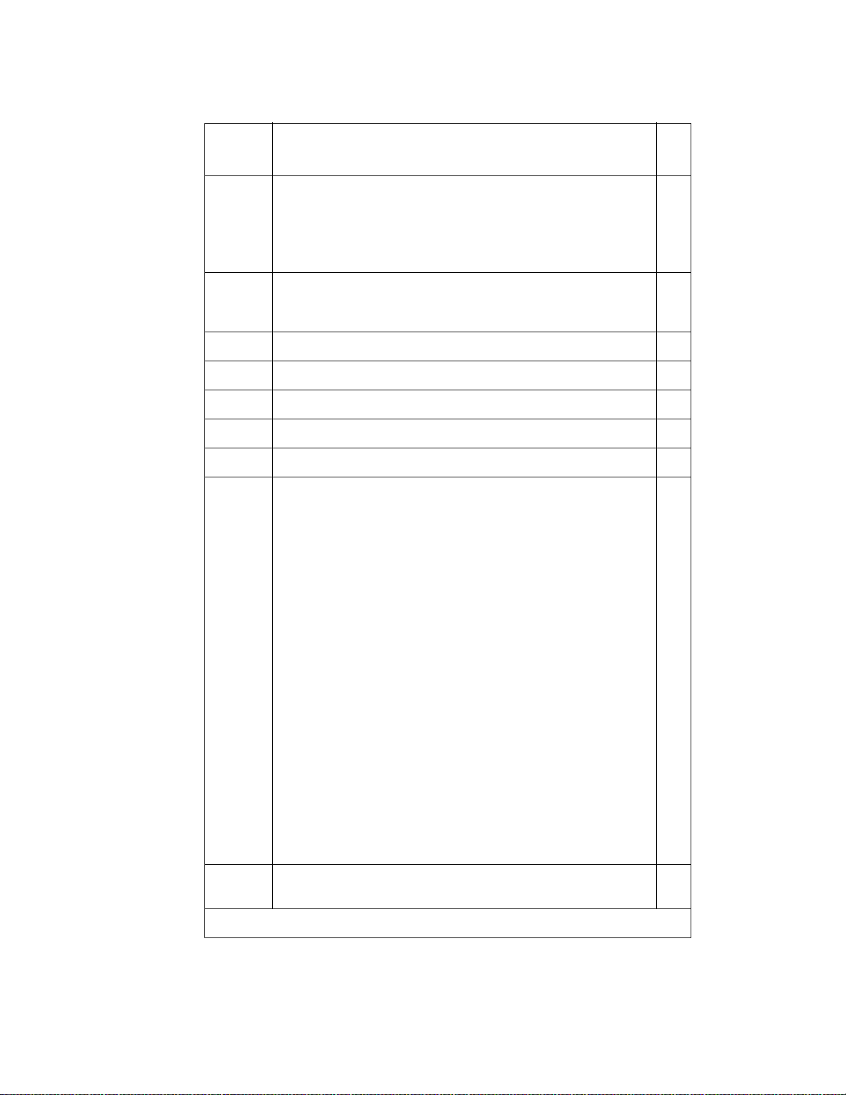
Pre-installation checklist
In order to be properly prepared for the installation, have the items listed in Table 2 ready.
Table 2: Pre-installation checklist
Item
No.
1. Software Release Letter
2. Avaya Communication Manager on removable media
3. Extra formatted removable media
4. Authorized wrist grounding strap
Item
✔
1 of 3
Issue 10 June 2005 25
Page 26
Installing and Cabling the Cabinets
Note:
Table 2: Pre-installation checklist (continued)
Item
Item
No.
5. Documentation (book or PDF file):
● Maintenance for Avaya DEFINITY Server CSI
● Administrator’s Guide for A vaya Communication
Manager
6. Your personal Singl e Sign-On (SSO) for RFA website
authentication login (for Avaya personnel , use your NT
Global Domain login).
7. SAP order number(s) with RTUs
8. Processor faceplate serial number(s)
9. Transaction Record number
10. System Identification (SID) number
11. Switch telephone number or IP address
12.
Access to the RFA In formation page for these items
(if not already installed on your PC):
- Features Extraction Tool (FET) application
(used only for G3V4 through Release 9csi
releases upgrading to Avaya Communication
Manager). Integrated FET is also available
within the RFA application.
✔
- License Installati on Tool (LIT) application (used
to install an RFA license on any Release 10 or
later DEFINITY Server CSI).
Note: For Release 10 and later, the FET tool
is not used because the RFA license
contains the existing switch
configuration information. For
Releases G3v4 and earlier, the FET is
not used. Instead, existing switch
configuration information is captured
using the ASD tool and process.
13. Adobe Acrobat Reader application installed on your
PC (to read FET and LIT documentation)
26 Installation, Upgrades and Additions for Avaya CMC1 Media Gateways
2 of 3
Page 27
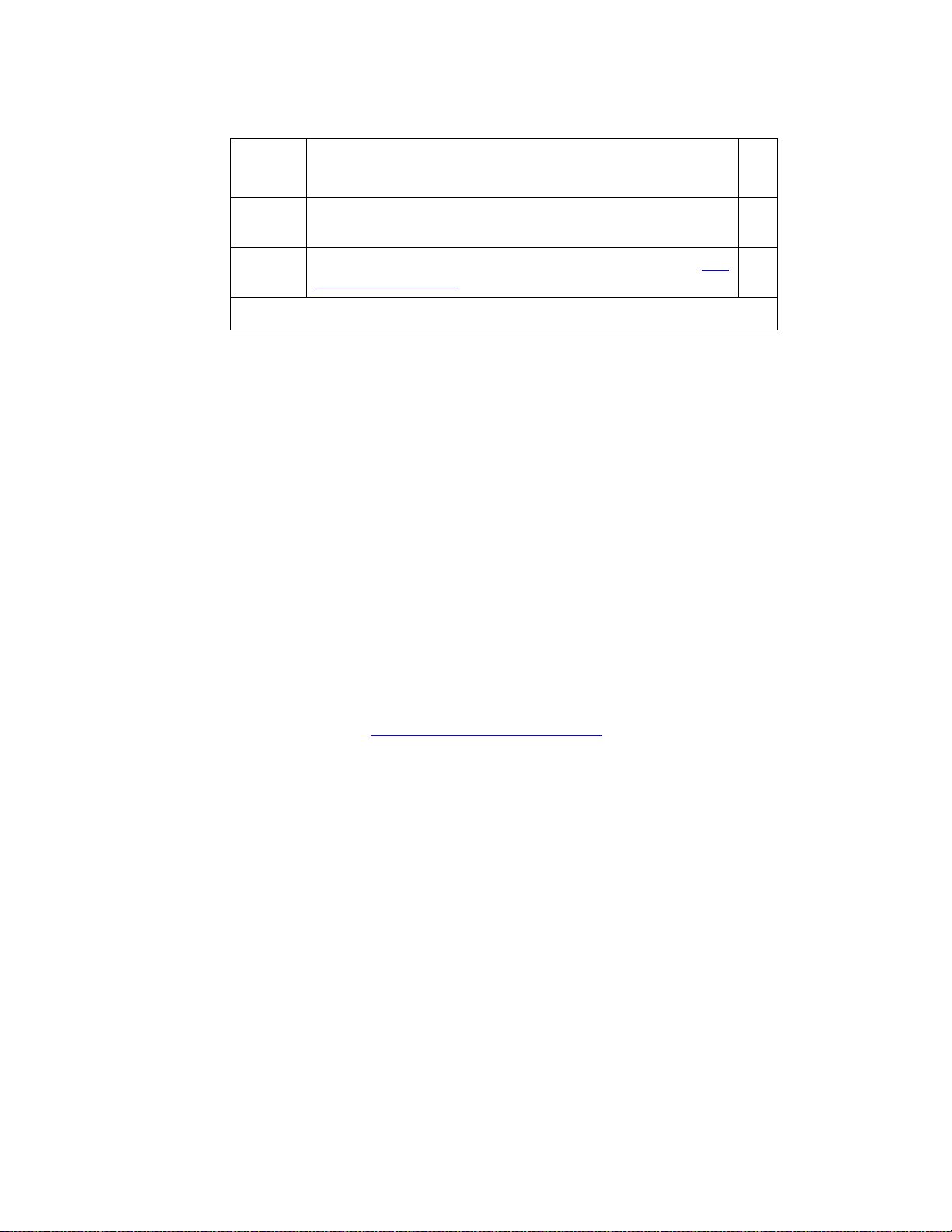
Note:
Table 2: Pre-installation checklist (continued)
Read This First
Item
No.
14. Internet Explorer 5.0 or higher installed on your laptop/
15. Intranet access to your designated RFA portal (see Go
Go to the RFA website
The Remote Feature Activation (RFA) website automates some of the upgrade procedures,
including generating a License File.
1. At your laptop/PC browser, go to the http://rfa.avaya.com Website:
2. Using your SSO, log in to the RFA website.
3. Follow the links to the RFA Information page.
4. Complete the information necessary to create a License File.
Note: You must enter a valid hardware serial number before you can actually create a
license file. If you don’t have a valid hardwar e serial number, you can exit RFA
while you get the number. The record you created remains in the Transaction
state until you create the license file.
Item
PC
to the RFA website).
✔
3 of 3
If you have problems with a hardware serial number that is not in the SAP
database, go to the If you have problems with RFA
No direct connection
If you do not have a direct connection between RFA and the switch:
1. Run the Features Extraction Tool (FET) from your laptop/PC to create a Switch
Configuration File.
2. When prompted, type in the Transaction ID number.
3. Use the FET instructions to create a new switch connection profile.
4. Create the Switch Configuration File.
5. Upload the Switch Configuration File to the RF A website.
6. Deliver the License File to your laptop/PC for installation later in this procedure.
section.
Issue 10 June 2005 27
Page 28

Installing and Cabling the Cabinets
If you have problems with RF A
If you get an error message that a hardware seria l number is not in the SAP data base, you must
call the RFA Help desk (Table 3
Table 3: RFA Help desk contact numbers
) to have them correct the SAP information.
Where Who Phone number/
URL
Channel:
● U.S. and Canada
● Variable Workforce
Group
● Avaya contractors
Avaya
Associates
Members
Contractors
U.S. and Canada Business
Partners
866-282-9248
or
303-354-8999
866-282-9248
or
303-354-8999
EMEA Direct and
Business
Partners
+31-70-414-8720
or
http://
www.avayanetwork
.com
APAC RTAC Direct and
+65-6872-8686
Business
Partners
CALA
● Mexico TAC
● Braz il TAC
● Columbia TAC
Direct and
Business
Partners
+525-278-7878
+5511-5185-6655
+571-616-6077
+5411-4114-4440
+1-720-444-9998
● Argentina TAC
Prompt or
selection
Prompts 2,
4, 2
Prompts 1,
3, 2
Prompt 3
Select GSO;
select EMEA
● Mexico Call Receipt
28 Installation, Upgrades and Additions for Avaya CMC1 Media Gateways
Page 29

Check Customer’s Order
!
Check the customer’s order and the shipping packing lists to confirm that all equipment is
present. If any equipment is missing, report this to your Avaya Inc. represent ative. Check the
system adjuncts for damage and report all damage according to local shipping instructions.
Correcting Shipping Errors
To correct shipping errors:
1. Red-tag all defective equipment and over-shipped equipment and return according to the
nearest Material Stocking Location (MSL) instr uctions. For international customers, contact
your order service agent.
2. Direct all short-shipped reports to the nearest MSL. Contact the appropriate location for
specific instructions. For Streamlined Implementation in the United S tates, call
1-800-772-5409.
Check Customer’s Order
Unpack and Inspect
CAUTION:
CAUTION: A fully loaded system weighs 58 lbs (26.3 kg). Use lifting precautions. If the
doors, power unit, and circuit packs are removed, the unit weighs only 29 lbs
(13.1 kg).
To unpack and inspect equipment:
1. Verify the equipment recei ved. See Figure 1: Equipment Packed with the Compact Modular
Cabinet on page 30. Actual equipment may vary in appearance and may ship in separate
packages.
Equipment comcodes are listed in Table 4: Comcodes for CMC1
2. Before mounting the cabinets, remove the cabinet doors by opening them and lifting them
straight up and off of the hinge pins.
on page 31.
Issue 10 June 2005 29
Page 30
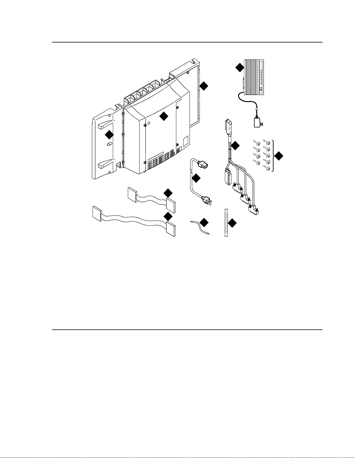
Installing and Cabling the Cabinets
Figure 1: Equipment Packed with th e Compact Modular Cabinet
1
4
3
2
6
5
7
8
9
qrdmpart KLC 011598
Figure notes:
1. Left panel (also acts as a wall-mount
template and as a floor mount pedestal)
2. Compact modular cabinet
3. Right panel
4. U.S. Robotics external modem (not shipped
with all systems)
5. #12 x 1-inch shoulder screws
6. Processor interface cable (not shipped with
all cabinets)
10
11
7. AC power cord (NEMA 5-15P or IEC
320)
8. Vertical TDM/LAN bus cable (not
shipped with all systems)
9. Horizontal TDM/LAN bus cable (not
shipped with all systems)
10. 14-in. (35.5 cm) 6 AWG (#40)
(16 mm
2
) ground wire
11. Single-point ground block
30 Installation, Upgrades and Additions for Avaya CMC1 Media Gateways
Page 31

Comcodes for CMC1
Table 4 lists the comcodes for equipment used with the CMC1.
Table 4: Comcodes for CMC1
Comcode Description
700225758 Left Panel
847951670 Right Panel
700225360 Right Door
700225766 Left Door
847960002 Processor Interface Cable
108516683 TN2402 Processor Circuit Pack
Comcodes for CMC1
107784019 TN2182C Tone-Clock
407633999 U.S. Robotics S portster Model USR 33.6 EXT External Modem
105631527 TDM/LAN Bus Terminator (AHF110)
407772870 Vertical TDM/LAN Bus Cable (WP-91716 List 8)
407772888 Horizontal TDM/LAN Bus Cable (WP-91716 List 9)
706827717 Single-Point Ground Block
H600-487 14-inch (35.5 cm) 6 AWG (#40) (16 mm
847987187 CMC 110 Cross-Connect Assembly (Main Distribution Frame)
407676691 120 VAC Power Distribution Unit (145D 6-AC)
107949364 650A Power Supply
700225782 Fan Assembly
407745009 Fan Air Filter
405362641 120 VAC Power Cord (U.S.)
407786623 120 VAC Power Cord (Europe)
— Tone Detector and Call Classifier Circuit Pack
2
) Green Ground Wire
407786599 120 VAC Power Cord (United Kingdom)
407786631 120 VAC Power Cord (Australia)
1 of 3
Issue 10 June 2005 31
Page 32

Installing and Cabling the Cabinets
Table 4: Comcodes for CMC1 (continued)
Comcode Description
407790591 120 VAC Power Cord (India)
106278062 Apparatus Blank (Circuit Pack Blank) (158P)
108724907 8-Mbyte Mass-Storage Translation Card (White Card)
108724915 16-Mbyte Mass-Storage Translation Card (White Card)
108724923 48-Mbyte Mass-Storage Translation Card (White Card)
106606536 Integrated Channel Service Unit (ICSU) (120A2)
107988867 DS1 Loopback Jack (T1 Only) (700A)
107152969 75-ohm DS1 Coaxial Adapter (888B)
403613003 157B Connecting Block
406948976 6SCP-110 Protector
107435091 507B Sneak Current Fuse Panel
407216316 220029 Sneak Current Fuse
403613003 157B Connecting Block
103970000 Main Distribution Frame Label (Code 220A)
104307327 C6C cable — 50-ft (15.2 m) shielded DS1 cable with 50-pin male to
15-pin male
104307376 C6D cable — 50-ft (15.2 m) shielded DS1 cable with 50-pin male on
each end
104307434 C6E cable — 100-ft (30.5 m) shielded DS1 cable with 50-pin male to
50-pin female
104307475 C6F cable — 50-ft (15.2 m) shielded DS1 cable with 50-pin male to
3 in. (7.6 cm) stub
102381779 3B1A Carbon Block
104410147 3B1E-W Wide Gap Gas Tube
105514756 3C1S Solid State
102904893 4B1C Carbon Block with Heat Coil
104401856 4B1E-W Wide Gap Gas Tube with Heat Coil
104386545 4C1S Solid State with Heat Coil
32 Installation, Upgrades and Additions for Avaya CMC1 Media Gateways
2 of 3
Page 33

Table 4: Comcodes for CMC1 (continued)
Comcode Description
406948976 SCP-110 Sneak Current Protector
407216316 220029 Fuse Sneak Current Protector
105581086 4C3S-75 Solid State with Heat Coil
406144907 ITW LINX Gas Tube, Avalanche Suppress
901007120 ITW Linx Ground Bar (used with above)
406304816 ITW Linx Replacement Fuse
103972758 Data Link Protector (1 circuit)
103972733 Data Link Protector (8 circuits)
407063478 Electrostatic Discharge (ESD) Wrist Strap
107731853 Single-Mode Fiber Optic Tr ansceiver (300A)
Comcodes for CMC1
106455348 Multi-Mode Fiber Optic Transceiver (9823A)
106455363 Multi-Mode Fiber Optic Transceiver (9823B)
407439975 Multi-mode Fiber Interconnect Cable —
407598325 Single-mode Fiber Interconnect Cable —
105357727 Single-mode Fiber Optic Patch Cord —
20 ft (6.1 m)
20 ft (6.1 m)
2 ft (0.6 m)
106060718 Single-mode 5-dB Attenuator
106060734 Single-mode 10-dB Attenuator
3 of 3
Issue 10 June 2005 33
Page 34

Installing and Cabling the Cabinets
Install the System Cabinets
Set the Carrier Address ID — All Cabinets
Figure 2: Setting Carri er Address ID (Right Side)
Figure notes:
swdmdip KLC 082002
A
123456
OFF
B
123456
C
123456
OPEN
OPEN
OPEN
1. Carrier A switch settings
3. Carrier C switch settings
2. Carrier B switch settings
1. Proceed to either Floor-Mount the Cabinet on page 35 or to Wall-Mount the Cabinets on
page 36.
34 Installation, Upgrades and Additions for Avaya CMC1 Media Gateways
Page 35

Floor-Mount the Cabinet
The cabinet dimensions (with floor pedest al) are 28.5 in. (72.4 cm) hi gh, 24.5 in. (62. 2 cm) wide,
and 12 in. (30.5 cm) deep. Mai ntain a servic e clearance of 12 in. ( 30.5 cm) on the l ef t, righ t, and
front of the cabinet.
Figure 3: Typical Floor Mount Installation
Install the System Cabinets
3
Figure notes:
1. Left panel (floor-mount pedestal)
2. #12 x 1-in. (2.5 cm) shoulder screws
1. Proceed to Cable the System on page 50.
1
2
indmflor KLC 110397
3. 12 in. (30.5 cm) minimum from nearest
object (required to service the circuit packs)
Issue 10 June 2005 35
Page 36

Installing and Cabling the Cabinets
!
Note:
Wall-Mount the Cabinets
CAUTION:
CAUTION: A fully loaded system weigh s 58 lb (26. 3 kg ). Use l ifting precautions. If the doors,
power unit, and circuit packs are removed, the unit weighs only 29 lb (13.1 kg).
Install Plywood Backing onto Wall
The plywood and the hardware to mount the plywood are installer- provided.
Note: The following plywood dimensions account for the extra space needed to install
the panels on each side of the cabinet. The cabinet is 24 in. (0.6 m) wide and
each panel is 12 in. (0.3 m) wide.
Single-Cabinet Installation
1. Install a 3/4-in. (2 cm) thi ck sheet of 2 x 4- f t (0. 6 x 1.2 m) p lywoo d horiz ontally onto the wall.
See Figure 4: Left Panel Used as Mounting Template
on page 37.
The top of the plywood must be at least 54 in. (137 cm) from the floor.
2 or 3 Vertically Mounted Cabinets
1. Install a 3/4-in. (2 cm) thick sheet of 4 x 8-ft (1.2 x 2.4 m) plywood vertically onto the wall.
See Figure 6: Typical Vertical Multicabinet Inst allation
on page 39.
2 Cabinets Vertically Mounted and 1 Cabinet Horizontally Mounted
1. Install a 3/4-in. (2 cm) thick sheet of 4 x 8-ft (1.2 x 2.4 m) plywood vertically onto the wall.
See Figure 6: Typical Vertical Multicabinet Inst allation
2. Install a 3/4-in. (2 cm) thick sheet of 2 x 4- f t (0.6 x 1. 2 m) sheet of pl ywood hori zont al ly onto
the wall. Position the plywood to the right of the fir st sheet, across from Cabinet A.
on page 39.
36 Installation, Upgrades and Additions for Avaya CMC1 Media Gateways
Page 37

Install Cabinet A — Wall-Mount
Figure 4: Left Panel Used as Mounting Template
Install the System Cabinets
To wall-mount cabinet A:
1. Place the template on the wall ensuring that the top surface is le vel.
2. Mark two 1/8-in. (0.3 cm) pilot holes in the mounting hole locations.
3. Remove the template from the wall.
4. Drill the two pilot holes.
5. Thread two #12 x 1-in. shoulder screws partially into the holes.
6. Set the cabinet onto the wall and align the slots with the shoulder screws. See
Figure 5: Typi cal Wa ll-Mount Install ation
place. Tighten the screws securely.
on page 38. Slide the cabinet to the left to hold it in
Issue 10 June 2005 37
Page 38

Installing and Cabling the Cabinets
!
Figure 5: Typical Wall-Mount Installation
1
A
2
FLOOR
indmins1 KLC 110397
Figure notes:
1. #12 x 1-in. shoulder screws 2. #12 x 1-inch safety screw
7. Drill two lower mounting holes using the cabinet as a template.
8. Thread the 2 lower screws and tighten.
CAUTION:
CAUTION: Be sure the right bottom safety screw is in place and tight.
38 Installation, Upgrades and Additions for Avaya CMC1 Media Gateways
Page 39

Install 2 or 3 Vertically Mounted Cabinets
Figure 6: Typical Vertical Multicabinet Installation
Install the System Cabinets
12"
(30.5 cm)
1
1
78 1/2"
(199.4 cm)
29 1/2"
48" (122 cm)
1
A
2
B
C
(75 cm)
Floor
indmins7 KLC 082002
Figure notes:
1. #12 x 1-inch shoulder screws 2. #12 x 1-inch safety screw
To install vertically-mounted cabinets:
1. Securely tighten the shoulder screws and safety screws.
5" (12.7 cm)
Issue 10 June 2005 39
Page 40

Installing and Cabling the Cabinets
Install 2 Cabinets Vertically and 1 Cabinet Horizontally
Figure 7: Typical 3-Cabinet Installation
1
1
29 1/2"
(75 cm)
Figure notes:
12"
(30.5 cm)
1
B
2
54"
(137 cm)
96" (244 cm)
A
3
C
5" (12.7 cm)
Floor
indmins9 KLC 082002
1. #12 x 1-inch shoulder screws
2. #12 x 1-inch safety screw
3. Sec ond sh eet of
plywood
To install two cabinets verticall y and one cabinet horizontally:
1. Securely tighten the shoulder screws and safety screws.
40 Installation, Upgrades and Additions for Avaya CMC1 Media Gateways
Page 41

Install Left and Right Panels — Wall-Mount
Figure 8: Left and Right Panel Installation
1 2
Install the System Cabinets
indmins3 KLC 082002
Figure notes:
1. Left panel 2. Right panel
To wall mount the left and right panels:
1. Align the cutouts in the panels with the cabinet hinges .
2. Drill a 1/8-inch (0.3 cm) pilot hole into the wall and secure the panels with the #12 x 1-inch
shoulder screws.
Issue 10 June 2005 41
Page 42

Installing and Cabling the Cabinets
!
!
!
!
AC Power and Ground
CAUTION:
CAUTION: The system requires a dedicated AC power circuit that is not shared with other
equipment and is not controlled by a wall switch. The AC receptacle must not be
located under the Main Distribution Frame and must be easily accessible.
CAUTION:
CAUTION: The latch only removes DC power from the cabinet. Unseating the power suppl y
removes AC power from the power supply, but not from the cabinet. To remove
AC power from the cabinet, pull the AC power cord from the AC appliance
connector on the rear of the cabinet.
CAUTION:
CAUTION: System grounding must comply with the general rules for grounding provided in
Article 250 of the National Electrical Code (NEC), National Fire Protection
Agency (NFPA) 70, or the applicable electric code in the country of installati on.
CAUTION:
CAUTION: AC mains wiring and testing must be performed by a qualified electrician and
must conform to Article 250 of the Nati onal Electrical Code (NEC), National Fire
Protection Agency (NFPA) 70, or the applicable electric code in the country of
installation.
Check AC Power
Each CMC uses an auto-ranging 85 to 264 VAC power supply, 47 to 63 Hz, 330 W, 4.5 amps
(100-120 V AC) or 2.3 amps ( 200 to 240 VAC), at 500 VA. The AC power source can be 1 phase
of 120 VAC with neutral (100 VAC for Japan) with 15 amp circuit breaker, or 1 phase of 220 or
240 VAC (200 VAC for Japan) with 10 amp circuit breaker. The AC cord uses a NEMA 5-15P
plug or an IEC 320 plug.
Before powering up the system, check the AC power in the equipment room using a KS-20599
digital voltmeter (DVM) (or equivalent).
1. Measure the AC voltage between the hot and neutral side of the receptacle.
2. Depending on the AC power source, verify that the meter reads 90 to 132 VAC or 180 to
264 VAC. If not, have a qualified electrician correct the problem.
3. Measure the voltage between the neutral and ground side of the receptacle.
4. Verify that the meter reads 0 VAC. If not, have a qualified electrician correct the problem.
5. When finished, set the AC mains circuit breakers to OFF.
42 Installation, Upgrades and Additions for Avaya CMC1 Media Gateways
Page 43

Approved Grounds
!
An approved ground is the closest acceptable medium for groundi ng the building entrance
protector, entrance cable shield, or single-point ground of electronic telephony equipment. If
more than 1 type of approved ground is available on the premises, the grounds must be bonded
together as required in Section 250-81 of the Nati onal Electrical Code.
Grounded Building Steel — The met al frame of the buildi ng where it is ef fectively gro unded by
1 of the following grounds: acceptable metallic water pipe, concrete encased ground, or a
ground ring.
Acceptable Water Pipe — A metal underground water pipe, at least 1/2-in. (1. 3 cm) in
diameter, in direct contact with the earth for at least 10 ft (3 m). The pipe must be electrically
continuous (or made electrically continuous by bonding around insulated joints, plastic pipe, or
plastic water meters) to the point where the protecto r ground wire connects. A metallic
underground water pipe must be supplemented by the metal frame of the building, a
concrete-encased ground, or a ground ring. If these grounds are not available, the water pipe
ground can be supplemented by 1 of the following types of grounds:
● Other local metal underground systems or structures — Local underground structures
such as tanks and piping systems
AC Power and Ground
● Rod and pipe electrodes — A 5/8-in. (1.6 cm) solid rod or 3/4-in. (2 cm) conduit or pipe
electrode driven to a minimum depth of 8 ft (2.4 m)
● Plate electrodes — Must have a minimum of 2 ft
2
(0.185 m2) of metallic surface exposed
to the exterior soil
Concrete Encased Ground — An electrode encased by at least 2 in. (5.1 cm) of concrete and
located within and near the bottom of a concrete foundation or footing in direct contact with the
earth. The electrode must be at least 20 feet (6.1 m) of 1 or more steel reinforcing bars or rods
2
1/2-in. (1.3 cm) in diameter , or at leas t 20 ft (6.1 m) of bare, solid copper, 4 AWG (26 mm
) wire.
Ground Ring — A buried ground that encircles a buil d ing or structure at a depth of at least 2.5
ft (0.76 m) below the earth’s sur face. The ground ring must be at least 20 ft (6.1 m) of 2 AWG
2
(35 mm
), bare, copper wire.
Approved Floor Grounds
CAUTION:
CAUTION: If the approved ground is inside a dedicated equipment room, then these
connections must be made by a qualified electrician.
Floor grounds are those grounds on each floor of a high-rise building that are suitable for
connection to the ground terminal in the riser closet and to the cabinet single-point ground
terminal. Approved floor grounds may include:
● Buildi ng steel
● The grounding conductor for the secondary si de of the power transformer feeding the floo r
● Metallic water pipes
Issue 10 June 2005 43
Page 44

Installing and Cabling the Cabinets
● Power-feed metallic conduit supplying panel boards on the floor
● A grounding point specifically provided in the building for the purpose
Uninterruptible Power Supply
An optional UPS (Uninterruptible Power Supply) may be used for power holdover. The type of
UPS depends on the holdover requirements. Holdover times vary from less than 10 minutes to
up to 8 hours. The UPS must provide surge protection for all connected cabin ets.
1. Connect the UPS to an electrical outlet capable of handling the power requirements of all
cabinets:
a. For 100 VAC, multiply 4.5 amps times the number of cabinets.
b. For 120 VAC, multiply 3.8 amps times the number of cabinets.
c. For 200 VAC, multiply 2.3 amps times the number of cabinets.
d. For 220-240 VAC, multiply 2.0 amps times the number of cabinets.
2. Be sure that Cabinet A (control carrier) is connected to an “unswitched” or “always on”
electrical outlet on the UPS.
44 Installation, Upgrades and Additions for Avaya CMC1 Media Gateways
Page 45

CMC Power Switch
!
8
CAUTION:
CAUTION: The latch only removes DC power from the cabinet. Unseating the power suppl y
removes AC power from the power supply, but not from the cabinet. To remove
AC power from the cabinet, pull the AC power cord from the AC appliance
connector on the rear of the cabinet. See Figure 9
Figure 9: CMC Power Supply
AC Power and Ground
.
Figure notes:
1. Latch
1
psdmdc RPY 01199
Issue 10 June 2005 45
Page 46

Installing and Cabling the Cabinets
Connect Cabinet Grounds and Other Grounds
The following additional grounding requirements must be met:
● The approved ground wire must be green, 6 AWG (#40) (16 mm
(this is in addition to the ground wire in the AC power cord)
● Bond all approved grounds at the single-point g round to for m a si ngle gr ounding el ectr ode
system
Install the Ground Block
To install the ground block
2
), copper , stranded wire
1. Mount the ground block as shown in Figure 10
.
2. Make the cable connections as shown in Figure 11
Figure 10: Ground Block Installation to Right Panel
2
A
.
2
1
Figure notes:
1. #12 x 1-inch shoulder screws 2. Single-point ground block
46 Installation, Upgrades and Additions for Avaya CMC1 Media Gateways
indmingb RPY 012398
Page 47

Figure 11: Typical Cabinet Grounding
AC Power and Ground
6
1
1
3
1
4
5
cadmgrd1 KLC 020698
Figure notes:
1. 6 AWG (#40) (16 mm
ground wire
2. 6 AWG (#40) (16 mm
wire to next cabinet
3. Single-point ground block
2
) cabinet
2
) ground
2
4. AC load center single-point ground
5. 10 AWG (#25) (6 mm
2
) wire to coupled
bonding conductor (CBC)
6. 6 AWG (#40) (16 mm
2
) ground wire from
single-point ground block to the AC load
center single-point ground
Issue 10 June 2005 47
Page 48

Installing and Cabling the Cabinets
!
Install Coupled Bonding Conductor
The Coupled Bonding Conductor (CBC) provides for mutual inductance coupling between the
CBC and the telephone cables that are exposed to lightning. The conductor can be a 10 AWG
(#25) (6 mm
cables, or 6 spare pai rs from the exposed cable.
In a high rise building, connect the CBC to an approved building ground on each fl oor. To
provide the coupled bonding protection:
1. Connect 1 end of the conductor to a telephone cable building entrance protector ground that
is connected to an approved ground.
2. Route the rest of the conductor next to the exposed telephone cables being protected until
they reach the cross-connect nearest to the telephone system.
3. Position the non-exposed telephone cables at least 12 inches (30.5 c m) away from exposed
telephone cables whenever possible.
4. Terminate the other end to the single-point ground block provided for the telephone system.
2
) wire tie wrapped to the e xposed cables, a met al cable s hield around the expos ed
Connect and Route Cabinet AC Power Cords
CAUTION:
CAUTION: The AC power cords may connect to a properly rated power distribution unit,
individual AC power recept acles, or t o a UPS. See Figu re 12: Routing AC Power
Cords to a Power Distribution Unit on page 49.
To connect and route cabinet AC power cords:
1. Be sure the circuit breakers at the AC load center are OFF.
2. Connect Cabinet A to an “unswitched” or “always on” electrical outlet.
48 Installation, Upgrades and Additions for Avaya CMC1 Media Gateways
Page 49

Figure 12: Routing AC Power Cords to a Power Distribution Unit
1
AC Power and Ground
ALWAYSON
POWER
PROTECTION
GROUNDOK
1
LINEFA ULT
2
pcdm5cmc RPY 011998
Figure notes:
1. Cabinet AC power cord 2. Surge-protected AC power distribution unit (120
VAC systems) (optional)
Issue 10 June 2005 49
Page 50

Installing and Cabling the Cabinets
Cable the System
If there is more than one cabinet, you need to interconnect all the cabinets in the system.
Install Processor Interface Cable — Cabinet A
Only and TDM/LAN Bus Terminator
Figure 13: System Cable Connections
cadm1mdsLJK 060297
Figure notes:
1. TDM/LAN bus terminator 2. Processor interface cable (cabinet A only)
To install the processor interface cable:
1. Connect the Processor Interface Cable to slot 1 of Cabinet A. See Figure 13
2. Install the TDM/LAN bus terminators.
50 Installation, Upgrades and Additions for Avaya CMC1 Media Gateways
.
Page 51

Cable the Multi-Cabinet System — Wall-Mount
Vertically Mounted System
To cable a vertically-mounted multi-cabinet system:
1. Route the TDM/LAN bus cables through the cable trough.
See Figure 14
Figure 14: TDM/LAN Bus Cables and Terminators
.
Cable the System
A
B
C
cadm3trm KLC 082102
1
2
2
2
2
1
TOP
1
Figure notes:
1. TDM/LAN bus terminator (at each end
of the TDM/LAN bus)
2. Vertical TDM/LAN bus cable (List 8)
Issue 10 June 2005 51
Page 52

Installing and Cabling the Cabinets
Vertically and Horizontally Mounted System
Only 1 horizontal TDM/LAN Bus cable is allowed per system. See Figure 15.
1. Route the TDM/LAN bus cables through the cable trough.
Figure 15: System Cable Connections
3
Figure notes:
B
C
indmin10 KLC 082002
A
2
1
TOP
1
1
1. TDM/LAN bus terminator (at each
end of the TDM/LAN bus)
3. Horizontal TDM/LAN bus
cable (List 9)
2. Vertical TDM/LAN bus cable (List 8)
52 Installation, Upgrades and Additions for Avaya CMC1 Media Gateways
Page 53

Install Main Distribution Frame (MDF) and External Modem
!
Note:
Install Main Distribution Frame
(MDF) and External Modem
Install the MDF
CAUTION:
CAUTION: The optional MDF is a special 110 cross-connect field and is smaller than
standard 110 cross-connect hardware. Do not install standard 110 hardware
inside the right panel.
Note: The depth of any equipment installed inside the right panel must not exceed 2.5
inches (6.3 cm), otherwise the right cover panel cannot fit over the right panel.
The optional MDF represents the trunk/auxiliary field.
1. Mount the optional MDF to the right panel using one of the following:
● For bottom-mount MDFs, refer to Bottom-mounted MDF with Modem on page 53.
● For top-mount MDFs (in cabinets other than cabinet A),
refer to Top-Mounted MDF
● For dual-mount MDFs, refer to Dua l MDFs on page 56.
on page 55.
Bottom-mounted MDF with Modem
To install a bottom-mounted MDF with a modem:
1. On the rear of the MDF, cut the cable tie securing the top 5 cables to the MDF mounting
frame.
2. Mount the MDF to the right panel. See Figure 16: Typical Bottom-Mount MDF and Modem
Cable Routing on page 54.
3. Secure all 10 cables to the bottom left bracket on the MDF with a cable tie.
Issue 10 June 2005 53
Page 54

Installing and Cabling the Cabinets
Figure 16: Typical Bottom-Mount MDF and Modem Cable Routing
10109988776
554433221
2
6
1
1
2
3
4
5
6
7
8
9
10
1
4
1
3
Figure notes:
1. Main distribution frame (MDF)
2. External modem
cadmrpnl KLC 070698
3. Processor interface cable (connect P2 to
modem, connect J1 to cable 1 on MDF)
4. #12 x 1-inch shoulder screw
54 Installation, Upgrades and Additions for Avaya CMC1 Media Gateways
Page 55

Top-Moun ted MDF
Use this configuration when the cabinet is wall-mounted, and is near the floor. Do not use this
configuration for cabinet A.
Figure 17: Typical Top- Mount MDF Cable Routing
10109988776
Install Main Distribution Frame (MDF) and External Modem
1
2
3
4
5
6
6
7
8
9
10
1
1
554433221
3
2
cadmmdf2 KLC 070698
Figure notes:
1. Main distribution frame (MDF)
3. #12 x 1-inch shoulder screw
2. Connect cable 1 to slot 1
To install a top-mounted MDF:
1. On the rear of the MDF, cut the cable tie securing the top 5 cables to the MDF mounting
frame.
2. Mount the MDF to the right panel. See Figure 17
.
3. Secure all 10 cables to the bottom left bracket on the MDF with a cable tie.
Issue 10 June 2005 55
Page 56

Installing and Cabling the Cabinets
Dual MDFs
Use this configuration when mounting two MDFs.
Figure 18: Preliminary Dual-Mount MDF Cable Routing
10109988776
6
554433221
2
Figure notes:
1. Main distribution frame (MDF)
2. Connect cable 1 to slot 1
1
1
2
3
4
5
6
7
8
9
10
1
1
3
cadmrpn2 KLC 070698
3. To external modem
56 Installation, Upgrades and Additions for Avaya CMC1 Media Gateways
Page 57

Install Main Distribution Frame (MDF) and External Modem
To install two MDFs:
1. On the rear of the MDF, cut the cable tie securing the top 5 cables to the MDF mounting
frame.
2. Mount the MDF to the bottom position on the right panel. See Figure 18: Preliminary
Dual-Mount MDF Cable Routing on page 56.
3. Secure all 10 cables to the bottom left bracket on the MDF with a cable tie.
4. Mount the second MDF to the top position on the right panel. See Figure 19
Figure 19: Typical Dual-Mount MDF Cable Routing
1
2
3
4
10109988776
554433221
5
6
1
6
7
8
9
10
1
2
3
4
5
6
7
8
9
10
1
.
2
cadmrpn3 LJK 050198
Figure notes:
1. Main distribution frame (MDF) 2. #12 x 1-inch shoulder screw
Issue 10 June 2005 57
Page 58

Installing and Cabling the Cabinets
Note:
Install the External Modem
The U.S. Robotics S portster Model USR 33.6 EXT external modem is the recommended
external modem. Avaya CMC1 Media Gateways operate with this mode m set to the fac tory
default settings.
Note: You may use a locally obtained, type-approved external modem (33.6 kbps and
V.34 protocol). Contact your Avaya Inc. representative for more information.
To install the external modem:
1. Use installer-provided hardware to mount the modem. See Figure 16: Typical
Bottom-Mount MDF and Modem Cable Routing on page 54. If top-mounting MDFs or
dual-mounting MDFs, mount the external modem to the plyw ood in a locat ion which allows
the standard connection to the interconnect cable.
2. Route the MODEM cable (P2) from the Processor Interface Cable through the cable trough
and to the modem.
3. Connect the cable to the modem. Refer to Processor Interface Cable Pinout
for the pinout of the modem cable.
4. Plug the modem power cord into an electrical outlet and turn on the modem.
5. Modem setup and administration is performed in External Modem Option Settings
page 147.
Install Equipment Room Hardware
Refer to DEFINITY Communications System Generic 1 and Generic 3 Main Distribution Field
Design, 555-230-630, for more information.
Cross-Connect the Cabinets to the MDF
To cross-connect the cabinets to the MDF:
1. Cross-connect the ports on the trunk and line circuit packs to the MDF as required. See
Figure 21: Example MDF Connections
on page 63.
on page 165
on
58 Installation, Upgrades and Additions for Avaya CMC1 Media Gateways
Page 59

Circuit Pack Installation
!
Note:
CAUTION:
CAUTION: When handling circuit packs or any components of a DEFINITY System, always
wear an authorized wris t ground s trap. Connec t the stra p to the ground connecto r
provided on the system cabinet.
Note: Unlike previous releases of DEFINITY, the circuit pack slots in the CMC are not
purple or white. This is because all of the circuit pack slots in the CMC are
“universal slots.” That is, any slot can contain any type of port circuit pack.
Circuit Pack Slot Loading
In general, load the circuit packs so that the numb er of packs in each cabinet i s about equal and
the trunks and lines are evenly distributed among the cabinets. See Figure 20: Control Carrier
Slot Layout on page 60.
Install Equipment Room Hardware
To install circuit packs:
1. Install the TN2402 Processor circuit pack in slot 1 of Cabinet A.
2. Install the TN2182C Tone-Clock circuit pack in slot 2 of Cabinet A.
Load all port circuit packs starting with Cabinet A first, Cabinet B next, and so forth. Return to
Cabinet A and repeat.
3. A TN744E Call Classifier/Tone Detector circuit pack may be r equired i n syst ems wit h heav y
traffic. Install the TN744E into any port slot. Slot 1 of Cabinet B is preferred.
4. See Table 5: Circuit Pack Installation Order (Loading)
on page 61 for the recommended
circuit pack layout for the control carrier and the port carriers.
Issue 10 June 2005 59
Page 60

Installing and Cabling the Cabinets
Figure 20: Control Carrier Slot Layout
1
6
MAJ
MIN
ON
XFR
AUTO
EM
OFF
ER XFER ON
AMBER CARD IN USE
RED EM
T
T
N
N
2
2
1
4
8
0
2
2
B
123 4
2
10
5
scdmlft3 KLC 090700
Figure notes:
1. Line circuit pack slots 2. Trunk circuit pack slots
60 Installation, Upgrades and Additions for Avaya CMC1 Media Gateways
Page 61

Install Equipment Room Hardware
Table 5: Circuit Pack Installation Order (Loading)
Function Apparatus Code Load From Notes
Processor TN2402 Slot 1 in
Cabinet A
Tone Clock TN2182C Slot 2 in
Cabinet A
Call Classifier/ Tone
Detector
TN744E Slot 1 of
Cabinet B
If slot is not available, load
in first available slot from
slot 1.
DEFINITY AUDIX ED-1E546 (TN566/
TN567)
Slots 6-9 TN566 and TN567 require
4 slots with overlap into
area to the left of slot 6. In
any other position, 5 slots
are required.
DEFINITY AUDIX
Slim
TN568 Slot 6 TN568 requires 2 slot s.
If there is a fiber-optic
interface and slot 6 is
occupied, use slots 7 and
8.
Announcement TN750C Lower Left
Speech Synthesizer TN725B Lower Left
DS1/E1, ISDN PRI TN464HP, TN767E,
TN2242, TN464CP
(Guestworks and
BCS only)
Lower Left Maximum of 8 ISDN-PRI.
Total number of ISDN-PRI
plus number of ISDN-BRI
circuit packs must not
exceed 8.
ISDN-BRI Trunk TN2185B Lower Left Maximum of 4
CO Trunk TN747B, TN465C,
Lower Left
TN2199, TN2147C,
TN2138, TN438B
DID Trunk TN753B, TN2139,
Lower Left
TN2146, TN436B,
TN459B
Tie Trunk TN760E, TN497,
Lower Left
TN2140B
Auxiliary Trunk TN763D Lower Left
Modem Pool TN758 Lower Left
1 of 2
Issue 10 June 2005 61
Page 62

Installing and Cabling the Cabinets
Table 5: Circuit Pack Installation Order (Loading) (continued)
Function Apparatus Code Load From Notes
Data Line TN726B Upper Left
Digital Line TN754C, TN2181,
Upper Left
TN2224CP,
TN2214CP
Analog Line TN746B, TN2183,
Upper Left
TN2215,
TN468B,TN791,
TN2214CP
Hybrid Line TN762B Upper Left
Radio Controller TN789B Upper Left
ISDN-BRI 4-Wire S/
TN556D Upper Left
T-NT Line (A-Law)
5. Cross-connect the port circuit packs to the MDF. See Figure 21.
2 of 2
62 Installation, Upgrades and Additions for Avaya CMC1 Media Gateways
Page 63

Figure 21: Example MDF Connections
110194132221120
4
Port Tie Trunk
4 Port Tie Trunk
w/ E&M Signaling
Port Analog
8
8
Port CO
Port Data Line8
Port DID8
Issue 10 June 2005 63
Port Digital8
Port Hybrid8
Port BRI12
Port Analog
16
Port Digital
16
Port Analog
24
Port Digital
24
514233122161524918
71625817
Install Equipment Room Hardware
Channel DS1
24/32
widfccf3 KLC 020802
5
1
615
4
7
918
10 19
13
12 21
14
16 258
17
20
233
24
22211
Page 64

Installing and Cabling the Cabinets
Off-Premises Circuit Protection
Protection from hazardous volt ages and current s is re quired for al l of f-pre mises (out of bui ldin g)
trunks, lines, and ter minal inst allati ons. Both ov er-volt age pr otection ( lightni ng, power induction,
and so forth), and sneak current protection are required. Sneak current protectors must be
either UL listed/CSA certified, or must comply with local safety standards.
Sneak current protectors must have a maximum rating of 350 mA, and a minimum voltage
rating of 600V, or as required by local regulations. The following devices protect the system
from over-voltages:
● Analog trunks use the 507B sneak protector or equivalent. Over-volt age protection is
normally provided by the local telephone company.
● Analog voice terminals use one of the foll owing types of combined over-vo ltage and sneak
current protection, or equival ent:
- Carbon block with heat coil for UL code 4B1C
- Gas tube with heat coil for UL code 4B1E-W
- Solid state with heat coil for UL code 4C1S
● DCP and ISDN-BRI terminals use the solid state 4C3S-75 with heat coil protector, or
equivalent
● DS1/E1/T1 circuits require isolation from exposed facilities. This isolation may be provided
by a CSU (T1), LIU (E1), or other equipment that provides equivalent protection
Install Sneak Fuse Panels
Sneak current protection is required between the incoming RJ21X or RJ2GX network interface
and the system for both trunk and off-premises circuit packs. The model 507B sneak current
fuse panel, or equivalent, is recommended for sneak current protection. See Figure 22
.
64 Installation, Upgrades and Additions for Avaya CMC1 Media Gateways
Page 65

Figure 22: Model 507B Sneak Fuse Panel
Note:
sneakCJL032096
Sneak
Current
Protector
507B
Install Equipment Room Hardware
Figure notes:
1. Sneak current protector (PEC 63210)
2. 25-pair male connector (In)
3. 25-pair female connector (Out)
4. 220029 fuses (inside panel). Use a small
screwdriver to pry top cover off
Approximately 8 inches (20 cm) of horizont al wall space is required for each column of sneak
fuse panels. Connector cabl es co nnect the net work interf ace to the s neak f use panel . Also , use
157B connecting blocks equipped with SCP-110 protectors for sneak current protection.
Note: Sneak current protectors with a rating of 350 mA at 600 V must be UL listed for
United States installations and CSA certified for Canadian installations. The
panel contains two 25- pair con nectors, fus e removal too l, and fif ty 220029 Sneak
Fuses (and 2 spares). Use the SCP-110 protectors with 110-type hardware and
on the 507B Sneak Fuse Panel. The SCP-110 Protectors can be ordered
separately and installed on the 157B connecting block. Fifty protectors are
required per block.
To install sneak fuse panels:
1. Install the 507B near the network interface or MDF with locally-obtained #12 x 3/4-inch
screws (or equivalent).
Issue 10 June 2005 65
Page 66

Installing and Cabling the Cabinets
Table 6 is a pinout of the cable wiring and associated fuse numbers.
Table 6: Sneak Fuse Connector Pinout
Connector
Pin Numbers
Pair/Fuse
Number
26/1 1
27/2 2
28/3 3
29/4 4
30/5 5
31/6 6
32/7 7
33/8 8
34/9 9
35/10 10
36/11 11
37/12 12
38/13 13
39/14 14
40/15 15
41/16 16
42/17 17
43/18 18
44/19 19
45/20 20
46/21 21
47/22 22
48/23 23
1 of 2
66 Installation, Upgrades and Additions for Avaya CMC1 Media Gateways
Page 67

Install Equipment Room Hardware
Table 6: Sneak Fuse Connector Pinout (continued)
Connector
Pin Numbers
49/34 24
50/25 25
Label the Main Distribution Frame
Figure 23 shows the graphic symbols used on the supplied labels for the system,
cross-connections, information outlets, and cables.
To label the MDF:
1. Write the floor and building identification on each label as required.
2. Insert the labels into the plastic holders.
3. Snap the holders into the appropriate locations on the MDF.
Figure 23: Label Graphic Symbols and Nomenclature
Pair/Fuse
Number
2 of 2
r758422i LJK 050996
Figure notes:
1. Floor and building identification
2. Cabinet
3. Carrier
4. Slot
5. Information outlet
6. Site/satellite closet
7. Tie circuit
8. Floor
9. Building
4. Label the cables as required using the supplied l abels. Label code number 220A (Comcode
103970000) contains all required labels.
Issue 10 June 2005 67
Page 68

Installing and Cabling the Cabinets
Note:
Set Up System Access
For SAT commands, use a terminal emulation application, such as Avaya Native Configuration
Manager or HyperTerminal. You can also use Avaya Site Administration, part of Avaya
Integrated Management.
Starting Terminal Emulation
Note: Avaya™ Native Configuration Manager and HyperTerminal are supported
terminal emulation applications.
To start a terminal emulation session:
1. On the services laptop open a VT- 100 terminal emulation sess ion using an appl ication s uch
as Avaya Terminal Emulation.
2. Administer the terminal emulation port settings:
● 9600 baud
● No parity
● 8 data bits
● 1 stop bit
● No flow control
3. Log into the media server as craft or dadmin.
Connecting a PC
You can connect your PC/laptop either directly (5 0 ft [15 m] or less) or remotely through a dat a
module or a modem.
68 Installation, Upgrades and Additions for Avaya CMC1 Media Gateways
Page 69
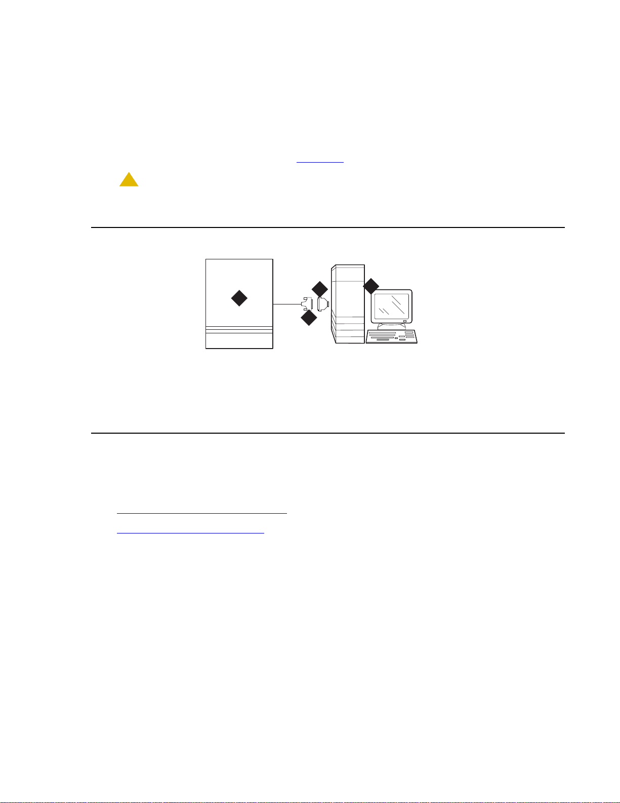
Direct con n e c t io n
!
You can connect directly from the PC if it is 50 ft (15 m) or less from the Avaya CMC1 Media
Gateway.
To connect a PC directly:
Set Up System Access
1. Connect the equipment as shown in Figure 24
.
CAUTION:
CAUTION: For a DC-powered system, install an EIA 116A Isolator (comcode 106005242) in
series between the cable and the TERM, DOT, or Terminal Active connector.
Figure 24: A typical direct connection
4
Management
1
cydfdr23 KLC 090700
Figure notes:
1. Avaya CMC1 Media Gateway (PPN)
2. 50-ft (15-m) M25A cable (RS-232)
3
2
3. 9-to-25 pin adapter if needed
4. Computer with Avaya Integrated
Remote connection
You can remotely access the Avaya CMC1 Media Gateway by:
● Connecting through a data module
● Connecting by analog modem
Issue 10 June 2005 69
Page 70

Installing and Cabling the Cabinets
Note:
Connecting through a data module
If more than 50 ft (15 m) from the Avaya CMC1 Media Gateway, you can connect the PC
through a data module.
To connect a PC through a data module:
1. Connect the equipment as shown in Figure 25
.
Figure 25: A typical remote connection using an 8400B (top) or 7400B (bottom) data
module
Figure notes:
1
4
2
3
1
4
2
3
5
5
8
10
7
6
9
10
9
8
11
11
cydfdr08 LJK 101701
12
12
1. Avaya CMC1 Media Gateway
2. Digital line circuit pack
3. B25A 25-pair cable
4. Main distribution frame (MDF)
5. 103A or modular wall jack
6. 400B2 adapter
7. D6AP power cord (8400B+ only)
Note: With a 7400B+ data module, use a 4-wire digital line circuit pack. With the
8. Data module power supply
9. 7-ft (2-m) D8W modular cord
10. Data module (8400B+ [top] or 7400B+
[bottom])
11. 50-ft (15-m) M25A cable (RS-232)
12. Computer with Avaya Site
Administration
8400B+ data module, use a 2-wire digital line circuit pack.
2. Wire the digital line circuit p ack to the wall jack as follows:
● For a 7400B+, wire to the second and third pair of the wall jack.
● For an 8400B+, wire to the first pair of the wall jack.
70 Installation, Upgrades and Additions for Avaya CMC1 Media Gateways
Page 71

Set Up System Access
Note:
Data module settings
To set the data module for a PC connection:
1. Cycle the power to the data module. The unit performs a self test and displays its operating
mode.
2. Observe the display.
a. If the display reads DCE mode, proceed to the next section.
b. If the display reads DTE mode, complete the following steps:
1. Remove the power cord from the unit.
2. Remove the cover from the top rear of the unit.
3. Remove the mode select circuit board and turn it around.
4. Replace the cover.
5. Connect the power cord.The unit performs a self test.
Note: The power LED must be steady on. If the power L ED is bl inki ng, th e data module
is not communicating with the Avaya CMC1 Media Gat eway. Check the wiring at
the MDF, wall jacks, and data module.
Adding a data module
To add the data module for a PC connection:
1. Type add dat a-module number or add data-module next.
2. In the Type field, type pdm and press Enter.
3. In the Port field, type the location of the digi tal line circuit pack connected to the data
module (for example 01A1503).
4. If system access ports and hunt groups have not been set up, set them up. Refer to
Administrator’s Guide for Avaya Communication Manager.
Issue 10 June 2005 71
Page 72

Installing and Cabling the Cabinets
Testing hardware conn ections
In the following table, find your data module and follow the instructions for testing and
troubleshooting it.
.
Type of
How to Test and Troubleshoot
Data
Module
8400B+ The red LED should be steady on. If the red and green
LEDs are blinking, the unit is not communicating with
the Avaya CMC1 Media Gateway. Check the wiring at
the MDF, wall jack, and the 8400B+.
7400B+ The Power and TR LEDs should be steady on. If the
Power and Data LEDs are blinking, the unit is not
communicating with the Avaya CMC1 Media Gateway.
Check the wiring at the MDF, wall jack, and the 7400 B+.
7400A Set the 7400A to DCE mode. The Power LED must be
steady on. The DTR, DSR, DCD, RTS, and CTS
settings must be highlighted in the display. If the Power
LED is blinking, the data module is not communicating
with the Avaya CMC1 Media Gateway . Check the wiring
at the MDF, wall jack, and 7400A.
Setting the operating mode
To set the operating mode of the data module:
1. Connect an RS-232 cable from the ASA/DSA/DNA computer to the data module. If you are
using an 8400B+, connect the ASA/DSA/DNA computer to the data module using the
supplied adapter cable.
2. Using a terminal emulator , connect to the seri al port to which the data module is connected,
and set the emulation to vt100 mode.
3. Type AT at the prompt and press Enter.The data module should return an OK. If it does not,
be sure that a standard RS-232 or EIA-232 cable is connected (not a null modem cable).
72 Installation, Upgrades and Additions for Avaya CMC1 Media Gateways
Page 73

4. Set the operating mode as described in the following table.
Set Up System Access
Type of
How to set the operating mode
Data
Module
8400B+ Type AT&F and press Enter. Type ATS24=1 and
press Enter. Type AT&WØ and press Enter to
save the operating mode into non-volatile RAM.
7400A
7400B+
Type AT&F and press Enter. Type AT&WØ and
press Enter to save the operating mode into
non-volatile RAM.
5. Disconnect the terminal from the data module an d reconnect the dat a module to t he system
cabling.
Setting the 7400B+ options
To set the options on a 7400B+ data module:
1. Set the DIP switches for the 7400B+ using Table 7
unit. To access them
a. Remove the power cord from the unit.
b. Remove the cover from the top rear of the unit.
. The DIP switches are locat ed insi de the
c. Set the dip switches.
d. Replace the cover.
e. Connect the power cord.The unit performs a self test.
2. If any switches were set in step 1, cycle the power to the data module so that the fi rmware
can read the new switch settings.
Table 7: DIP Switch Settings (7400B+)
Option DIP Switch Setting
No Telephone Connected 1 On
Data Metering 5 Off
Suppress Touch-tone/Dial Tone 6 Off
Speaker phone Disable/Enable 7 Off
Busyout on Local Loop 8 Off
Unused DIP Switches 2, 3, and 4 Off
Issue 10 June 2005 73
Page 74

Installing and Cabling the Cabinets
Connecting by analog modem
You can connect a PC/laptop to the Avaya CMC1 Media Gateway through a modem.
To connect a PC with an analog modem:
1. Connect the equipment as shown in Figure 26
.
Figure 26: A typical remote connection through a modem
1
3
2
cydr0031 KLC 091200
Figure notes:
1. Computer with Avaya Site
Administration
2. 50-ft (15-m) M25A cable (RS-232—9-25
pin adapter if needed)
3. Analog modem
4. 7-ft (2-m) D2W modular cord
5. 103A or modular wall jack
6. Main distribution frame (MDF)
5
4
7. Analog line circuit pack
8. Analog trunk circuit pack
Packet data line
Data line
9. Avaya CMC1 Media Gateway
10. B25A cable
11. Analog line
12. Central off ice
9
11
1010
12
78
6
2. Connect the computer to the modem.
3. Connect an analog telephone line to the left most analog-line port on the modem.
4. Make sure that the modem’s DIP switches are set as shown in Table 8: U.S. Robotics
Modem Dip Switch Settings on page 74.
Table 8: U.S. Robotics Modem Dip Switch Settings
Dip
Setting Description
Switch
1UP
DOWN
2UP
DOWN
74 Installation, Upgrades and Additions for Avaya CMC1 Media Gateways
Data Terminal Ready normal
Data Terminal Ready override
Verbal result codes
Numeric result codes
1 of 2
Page 75

Table 8: U.S. Robotics Modem Dip Switch Settings (continued)
Set Up System Access
Dip
Setting Description
Switch
3UP
DOWN
4UP
DOWN
5 UP
DOWN
6UP
DOWN
7UP
DOWN
8UP
DOWN
Suppress result codes
Display result codes
Echo offline commands
No echo, offline commands
Auto answer on first ring or higher if specified in NVRAM
Auto answer off
Carrier detect normal
Carrier detect override
Load NVRAM defaults
Load factory defaults
Dumb mode
Smart mode
5. Plug the modem into an AC power outlet.
6. Turn on the modem.
2 of 2
7. Set the following port settings:
Baud rate 9600
Data bits 8
Parity None
Stop bits 1
Flow control hardware
Issue 10 June 2005 75
Page 76

Installing and Cabling the Cabinets
7
Set Ringing Option
Figure 27: Ringing Option Selection
1
evdmring LJK 06249
Figure notes:
1. Ringing option switch
To set the ringing option:
1. Check the ringing option for the country of installat ion (20 Hz, 25 Hz, or 50 Hz). See
Figure 27
.
2. Set the slide switch to the proper setting. Refer to the label on the side of the powe r unit.
76 Installation, Upgrades and Additions for Avaya CMC1 Media Gateways
Page 77

Activate and Administer the System
Note:
Note:
Note: The Avaya CMC1 Media Gateway is a PPN cabinet only. Cabinet A is the control
carrier and Cabinets B and C are port carriers.
Power Up System
Single Cabinet Installations
To power up a single cabinet system:
1. Insert the translation card into the slot in the TN2402 Processor circuit pack.
2. Fully seat the 650A Power Unit in the cabinet.
3. Set the circuit breaker at the AC load center to ON. This starts the system reboot process.
In about 2 minutes, verify the screen displays: Login:
Activate and Administer the System
Multi-Cabinet Installations
To power up a multi-cabinet system:
1. Insert the translation card into the slot in the TN2402 Processor circuit pack.
Note: Power up the port carriers first and the control carrier last.
2. Set the circuit breakers at the AC load center to ON.
3. Insert the power supplies into the port cabinets.
4. Insert the power supply into the control carrier. This starts the system reboot process. In
about 2 minutes, verify the terminal screen di splays: Login:
Deliver or Install the License File
To deliver or install the license file:
If you have a direct switch connection:
1. Go to the RFA website, and, following the instructions in the “Deliver to G3r/G3si/G3csi”
chapter of the RFA Job Aid, deliver the License File.
Issue 10 June 2005 77
Page 78

Installing and Cabling the Cabinets
Note:
If you do not have a direct connection:
2. Go to the RFA website, and, following the instructions in the “Deliver to G3r/G3si/G3csi”
chapter of the RFA Job Aid, deliver the License File to your laptop/PC.
3. Open the License Installation Tool (LIT) application at your laptop/PC.
4. Use the LIT instructions to add a switch connection profile to the tool.
5. Use the LIT instructions to install the License File on the Avaya CMC1 Media Gateway.
System Administration
Note: To use Access Security Gateway (ASG), see Appendix B: Access Security
Gateway.
Log into the System
To log into the system:
1. Verify the screen displays: Login:
2. Login as craft and press Enter.
3. Type the default pas sword d press Enter. The password does not display as it is typed. The
screen displays the Avaya Communica ti on Manager version and the terminal types.
Terminal Type (513, 715, 4410, 4425, VT220): [513]
4. Enter the type of management terminal (such as 715) and press Enter.
Check System Status
The system status may suggest problem areas. Refer to Maintenance for Avaya DEFINITY
Server CSI.
1. Type st atus system all-cabinets and press Enter.
2. Verify the screen displays a service state of in for all appropriate areas.
Check Customer Options
Refer to Administrator’s Guide for Avaya Communication Manager to view a sample screen.
Certain features are pa rt of Avaya Communication Manager and do not requir e activati on. They
default to y (yes) on the Optional Features for m .
● ARS/AAR Partitioning
● Emergency Access to Attendant
78 Installation, Upgrades and Additions for Avaya CMC1 Media Gateways
Page 79

● Hospitality (Basic)
Note:
Note:
● Service Observing
To check customer options:
1. Type display system-parameters customer-options and press Enter.
2. Using the customer order, ensure that the optional features purchased by the cus tomer (as
shown by PEC codes on the customer order) are enabled.
Note: For detailed mapping of SAP material codes to DEFINITY features, capacities,
release, platform, and offer category, go to the RFA website Information Page, in
the Help Info section, click on the “Material Code/Feature Job Aid” link.
Set Country Options
Some country options need to be set to turn off the red alarm LEDs. To set country options:
1. Enter change system-parameters country options and press Enter. A scre e n s imilar to
Figure 28
displays on the terminal. The cursor is set on the Companding Mode field.
Activate and Administer the System
Figure 28: Typical System Parameters Country-Options Screen
change system-parameters country-options Page 1 of 23
SYSTEM PARAMETERS COUNTRY-OPTIONS
Companding Mode: Mu-Law Base Tone Generator Set: 1
440Hz PBX-dial Tone? n 440Hz Secondary-dial Tone? n
Analog Ringing Cadence: 1 Set Layer 1 timer T1 to 30 seconds? n
Analog Line Transmission: 1
Display Character Set: Roman
Howler Tone After Busy? n Disconnect on No Answer by Call Type? n
TONE DETECTION PARAMETERS
Tone Detection Mode: 6
Interdigit Pause: short
2. The default (United States) companding mode is mu-Law . If the country uses A-Law
companding, type A-Law. Press Enter when finished.
Note: Other items eventually need to be entered on this scr een, but this is all that is
needed to turn the red alarm LEDs off.
Issue 10 June 2005 79
Page 80

Installing and Cabling the Cabinets
Note:
3. Set the country codes as needed in the following fields. Refer to Table 9: Country Codes on
page 80 for the country codes. The United State s countr y code (1) is shown in the example
above.
● Digital Loss Plan
● Analog Ringing Cadence
● Analog Line Transmission
Table 9: Country Codes
Country Code Country Code
USA 1 Germany 13
Australia 2 Czechoslovakia 14
Japan 3 Russia 15
Italy 4 Argentina 16
The Netherlands 5 Greece 17
Singapore 6 China 18
Mexico 7 Hong Kong 19
Belgium 8 Thailand 20
Saudi Arabia 9 Macedonia 21
United Kingdom 10 Poland 22
Spain 11 Brazil 23
France 12 Nordic 24
South Africa 25
4. If all red LEDs remain on, reseat any port circuit packs displaying red LEDs.
5. If th e re d L E D s re main on, refer to Maintenance for Avaya DEFINITY Server CSI.
Note:
Ignore the red LED on any TN767 or TN464 DS1 circuit pack until after it is
administered. Refer to Chapter 2: Completing Installation and Cable Pinouts
set the switches on these circuit packs.
to
80 Installation, Upgrades and Additions for Avaya CMC1 Media Gateways
Page 81

Note:
Note: Alarms appear in the Alarm Log when power is applied to the system before all
!
equipment connecting to port circuit packs is installed. Some alarms are logged
when power is applied, but resolve quickly. If no equipment is connected to the
port circuit packs, alarms associated with these ports can take up to 4 hours t o
log, but clear automatica lly a f ter all equ ipment is i nst al led and operat ing correct ly.
Change Craft Password
The password for the craft login must be changed by the installing technician to prevent
unauthorized administration changes.
CAUTION:
CAUTION: After the password is changed, the new password must be safeguarded so no
unauthorized administration changes can be made. This password MUST NOT
BE REVEALED to the customer or to any unauthorized person.
To change the craft password:
1. Login as craft using the default password.
Activate and Administer the System
2. Type change p assword craft and press Enter. See Figure 29
. The cursor is positioned on
Password for Login Making Change:
Figure 29: Typical Change Password Screen
change password craft Page 1 of 1
PASSWORD ADMINISTRATION
Password of Login Making Change:
LOGIN BEING CHANGED
Login Name: craft
LOGIN’S PASSWORD INFORMATION
Login’s Password:
Reenter Login’s Password:
3. Type the default password for the craft login and press Enter.
4. Enter the new password. Valid passwords consist of a combination of 4 to 11 alpha or
numeric characters. Use at least 1 lett e r and 1 number.
5. In the Reenter Login’s Password: field, type the new password again and press
Enter.
Issue 10 June 2005 81
Page 82

Installing and Cabling the Cabinets
Note:
Set Daylight Savings Rules
You can set up to 15 customized daylight savings time rules. If you have telephone equipment
in several different time zones, you can set up rules for each. A daylight savings time rule
specifies the exact time when you want to transition to and fro m daylight savings time. It also
specifies the increment at which to tra nsition.
The default daylight savings rule i s 0, no daylight savings.
To set daylight savings rules:
1. Type change daylight-savings-rules and press Enter.
Figure 30: Daylight Savings Rules screen
DAYLIGHT SAVINGS RULES
Rule Change Day Month ___Date Time____Increment
0: No Daylight Savings
1: Start: first Sunday___ on or after April___ 1 at _2:00 01:00
Stop: first Sunday___ on or after October_ 25 at _3:00
2: Start: first ___ on or after ________ __ at _____
Stop: first ___ on or after _______ __ at _____
3: Start: first _________ on or after ________ __ at __:__
Stop: first _________ on or after ________ __ at __:__
4: Start: first _________ on or after ________ __ at __:__
Stop: first _________ on or after ________ __ at __:__
5: Start: first _________ on or after ________ __ at __:__
Stop: first _________ on or after ________ __ at __:__
6: Start: first _________ on or after ________ __ at __:__
Stop: first _________ on or after ________ __ at __:__
7: Start: first _________ on or after ________ __ at __:__
Stop: first _________ on or after ________ __ at __:__
2. Type the appropriate start and stop information in the Change Day, Month, Date, Time,
and Increment (for example, 1:00 equals one hour) fields for each ru le.
Note: You can change any rule except rule 0 (zero). You cannot delete a daylight
savings rule if it is in use on either the Locations or Date and Time screens.
3. Press Enter.
82 Installation, Upgrades and Additions for Avaya CMC1 Media Gateways
Page 83
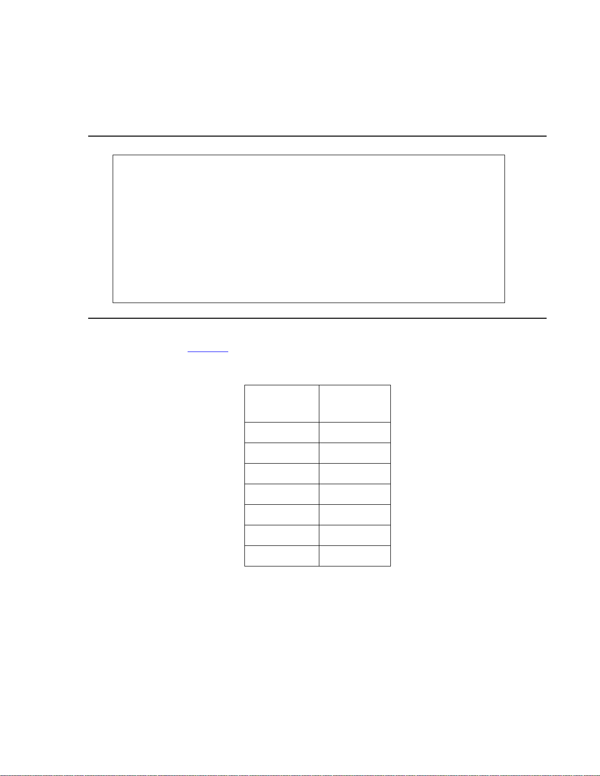
Set Date and Time
To set the date and time:
1. Enter set time and press Enter.
Figure 31: Date and Time screen
DATE AND TIME
DATE
Day of the Week: Tuesday Month: February
Day of the Month: 8 Year: 2000
TIME
Hour: 20 Minute: 30 Second: XX Type:
standard
Activate and Administer the System
Daylight Savings Rule: 0
2. In the Day of the Week: field, type the day of the week in English (Sunday through
Saturday). See Table 10
for English day of the week names.
Table 10: English Day of the Week Names
Day
Day Name
Number
1 Sunday
2 Monday
3 Tuesday
4 Wednesday
5 Thursday
6 Friday
7 Saturday
Issue 10 June 2005 83
Page 84

Installing and Cabling the Cabinets
Note:
3. In the Month: field, type the current month in English (January thr ough Dece mb er). See
Table 11
for English month names.
Table 11: English Month Names
Month
Month Name
Number
1 January
2 February
3March
4April
5May
6June
7July
8 August
9 September
10 October
11 November
12 December
4. In th e Day of the Month: field, type the day of month (1 through 31).
5. In the Year: field, type the current year.
6. In the Hour: field, type the current hour for a 24-hour clock.
7. In the Minute: field, type current minute (0 th rough 59). Seconds cannot be set.
8. If the area observes daylight savings, set the Daylight Savings Rule: field to the
appropriate rule.
Note: The default daylight savings rule i s 0, no daylight savings.
9. Press Enter to effect the changes.
84 Installation, Upgrades and Additions for Avaya CMC1 Media Gateways
Page 85

Circuit Pack Administration
!
After the equipment is ins t alled (incl uding circ uit p acks), th e circuit p acks must be administere d.
Refer to Administrator’s Guide for Avaya Communication Manager for more infor m a tion.
The following describes general administration information:
● Use the Circuit Packs form to administer circuit packs to carrier slots. The circuit packs
must be installed (or assigned using the Circuit Packs form) before administering voice
terminals, attendant consoles, or trunks.
● Each page of the form represents 1 carrier in the cabinet shown on the command line. All
carriers and slots appear even if they are not included in the hardware.
● It is not necessary to fill in the Circuit Packs form if the circui t packs are installed at the
time of administration.
● For initial installation, assign circuit packs to slots using the hardware configuration layout
record from the factory or Customer Ser vices Organiz ation. Do not arbit rarily a ssign circ uit
packs to slots.
● When a circuit pack in a slot differs from what has been administered on the form, a “#”
displays between the “Sfx” and “Name” fields.
Activate and Administer the System
Set System Maintenance Parameters
CAUTION:
CAUTION: To prevent unnecessary trouble tickets, do not enable the system alarms (Alarm
Origination feature) until all installation and administr ation procedures are
completed.
To set the system maintenance parameters:
1. Enter change system-parameters maintenance and press Enter.
2. Enter the alarm notification and scheduled maintenance information into each field on Page
1 of the form.
3. Enter the appropriate information on Page 2 of the form.
4. Press Enter when finished.
Administer the Attendant Console
If no attendant console is installed, proceed to Save Translations.
To administer the attendant console:
1. Enter display system-parameters country-options and press Enter. Verify the system’s
companding mode for its l o cal stations (usually, A-Law for Europe and mu-Law for North
America and Japan).
Issue 10 June 2005 85
Page 86

Installing and Cabling the Cabinets
Note:
Note:
2. If necessary, enter change terminal-parameters 603/302B1 to change the default
system-level parameters and audio levels for these terminals.
Note: For information about changing the default parameters and audio levels, refer to
DEFINITY Application Notes available through the ITAC (International Technical
Assistance Center).
3. Administer other forms listed under “Attendant Console” in Administrator’s Guide for Avaya
Communication Manager.
To administer an Avaya SoftConsole, see Administrator’s Guide for Avaya Communication
Manager.
Save Translations
To save translations:
1. Enter save translation and press Enter. This copies the current system translat ions onto
the translation card and takes about 10 minutes.
2. Remove the original translation card and replace with the backup card.
3. Repeat Step 1 for the backup translati on ca rd.
4. Remove the backup card and replace with the original translation card.
5. Label the backup card with the date and time of the backup and store in a secure place.
Add Translations
Refer to Administrator’s Guide for Avaya Communication Manager to add new terminals.
Install and Wire Telephone s and Trunks
Note: Only 1 pair of wires is available for emergency transfer, and 1 pair of wires is
available for attendant console power.
This section provides wiring examples of installation procedures. These are examples only a nd
actual wiring procedures may vary at each site.
The system can connect to all DTE terminals. The system can have RS-232 (or EIA-232) or
DCP interfaces.
All wiring pinouts for port circuit packs are in the tables at the end of thi s chapter.
86 Installation, Upgrades and Additions for Avaya CMC1 Media Gateways
Page 87

Refer to Figure 21: Example MDF Connections on pag e 63 for punch-down information for
302c
098
5
common circuit packs. The f igure shows the col ors of the punch- downs and is best viewed from
CD-ROM or on-line.
After installing the hardware, the data for the system and telephone features is administered.
These procedures are provided in Administrator’ s Guide for Avaya Communication Manager.
DCP, analog, and ISDN-BRI
The 302D Attendant Console describes a typical telephone conne ction. This information is
typical of the 603E, 84xx (4-wi re ), and 94x x telep hones. The atte ndant console al ways requir es
auxiliary (adjunct) power (-48 VDC). See Figure 32: 302D to Digital Line Circuit Pack Wiring
page 87. Only 1 console can be powered by the system through the AUX connector. The
primary console should be powered from the sy stem so it has the same power fai lure backup as
the system.
Install and Wire Telephones and Trunks
on
The maximum cabling distance for the console powered from the cabinet is 350 feet (100 m)
2
using 24 AWG (#5) (0.26 mm
) wire.
The general steps to connect a telephone are:
1. Choose a device to connect such as a 302D Attendant Console.
2. Choose the port circuit pack and its carrier and slot number, such as TN754C, Cabinet 1,
Carrier A, Slot 06.
3. Choose a port circuit on the port circuit pack, such as Port 05.
Figure 32: 302D to Digital Line Circuit Pack Wiring
TXT5
TXT
TXR
PXT
PXR
1
2
3
6
7
8
39
14
TXR
40
PXT5
15
PXR5
wireRPY012
Figure notes:
1. 302D attendant console
2. 4-wire digital line circuit pack
3. -48 VDC from adjunct power
4. Ground from adjunct power
4. Install cross-connect jumpers to wire the ter m inal to the port circuit pack. See Figure 32.
This pinout is for a 4-wire Digital Line circuit pack.
Issue 10 June 2005 87
Page 88

Installing and Cabling the Cabinets
Analog Station or 2-Wire Digital Station Example
This example is typical of the 2-wire digital stations,2-wire analog stations, analog CO trunks,
DID trunks, and external alarms. See Figure 33
Figure 33: 2500-Type Analog Telephone Wiring
.
Figure notes:
1. 2500-type analog station 2. 2-wire analog line circuit pack
To wire analog telephone equipment:
1. Choose a peripheral to connect (such as a 2-wire digital station).
2. Choose the port circuit pack to use and its carrier and slot number. For example, TN2183
Analog Line, Cabinet 1, Carrier C, Slot 1.
3. Choose a port circuit on the port circuit pack, for example port 3.
4. Install cross-connect jumpers to connect the pi ns from the 2-wire station to the appropriate
pins on the port circuit pack.
5. Administer using Administrator’s Guide for Avaya Communication Manager.
Analog Tie Trunk Example
Figure 34: Analog Tie Trunk Wiring
2T
3
R
2500wireRBP 040596
28
03
T3
R3
26
T1
R1
T11
R11
E1
M1
1
27
2
28
3
tie_wire RB P 040596
29
30
31
T2
4
R2
T12
R12
5
E2
6
M2
Figure notes:
1. External trunk or adapter 2. Tie trunk circuit pack
88 Installation, Upgrades and Additions for Avaya CMC1 Media Gateways
Page 89

To wire an analog tie trunk:
1. Before installing the Tie Trunk circuit pack, set the option switches as described in Chapter
2: Completing Installation and Cable Pinouts.
2. Install cross-connect jumpers to connect the pi ns from the Tie Trunk circuit pack to the
appropriate leads on the external t ie trunk. Names of the tie trunk leads must be determined
from the manufacturer or supplier of the external trunk circuit. The example in Figure 34
shows a DEFINITY System tie trunk connected to a DEFINITY System tie trunk.
3. Administer on the Trunk Group Screen. See Administrator’s Guide for Avaya
Communication Manager.
Digital Tie Trunk Example
Figure 35: Digital Tie Trunk Wiring
Install and Wire Telephones and Trunks
Figure notes:
1. Ex te rn al tr u n k
2. DS1 interface circuit pack, position 1C06
3. LO
4. LO (Balanced output pair)
5. L
I
6. LI (Balanced input pair)
To wire a digital tie trunk:
1. Before installing the DS1 Interface circui t pack, set the opt ion switches according to Chapter
2: Completing Installation and Cable Pinouts.
2. Install cross-connect jumpers to connect the pi ns from the digital trunk circuit p ack to
appropriate pins on the external digital trunk.
3. Administer the DS1 Interface circuit pack on the DS1 and Trunk Group Screens. See
Administrator’s Guide for Avaya Communication Manager.
Issue 10 June 2005 89
Page 90

Installing and Cabling the Cabinets
Note:
DS1 Tie Trunk Example
DS1 tie trunks provide a 1.544 Mbps (T1) or 2.048 Mbps (E1) digital data service between 2
collocated systems or between the system and a data network. The fol lowi ng cables can be
used:
● C6C connector cable — 50-foot (15.2 m) shielded cable wit h a 50- pin male connect or on
1 end and a 15-pin male connecto r on the other end. Use to conn ect a DS1 tie t runk circ uit
pack to a Channel Service Unit.
● C6D connector cable — 50-foot (15.2 m) shielded cable wit h a 50- pin male connect or on
each end. Use to connect a DS1 tie trunks in collocated cabinets.
● C6E connector cable — 100-foot (30.5 m) shielded cable with a 50-pin male connector
on 1 end and a 50-pin female connector on the other end. Use as an “extension” cable
between the DS1 tie trunk circuit pack and other connector cables.
● C6F connector cable — 50-foot (15.2 m) shielded cab le with a 50-pin male connector on
1 end and a 3 inch (7.62 cm) st ub on the other end. Use to connect the DS1 t ie trunk circ uit
pack to channel multiplexers requiring hardwired connections. See Table 12
Table 12: Pinout of C6F Cable
for a pinout.
Wire Color Lead Designation Pin Number
White/Green L
Green L
White/Brown LO 48
Brown LO (Hi gh Side) 23
White/Slate LBACK2 49
Slate LBACK1 24
Collocated DS1 Tie Trunks
Two DS1 tie trunk circuit packs can be in collocated systems. A DS1 tie trunk circuit pack in 1
system can connect to a DS1 tie trunk in another system. Use a C6D cable if the distance is
less than 50 feet (15.24 m). If the distance is greater than 50 feet (15.24 m), use a C6E cable.
Note: The maximum distance between cabinets is 1310 feet (399.3 m).
I (High Side) 47
I 22
90 Installation, Upgrades and Additions for Avaya CMC1 Media Gateways
Page 91

Install and Wire Telephones and Trunks
DS1 Tie Trunks Using T1 Channel Service Unit
Figure 36 shows a DS1 tie trunk connected to an external T1 Channel Service Unit (CSU). A
120A2 enhanced Integrated Channel Servic e Unit (I CSU) can be used i n pl ace of a T1 ext ernal
CSU. The CSU or ICSU interfaces the DS1 tie trunks with the 1.544 Mbps digital facility.
Contact your Avaya Inc. repr esentative for maximum cabling distances.
Figure 36: Typical Connections to Channel Service Unit
Figure notes:
1. To DS1 tie trunk circuit pack
2. C6C cable (If distance is over 50 feet
(15.24 m), use C6E cable.)
3. T1 external CSU or 120A2 ICSU
4. Tip (T)
3-Pair and 4-Pair Modularity
Figure 37 shows 3-pair and 4-pair modularity from the port cir cuit pack to the voice or data
terminal. Most terminals connect to an information outlet (modular jack) installed at the work
location.
5. Ring (R)
6. Tip 1(T1)
7. Ring1 (R1)
8. 1.544 Mbps T1 interface
9. To T1 carrier
Issue 10 June 2005 91
Page 92

Installing and Cabling the Cabinets
!
Figure 37: 3-Pair and 4-Pair Modularity
26
1
27
2
28
3
1
2
3
4
5
6
Figure notes:
1. Port circ u it pack
2. 25-pair connector pins (3-pair modularity)
3. MDF pins (3-pair modularity)
4. Input to information outlet (4-pair modularity)
Install Attendant Console — Optional
1
2
3
4
5
6
77
88
1
2
3
4
5
6
widf3pm RPY012098
1
2
3
4
5
6
7
8
5. Output from information
outlet (4-pair modularity)
6. Voice or data terminal pins
7. Adjunct power
To install a DCP attendant console:
1. Position the attendant console in the desired location and connect the modular cord to the
information outlet.
2. Install labels per the Attendant Console form and Display Module form assignments.
3. Install a Digital Line circui t pack in the assigned carrier slot (if required).
4. Administer the Attendant Console forms in Administ rator’ s Guide for Avaya Communicat ion
Manager.
Hard-Wire Bridging
CAUTION:
CAUTION: Bridging or paralleling these endpoints can cause electrical damage to the
consoles or cause the circuit pack to remove power from the consoles.
Analog type hard-wire bridging is not allowed for 4-wire (only) DCP endpoints. This is because
hard-wire bridging provides n o way of combining the digital output of 2 bridged DCP sets. Also,
a bridged endpoint causes the added load to degrade the DCP signal.
92 Installation, Upgrades and Additions for Avaya CMC1 Media Gateways
Page 93

Install and Wire Telephone Power Supplies
Dual Wiring of 2-Wire and 4-Wire Endpoints
Do not simultaneously wire a 2-wire and 4-wire endpoint to the same equipment location in an
MDF, even though they connect to different colo red wire pair s. The system uses sep arate circui t
packs to interface 2- and 4-wire endpoints, and none are capable of interfacing both.
Install 26B1 Selector Console — Optional
To install a 26B1 selector console:
1. Connect the supplied 3-foot (0.9 m) D8AC cable to the modular jack on the bottom of the
26B1 Selector Console.
2. Route the cable to the attendant console and connect to the DXS/BLF jack.
3. Attach labels according to the Attendant Console form.
4. Administer the console using Administrator’s Guide for Avaya Communication Manager.
Administer IP Stations and Trunks
For complete information on administ ering I P st ati ons and tru nks, see Administrator’s Guide for
Avaya Communication Manager.
Install and Wire Telephone Power Supplies
This section provides information and wiring exampl es of installation procedures for various
telephone and console power supplies. These are examples only and actual wiring procedures
may vary at each site.
The power is provided to telephones or consoles either locally or centrally.
Centrally located power supplies include
● 1145B2 Power Supply on page 96
● 1152A1 Mid-Span Power Distribution Unit on page 106
● P333T-PWR Power over Ethernet Stackable Switch on page 110
Local power supplies include
● 1151B1 and 1151B2 Power Supplies on page 113
Issue 10 June 2005 93
Page 94

Installing and Cabling the Cabinets
8
Typical Adjunct Power Connections
The following section describes typical adjunct power connections.
Adjunct Power Adapter
The 400B2 adapter is convenient for connecting local -48 VDC power to a modular plug. See
Figure 38
Figure 38: 400B2 Adapter Connecting to a Modular Plug
.
Figure notes:
1. Surface-mounted information outlet
2. To individual power unit (such as 1 15 1B or 1151B2)
3. 400B2 adapter
Adjunct power can be provided from the equipment room or equipment clos et with 1145B power
unit. The AUX connector (J1) on the processor interface cable can provide power for 1
attendant console. See Table 36: Processor Interface Cable Pinout
Adjunct power can be provided locally at the telephone or console by the 1151B or 1151B2
Power Supply.
Adjunct Power Connections End-to-End
Figure 39 shows typical connection locations for adjunct power.
r749428 RPY01209
4. To telephone
5. Destination service access
point (DSAP) power cord
on page 165.
94 Installation, Upgrades and Additions for Avaya CMC1 Media Gateways
Page 95

Figure 39: Example Adjunct Power Connections
Note:
Install and Wire Telephone Power Supplies
2
1
3
Figure notes:
1. Typical display telephone
2. Individual power supply (Such as
1151B) (Not used if item 14 is used)
3. 400B2 adapter
4. Information outlet (modular jack)
5. 4-pair D-Inside Wire (DIW) cable
6. Satellite site or adapter location
7. 25-pair D-Inside Wire (DIW) cable
13
6
4
5
14
8
7
14
10
9
cydmapwr EWS 052898
12
11
8. Station side of MDF
9. 100P6A patch cord or jumpers
10. System side of MDF
11. 25-pair cable to digital line circuit pack
12. Equipment room
13. Satellite location
14. Bulk power supply (Such as 1145B). Install at
satellite location or equipment room (not both).
Auxiliary Power for an Attendant Console
The nonessential functions of an attendant console and its optional 26A1 or 24A1 selector
console derive power from an auxiliary power source. Provide auxi liary power for an attendant
console through this cable so the console remains fully operational during short power outages.
Note: Only 1 console can derive auxiliary power from the system and through the
auxiliary cable located in the trunk/auxiliary field.
A console’s maximum distance from its auxiliary power source is:
● 800 feet (244 m) for a 302A1
● 350 feet (107 m) for a 301B1 and 302D
An attendant console can also derive auxiliary power from:
● Individual 1151B or 1 151B2 power supply
● MSP-1 power supply
● 258A-type adapters
● Bulk power supplies such as the 1145A1
Issue 10 June 2005 95
Page 96

Installing and Cabling the Cabinets
Note:
Local and Phantom Power
An attendant console’s maximum distance from the system is limited.
See Table 13
.
Table 13: Attendant Console Cabling Distances
Enhanced Attendant
Console (302D)
With Selector Console
Phantom powered 800 244 500 152
Locally powered 5000 1524 3400 1037
Without Selector
Console
Phantom powered 1400 427 900 274
Locally powered 5000 1524 3400 1037
1145B2 Power Supply
The 1145B2 closet power arrangement provides an uninterruptible -48 VDC power source with
battery and 1146B2 distribution unit for ISDN/DCP, terminal equipment, adjuncts, and other
customer-supplied equipment. During AC power inter ruptions, batteries automatically provide
power to the load.
24 AWG Wire
2
(0.26 mm
)
26 AWG Wire
(0.14 mm2)
Feet Meters Feet Meters
Note: Before you begin, read this Important Warning for 1145B2 Power Supply on
page 97.
Perform these tasks in order:
1. Install the Wall-Mounting Plates
2. Mount the 1146B2 Power Distribution Unit
3. Install the Battery Mounting/Wiring
4. Install the Expanded Power Distribution Unit
5. Power Up and Test the Power Supply
6. Wire the 1146B2 Power Dist ribution Unit
7. Reset LEDs on Power Distribution Unit
96 Installation, Upgrades and Additions for Avaya CMC1 Media Gateways
on page 101
on page 101
on page 102
on page 102
on page 103
on page 104
on page 106
Page 97

Important Warning for 1145B2 Power Supply
!
WARNING:
WARNING: Important Sa fe ty Instruction s fo llo w.
When operating this equipment, basic safety precauti ons must be fo llowed to r educe th e risk of
fire, electric shock and personal injury, including the following:
● Read and understand all instructions.
● Do not attach the power supply cord to building surfaces.
● For continued back-up protection and battery reliabilit y, replace batteries every four years.
● Follow all warnings and instructions marked on the products.
● Clean products only with a dry rag.
● Do not use this product near water.
● For mounting security, follow all installation instructions when mounting product.
● Openings on top and bottom of power unit are provided for ventilation. Do not block or
cover these openings. Do not exceed recommended environmental temperatures.
Install and Wire Telephone Power Supplies
● Operate these products only from the type of power source indicated on the product
labels.
● The power unit is equipped with a 3-wire grounding plug; a plug havi ng a thi rd (groun ding )
pin. This plug will only fit into a grounding power outlet. This is a safety feature. If you are
unable to insert the plug into the outlet , contact an electrician to replace the outlet. Do not
defeat the safety purpose of the grounding plug.
● Do not allow anything to rest on or spill into the products.
● To reduce risk of fire and electrical shock, do not overload power outlets.
● Never push objects of any kind through the power supply or distribution unit slots as they
may touch dangerous voltage points or short out parts that could result in a risk of fire or
electrical shock.
● T o reduce ri sk of e lectr ic shock, do not disassembl e these pr oducts. Return t hem for r epai r
when needed. Opening or removing covers may expose you to dangerous voltages or
other risks. Incorrect reassembly can caus e elect ri c shock when the products are
subsequently used.
● Power down the power unit (see label on power unit on how to do this) and refer servicing
under the following conditions:
● If liquid has been spilled into any of the product s
● If any of the products have been exposed to water
● If any of the products do not operate normally
● If any of the products have been dropped or damaged
● If any of the products exhibit s a change in perf ormance
Issue 10 June 2005 97
Page 98

Installing and Cabling the Cabinets
Note:
● Do not attempt to recharge batteries on your own. The batteries may leak corrosive
electrolyte or explode. The 1145B2 power unit recharges the batteries safely.
● Remove the batteries if the power unit will not be used for a long period of time (several
months or more) since during this time the battery may leak.
● Discard discharged batteries as soon as possible. Discharg ed batteries are more likely to
leak.
● Do not store batteries in high temperature areas. Batteries stored in a cold environment
should be protected from condensation during storage and warming. Batteries should be
stabilized at room t e mperature prior to use af ter cold storage. Do not install batteries if the
manufacturing date on the label indicates that the batt e ries are more than six months old.
Mounting the 1145B2/1146B2 Power Supply
1145B2/1146B2 Mounting Arrangement on page 99 shows how the standard power supply and
wall-mounting plates fit together. Expanded Power Distribution Unit
expanded power supply components (power distribution unit and “T” cable).
A manual switch on the distribution unit allows the user to redirect reserve power to outputs 1
through 32 so all outputs are provided battery reserve power or to outputs 1 through 8 to
provide high power above 6.25 watts.
on page 100 shows the
Note: The switch must be set to the 1-32 position.
The 1145B22/1146B2 is a -48 V power supply with 275 watts total output. Each output circuit is
current limited by a Polymer Positive Temperature Coefficient Resistance Device (PTC) that
limits the maximum output to 12 watts. Each 1146B2 output has an LED to indicate the st atus of
the PTC. If the LED is on, the PTC has a short on that power pair.
Not all outputs can simultaneously provide 12 watts. The average power per output cannot
exceed 8.6 watts (275/32 = 8.6). The 1145B22 is designed to power one ISDN terminal or DCP
adjunct per output. The maximum number of terminals or adjuncts is 32 at less than or equal to
6.25 watts each. The 1145B22 is required for installations outside the United States.
Auxiliary power (local or bulk) is always required for the following:
● Attendant Console 302D
● PassageWay adapter interface
98 Installation, Upgrades and Additions for Avaya CMC1 Media Gateways
Page 99

Figure 40: 1145B2/1146B2 Mounting Arrangement
1149 Battery
On Battery Reserve
1145 Power Unit
Charging Battery
Output Power On
Install and Wire Telephone Power Supplies
-48V -48V
1
2
3
4
5
6
7
8
9
10
11
12
13
14
15
16
RTN RTN
UnitNo.
Connected To:
17
18
19
20
21
22
23
24
25
26
27
28
29
30
31
32
Figure notes:
1. Wall Mounting Plate
2. Battery (1149B Shown)
3. 1146B2 Power Distribution Unit
4. 1145B2 Power Unit
1-8
1-32
0003_1 PDH 062596
5. Power Cable
6. Nonswitched Outlet (120 VAC, 20 amp
or 230 VAC, 15 amp)
7. Battery Backup Switch Setting
Issue 10 June 2005 99
Page 100

Installing and Cabling the Cabinets
Figure 41: Expanded Power Distribution Unit
1149 Battery
1145 PowerUnit
On Battery Reserve
Charging Battery
Output Power On
-48V -4 8V
1
RTN RTN
2
3
4
5
6
7
8
9
10
11
12
13
14
15
16
-48V -48V
1
RTN RTN
2
3
4
5
6
7
8
9
10
11
12
13
14
15
16
0004_1 PDH 062596
UnitNo.
ConnectedTo:
UnitN o.
ConnectedTo:
17
18
19
20
21
22
23
24
25
26
27
28
29
30
31
32
17
18
19
20
21
22
23
24
25
26
27
28
29
30
31
32
Figure notes:
1. Wall Mounting Plate
4. First 1146B2 Power
2. Second 1146B2 Power Distribution Unit
3. “T” Cable (H600-347-G7)
5. 1145B2 Power Unit
100 Installation, Upgrades and Additions for Avaya CMC1 Media Gateways
Distribution Unit
 Loading...