

Page 1

Avaya CallPilot® 703t Server Maintenance
and Diagnostics
5.0
NN44200-702, 01.09
December 2010
Page 2

© 2010 Avaya Inc.
All Rights Reserved.
Notice
While reasonable efforts have been made to ensure that the
information in this document is complete and accurate at the time of
printing, Avaya assumes no liability for any errors. Avaya reserves the
right to make changes and corrections to the information in this
document without the obligation to notify any person or organization of
such changes.
Documentation disclaimer
“Documentation” means information published by Avaya in varying
mediums which may include product information, operating instructions
and performance specifications that Avaya generally makes available
to users of its products. Documentation does not include marketing
materials. Avaya shall not be responsible for any modifications,
additions, or deletions to the original published version of
documentation unless such modifications, additions, or deletions were
performed by Avaya. End User agrees to indemnify and hold harmless
Avaya, Avaya's agents, servants and employees against all claims,
lawsuits, demands and judgments arising out of, or in connection with,
subsequent modifications, additions or deletions to this documentation,
to the extent made by End User.
Link disclaimer
Avaya is not responsible for the contents or reliability of any linked Web
sites referenced within this site or documentation provided by Avaya.
Avaya is not responsible for the accuracy of any information, statement
or content provided on these sites and does not necessarily endorse
the products, services, or information described or offered within them.
Avaya does not guarantee that these links will work all the time and has
no control over the availability of the linked pages.
Warranty
Avaya provides a limited warranty on its Hardware and Software
(“Product(s)”). Refer to your sales agreement to establish the terms of
the limited warranty. In addition, Avaya’s standard warranty language,
as well as information regarding support for this Product while under
warranty is available to Avaya customers and other parties through the
Avaya Support Web site:
you acquired the Product(s) from an authorized Avaya reseller outside
of the United States and Canada, the warranty is provided to you by
said Avaya reseller and not by Avaya.
Licenses
THE SOFTWARE LICENSE TERMS AVAILABLE ON THE AVAYA
WEBSITE,
APPLICABLE TO ANYONE WHO DOWNLOADS, USES AND/OR
INSTALLS AVAYA SOFTWARE, PURCHASED FROM AVAYA INC.,
ANY AVAYA AFFILIATE, OR AN AUTHORIZED AVAYA RESELLER
(AS APPLICABLE) UNDER A COMMERCIAL AGREEMENT WITH
AVAYA OR AN AUTHORIZED AVAYA RESELLER. UNLESS
OTHERWISE AGREED TO BY AVAYA IN WRITING, AVAYA DOES
NOT EXTEND THIS LICENSE IF THE SOFTWARE WAS OBTAINED
FROM ANYONE OTHER THAN AVAYA, AN AVAYA AFFILIATE OR AN
AVAYA AUTHORIZED RESELLER; AVAYA RESERVES THE RIGHT
TO TAKE LEGAL ACTION AGAINST YOU AND ANYONE ELSE
USING OR SELLING THE SOFTWARE WITHOUT A LICENSE. BY
INSTALLING, DOWNLOADING OR USING THE SOFTWARE, OR
AUTHORIZING OTHERS TO DO SO, YOU, ON BEHALF OF
YOURSELF AND THE ENTITY FOR WHOM YOU ARE INSTALLING,
DOWNLOADING OR USING THE SOFTWARE (HEREINAFTER
REFERRED TO INTERCHANGEABLY AS “YOU” AND “END USER”),
AGREE TO THESE TERMS AND CONDITIONS AND CREATE A
BINDING CONTRACT BETWEEN YOU AND AVAYA INC. OR THE
APPLICABLE AVAYA AFFILIATE (“AVAYA”).
HTTP://SUPPORT.AVAYA.COM/LICENSEINFO/ ARE
http://support.avaya.com. Please note that if
Copyright
Except where expressly stated otherwise, no use should be made of
materials on this site, the Documentation, Software, or Hardware
provided by Avaya. All content on this site, the documentation and the
Product provided by Avaya including the selection, arrangement and
design of the content is owned either by Avaya or its licensors and is
protected by copyright and other intellectual property laws including the
sui generis rights relating to the protection of databases. You may not
modify, copy, reproduce, republish, upload, post, transmit or distribute
in any way any content, in whole or in part, including any code and
software unless expressly authorized by Avaya. Unauthorized
reproduction, transmission, dissemination, storage, and or use without
the express written consent of Avaya can be a criminal, as well as a
civil offense under the applicable law.
Third-party components
Certain software programs or portions thereof included in the Product
may contain software distributed under third party agreements (“Third
Party Components”), which may contain terms that expand or limit
rights to use certain portions of the Product (“Third Party Terms”).
Information regarding distributed Linux OS source code (for those
Products that have distributed the Linux OS source code), and
identifying the copyright holders of the Third Party Components and the
Third Party Terms that apply to them is available on the Avaya Support
Web site:
Trademarks
The trademarks, logos and service marks (“Marks”) displayed in this
site, the Documentation and Product(s) provided by Avaya are the
registered or unregistered Marks of Avaya, its affiliates, or other third
parties. Users are not permitted to use such Marks without prior written
consent from Avaya or such third party which may own the Mark.
Nothing contained in this site, the Documentation and Product(s)
should be construed as granting, by implication, estoppel, or otherwise,
any license or right in and to the Marks without the express written
permission of Avaya or the applicable third party.
Avaya is a registered trademark of Avaya Inc.
All non-Avaya trademarks are the property of their respective owners,
and “Linux” is a registered trademark of Linus Torvalds.
Downloading Documentation
For the most current versions of Documentation, see the Avaya
Support Web site:
Contact Avaya Support
Avaya provides a telephone number for you to use to report problems
or to ask questions about your Product. The support telephone number
is 1-800-242-2121 in the United States. For additional support
telephone numbers, see the Avaya Web site:
Japan Denan statement
The following applies to server models 1006r, 1005r, 703t, and 1002rp:
http://support.avaya.com/Copyright.
http://support.avaya.com.
http://support.avaya.com.
2 Avaya CallPilot® 703t Server Maintenance and Diagnostics December 2010
Page 3
Japan VCCI statement
The following applies to server models 1006r, 1005r, 703t, 201i, and
1002rp:
This is a Class A product based on the standard of the Voluntary Control
Council for Interference by Information Technology Equipment (VCCI).
If this equipment is used in a domestic environment, radio disturbance
may occur, in which case, the user may be required to take corrective
action.
Avaya CallPilot® 703t Server Maintenance and Diagnostics December 2010 3
Page 4

4 Avaya CallPilot® 703t Server Maintenance and Diagnostics December 2010
Page 5

Contents
Chapter 1: Customer service..................................................................................................11
Getting technical documentation.....................................................................................................................11
Getting product training...................................................................................................................................11
Getting help from a distributor or reseller........................................................................................................11
Getting technical support from the Avaya Web site........................................................................................12
Chapter 2: About this guide...................................................................................................13
In this chapter..................................................................................................................................................13
Maintenance and diagnostics overview..........................................................................................................13
Replacement parts..........................................................................................................................................13
Preparing for maintenance activities...............................................................................................................14
Customer Documentation Map.......................................................................................................................14
Chapter 3: Troubleshooting your Avaya CallPilot® system................................................19
In this chapter..................................................................................................................................................19
Overview.........................................................................................................................................................19
Interpreting front panel LEDs..........................................................................................................................20
LED locations..................................................................................................................................................20
Network LED states........................................................................................................................................21
Hard drive LED states.....................................................................................................................................22
Power/sleep LED states..................................................................................................................................23
System status LED..........................................................................................................................................23
Tape drive LED states.....................................................................................................................................24
CD-ROM drive LED states..............................................................................................................................25
Interpreting rear panel LEDs...........................................................................................................................25
MPB96 DS30 connection link LED states.......................................................................................................25
Blue LED.........................................................................................................................................................26
Interpreting internal LEDs...............................................................................................................................26
MPB96 LED states..........................................................................................................................................26
PCI FPGA Done LED (closest to the I/O card bracket)...................................................................................27
DSP FPGA Done LED....................................................................................................................................27
CTbus FPGA Done LED (furthest from the I/O card bracket).........................................................................27
RAID controller LED states.............................................................................................................................27
To check if RAID board is working properly....................................................................................................27
Interpreting POST diagnostics........................................................................................................................28
Types of beep codes.......................................................................................................................................28
SCSI controller diagnostics.............................................................................................................................30
BIOS initialization............................................................................................................................................30
RAID controller diagnostics.............................................................................................................................30
What to do when the server fails to boot into service......................................................................................31
When the 703t server does not boot and there are no audible beeps............................................................31
When the 703t server does not boot and the system board LED is red..........................................................32
When the 703t server does not boot and makes audible beeps.....................................................................32
If beeps are short............................................................................................................................................32
If beeps are long.............................................................................................................................................33
When the 703t server boots to the operating system and makes audible beeps............................................33
When the 703t server boots to the operating system but does not boot to CallPilot.......................................33
Avaya CallPilot® 703t Server Maintenance and Diagnostics December 2010 5
Page 6

Chapter 4: Using Windows online diagnostic tools.............................................................35
In this chapter..................................................................................................................................................35
Overview.........................................................................................................................................................35
Operating system Event Viewer......................................................................................................................35
TCP/IP diagnostics..........................................................................................................................................36
chkdsk utility....................................................................................................................................................36
Viewing event logs..........................................................................................................................................36
Types of event logs.........................................................................................................................................37
To use the operating system Event Viewer.....................................................................................................37
Using TCP/IP diagnostic tools.........................................................................................................................39
The ipconfig command....................................................................................................................................40
Ipconfig default................................................................................................................................................40
Ipconfig command syntax...............................................................................................................................40
To run the ipconfig command from Windows..................................................................................................40
The ping command.........................................................................................................................................41
Ping command syntax.....................................................................................................................................41
To run the ping command from Windows........................................................................................................41
The tracert command......................................................................................................................................42
How tracert works...........................................................................................................................................42
Tracert syntax..................................................................................................................................................42
To run the tracert command from Windows....................................................................................................43
The arp command...........................................................................................................................................43
Arp command syntax......................................................................................................................................43
To run the arp command from Windows.........................................................................................................44
The nbtstat command.....................................................................................................................................45
Nbtstat command syntax.................................................................................................................................45
To run the nbtstat command from Windows....................................................................................................46
The netstat command.....................................................................................................................................46
Netstat command syntax.................................................................................................................................46
To run the netstat command from Windows....................................................................................................47
Using the chkdsk utility....................................................................................................................................47
Chkdsk utility syntax........................................................................................................................................47
To run the chkdsk utility from Windows...........................................................................................................48
Chapter 5: Using serial port diagnostic tools.......................................................................49
In this chapter..................................................................................................................................................49
Overview.........................................................................................................................................................49
Shutting down services...................................................................................................................................49
Service to stop for COM 1 testing...................................................................................................................50
Services to stop for COM 2 testing.................................................................................................................50
Net Stop command.........................................................................................................................................50
Net Stop command syntax..............................................................................................................................50
To invoke the Net Stop command from Windows...........................................................................................51
Conducting TSTSERIO tests..........................................................................................................................51
TSTSERIO command syntax..........................................................................................................................51
TSTSERIO internal loopback diagnostic subtests..........................................................................................52
To invoke the TSTSERIO /P command from Windows...................................................................................52
TSTSERIO external loopback plug subtests...................................................................................................53
To invoke the TSTSERIO /S command from Windows...................................................................................53
Conducting TSTSERIO tests with the loopback plug......................................................................................53
9-pin connector plug........................................................................................................................................54
6 Avaya CallPilot® 703t Server Maintenance and Diagnostics December 2010
Page 7

Restarting services..........................................................................................................................................54
Service to restart after COM 1 testing.............................................................................................................54
Services to restart after COM 2 testing...........................................................................................................54
Net Start command.........................................................................................................................................55
To invoke the Net Start command from Windows...........................................................................................55
Chapter 6: Using CallPilot Manager to monitor hardware...................................................57
In this chapter..................................................................................................................................................57
Understanding fault management...................................................................................................................57
Event processing.............................................................................................................................................58
Alarm notification.............................................................................................................................................58
Component dependencies..............................................................................................................................58
Detecting hardware problems.........................................................................................................................59
Alarm Monitor..................................................................................................................................................59
About alarms...................................................................................................................................................59
To investigate using the Alarm Monitor...........................................................................................................60
Event Browser.................................................................................................................................................60
About events...................................................................................................................................................60
To investigate using the Event Browser..........................................................................................................61
Channel and Multimedia Monitors...................................................................................................................61
Disabling call channels....................................................................................................................................62
The Maintenance page...................................................................................................................................62
What the Maintenance page provides.............................................................................................................62
Maintenance activities for each component....................................................................................................63
Viewing component states..............................................................................................................................64
Component states...........................................................................................................................................64
Alert icons.......................................................................................................................................................65
To view the state of a hardware component....................................................................................................65
Starting and stopping components..................................................................................................................66
Stop versus Courtesy stop..............................................................................................................................66
Courtesy stop..................................................................................................................................................66
Stop.................................................................................................................................................................67
Components that can be started and stopped................................................................................................67
To start or stop a component...........................................................................................................................67
Running integrated diagnostics.......................................................................................................................68
Before you begin.............................................................................................................................................69
Diagnostic tests available for each component...............................................................................................69
Components that have diagnostic tests available...........................................................................................69
If a diagnostic test fails or cannot be run.........................................................................................................69
To run a diagnostic test...................................................................................................................................70
Viewing the last diagnostic results..................................................................................................................71
To view the last diagnostics result...................................................................................................................71
Working with the Multimedia Monitor..............................................................................................................72
To view or work with multimedia channel states.............................................................................................72
Working with the Channel Monitor..................................................................................................................73
To view or work with call channel states.........................................................................................................73
Chapter 7: Using Avaya CallPilot® system utilities.............................................................75
In This chapter................................................................................................................................................75
Overview.........................................................................................................................................................75
Accessing the system utilities.........................................................................................................................76
Diagnostics Tool..............................................................................................................................................76
Avaya CallPilot® 703t Server Maintenance and Diagnostics December 2010 7
Page 8

To access the Diagnostics Tool.......................................................................................................................76
To enable startup diagnostics..........................................................................................................................76
To disable startup diagnostics.........................................................................................................................77
PEP Maintenance utility..................................................................................................................................77
To access the PEP Maintenance utility...........................................................................................................77
To view a list of all installed PEPs...................................................................................................................77
Session Trace.................................................................................................................................................78
To access the session trace tool.....................................................................................................................78
To find a session.............................................................................................................................................79
System Monitor...............................................................................................................................................79
To access the System Monitor........................................................................................................................80
Channel Monitor tab........................................................................................................................................80
CallPilot services.............................................................................................................................................81
DSPs...............................................................................................................................................................82
DS30X links.....................................................................................................................................................82
System Info tab...............................................................................................................................................82
Legend/Help tab..............................................................................................................................................83
Chapter 8: Replacing basic chassis components................................................................85
In this chapter..................................................................................................................................................85
Preparing the server for hardware maintenance.............................................................................................85
To disconnect the power and peripheral device cables...................................................................................86
Removing the side cover.................................................................................................................................88
To remove the side cover................................................................................................................................88
Removing and replacing the upper fan holder foam.......................................................................................90
To remove the upper fan holder foam.............................................................................................................91
To replace the upper fan holder foam.............................................................................................................91
Replacing the side cover.................................................................................................................................91
To replace the side cover................................................................................................................................92
Cooling fans description..................................................................................................................................93
Replaceable fan locations...............................................................................................................................94
Fan labels........................................................................................................................................................96
Replacing a front system fan...........................................................................................................................96
To remove a front system fan..........................................................................................................................97
Replacing a rear system fan...........................................................................................................................99
To remove a rear system fan...........................................................................................................................99
Replacing the processor fan.........................................................................................................................101
To remove the processor fan.........................................................................................................................101
Chapter 9: Replacing media drives......................................................................................105
SCSI and IDE drive cabling...........................................................................................................................105
Cabling diagram............................................................................................................................................105
Replacing a faulty hard drive.........................................................................................................................106
Hard drive description...................................................................................................................................107
SCSI drive cabling.........................................................................................................................................107
Hard drive configuration................................................................................................................................107
Filler panels and EMI shields........................................................................................................................108
To remove a hard drive from the server........................................................................................................109
To install the hard drive..................................................................................................................................111
Replacing the tape drive................................................................................................................................113
Filler panels and EMI shields.........................................................................................................................113
Tape drive configuration................................................................................................................................113
8 Avaya CallPilot® 703t Server Maintenance and Diagnostics December 2010
Page 9

To remove the tape drive...............................................................................................................................114
To install a replacement tape drive................................................................................................................115
Replacing the CD-ROM drive........................................................................................................................117
To remove the CD-ROM drive.......................................................................................................................117
To install a replacement CD-ROM drive........................................................................................................118
Replacing the floppy disk drive......................................................................................................................119
To remove the floppy disk drive.....................................................................................................................120
To install a replacement floppy disk drive......................................................................................................121
Chapter 10: RAID operations................................................................................................125
In this chapter................................................................................................................................................125
RAID overview..............................................................................................................................................125
RAID configuring and splitting.......................................................................................................................125
Verifying the RAID firmware..........................................................................................................................126
To verify the RAID firmware version..............................................................................................................126
To upgrade or downgrade the RAID firmware...............................................................................................127
Configuring RAID using LSI Elite 1600 controller and Ctrl+M.......................................................................128
To configure an LSI Elite 1600 RAID system................................................................................................128
Replacing the LSI1600 or LSI320-2 card with LSI320-2...............................................................................130
Verifying consistency on the drives...............................................................................................................131
To perform a consistency check....................................................................................................................132
RAID splitting................................................................................................................................................132
Full data backup............................................................................................................................................133
To split the RAID...........................................................................................................................................133
Perform a CallPilot software upgrade...........................................................................................................134
To synchronize the RAID after a successful upgrade...................................................................................134
To synchronize RAID after an unsuccessful upgrade...................................................................................135
Task summary for configuring RAID..............................................................................................................136
Task summary for RAID splitting...................................................................................................................137
Chapter 11: Replacing or adding voice processing boards..............................................141
In thischapter.................................................................................................................................................141
DSP numbering and location........................................................................................................................141
DSP numbering on MPB96 boards...............................................................................................................141
Replacing MPB96 boards.............................................................................................................................142
Requirements................................................................................................................................................143
To replace an MPB96 board..........................................................................................................................144
Chapter 12: Working with DIMMs and the CPU..................................................................147
In this chapter................................................................................................................................................147
Replacing or adding baseboard DIMMs........................................................................................................147
DIMM sizes and compatibility........................................................................................................................147
To remove baseboard DIMMs.......................................................................................................................148
To install baseboard DIMMs..........................................................................................................................149
Replacing the CPU........................................................................................................................................150
CPU replacement package contents.............................................................................................................150
To remove the faulty CPU.............................................................................................................................151
To install a new CPU.....................................................................................................................................154
Chapter 13: Working with the Avaya CallPilot® server BIOS............................................161
In this chapter................................................................................................................................................161
Overview.......................................................................................................................................................161
Avaya CallPilot® 703t Server Maintenance and Diagnostics December 2010 9
Page 10

BIOS release.................................................................................................................................................161
To determine the BIOS release.....................................................................................................................161
BIOS settings................................................................................................................................................162
Main..............................................................................................................................................................162
Advanced......................................................................................................................................................163
Security.........................................................................................................................................................164
Server............................................................................................................................................................164
Boot...............................................................................................................................................................165
Updating and configuring the BIOS...............................................................................................................166
BIOS update availability................................................................................................................................166
To configure the BIOS...................................................................................................................................166
Recovering from corrupted CMOS and BIOS...............................................................................................167
To recover from a corrupted CMOS..............................................................................................................168
Chapter 14: 703t description reference...............................................................................171
In this appendix.............................................................................................................................................171
Server features..............................................................................................................................................171
Front panel features......................................................................................................................................172
Rear panel diagram.......................................................................................................................................174
Slot assignments...........................................................................................................................................176
Slot definition and numbering........................................................................................................................176
IRQ mapping table........................................................................................................................................177
Index.......................................................................................................................................179
10 Avaya CallPilot® 703t Server Maintenance and Diagnostics December 2010
Page 11

Chapter 1: Customer service
Visit the Avaya Web site to access the complete range of services and support that Avaya provides. Go
to www.avaya.com or go to one of the pages listed in the following sections.
Navigation
Getting technical documentation on page 11
•
• Getting product training on page 11
• Getting help from a distributor or reseller on page 11
Getting technical support from the Avaya Web site on page 12
•
Getting technical documentation
To download and print selected technical publications and release notes directly from the
Internet, go to
www.avaya.com/support.
Getting product training
Ongoing product training is available. For more information or to register, you can access the
Web site at www.avaya.com/support. From this Web site, you can locate the Training contacts
link on the left-hand navigation pane.
Getting help from a distributor or reseller
If you purchased a service contract for your Avaya product from a distributor or authorized
reseller, contact the technical support staff for that distributor or reseller for assistance.
Avaya CallPilot® 703t Server Maintenance and Diagnostics December 2010 11
Page 12

Customer service
Getting technical support from the Avaya Web site
The easiest and most effective way to get technical support for Avaya products is from the
Avaya Technical Support Web site at www.avaya.com/support.
12 Avaya CallPilot® 703t Server Maintenance and Diagnostics December 2010
Page 13

Chapter 2: About this guide
In this chapter
Maintenance and diagnostics overview on page 13
Maintenance and diagnostics overview
The maintenance and diagnostic activities discussed in this guide are divided into two groups of
activities:
• troubleshooting and diagnostics (identifying the cause of and resolving system problems)
• hardware maintenance
This guide is for administrators, technicians, and engineers responsible for maintaining an
Avaya CallPilot® server. This guide assumes that you have basic computing skills, and are
familiar with necessary safety procedures. If you are not able to resolve your problem with the
resources described in this guide, you can also refer to the following document:
Troubleshooting Guide (NN44200-700)
Note:
Avaya continually updates the Troubleshooting Guide. You can obtain the latest version from
www.avaya.com/support.
The Installation and Configuration Task List (NN44200-306) explains how to restart, shut down,
and power up the Avaya CallPilot server. When you purchased your CallPilot server, it came
preinstalled with the operating system and CallPilot server software. If your CallPilot server no
longer functions because of a software problem, you may need to reinstall the CallPilot
software or rebuild the system.
Replacement parts
Before replacing any parts on your server, refer to the Avaya product catalog for the part codes.
Avaya CallPilot® 703t Server Maintenance and Diagnostics December 2010 13
Page 14
About this guide
Caution:
Risk of system damage
The use of parts that are not supplied by Avaya can cause serious system problems or void
your Avaya warranty.
Preparing for maintenance activities
Before you proceed with hardware maintenance activities, review the Installation and
Configuration Task List (NN44200-306) and the 703t Server Hardware Installation
Guide(NN44200-304) guide for the following information:
• required tools and equipment
• recommended safety precautions for electrostatic discharge, handling cards, and
handling your server
• instructions for shutting down your 703t server or for taking it out of service
Customer Documentation Map
The following diagram shows the overall organization and content of the CallPilot
documentation suite.
Table 1: CallPilot Customer Documentation Map
Fundamentals
Avaya CallPilot® Fundamentals Guide (NN44200-100)
Avaya CallPilot® Library Listing (NN44200-117)
Planning and Engineering
Avaya CallPilot® Planning and Engineering Guide (NN44200-200)
Avaya CallPilot® Network Planning Guide (NN44200-201)
Avaya Communication Server 1000 Converging the Data Network with VoIP
Fundamentals (NN43001-260)
Solution Integration Guide for Avaya Communication Server 1000/CallPilot®/NES
Contact Center/Telephony Manager (NN49000-300)
Installation and Configuration
Avaya CallPilot® Upgrade and Platform Migration Guide (NN44200-400)
14 Avaya CallPilot® 703t Server Maintenance and Diagnostics December 2010
Page 15

Customer Documentation Map
Avaya CallPilot® High Availability: Installation and Configuration (NN44200-311)
Avaya CallPilot® Geographic Redundancy Application Guide (NN44200-322)
Avaya CallPilot® Installation and Configuration Task List Guide (NN44200-306)
Avaya CallPilot® Quickstart Guide (NN44200-313)
Avaya CallPilot® Installer Roadmap (NN44200-314)
Server Installation Guides
Avaya CallPilot® 201i Server Hardware Installation Guide (NN44200-301)
Avaya CallPilot® 202i Server Hardware Installation Guide (NN44200-317)
Avaya CallPilot® 202i Installer Roadmap (NN44200-319)
Avaya CallPilot® 703t Server Hardware Installation Guide (NN44200-304)
Avaya CallPilot® 1002rp Server Hardware Installation Guide
(NN44200-300)
Avaya CallPilot® 1002rp System Evaluation (NN44200-318)
Avaya CallPilot® 1005r Server Hardware Installation Guide
(NN44200-308)
Configuration and Testing Guides
Unified Messaging Software Installation
Administration
Avaya CallPilot® Administrator Guide (NN44200-601)
Avaya CallPilot® 1005r System Evaluation (NN44200-316)
Avaya CallPilot® 1006r Server Hardware Installation Guide
(NN44200-320)
Avaya CallPilot® 600r Server Hardware Installation Guide
(NN44200-307)
Avaya CallPilot® 600r System Evaluation (NN44200-315)
Avaya Meridian 1 and Avaya CallPilot® Server Configuration Guide
(NN44200-302)
Avaya T1/SMDI and Avaya CallPilot® Server Configuration Guide
(NN44200-303)
Avaya Communication Server 1000 System and Avaya CallPilot® Server
Configuration Guide (NN44200-312)
Avaya CallPilot® Desktop Messaging and My CallPilot Installation and
Administration Guide (NN44200-305)
Avaya CallPilot® Software Administration and Maintenance Guide (NN44200-600)
Avaya Meridian Mail to Avaya CallPilot® Migration Utility Guide (NN44200-502)
Avaya CallPilot® 703t Server Maintenance and Diagnostics December 2010 15
Page 16

About this guide
Maintenance
Avaya CallPilot® Application Builder Guide (NN44200-102)
Avaya CallPilot® Reporter Guide (NN44200-603)
Avaya CallPilot® Troubleshooting Reference Guide (NN44200-700)
Avaya CallPilot® Preventative Maintenance Guide (NN44200-505)
Server Maintenance and Diagnostics
Avaya CallPilot® 201i Server Maintenance and Diagnostics Guide
(NN44200-705)
Avaya CallPilot® 202i Server Maintenance and Diagnostics Guide
(NN44200-708)
Avaya CallPilot® 703t Server Maintenance and Diagnostics Guide
(NN44200-702)
Avaya CallPilot® 1002rp Server Maintenance and Diagnostics Guide
(NN44200-701)
Avaya CallPilot® 1005r Server Maintenance and Diagnostics Guide
(NN44200-704)
Avaya CallPilot® 1006r Server Maintenance and Diagnostics Guide
(NN44200-709)
Avaya CallPilot® 600r Server Maintenance and Diagnostics Guide
(NN44200-703)
Avaya NES Contact Center Manager Communication Server 1000/
Meridian 1 & Voice Processing Guide (297-2183-931)
End User Information
End User Cards
Avaya CallPilot® Unified Messaging Quick Reference Card
(NN44200-111)
Avaya CallPilot® Unified Messaging Wallet Card (NN44200-112)
Avaya CallPilot® A-Style Command Comparison Card (NN44200-113)
Avaya CallPilot® S-Style Command Comparison Card (NN44200-114)
Avaya CallPilot® Menu Interface Quick Reference Card (NN44200-115)
Avaya CallPilot® Alternate Command Interface Quick Reference Card
(NN44200-116)
Avaya CallPilot® Multimedia Messaging User Guide (NN44200-106)
Avaya CallPilot® Speech Activated Messaging User Guide
(NN44200-107)
Avaya CallPilot® Desktop Messaging User Guide for Microsoft Outlook
(NN44200-103)
16 Avaya CallPilot® 703t Server Maintenance and Diagnostics December 2010
Page 17

Customer Documentation Map
Avaya CallPilot® Desktop Messaging User Guide for Lotus Notes
(NN44200-104)
Avaya CallPilot® Desktop Messaging User Guide for Novell Groupwise
(NN44200-105)
Avaya CallPilot® Desktop Messaging User Guide for Internet Clients
(NN44200-108)
Avaya CallPilot® Desktop Messaging User Guide for My CallPilot
(NN44200-109)
Avaya CallPilot® Voice Forms Transcriber User Guide (NN44200-110)
The Map was created to facilitate navigation through the suite by showing the main task groups
and the documents contained in each category. It appears near the beginning of each guide,
showing that guide's location within the suite.
Avaya CallPilot® 703t Server Maintenance and Diagnostics December 2010 17
Page 18

About this guide
18 Avaya CallPilot® 703t Server Maintenance and Diagnostics December 2010
Page 19

Chapter 3: Troubleshooting your Avaya
CallPilot® system
In this chapter
Overview on page 19
Interpreting front panel LEDs on page 20
Interpreting rear panel LEDs on page 25
Interpreting internal LEDs on page 26
Interpreting POST diagnostics on page 28
SCSI controller diagnostics on page 30
RAID controller diagnostics on page 30
What to do when the server fails to boot into service on page 31
Overview
This section describes the startup diagnostics available on the 703t server and the methods
for troubleshooting startup problems. the following topics are covered:
• Hardware LED states starting on
• Power-On Self-Test (POST) diagnostics on Interpreting POST diagnostics on page
• SCSI controller diagnostics on SCSI controller diagnostics on page 30
• RAID controller diagnostics RAID controller diagnostics on page 30
• What to do when the server fails to boot into service on
Interpreting front panel LEDs on page 20
28
What to do when the server fails to
boot into service on page 31
Avaya CallPilot® 703t Server Maintenance and Diagnostics December 2010 19
Page 20

Troubleshooting your Avaya CallPilot® system
Interpreting front panel LEDs
This section describes LED states visible on the 703t server front panel.
LED locations
Figure 1: LED locations on page 21 shows where the LEDs are located.
20 Avaya CallPilot® 703t Server Maintenance and Diagnostics December 2010
Page 21
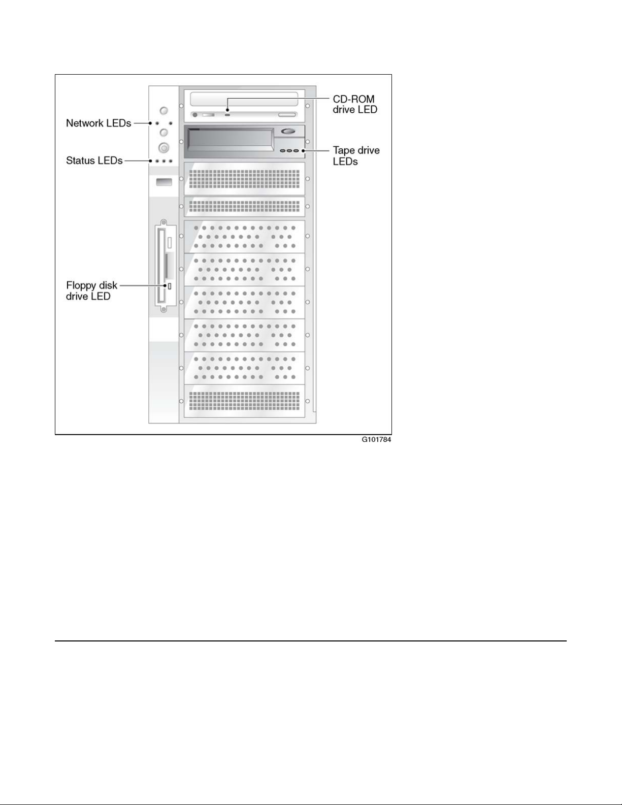
Network LED states
Figure 1: LED locations
The server LEDs, from top to bottom and left to right, indicate the status of the following:
• the ELAN and CLAN network interfaces
• hard drive
• power/sleep
• system
LEDs are also provided on the SCSI tape drive faceplate, floppy disk drive faceplate, and the
IDE CD-ROM drive faceplate.
Network LED states
The network LEDs are green and are located as follows:
Avaya CallPilot® 703t Server Maintenance and Diagnostics December 2010 21
Page 22

Troubleshooting your Avaya CallPilot® system
LED position Controller name Controller type LAN type
Left NIC1 10/100Base-T ELAN
Right NIC2 10/100/1000Base-T CLAN
IF the network interface
LED is
off a valid hardware connection with the network has not been
established.
Ensure that the Ethernet cable is connected to both the Ethernet
connector on the server and the respective network hub. If the
cable is connected, ensure that the cable is serviceable.
on a valid hardware connection with the network has been
established.
Note:
Before the 703t server can receive or transmit data, you must
configure valid IP settings on the 703t server.
blinking rapidly activity is occurring on the network.
Note:
This does not mean that the 703t server is actually
transmitting or receiving packets.
THEN
Hard drive LED states
The hard drive LED (the first LED in the row of LEDs below the power button on the 703t server
front panel) is not used because the 703t server is actually equipped with two hard drives.
There are no LEDs on the hard drives.
If hard drive faults occur on the 703t server, you can investigate them by reviewing events in
the following:
• operating system Event Viewer (see
• Avaya CallPilot Event Browser (see
You can also view the status of each hard drive in the MegaRAID Client. For instructions on
accessing and using this utility, see RAID operations on page 125
Viewing event logs on page 36)
Event Browser on page 60)
22 Avaya CallPilot® 703t Server Maintenance and Diagnostics December 2010
Page 23
Power/sleep LED states
The power/sleep LED is the middle LED in the row of LEDs below the power button on the
703t server's front panel (see "Status LEDs" in the diagram on LED locations on page 20). The
LED is green.
Power/sleep LED states
IF the power/sleep status
LED is
green steady the server is powered on.
off not applicable the server is powered off.
Note:
The Avaya CallPilot operating system does not support sleep mode on the server.
System status LED
The system status LED is the right LED in the row of LEDs below the power button on the 703t
server's front panel (see "Status LEDs" in the diagram on LED locations on page 20).
Note:
If the status LED indicates a problem, you can learn more about the problem by using the
server's event log. For more information, see Viewing event logs on page 36.
IF the system status LED
is
AND THEN
AND THEN
green steady the server is operating normally.
blinking the server's processor or memory is
disabled.
amber steady
Avaya CallPilot® 703t Server Maintenance and Diagnostics December 2010 23
• a critical temperature or voltage fault has
occurred.
• the CPU is not installed or is not
functioning.
Page 24

Troubleshooting your Avaya CallPilot® system
IF the system status LED
is
Tape drive LED states
The 703t server is equipped with an SLR60 tape drive. Three LEDs are located on the drive's
front panel. They are referred to as left, center, and right in the following table:
Table 2: SLR60 LEDs
Left Ready
Green
Center Activity
Green
AND THEN
blinking
off a fatal error occurred during the power-on
Right -
Error
Amber
• a power fault has occurred.
• a fan is faulty.
• a non-critical temperature or voltage fault
has occurred.
status test (POST).
Description
On On On
Blinking Off Off
Off Off Off
On Off Off
On Blinking Off
Off Off On
On Off On
LED test (2 seconds at power on) is running.
• Power-up self-test is running.
• Diagnostic cartridge activity is running.
• Cartridge is not inserted
• Tape is not loaded
• Cartridge is not inserted
• Tape is loaded but is not moving
• Tape is loaded and moving
• Tape is loading or unloading
• Cartridge is ejecting
• Cleaning is required
• Cartridge/tape is not loaded
• Cleaning is required
• Tape is loaded but not moving
24 Avaya CallPilot® 703t Server Maintenance and Diagnostics December 2010
Page 25
CD-ROM drive LED states
Left Ready
Green
On Blinking On
Off Blinking On Cleaning is in progress
Off Off Blinking
Note:
If the LED states indicate an error, contact your Avaya technical support representative.
Center Activity
Green
Right -
Error
Amber
Description
• Cleaning is required
• Tape is loaded and moving
• Tape is loading or unloading
• Cartridge is ejecting
• Unrecoverable tape drive failure has occurred.
• Cartridge has failed
• Microcode download failure has occurred
CD-ROM drive LED states
The CD-ROM drive's status LED is located on the drive's front panel. Refer to the following
table when interpreting the CD-ROM drive's status:
IF the CD-ROM drive LED is THEN
off the CD-ROM drive is idle.
on the CD-ROM drive is being accessed.
Interpreting rear panel LEDs
This section describes LED states visible at the back of the 703t server.
MPB96 DS30 connection link LED states
Refer to Slot definition and numbering on page 176 for the slot position of the MPB96 boards in
your server.
Avaya CallPilot® 703t Server Maintenance and Diagnostics December 2010 25
Page 26

Troubleshooting your Avaya CallPilot® system
Figure 26: MPB96 board on page 142 shows the location of three green LEDs on the MPB96
card bracket.
When THEN
all three are On the cables are connected properly.
one or more are Off
Blue LED
The blue LED in the back of the 703t system is not used in CallPilot.
It comes on for only a moment during a server reboot.
• there is no connection to the switch.
• the connection to the switch is intermittent.
• the DS30 clock signal coming from the MGate card
(NTRB18CA) is not working correctly.
You should:
• check each of the three individual branches of the
DS30 cable for faults, or replace the cable.
• check for a faulty MGate card (NTRB18CA) in the
switch.
Interpreting internal LEDs
This section describes LED states visible inside of the 703t server cabinet.
MPB96 LED states
There are three LEDs on the top of the MPB96 board. They are visible even from outside the
server cabinet, through the rear grill.
26 Avaya CallPilot® 703t Server Maintenance and Diagnostics December 2010
Page 27

PCI FPGA Done LED (closest to the I/O card bracket)
PCI FPGA Done LED (closest to the I/O card bracket)
This LED should go ON at power up and then OFF right away. This LED activity indicates that
the board is working properly and was correctly detected by the system.
If the LED stays ON after power up, the card is faulty, and you must replace the board.
DSP FPGA Done LED
This LED comes on at power up and stays ON until the CallPilot drivers are loaded just before
the diagnostic screen starts.
If this LED stays ON after the system has booted in the operating system and the CallPilot
diagnostic screen has started, either the board is faulty or there is a problem with the CallPilot
DSP and Windows Bus drivers.
CTbus FPGA Done LED (furthest from the I/O card bracket)
This LED works in tandem with the "DSP FPGA Done" LED, and should go on and off at the
same times.
RAID controller LED states
Refer to
your server.
There is one red LED and a row of eight small LEDs at the back of the RAID board.
Slot definition and numbering on page 176 for the slot position of the RAID boards in
To check if RAID board is working properly
1. The red LED comes on briefly at power up, then goes off. This indicates that the
card was accessed for detection successfully.
Avaya CallPilot® 703t Server Maintenance and Diagnostics December 2010 27
Page 28
Troubleshooting your Avaya CallPilot® system
At the same time, all eight LEDs at the back will light.
2. Four of the eight LEDs will then go off and stay that way.
There are four LEDs lit when the RAID card is working properly.
If all eight LEDs stay on after power up and boot, the card was not detected or is faulty.
Interpreting POST diagnostics
The Power-On-Self-Test (POST) is a system diagnostic program (stored in the BIOS) that runs
each time the 703t server is started. The function of POST is to test system components and
then to display status messages.
POST reports on the system status using POST beep codes. If an error occurs before video
initialization, POST emits beep codes that indicate errors in hardware, software, or firmware.
A beep code is a series of separate tones, each equal in length. Record the beep codes that
you hear before calling your Avaya customer support representative.
Important:
Some POST beep codes are critical and require you to replace your motherboard. Refer to
the tables in this section for more information about beep codes.
Types of beep codes
There are three types of beep codes on the 703t server:
• BIOS recovery beep codes (during a BIOS recovery procedure)
• bootblock error beep codes (for normal operation)
• bootblock error 3-beep codes (for normal operation)
Table 3: BIOS recovery beep codes
Beeps Error message Description
1 Recovery started Recovery process started.
2 Recovery boot error Unable to boot from floppy disk drive or CD-
Series of lowpitched single
beeps
Recovery failed Unable to process valid BIOS recovery
ROM drive. Recovery process will retry.
images. BIOS has already passed control to
the operating system and flash utility.
28 Avaya CallPilot® 703t Server Maintenance and Diagnostics December 2010
Page 29

Beeps Error message Description
Types of beep codes
2 long highpitched beeps
3 Recovery failed Recovery failed. Disk is not bootable or the
Recovery complete BIOS recovery succeeded. Ready for power-
down or restart.
disk is not inserted.
Table 4: Bootblock error beep codes
Number of
beeps
1 Refresh Timer Failure The memory refresh circuitry on the
2 Parity Error Parity cannot be reset.
3 Boot Block Failure See Table 5: Bootblock error 3-beep
4 System Timer System timer not operational.
5 Processor Failure Processor is faulty.
6 Keyboard Gate A20
7 Processor Exception Int
Error message Error message and conditions
motherboard is faulty.
codes on page 29.
Keyboard may be bad.
Failure
Processor generated an exception interrupt.
error
8 Display Memory Read/
Write Error
9 ROM checksum error BIOS checksum error has occurred.
10 Shutdown register error Shutdown register read/write error has
11 Invalid BIOS General BIOS error has occurred.
Video adapter is missing or faulty. This is not
a fatal error.
occurred.
Table 5: Bootblock error 3-beep codes
Number of
beeps
3 00h No memory was found in the system.
3 01h Memory of mixed types was detected.
3 02h EDO is not supported.
3 03h First row memory test has failed.
3 04h Mismatched DIMMs are in a row.
3 05h Base memory test failed
POST code Expansion card/controller
Avaya CallPilot® 703t Server Maintenance and Diagnostics December 2010 29
Page 30

Troubleshooting your Avaya CallPilot® system
Number of
beeps
3 06h Decompressing post module failed.
3 07-0Dh Generic memory error has occurred.
3 0Eh SMBus protocol error has occurred.
3 0Fh Generic memory error has occurred.
3 DDh CPU microcode cannot be found for
3 EEh CPU microcode cannot be found for
POST code Expansion card/controller
SCSI controller diagnostics
BIOS initialization
processor in slot 0.
processor in slot 1.
Most information about SCSI is displayed as part of the BIOS initialization screen.
During BIOS initialization, check to make sure that the tape drive is listed correctly. If the tape
drive is not listed correctly:
• Ensure that internal cable connections are made properly.
• Check that tape drive settings are correct.
• Check tape drive termination.
For more information refer to:
•
SCSI and IDE drive cabling on page 105
• Replacing the tape drive on page 113
RAID controller diagnostics
Most diagnostic information about RAID is available through beep warnings and status LEDs
when the server is rebooting.
30 Avaya CallPilot® 703t Server Maintenance and Diagnostics December 2010
Page 31

What to do when the server fails to boot into service
For more information refer to:
• Hard drive LED states on page 22
• RAID controller LED states on page 27
When the 703t server does not boot and makes audible beeps on page 32
•
• When the 703t server boots to the operating system and makes audible beeps on
page 33
What to do when the server fails to boot into service
The following sections suggest tasks you can perform to determine why the 703t server fails
the bootup cycle.
To investigate server boot problems
1. Ensure that you accurately record any diagnostic codes and error messages that
occur.
2. Try restarting the server by pressing the power button on the server.
3. During the boot sequence, view the diagnostic codes on the monitor for failures.
Note:
Allow 5 minutes for the boot cycle to complete.
4. If errors indicate a hardware problem with a failure to boot to the operating system or
if the server boots to the operating system, but fails to boot into CallPilot, refer to
the CallPilot Troubleshooting Guide
5. If you still cannot find the cause of the boot failure after performing the tasks
described in the following sections, call your Avaya technical support
representative.
When the 703t server does not boot and there are no audible beeps
To check why server fans are not turning when server does not boot
1. Ensure that the power cord is properly connected into an electrical outlet.
2. If the problem continues, ensure that there is power to the electrical outlet.
Avaya CallPilot® 703t Server Maintenance and Diagnostics December 2010 31
Page 32

Troubleshooting your Avaya CallPilot® system
To check why server does not boot with fans turning
1. Ensure that the monitor is turned on.
2. If the problem continues, ensure that the internal power supply to the boards is
connected correctly.
When the 703t server does not boot and the system board LED is red
If the right-most status LED on the front of the 703t server is red, this is usually due to failure
of the Board Management Controller.
The most likely cause is changing boards without completely powering down the 703t server
and disconnecting the power cable.
To check why server does not boot and system board LED is red
1. Shut down the 703t server
2. Disconnect the power cable.
3. Wait 1 minute.
4. Reconnect the power cable and attempt to restart the 703t server.
5. If the problem continues, contact your Avaya technical support representative for
assistance.
When the 703t server does not boot and makes audible beeps
If beeps are short
If the beeps are short in length, they are from the system board.
Typically, you will not see any video displayed on the monitor, and the right-most status LED
on the front of the 703t server will show a blinking or steady amber.
32 Avaya CallPilot® 703t Server Maintenance and Diagnostics December 2010
Page 33

To check why server does not boot and makes beeps
1. Make a note of the number of beeps and any error messages or POST codes.
2. Refer to Table 4: Bootblock error beep codes on page 29 and Table 5: Bootblock
error 3-beep codes on page 29, and use the collected information to identify the
cause of the failure.
3. Replace any component that is indicated as faulty.
If beeps are long
If the beeps are a series of high-pitched, long beeps, they are from the RAID system.
Typically, you will see messages displayed on the monitor indicating that the system is in a
critical state.
1. Ensure that internal hard drive cables are properly connected.
2. If the problem continues, RAID BIOS may be corrupted.
If beeps are long
3. If the problem continues, the drive is faulty. Replace the hard drive as described in
Replacing a faulty hard drive on page 106.
When the 703t server boots to the operating system and makes audible beeps
If the 703t server boots to the operating system but still makes audible beeps, one of the hard
drives is in critical condition.
To check if server has a hard drive in critical condition
Rebuild the hard drive as soon as the operating system has finished loading. Refer to
RAID splitting on page 132.
When the 703t server boots to the operating system but does not boot to CallPilot
If the 703t server does not boot to CallPilot, it may be due to the failure of a multimedia board.
Avaya CallPilot® 703t Server Maintenance and Diagnostics December 2010 33
Page 34

Troubleshooting your Avaya CallPilot® system
To check if multimedia board has failed
1. Check the diagnostic screen that is displayed immediately after you reboot the
system, and view the event logs. For instructions, see Viewing event logs on
page 36.
2. If the diagnostic or event log information indicates failure of a multimedia board,
replace the card as described in
3. If the diagnostic or event log information does not indicate failure of a multimedia
board, a software failure is the likely cause.
Refer to the Software Administration and Maintenance Guide (NN44200-600) for
instructions on how to reinstall software.
Replacing MPB96 boards on page 142.
34 Avaya CallPilot® 703t Server Maintenance and Diagnostics December 2010
Page 35

Chapter 4: Using Windows online
diagnostic tools
In this chapter
Overview on page 35
Viewing event logs on page 36
Using TCP/IP diagnostic tools on page 39
Using the chkdsk utility on page 47
Overview
This section describes how to access the runtime online diagnostic tools provided by the
Windows server software. Use these tools when a serious problem prevents the use of the
Avaya CallPilot® diagnostic tools that are available in CallPilot Manager.
Caution:
Risk of software corruption
Do not run any utilities that are not documented in this guide.
Operating system Event Viewer
The operating system Event Viewer provides event logs to help you diagnose and debug
system problems.
Avaya CallPilot® 703t Server Maintenance and Diagnostics December 2010 35
Page 36

Using Windows online diagnostic tools
TCP/IP diagnostics
The following TCP/IP diagnostic tools are described in this chapter:
• ipconfig on The ipconfig command on page 40
• ping on The ping command on page 41
• tracert on The tracert command on page 42
• arp on
• nbtstat on The nbtstat command on page 45
• netstat on The netstat command on page 46
These utilities help you to verify network connectivity. They help you to thoroughly test the
network interface and isolate any configuration problems. Network connectivity is essential to
CallPilot operation.
The arp command on page 43
chkdsk utility
The chkdsk utility checks a specified disk on the server and displays a status report. It is an
online utility, but it reduces system performance while it is running.
Viewing event logs
When the server startup cycle is complete, and if the CallPilot server has been configured (refer
to the Installation and Configuration Task List (NN44200-306), messages in dialog boxes on
the monitor indicate that CallPilot is ready to accept calls.
If one or more messages appears on the monitor, the message may contain information about
an event, or a fault may have occurred. To determine what happened, you can use the
following:
• operating system Event Viewer on the 703t server
• CallPilot Event Browser or Alarm Monitor in CallPilot Manager
Note:
The Event Browser and Alarm Monitor include online Help for events, which may help you
to resolve the problem. If you cannot log on to the CallPilot system using a web browser due
to server problems, then use the Event Viewer.
36 Avaya CallPilot® 703t Server Maintenance and Diagnostics December 2010
Page 37

Types of event logs
Three types of event logs are available from the Event Viewer, as follows:
Log type Description
System Logs events by Windows components, including RRAS or other
Windows services.
Security Logs security events, such as logons, logoffs and illegal access.
This option is available only to users with Administrative access.
Applications Logs events by application, such as database file errors.
To use the operating system Event Viewer
Types of event logs
1. Click Start → Programs → Administrative Tools → Event Viewer.
Result: The Event Viewer window appears.
Figure 2: Event viewer window
2. To view a log, click the name of the log in the left frame of the window.
Avaya CallPilot® 703t Server Maintenance and Diagnostics December 2010 37
Page 38

Using Windows online diagnostic tools
Figure 3: Application Log.
Figure 4: System log.
Note:
The Security log available only to administrators is not shown.
3. Look for error codes flagged with either of the following icons that have occurred
since the last startup.
38 Avaya CallPilot® 703t Server Maintenance and Diagnostics December 2010
Page 39

Using TCP/IP diagnostic tools
Note:
Each error is date and time stamped.
Indicates major or critical errors
Indicates minor errors
Indicates information
4. To determine the cause of the error, select and then double-click the error.
Result: A description of the error appears in an Event detail dialog box. Use the
description to help determine how to resolve errors.
Note:
If the error persists or does not suggest a solution, contact your Avaya support
representative.
5. Click OK.
Result: The event log reappears.
6. Click File → Exit.
Result: The Event Viewer closes.
Using TCP/IP diagnostic tools
This section describes the following TCP/IP diagnostic tools available for the network adapter:
• ipconfig
• ping
• tracert
• arp
• nbtstat
• netstat
These utilities help you to verify network connectivity, test the network interface, and isolate
configuration problems.
Avaya CallPilot® 703t Server Maintenance and Diagnostics December 2010 39
Page 40

Using Windows online diagnostic tools
The ipconfig command
The ipconfig command displays IP configuration information.
Ipconfig default
If you run the command without flags, it displays the IP address, subnet mask, and default
gateway for each adapter bound to TCP/IP.
Ipconfig command syntax
ipconfig /[ ]
The following flags are available for the ipconfig command:
Flag Description
/? Displays Help information.
/all Displays full configuration information.
/release Releases the IP address for the specified adapter.
/renew Renews the IP address for the specified adapter.
To run the ipconfig command from Windows
1. Click Start → Programs → Accessories → Command Prompt.
Result: The Command Prompt window appears.
2. At the Command prompt, type ipconfig <with appropriate parameters>.
Example: ipconfig /all
3. Press Enter.
Result: The system runs the ipconfig utility.
4. Type Exit to exit the Command Prompt window and return to Windows.
40 Avaya CallPilot® 703t Server Maintenance and Diagnostics December 2010
Page 41

The ping command
The ping command sends an echo request to a specified host. Use this command to verify
network connectivity to the remote device.
Ping command syntax
The ping command uses the following syntax:
ping [-t] [-a] [-n count] [-l size] [-f] [-i TTL] [-v TOS] [-r count]
[-s count] [[-j host-list] | [-k host-list]] [-w timeout]
destination-list
Table 6: Ping command parameters
The ping command
Parameter Description
-t Pings the specified host until interrupted.
-a Resolves addresses to host names.
-n count Specifies the number of echo requests to send.
-l size Sends buffer size.
-f Sets Don't Fragment flag in packet.
-i TTL Sets Time-To-Live
-v TOS Sets Type Of Service
-r count Records route for count hops
-s count Shows time stamp for count hops
-j host-list Shows loose source route along host list
-k host-list Shows strict source route along host list
-w timeout Sets time-out in milliseconds to wait for each reply
To run the ping command from Windows
1. Click Start → Programs → Accessories → Command Prompt.
Avaya CallPilot® 703t Server Maintenance and Diagnostics December 2010 41
Page 42

Using Windows online diagnostic tools
Result: The Command Prompt window appears.
2. At the Command prompt, type ping <destination IP address> (for example, ping
200.286.32.0), or ping <computer name>.
3. Press Enter.
Result: The system displays the ping results.
4. Type Exit to exit the Command Prompt window and return to Windows.
The tracert command
This utility determines the route taken to a destination.
How tracert works
The tracert utility follows several steps to complete its task:
• Tracert sends Internet Control Message Protocol (ICMP) echo packets with varying TimeTo-Live (TTL) values to the destination.
• Each router along the path must decrement the TTL on a packet by at least one before
forwarding it, so the TTL is effectively a hop count.
• When the TTL on a packet reaches zero, the router sends back an ICMP Time Exceeded
message to the source system.
• Tracert determines the route by sending the first echo packet with a TTL of one, and
incrementing the TTL by one on each subsequent transmission until the target responds,
or the maximum TTL is reached.
• Tracert then examines the ICMP Time Exceeded messages sent back by intermediate
routers.
Tracert syntax
The tracert command uses the following syntax:
tracert [-d] [-h maximum_hops] [-j host_list] [-w timeout]
target_name
42 Avaya CallPilot® 703t Server Maintenance and Diagnostics December 2010
Page 43

To run the tracert command from Windows
Table 7: Tracert parameters
Parameter Description
-d Specifies not to resolve addresses to hostnames.
-h maximum_hops Specifies the maximum number of hops to search for the target.
-j host-list Specifies a loose source route along the host list.
-w timeout Waits the number of milliseconds specified by the time-out for
each reply.
target_name Shows the name of the target host.
To run the tracert command from Windows
1. Click Start → Programs → Accessories → Command Prompt.
Result: The Command Prompt window appears.
2. At the Command prompt, type the following command:
tracert [-d] [-h maximum_hops] [-j host_list] [-w timeout]
[target_name]
Example: tracert 200.286.0.32
3. Press Enter.
Result: The system runs the tracert utility.
4. Type Exit to exit the Command Prompt window and return to Windows.
The arp command
The arp command displays and modifies the IP-to-physical address translation tables used by
Address Resolution Protocol (arp).
Arp command syntax
The arp command uses the following syntax:
arp -s inet_addr eth_addr [if_addr]
Avaya CallPilot® 703t Server Maintenance and Diagnostics December 2010 43
Page 44

Using Windows online diagnostic tools
arp -d inet_addr [if_addr]
arp -a [inet_addr] [-N if_addr]
Table 8: Arp parameters
Parameter Description
-a Displays current arp entries by interrogating the current protocol
-g Same as -a.
inet_addr Specifies an Internet address.
if_addr Specifies the Internet address of the interface whose address
eth_addr Specifies a physical address.
-N if_addr Displays the arp entries for the network interface specified by
data. If inet_addr is specified, the IP and physical addresses for
only the specified computer appear. If more than one network
interface uses arp, entries for each arp table appear.
translation table should be modified. If not present, the first
applicable interface is used.
if_addr.
-d Deletes the host specified by inet_addr.
-s Adds the host and associates the Internet address inet_addr
with the Physical address eth_addr. The physical address is
given as six hexadecimal bytes separated by hyphens. The
entry is permanent.
To run the arp command from Windows
1. Click Start → Programs → Accessories → Command Prompt.
Result: The Command Prompt window appears.
2. At the Command prompt, type arp with the required parameters (for example, arp
-g 200.286.0.32).
3. Press Enter.
Result: The system runs the arp command.
Type Exit to exit the Command Prompt window and return to Windows.
44 Avaya CallPilot® 703t Server Maintenance and Diagnostics December 2010
Page 45

The nbtstat command
The nbtstat command displays protocol statistics and current TCP/IP connections using NBT.
Nbtstat command syntax
The nbtstat command uses the following syntax:
nbtstat [-a remotename] [-A IP address] [-c] [-n] [-R] [-r] [-S] [-s]
[interval]
Table 9: Nbstat parameters
Parameter Description
The nbtstat command
-a remotename Lists the remote computer's name table using its name.
-A IP address Lists the remote computer's name table using its IP address.
-c Lists the contents of the NetBIOS name cache giving the IP
address of each name.
-n Lists local NetBIOS names. Registered indicates that the name
is registered by broadcast (Bnode) or WINS (other node types).
-R Reloads the LMHOSTS file after purging all names from the
NetBIOS name cache.
-r Lists name resolution statistics for Windows networking name
resolution. On a Windows computer configured to use WINS,
this option returns the number of names resolved and registered
through broadcast or through WINS.
-S Displays both client and server sessions, listing the remote
hosts by IP address only.
-s Displays both client and server sessions, and attempts to
convert the remote host IP address to a name using the HOSTS
file.
interval Displays selected statistics, pausing interval seconds between
each display. Press Ctrl+C to stop displaying statistics. Without
this parameter, nbtstat prints the current configuration
information once.
Avaya CallPilot® 703t Server Maintenance and Diagnostics December 2010 45
Page 46

Using Windows online diagnostic tools
To run the nbtstat command from Windows
1. Click Start → Programs → Accessories → Command Prompt.
Result: The Command Prompt window appears.
2. At the Command prompt, type nbtstat with the required parameters.
3. Press Enter.
Result: The system runs the nbtstat utility.
Type Exit to exit the Command Prompt window and return to Windows.
The netstat command
The netstat command displays current TCP/IP network connections and protocol statistics.
Netstat command syntax
The netstat command uses the following syntax:
netstat [-a] [-e] [-n] [-s] [-p proto] [-r] [interval]
Table 10: Netstat parameters
Parameter Description
-a Displays all connections and listening ports.
-e Displays Ethernet statistics. This can be combined with the -s
option.
-n Displays addresses and port numbers in numerical form.
-s Displays per-protocol statistics.
-p proto Shows connections for the protocol specified by proto. Proto
can be tcp or udp. If used with the -s option, proto can be tcp,
udp, or ip.
-r Displays the contents of the routing table.
interval Redisplays selected statistics, pausing between each display.
Press Ctrl+C to stop redisplaying.
46 Avaya CallPilot® 703t Server Maintenance and Diagnostics December 2010
Page 47

To run the netstat command from Windows
To run the netstat command from Windows
1. Click Start → Programs → Accessories → Command Prompt.
Result: The Command Prompt window appears.
2. At the Command prompt, type netstat with the required parameters.
3. Press Enter.
Result: The system runs the netstat utility.
4. Type Exit to exit the Command Prompt window and return to Windows.
Using the chkdsk utility
The chkdsk utility checks a specified disk on the server and displays a status report. It can be
run on drives C, D, E, or F. It is an online utility, but it reduces system performance while it is
running.
The chkdsk utility checks for problems at the Windows file system level. Any problems existing
at this level can cause problems for CallPilot. Even if there are no problems at the Windows
file system level, CallPilot can still be affected by problems at the CallPilot file system level.
Note:
A version of this utility, called autocheck, automatically runs during Windows startup. Output
from this utility appears on the blue startup screen.
Chkdsk utility syntax
The chkdsk utility uses the following syntax:
chkdsk [drive:][path]filename] [/F] [/V] [/R]
Table 11: Chkdsk parameters
Parameter Description
drive: Enter the drive letter of the drive that you want to check.
filename Enter the names of files to check for fragmentation.
Avaya CallPilot® 703t Server Maintenance and Diagnostics December 2010 47
Page 48

Using Windows online diagnostic tools
Parameter Description
/F Add this parameter to fix errors on the disk.
/V Add this parameter to display the full pathname of every file on
the disk.
/R Add this parameter to locate bad sectors and to recover
readable information.
To run the chkdsk utility from Windows
1. Click Start → Programs → Accessories → Command Prompt.
Result: The Command Prompt window appears.
2. At the Command prompt, type chkdsk <drive letter:> (for example, chkdsk c:).
3. Press Enter.
Result: The system runs the chkdsk utility.
4. Type Exit to exit the Command Prompt window and return to Windows.
48 Avaya CallPilot® 703t Server Maintenance and Diagnostics December 2010
Page 49

Chapter 5: Using serial port diagnostic tools
In this chapter
Overview on page 49
Shutting down services on page 49
Conducting TSTSERIO tests on page 51
Conducting TSTSERIO tests with the loopback plug on page 53
Restarting services on page 54
Overview
You may want to test the serial ports when remote access does not work.
This chapter describes how to run serial port diagnostics on the Avaya CallPilot® server using
the TSTSERIO command. Direct the TSTSERIO command to serial ports on the server after
services on these ports have been shut down manually, as described in this chapter.
Shutting down services
This section describes how to shut down a service using a specific serial port. Use the following
procedures before invoking the TSTSERIO local loopback tests.
Caution:
Risk of communications loss
By stopping the services on COM 1 or COM 2, you lose the support access feature.
Caution:
Risk of stopping call processing
Avaya CallPilot® 703t Server Maintenance and Diagnostics December 2010 49
Page 50

Using serial port diagnostic tools
By stopping the services on COM 2, you stop call processing on Avaya CallPilot.
Service to stop for COM 1 testing
Services to stop for COM 2 testing
• CallPilot SLEE Service
• CallPilot MWI Service
• CallPilot Access Protocol Emulator
• CallPilot Blue Call Router
• CallPilot Call Channel Router
• CallPilot Time Service
• Routing and Remote Access
Net Stop command
Use the Net Stop command to stop a specified service on a serial port.
Net Stop command syntax
The Net Stop command uses the following syntax:
net stop "service_name"
Important:
You must restart the services that you shut down through the Net Start command after
running the diagnostic. For details, see Restarting services on page 54.
50 Avaya CallPilot® 703t Server Maintenance and Diagnostics December 2010
Page 51

To invoke the Net Stop command from Windows
To invoke the Net Stop command from Windows
1. Click Start → Programs → Accessories → Command Prompt.
Result: The Command Prompt window appears.
2. At the Command prompt, type net stop "service_name", and then press Enter.
Note:
The quotation marks are required, as in the example above.
Result: The system runs the Net Stop command utility.
3. Type Exit, and then press Enter to exit the Command Prompt window.
Conducting TSTSERIO tests
The TSTSERIO command performs local loopback tests of the serial communication ports
from the server runtime environment.
Note:
Before conducting these tests, shut down the appropriate services. See Shutting down
services on page 49.
Caution:
Risk of communications loss
By stopping the services on COM 1 or COM 2, you lose the support access feature.
Caution:
Risk of stopping call processing
By stopping the services on COM 2, you stop call processing on CallPilot.
TSTSERIO command syntax
The syntax for the TSTSERIO command is as follows:
TSTSERIO [/?] /P:comport [/S:subtstname] [/L:loops]
Avaya CallPilot® 703t Server Maintenance and Diagnostics December 2010 51
Page 52

Using serial port diagnostic tools
Flag Requirement Description
? n/a Displays Help.
/P:comport Required Specifies the symbolic port name assigned to the port
you want to test.
/S:subtstname Optional Specifies a TSTSERIO subtest. See the table below
for a description of the available subtests.
/L:loops Optional Specifies the number of times (up to a maximum of 65
535) to execute the requested test. The default
number of tests is 1. A value of 0 infinitely loops until
you enter Ctrl+C.
TSTSERIO internal loopback diagnostic subtests
The following internal loopback subtests are available for the TSTSERIO command. For each
of these tests, the communications resource must be available:
Subtest name Description
idat Internal data bus loopback
imsr Internal modem status register
baud Internal data bus loopback at various baud rates
word Test 5-, 6-, 7-, and 8-bit data lengths
stop Test 1, 1.5, and 2 stop bits
pari Test odd/even parity
fifo Test that device can operate in fifo mode
To invoke the TSTSERIO /P command from Windows
1. Click Start → Programs → Accessories → Command Prompt.
Result: The Command Prompt window appears.
2. At the Command prompt, type tstserio with the required parameters, and then press
Enter.
52 Avaya CallPilot® 703t Server Maintenance and Diagnostics December 2010
Page 53

TSTSERIO external loopback plug subtests
For example, type TSTSERIO /P com1 or TSTSERIO /P com 2, and then press
Enter.
3. Type Exit, and then press Enter to exit the Command Prompt window.
TSTSERIO external loopback plug subtests
The following external loopback subtests are available for the TSTSERIO command. For each
of these tests, an external loopback connector must be used. For more information, see
Conducting TSTSERIO tests with the loopback plug on page 53.
Subtest name Description
edat External data bus loopback. This test requires an external
loopback connector.
emsr External modem status register. This test requires an external
loopback connector.
eint Test ability of device to generate interrupts. This test requires
an external loopback connector.
To invoke the TSTSERIO /S command from Windows
1. Click Start → Programs → Accessories → Command Prompt.
Result: The Command Prompt window appears.
2. At the Command prompt, type tstserio with the required parameters, and then press
Enter.
For example, type TSTSERIO /P com1 /S extr, and then press Enter.
3. Type Exit, and then press Enter to exit the Command Prompt window.
Conducting TSTSERIO tests with the loopback plug
The TSTSERIO command requires an external loopback connector plug for its edata, emsr,
and eint subtests.
Avaya CallPilot® 703t Server Maintenance and Diagnostics December 2010 53
Page 54

Using serial port diagnostic tools
9-pin connector plug
The standard serial loopback connector is a female 9-pin D-sub connector. This connector has
the following pins wired together:
• CTS (pin 8) wired to (pin 7) RTS
• SIN (pin 2) wired to (pin 3) SOUT
• DTR (pin 4) wired to (pin 6) DSR
Once the plug is installed on the serial port, TSTSERIO can be invoked according to the To
invoke the TSTSERIO /P command from Windows on page 52.
Restarting services
This section describes how to restart the services for COM 1 or COM 2 after invoking the
TSTSERIO local loopback tests.
Service to restart after COM 1 testing
Services to restart after COM 2 testing
• CallPilot SLEE Service
• CallPilot MWI Service
• CallPilot Access Protocol Emulator
• CallPilot Blue Call Router
• CallPilot Call Channel Router
• CallPilot Time Service
• Routing and Remote Access
54 Avaya CallPilot® 703t Server Maintenance and Diagnostics December 2010
Page 55

Net Start command
Use the Net Start command to restart a specified service on a serial port. The syntax for the
Net Start command is as follows:
net start "[service-name]"
To invoke the Net Start command from Windows
1. Click Start → Programs → Accessories → Command Prompt.
Result: The Command Prompt window appears.
2. At the Command prompt, type net start "service_name", and then press Enter.
Net Start command
Note:
The quotation marks are required, as in the example above.
3. Type Exit, and then press Enter to exit the Command Prompt window.
Avaya CallPilot® 703t Server Maintenance and Diagnostics December 2010 55
Page 56

Using serial port diagnostic tools
56 Avaya CallPilot® 703t Server Maintenance and Diagnostics December 2010
Page 57

Chapter 6: Using CallPilot Manager to
monitor hardware
In this chapter
Understanding fault management on page 57
Alarm Monitor on page 59
Event Browser on page 60
Channel and Multimedia Monitors on page 61
The Maintenance page on page 62
Viewing component states on page 64
Starting and stopping components on page 66
Running integrated diagnostics on page 68
Viewing the last diagnostic results on page 71
Working with the Multimedia Monitor on page 72
Working with the Channel Monitor on page 73
Understanding fault management
Fault management is a term that describes how the Avaya CallPilot® server detects and notifies
you of potential or real hardware problems (faults). The server processes events to detect
hardware problems and raises alarms to notify you when these problems occur.
Avaya CallPilot® 703t Server Maintenance and Diagnostics December 2010 57
Page 58

Using CallPilot Manager to monitor hardware
Event processing
An event is any change in system configuration or operational state. An event is also any action
taken by the system that requires user notification. Events can be as insignificant as a user
logon attempt or as serious as a faulty MPB switching to disabled status.
All events are reported to the fault management server, a subsystem within the CallPilot server.
The fault management server enables the server to listen and respond to its clients. The
interaction is called event processing and is the means by which the server detects hardware
faults.
Alarm notification
Alarms are warnings generated by events. Alarms communicate the same information as
events. However, alarms are reported in the Alarm Monitor instead of the Event Browser, and
are managed differently than events.
When an alarm appears in the Alarm Monitor, you must investigate the problem, isolate it, and
then fix the cause of the problem. When you fix the problem, ensure that the alarm is cleared
from the Alarm Monitor.
Note:
You may be required to clear the alarm manually.
Component dependencies
The status of some components is dependent on the operational status of other components. If
a component fails or is stopped, the dependent components go out of service.
Note:
Based on the CallPilot server type, and the type of switch connected to CallPilot, some of
these components may not appear on your system.
Component Dependent components
Media Bus All MPBs and all multimedia and call channels.
MPB board All multimedia and call channels associated with the MPB board.
58 Avaya CallPilot® 703t Server Maintenance and Diagnostics December 2010
Page 59

Component Dependent components
Time Switch All multimedia and call channels associated with the same MPB as
the time switch.
DS30X All DS30X channels associated with the DS30X link.
Detecting hardware problems
Typically, you first become aware of a hardware problem when an alarm is raised. All hardware
faults produce an alarm (or series of alarms, depending on the problem) in the Alarm Monitor.
Other indications of a hardware problem include the following:
• user complaints
• call processing difficulties, such as busy signals, static, dropped calls, connection
problems, and cross talk (hearing other conversations)
• system administrator logon difficulties
Detecting hardware problems
• alert icons on the Maintenance screen
Alarm Monitor
Use the Alarm Monitor to investigate one or more raised alarms.
About alarms
Alarms are warnings generated by events. Alarms communicate the same information as
events. However, alarms are reported in the Alarm Monitor instead of the Event Browser, and
are managed differently than events:
• Alarms appear in the Alarm Monitor only for Minor, Major, and Critical events (not
Information events). All events can be reported in the Event Browser (depending on
filtering criteria defined in the Event Browser).
• The first time an event occurs, it generates an alarm that appears in the Alarm Monitor.
If the same event continues to occur, a new alarm is not generated. Instead, the time and
date assigned to the original generated alarm is updated.
• Alarms can be cleared from the Alarm Monitor, but the event that generated the alarm is
not cleared from the event log or the Event Browser.
Avaya CallPilot® 703t Server Maintenance and Diagnostics December 2010 59
Page 60

Using CallPilot Manager to monitor hardware
Each alarm in the Alarm Monitor has Help text that often provides a solution to the problem. If
the solution is not apparent, use the Event Browser or the Maintenance screen to further
investigate the problem.
To investigate using the Alarm Monitor
1. Run CallPilot Manager and log in.
2. In CallPilot Manager, click System → Alarm Monitor.
Result: The Alarm Monitor window appears.
3. Click the Event Code for the first critical or major alarm.
Result: A description of the event appears in a new web browser window.
4. Review the description and recovery action.
5. Repeat steps
6. If the solution to the problem is not apparent, obtain the return code of the first event
and continue the investigation by using the Event Browser (see Event Browser on
page 60).
Note:
For information on how to use the Alarm Monitor, refer to the Administrator's Guide
(NN44200-601), or the CallPilot Manager online Help.
Event Browser
Use the Event Browser to investigate a series of events that occurred around the time an alarm
was raised. The event listing can help you determine the root cause of a problem.
About events
3 on page 60 and 4 on page 60 for a more alarms, if necessary.
The Event Browser displays events that have been recorded in the server log. Each event
identifies the time the event occurred, the object that generated the event, and the cause of
the event.
Events are classified as Information, Minor, Major, or Critical. By default, the Event Browser
displays only the latest 100 critical events.
60 Avaya CallPilot® 703t Server Maintenance and Diagnostics December 2010
Page 61

Note:
Avaya recommends that you change the Event Browser filter criteria to display Minor and
Major events as well. Minor and Major events can indicate significant system problems.
To investigate using the Event Browser
1. Run CallPilot Manager and log in.
2. In CallPilot Manager, click System → Event Browser.
Result: The Event Browser window appears
3. Click an event that appears to be related to the problem, or an event that occurred
near the time the alarm was raised.
Result: A description of the event appears in a new web browser window.
4. View the description and recovery action.
To investigate using the Event Browser
5. Repeat steps
6. If the solution to the problem is not apparent, contact your Avaya technical support
representative.
Note:
For information on how to use the Event Browser, refer to the Administrator's Guide
(NN44200-601), or the CallPilot Manager online Help.
3 on page 61 and 4 on page 61 for more events, if necessary.
Channel and Multimedia Monitors
The Channel Monitor shows the status of call channels. The call channels are the connections
between the server and the switch that carry the call signals to CallPilot.
The Multimedia Monitor shows the status of multimedia channels. The multimedia channels
are the DSP ports that process the calls. They are the voice, fax, and speech recognition
channels.
Avaya CallPilot® 703t Server Maintenance and Diagnostics December 2010 61
Page 62

Using CallPilot Manager to monitor hardware
Disabling call channels
If you must take the CallPilot system out of service to perform software or hardware
maintenance, Avaya recommends that you disable all call channels first. There are two ways
to disable the call channels:
• Courtesy stop the channels (preferred method).
When you courtesy stop call channels, CallPilot waits until the channels are no longer
active before disabling them, instead of suddenly terminating active calls.
• Stop the channels.
When you stop channels, you suddenly disable them and terminate all active calls.
The Maintenance page
Use the Maintenance page in CallPilot Manager to do the following:
• Obtain general information about components.
• View component states.
• Start and stop components.
• Run integrated diagnostic tests.
• View the results of the last diagnostic test run against a component.
What the Maintenance page provides
The Maintenance page identifies the server platform and switch connectivity type. It also
provides a tree that, when expanded, lists the physical and logical hardware components down
the left side of the screen. To list the server hardware components, click the plus sign (+) at
the top of the tree. To list the subcomponents for each component, click the plus sign (+) beside
the component.
Note:
The components that are listed on the Maintenance page are based on the CallPilot server
type and the switch that is connected to CallPilot.
When you click a component, the page refreshes to show the details about that component.
62 Avaya CallPilot® 703t Server Maintenance and Diagnostics December 2010
Page 63

Maintenance activities for each component
Table 12: Maintenance page section details
Section Description
General This section shows general technical information about the selected
component. This typically includes the following details:
• the name, class, type, series, or version of a CallPilot server
• various capabilities of a component (for example, whether a
component is removable)
Note:
This section does not appear for all components.
Maintenance This section shows the state of the selected component. Use this
section to start and stop a component before running a diagnostic
test.
This section appears only for components on which you are allowed
to perform maintenance administration.
For more information about working with component states, see the
following sections:
• Viewing component states on page 64
• Starting and stopping components on page 66
Diagnostics Use the Diagnostics section to run one or more diagnostic tests, or
to view the results of the last diagnostic tests that were run on the
selected component.
This section appears only for components on which you are allowed
to run diagnostics. For more information about running diagnostics,
see the following sections:
• Running integrated diagnostics on page 68
• Viewing the last diagnostic results on page 71
Maintenance activities for each component
Table 13: Maintenance activities on page 63 identifies the maintenance activities you can
perform for each component listed in the component tree.
Table 13: Maintenance activities
Component Start, stop? Courtesy stop? Diagnostics
available?
Media Bus Yes No No No
MPB board Yes No Yes Yes
Avaya CallPilot® 703t Server Maintenance and Diagnostics December 2010 63
Replaceable ?
Page 64

Using CallPilot Manager to monitor hardware
Component Start, stop? Courtesy stop? Diagnostics
Time Switch No No No No
Multimedia
channels
Call channels Yes Yes No No
DS30X link Yes No No No
Note:
The MGate card and DS30X cable are replaceable. If you are having problems with the
DS30X link, determine if either one or both of those items are causing the problem and
need to be replaced.
Yes Yes No No
Viewing component states
View a component state to determine the general condition of the component, including
whether the component is disabled or off duty. The component state is shown in the
Maintenance section of the Maintenance screen.
Replaceable ?
available?
Component states
You can determine the state of a component by looking at the State box in the Maintenance
section.
State Description
Active The component is working and currently involved in processing
Disabled The diagnostic failed.
Idle The component is working but not currently involved in
InTest A diagnostic is running on the component.
Loading The component has been started, which takes it out of the Off
No resources The hardware required for the component to operate is not
a call.
processing a call.
Duty state.
This state occurs quickly and is immediately followed by Idle.
installed or is not operating properly.
64 Avaya CallPilot® 703t Server Maintenance and Diagnostics December 2010
Page 65

Not Configured The component is not configured in CallPilot.
Off Duty The component has been stopped.
Remote Off Duty The component has been taken out of service at the switch.
Shutting Down The component is in the process of stopping. This state occurs
Uninitialized The call processing component has not initialized the resource.
Alert icons
If one of the following icons appears next to a component in the tree, then the component or
one of its subcomponents is experiencing a problem:
Alert icons
State Description
For example, a multimedia channel is not being used because
it was not allocated in the Configuration Wizard.
quickly and is immediately followed by Off Duty.
Icon Description
A problem exists with a subcomponent of the selected component. Expand the
tree to locate the subcomponent with the problem.
A problem exists with the selected component.
To view the state of a hardware component
1. Run CallPilot Manager and login.
2. In CallPilot Manager, click Maintenance → Maintenance Admin.
Result: The Maintenance screen appears.
3. Click the plus sign (+) beside the CallPilot server to expand the component tree.
4. Continue clicking the plus sign (+) until the component with which you want to work is
visible.
5. Click the hardware component with which you want to work.
Result: The Maintenance screen refreshes to show details about the component.
6. Scroll down to the Maintenance section.
7. View the state of the selected component in the State box.
Avaya CallPilot® 703t Server Maintenance and Diagnostics December 2010 65
Page 66

Using CallPilot Manager to monitor hardware
Starting and stopping components
When you stop a component, you take it out of service and prevent it from operating. You must
stop a component before you can replace it (if the component is replaceable) or run a diagnostic
test on it.
To bring an out-of-service component back into service, you must start it.
Start and stop components from the Maintenance section on the Maintenance screen.
Important:
Avaya recommends that, if possible, you courtesy stop a component. Courtesy stop is
available only at the individual channel level.
To courtesy down CallPilot, use the following:
• Multimedia Monitor - to courtesy stop a range of multimedia channels
• Channel Monitor - to courtesy stop a range of call channels:
DS30X channels (also known as DS0 channels)
Stop versus Courtesy stop
The following two methods of taking a component out of service allow you to choose how active
calls are affected:
Courtesy stop
A Courtesy stop is the recommended way to take the component out of service only after the
component has finished processing an active call. Courtesy stop is preferred over a regular
Stop.
• If the component is processing a call, the call is not dropped; the component remains
active until the call is finished.
• If the component is not in use, it is taken out of service immediately.
66 Avaya CallPilot® 703t Server Maintenance and Diagnostics December 2010
Page 67

Stop
A Stop takes the component out of service immediately, regardless of whether the component
is currently processing calls. All active calls are dropped. Perform a Stop only when severe
problems affecting a large number of incoming calls occur or if your organization determines
a special need for it.
Components that can be started and stopped
The following components can be started and stopped when connected to a Meridian 1* or
Avaya Communication Server 1000* switch:
Note:
If you want to start or stop more than one or two multimedia or call (DS30X) channels, use the
Multimedia Monitor or Channel Monitor. For instructions, see
Monitors on page 61.
Channel and Multimedia
Stop
Component Effect of stopping
Media Bus Takes all call processing resources out of service.
MPB board Takes all call processing resources on the selected board out
of service.
Time Switch You cannot perform maintenance administration on the time
switch.
Multimedia Channel Takes the selected Multimedia Channels out of service.
DS30X link Takes the selected DS30X link and the channels that belong to
that link out of service.
Channels Takes the selected DS30X channel out of service.
To start or stop a component
1. Run CallPilot Manager and login.
2. In CallPilot Manager, click Maintenance → Maintenance Admin.
Result: The Maintenance screen appears.
Avaya CallPilot® 703t Server Maintenance and Diagnostics December 2010 67
Page 68

Using CallPilot Manager to monitor hardware
3. Click the plus sign (+) beside the CallPilot server to expand the component tree.
4. Continue clicking the plus sign (+) until the component with which you want to work is
visible.
5. Click the hardware component that you want to start or stop.
Result: The Maintenance screen refreshes to show details about the component.
6. Scroll down to the Maintenance section.
7. Click Courtesy Stop, Stop, or Start as required.
Button Description
Start If the selected component is out of service, click this button to put it into
service.
Courtesy Stop Click this button to take the selected component out of service. CallPilot
waits for the call to be completed before disabling the component.
Important:
If you are courtesy stopping all components (that is, you are taking the
entire system down), ensure that you inform all administrators,
desktop messaging users, and web messaging users so that they can
log off their sessions before you proceed.
The system asks you to confirm the Courtesy stop. If you click OK, the
component is put out of service after all calls are finished.
Stop Click this button to take the selected component out of service
immediately. All calls that are in progress are disconnected immediately.
Important:
If you are stopping all components (that is, you are taking the entire
system down), ensure that you inform all administrators, desktop
messaging users, and web messaging users so that they can log off
their sessions before you proceed.
Running integrated diagnostics
Run diagnostic tests from the Diagnostics section on the Maintenance screen in the following
circumstances:
• You want to ensure that a component is operating properly after installing or reinstalling it.
• The CallPilot server has trouble processing incoming calls, and you hope that diagnostic
results can tell you why.
Problems include static, dropped calls, and cross talk (hearing another conversation).
68 Avaya CallPilot® 703t Server Maintenance and Diagnostics December 2010
Page 69

Before you begin
Important:
Take the component out of service before you run the diagnostic test. See Starting and
stopping components on page 66.
Diagnostic tests available for each component
The diagnostic tests that are available for each component are listed in the Diagnostic section
of the Maintenance screen. To view the list of diagnostic tests for a particular component, click
the component in the component tree.
Before you begin
Components that have diagnostic tests available
The following table identifies the components on which you can run diagnostics when
connected to a Meridian 1 switch or Communication Server 1000.
Table 14: Diagnostics tests available for components
Component Diagnostics available? Replaceable?
Media Bus No No
MPB board Yes Yes
Time Switch No No
Multimedia Channels No Yes (via MPB96 board)
DS30X link No No
Channels No No
If a diagnostic test fails or cannot be run
If a warning message appears, the diagnostic test cannot be run because a prerequisite
condition has not been met. If a diagnostic test fails, a message appears in a new browser
window (see the example on page step 9 on page 70).
Avaya CallPilot® 703t Server Maintenance and Diagnostics December 2010 69
Page 70

Using CallPilot Manager to monitor hardware
In both cases, check the Alarm Monitor to determine the reason and the appropriate action to
take.
If the Alarm Monitor and Event Browser do not provide a solution to a hardware problem, you
may need to replace or service a component. If the problem is with a component that is not
replaceable because it is not a physical entity (such as the Time Switch), you must either
replace its parent component or contact your Avaya technical support representative,
depending on the component.
To run a diagnostic test
Important:
Avaya recommends that you courtesy stop rather than stop a component if possible. For
instructions, see Starting and stopping components on page 66.
1. Run CallPilot Manager and log in.
2. In CallPilot Manager, click Maintenance → Maintenance Admin.
Result: The Maintenance screen appears.
3. Click the plus sign (+) beside the CallPilot server to expand the component tree.
4. Continue clicking the plus sign (+) until the component with which you want to work is
visible.
5. Click the hardware component for which you want to run diagnostics.
Result: The Maintenance screen refreshes to show details about the component.
6. Scroll down to the Maintenance section, and ensure that the component is out of
service.
Note:
For instructions on taking the component out of service, see To start or stop a
component on page 67.
7. Scroll down to the Diagnostics section.
8. Check the check box for each diagnostic that you want to run.
Note:
If you want to run all of the diagnostics, check the Diagnostic Description check
box at the top of the list.
9. Click Run.
70 Avaya CallPilot® 703t Server Maintenance and Diagnostics December 2010
Page 71

Result: A new web browser window opens to display the progress and results of
the diagnostics. The Diagnostic Results box in the Diagnostics section displays
diagnostic results when you click Get Last Result.
Viewing the last diagnostic results
You can review the results of previously run diagnostics by clicking the Get Last Results button
for a component.
To view the last diagnostics result
Important:
Avaya recommends that you courtesy stop rather than stop a component if possible. For
instructions, see
Starting and stopping components on page 66.
Viewing the last diagnostic results
1. Run CallPilot Manager and log in.
2. In CallPilot Manager, click Maintenance → Maintenance Admin.
Result: The Maintenance screen appears.
3. Click the plus sign (+) beside the CallPilot server to expand the component tree.
4. Continue clicking the plus sign (+) until the component with which you want to work is
visible.
5. Click the hardware component for which you want to run diagnostics.
Result: The Maintenance screen refreshes to show details about the component.
6. Scroll down to the Diagnostics section.
7. Check the check box for each diagnostic for which you want to review results.
8. Click Get Last Result.
Result: The results appear in the Diagnostic Results box with the following
information:
• diagnostic title
• diagnostic result: pass or fail
• the date and time the test was completed
Avaya CallPilot® 703t Server Maintenance and Diagnostics December 2010 71
Page 72

Using CallPilot Manager to monitor hardware
Working with the Multimedia Monitor
The Multimedia Monitor shows the status of multimedia channels. The multimedia channels
are the DSP ports that process the calls. They are the voice, fax, and speech recognition
channels.
To view or work with multimedia channel states
1. Run CallPilot Manager and log in.
2. In CallPilot Manager, click Maintenance → Multimedia Monitor.
Result: The Multimedia Monitor screen appears, showing the channels associated
with each DSP
Note:
For an explanation of the channel states, refer to the CallPilot Manager online
Help.
3. Do one of the following:
IF you want to stop or start THEN
all of the channels associated with a
DSP
only one or several channels that are
associated with a DSP
4. Click Courtesy Stop, Stop, or Start as required.
Result: If you clicked Courtesy Stop or Stop, you are asked to confirm the Courtesy
Stop or Stop. Click OK.
The selected channels change to idle or on-duty status, according to the action you
chose.
If the buttons are not available, wait a few seconds for the screen to refresh:
• The Start button is available only when a component is in the Idle state.
check the check box to the left of the
DSP that you want to stop or start.
Repeat this step for each DSP.
check the check box for each channel
that you want to stop or start.
• The Courtesy Stop and Stop buttons are available only when a component
is in one of the following states: Idle, Active, Remote Alarm, Local Alarm.
72 Avaya CallPilot® 703t Server Maintenance and Diagnostics December 2010
Page 73

Working with the Channel Monitor
The Channel Monitor shows the status of call channels. The call channels are the connections
between the server and the switch that carry the call signals to CallPilot.
To view or work with call channel states
1. Run CallPilot Manager and log in.
2. In CallPilot Manager, click Maintenance → Channel Monitor.
Result: The Channel Monitor screen appears, showing the channels associated
with each link.
Working with the Channel Monitor
Note:
For an explanation of the channel states, refer to the CallPilot Manager online
Help.
3. Do one of the following:
IF you want to stop or start THEN
all of the channels associated with a link check the check box to the left of the
link that you want to stop or start.
Repeat this step for each link.
only one or several channels that are
associated with a link
4. Click Courtesy Stop, Stop, or Start, as required.
Result: If you clicked Courtesy Stop or Stop, you are asked to confirm the Courtesy
Stop or Stop. Click OK.
The selected channels change to idle or on-duty status, according to the action you
chose.
If the buttons are not available, wait a few seconds for the screen to refresh:
• The Start button is available only when a component is in the idle state.
check the check box for each channel
that you want to stop or start.
• The Courtesy Stop and Stop buttons are available only when a component
is in one of the following states: Idle, Active, Remote Alarm, Local Alarms.
Avaya CallPilot® 703t Server Maintenance and Diagnostics December 2010 73
Page 74

Using CallPilot Manager to monitor hardware
74 Avaya CallPilot® 703t Server Maintenance and Diagnostics December 2010
Page 75

Chapter 7: Using Avaya CallPilot® system
utilities
In This chapter
Overview on page 75
Diagnostics Tool on page 76
PEP Maintenance utility on page 77
Session Trace on page 78
System Monitor on page 79
Overview
Table 15: Avaya CallPilot system utilities
Diagnostics Tool Allows CallPilot startup diagnostics to be enabled or disabled
PEP Maintenance Displays a list of installed PEPs and enables PEP uninstall.
Session Trace Provides detailed information about the activity in a user's
System Monitor Displays the following information:
Utility Description
(turned on or off).
mailbox and the state of the message waiting indicator (MWI).
• the status of all CallPilot channels
• the status of all CallPilot services. Note that this status is more
accurate than the status that Windows provides in the
Services control panel.
• particulars about the CallPilot 5.0 system, such as names,
keycodes, serial numbers, IP addresses, and system
numbers
Avaya CallPilot® 703t Server Maintenance and Diagnostics December 2010 75
Page 76

Using Avaya CallPilot® system utilities
Accessing the system utilities
All CallPilot utilities are accessible from the CallPilot server in the Start → Programs → CallPilot
→ System Utilities menu.
Diagnostics Tool
The Diagnostics Tool allows you to enable or disable CallPilot startup diagnostics. CallPilot
startup diagnostics automatically identify hardware problems that may exist when the system
and its services are started. Diagnostics are displayed for:
Media Bus, MPB board, MPC/DSP (for Meridian 1 and Communication Server 1000)
When you disable startup diagnostics, you can save time during system maintenance
operations where restarts or Call Processing services restarts are required.
There are three recommended steps:
1. Use the Diagnostics Tool to turn off CallPilot startup diagnostics.
2. Perform system maintenance.
3. Use the Diagnostics tool to turn on CallPilot startup diagnostics.
To access the Diagnostics Tool
On the Windows desktop, click Start → Programs → CallPilot → System Utilities → Diagnostic
Tool.
Result: The Diagnostics Tool window appears.
To enable startup diagnostics
From the Diagnostics Tool window, select Configuration → Maintenance Startup Diag →
Enable.
76 Avaya CallPilot® 703t Server Maintenance and Diagnostics December 2010
Page 77

To disable startup diagnostics
Important:
Avaya recommends that you leave the startup diagnostics turned on. When you disable
CallPilot startup diagnostics, you prevent CallPilot from automatically identifying hardware
problems that may exist when the system and its services are started.
On the Diagnostics Tool window, select Configuration → Maintenance Startup Diag → Disable.
PEP Maintenance utility
The PEP Maintenance utility displays a list of all installed PEPs on the server and enables you
to uninstall PEPS. For information on installing or uninstalling PEPs, refer to the Installation
and Configuration Task List (NN44200-306).
To disable startup diagnostics
To access the PEP Maintenance utility
From the Windows desktop, click Start → Programs → CallPilot → System Utilities → PEP
Maintenance Utility.
Result: The DMI Viewer window appears.
To view a list of all installed PEPs
1. Click the component for which you want to display the PEP list.
2. Click Show PEPs.
Result: A list of all installed PEPs appears in the left pane.
3. If you want to review the readme file associated with a PEP, click the PEP, and then
click Read.
Result: The readme file opens in Notepad.
Avaya CallPilot® 703t Server Maintenance and Diagnostics December 2010 77
Page 78

Using Avaya CallPilot® system utilities
Session Trace
The Session Trace tool displays detailed information about the activity in a user's mailbox and
the state of the message waiting indicator (MWI). The session information includes
• voice messaging
• call answering
• express messaging activity (messages composed and sent, or left in a mailbox)
• the number of messages played or not played at the beginning, middle, and end of a
session
• the number of deleted read messages
• the number of deleted unread messages
• messages and personal distribution lists restored into a mailbox
• the last change to the MWI (turned on or off, or untouched)
This session information allows an administrator or technician to study the state of a user's
mailbox and the MWI, and to use that information to follow up on any user complaints. For
example, a user may report that the MWI was on, but no voice messages were in the mailbox
when the user logged on. The session information can tell the administrator why the MWI was
turned on.
Warning:
The Session Trace Tool is a resource intensive tool. It is strongly recommended to use this
utility during off-peak hours. If the CP database or OMs are large, it may require a significant
amount of time to perform this activity. To minimize the search time, OM data should be
collected for no more than 1–2 days.
To access the session trace tool
From the Windows desktop, click Start → Programs → CallPilot → System Utilities → Session
Trace Tool.
Result: The MCE Session Trace window appears.
78 Avaya CallPilot® 703t Server Maintenance and Diagnostics December 2010
Page 79

To find a session
1. From the Session Type drop-down menu, choose the type of session. To display a
list of all session types, select All Session Types.
2. Enter as much information in the search criteria boxes to identify the session you
want to view. To display a list of all users for the selected Session Type, leave the
search criteria boxes blank.
3. Click Search to initiate the search.
4. Double-click the session type to display the session information.
To find a session
a. If you did not enter any user information, a list of users matching the
Session Type appears at the bottom of the window. To select a user from
the list, double-click the user name to display session type information.
b. If you selected All Session Types for a user, the session type information
appears to the right of the window.
Result: The Session Type information appears at the bottom of the window. The
following example shows Call Answering session type information.
Figure 5: Call Answering session Type
System Monitor
The System Monitor consists of three tabs, as described in the following table:
Avaya CallPilot® 703t Server Maintenance and Diagnostics December 2010 79
Page 80

Using Avaya CallPilot® system utilities
Tab Description
Channel Monitor Shows the status of all CallPilot services, multimedia channels,
and call channels (DS30X channels in Meridian 1 and
Communication Server 1000).
System Info Displays details about the CallPilot 5.0 system, such as features
purchased, keycode, serial number, and CallPilot server IP
addresses.
Legend/Help Provides a description of icons and terminology displayed in the
System Monitor window.
System Monitor is a non-destructive tool that does not alter the behavior of any CallPilot
components.
To access the System Monitor
On the Windows desktop, click Start → Programs → CallPilot → System Utilities → System
Monitor.
Result: The CallPilot System Monitor window appears. By default, the Channel Monitor tab
appears on top. Click the other tabs to view the information on those tabs.
Channel Monitor tab
Figure 6: Channel Monitor tab.
80 Avaya CallPilot® 703t Server Maintenance and Diagnostics December 2010
Page 81

CallPilot services
The Service Name pane shows the status of services from a CallPilot perspective. The status
shown in the Windows Services Control Panel may state that a service is running, but it may
not actually be fully running or in service from a CallPilot perspective. Refer to the System
Monitor tool Channel Monitor tab for the true status.
The services listed under Service Name should be either running or in full service when
CallPilot is functioning optimally. If any CallPilot services are stopped, investigate the cause of
this. If you need assistance, call Avaya technical support.
Note:
While any stopped services should be investigated, some services are not critical. CallPilot
may continue to handle call processing even with some services stopped.
The critical services that are needed for basic CallPilot call answering are listed in the following
table. For your reference, the equivalent names as they appear in the Windows Control Panel
are also listed.
CallPilot services
CallPilot System Monitor Windows Control Panel equivalent
CTMS Service CTMS Server
Telephony (TAPI) Telephony
MCE SLEE CallPilot SLEE Service
MCE Notification CallPilot MWI Service
MAS Notification CallPilot Notification Service
MAS CCR CallPilot Call Channel Router
MAS BCR CallPilot Blue Call Router
SQL Anywhere Adaptive Server Anywhere -
%ComputerName%_SQLANY
MAS MltmediaCache CallPilot Multimedia Cache
MAS MltmediaVol1 CallPilot Multimedia Volume 1
MAS MltmediaVol2 (TRP only) CallPilot Multimedia Volume 2 (TRP only)
MAS MltmediaVol3 (TRP only) CallPilot Multimedia Volume 3 (TRP only)
MAS Rsrc. Pckg. 1 CallPilot Resource Package1
Avaya CallPilot® 703t Server Maintenance and Diagnostics December 2010 81
Page 82

Using Avaya CallPilot® system utilities
DSPs
In the DSP pane, each DSP is represented in a separate row. Each box in the row is one DSP
channel or multimedia channel. Click the Legend/Help tab to view descriptions of the
multimedia channel icons.
On the 703t server, 12 DSPs are embedded on each MPB96 board.
DS30X links
In the DS30X link pane, each DS30 row represents a separate DS30X link (also referred to
as a DS30 link). Each box in the row represents one DS30X channel.
The DS30X links connect the CallPilot server to the MGate card (NTRB18CA) in the Meridian 1
switch or Communication Server 1000 system.
System Info tab
Figure 7: System Info tab.
Note:
The screen sample above was acquired from a 1001rp server, but provides the same type
of information for any CallPilot server model.
82 Avaya CallPilot® 703t Server Maintenance and Diagnostics December 2010
Page 83

The numbered items provide information about the features purchased. Information about the
underlying operating system, including the server IP addresses, is provided in the top right
corner.
PEP information and configured Service DNs are listed in the bottom part of the window.
Legend/Help tab
Figure 8: Legend/Help tab on page 83shows the Legend/Help tab. Consult this tab for
descriptions of the icons found in the Channel Monitor tab.
Legend/Help tab
Figure 8: Legend/Help tab
Avaya CallPilot® 703t Server Maintenance and Diagnostics December 2010 83
Page 84

Using Avaya CallPilot® system utilities
84 Avaya CallPilot® 703t Server Maintenance and Diagnostics December 2010
Page 85

Chapter 8: Replacing basic chassis
components
In this chapter
Preparing the server for hardware maintenance on page 85
Removing the side cover on page 88
Removing and replacing the upper fan holder foam on page 90
Replacing the side cover on page 91
Cooling fans description on page 93
Replacing a front system fan on page 96
Replacing a rear system fan on page 99
Replacing the processor fan on page 101
Preparing the server for hardware maintenance
Danger:
Risk of electric shock
Before you begin working inside the server, do the following:
1. Power off and disconnect all peripheral devices that are connected to the Avaya
CallPilot® server.
2. Power off the server and disconnect the power cord.
For more information, see Preparing the server for hardware maintenance.
Avaya CallPilot® 703t Server Maintenance and Diagnostics December 2010 85
Page 86

Replacing basic chassis components
Caution:
Risk of electrical damage
• Wear an antistatic ESD wrist strap when handling cards or boards, or when working
inside the server.
• Place hardware components on an antistatic surface until you are ready to install them.
• Do not touch the components or gold-edge connectors of cards or boards.
Caution:
Risk of equipment damage
Place the server on its side to prevent the server from accidentally falling over. This position
provides greater stability. If you attempt to work with the server in its standing position, it
may tip over when you remove or insert components.
If the server is equipped with chassis feet, do one of the following:
• Remove the feet so that the server lies flat on the working surface. For more
information, see Figure 10: Remove chassis feet on page 88.
• Place stable material beneath the server to raise the feet away from the working
surface. The bottom of the server then lies flat on the working surface.
• Pull the server forward so that the feet hang over the edge of the working surface.
To disconnect the power and peripheral device cables
Before you access the server interior, do the following:
1. Courtesy stop and power off the server.
For instructions, see "Starting up and shutting down the CallPilot server" in the
Installation and Configuration Task List (NN44200-306).
2. Label and disconnect the power cable and any other peripheral cables that may be
in your way.
Refer to
connectors on the server's back panel.
Figure 9: Connectors on Server back plane on page 87 to identify the
86 Avaya CallPilot® 703t Server Maintenance and Diagnostics December 2010
Page 87

To disconnect the power and peripheral device cables
Figure 9: Connectors on Server back plane
3. If desired, continue with
Avaya CallPilot® 703t Server Maintenance and Diagnostics December 2010 87
Figure 10: Remove chassis feet on page 88.
Page 88

Replacing basic chassis components
Figure 10: Remove chassis feet
4. Place the server on it's side.
5. Remove the feet as shown in the above diagram.
6. Continue with Removing the side cover on page 88.
Removing the side cover
This section describes how to remove the server side cover so that you can work with interior
components. The side cover is on the left side of the server when the server front panel is
facing you.
To remove the side cover
Warning:
Risk of personal injury
To prevent personal injury, use caution when you handle the sharp edges of the side cover
and chassis.
88 Avaya CallPilot® 703t Server Maintenance and Diagnostics December 2010
Page 89

To remove the side cover
Caution:
Risk of equipment damage
Use an ESD wrist strap to protect static-sensitive components.
Figure 11: Remove server side panel on page 89 shows how to remove the side cover. See
the following instructions for removal.
Figure 11: Remove server side panel
1. Turn the two thumbscrews on the back of the server counter-clockwise to loosen
them.
Note:
The thumbscrews are not removable.
If a removable screw is present, remove it. This screw secures the cover to the
server during shipping.
Caution:
Risk of equipment damage
Avaya CallPilot® 703t Server Maintenance and Diagnostics December 2010 89
Page 90

Replacing basic chassis components
Use an ESD wrist strap to protect static-sensitive components.
2. Place your fingertips in the depression on the side cover, and then, as you apply
pressure, pull the cover approximately 2.5 cm (1 in.) away from the front of the
server until it stops.
3. Use both hands to lift the cover away from the chassis.
4. Set the cover aside.
Removing and replacing the upper fan holder foam
The interior of the server contains two layers of fan holder foam, which secure and stabilize
the cooling fans and add-in boards. The fan holder foam also maintains the space that is
required between the boards for cooling. You may be required to remove the upper fan holder
foam to access and work with some components.
Figure 12: Install fan holder foam
90 Avaya CallPilot® 703t Server Maintenance and Diagnostics December 2010
Page 91

To remove the upper fan holder foam
Caution:
Risk of equipment damage
Use an ESD wrist strap to protect static-sensitive components.
1. Remove the server side cover.
2. Lift the upper fan holder foam out of the server.
To replace the upper fan holder foam
1. Ensure that the fan cables are in the slots in the lower fan holder foam.
To remove the upper fan holder foam
2. Place the bottom end of the upper fan holder foam beneath the edge of the server
chassis.
3. Align the slots on the underside of the foam with the fans and add-in boards.
Use your fingers on the underside of the upper fan holder foam to determine correct
placement of the fans. The fans must sit straight inside the foam sockets. They must
not align with the left side of the foam.
4. Press the foam into place.
You may need to wiggle the fans so that the upper fan holder foam sits flush with
the bottom fan holder foam.
5. Ensure that the upper fan holder foam engages with the lip on the media drives
cage and is securely seated.
Replacing the side cover
After you complete your work with the interior components of the server, replace the side cover.
If you removed them, reinstall the chassis feet on the bottom of the server.
Avaya CallPilot® 703t Server Maintenance and Diagnostics December 2010 91
Page 92

Replacing basic chassis components
To replace the side cover
Caution:
Risk of equipment damage
Before you replace the side cover, ensure that no tools or loose parts are inside the server
chassis.
Caution:
Risk of equipment damage
Use an ESD wrist strap to protect static-sensitive components.
1. Hold the cover flat against the chassis.
2. Slide the cover toward the front of the server until it locks into place.
3. Tighten the two thumbscrews on the back of the server.
4. If you removed the chassis feet, reinstall them.
5. Connect all external peripheral device cables and the power cord to the back panel.
6. Power up the server.
92 Avaya CallPilot® 703t Server Maintenance and Diagnostics December 2010
Page 93

Cooling fans description
Figure 13: Server side cover
Cooling fans description
For cooling and airflow, the system contains five fans that cool the interior of the server.
Warning:
Risk of equipment damage
Ensure that any cables in the proximity of the fans are kept away from the fans. If a cable
is caught in a fan, the fan will break.
Avaya CallPilot® 703t Server Maintenance and Diagnostics December 2010 93
Page 94

Replacing basic chassis components
Replaceable fan locations
The server contains five replaceable fans:
• Three fans are located near the front of the server. Two fans draw air through the lower
media drive bays and provide cooling to the add-in boards. The third fan provides cooling
for the system's processor. See Figure 14: Front system fans on page 95.
• Two fans are located at the back of the server. These fans draw air through the upper
media drive bays, cool the interior of the server, and assist in evacuating hot air through
the back of the server. See Figure 15: Rear system fans on page 96.
94 Avaya CallPilot® 703t Server Maintenance and Diagnostics December 2010
Page 95

Replaceable fan locations
Figure 14: Front system fans
Avaya CallPilot® 703t Server Maintenance and Diagnostics December 2010 95
Page 96

Replacing basic chassis components
Figure 15: Rear system fans
Fan labels
The following conditions indicate when fans are installed correctly:
• The printed label of the fan faces the back of the server.
• The arrows embossed on the fan casing face as follows:
Replacing a front system fan
Replace a malfunctioning fan with the same type as the one removed. For more information
about replacing a fan, contact your Avaya customer service representative.
96 Avaya CallPilot® 703t Server Maintenance and Diagnostics December 2010
Page 97

Note:
The fan replacement kit contains four fans: two front fans and two rear fans.
To remove a front system fan
Caution:
Risk of equipment damage
Use an ESD wrist strap to protect static-sensitive components.
1. Prepare the server for front system fan replacement as follows:
a. Shut down the server, and then disconnect the power and peripheral
device cables.
b. Place the server on its side.
To remove a front system fan
c. Remove the side cover.
d. Remove the upper fan holder foam.
For instructions, see
Warning:
Risk of personal injury or equipment damage
Failure to follow the procedures inPreparing the server for hardware
maintenance on page 85 can result in electrical shock or equipment damage.
2. Label and disconnect any cables that are attached to the voice processing boards.
3. Remove any add-in boards that block your access to the fan connectors on the
motherboard.
Note:
As you remove each board, label it with its slot number so that you can reinstall
the board in the same slot.
4. Lift the fan out of its slot in the fan holder foam.
5. Disconnect the fan power cable connector from the server motherboard.
Preparing the server for hardware maintenance on page 85.
Avaya CallPilot® 703t Server Maintenance and Diagnostics December 2010 97
Page 98

Replacing basic chassis components
Figure 16: Install front system fan
6. Insert the fan into its slot in the bottom fan holder foam.
Important:
To ensure proper cooling operation, ensure that the printed label of the fan is
facing the back of the server, and the arrows embossed on the fan casing are
facing as follows:.
7. Connect the fan's power cable as follows:
a. Insert the power cable of the fan into its slot on the bottom fan holder
b. Connect the power cable of the fan to its connector on the motherboard.
foam, and route the cable as shown in the preceding diagram.
The connector is keyed so that it can be attached only one way.
98 Avaya CallPilot® 703t Server Maintenance and Diagnostics December 2010
Page 99

Replacing a rear system fan
Note:
The fan closest to the top of the server connects to the connector
labeled sysfan5. The fan closest to the bottom of the server connects
to the connector that is labeled sysfan3.
8. Reinstall the add-in boards.
9. Reconnect any cables you disconnected to the add-in boards.
10. Ensure that any cables located near the fans are kept well away from the fans.
Caution:
Riskof equipment damage
If a cable is caught in a fan, the fan will break.
11. Replace the upper fan holder foam.
For instructions, see To replace the upper fan holder foam on page 91.
12. Replace the side cover of the server.
13. Reconnect all peripheral device cables and power cord.
14. Power up the server.
Replacing a rear system fan
Replace a malfunctioning fan with the same type as the one removed. For more information
about replacing a fan, contact your Avaya customer service representative.
Note:
The fan replacement kit contains four fans: two front fans and two rear fans.
To remove a rear system fan
Caution:
Risk of equipment damage
Use an ESD wrist strap to protect static-sensitive components.
1. Prepare the server for rear system fan replacement as follows:
a. Shut down the server, and then disconnect the power and peripheral
device cables.
Avaya CallPilot® 703t Server Maintenance and Diagnostics December 2010 99
Page 100

Replacing basic chassis components
b. Place the server on its side.
c. Remove the side cover.
For instructions, seePreparing the server for hardware maintenance on page 85.
Warning:
Risk of personal injury or equipment damage
Failure to follow the procedures inPreparing the server for hardware
maintenance on page 85 can result in electrical shock or equipment damage.
2. Lift the tab on the bracket that holds the fan in place.
3. Angle the fan towards the interior of the server, and then lift it away from its slot.
4. Disconnect the power cable of the fan connector from the server's motherboard.
Figure 17: install rear system fan
5. Place the bottom edge of the fan on the support bracket at the back of the server.
100 Avaya CallPilot® 703t Server Maintenance and Diagnostics December 2010
 Loading...