

Page 1

Avaya CallPilot® 201i Server Hardware
Installation
NN44200-301, 01.03
December 2010
5.0
Page 2

©
2010 Avaya Inc.
All Rights Reserved.
Notice
While reasonable efforts have been made to ensure that the
information in this document is complete and accurate at the time of
printing, Avaya assumes no liability for any errors. Avaya reserves the
right to make changes and corrections to the information in this
document without the obligation to notify any person or organization of
such changes.
Documentation disclaimer
“Documentation” means information published by Avaya in varying
mediums which may include product information, operating instructions
and performance specifications that Avaya generally makes available
to users of its products. Documentation does not include marketing
materials. Avaya shall not be responsible for any modifications,
additions, or deletions to the original published version of
documentation unless such modifications, additions, or deletions were
performed by Avaya. End User agrees to indemnify and hold harmless
Avaya, Avaya's agents, servants and employees against all claims,
lawsuits, demands and judgments arising out of, or in connection with,
subsequent modifications, additions or deletions to this documentation,
to the extent made by End User.
Link disclaimer
Avaya is not responsible for the contents or reliability of any linked Web
sites referenced within this site or documentation provided by Avaya.
Avaya is not responsible for the accuracy of any information, statement
or content provided on these sites and does not necessarily endorse
the products, services, or information described or offered within them.
Avaya does not guarantee that these links will work all the time and has
no control over the availability of the linked pages.
Warranty
Avaya provides a limited warranty on its Hardware and Software
(“Product(s)”). Refer to your sales agreement to establish the terms of
the limited warranty. In addition, Avaya’s standard warranty language,
as well as information regarding support for this Product while under
warranty is available to Avaya customers and other parties through the
Avaya Support Web site:
you acquired the Product(s) from an authorized Avaya reseller outside
of the United States and Canada, the warranty is provided to you by
said Avaya reseller and not by Avaya.
Licenses
THE SOFTWARE LICENSE TERMS AVAILABLE ON THE AVAYA
WEBSITE,
APPLICABLE TO ANYONE WHO DOWNLOADS, USES AND/OR
INSTALLS AVAYA SOFTWARE, PURCHASED FROM AVAYA INC.,
ANY AVAYA AFFILIATE, OR AN AUTHORIZED AVAYA RESELLER
(AS APPLICABLE) UNDER A COMMERCIAL AGREEMENT WITH
AVAYA OR AN AUTHORIZED AVAYA RESELLER. UNLESS
OTHERWISE AGREED TO BY AVAYA IN WRITING, AVAYA DOES
NOT EXTEND THIS LICENSE IF THE SOFTWARE WAS OBTAINED
FROM ANYONE OTHER THAN AVAYA, AN AVAYA AFFILIATE OR AN
AVAYA AUTHORIZED RESELLER; AVAYA RESERVES THE RIGHT
TO TAKE LEGAL ACTION AGAINST YOU AND ANYONE ELSE
USING OR SELLING THE SOFTWARE WITHOUT A LICENSE. BY
INSTALLING, DOWNLOADING OR USING THE SOFTWARE, OR
AUTHORIZING OTHERS TO DO SO, YOU, ON BEHALF OF
YOURSELF AND THE ENTITY FOR WHOM YOU ARE INSTALLING,
DOWNLOADING OR USING THE SOFTWARE (HEREINAFTER
REFERRED TO INTERCHANGEABLY AS “YOU” AND “END USER”),
AGREE TO THESE TERMS AND CONDITIONS AND CREATE A
BINDING CONTRACT BETWEEN YOU AND AVAYA INC. OR THE
APPLICABLE AVAYA AFFILIATE (“AVAYA”).
HTTP://SUPPORT.AVAYA.COM/LICENSEINFO/ ARE
http://support.avaya.com. Please note that if
Copyright
Except where expressly stated otherwise, no use should be made of
materials on this site, the Documentation, Software, or Hardware
provided by Avaya. All content on this site, the documentation and the
Product provided by Avaya including the selection, arrangement and
design of the content is owned either by Avaya or its licensors and is
protected by copyright and other intellectual property laws including the
sui generis rights relating to the protection of databases. You may not
modify, copy, reproduce, republish, upload, post, transmit or distribute
in any way any content, in whole or in part, including any code and
software unless expressly authorized by Avaya. Unauthorized
reproduction, transmission, dissemination, storage, and or use without
the express written consent of Avaya can be a criminal, as well as a
civil offense under the applicable law.
Third-party components
Certain software programs or portions thereof included in the Product
may contain software distributed under third party agreements (“Third
Party Components”), which may contain terms that expand or limit
rights to use certain portions of the Product (“Third Party Terms”).
Information regarding distributed Linux OS source code (for those
Products that have distributed the Linux OS source code), and
identifying the copyright holders of the Third Party Components and the
Third Party Terms that apply to them is available on the Avaya Support
Web site:
Trademarks
The trademarks, logos and service marks (“Marks”) displayed in this
site, the Documentation and Product(s) provided by Avaya are the
registered or unregistered Marks of Avaya, its affiliates, or other third
parties. Users are not permitted to use such Marks without prior written
consent from Avaya or such third party which may own the Mark.
Nothing contained in this site, the Documentation and Product(s)
should be construed as granting, by implication, estoppel, or otherwise,
any license or right in and to the Marks without the express written
permission of Avaya or the applicable third party.
Avaya is a registered trademark of Avaya Inc.
All non-Avaya trademarks are the property of their respective owners,
and “Linux” is a registered trademark of Linus Torvalds.
Downloading Documentation
For the most current versions of Documentation, see the Avaya
Support Web site:
Contact Avaya Support
Avaya provides a telephone number for you to use to report problems
or to ask questions about your Product. The support telephone number
is 1-800-242-2121 in the United States. For additional support
telephone numbers, see the Avaya Web site:
Japan VCCI statement
The following applies to server models 1006r, 1005r, 703t, 201i, and
1002rp:
This is a Class A product based on the standard of the Voluntary Control
Council for Interference by Information Technology Equipment (VCCI).
If this equipment is used in a domestic environment, radio disturbance
may occur, in which case, the user may be required to take corrective
action.
http://support.avaya.com/Copyright.
http://support.avaya.com.
http://support.avaya.com.
2 Avaya CallPilot® 201i Server Hardware Installation December 2010
Page 3

Contents
Chapter 1: Customer service....................................................................................................9
Getting technical documentation.......................................................................................................................9
Getting product training.....................................................................................................................................9
Getting help from a distributor or reseller..........................................................................................................9
Getting technical support from the Avaya Web site........................................................................................10
Chapter 2: About the 201i server...........................................................................................11
In this chapter..................................................................................................................................................11
201i server description....................................................................................................................................11
Introduction......................................................................................................................................................11
Customer Documentation Map........................................................................................................................11
Primary components.......................................................................................................................................14
Faceplate........................................................................................................................................................15
Environmental specifications...........................................................................................................................18
Network connectivity.......................................................................................................................................19
Introduction.....................................................................................................................................................19
Sample network setup: Meridian 1 switch.......................................................................................................19
Sample network setup: Communication Server 1000.....................................................................................20
CallPilot Avaya server subnet and ELAN subnet setup..................................................................................21
Network requirements.....................................................................................................................................22
Multi I/O cable description...............................................................................................................................22
Peripheral connectivity....................................................................................................................................24
Introduction.....................................................................................................................................................24
Faceplate connections....................................................................................................................................24
Monitor, keyboard, and mouse........................................................................................................................25
MPC-8 card.....................................................................................................................................................25
SCSI connections............................................................................................................................................25
Supported peripheral devices.........................................................................................................................26
CD-ROM drive (NTRH9037)...........................................................................................................................26
Tape drive (NTRH9038)..................................................................................................................................26
Modem............................................................................................................................................................26
10Base-T Ethernet hub or switch....................................................................................................................27
Monitor, keyboard, and mouse........................................................................................................................27
Chapter 3: Preparing for installation.....................................................................................29
In this chapter..................................................................................................................................................29
Installation overview........................................................................................................................................29
Introduction.....................................................................................................................................................29
Before you begin.............................................................................................................................................29
Installation checklist........................................................................................................................................30
Unpacking and inspecting the 201i server......................................................................................................32
Introduction.....................................................................................................................................................32
To inspect the 201i server for shipping damage..............................................................................................33
What to do if components are missing or damaged........................................................................................34
What is next?..................................................................................................................................................34
Switch and network requirements...................................................................................................................34
Introduction.....................................................................................................................................................34
Meridian 1 or Communication Server 1000 slot requirements........................................................................34
Avaya CallPilot® 201i Server Hardware Installation December 2010 3
Page 4

Meridian 1 I/O panel connections....................................................................................................................35
Avaya server subnet and ELAN subnet requirements....................................................................................36
What is next?..................................................................................................................................................36
Chapter 4: Installing the 201i server in a large Meridian 1 system.....................................37
in this chapter..................................................................................................................................................37
Overview.........................................................................................................................................................37
Introduction.....................................................................................................................................................37
Meridian 1 I/O panel connections....................................................................................................................38
Secondary backplane connector.....................................................................................................................38
Backplane (tip and ring) cable.........................................................................................................................38
SCSI cables....................................................................................................................................................39
Repositioning the secondary backplane connector.........................................................................................39
Introduction.....................................................................................................................................................39
Why you must move the connector.................................................................................................................39
Secondary backplane connector description..................................................................................................40
Required equipment........................................................................................................................................41
What is next?..................................................................................................................................................43
Installing the 201i server in the large Meridian 1 switch..................................................................................43
Introduction.....................................................................................................................................................43
What is next?..................................................................................................................................................44
Removing the backplane (tip and ring) cables................................................................................................44
Introduction.....................................................................................................................................................44
Before you begin.............................................................................................................................................45
What is next?..................................................................................................................................................47
Installing the NTRH3501 backplane cable......................................................................................................48
Introduction.....................................................................................................................................................48
Backplane (tip and ring) cable.........................................................................................................................48
Before you begin.............................................................................................................................................49
What is next?..................................................................................................................................................50
Installing the SCSI cables for Meridian 1........................................................................................................51
Introduction.....................................................................................................................................................51
Cables you need.............................................................................................................................................51
What the completed installation looks like......................................................................................................52
Before you begin.............................................................................................................................................53
What is next?..................................................................................................................................................55
Chapter 5: Installing the 201i server in an Option 11C or Option 11C Mini........................57
In this chapter..................................................................................................................................................57
Installing the 201i server in the Option 11C or Option 11C Mini switch...........................................................57
Introduction.....................................................................................................................................................57
What is next?..................................................................................................................................................60
Section A: Installing Option 11C cables..........................................................................................................60
In this section..................................................................................................................................................60
Installing the intermediate SCSI cable for Option 11C....................................................................................60
Introduction.....................................................................................................................................................60
Cable description............................................................................................................................................60
What the completed installation looks like......................................................................................................61
Before you begin.............................................................................................................................................62
What is next?..................................................................................................................................................64
Section B: Installing Option 11C Mini cables...................................................................................................65
In this section..................................................................................................................................................65
4 Avaya CallPilot® 201i Server Hardware Installation December 2010
Page 5

Installing the NTRH3502 SCSI cable for Option 11C Mini..............................................................................65
Introduction.....................................................................................................................................................65
What the completed installation looks like......................................................................................................65
Before you begin.............................................................................................................................................66
What is next?..................................................................................................................................................70
Installing cables on the back of the Option 11C Mini cabinet..........................................................................71
Introduction.....................................................................................................................................................71
What is next?..................................................................................................................................................73
Chapter 6: Installing the 201i server in the Avaya Communication Server 1000 system
...................................................................................................................................................75
In this chapter..................................................................................................................................................75
Communication Server 1000 description........................................................................................................75
Introduction.....................................................................................................................................................75
Call Server......................................................................................................................................................76
Media Gateway and Media Gateway Expansion............................................................................................77
Card slots........................................................................................................................................................77
Back panel connectors....................................................................................................................................77
Communication Server 1000 software............................................................................................................79
Administration software...................................................................................................................................79
Communication Server 1000 documentation..................................................................................................80
Removing the Media Gateway or Media Gateway Expansion cover..............................................................80
Introduction.....................................................................................................................................................80
What is next?..................................................................................................................................................82
Installing the 201i server.................................................................................................................................82
Introduction.....................................................................................................................................................82
Before you begin.............................................................................................................................................83
What is next?..................................................................................................................................................84
Installing the NTRH3502 SCSI cable for Communication Server 1000..........................................................85
Introduction.....................................................................................................................................................85
CD-ROM and tape drive cabling diagram.......................................................................................................85
Before you begin.............................................................................................................................................86
What is next?..................................................................................................................................................88
Replacing the Media Gateway or Media Gateway Expansion cover..............................................................88
Introduction.....................................................................................................................................................88
To replace the inside front cover plate............................................................................................................88
What is next?..................................................................................................................................................90
Connecting cables to the Communication Server 1000 system......................................................................91
Introduction.....................................................................................................................................................91
What is next?..................................................................................................................................................93
Chapter 7: Preparing peripheral devices..............................................................................95
In this chapter..................................................................................................................................................95
Overview.........................................................................................................................................................95
Introduction.....................................................................................................................................................95
Supported SCSI devices.................................................................................................................................95
DIP switches, SCSI ID, and SCSI device termination settings.......................................................................96
Setting the modem DIP switches....................................................................................................................96
Introduction.....................................................................................................................................................96
To set the modem DIP switches......................................................................................................................97
Setting the CD-ROM drive SCSI ID and DIP switches....................................................................................98
Introduction.....................................................................................................................................................98
Avaya CallPilot® 201i Server Hardware Installation December 2010 5
Page 6

To set the CD-ROM drive SCSI ID..................................................................................................................98
To set the CD-ROM drive DIP switches..........................................................................................................99
What is next?................................................................................................................................................100
Setting the tape drive SCSI ID......................................................................................................................100
Introduction...................................................................................................................................................100
To set the tape drive SCSI ID........................................................................................................................100
Setting SCSI device termination...................................................................................................................101
Introduction...................................................................................................................................................101
Supported daisy chain connection scenarios................................................................................................101
Meridian 1.....................................................................................................................................................102
Option 11C, Option 11C Mini.........................................................................................................................102
Communication Server 1000.........................................................................................................................103
To set device termination..............................................................................................................................104
What is next?................................................................................................................................................105
Chapter 8: Connecting peripheral devices to the 201i server...........................................107
In this chapter................................................................................................................................................107
Overview.......................................................................................................................................................107
Introduction...................................................................................................................................................107
Connecting the 201i server to the network....................................................................................................107
Connecting peripheral devices......................................................................................................................108
MPC cards....................................................................................................................................................108
CD-ROM and tape drives..............................................................................................................................108
Monitor, keyboard, and mouse......................................................................................................................108
Modem..........................................................................................................................................................109
201i server faceplate and peripheral device connectors...............................................................................109
Starting the 201i server.................................................................................................................................110
Before you begin...........................................................................................................................................110
Installing the MPCs........................................................................................................................................110
Introduction....................................................................................................................................................110
Correct card insertion....................................................................................................................................111
What is next?.................................................................................................................................................112
Installing the monitor, keyboard, and mouse.................................................................................................113
Introduction....................................................................................................................................................113
Hardware requirement...................................................................................................................................113
PS/2 extension cable.....................................................................................................................................113
What is next?.................................................................................................................................................114
Connecting the CD-ROM and tape drives.....................................................................................................114
Introduction....................................................................................................................................................114
Before you begin...........................................................................................................................................115
Selecting the procedure for your switch........................................................................................................115
To connect the CD-ROM and tape drives to the 201i server (Meridian 1).....................................................116
What is next?................................................................................................................................................121
Connecting the 201i server to the switch, ELAN subnet , and Avaya server subnet....................................121
Introduction...................................................................................................................................................121
What is next?................................................................................................................................................123
Connecting the modem.................................................................................................................................124
Introduction...................................................................................................................................................124
Required equipment......................................................................................................................................124
What is next?................................................................................................................................................126
Completing the installation............................................................................................................................126
6 Avaya CallPilot® 201i Server Hardware Installation December 2010
Page 7

Introduction...................................................................................................................................................126
To complete the installation and start the 201i server...................................................................................126
What is next?................................................................................................................................................127
Index.......................................................................................................................................129
Avaya CallPilot® 201i Server Hardware Installation December 2010 7
Page 8

8 Avaya CallPilot® 201i Server Hardware Installation December 2010
Page 9

Chapter 1: Customer service
Visit the Avaya Web site to access the complete range of services and support that Avaya provides. Go
to www.avaya.com or go to one of the pages listed in the following sections.
Navigation
Getting technical documentation on page 9
•
• Getting product training on page 9
• Getting help from a distributor or reseller on page 9
Getting technical support from the Avaya Web site on page 10
•
Getting technical documentation
To download and print selected technical publications and release notes directly from the
Internet, go to
www.avaya.com/support.
Getting product training
Ongoing product training is available. For more information or to register, you can access the
Web site at www.avaya.com/support. From this Web site, you can locate the Training contacts
link on the left-hand navigation pane.
Getting help from a distributor or reseller
If you purchased a service contract for your Avaya product from a distributor or authorized
reseller, contact the technical support staff for that distributor or reseller for assistance.
Avaya CallPilot® 201i Server Hardware Installation December 2010 9
Page 10

Customer service
Getting technical support from the Avaya Web site
The easiest and most effective way to get technical support for Avaya products is from the
Avaya Technical Support Web site at www.avaya.com/support.
10 Avaya CallPilot® 201i Server Hardware Installation December 2010
Page 11

Chapter 2: About the 201i server
In this chapter
201i server description on page 11
Network connectivity on page 19
Peripheral connectivity on page 24
201i server description
Introduction
The 201i server is a flexible multimedia telephony server designed to integrate with Avaya
Meridian 1* and Communication Server* 1000 products.
The 201i server occupies two slots of a Meridian 1 shelf or Communication Server 1000 Media
Gateway or Media Gateway Expansion. When the server is locked into position, its connectors
attach to the backplane, which provides power and communications links.
Customer Documentation Map
The following diagram shows the overall organization and content of the CallPilot
documentation suite.
Table 1: CallPilot Customer Documentation Map
Fundamentals
Avaya CallPilot® Fundamentals Guide (NN44200-100)
Avaya CallPilot® Library Listing (NN44200-117)
Avaya CallPilot® 201i Server Hardware Installation December 2010 11
Page 12

About the 201i server
Planning and Engineering
Installation and Configuration
Avaya CallPilot® Planning and Engineering Guide (NN44200-200)
Avaya CallPilot® Network Planning Guide (NN44200-201)
Avaya Communication Server 1000 Converging the Data Network with VoIP
Fundamentals (NN43001-260)
Solution Integration Guide for Avaya Communication Server 1000/CallPilot®/NES
Contact Center/Telephony Manager (NN49000-300)
Avaya CallPilot® Upgrade and Platform Migration Guide (NN44200-400)
Avaya CallPilot® High Availability: Installation and Configuration (NN44200-311)
Avaya CallPilot® Geographic Redundancy Application Guide (NN44200-322)
Avaya CallPilot® Installation and Configuration Task List Guide (NN44200-306)
Avaya CallPilot® Quickstart Guide (NN44200-313)
Avaya CallPilot® Installer Roadmap (NN44200-314)
Server Installation Guides
Avaya CallPilot® 201i Server Hardware Installation Guide (NN44200-301)
Avaya CallPilot® 202i Server Hardware Installation Guide (NN44200-317)
Avaya CallPilot® 202i Installer Roadmap (NN44200-319)
Avaya CallPilot® 703t Server Hardware Installation Guide (NN44200-304)
Avaya CallPilot® 1002rp Server Hardware Installation Guide
(NN44200-300)
Avaya CallPilot® 1002rp System Evaluation (NN44200-318)
Avaya CallPilot® 1005r Server Hardware Installation Guide
(NN44200-308)
Avaya CallPilot® 1005r System Evaluation (NN44200-316)
Avaya CallPilot® 1006r Server Hardware Installation Guide
(NN44200-320)
Avaya CallPilot® 600r Server Hardware Installation Guide (NN44200-307)
Avaya CallPilot® 600r System Evaluation (NN44200-315)
Configuration and Testing Guides
Avaya Meridian 1 and Avaya CallPilot® Server Configuration Guide
(NN44200-302)
Avaya T1/SMDI and Avaya CallPilot® Server Configuration Guide
(NN44200-303)
12 Avaya CallPilot® 201i Server Hardware Installation December 2010
Page 13

Unified Messaging Software Installation
Administration
Avaya CallPilot® Administrator Guide (NN44200-601)
Avaya CallPilot® Software Administration and Maintenance Guide (NN44200-600)
Avaya Meridian Mail to Avaya CallPilot® Migration Utility Guide (NN44200-502)
Avaya CallPilot® Application Builder Guide (NN44200-102)
Avaya CallPilot® Reporter Guide (NN44200-603)
Maintenance
Avaya CallPilot® Troubleshooting Reference Guide (NN44200-700)
Avaya CallPilot® Preventative Maintenance Guide (NN44200-505)
Customer Documentation Map
Avaya Communication Server 1000 System and Avaya CallPilot® Server
Configuration Guide (NN44200-312)
Avaya CallPilot® Desktop Messaging and My CallPilot Installation and
Administration Guide (NN44200-305)
Server Maintenance and Diagnostics
Avaya CallPilot® 201i Server Maintenance and Diagnostics Guide
(NN44200-705)
Avaya CallPilot® 202i Server Maintenance and Diagnostics Guide
(NN44200-708)
Avaya CallPilot® 703t Server Maintenance and Diagnostics Guide
(NN44200-702)
Avaya CallPilot® 1002rp Server Maintenance and Diagnostics Guide
(NN44200-701)
Avaya CallPilot® 1005r Server Maintenance and Diagnostics Guide
(NN44200-704)
Avaya CallPilot® 1006r Server Maintenance and Diagnostics Guide
(NN44200-709)
Avaya CallPilot® 600r Server Maintenance and Diagnostics Guide
(NN44200-703)
Avaya NES Contact Center Manager Communication Server 1000/
Meridian 1 & Voice Processing Guide (297-2183-931)
End User Information
End User Cards
Avaya CallPilot® Unified Messaging Quick Reference Card
(NN44200-111)
Avaya CallPilot® Unified Messaging Wallet Card (NN44200-112)
Avaya CallPilot® 201i Server Hardware Installation December 2010 13
Page 14

About the 201i server
Avaya CallPilot® A-Style Command Comparison Card (NN44200-113)
Avaya CallPilot® S-Style Command Comparison Card (NN44200-114)
Avaya CallPilot® Menu Interface Quick Reference Card (NN44200-115)
Avaya CallPilot® Alternate Command Interface Quick Reference Card
(NN44200-116)
Avaya CallPilot® Multimedia Messaging User Guide (NN44200-106)
Avaya CallPilot® Speech Activated Messaging User Guide
(NN44200-107)
Avaya CallPilot® Desktop Messaging User Guide for Microsoft Outlook
(NN44200-103)
Avaya CallPilot® Desktop Messaging User Guide for Lotus Notes
(NN44200-104)
Avaya CallPilot® Desktop Messaging User Guide for Novell Groupwise
(NN44200-105)
Avaya CallPilot® Desktop Messaging User Guide for Internet Clients
(NN44200-108)
Avaya CallPilot® Desktop Messaging User Guide for My CallPilot
(NN44200-109)
Avaya CallPilot® Voice Forms Transcriber User Guide (NN44200-110)
The Map was created to facilitate navigation through the suite by showing the main task groups
and the documents contained in each category. It appears near the beginning of each guide,
showing that guide's location within the suite.
Primary components
The 201i server motherboard houses the interfaces needed:
• to communicate with the Meridian 1 switch or Communication Server 1000 system.
• to facilitate data communications on Ethernet networks.
Two Ethernet controllers on the 201i server motherboard provide Ethernet capability. These
controllers provide the network interfaces for both the ELAN subnet and the Avaya server
subnet. The connections to these subnets are established by using the multi I/O cable
described on
Multi I/O cable description on page 22.
Note:
The secondary backplane connector connects the 201i server to the second slot on the shelf,
thereby providing access to the voice channels provided by that slot.
14 Avaya CallPilot® 201i Server Hardware Installation December 2010
Page 15
Faceplate
Important:
The 201i server is shipped ready for installation into an Option 11C or Option 11C Mini switch
or Communication Server 1000 system. Before you install the 201i server in a larger
Meridian 1 switch (for example, Option 51C), you must move the secondary backplane
(DS30X) connector to the correct position. For more information, see Repositioning the
secondary backplane connector on page 39.
The following diagram shows the 201i server components:.
Faceplate
The following diagram shows the 201i server faceplate. The faceplate provides LEDs, MPC
card slots, and connectors for peripheral devices:
Avaya CallPilot® 201i Server Hardware Installation December 2010 15
Page 16
About the 201i server
The following table describes each faceplate feature:
Faceplate feature Description
Mouse connector The mouse connector is a standard PS/2 connector and is hot-
pluggable.
Lock latches Lock latches at the top and bottom of the faceplate secure the
server to the backplane of the Meridian 1 switch or the
backplane of the Communication Server 1000 Media Gateway
or Media Gateway Expansion.
Keyboard connector The keyboard connector is a standard PS/2 connector and is
hot-pluggable.
Infrared port For future use.
Monitor connector The monitor connector is a standard, high-density, 15-pin
female connector.
16 Avaya CallPilot® 201i Server Hardware Installation December 2010
Page 17

Faceplate feature Description
Power status LED The LED indicates two server states:
• the completion of self-test diagnostics
• when it is safe to remove the server from the Meridian 1 switch
or Communication Server 1000 Media Gateway or Media
Gateway Expansion
MPC card status LEDs There is an LED for each MPC card slot. The following list
describes each LED status:
• Off: The MPC card is not receiving power. It is safe to remove
the card.
• On: The MPC card is in use. It is not safe to remove the card.
• Off, then on: The MPC card has been recognized by the 201i
server software and has been powered up.
• On, then off: The MPC card has been successfully powered
down. It is safe to remove the card.
Note:
For instructions on powering up or powering down the MPC
card, see "Starting and stopping components" in the
CallPilot* <server model> Server Maintenance and
Diagnostics guide for your server.
Faceplate
MPC card ejector buttons There is one ejector button for each MPC card slot. When you
insert the card, the associated ejector button pops out.
Press the button to eject the card from its slot.
MPC card slots MPCs house DSP units and are used for multimedia telephony
processing. You can install up to four MPCs on the 201i server.
The 201i is shipped with two MPC-8 cards installed. All slots are
faceplate-accessible.
The MPCs are numbered as follows:
• top row of slots: MPC cards 4 and 5
• bottom row of slots: MPC cards 2 and 3
Note:
MPC 1 is embedded on the motherboard.
Hexadecimal (HEX)
display
SCSI connector This connector connects SCSI devices to the 201i server (for
The four-digit LED-based display provides feedback on the
current status of the server, including fault conditions.
example, a CD-ROM or tape drive).
Press the button latches to lock or unlock a cable from the
connector.
Avaya CallPilot® 201i Server Hardware Installation December 2010 17
Page 18

About the 201i server
Faceplate feature Description
Network and drive activity
LEDs (labeled as E, C, I,
and S)
Reset button The reset button allows you to manually restart the 201i server
The E and C LEDs indicate the presence of network activity for
both the ELAN and CLAN interfaces (respectively). When they
are lit, they indicate that the interfaces are properly attached to
their respective hubs. When the LEDs are blinking, there is
network activity.
When the I and S LEDs are lit, it means that the IDE hard drive
and SCSI device are being accessed.
without disconnecting it from the backplane.
Important:
Before you press the reset button, you must shut down the
operating system. Press the reset button while the operating
system is running only when you cannot shut down the
operating system normally.
Environmental specifications
Temperatures
Recommended temperature 15°C (59°F) to 30°C (86°F)
Absolute temperature 10°C (50°F) to 45°C (113°F)
Long-term storage temperature -20°C (-4°F) to 60°C (140°F)
Short-term storage temperature -40°C (-40°F) to 70°C (158°F) (less than 72 hours)
Change rate temperature Less than 1°C (34°F) per 3 minutes
Relative humidity
Recommended relative humidity
(RH)
Absolute RH 20% to 80% RH (noncondensing)
Long-term storage RH 5% to 95% RH [at -40°C (-40°F) to 70°C (158°F)
20% to 55% RH (noncondensing)
respectively] (noncondensing)
18 Avaya CallPilot® 201i Server Hardware Installation December 2010
Page 19

Network connectivity
Introduction
This section shows how Avaya CallPilot® and the Meridian 1 or Communication Server 1000
system are integrated into your network. It also describes what is required in the network for
correct Avaya CallPilot operation.
Important:
To secure the CallPilot server from unauthorized access, ensure that the CallPilot network
is inside your organization's firewall.
Network connectivity
Sample network setup: Meridian 1 switch
The following diagram shows how the 201i server is integrated into your network with the
following Meridian 1 switches:
• large systems, such as Option 51C
• Option 11C
• Option 11C Mini
Avaya CallPilot® 201i Server Hardware Installation December 2010 19
Page 20
About the 201i server
Sample network setup: Communication Server 1000
The following diagram shows an example of how the 201i server can be integrated with the
Communication Server 1000 system in your network:
20 Avaya CallPilot® 201i Server Hardware Installation December 2010
Page 21
CallPilot Avaya server subnet and ELAN subnet setup
Figure 1: Communication Server 1000 system network integration example
In the illustration on Figure 1: Communication Server 1000 system network integration
example on page 21, the telephony LAN (TLAN) provides IP connectivity between the
Communication Server 1000 system and the i2004 Internet telephones. The connection
between the Call Server and Media Gateway can be point-to-point, or it can be through the
LAN, if the system is installed in a distributed data network.
For information about the Communication Server 1000 system and i2004 Internet telephone
bandwidth and network requirements, refer to the Communication Server 1000 Planning and
Installation Guide
For a description of each Communication Server 1000 system component, see
Communication Server 1000 description on page 75.
CallPilot Avaya server subnet and ELAN subnet setup
The 201i server supports the following network protocols:
• CLAN: 10/100Base-T Ethernet
A built-in Ethernet controller on the 201i server motherboard provides Ethernet
connectivity to the Avaya server subnet. The Avaya server subnet provides data
connectivity between desktop and web messaging clients, administrative PCs, and the
CallPilot server.
• ELAN: 10Base-T Ethernet
Avaya CallPilot® 201i Server Hardware Installation December 2010 21
Page 22

About the 201i server
A built-in Ethernet controller on the 201i server motherboard provides Ethernet
connectivity to the ELAN subnet. The ELAN subnet carries call processing traffic between
the CallPilot server and the Meridian 1 switch or Communication Server 1000 system.
Note:
For more information about the ELAN subnet, see the CallPilot Installation and
Configuration Task List.
You use the 201i server multi I/O cable to establish the connections to the ELAN subnet and
the Avaya server subnet. For more information, see Multi I/O cable description on page 22.
Network requirements
Appropriate networking equipment must be available for both the Avaya server subnet and
ELAN subnet.
The Avaya server subnet and ELAN subnet must be properly configured for correct CallPilot
operation. To ensure correct configuration, Avaya recommends that you consult a network
specialist.
Important:
For important considerations about using the ELAN subnet in your network, see the CallPilot
Installation and Configuration Task List.
Multi I/O cable description
The multi I/O cable contains four connectors, and is approximately 3 m (10 ft) in length. See
the following diagram:
22 Avaya CallPilot® 201i Server Hardware Installation December 2010
Page 23
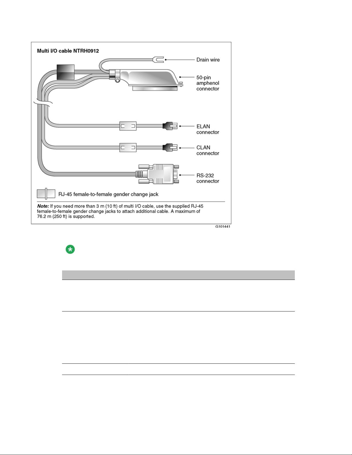
Multi I/O cable description
The following table identifies the purpose of each connector on the NTRH0912 multi I/O cable.
Note:
Labels on the RJ-45 cables distinguish the CLAN and ELAN connectors.
Connector type Purpose
50-pin amphenol This connector establishes the connection between the Meridian
1 or Communication Server 1000 Media Gateway or Media
Gateway Expansion backplane, ELAN and CLAN Ethernet hubs
or switches, and modem.
10Base-T (RJ-45) This connector provides a 10 Mbit/s Ethernet connection
between the 201i server and the Meridian 1 switch or
Communication Server 1000 system. This connection allows the
exchange of call control information between the server and the
Meridian 1 switch or Communication Server 1000 system.
For more information about the ELAN subnet, see the CallPilot
Installation and Configuration Task List.
10/100Base-T (RJ-45) This connector provides a network connection for
Avaya CallPilot® 201i Server Hardware Installation December 2010 23
Page 24

About the 201i server
Connector type Purpose
• user desktop computers, to enable use of the unified
messaging and fax messaging features
• LAN-based server administration
Important:
If you need Ethernet 100Base-T operation at 100 Mbit/s on
large Meridian 1 systems (such as Option 51), you must install
the NTRH3501 backplane (tip and ring) cable. For more
information, see Installing the 201i server in a large Meridian
1 system on page 37.
RS-232 COM1 (male
DB-9)
This connector provides the connection to an external modem.
The modem allows administrators and technical support
personnel to administer the 201i server from a remote location.
Peripheral connectivity
Introduction
Peripheral equipment is attached to the 201i server on the server faceplate.
Faceplate connections
Important:
Connections made to the faceplate (with the exceptions noted below) are temporary only,
because you must remove the cabinet cover to make these connections. The system does
not meet specifications for radiated EMI if you remove the cabinet cover.
The following peripheral devices connect to the 201i server faceplate:
• monitor (SVGA)
• keyboard
• mouse
• MPC card (permanent connection)
• SCSI cable (permanent connection)
24 Avaya CallPilot® 201i Server Hardware Installation December 2010
Page 25

Monitor, keyboard, and mouse
You must connect a monitor, keyboard, and mouse to run the Configuration Wizard or to install
the operating system on the 201i server as part of a recovery process.
All three peripheral components are hot-pluggable.
MPC-8 card
The MPC-8 card looks like a Type II PC card, and supports the multimedia telephony services
on the 201i server. Four specially-designed card slots are available for the MPC-8. All are
located on the 201i server faceplate.
Important:
You cannot insert MPC-8 cards in Type II PC card slots, or Type II PC cards into MPC-8
card slots. They are not compatible.
Monitor, keyboard, and mouse
SCSI connections
The SCSI connection is the only permanent faceplate connection. A low-profile right-angle
connector on the SCSI cable allows the cable to be attached with the cabinet covers on. For
more information about how the 201i server and SCSI device connections are achieved, see:
• large Meridian 1 systems (for example, Option 51C):
Meridian 1 on page 51.
• Option 11C or Option 11C Mini: Installing the NTRH3502 SCSI cable for Option 11C
Mini on page 65.
• Communication Server 1000:
Server 1000 on page 85.
Installing the SCSI cables for
Installing the NTRH3502 SCSI cable for Communication
Avaya CallPilot® 201i Server Hardware Installation December 2010 25
Page 26

About the 201i server
Supported peripheral devices
CD-ROM drive (NTRH9037)
An external CD-ROM drive is used to install and upgrade the server. The drive connects to the
server with an intermediate SCSI cable that connects to the SCSI connector on the faceplate.
Because the CD-ROM drive is an external device, it requires an AC power source.
Set the SCSI ID for the CD-ROM drive to 3. If you are connecting more than one SCSI device to
the server (such as a tape drive), you must daisy chain those devices.
Note:
The CD-ROM drive is not hot-pluggable. You must power off the server to connect or
disconnect the drive.
Tape drive (NTRH9038)
An external SCSI tape drive is used to back up and restore data. The device connects to the
server by an intermediate SCSI cable that connects to the SCSI connector on the faceplate.
Since the tape drive is an external device, it requires an AC power source.
Set the SCSI ID for the tape drive to 5. If you are connecting more than one SCSI device to
the server (such as a CD-ROM drive), you must daisy chain those devices.
Note:
The tape drive is not hot-pluggable. You must power off the server to connect or disconnect
the drive.
Modem
An external modem provides remote access to the 201i server. The modem connects to the
RS-232 COM1 connector on the multi I/O cable.
Since the modem is an external device, it requires its own AC power source.
26 Avaya CallPilot® 201i Server Hardware Installation December 2010
Page 27

The supported modem is the 56 Kbps modem (NTRH9078).
10Base-T Ethernet hub or switch
The 10Base-T Ethernet hub provides the ELAN subnet connection between the 201i server
and the Meridian 1 switch or Communication Server 1000 system.
Since the hub or switch is an external device, it requires an AC power source.
Monitor, keyboard, and mouse
• 15 in. monitor: NTRH9011 or N0038380 LCD monitor
Since the monitor is an external device, it requires an AC power source.
10Base-T Ethernet hub or switch
• Keyboard: NTRH9013
• Mouse: NTRH9014
Note:
The mouse connector on the 201i faceplate is a PS/2 connector. If you plan to use a USB
mouse with USB-to-PS/2 converter, you must also use the Avaya-supplied 101 mm (4-in)
PS/2 extension cable (A0855616). Without the extension cable, the monitor connector
partially blocks the mouse connector.
Avaya CallPilot® 201i Server Hardware Installation December 2010 27
Page 28

About the 201i server
28 Avaya CallPilot® 201i Server Hardware Installation December 2010
Page 29

Chapter 3: Preparing for installation
In this chapter
Installation overview on page 29
Unpacking and inspecting the 201i server on page 32
Switch and network requirements on page 34
Installation overview
Introduction
This section provides a high-level overview of the requirements and procedure for installing
the 201i server.
Before you begin
Ensure that proper power and grounding are available for all the power outlets serving the
Avaya CallPilot® server and its associated peripherals. Power for these devices must be wired
and fused independently of all other receptacles and referenced to the same ground as the
PBX system.
A qualified electrician must implement the single-point ground reference as required between
the power outlets of the Avaya CallPilot server and the power outlets of the switch.
Provide a sufficient number of properly grounded power outlets or power bars for all equipment.
For more information, refer to Chapter 2, "Grounding and power requirements", in the CallPilot
Planning and Engineering Guide.
Avaya CallPilot® 201i Server Hardware Installation December 2010 29
Page 30
Preparing for installation
Installation checklist
The following checklist identifies the steps required to install the 201i server and peripheral
devices. For more details, see Connecting peripheral devices to the 201i server on page
107.
Warning:
Risk of personal injury and hardware failure
The power outlets used by the CallPilot server and its peripheral devices must be connected
to the same ground reference as the one used by the Meridian 1 switch or Communication
Server 1000 system with MGate cards (NTRB18CA) connected to the CallPilot server. If this
requirement is not met, power transients can cause personal injury and hardware failure.
Step Description Check
1 Ensure that you have reviewed the "Installing CallPilot" section
in the CallPilot Installation and Configuration Task List and
completed stage 1 of the "Installation checklist."
This includes the following tasks:
Unpack the server, and ensure you have all the items you
need (see Unpacking and inspecting the 201i server on
page 32).
Complete the following checklists that are provided in the
CallPilot Installation and Configuration Task List:
- "CallPilot software media and documentation checklist"
- "CallPilot server hardware checklist"
Inspect the server for any damage that might have occurred
during shipping (see Unpacking and inspecting the 201i
server on page 32).
2 Familiarize yourself with the Switch and network
requirements on page 34 of this guide.
3 If you are installing the 201i server into a Meridian 1 tiered
system, do the following:
• Change the location of the secondary backplane (DS30X)
connector on the 201i server (see Repositioning the
secondary backplane connector on page 39).
• Replace the existing backplane (tip and ring) cable on the
Meridian 1 with the one supplied with the 201i server
(NTRH3501) (see pages Removing the backplane (tip and
ring) cables on page 44-What is next? on page 50).
4 Install the intermediate SCSI cable. This cable connects the
external CD-ROM or tape drive.
• For Meridian 1, you require two cables to complete the
connection between the 201i server and the SCSI device:
30 Avaya CallPilot® 201i Server Hardware Installation December 2010
Page 31

Step Description Check
NTRH1408 and NTRH1410. See Installing the SCSI cables
for Meridian 1 on page 51.
• For Option 11C, you require two cables to complete the
connection between the 201i server and the SCSI device:
NTRH1407 and NTRH3502. See Installing the intermediate
SCSI cable for Option 11C on page 60.
• For Option 11C Mini or Communication Server 1000, you
require one cable to complete the connection between the
201i server and the SCSI device: the NTRH3502 cable that is
provided in the CD-ROM and tape drive kits. See the
following:
- Option 11C Mini: Installing the NTRH3502 SCSI cable for
Option 11C Mini on page 65
- Communication Server 1000: Installing the NTRH3502
SCSI cable for Communication Server 1000 on page 85
5 Set the DIP switches on the modem (see Setting the modem
DIP switches on page 96).
Installation checklist
6 Set the following:
• SCSI IDs on the CD-ROM and tape drives (see pages Setting
the CD-ROM drive SCSI ID and DIP switches on page 98
and Setting the tape drive SCSI ID on page 100)
• DIP switches on the CD-ROM drive (see Setting the CD-
ROM drive SCSI ID and DIP switches on page 98)
• device termination on the CD-ROM and tape drives (see
Setting SCSI device termination on page 101)
7 Insert the 201i server into two consecutive slots inside the
switch. For instructions, see:
• large Meridian 1 systems, such as Option 51C (see Installing
the 201i server in the large Meridian 1 switch on page 43)
• Option 11C or Option 11C Mini (see Installing the 201i server
in the Option 11C or Option 11C Mini switch on page 57)
• Communication Server 1000 (see Installing the 201i server on
page 82)
8 Install the MPC cards, if required (see Installing the MPCs on
page 110).
9 Connect the 201i server and devices as follows:
Connect the monitor, keyboard, and mouse to the 201i server
faceplate (see Installing the monitor, keyboard, and mouse on
page 113).
Avaya CallPilot® 201i Server Hardware Installation December 2010 31
Page 32

Preparing for installation
Step Description Check
10 Complete the installation of the 201i server as follows:
Connect the CD-ROM and tape drives to the intermediate
SCSI cable (see Connecting the CD-ROM and tape drives on
page 114).
Connect the multi I/O cable to the ELAN and CLAN Ethernet
hubs or switches (see Connecting the 201i server to the
switch, ELAN subnet , and Avaya server subnet on
page 121).
Note:
If more than 3 m (10 ft) of multi I/O cable is required, use
the supplied RJ-45 female-to-female gender change jacks
to attach additional cable. Up to 76.2 m (250 ft) of cable
length is supported.
Connect the modem to the multi I/O cable (maximum length
15 m (50 ft) (see Connecting the modem on page 124).
Connect the power cords for all devices, and then power them
up.
• Connect the intermediate SCSI cable to the 201i server
faceplate.
• Close the lock latches on the 201i server.
• Boot the 201i server to the operating system.
See Completing the installation on page 126.
11 Continue with the CallPilot <switch model> and CallPilot Server
Configuration guide for your switch and server.
Unpacking and inspecting the 201i server
Introduction
This section describes how to:
• unpack the 201i server and peripherals
• inspect the 201i server for damage
It also describes what to do if you determine that the 201i server is faulty.
32 Avaya CallPilot® 201i Server Hardware Installation December 2010
Page 33

To inspect the 201i server for shipping damage
To unpack the 201i server
Important:
As you unpack each item, check it off against the packing list, as well as the following
checklists provided in the CallPilot Installation and Configuration Task List:
• "CallPilot software media and documentation checklist"
• "CallPilot server hardware checklist"
1. Remove the 201i server from the carton and its antistatic bag.
2. Place the 201i server on an antistatic surface.
3. Carefully open the cartons containing the monitor, keyboard, mouse, modem, and
ELAN hub (if supplied), and set the peripherals aside.
4. Put all manuals and CD-ROMs in a safe place.
5. Save all packing materials and cartons in case you must return any equipment to
the carrier.
6. Review
described in
201i server description on page 11, and perform a visual inspection as
To inspect the 201i server for shipping damage on page 33.
To inspect the 201i server for shipping damage
Before proceeding with the installation, visually inspect the 201i server for any damage that
might have occurred during shipping. Ensure also that the items in the following checklists are
secure:
Item Yes No
Are all cables securely seated?
hard drive power cable
hard drive data cable
See items 2 and 3 in the diagram in section Primary components on
page 14.
Is the hard drive and bracket interface secure? See items 6 and 7 in the
diagram in section Primary components on page 14.
Is the software feature key (dongle) securely seated in its bracket?
See 201i server components diagram in section Primary components on
page 14.
Avaya CallPilot® 201i Server Hardware Installation December 2010 33
Page 34

Preparing for installation
What to do if components are missing or damaged
IF THEN
you observe any damage contact your Avaya technical support
representative.
components have become loose secure them.
If necessary, refer to the procedures in the
CallPilot <server model> Server Maintenance
and Diagnostics guide for your server.
you are satisfied that the 201i server has
arrived at your site undamaged
you are ready to proceed with installation.
What is next?
Review the Switch and network requirements on page 34.
Switch and network requirements
Introduction
The information in this section will help you plan your 201i server installation.
Meridian 1 or Communication Server 1000 slot requirements
The 201i server occupies two physical and electrical slots.
Note:
You can place the unit in Slot 9 of an Option11C as the unit can function from slots 9 and
10. Do not place the unit in slot 10. Even though the unit can physically fit, there is no
electrical connection on the backplane to slot 11.
34 Avaya CallPilot® 201i Server Hardware Installation December 2010
Page 35

Meridian 1 I/O panel connections
You must install the 201i server in two peripheral equipment slots as follows:
Switch Slots
Meridian 1 tiered systems 0 through 14
Ensure that both slots have electrical backplane connectivity.
Option 11C 1 through 9 in any Option 11C cabinet
Option 11C Mini A pair of consecutive slots in any cabinet
Note:
You cannot install the 201i server in slots 0 or 4 because
these slots are dedicated to other cards. For more
information about cards and slots, refer to the Option 11C
Mini documentation.
Communication Server
1000
A pair of consecutive slots in any Media Gateway or Media
Gateway Expansion.
Note:
The 201i server cannot be installed in slots 0 or 4, because
these slots are dedicated to other cards. For more
information about cards and slots, refer to the
Communication Server 1000 Planning and Installation Guide
Meridian 1 I/O panel connections
On large Meridian 1 systems (such as Option 51C), the 201i server requires two connections
from the slots to the I/O panel on the rear of the switch, as follows:
• One connection is for the multi I/O cable.
This connection corresponds to the left slot (when viewing the front of the Meridian 1
switch).
• The other connection is for the external SCSI device.
This connection corresponds to the right slot (when viewing the front of the Meridian 1
switch).
For information about slot and rear bulkhead wiring, refer to the Meridian 1 System Installation
and Maintenance Guide
Avaya CallPilot® 201i Server Hardware Installation December 2010 35
Page 36

Preparing for installation
Avaya server subnet and ELAN subnet requirements
The ELAN subnet and the Avaya server subnet must be configured and the appropriate
networking equipment must be available.
If the Avaya server subnet is to be part of the customer LAN, you need a network specialist to
ensure proper configuration.
Important:
For important considerations about using the ELAN in your network, see theCallPilot
Installation and Configuration Task List.
What is next?
Install the 201i server in the Meridian 1 switch or Communication Server 1000 system. For
instructions, see one of the following:
To install the 201i server in See
a large Meridian 1 switch (for example,
Option 51C)
an Option 11C or Option 11C Mini switch Installing the 201i server in an Option 11C or
the Communication Server 1000 system Installing the 201i server in the Avaya
Installing the 201i server in a large Meridian
1 system on page 37
Option 11C Mini on page 57
Communication Server 1000 system on
page 75
36 Avaya CallPilot® 201i Server Hardware Installation December 2010
Page 37

Chapter 4: Installing the 201i server in a
large Meridian 1 system
in this chapter
Overview on page 37
Repositioning the secondary backplane connector on page 39
Installing the 201i server in the large Meridian 1 switch on page 43
Removing the backplane (tip and ring) cables on page 44
Installing the NTRH3501 backplane cable on page 48
Installing the SCSI cables for Meridian 1 on page 51
Overview
Introduction
This section describes how to install the 201i server in a Meridian 1 switch.
Important:
To install the 201i server in an Option 11C, go to Installing the 201i server in the large
Meridian 1 switch on page 43. For Option 11C Mini, go to Section B: Installing Option 11C
Mini cables on page 65. For Communication Server 1000, go to Installing the 201i server in
the Avaya Communication Server 1000 system on page 75.
Avaya CallPilot® 201i Server Hardware Installation December 2010 37
Page 38

Installing the 201i server in a large Meridian 1 system
Meridian 1 I/O panel connections
On the Meridian 1, the 201i server requires two connections from the slots to the I/O panel on
the rear of the switch, as follows:
• One connection is for the multi I/O cable.
This connection corresponds to the left slot (when viewing the front of the Meridian 1
switch).
• The other connection is for the external SCSI device.
This connection corresponds to the right slot (when viewing the front of the Meridian 1
switch).
For information about slot and rear bulkhead wiring, refer to the Meridian 1 System Installation
and Maintenance Guide
Secondary backplane connector
The secondary backplane (DS30X) connector on the 201i server connects the server to the
second slot on the shelf, thereby providing access to the voice channels provided by that slot.
Caution:
Risk of equipment damage
The 201i server is shipped ready for installation into an Option 11C switch. Before you install
the 201i server in a larger Meridian 1 switch (for example, Option 51C), you must move the
secondary backplane (DS30X) connector to the correct position.
Important:
A yellow warning label over the top lock latch on the 201i server prevents you from securing
the 201i server in a slot. This label serves as a reminder to move the secondary backplane
connector to the Meridian 1 position, if required, before installing the 201i server into the slot.
Backplane (tip and ring) cable
The backplane (tip and ring) cable supplied with the 201i server (NTRH3501) provides
100Base-T Ethernet operation for the Avaya server subnet. This cable offers more network
throughput than the cable that is already installed on the Meridian 1.
38 Avaya CallPilot® 201i Server Hardware Installation December 2010
Page 39

When installed, this cable completes the connection between the left slot, the I/O panel on the
rear of the switch, and the multi I/O cable on the 201i server.
SCSI cables
Before you can connect a CD-ROM or tape drive to the 201i server, you must install the SCSI
cables. You require two cables. These cables route the SCSI connection away from the 201i
server faceplate so that an external SCSI device can remain permanently connected.
Repositioning the secondary backplane connector
SCSI cables
Introduction
The secondary backplane (DS30X) connector on the 201i server connects the server to the
second slot on the shelf, thereby providing access to the voice channels provided by that slot.
Caution:
Risk of equipment damage
The 201i server ships ready for installation into an Option 11C or Option 11C Mini switch.
Before you install the 201i server in a larger Meridian 1 switch (for example, Option 51C),
you must move the secondary backplane (DS30X) connector to the correct position.
Why you must move the connector
There is an approximate difference of 2 mm (0.08 in) between slots on a Meridian 1 tiered
system and an Option 11C or Option 11C Mini system. As a result, you must install the
secondary backplane (DS30X) connector on the 201i server in the correct position before a
successful connection with the switch backplane can be established.
Important:
A yellow warning label over the top lock latch on the 201i server prevents you from securing
the 201i server in a slot. This label serves as a reminder to move the secondary backplane
connector to the Meridian 1 position, if required, before installing the 201i server into the slot.
Avaya CallPilot® 201i Server Hardware Installation December 2010 39
Page 40

Installing the 201i server in a large Meridian 1 system
Secondary backplane connector description
The secondary backplane connector is attached to the backplane edge of the 201i server. It
consists of the following items:
• connector
• screws
• pin connector (with four pins)
Two pairs of screw holes are provided for connecting the secondary backplane connector to
the 201i server stiffening cage. The outside pair provides the Meridian 1 spacing. The inside
pair provides the Option 11C or Option 11C Mini spacing.
See the following diagram:
40 Avaya CallPilot® 201i Server Hardware Installation December 2010
Page 41

Required equipment
To move the secondary backplane connector, you need a Phillips No. 1 screwdriver. A pair of
needle-nosed pliers can also be helpful for removing the pin connector.
To prepare the 201i server for installation in a Meridian 1 switch
1. Remove the secondary backplane pin connector.
The pin connector has four pins. If necessary, use needle-nosed pliers to remove it.
2. Remove the top and bottom screws that hold the secondary backplane connector
in place on the stiffening cage.
3. Loosen the middle screw, and then align the outside pair of screw holes on the
bracket with the matching pair on the stiffening cage.
4. Replace and alternately tighten all screws until the connector is evenly and securely
fastened.
Required equipment
See the following diagram:
Avaya CallPilot® 201i Server Hardware Installation December 2010 41
Page 42

Installing the 201i server in a large Meridian 1 system
5. Replace the pin connector so the pins protrude through both connectors.
Ensure that the connectors are correctly aligned as shown in the diagram below.
Caution:
Risk of equipment damage
42 Avaya CallPilot® 201i Server Hardware Installation December 2010
Page 43

What is next?
6. Gently press the pin connector into the socket until it is fully seated.
7. Remove the yellow backplane warning label from the top lock latch on the 201i
server.
What is next?
Continue with Installing the 201i server in the large Meridian 1 switch on page 43.
Installing the 201i server in the large Meridian 1 switch
Introduction
The 201i server occupies two slots. You can install the 201i server in slots 0 through 14. Ensure
that both slots have electrical backplane connectivity.
Avaya CallPilot® 201i Server Hardware Installation December 2010 43
Page 44

Installing the 201i server in a large Meridian 1 system
To position the 201i server on the switch shelf
1. Ensure that no cables are connected to the slots in which you are installing the 201i
server.
2. Open the lock latches at the top and bottom of the 201i server faceplate.
Note:
When you open the top lock latch, you break the yellow backplane warning label,
if it has not been removed. You must move the secondary backplane connector
before you install the 201i server. For details, see Repositioning the secondary
backplane connector on page 39.
3. Slide the 201i server into an unoccupied pair of slots.
Ensure that the 201i server is positioned correctly between the slots.
Important:
Do not push the 201i server into place against the backplane until you are ready to
observe the startup cycle.
The 201i server receives power and starts as soon as the 201i server makes
contact with the switch backplane.
4. Connect the low-profile right-angle SCSI cable connector to the SCSI connector on
the 201i server faceplate.
What is next?
Continue with Removing the backplane (tip and ring) cables on page 44.
Removing the backplane (tip and ring) cables
Introduction
You must remove the Meridian 1 backplane (tip and ring) cables that are associated with the
slots occupied by the 201i server so that you can install the following cables:
• NTRH3501 backplane (tip and ring) cable
44 Avaya CallPilot® 201i Server Hardware Installation December 2010
Page 45

The NTRH3501 cable offers more network throughput than the cable that is already
installed on the Meridian 1. This cable is connected to the backplane connectors and I/
O panel slot associated with the left slot.
• NTRH1408 intermediate SCSI cable
The NTRH1408 intermediate SCSI cable routes the SCSI device connection away from
the 201i server faceplate so that an external SCSI device can remain permanently
connected. This cable is connected to the I/O panel only. The backplane connectors
associated with the right slot are left vacant.
These cables are supplied with the 201i server.
Before you begin
Voltage:
Risk of electrical shock
Before you begin
Ensure that the shelf is powered off before you remove the backplane cables.
Note:
For information about slot and rear bulkhead wiring and powering off the shelf, refer to the
Meridian 1 System Installation and Maintenance Guide
To remove the backplane cables
1. Remove the I/O panel cover from the rear of the Meridian 1 switch.
2. Remove the protective plate from the rear of the Meridian 1 switch.
Avaya CallPilot® 201i Server Hardware Installation December 2010 45
Page 46

Installing the 201i server in a large Meridian 1 system
3. Remove the existing backplane cable, including the I/O filter assembly (NT8D81xx)
and mounting hardware for the left slot as follows:
a. Remove the external cable attached to the outside of the I/O panel.
b. For each of the UP 1, UP 2, and UP 3 cable connectors, push the lock
tab outwards to unlock the cable connection, and then pull the connector
off.
Important:
If you attempt to pull the connector off without pressing the lock tab,
you can pull the connector shroud off the backplane. If this happens,
refer to the adjacent connectors for correct key positioning, and then
replace the connector shroud.
Remove the tie wraps where applicable to free the cable.
c. Remove the connector, I/O filter assembly, and all mounting hardware
from the inside of the I/O panel so the slot is completely vacated.
Retain the mounting hardware (that is, screws, tie wrap base, standoffs,
and so on). You will reuse this hardware to fasten the NTRH3501 cable.
4. Repeat step
3 on page 46 to remove the existing backplane cable for the right slot.
Store the cable, I/O filter assembly, and mounting hardware for this cable with your
Meridian 1 spares. You will not use them with the 201i server.
The following diagram shows an example using slots 3 and 4:
46 Avaya CallPilot® 201i Server Hardware Installation December 2010
Page 47

What is next?
What is next?
Continue with Installing the NTRH3501 backplane cable on page 48.
Avaya CallPilot® 201i Server Hardware Installation December 2010 47
Page 48

Installing the 201i server in a large Meridian 1 system
Installing the NTRH3501 backplane cable
Introduction
You must connect the backplane (tip and ring) cable supplied with the 201i server (NTRH3501)
for 100Base-T Ethernet operation to the Avaya server subnet. This cable offers more network
throughput than the cable you just removed from the Meridian 1.
When installed, this cable completes the connection between the left slot, the I/O panel on the
rear of the switch, and the multi I/O cable on the 201i server.
Backplane (tip and ring) cable
The following diagram shows the NTRH3501 backplane (tip and ring) cable:
48 Avaya CallPilot® 201i Server Hardware Installation December 2010
Page 49

Before you begin
Before you can install the NTRH3501 cable, you must remove the existing backplane cable
from the back of the switch. See Removing the backplane (tip and ring) cables on page 44.
To install the NTRH3501 backplane cable
Install and connect the NTRH3501 cable to the multi I/O cable as follows:
a. Attach the backplane connector of the NTRH3501 cable to the inside of the
b. Attach the three inner cables to the backplane connectors associated with
Before you begin
I/O panel slot associated with the 201i server left slot.
Insert the original screw into the tie wrap base and fasten the screw into the
lower position of the I/O panel slot.
the left slot as follows:
• UP 1 cable to the top position
• UP 2 cable to the middle position
• UP 3 cable to the lower position
Important:
The connectors are keyed; you can insert them in one position only.
Use tie wraps to secure the cables in their original positions.
c. Connect the 50-pin amphenol connector on the multi I/O cable (NTRH0912)
to the NTRH3501 backplane cable connector on the I/O panel.
See the following diagram:
Avaya CallPilot® 201i Server Hardware Installation December 2010 49
Page 50

Installing the 201i server in a large Meridian 1 system
What is next?
Continue with Installing the SCSI cables for Meridian 1 on page 51.
50 Avaya CallPilot® 201i Server Hardware Installation December 2010
Page 51

Installing the SCSI cables for Meridian 1
Installing the SCSI cables for Meridian 1
Introduction
Before you can connect a CD-ROM or tape drive to the 201i server, you must install the SCSI
cables. The SCSI cables route the SCSI connection away from the 201i server faceplate so
that an external SCSI device can remain permanently connected.
Caution:
Risk of equipment damage
You must power off the 201i server before connecting or disconnecting SCSI cables.
Cables you need
You require the following cables:
• NTRH1408 (for connecting the 201i server to the Meridian 1 I/O panel)
The connector on the intermediate SCSI cable that attaches to the 201i server faceplate is
a low-profile right-angle connector. This allows the cable to be attached with the Meridian
1 cabinet cover on.
Avaya CallPilot® 201i Server Hardware Installation December 2010 51
Page 52

Installing the 201i server in a large Meridian 1 system
• NTRH1410 (for connecting an external SCSI device to the NTRH1408 connector on the
Meridian 1 I/O panel)
The total length of the cable from the I/O panel is 4.1 m (13.3 ft).
What the completed installation looks like
The following diagram shows how the intermediate SCSI cable, CD-ROM drive, and tape drive
are connected to the Meridian 1.
In this diagram, the CD-ROM drive is the first device. The tape drive is the last device.
52 Avaya CallPilot® 201i Server Hardware Installation December 2010
Page 53

Before you begin
Note:
Alternate SCSI device connection scenarios are supported, but are not depicted in this
guide. If you want to use a connection scenario that is not described in this guide, ensure
that you use appropriate cabling for each device.
Before you begin
Before you install the SCSI devices in a daisy chain, you must configure the SCSI device IDs
and DIP switches. For instructions, refer to Preparing peripheral devices on page 95.
To install the SCSI cables for Meridian 1
1. Thread the SCSI connector end of the NTRH1408 cable from the front of the
Meridian 1 along the bottom of the shelf to either the left or the right access channel.
2. Leave the low-profile right-angle SCSI connector hanging for now. You will connect it
later to the 201i server faceplate.
Note:
The following diagram shows what the connection looks like after the cable is
connected:
Avaya CallPilot® 201i Server Hardware Installation December 2010 53
Page 54

Installing the 201i server in a large Meridian 1 system
3. Thread the cable through the access channel to the back of the Meridian 1.
4. Attach the NTRH1408 cable to the inside of the I/O panel slot associated with the
201i server right slot.
5. Connect the NTRH1410 cable to the NTRH1408 cable connector on the I/O panel.
See the following diagram:
54 Avaya CallPilot® 201i Server Hardware Installation December 2010
Page 55

What is next?
6. Thread the NTRH1410 cable through the shelves below and out through the bottom
of the Meridian 1 tower.
7. Replace the protective plate.
8. Replace the I/O panel cover.
9. Power up the shelf.
What is next?
Prepare the modem, CD-ROM drive, and tape drive for connection to the 201i server. For
instructions, see Preparing peripheral devices on page 95.
Note:
The backplane connectors for the right slot are not required and, therefore, are
left vacant.
Avaya CallPilot® 201i Server Hardware Installation December 2010 55
Page 56

Installing the 201i server in a large Meridian 1 system
56 Avaya CallPilot® 201i Server Hardware Installation December 2010
Page 57

Chapter 5: Installing the 201i server in an
Option 11C or Option 11C Mini
In this chapter
Installing the 201i server in the Option 11C or Option 11C Mini switch on page 57
Section A: Installing Option 11C cables on page 60
Installing the intermediate SCSI cable for Option 11C on page 60
Section B: Installing Option 11C Mini cables on page 65
Installing the NTRH3502 SCSI cable for Option 11C Mini on page 65
Installing cables on the back of the Option 11C Mini cabinet on page 71
Installing the 201i server in the Option 11C or Option 11C Mini switch
Introduction
The 201i server occupies physical and electrical slots. The 201i server must be installed in two
peripheral equipment slots as follows:
Switch Eligible slots
Option 11C Slots 1 through 9 in any cabinet
Option 11C Mini A pair of consecutive slots in any cabinet
Note:
You cannot install the 201i server in slots 0 or 4,
because these slots are dedicated to other cards.
Avaya CallPilot® 201i Server Hardware Installation December 2010 57
Page 58

Installing the 201i server in an Option 11C or Option 11C Mini
Switch Eligible slots
For more information about cards and slots, refer to
the Option 11C Mini documentation.
To position the 201i server on the switch shelf
1. Remove the front panel of the switch.
Note:
On the Option 11C Mini, do the following:
a. Loosen the spring-loaded clips.
b. Slide the cover to the left.
c. Pull the cover up to remove it from the cabinet.
See the following diagram:
2. Ensure that no cables are connected to the slots in which you are installing the 201i
server.
3. Open the lock latches at the top and bottom of the 201i server faceplate.
58 Avaya CallPilot® 201i Server Hardware Installation December 2010
Page 59

Note:
When you open the top lock latch, it breaks the yellow backplane warning label, if
the label has not been removed. The label is not relevant for Option 11C or Option
11C Mini. Remove the label and continue with this procedure.
4. Slide the 201i server into an unoccupied pair of slots.
Ensure that the 201i server is positioned correctly between the slots.
Note:
When correctly inserted in the Option 11C Mini, the top of the 201i server is on
the left. See the following diagram:
Introduction
Important:
Do not push the 201i server into place against the backplane until you are ready to
observe the startup cycle.
The 201i server receives power and starts as soon as the 201i server makes
contact with the switch backplane.
Avaya CallPilot® 201i Server Hardware Installation December 2010 59
Page 60

Installing the 201i server in an Option 11C or Option 11C Mini
What is next?
Continue with installing the cables. Refer to one of the following:
• Section A: Installing Option 11C cables on page 60
• Section B: Installing Option 11C Mini cables on page 65
Section A: Installing Option 11C cables
In this section
Installing the intermediate SCSI cable for Option 11C on page 60
Installing the intermediate SCSI cable for Option 11C
Introduction
Before you can connect an external CD-ROM or tape drive to the 201i server, Option 11C
requires an intermediate SCSI cable (NTRH1407).
Note:
If you are installing the 201i server in an Option 11C Mini, go to Installing the NTRH3502
SCSI cable for Option 11C Mini on page 65.
Cable description
The connector on the NTRH1407 cable that attaches to the 201i server faceplate is a lowprofile right-angle connector. This allows the SCSI device to be permanently connected to the
201i server with the Option 11C cabinet cover on.
60 Avaya CallPilot® 201i Server Hardware Installation December 2010
Page 61

What the completed installation looks like
The SCSI device connector end is equipped with a bracket assembly. This bracket assembly
attaches to the Option 11C below the card cage. The CD-ROM or tape drive connects to this
bracket assembly with the NTRH3502 cable that is provided with the device.
What the completed installation looks like
The following diagram shows how the intermediate SCSI cable, CD-ROM drive, and tape drive
are connected to the Option 11C. The CD-ROM drive is the first device. The tape drive is the
last device.
Avaya CallPilot® 201i Server Hardware Installation December 2010 61
Page 62

Installing the 201i server in an Option 11C or Option 11C Mini
Note:
Alternate SCSI device connection scenarios are supported, but are not depicted in this
guide. If you want to use a connection scenario that is not described in this guide, ensure
that you use appropriate cabling for each device.
Before you begin
Before you install the SCSI devices in a daisy chain, you must configure the SCSI device IDs
and DIP switches. For instructions, see Preparing peripheral devices on page 95.
To install the cable
1.
Caution:
Risk of equipment damage
You must power off the 201i server before connecting or disconnecting SCSI
cables.
Attach the bracket assembly and cable as follows:
a. Below the card cage, temporarily remove the hardware that secures
cable connections to the Option 11C.
b. Temporarily remove any cabling that may interfere with the installation
of the intermediate SCSI cable bracket assembly.
62 Avaya CallPilot® 201i Server Hardware Installation December 2010
Page 63

Important:
Before you disconnect the cabling, take the telephony equipment
services associated with the cabling out of service.
c. Remove the two screws on the right side of the Option 11C I/O panel.
d. Attach the intermediate SCSI cable bracket assembly, using the screws
that were removed previously, so that the SCSI connector appears on
the right side of the Option 11C cabinet.
See the following diagram:
Before you begin
2. Thread the cable up through the card cage.
Note:
When routing the SCSI cable through the card cage, ensure the second cable
ferrite is placed halfway through the opening.
3. Connect the grounding braid on the intermediate SCSI cable to the card cage, and
tighten the screw.
Avaya CallPilot® 201i Server Hardware Installation December 2010 63
Page 64

Installing the 201i server in an Option 11C or Option 11C Mini
4. Leave the low-profile right-angle SCSI connector loose for now. You will connect it
later to the 201i server faceplate.
Note:
The following diagram shows what the connection looks like after the cable is
connected:
5. Replace all cabling and hardware that you removed in step 1 on page 62.
6. Restore any services that you took out of service in step
1 on page 62.
What is next?
Prepare the modem, CD-ROM drive, and tape drive for connection to the 201i server. For
instructions, see Preparing peripheral devices on page 95.
64 Avaya CallPilot® 201i Server Hardware Installation December 2010
Page 65

Section B: Installing Option 11C Mini cables
Section B: Installing Option 11C Mini cables
In this section
Installing the NTRH3502 SCSI cable for Option 11C Mini on page 65
Installing cables on the back of the Option 11C Mini cabinet on page 71
Installing the NTRH3502 SCSI cable for Option 11C Mini
Introduction
Before you can connect a CD-ROM or tape drive to the 201i server, you must install the
NTRH3502 SCSI cable. The NTRH3502 SCSI cable routes the SCSI connection away from
the 201i server faceplate so that an external SCSI device can remain permanently connected.
If the Option 11C Mini is equipped with a Fiber Routing Guide (consisting of a spool and
mounting bracket), you must remove it before you can install the NTRH3502 SCSI cable, and
then reinstall it when you are finished.
For detailed instructions on removing and installing the Fiber Routing Guide, refer to the Option
11C and Option 11C Mini Expansion Guide
What the completed installation looks like
The following diagram shows how the intermediate SCSI cable, CD-ROM drive, and tape drive
are connected to the Option 11C Mini. In the diagram, the CD-ROM drive is the first device.
The tape drive is the last device.
Avaya CallPilot® 201i Server Hardware Installation December 2010 65
Page 66

Installing the 201i server in an Option 11C or Option 11C Mini
Note:
Alternate SCSI device connection scenarios are supported, but are not depicted in this
guide. If you want to use a connection scenario that is not described in this guide, ensure
that you use appropriate cabling for each SCSI device.
Before you begin
Before you install the SCSI devices in a daisy chain, you must configure the SCSI
device IDs and DIP switches.
For instructions, see Preparing peripheral devices on page 95.
To install the NTRH3502 SCSI cable
1.
Caution:
Risk of equipment damage
You must power off the 201i server before connecting or disconnecting SCSI
cables.
If your Option 11C Mini is equipped with a Fiber Routing Guide, temporarily remove
it.
66 Avaya CallPilot® 201i Server Hardware Installation December 2010
Page 67

Before you begin
Note:
For detailed instructions, refer to the Option 11C and Option 11C Mini Expansion
Guide
See the following diagram:
2. Remove the inner SCSI bracket from the inside of the cabinet.
See the following diagram:
Avaya CallPilot® 201i Server Hardware Installation December 2010 67
Page 68

Installing the 201i server in an Option 11C or Option 11C Mini
3. Refasten the inner SCSI bracket screws in their original locations inside the cabinet.
You will use the top screw later to fasten the NTRH3502 SCSI cable drain wire.
4. Connect the low-profile right-angle SCSI connector on the NTRH3502 cable to the
SCSI connector on the 201i server faceplate.
5. Fasten the SCSI cable drain wire to the top screw that previously held the inner
SCSI bracket in place.
68 Avaya CallPilot® 201i Server Hardware Installation December 2010
Page 69

Before you begin
Figure 2: SCSI cable installation to accommodate the Fiber Routing Guide
6. If required, reinstall the Fiber Routing Guide.
Note:
For detailed instructions, refer to the Option 11C and Option 11C Mini Expansion
Guide
See the following diagram:
Avaya CallPilot® 201i Server Hardware Installation December 2010 69
Page 70

Installing the 201i server in an Option 11C or Option 11C Mini
7. Replace the cabinet cover.
What is next?
Continue with
Installing cables on the back of the Option 11C Mini cabinet on page 71.
70 Avaya CallPilot® 201i Server Hardware Installation December 2010
Page 71

Installing cables on the back of the Option 11C Mini cabinet
Installing cables on the back of the Option 11C Mini cabinet
Introduction
The following items connect to the back of the Option 11C Mini cabinet:
• multi I/O cable (NTRH0912)
• Option 11C Mini power cord with two ferrites
You must connect the multi I/O cable first before connecting the power cord, because the power
cord routes over the multi I/O cable connection.
To connect the cables
1. On the rear of the Option 11C Mini cabinet, locate the connector associated with
the first slot occupied by the 201i server.
2. Connect the NTRH0912 multi I/O cable as follows:
a. Loosen the connector's Velcro fastening strap.
b. Connect the amphenol connector on the NTRH0912 multi I/O cable to
the connector on the back of the Option 11C Mini cabinet.
c. Secure the connection by tightening the retaining screw and Velcro
fastening strap of the connector.
The following diagram shows how to secure the multi I/O cable connection:
Avaya CallPilot® 201i Server Hardware Installation December 2010 71
Page 72

Installing the 201i server in an Option 11C or Option 11C Mini
3. Attach the multi I/O cable drain wire to a screw on the cabinet.
See the diagram in step
4 on page 72.
4. Connect the power cord to the Option 11C Mini cabinet.
See the following diagram:
72 Avaya CallPilot® 201i Server Hardware Installation December 2010
Page 73

What is next?
What is next?
Prepare the modem, CD-ROM drive, and tape drive for connection to the 201i server. For
instructions, see Preparing peripheral devices on page 95.
Avaya CallPilot® 201i Server Hardware Installation December 2010 73
Page 74

Installing the 201i server in an Option 11C or Option 11C Mini
74 Avaya CallPilot® 201i Server Hardware Installation December 2010
Page 75

Chapter 6: Installing the 201i server in the
Avaya Communication Server
1000 system
In this chapter
Communication Server 1000 description on page 75
Removing the Media Gateway or Media Gateway Expansion cover on page 80
Installing the 201i server on page 82
Installing the NTRH3502 SCSI cable for Communication Server 1000 on page 85
Replacing the Media Gateway or Media Gateway Expansion cover on page 88
Connecting cables to the Communication Server 1000 system on page 91
Communication Server 1000 description
Introduction
The Communication Server 1000 system is an IP PBX that provides telephony and data
capabilities over an IP network. The Communication Server 1000 system consists of the
following major components:
• Call Server
• Media Gateway
• Media Gateway Expansion
Avaya CallPilot® 201i Server Hardware Installation December 2010 75
Page 76

Installing the 201i server in the Avaya Communication Server 1000 system
Call Server
The Call Server provides telephony services and call processing.
It supports up to four Media Gateways and four Media Gateway Expansions when the Small
System Controller (SSC) card inside the unit is fully populated with two dual-port 100BaseT
daughterboards.
The following connectors are located on the back of the Call Server:
• four 100Base-T connectors for connecting Media Gateways using one of the following:
- for connections over the LAN customer-supplied standard 100Base-T CAT5
Ethernet cables
- for point-to-point connections (Avaya-supplied crossover Ethernet cables)
• one 10Base-T Ethernet connector that
- provides the ELAN subnet interface to management software applications, such as
Optivity Telephony Manager and Avaya CallPilot
- accepts an industry-standard Medium Access Unit (MAU)
• one SDI connector that interfaces with three TTY ports using a three-port SDI cable
• one AC power cord connector and On/Off switch
The following diagram shows the Call Server:
®
76 Avaya CallPilot® 201i Server Hardware Installation December 2010
Page 77

Media Gateway and Media Gateway Expansion
Media Gateway and Media Gateway Expansion
The Media Gateway and Media Gateway Expansion provide the interface for analog or digital
trunks, i2004 Internet telephones, analog telephones, and applications such as Avaya
CallPilot.
A Media Gateway Expansion can be connected to the Media Gateway to increase system
capacity.
Card slots
The 201i server occupies physical and electrical slots. You must install the 201i server in a pair
of consecutive slots in the Media Gateway or Media Gateway Expansion.
The following table identifies the Media Gateway and Media Gateway Expansion slots into
which you can install the CallPilot 201i server:
Unit The 201i server can be
Media Gateway Slots 1 and 2
Slots 2 and 3
Slots 3 and 4
Media Gateway
Expansion
For more information about cards and slots, refer to the Communication Server 1000 Planning
and Installation Guide
Slots 7 and 8
Slots 8 and 9
Slots 9 and 10
Back panel connectors
The following table describes the connectors that are located on the back of each Media
Gateway and Media Gateway Expansion, and how they relate to CallPilot:
Ineligible slots
installed in
Slot 0 is dedicated to the SSC card.
Slot 10 is a double-wide slot. The
second half of this slot does not
have a backplane connector.
Avaya CallPilot® 201i Server Hardware Installation December 2010 77
Page 78

Installing the 201i server in the Avaya Communication Server 1000 system
Connector Media
Gateway
Four 50-pin amphenol connectors that interface with the
cross-connect terminal.
The CallPilot 201i server multi I/O cable must be
connected to the connector that is associated with the
first slot that the 201i server occupies. This is described
in Connecting cables to the Communication Server 1000
system on page 91.
One auxiliary (AUX) connector yes no
One SDI connector yes no
One 10Base-T Ethernet connector that
• provides the ELAN subnet interface to management
software applications such as Optivity Telephony
Manager and CallPilot
• accepts an industry-standard Medium Access Unit
(MAU)
DS30X and CE-MUX connectors for connecting the
Media Gateway and Media Gateway Expansions
together
yes yes
yes no
yes yes
Media
Gateway
Expansion
Power connector yes yes
The following diagram shows the Media Gateway:
78 Avaya CallPilot® 201i Server Hardware Installation December 2010
Page 79

Communication Server 1000 software
Note:
Except for the back panel connectors, the Media Gateway Expansion is similar in external
appearance to the Media Gateway.
Communication Server 1000 software
For the 201i server, the Communication Server 1000 system must be running Communication
Server Release 3.00 (or later) software.
The Media Gateways and Media Gateway Expansions are centrally configured from the Call
Server. This allows for a single point of management. Configuration required for correct
CallPilot operation is, therefore, performed on the Call Server.
Administration software
The Communication Server 1000 system interfaces with Optivity Telephony Manager Release
1.1 (or later). Optivity Telephony Manager is an integrated suite of system management tools.
You can use Optivity Telephony Manager to configure, control, and manage your
Communication Server 1000 system. Optivity Telephony Manager operates on a platform that
is compatible with a standard Windows PC.
Avaya CallPilot® 201i Server Hardware Installation December 2010 79
Page 80

Installing the 201i server in the Avaya Communication Server 1000 system
Refer to the Optivity Telephony Manager documentation for information about the Optivity
Telephony Manager application, its requirements, and how to install it.
Communication Server 1000 documentation
If you need to refer to the following Communication Server 1000 technical documents, they
are stored on the Customer Documentation Library CD-ROM (NTLH80BA), provided with your
Communication Server 1000 system:
• Communication Server 1000 Planning and Installation Guide
Note:
This guide is also provided in printed format with your Communication Server 1000
system.
• Communication Server 1000 Input/Output X21 Administration
• Communication Server 1000 Input/Output X21 Maintenance
You can search the entire suite of documentation online, or you can print part or all of a guide.
Removing the Media Gateway or Media Gateway Expansion cover
Introduction
To access the interior of the Media Gateway or Media Gateway Expansion, you must remove
the front bezel and inside front cover plate.
To remove the front bezel and inside front cover plate
1.
Warning:
Risk of eye injury
Avaya recommends that you operate the Media Gateway and Media Gateway
Expansion with their front bezels installed. When the blue LEDs inside these units
are lit, they are very bright.
80 Avaya CallPilot® 201i Server Hardware Installation December 2010
Page 81

Introduction
Remove the front bezel from the Media Gateway or Media Gateway Expansion as
shown in the diagram on the next page.
a. Use a slot screwdriver to gently pry off the label.
b. Insert the screwdriver approximately 2 cm (0.75 in.) into the open slot,
and then gently lift the screwdriver handle, thus applying downward
pressure on the tab inside the bezel.
At the same time, gently pull the bezel away from the chassis
(approximately 2 cm [0.75 in.]) until the inside tab has cleared the catch.
c. Grasp the bezel by both sides and carefully pull it straight away from the
Media Gateway or Media Gateway Expansion.
2. Remove the inside front cover plate as follows:
Avaya CallPilot® 201i Server Hardware Installation December 2010 81
Page 82

Installing the 201i server in the Avaya Communication Server 1000 system
a. Use a screwdriver to loosen each screw on the top of the inside front
cover plate by three turns.
Important:
Do not remove the screws.
b. Apply pressure and slide the inside front cover plate upward to the left
until the screw holes are aligned with the screw heads.
c. Pull the inside front cover plate away from the Media Gateway or Media
Gateway Expansion.
What is next?
Continue with Installing the 201i server on page 82.
Installing the 201i server
Introduction
This section describes how to install the 201i server inside the Media Gateway or Media
Gateway Expansion.
82 Avaya CallPilot® 201i Server Hardware Installation December 2010
Page 83

Before you begin
Determine which pair of consecutive slots are to contain the 201i server. The following table
identifies the Media Gateway and Media Gateway Expansion slots into which the CallPilot 201i
server can be installed:
Before you begin
Unit The 201i server can be
installed in
Media Gateway Slots 1 and 2
Slots 2 and 3
Media Gateway
Expansion
Slots 7 and 8
Slots 8 and 9
Slots 9 and 10
Slot 0 is dedicated to the SSC card.
Slot 4 (includes slots 5 and 6) is not
used.
Slot 10 is a double-wide slot. The
second half of this slot does not
have a backplane connector.
Ineligible slots
Note:
The 201i server will not function properly when installed in slots 3 and 4.
For more information about card slots, refer to the Communication Server 1000 Planning and
Installation Guide
For the logical slot numbers that you must use when you configure the Communication Server
1000 system, see Card slots on page 77.
To install the 201i server inside the Media Gateway or Media Gateway Expansion
1. Ensure that no cables are connected to the slots in which you are installing the 201i
server.
2. Open the lock latches at the top and bottom of the 201i server faceplate.
Note:
When you open the top lock latch, it breaks the yellow backplane warning label
if it has not been removed. The label is not relevant for Communication Server
1000. Remove the label and continue with this procedure.
3. Slide the 201i server into an unoccupied pair of slots.
Ensure that the 201i server is positioned correctly between the slots.
When correctly inserted, the top of the 201i server is on the left. See the following
diagram:
Avaya CallPilot® 201i Server Hardware Installation December 2010 83
Page 84

Installing the 201i server in the Avaya Communication Server 1000 system
What is next?
Continue with
page 85.
Important:
Do not push the 201i server into place against the backplane until you are ready to
observe the startup cycle.
If the Media Gateway or Media Gateway Expansion is connected to a power
source, the 201i server receives power as soon as it makes contact with the
backplane.
Installing the NTRH3502 SCSI cable for Communication Server 1000 on
84 Avaya CallPilot® 201i Server Hardware Installation December 2010
Page 85

Installing the NTRH3502 SCSI cable for Communication Server 1000
Installing the NTRH3502 SCSI cable for Communication
Server 1000
Introduction
Before you can connect a CD-ROM or tape drive to the 201i server, you must install the
NTRH3502 SCSI cable. The NTRH3502 SCSI cable has a low profile right-angle connector
that allows the cable to be connected to the 201i server faceplate when the Media Gateway
or Media Gateway Expansion cover is installed. This allows the external SCSI device to remain
permanently connected to the 201i server.
CD-ROM and tape drive cabling diagram
The following diagram shows how the intermediate SCSI cable, CD-ROM drive, and tape drive
are connected to the 201i server. The CD-ROM drive is the first device. The tape drive is the
last device:
Avaya CallPilot® 201i Server Hardware Installation December 2010 85
Page 86

Installing the 201i server in the Avaya Communication Server 1000 system
Note:
Alternate connection scenarios are supported, but are not depicted in this guide. If you want
to use a connection scenario that is not described in this guide, ensure that you use
appropriate cabling for each device.
Before you begin
Before you install the SCSI devices in a daisy chain, you must configure the SCSI
device IDs and DIP switches. For instructions, see Preparing peripheral devices on
page 95.
To install the NTRH3502 cable
1.
Caution:
Risk of equipment damage
You must power off the 201i server before connecting or disconnecting SCSI
cables.
Remove the inner SCSI bracket from the inside of the Media Gateway or Media
Gateway Expansion.
See following diagram.
86 Avaya CallPilot® 201i Server Hardware Installation December 2010
Page 87

Before you begin
2. Refasten the inner SCSI bracket screws in their original locations inside the Media
Gateway or Media Gateway Expansion.
You will use one of the screws later to fasten the NTRH3502 SCSI cable drain wire.
3. Connect the low profile right-angle SCSI connector on the NTRH3502 cable to the
SCSI connector on the 201i server faceplate.
4. Fasten the SCSI cable drain wire to one of the screws that previously held the inner
SCSI bracket in place.
Notes:
• Use the screw that is the most convenient.
• Press firmly on the drain wire Y-connector until it snaps into place around the
screw post.
5. Replace the inside front cover plate.
For instructions, see
To replace the inside front cover plate on page 88.
Important:
Ensure that the tabs on the bottom and right side of the inside front cover plate
are positioned inside the Media Gateway or Media Gateway Expansion.
6. Replace the front bezel.
Avaya CallPilot® 201i Server Hardware Installation December 2010 87
Page 88

Installing the 201i server in the Avaya Communication Server 1000 system
For instructions, see the appropriate procedure in Replacing the Media Gateway or
Media Gateway Expansion cover on page 88.
What is next?
Continue with Connecting cables to the Communication Server 1000 system on page 91.
Replacing the Media Gateway or Media Gateway Expansion cover
Introduction
This section describes how to replace the front bezel and inside front cover plate on the Media
Gateway or Media Gateway Expansion.
To replace the inside front cover plate
The following diagram provides an overview of how to install the inside front cover plate:
88 Avaya CallPilot® 201i Server Hardware Installation December 2010
Page 89

To replace the inside front cover plate
1. Insert the bottom tabs of the front cover plate inside the bottom rail.
2. Align the screw holes on the front cover plate over the screw heads on the Media
Gateway or Media Gateway Expansion.
3. Slide the front cover plate downward to the right, ensuring that the side tabs slide
behind the side rail.
4. Tighten the screws to secure the front cover plate.
5. Continue with "
To replace the front bezel on page 89," below.
To replace the front bezel
1.
Warning:
Risk of eye injury
Avaya recommends that you operate the Media Gateway and Media Gateway
Expansion with their front bezels installed. When the blue LEDs inside these units
are lit, they are very bright.
Avaya CallPilot® 201i Server Hardware Installation December 2010 89
Page 90

Installing the 201i server in the Avaya Communication Server 1000 system
Align the two posts and the locking tab on the rear of the front bezel with the slots
on the inside front cover plate.
2. Push the bezel toward the Media Gateway or Media Gateway Expansion until it
snaps into place.
3. Replace the label.
What is next?
Continue with
Connecting cables to the Communication Server 1000 system on page 91.
90 Avaya CallPilot® 201i Server Hardware Installation December 2010
Page 91

Connecting cables to the Communication Server 1000 system
Connecting cables to the Communication Server 1000
system
Introduction
The following items are connected to the back of the Media Gateway or Media Gateway
Expansion:
• multi I/O cable (NTRH0912)
This cable establishes the connection to the modem, ELAN subnet , and Avaya server
subnet.
• Media Gateway or Media Gateway Expansion power cord with two ferrites
You must connect the multi I/O cable first before connecting the power cord, because the power
cord routes above the multi I/O cable connection.
To connect the cables
1. On the rear of the Media Gateway or Media Gateway Expansion, locate the
connector associated with the first slot occupied by the 201i server.
2. Connect the NTRH0912 multi I/O cable as follows:
a. Loosen the connector's Velcro fastening strap.
b. Connect the amphenol connector on the NTRH0912 multi I/O cable to
the connector on the back of the Media Gateway or Media Gateway
Expansion.
c. Secure the connection by tightening the retaining screw and Velcro
fastening strap of the conductor.
The following diagram shows how to secure the multi I/O cable
connection:
Avaya CallPilot® 201i Server Hardware Installation December 2010 91
Page 92

Installing the 201i server in the Avaya Communication Server 1000 system
3. Attach the multi I/O cable drain wire to a screw on the Media Gateway or Media
Gateway Expansion.
See the diagram in step
4 on page 92.
4. Connect the power cord to the Media Gateway or Media Gateway Expansion.
92 Avaya CallPilot® 201i Server Hardware Installation December 2010
Page 93

What is next?
What is next?
Prepare the modem, CD-ROM drive, and tape drive for connection to the 201i server. For
instructions, see Preparing peripheral devices on page 95.
Avaya CallPilot® 201i Server Hardware Installation December 2010 93
Page 94

Installing the 201i server in the Avaya Communication Server 1000 system
94 Avaya CallPilot® 201i Server Hardware Installation December 2010
Page 95

Chapter 7: Preparing peripheral devices
In this chapter
Overview on page 95
Setting the modem DIP switches on page 96
Setting the CD-ROM drive SCSI ID and DIP switches on page 98
Setting the tape drive SCSI ID on page 100
Setting SCSI device termination on page 101
Overview
Introduction
You can connect a modem and one or more SCSI devices to the 201i server.
The modem is connected to the 201i server multi I/O cable.
The SCSI devices are connected to the 201i server intermediate SCSI cable. If there is more
than one SCSI device, the devices are daisy chained together. Each device on the SCSI bus
must have a unique SCSI ID, and only the last device in the chain is terminated.
Supported SCSI devices
You need an external CD-ROM drive to upgrade, reinstall, and configure the 201i server. Since
the CD-ROM drive is an external device, it requires its own AC power source.
You can use an external SCSI tape drive to back up and restore data. Since the tape drive is
an external device, it also requires its own AC power source.
Avaya CallPilot® 201i Server Hardware Installation December 2010 95
Page 96

Preparing peripheral devices
Caution:
Risk of equipment damage
The CD-ROM and tape drives are not hot-pluggable. You must power off the 201i server
before you connect or disconnect either drive.
Note:
You can optionally use the hard drive on an administration PC instead of a tape drive to
perform and store backups.
This section discusses the following drives:
• CD-ROM (NTRH9037): external SCSI CD-ROM drive
• tape drive (NTRH9038): Tandberg SLR5 tape drive
Note:
This is currently the only supported tape drive.
DIP switches, SCSI ID, and SCSI device termination settings
For correct operation with the 201i server, you must set the following:
• DIP switches on the modem and CD-ROM drive
• SCSI ID and device termination on the CD-ROM and tape drives
Setting the modem DIP switches
Introduction
Set the modem DIP switches to their default settings. This section describes how to set the
modem DIP switches if they have been changed from the default settings.
96 Avaya CallPilot® 201i Server Hardware Installation December 2010
Page 97

To set the modem DIP switches
Ensure that the DIP switches are set as described in the following table. Use a pair of tweezers
or small screwdriver to set the DIP switches.
Note:
The DIP switches are located on the back of the modem. ON is down. OFF is up.
DIP switch Default setting Function
1 OFF Data Terminal Ready (DTR) override
• OFF: Normal DTR operations (The computer must
provide a DTR signal for the modem to accept
commands. When DTR is dropped, the call is
terminated.)
To set the modem DIP switches
• ON: Modem ignores DTR (override)
2 OFF Verbal/numeric result codes
• OFF: Displays verbal (word) results
• ON: Displays numeric results
3 ON Result code display
• OFF: Suppresses result codes
• ON: Enables result codes
4 OFF Command mode local echo suppression
• OFF: Displays keyboard commands
• ON: Suppresses echo
5 ON Auto answer suppression
• OFF: Modem answers on first ring, or higher if
specified in NVRAM
• ON: Disables auto answer
6 OFF Carrier Detect (CD) override
• OFF: Modem sends CD signal when it connects with
another modem; drops CD on disconnect
• ON: CD is always ON (override)
7 OFF Power-on and ATZ reset software defaults
Avaya CallPilot® 201i Server Hardware Installation December 2010 97
Page 98

Preparing peripheral devices
DIP switch Default setting Function
• OFF: Loads Y or Y1 configuration from userdefined nonvolatile memory (NVRAM)
• ON: Loads &F0-Generic template from read-only
memory (ROM)
8 ON AT command set recognition
• OFF: Disables command recognition (dumb mode)
• ON: Enables recognition (smart mode)
Setting the CD-ROM drive SCSI ID and DIP switches
Introduction
This section describes how to set the CD-ROM drive SCSI ID and DIP switches.
Important:
You must power down the CD-ROM drive before changing the SCSI ID and DIP switches.
Note:
The CD-ROM drive discussed in this section is the external SCSI CD-ROM drive
(NTRH9037).
To set the CD-ROM drive SCSI ID
The SCSI ID setting is located on the back of the CD-ROM drive. (See the diagram that follows.)
To change the SCSI ID, use the blade of a screwdriver to rotate the SCSI ID dial arrow to 3.
98 Avaya CallPilot® 201i Server Hardware Installation December 2010
Page 99

Figure 3:
To set the CD-ROM drive DIP switches
To set the CD-ROM drive DIP switches
Set the CD-ROM drive DIP switches as described in the following table:
DIP switch Description Setting
1 Parity ON
2 Termination
Note:
For more information about daisy chaining
SCSI devices, see Setting SCSI device
termination on page 101.
If the CD-ROM drive is the first and only
device, set this switch to ON.
If the CD-ROM drive is the first device and
daisy chained with the tape drive, set this
switch to OFF.
3 Test OFF (for factory use only)
4 Block OFF
5 Eject OFF
Note:
If this switch is set to ON, the eject button
on the CD-ROM drive is disabled. To eject
the CD-ROM from the drive, a software
eject command must be sent over the
SCSI bus.
Avaya CallPilot® 201i Server Hardware Installation December 2010 99
Page 100

Preparing peripheral devices
What is next?
If you are also installing a tape drive, set the tape drive SCSI ID (see
SCSI ID on page 100); otherwise, set the CD-ROM drive device termination (see Setting SCSI
device termination on page 101).
Setting the tape drive SCSI ID
Introduction
This section describes how to set the tape drive SCSI ID.
Important:
You must power down the tape drive before changing the SCSI ID.
Note:
The tape drive discussed in this section is the Tandberg SLR5 tape drive (NTRH9038). This
is currently the only supported tape drive.
Setting the tape drive
To set the tape drive SCSI ID
The SCSI ID setting is located on the back of the tape drive. See the following diagram.
Note:
The appearance and size of the tape drive cabinet is subject to change. The diagram is an
example of the key components.
To change the SCSI ID, use the blade of a screwdriver to press either the plus (+) or minus (-)
button on the SCSI ID switch. Set the SCSI ID to 5.
100 Avaya CallPilot® 201i Server Hardware Installation December 2010
 Loading...