

Avaya CallPilot 1006r Hardware Installation

Avaya CallPilot® 1006r Server Hardware
Installation
NN44200-320, 01.03
December 2010
5.0

© 2010 Avaya Inc.
All Rights Reserved.
Notice
While reasonable efforts have been made to ensure that the
information in this document is complete and accurate at the time of
printing, Avaya assumes no liability for any errors. Avaya reserves the
right to make changes and corrections to the information in this
document without the obligation to notify any person or organization of
such changes.
Documentation disclaimer
“Documentation” means information published by Avaya in varying
mediums which may include product information, operating instructions
and performance specifications that Avaya generally makes available
to users of its products. Documentation does not include marketing
materials. Avaya shall not be responsible for any modifications,
additions, or deletions to the original published version of
documentation unless such modifications, additions, or deletions were
performed by Avaya. End User agrees to indemnify and hold harmless
Avaya, Avaya's agents, servants and employees against all claims,
lawsuits, demands and judgments arising out of, or in connection with,
subsequent modifications, additions or deletions to this documentation,
to the extent made by End User.
Link disclaimer
Avaya is not responsible for the contents or reliability of any linked Web
sites referenced within this site or documentation provided by Avaya.
Avaya is not responsible for the accuracy of any information, statement
or content provided on these sites and does not necessarily endorse
the products, services, or information described or offered within them.
Avaya does not guarantee that these links will work all the time and has
no control over the availability of the linked pages.
Warranty
Avaya provides a limited warranty on its Hardware and Software
(“Product(s)”). Refer to your sales agreement to establish the terms of
the limited warranty. In addition, Avaya’s standard warranty language,
as well as information regarding support for this Product while under
warranty is available to Avaya customers and other parties through the
Avaya Support Web site:
you acquired the Product(s) from an authorized Avaya reseller outside
of the United States and Canada, the warranty is provided to you by
said Avaya reseller and not by Avaya.
Licenses
THE SOFTWARE LICENSE TERMS AVAILABLE ON THE AVAYA
WEBSITE,
APPLICABLE TO ANYONE WHO DOWNLOADS, USES AND/OR
INSTALLS AVAYA SOFTWARE, PURCHASED FROM AVAYA INC.,
ANY AVAYA AFFILIATE, OR AN AUTHORIZED AVAYA RESELLER
(AS APPLICABLE) UNDER A COMMERCIAL AGREEMENT WITH
AVAYA OR AN AUTHORIZED AVAYA RESELLER. UNLESS
OTHERWISE AGREED TO BY AVAYA IN WRITING, AVAYA DOES
NOT EXTEND THIS LICENSE IF THE SOFTWARE WAS OBTAINED
FROM ANYONE OTHER THAN AVAYA, AN AVAYA AFFILIATE OR AN
AVAYA AUTHORIZED RESELLER; AVAYA RESERVES THE RIGHT
TO TAKE LEGAL ACTION AGAINST YOU AND ANYONE ELSE
USING OR SELLING THE SOFTWARE WITHOUT A LICENSE. BY
INSTALLING, DOWNLOADING OR USING THE SOFTWARE, OR
AUTHORIZING OTHERS TO DO SO, YOU, ON BEHALF OF
YOURSELF AND THE ENTITY FOR WHOM YOU ARE INSTALLING,
DOWNLOADING OR USING THE SOFTWARE (HEREINAFTER
REFERRED TO INTERCHANGEABLY AS “YOU” AND “END USER”),
AGREE TO THESE TERMS AND CONDITIONS AND CREATE A
BINDING CONTRACT BETWEEN YOU AND AVAYA INC. OR THE
APPLICABLE AVAYA AFFILIATE (“AVAYA”).
HTTP://SUPPORT.AVAYA.COM/LICENSEINFO/ ARE
http://support.avaya.com. Please note that if
Copyright
Except where expressly stated otherwise, no use should be made of
materials on this site, the Documentation, Software, or Hardware
provided by Avaya. All content on this site, the documentation and the
Product provided by Avaya including the selection, arrangement and
design of the content is owned either by Avaya or its licensors and is
protected by copyright and other intellectual property laws including the
sui generis rights relating to the protection of databases. You may not
modify, copy, reproduce, republish, upload, post, transmit or distribute
in any way any content, in whole or in part, including any code and
software unless expressly authorized by Avaya. Unauthorized
reproduction, transmission, dissemination, storage, and or use without
the express written consent of Avaya can be a criminal, as well as a
civil offense under the applicable law.
Third-party components
Certain software programs or portions thereof included in the Product
may contain software distributed under third party agreements (“Third
Party Components”), which may contain terms that expand or limit
rights to use certain portions of the Product (“Third Party Terms”).
Information regarding distributed Linux OS source code (for those
Products that have distributed the Linux OS source code), and
identifying the copyright holders of the Third Party Components and the
Third Party Terms that apply to them is available on the Avaya Support
Web site:
Trademarks
The trademarks, logos and service marks (“Marks”) displayed in this
site, the Documentation and Product(s) provided by Avaya are the
registered or unregistered Marks of Avaya, its affiliates, or other third
parties. Users are not permitted to use such Marks without prior written
consent from Avaya or such third party which may own the Mark.
Nothing contained in this site, the Documentation and Product(s)
should be construed as granting, by implication, estoppel, or otherwise,
any license or right in and to the Marks without the express written
permission of Avaya or the applicable third party.
Avaya is a registered trademark of Avaya Inc.
All non-Avaya trademarks are the property of their respective owners,
and “Linux” is a registered trademark of Linus Torvalds.
Downloading Documentation
For the most current versions of Documentation, see the Avaya
Support Web site:
Contact Avaya Support
Avaya provides a telephone number for you to use to report problems
or to ask questions about your Product. The support telephone number
is 1-800-242-2121 in the United States. For additional support
telephone numbers, see the Avaya Web site:
Japan Denan statement
The following applies to server models 1006r, 1005r, 703t, and 1002rp:
http://support.avaya.com/Copyright.
http://support.avaya.com.
http://support.avaya.com.
2 Avaya CallPilot® 1006r Server Hardware Installation December 2010
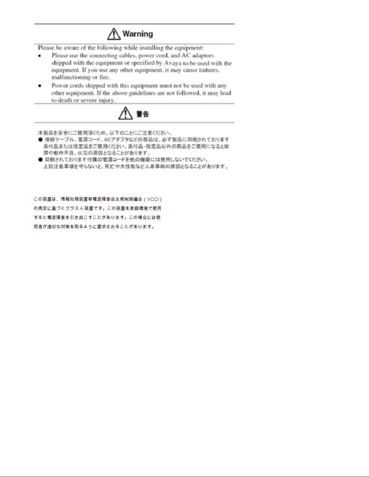
Japan VCCI statement
The following applies to server models 1006r, 1005r, 703t, 201i, and
1002rp:
This is a Class A product based on the standard of the Voluntary Control
Council for Interference by Information Technology Equipment (VCCI).
If this equipment is used in a domestic environment, radio disturbance
may occur, in which case, the user may be required to take corrective
action.
Avaya CallPilot® 1006r Server Hardware Installation December 2010 3

4 Avaya CallPilot® 1006r Server Hardware Installation December 2010

Contents
Chapter 1: Customer service....................................................................................................7
Getting technical documentation.......................................................................................................................7
Getting product training.....................................................................................................................................7
Getting help from a distributor or reseller..........................................................................................................7
Getting technical support from the Avaya Web site..........................................................................................8
Chapter 2: 1006r server description........................................................................................9
In this chapter....................................................................................................................................................9
1006r Server features.......................................................................................................................................9
Introduction.......................................................................................................................................................9
RoHS compliance.............................................................................................................................................9
Server dimensions and weight........................................................................................................................10
Environmental specifications...........................................................................................................................10
Front panel controls and features...................................................................................................................10
Back panel controls and features....................................................................................................................13
PCI riser assembly..........................................................................................................................................13
Valid PCI card configurations..........................................................................................................................16
Introduction.....................................................................................................................................................16
Network connectivity.......................................................................................................................................17
Introduction.....................................................................................................................................................17
Sample network setup: Meridian 1..................................................................................................................17
Sample network setup: Communication Server 1000.....................................................................................18
Switch connectivity..........................................................................................................................................19
CallPilot ELAN subnet and Avaya server subnet setup..................................................................................19
Meridian 1 or Avaya Communication Server 1000 systems............................................................................19
Network requirements.....................................................................................................................................19
Remote access connectivity............................................................................................................................20
Supported peripheral devices.........................................................................................................................20
Introduction.....................................................................................................................................................20
Customer Documentation Map.......................................................................................................................21
Chapter 3: Preparing for installation.....................................................................................25
In this chapter..................................................................................................................................................25
Installation overview........................................................................................................................................25
Introduction.....................................................................................................................................................25
Installation checklist........................................................................................................................................25
Conventions for warnings................................................................................................................................26
Unpacking the 1006r server............................................................................................................................27
Introduction.....................................................................................................................................................27
What is next?..................................................................................................................................................28
Chapter 4: Installing the server and peripheral devices......................................................29
In this chapter..................................................................................................................................................29
Installing the server.........................................................................................................................................29
Introduction.....................................................................................................................................................29
To install the server.........................................................................................................................................29
What is next?..................................................................................................................................................30
Installing a High Availability system................................................................................................................30
Inspecting the modem.....................................................................................................................................31
Avaya CallPilot® 1006r Server Hardware Installation December 2010 5

Introduction.....................................................................................................................................................31
Required equipment........................................................................................................................................31
What is next?..................................................................................................................................................31
Connecting peripherals to the server..............................................................................................................32
Rear panel connectors....................................................................................................................................32
Connecting the server to the Avaya server subnet (optional).........................................................................34
Introduction.....................................................................................................................................................34
What is next?..................................................................................................................................................35
Installing the Avaya software feature dongle..................................................................................................35
Introduction.....................................................................................................................................................35
Chapter 5: Connecting the server to power..........................................................................39
In this chapter..................................................................................................................................................39
Safety precautions..........................................................................................................................................39
Equipment handling guidelines.......................................................................................................................39
Safety information...........................................................................................................................................39
Locating the power supply modules................................................................................................................40
Introduction.....................................................................................................................................................40
About the power supply module......................................................................................................................40
Rack power and grounding.............................................................................................................................40
Connecting the server to power......................................................................................................................41
Before you begin.............................................................................................................................................41
Index.........................................................................................................................................45
6 Avaya CallPilot® 1006r Server Hardware Installation December 2010

Chapter 1: Customer service
Visit the Avaya Web site to access the complete range of services and support that Avaya provides. Go
to www.avaya.com or go to one of the pages listed in the following sections.
Navigation
Getting technical documentation on page 7
•
• Getting product training on page 7
• Getting help from a distributor or reseller on page 7
Getting technical support from the Avaya Web site on page 8
•
Getting technical documentation
To download and print selected technical publications and release notes directly from the
Internet, go to
www.avaya.com/support.
Getting product training
Ongoing product training is available. For more information or to register, you can access the
Web site at www.avaya.com/support. From this Web site, you can locate the Training contacts
link on the left-hand navigation pane.
Getting help from a distributor or reseller
If you purchased a service contract for your Avaya product from a distributor or authorized
reseller, contact the technical support staff for that distributor or reseller for assistance.
Avaya CallPilot® 1006r Server Hardware Installation December 2010 7

Customer service
Getting technical support from the Avaya Web site
The easiest and most effective way to get technical support for Avaya products is from the
Avaya Technical Support Web site at www.avaya.com/support.
8 Avaya CallPilot® 1006r Server Hardware Installation December 2010

Chapter 2: 1006r server description
In this chapter
• 1006r Server features on page 9
• Valid PCI card configurations on page 16
• Network connectivity on page 17
•
Supported peripheral devices on page 20
1006r Server features
Introduction
The 1006r Avaya CallPilot® server is a long life industrial server in a standard rack-mount 2U
form factor. It utilizes dual Xeon technology and proven, reliable SAS hard-drive technology.
RoHS compliance
The 1006r server meets the requirements of the Restriction of Hazardous Substances Directive
2002/95/EC, applicable in countries affected by the EUED (European Union Environmental
Directives). RoHS requirements impose restrictions on the type and quantity of materials used
in the manufacturing and construction of Electronic and Electrical Equipment (EEE).
To comply with the RoHS directive, some of the part numbers now contain an E5 or E6 suffix.
For example, part number NTRH2014 is now NTRH2014E6. The part numbers in this guide
do not contain the suffix.
Avaya CallPilot® 1006r Server Hardware Installation December 2010 9
1006r server description
Server dimensions and weight
Height 87.3 mm (3.44 in.)
Width 430 mm (16.93 in.)
Depth (distance from front to back) 704.8 mm (27.75 in.)
Weight of fully loaded system 29.5 kg (65 lb)
Environmental specifications
Environmental condition Specification
Operating temperature 10°C to 35°C (50°F to 95°F)
Maximum rate of change must not exceed
10°C (50°F) per hour.
Non operating (storage) temperature -40°C to +70°C (-40°F to +158°F)
Non operating humidity 90% relative humidity (non-condensing) at
28°C (82.4 °F)
Altitude < 1 829 m (6 000 ft)
Electrostatic discharge <= 15 kV
Acoustic noise Sound power: 7.0 BA in an idle state
Handling drop (storage) 24 in free-fall (when packaged)
Handling drop (operating) 2g peak, 11 msec, half sine
Front clearance 50.8 mm (2 in.)
Side clearance 25 mm (1 in.)
Rear clearance 92 mm (3.6 in.)
Front panel controls and features
The following diagrams show the front view of the 1006r server chassis. Visible from the front
are the hard drives, optical drive, and system control panel.
10 Avaya CallPilot® 1006r Server Hardware Installation December 2010
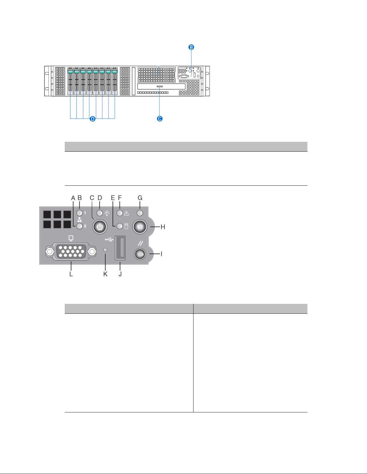
Figure 1: Front panel controls
Label Control or feature
B System Control Panel (see figure below for details)
C Slimline Optical Drive Bay
D 2.5-inch Hard Drive Bays (two installed)
Front panel controls and features
Figure 2: System control panel
Label Control or feature Function
A NIC 2 Activity LED Continuous green light indicates a link
B NIC 1 Activity LED
C Power/Sleep button Toggles the system power on/off. This
D Power/Sleep LED Continuous green light indicates the
Avaya CallPilot® 1006r Server Hardware Installation December 2010 11
between the system and the network to
which it is connected.
Blinking green light indicates network
activity.
button also functions as a sleep button if
enabled by an ACPI-compliant operating
system.
system has power applied to it or the
system is in ACPI S0 state.
1006r server description
Label Control or feature Function
E Hard disk drive activity LED Random blinking green light indicates
F System status LED Solid green indicates normal operation.
G System identification LED Solid blue indicates system identification
Blinking green indicates the system is in
sleep or ACPI S1 state.
No light indicates the power is off or the
system is in ACPI S4 or S5 state.
hard disk drive activity.
No light indicates no hard disk drive
activity.
Blinking green indicates degraded
performance.
Solid amber indicates a critical or nonrecoverable condition.
Blinking amber indicates a non-critical
condition.
No light indicates POST is running or the
system is off.
is active.
No light indicates system identification is
not activated.
H System identification button Toggles the front panel ID LED and the
server board ID LED on/off. The server
board ID LED is visible through the rear of
the system and allows for server
identification and location when working
behind a rack of servers.
I Reset button Reboots and initializes the system.
J USB 2.0 Port Connector to attach a USB component to
the front of the system.
K NMI button When the NMI button is pressed with a
paper clip or pin, the server is placed in a
halt state for diagnostic purposes and
allows the issuance of a non-maskable
interrupt. After issuing the interrupt, a
memory download can be performed to
determine the cause of the problem.
L Front Video port Connector to attach a video monitor to the
front of the system. The front and rear
video ports cannot be used at the same
time however the front takes priority if both
ports are used.
12 Avaya CallPilot® 1006r Server Hardware Installation December 2010

Back panel controls and features
The following diagram shows the back panel controls and features. On the right are the AC
power supply banks. The PCI card brackets are in the middle of the back panel while the
connectors and ports are along the bottom and left side.
Figure 3: Back panel controls and features
Back panel controls and features
Label Control or feature Label Control or feature
A RJ-45 Serial A Connector I Not connected
B Rear Video J HB2
C Dual USB port K Power Receptacles
D Dual USB port L MPB96-1 DS30-3
E ELAN M MPB96-1 DS30-2
F CLAN N MPB96-1 DS30-1
G HB1
H Mirror
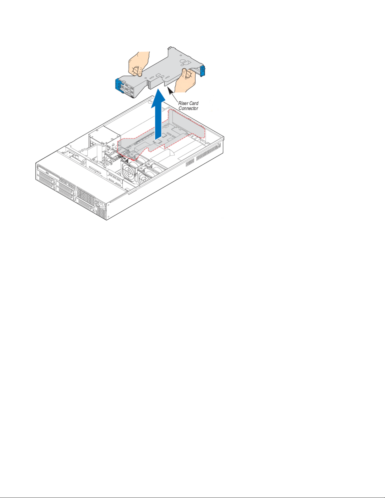
PCI riser assembly
The PCI riser assembly holds the MPB96 PCI add-in cards. For more information about your
configuration, see Valid PCI card configurations on page 16. The following diagram shows
the PCI riser held above the server.
Avaya CallPilot® 1006r Server Hardware Installation December 2010 13
1006r server description
Figure 4: PCI riser card
The following picture shows the PCI riser assembly when removed from the 1006r chassis.
The PCI riser assembly is shown turned over with full-size cards installed.
14 Avaya CallPilot® 1006r Server Hardware Installation December 2010
 Loading...