

Page 1

Avaya CallPilot® 1005r Server Hardware
Installation
NN44200-308, 01.09
December 2010
5.0
Page 2

© 2010 Avaya Inc.
All Rights Reserved.
Notice
While reasonable efforts have been made to ensure that the
information in this document is complete and accurate at the time of
printing, Avaya assumes no liability for any errors. Avaya reserves the
right to make changes and corrections to the information in this
document without the obligation to notify any person or organization of
such changes.
Documentation disclaimer
“Documentation” means information published by Avaya in varying
mediums which may include product information, operating instructions
and performance specifications that Avaya generally makes available
to users of its products. Documentation does not include marketing
materials. Avaya shall not be responsible for any modifications,
additions, or deletions to the original published version of
documentation unless such modifications, additions, or deletions were
performed by Avaya. End User agrees to indemnify and hold harmless
Avaya, Avaya's agents, servants and employees against all claims,
lawsuits, demands and judgments arising out of, or in connection with,
subsequent modifications, additions or deletions to this documentation,
to the extent made by End User.
Link disclaimer
Avaya is not responsible for the contents or reliability of any linked Web
sites referenced within this site or documentation provided by Avaya.
Avaya is not responsible for the accuracy of any information, statement
or content provided on these sites and does not necessarily endorse
the products, services, or information described or offered within them.
Avaya does not guarantee that these links will work all the time and has
no control over the availability of the linked pages.
Warranty
Avaya provides a limited warranty on its Hardware and Software
(“Product(s)”). Refer to your sales agreement to establish the terms of
the limited warranty. In addition, Avaya’s standard warranty language,
as well as information regarding support for this Product while under
warranty is available to Avaya customers and other parties through the
Avaya Support Web site:
you acquired the Product(s) from an authorized Avaya reseller outside
of the United States and Canada, the warranty is provided to you by
said Avaya reseller and not by Avaya.
Licenses
THE SOFTWARE LICENSE TERMS AVAILABLE ON THE AVAYA
WEBSITE,
APPLICABLE TO ANYONE WHO DOWNLOADS, USES AND/OR
INSTALLS AVAYA SOFTWARE, PURCHASED FROM AVAYA INC.,
ANY AVAYA AFFILIATE, OR AN AUTHORIZED AVAYA RESELLER
(AS APPLICABLE) UNDER A COMMERCIAL AGREEMENT WITH
AVAYA OR AN AUTHORIZED AVAYA RESELLER. UNLESS
OTHERWISE AGREED TO BY AVAYA IN WRITING, AVAYA DOES
NOT EXTEND THIS LICENSE IF THE SOFTWARE WAS OBTAINED
FROM ANYONE OTHER THAN AVAYA, AN AVAYA AFFILIATE OR AN
AVAYA AUTHORIZED RESELLER; AVAYA RESERVES THE RIGHT
TO TAKE LEGAL ACTION AGAINST YOU AND ANYONE ELSE
USING OR SELLING THE SOFTWARE WITHOUT A LICENSE. BY
INSTALLING, DOWNLOADING OR USING THE SOFTWARE, OR
AUTHORIZING OTHERS TO DO SO, YOU, ON BEHALF OF
YOURSELF AND THE ENTITY FOR WHOM YOU ARE INSTALLING,
DOWNLOADING OR USING THE SOFTWARE (HEREINAFTER
REFERRED TO INTERCHANGEABLY AS “YOU” AND “END USER”),
AGREE TO THESE TERMS AND CONDITIONS AND CREATE A
BINDING CONTRACT BETWEEN YOU AND AVAYA INC. OR THE
APPLICABLE AVAYA AFFILIATE (“AVAYA”).
HTTP://SUPPORT.AVAYA.COM/LICENSEINFO/ ARE
http://support.avaya.com. Please note that if
Copyright
Except where expressly stated otherwise, no use should be made of
materials on this site, the Documentation, Software, or Hardware
provided by Avaya. All content on this site, the documentation and the
Product provided by Avaya including the selection, arrangement and
design of the content is owned either by Avaya or its licensors and is
protected by copyright and other intellectual property laws including the
sui generis rights relating to the protection of databases. You may not
modify, copy, reproduce, republish, upload, post, transmit or distribute
in any way any content, in whole or in part, including any code and
software unless expressly authorized by Avaya. Unauthorized
reproduction, transmission, dissemination, storage, and or use without
the express written consent of Avaya can be a criminal, as well as a
civil offense under the applicable law.
Third-party components
Certain software programs or portions thereof included in the Product
may contain software distributed under third party agreements (“Third
Party Components”), which may contain terms that expand or limit
rights to use certain portions of the Product (“Third Party Terms”).
Information regarding distributed Linux OS source code (for those
Products that have distributed the Linux OS source code), and
identifying the copyright holders of the Third Party Components and the
Third Party Terms that apply to them is available on the Avaya Support
Web site:
Trademarks
The trademarks, logos and service marks (“Marks”) displayed in this
site, the Documentation and Product(s) provided by Avaya are the
registered or unregistered Marks of Avaya, its affiliates, or other third
parties. Users are not permitted to use such Marks without prior written
consent from Avaya or such third party which may own the Mark.
Nothing contained in this site, the Documentation and Product(s)
should be construed as granting, by implication, estoppel, or otherwise,
any license or right in and to the Marks without the express written
permission of Avaya or the applicable third party.
Avaya is a registered trademark of Avaya Inc.
All non-Avaya trademarks are the property of their respective owners,
and “Linux” is a registered trademark of Linus Torvalds.
Downloading Documentation
For the most current versions of Documentation, see the Avaya
Support Web site:
Contact Avaya Support
Avaya provides a telephone number for you to use to report problems
or to ask questions about your Product. The support telephone number
is 1-800-242-2121 in the United States. For additional support
telephone numbers, see the Avaya Web site:
Japan Denan statement
The following applies to server models 1006r, 1005r, 703t, and 1002rp:
http://support.avaya.com/Copyright.
http://support.avaya.com.
http://support.avaya.com.
2 Avaya CallPilot® 1005r Server Hardware Installation December 2010
Page 3
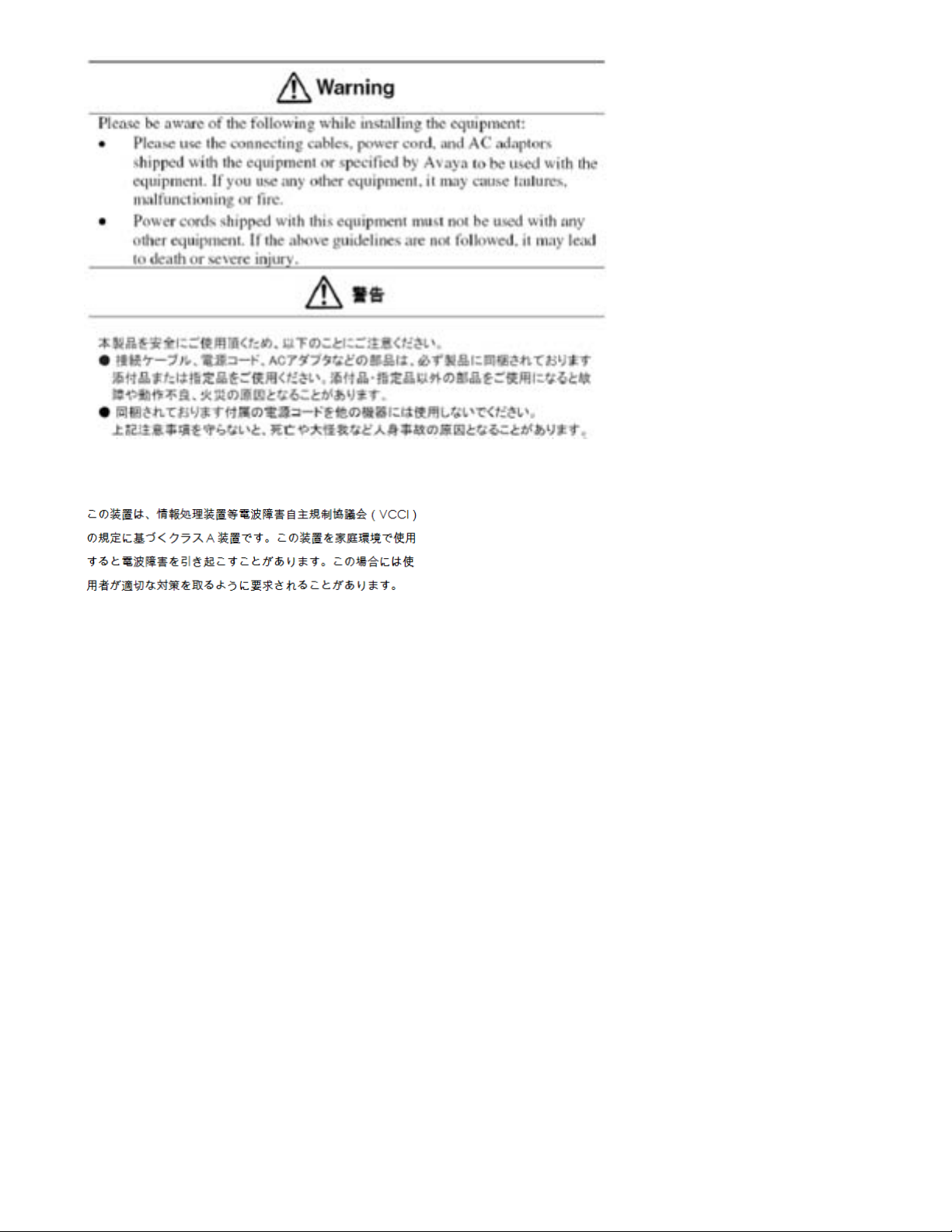
Japan VCCI statement
The following applies to server models 1006r, 1005r, 703t, 201i, and
1002rp:
This is a Class A product based on the standard of the Voluntary Control
Council for Interference by Information Technology Equipment (VCCI).
If this equipment is used in a domestic environment, radio disturbance
may occur, in which case, the user may be required to take corrective
action.
Avaya CallPilot® 1005r Server Hardware Installation December 2010 3
Page 4

4 Avaya CallPilot® 1005r Server Hardware Installation December 2010
Page 5

Contents
Chapter 1: Customer service....................................................................................................7
Getting technical documentation.......................................................................................................................7
Getting product training.....................................................................................................................................7
Getting help from a distributor or reseller..........................................................................................................7
Getting technical support from the Avaya Web site..........................................................................................8
Chapter 2: 1005r server description........................................................................................9
In this chapter....................................................................................................................................................9
1005r Server features.......................................................................................................................................9
Introduction.......................................................................................................................................................9
RoHS compliance.............................................................................................................................................9
Server dimensions and weight........................................................................................................................10
Environmental specifications...........................................................................................................................10
Front panel controls and features...................................................................................................................10
Back panel controls and features....................................................................................................................12
PCI riser assembly..........................................................................................................................................13
Valid PCI card configurations..........................................................................................................................15
Introduction.....................................................................................................................................................15
Network connectivity.......................................................................................................................................16
Introduction.....................................................................................................................................................16
Sample network setup: Meridian 1..................................................................................................................17
Sample network setup: Communication Server 1000.....................................................................................17
Switch connectivity..........................................................................................................................................18
CallPilot ELAN subnet and Avaya server subnet setup..................................................................................18
Meridian 1 or Avaya Communication Server 1000 systems............................................................................19
Network requirements.....................................................................................................................................19
Remote access connectivity............................................................................................................................19
Supported peripheral devices.........................................................................................................................20
Introduction.....................................................................................................................................................20
Customer Documentation Map.......................................................................................................................20
Chapter 3: Preparing for installation.....................................................................................25
In this chapter..................................................................................................................................................25
Installation overview........................................................................................................................................25
Introduction.....................................................................................................................................................25
Installation checklist........................................................................................................................................25
Conventions for warnings................................................................................................................................27
Unpacking the 1005r server............................................................................................................................28
Introduction.....................................................................................................................................................28
What is next?..................................................................................................................................................28
Removing the front bezel................................................................................................................................29
Introduction.....................................................................................................................................................29
What is next?..................................................................................................................................................30
Chapter 4: Installing the server and peripheral devices......................................................31
In this chapter..................................................................................................................................................31
Installing the server.........................................................................................................................................31
Introduction.....................................................................................................................................................31
To install the server.........................................................................................................................................31
Avaya CallPilot® 1005r Server Hardware Installation December 2010 5
Page 6

What is next?..................................................................................................................................................32
Installing a High Availability system................................................................................................................32
Inspecting the modem.....................................................................................................................................33
Introduction.....................................................................................................................................................33
Required equipment........................................................................................................................................33
What is next?..................................................................................................................................................33
Connecting peripherals to the server..............................................................................................................34
Rear panel connectors....................................................................................................................................34
What is next?..................................................................................................................................................36
Connecting the server to the ELAN subnet.....................................................................................................37
Introduction.....................................................................................................................................................37
What is next?..................................................................................................................................................38
Connecting the server to the Avaya server subnet (optional).........................................................................38
Introduction.....................................................................................................................................................38
What is next?..................................................................................................................................................39
Installing the Avaya software feature dongle..................................................................................................39
Introduction.....................................................................................................................................................39
Chapter 5: Connecting the server to power..........................................................................43
In this chapter..................................................................................................................................................43
Safety precautions..........................................................................................................................................43
Equipment handling guidelines.......................................................................................................................43
Safety information...........................................................................................................................................43
Locating the power supply modules................................................................................................................44
Introduction.....................................................................................................................................................44
About the power supply module......................................................................................................................44
Rack power and grounding.............................................................................................................................44
Connecting the server to power......................................................................................................................45
Before you begin.............................................................................................................................................45
Chapter 6: EMC emission level protection for the 1005r Server.........................................49
Index.........................................................................................................................................51
6 Avaya CallPilot® 1005r Server Hardware Installation December 2010
Page 7

Chapter 1: Customer service
Visit the Avaya Web site to access the complete range of services and support that Avaya provides. Go
to www.avaya.com or go to one of the pages listed in the following sections.
Navigation
Getting technical documentation on page 7
•
• Getting product training on page 7
• Getting help from a distributor or reseller on page 7
Getting technical support from the Avaya Web site on page 8
•
Getting technical documentation
To download and print selected technical publications and release notes directly from the
Internet, go to
www.avaya.com/support.
Getting product training
Ongoing product training is available. For more information or to register, you can access the
Web site at www.avaya.com/support. From this Web site, you can locate the Training contacts
link on the left-hand navigation pane.
Getting help from a distributor or reseller
If you purchased a service contract for your Avaya product from a distributor or authorized
reseller, contact the technical support staff for that distributor or reseller for assistance.
Avaya CallPilot® 1005r Server Hardware Installation December 2010 7
Page 8

Customer service
Getting technical support from the Avaya Web site
The easiest and most effective way to get technical support for Avaya products is from the
Avaya Technical Support Web site at www.avaya.com/support.
8 Avaya CallPilot® 1005r Server Hardware Installation December 2010
Page 9
Chapter 2: 1005r server description
In this chapter
1005r Server features on page 9
Valid PCI card configurations on page 15
Network connectivity on page 16
Supported peripheral devices on page 20
1005r Server features
Introduction
The 1005r Avaya CallPilot® server is a long life industrial server in a standard rack-mount 2U
form factor. It utilizes dual Xeon technology and proven, reliable SCSI hard-drive technology.
This section provides a general overview of the 1005r server features.
RoHS compliance
The 1005r server meets the requirements of the Restriction of Hazardous Substances Directive
2002/95/EC, applicable in countries affected by the EUED (European Union Environmental
Directives). RoHS requirements impose restrictions on the type and quantity of materials used
in the manufacturing and construction of Electronic and Electrical Equipment (EEE).
To comply with the RoHS directive, some of the part numbers now contain an E5 or E6 suffix.
For example, part number NTRH2014 is now NTRH2014E6. The part numbers in this guide
do not contain the suffix.
Avaya CallPilot® 1005r Server Hardware Installation December 2010 9
Page 10
1005r server description
Server dimensions and weight
Height 87.6 mm (3.45 in.)
Width 435.3 mm (17.4 in.)
Depth (distance from front to back) 508 mm (20 in.)
Weight of fully loaded system 20 kg (44 lb)
Environmental specifications
Environmental condition Specification
Operating temperature 5°C to 35°C (41°F to 95°F)
Maximum rate of change must not exceed
10°C (50°F) per hour.
Non operating (storage) temperature -40°C to +70°C (-40°F to +158°F)
Non operating humidity 95% @ 23 to 40°C
Altitude < 1 829 m (6 000 ft)
Electrostatic discharge <= 15 kV
Acoustic noise < 55 dBA
Handling drop (storage) 18 in free-fall (when packaged)
Handling drop 2g 11 mS
Front clearance 50.8 mm (2 in.)
Side clearance 25 mm (1 in.)
Rear clearance 92 mm (3.6 in.)
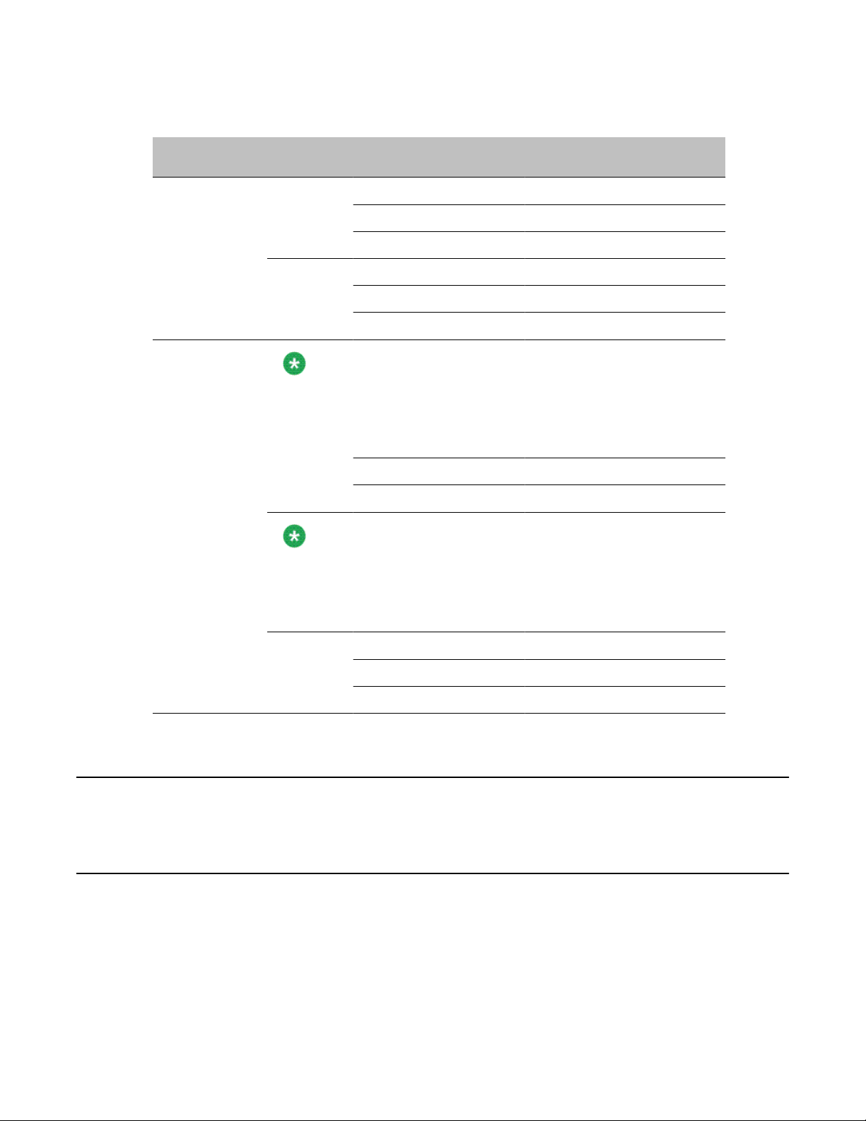
Front panel controls and features
The following diagram shows the front view of the 1005r server chassis with the bezel cover
removed. When the bezel cover is on, only the DVD and USB connections, controls, alarm
LEDs, and status LEDs are visible. With the bezel cover removed, both hard drives, the
10 Avaya CallPilot® 1005r Server Hardware Installation December 2010
Page 11
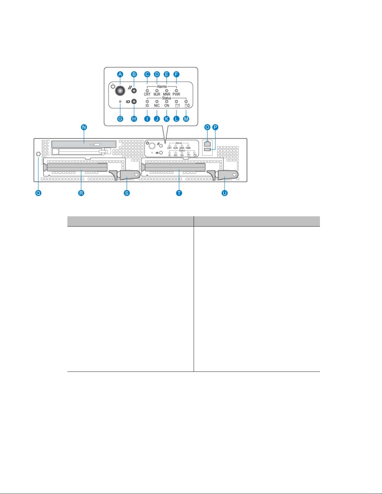
peripheral DVD/CD/CDRW drive, the anti-static connection, and the front serial port are
accessible.
Figure 1: Front panel controls
Front panel controls and features
Label Control or feature Label Control or feature
A Power switch L HDD1 activity
B Reset switch M HDD0 activity
C Critical alarm LED N DVD/CD/CDRW LED and eject
button
D Major alarm LED O Front serial port
E Minor Alarm LED P USB 2
F Power Alarm LED Q Electrostatic Discharge (ESD)
connection
G NMI switch (not used) R Hard drive 1 pull handle
H ID switch S Hard drive 1 release lever
I ID LED T Hard drive 0 pull handle
J NIC activity LED U Hard drive 0 release lever
K Status LED
Avaya CallPilot® 1005r Server Hardware Installation December 2010 11
Page 12
1005r server description
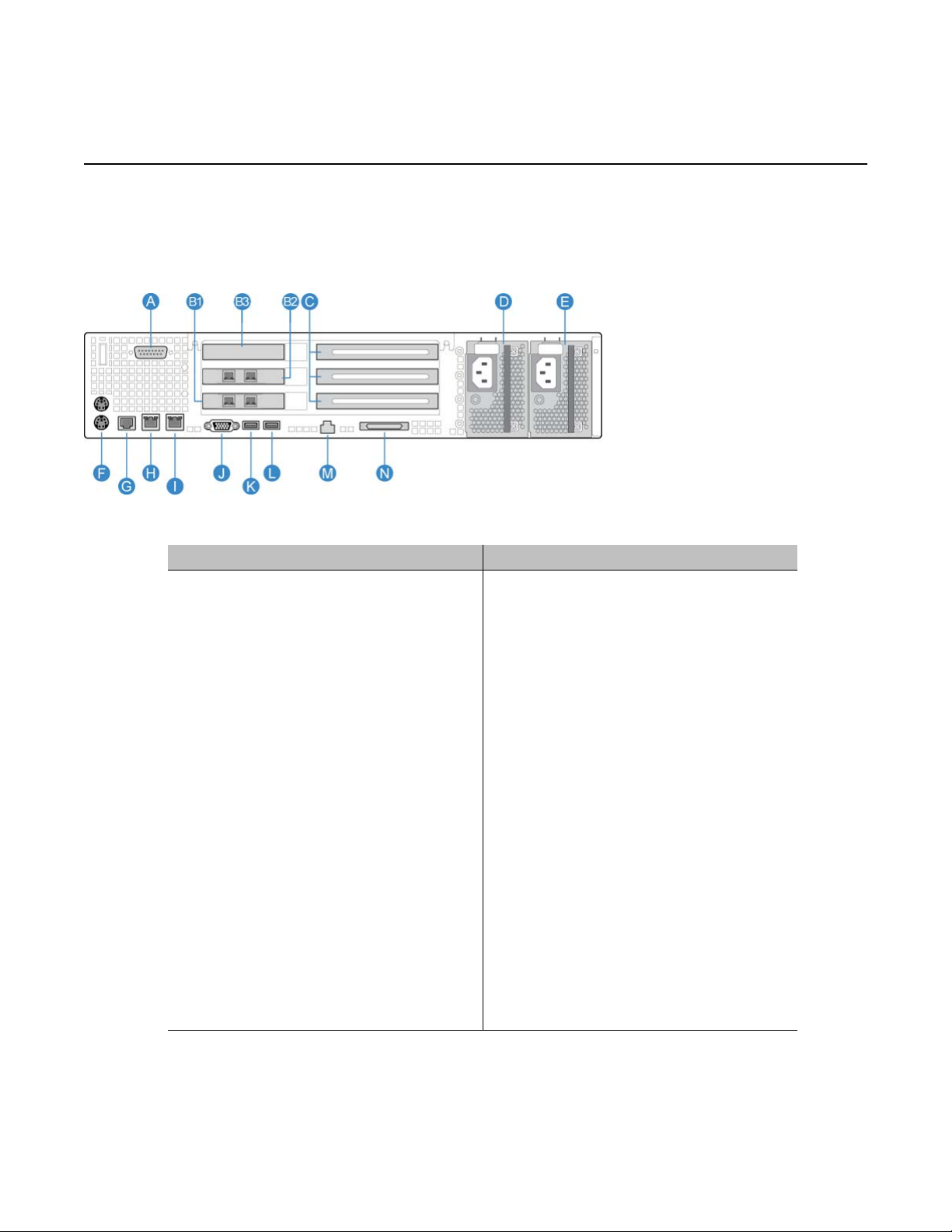
Back panel controls and features
The following diagram shows the back panel controls and features. On the right are the AC
power supply banks. The PCI card brackets are in the middle of the back panel while the
connectors and ports are along the bottom and left side.
Figure 2: Back panel controls and features
Label Control or feature Label Control or feature
A DB15 Telco alarm connector (not
used)
B1 PCI card #3 dual NIC for High
Availability (HA) configuration. For
more information about HA, see
High Availability: Installation and
Configuration (NN44200-311).
B2 PCI card #2 dual NIC for HA
configuration. For more information
about HA, see High Availability:
Installation and Configuration
(NN44200-311).
B3 RAID J Video connector
C PCI full-size card brackets.
Numbered (1, 2, 3) from top to
bottom.
D Power Supply 1 L USB 0
E Power Supply 2 M Server management LAN port
G Rear connection to Comm 2 serial
port
H RJ45 NIC 1 connector
I RJ45 NIC 2 connector
K USB 1
F PS/2 mouse and keyboard
connectors
12 Avaya CallPilot® 1005r Server Hardware Installation December 2010
N External SCSI tape drive
Page 13
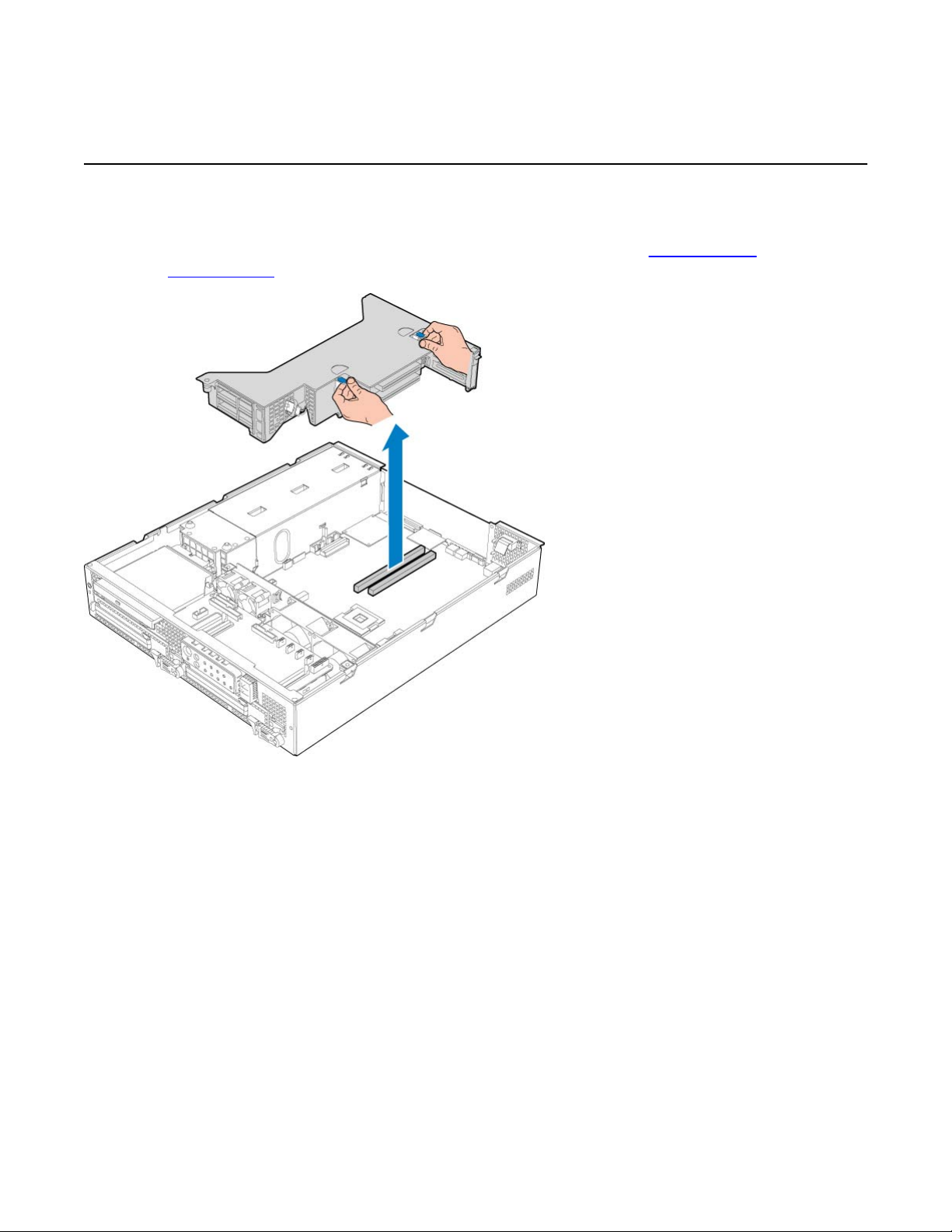
PCI riser assembly
The PCI riser assembly holds the PCI add-in cards; MPB96, RAID and dual Network Interface
Card (NIC). For more information about your configuration, see Valid PCI card
configurations on page 15. The following diagram shows the PCI riser held above the server.
PCI riser assembly
Figure 3: PCI riser card
The following picture shows the PCI riser assembly when removed from the 1005r chassis.
The PCI riser assembly is shown turned over with low-profile and full-size cards installed.
Avaya CallPilot® 1005r Server Hardware Installation December 2010 13
Page 14
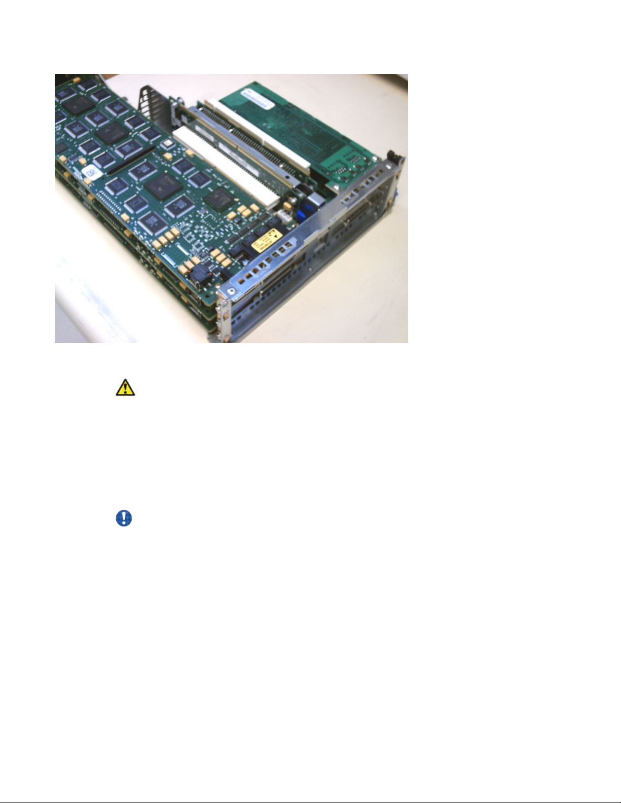
1005r server description
Figure 4: PCI riser card (turned over)
Caution:
Risk of physical equipment damage
Remove the 1005r from the rack, and place it on a solid surface when replacing or adding
cards. The PCI riser assembly requires considerable force when inserting it into the
connector, and physical damage can result if the assembly is not properly aligned.
When you place the server on a solid surface such as a workbench, you have a better view of
the card alignment, and you can exert the necessary force when inserting the assembly into
the connector.
Important:
If The PCI riser assembly must be fully seated to avoid server malfunction.
14 Avaya CallPilot® 1005r Server Hardware Installation December 2010
Page 15
Valid PCI card configurations
Introduction
There are six PCI card slots; three low-profile and three full-size. Valid configurations of lowprofile and full-size cards are shown in the table Table 1: 1005r PCI card slot configurations on
page 16.
Note:
Your server configuration depends on what was ordered from Avaya. Therefore, your server
may not have all of the slots populated.
When looking at the server from the rear (see Back panel controls and features on page 12),
both full-size and low-profile cards are numbered from the top down.
Valid PCI card configurations
Note:
There are two MPB96 board versions; the NTRH40AA, and NTRH40CA. The following table
compares the two boards.
Version Description
NTRH40AA Has a single DB-44 connector on its faceplate
Connects to the CS 1000 or Meridian 1 with an NTRH2014 DS30X
cable
NTRH40CA Has three RJ-45 connectors on its faceplate
Connects to the Avaya CS 1000 or Meridian 1 with three standard
RJ-45 connectorized Ethernet cables
For more information about these cables and connecting the
NTRH40CA MPB96 board to MGate cards, see Communication
Server and CallPilot Server Configuration(NN44200-312) or
Meridian 1 and CallPilot Server Configuration(NN44200-302).
Important:
If you have an NTRH40AA MPB96 board, you must connect the DS30X-1 cable to an MGate
card to receive the clock source for the MPB96 board. Failure to connect the DS30X-1 cable
to an MGate card can result in noise interference on the remaining voice channels. This
restriction does not apply to the NTRH40CA MPB96 board, as it can receive clock source
from any of the three DS30 ports.
Avaya CallPilot® 1005r Server Hardware Installation December 2010 15
Page 16
1005r server description
Table 1: 1005r PCI card slot configurations
Configuration Card slot
type
Single MPB96 Full size FS_PCI-1 top MPB96 MGate 1, 2, 3
Low profile LP_PCI-1 top RAID
Note:
When cabling to MGate cards, the RJ-45 connectors are numbered
from 1 to 3 on the NTRH40CA MPB96 board starting from the right
side of the back panel (next to the power supplies).
Three MPB96
(High Capacity)
Full size FS_PCI-1 top MPB96 MGate 1, 2, 3
Note:
3 Mgate cards connect to 1 MPB96
When cabling to MGate cards, the RJ-45 connectors are numbered
from 1 to 3 on the top NTRH40CA MPB96 board and from 4 to 6 on
the middle NTRH40CA MPB96 board starting from the right side of the
back panel (next to the power supplies)
Slot
number
FS_PCI-2 middle Not used
FS_PCI-3 bottom Not used
LP_PCI-2 middle Dual NIC
LP_PCI-3 bottom Dual NIC
FS_PCI-2 middle MPB96 MGate 4, 5, 6
FS_PCI-3 bottom MPB96
Position Card type Meridian 1*/
Avaya CS* 1000
Low profile LP_PCI-1 top RAID
Network connectivity
Introduction
This section describes how the 1005r server can be integrated into your network. The
integration depends on the type of switch you are using.
LP_PCI-2 middle Dual NIC
LP_PCI-3 bottom Dual NIC
16 Avaya CallPilot® 1005r Server Hardware Installation December 2010
Page 17
Important:
To secure the Avaya CallPilot server from unauthorized access, ensure that the CallPilot
network is inside your organization's firewall.
Sample network setup: Meridian 1
The following diagram shows a CallPilot server sample network setup with a Meridian 1 switch.
The Meridian 1 switch can be one of the following:
• Option 11C or Option 11C Mini
• Option 51C
• Option 61C
• Options 81 and 81C
Sample network setup: Meridian 1
Sample network setup: Communication Server 1000
The following diagram shows a CallPilot server network setup with a Communication Server
1000 (CS 1000) system.
Avaya CallPilot® 1005r Server Hardware Installation December 2010 17
Page 18

1005r server description
In the previous illustration, the telephony LAN (TLAN subnet) provides IP connectivity between
the CS 1000 system and the i2004 Internet phonesets. The connection between the call server
and media gateway can be point-to-point (or through the LAN), if the system is installed in a
distributed data network.
For information about the CS 1000 system and i2004 Internet phoneset bandwidth and network
requirements, refer to the Communication Server for Enterprise 1000 Planning and Installation
Guide (553-3023-210).
Switch connectivity
For more details about how the 1005r server and switch connection is established, refer to the
Installation and Configuration Task List (NN44200-306).
CallPilot ELAN subnet and Avaya server subnet setup
The 1005r server provides 10/100/1000Base-T Ethernet connectivity through NICs installed
in the server. The function of the NIC varies based on switch connectivity, as follows:
18 Avaya CallPilot® 1005r Server Hardware Installation December 2010
Page 19

Meridian 1 or Avaya Communication Server 1000 systems
Meridian 1 or Avaya Communication Server 1000 systems
• One NIC provides connectivity to the ELAN subnet. Connect the NIC labeled NIC2NickP on the back of the server to the ELAN subnet.
For information about the purpose and requirements of the ELAN subnet, see the
Planning and Engineering Guide (NN44200-200).
• The second NIC, labeled NIC1-NickP can be connected to the Avaya server subnet.
This optional NIC is required only for Meridian 1 or Avaya Communication Server 1000
systems that require a Avaya server subnet connection (in addition to the ELAN subnet
connection). The Avaya server subnet provides data connectivity between desktop and
Web messaging clients, Web-enabled administrative PCs, and the CallPilot server.
Network requirements
Appropriate networking equipment must be available for both the Avaya server subnet and
ELAN subnet.
The Avaya server subnet and ELAN subnet must be properly configured for correct CallPilot
operation. To ensure correct configuration, Avaya recommends that you consult a network
specialist.
Remote access connectivity
Use one of the USB connectors on the rear of the 1005r server to connect to an external plugand-play modem. The modem is used for remote administration and technical support.
RRAS is used to establish the remote access connection to the server. Use either RDC or
pcAnywhere to communicate with the CallPilot server.
Avaya CallPilot® 1005r Server Hardware Installation December 2010 19
Page 20

1005r server description
Supported peripheral devices
Introduction
This section identifies external devices that are supported by the 1005r server.
Device Description
Modem Use a 56-Kb/s external modem to provide remote access to the
1005r server. The modem connects to one of the USB
connectors on the rear of the server. You cannot use a serial
port modem.
Ethernet switch or hub A 10Base-T Ethernet switch or hub provides the ELAN subnet
connection between the 1005r server and the Meridian 1 switch
or CS 1000 system. The customer can supply an Ethernet hub
or switch from third-party vendors or from Avaya.
Since the Ethernet switch or hub is an external device, it
requires an AC power source.
Important:
To comply with EMC radiation requirements, a Class A
Ethernet hub or switch must be located 10 m (33 ft) away
from the 1005r server. Shielded Ethernet cables must be
used.
Monitor, keyboard, and
mouse
Tape drive
• VGA Monitor with Male DB-15 connector (customer supplied)
Since the monitor is an external device, it requires its own AC
power source.
• Keyboard: (customer supplied)
• Mouse: (customer supplied)
Use an external SCSI tape drive to back up your system. The
Tandberg SLR 75 can be ordered with your system.
Customer Documentation Map
The following diagram shows the overall organization and content of the CallPilot
documentation suite.
20 Avaya CallPilot® 1005r Server Hardware Installation December 2010
Page 21

Table 2: CallPilot Customer Documentation Map
Fundamentals
Avaya CallPilot® Fundamentals Guide (NN44200-100)
Avaya CallPilot® Library Listing (NN44200-117)
Planning and Engineering
Avaya CallPilot® Planning and Engineering Guide (NN44200-200)
Avaya CallPilot® Network Planning Guide (NN44200-201)
Avaya Communication Server 1000 Converging the Data Network with VoIP
Fundamentals (NN43001-260)
Solution Integration Guide for Avaya Communication Server 1000/CallPilot®/NES
Contact Center/Telephony Manager (NN49000-300)
Installation and Configuration
Avaya CallPilot® Upgrade and Platform Migration Guide (NN44200-400)
Avaya CallPilot® High Availability: Installation and Configuration (NN44200-311)
Customer Documentation Map
Avaya CallPilot® Geographic Redundancy Application Guide (NN44200-322)
Avaya CallPilot® Installation and Configuration Task List Guide (NN44200-306)
Avaya CallPilot® Quickstart Guide (NN44200-313)
Avaya CallPilot® Installer Roadmap (NN44200-314)
Server Installation Guides
Avaya CallPilot® 201i Server Hardware Installation Guide (NN44200-301)
Avaya CallPilot® 202i Server Hardware Installation Guide (NN44200-317)
Avaya CallPilot® 202i Installer Roadmap (NN44200-319)
Avaya CallPilot® 703t Server Hardware Installation Guide (NN44200-304)
Avaya CallPilot® 1002rp Server Hardware Installation Guide
(NN44200-300)
Avaya CallPilot® 1002rp System Evaluation (NN44200-318)
Avaya CallPilot® 1005r Server Hardware Installation Guide
(NN44200-308)
Avaya CallPilot® 1005r System Evaluation (NN44200-316)
Avaya CallPilot® 1006r Server Hardware Installation Guide
(NN44200-320)
Avaya CallPilot® 600r Server Hardware Installation Guide
(NN44200-307)
Avaya CallPilot® 600r System Evaluation (NN44200-315)
Avaya CallPilot® 1005r Server Hardware Installation December 2010 21
Page 22

1005r server description
Configuration and Testing Guides
Unified Messaging Software Installation
Administration
Avaya CallPilot® Administrator Guide (NN44200-601)
Avaya CallPilot® Software Administration and Maintenance Guide (NN44200-600)
Avaya Meridian Mail to Avaya CallPilot® Migration Utility Guide (NN44200-502)
Avaya CallPilot® Application Builder Guide (NN44200-102)
Avaya Meridian 1 and Avaya CallPilot® Server Configuration Guide
(NN44200-302)
Avaya T1/SMDI and Avaya CallPilot® Server Configuration Guide
(NN44200-303)
Avaya Communication Server 1000 System and Avaya CallPilot® Server
Configuration Guide (NN44200-312)
Avaya CallPilot® Desktop Messaging and My CallPilot Installation and
Administration Guide (NN44200-305)
Avaya CallPilot® Reporter Guide (NN44200-603)
Maintenance
Avaya CallPilot® Troubleshooting Reference Guide (NN44200-700)
Avaya CallPilot® Preventative Maintenance Guide (NN44200-505)
Server Maintenance and Diagnostics
Avaya CallPilot® 201i Server Maintenance and Diagnostics Guide
(NN44200-705)
Avaya CallPilot® 202i Server Maintenance and Diagnostics Guide
(NN44200-708)
Avaya CallPilot® 703t Server Maintenance and Diagnostics Guide
(NN44200-702)
Avaya CallPilot® 1002rp Server Maintenance and Diagnostics Guide
(NN44200-701)
Avaya CallPilot® 1005r Server Maintenance and Diagnostics Guide
(NN44200-704)
Avaya CallPilot® 1006r Server Maintenance and Diagnostics Guide
(NN44200-709)
Avaya CallPilot® 600r Server Maintenance and Diagnostics Guide
(NN44200-703)
Avaya NES Contact Center Manager Communication Server 1000/
Meridian 1 & Voice Processing Guide (297-2183-931)
End User Information
22 Avaya CallPilot® 1005r Server Hardware Installation December 2010
Page 23

End User Cards
Avaya CallPilot® Unified Messaging Quick Reference Card
(NN44200-111)
Avaya CallPilot® Unified Messaging Wallet Card (NN44200-112)
Avaya CallPilot® A-Style Command Comparison Card (NN44200-113)
Avaya CallPilot® S-Style Command Comparison Card (NN44200-114)
Avaya CallPilot® Menu Interface Quick Reference Card (NN44200-115)
Avaya CallPilot® Alternate Command Interface Quick Reference Card
(NN44200-116)
Avaya CallPilot® Multimedia Messaging User Guide (NN44200-106)
Avaya CallPilot® Speech Activated Messaging User Guide
(NN44200-107)
Avaya CallPilot® Desktop Messaging User Guide for Microsoft Outlook
(NN44200-103)
Avaya CallPilot® Desktop Messaging User Guide for Lotus Notes
(NN44200-104)
Customer Documentation Map
Avaya CallPilot® Desktop Messaging User Guide for Novell Groupwise
(NN44200-105)
Avaya CallPilot® Desktop Messaging User Guide for Internet Clients
(NN44200-108)
Avaya CallPilot® Desktop Messaging User Guide for My CallPilot
(NN44200-109)
Avaya CallPilot® Voice Forms Transcriber User Guide (NN44200-110)
The Map was created to facilitate navigation through the suite by showing the main task groups
and the documents contained in each category. It appears near the beginning of each guide,
showing that guide's location within the suite.
Avaya CallPilot® 1005r Server Hardware Installation December 2010 23
Page 24

1005r server description
24 Avaya CallPilot® 1005r Server Hardware Installation December 2010
Page 25

Chapter 3: Preparing for installation
In this chapter
• Installation overview on page 25
• Unpacking the 1005r server on page 28
• Removing the front bezel on page 29
Installation overview
Introduction
This section provides an overview of the steps required to install the 1005r server and
peripheral devices.
Installation checklist
The following checklist identifies the tasks that must be performed when installing the Avaya
CallPilot® server. For detailed instructions, see Installing the server on page 31 When you
are finished with the installation, continue with the Installation and Configuration Task List
(NN44200-306).
Note:
If you are installing a High Availability system, follow this checklist for each server, with the
exceptions listed on Installing a High Availability system on page 32
Avaya CallPilot® 1005r Server Hardware Installation December 2010 25
Page 26

Preparing for installation
Step Description Check
1 Review the "Installing the Avaya CallPilot server" section in the
2 Unpack the server, and ensure you have all the items you need
3 Remove the front bezel and inspect the front panel (see pages
4 Place the 1005r server in the chosen location (see Installing the
5 Replace the front bezel (see page To replace the front bezel on
6 Connect the 1005r server and devices as follows:
Installation and Configuration Task List (NN44200-306), and
completed stage 1 of the "Installation checklist."
(see Unpacking the 1005r server on page 28).
Complete the following checklists that are provided in the
Installation and Configuration Task List (NN44200-306):
• "CallPilot software media and documentation checklist"
• "CallPilot server hardware checklist"
Removing the front bezel on page 29).
server on page 31).
page 32).
Connect the monitor, keyboard, and mouse (see Connecting
peripherals to the server on page 34).
Connect the modem (see To connect the modem to the
server on page 35).
Connect the 1005r server to the ELAN Ethernet switch or hub
(Meridian 1 or CS 1000 only) (see Connecting the server to
the ELAN subnet on page 37).
Important:
To comply with EMC radiation requirements, a Class A
Ethernet switch or hub must be located 10 m (33 ft.) away
from the 1005r server. Shielded Ethernet cables must be
used.
Note:
If you are connecting the optional Avaya server subnet, do
not power up unless your antivirus programs and Avaya
security updates are installed first.
Connect the 1005r server to the Avaya server subnet Ethernet
switch or hub (optional) (see Connecting the server to the
Avaya server subnet (optional) on page 38).
Important:
To comply with EMC radiation requirements, a Class A
Ethernet switch or hub must be located 10 m (33 ft.) away
26 Avaya CallPilot® 1005r Server Hardware Installation December 2010
Page 27

Step Description Check
from the 1005r server. Shielded Ethernet cables must be
used.
Install the software feature dongle (see Installing the Avaya
software feature dongle on page 39).
Connect the power cords for all devices, and then power them
up.
7 Start the 1005r server (see To start the server on page 46).
Conventions for warnings
You could encounter the following types of warnings in this guide. Do not ignore them.
Conventions for warnings
Voltage:
Risk of electric shock
Warns you of an immediate electrical hazard which, if not avoided, can result in shock,
serious injury, or death.
Warning:
Risk of personal injury
Warns you of a situation in which you can be injured if instructions are not followed exactly as
stated.
Caution:
Risk of equipment damage
Alerts you to situations where data can be lost or damaged, equipment can be damaged,
actions can result in service interruption, and productive time can be lost.
Important:
Provides information that is essential to the completion of a task.
Avaya CallPilot® 1005r Server Hardware Installation December 2010 27
Page 28

Preparing for installation
Unpacking the 1005r server
Introduction
Follow this procedure to unpack the server and peripherals.
Warning:
Risk of personal injury
The 1005r CallPilot server weighs approximately 20 kg (44 lb) when it is shipped from
manufacturing. To prevent personal injury, have someone help you to unpack and position
the server.
To unpack the equipment
1.
Important:
As you unpack each item, check it off against the packing list, as well as against
the following checklists provided in the Installation and Configuration Task List
(NN44200-306):
• "CallPilot software media and documentation checklist"
• "CallPilot server hardware checklist"
Open the cardboard carton containing the server.
2. Remove the server from the carton; set it on a secure surface.
3. Open the cartons containing the monitor, keyboard, mouse, modem, and ELAN
Ethernet switch or hub (if supplied), and set the peripherals aside.
4. Remove the dongle from the box and set it aside
5. Put all manuals, DVDs or CDs, operating system disks, and any disks for peripherals
in a safe place.
6. Save all packing materials and cartons in case you must return any equipment to
the carrier.
What is next?
Remove the front bezel cover so that you can inspect the front panel of the server. See
Removing the front bezel on page 29.
28 Avaya CallPilot® 1005r Server Hardware Installation December 2010
Page 29

Removing the front bezel
Introduction
To access the hard drives on the front panel, you must remove the front bezel.
The front bezel covers the electrostatic discharge (ESD) connection, both hard drives, and the
DVD/CD/CDRW drive pull handle. The control panel, USB port 2, and the front comm 2 serial
port connection are not covered by the front bezel.
To remove the front bezel
1.
Caution:
Risk of equipment damage
Removing the front bezel
Do not attempt to move or lift the server before removing the front bezel; the
server can disengage from the bezel and fall.
Loosen the two black captive fasteners on either side of the front bezel.
2. Pull the front bezel off the front panel by the captive fasteners.
3. Do not touch components on the front panel without ESD protection. Attach an ESD
strap to your wrist and connect it to a single point ground connection.
Avaya CallPilot® 1005r Server Hardware Installation December 2010 29
Page 30

Preparing for installation
What is next?
Continue with
Connecting the server to power on page 43.
30 Avaya CallPilot® 1005r Server Hardware Installation December 2010
Page 31

Chapter 4: Installing the server and
peripheral devices
In this chapter
Installing the server on page 31
Installing a High Availability system on page 32
Inspecting the modem on page 33
Connecting peripherals to the server on page 34
Connecting the server to the ELAN subnet on page 37
Connecting the server to the Avaya server subnet (optional) on page 38
Installing the Avaya software feature dongle on page 39
Installing the server
Introduction
Before you install the 1005r server, ensure that the chosen location meets the requirements
identified on the "Site inspection checklist" provided in the Installation and Configuration Task
List (NN44200-306).
To install the server
Place the 1005r server in its chosen location. If you are installing the server in a rack cabinet,
follow the instructions provided with the slide rails.
Avaya CallPilot® 1005r Server Hardware Installation December 2010 31
Page 32

Installing the server and peripheral devices
Warning:
Do not connect the server to the power yet.
Important:
The 1005r server is supplied with industry standard 48.3 cm (19 in.) rack rails that can
accommodate racks with a maximum depth of 61 cm (24 in.) between the mounting posts.
Check the rack you are using and ensure that the Avaya supplied server rack rails are
suitable for your specific installation requirements. For depths greater than 61 cm (24 in.),
Avaya recommends that you purchase a third-party rack shelf that can safely hold up to
34 kg (75 lb.).
To replace the front bezel
When the Avaya CallPilot® server is in its final location, replace the front bezel.
1. Align the front bezel with the captive fasteners on either side of the front bezel with
the threaded holes in the front panel.
2. Tighten the captive fasteners by hand.
What is next?
Connect peripheral devices as described in the remainder of this chapter.
Installing a High Availability system
The High Availability configuration is only supported on the 1005r platform.
In a High Availability configuration, a pair of peer Avaya CallPilot 1005r servers is used in the
place of a single server. Both servers are connected to the same switch and are configured so
that one CallPilot server is active (that is, processing calls) and the other is standing by, ready to
take over for the first server if the active server fails due to a pre-determined failure condition.
The High Availability feature supports both automatic failovers, where the software detects an
error condition and triggers a failover to the standby server, and manual failovers which are
administrator initiated.
For a High availability system, Avaya recommends that you install both servers on the same
rack, preferably one server directly below the other. This allows for greater ease in
administration. Clearly label each server for easy identification.
32 Avaya CallPilot® 1005r Server Hardware Installation December 2010
Page 33

Follow the installation procedures in this document for each server, with the following
exceptions:
• Do not connect the server to the Avaya Server Subnet, or the ELAN subnet until directed to
do so in the Server and Switch Configuration guide.
• The two servers are delivered with only one dongle. It does not matter which server you
connect the dongle to until you configure the servers.
For more information about the High Availability feature, see High Availability: Installation and
Configuration (NN44200-311).
Inspecting the modem
Introduction
Inspecting the modem
You require a modem to support remote dial-up access to the CallPilot server. Avaya technical
support also connects to your CallPilot server for troubleshooting purposes. Avaya connects
to your server only when you request technical assistance.
Required equipment
To install the modem, you need the following equipment:
• USB modem
• RJ-11 analog phone cord
• USB cable (supplied with the modem)
• analog line jack
Serial port modems with RS-232 connections are not supported on the 1005r.
What is next?
Continue with Connecting peripherals to the server on page 34.
Avaya CallPilot® 1005r Server Hardware Installation December 2010 33
Page 34

Installing the server and peripheral devices
Connecting peripherals to the server
Rear panel connectors
The following diagram shows the connectors on the rear panel.
Label Control or feature Label Control or feature
A DB15 Telco alarm connector (not
used)
B1 PCI card #3 dual NIC for HA
configuration. For more information
about HA, see High Availability:
Installation and Configuration
(NN44200-311).
B2 PCI card #2 dual NIC for High
Availability (HA) configuration. For
more information about HA, see
High Availability: Installation and
Configuration (NN44200-311).
B3 RAID J Video connector
C PCI full-size card brackets.
Numbered (1, 2, 3) from top to
bottom.
D Power Supply 1 L USB 0
E Power Supply 2 M Server management LAN port
F PS/2 mouse and keyboard
connectors
G Rear connection to Comm 2 serial
port
H RJ45 NIC 1 connector
I RJ45 NIC 2 connector
K USB 1
N External SCSI tape drive
34 Avaya CallPilot® 1005r Server Hardware Installation December 2010
Page 35

To connect the mouse, keyboard, and monitor to the server
1. Place the monitor, keyboard, and mouse in the same location as the server.
2. Plug the keyboard and mouse cables into the PS/2 connectors on the rear panel
(see Rear panel connectors).
3. Plug the monitor into the video connector on the rear panel. Tighten the screws on
the connector.
4. Ensure that a single-point ground reference is available for all the power outlets
serving the CallPilot server and its peripherals. Before the CallPilot server
installation, a qualified electrician must implement the single-point ground reference
requirement between the power outlets of the CallPilot server and the power outlets
of the switch.
5. Connect the power cord to the monitor and plug the other end into a wall receptacle
or power bar.
6. Turn on the monitor.
To connect the modem to the server
1. Connect one end of the telephone cable to the modem RJ-11 jack labeled LINE.
Rear panel connectors
2. Connect the other end of the telephone cable to the RJ-11 jack in the wall.
3. Connect one end of the USB cable into the modem.
4. Connect the other end of the USB cable into either USB port 1 on the rear panel
(long term) or USB port 2 on the front panel (short term).
To connect the external SCSI tape drive
Note : The external SCSI tape drive is a plug and play device. For a High availability system
you may wish to share one tape drive between the two servers.
1. Set the SCSI ID dial switch on the tape drive to SCSI ID 6.
2. With the power switch off, connect the external SCSI tape drive to the port labeled N
on the rear panel. See Rear panel connectors.
3. Plug the tape drive into the same single-point ground and A/C power as the rest of
the system.
4. Make sure the SCSI terminator is connected to the tape drive before powering on
the tape drive.
5. Power on the tape unit.
Avaya CallPilot® 1005r Server Hardware Installation December 2010 35
Page 36

Installing the server and peripheral devices
Figure 5: SLR75 tape drive installed on 1005r
6. The tape drive is plug-and-play and the required drivers are already installed on
your system.
7. You must run the device scan initiation in device manager to detect the drive.
a. Choose Start ? My Computer ?Properties ?Hardware ? Device Manager
from the desktop.
b. Select Action ? Scan for Hardware changes.
8. The tape drive is ready for use.
What is next?
Continue with Connecting the server to the ELAN subnet on page 37.
36 Avaya CallPilot® 1005r Server Hardware Installation December 2010
Page 37

Connecting the server to the ELAN subnet
Connecting the server to the ELAN subnet
Introduction
Connect the CallPilot server to the Meridian 1 switch or Avaya Communication Server 1000
system using the ELAN subnet.
Note:
If you are installing a High Availability system, do not connect either sever to the ELAN
subnet. The connection to the ELAN subnet is made when you configure the system.
Important:
For important considerations about using the ELAN subnet in your network, see the Planning
and Engineering Guide (NN44200-200).
Important:
To comply with EMC radiation requirements, a Class A Ethernet switch or hub must be
located 10 m (33 ft.) away from the 1005r server. You must use shielded Ethernet cables.
To connect the server to the ELAN subnet
1. See the diagram on page
Ethernet connector.
2. Connect an RJ-45 network cable from the ELAN Ethernet switch or hub to the ELAN
connector on the server.
Note:
The ELAN Ethernet switch or hub is optional if you use a cross-over network
cable to make a direct point-to-point connection from the server to the switch.
However, if you choose to establish a direct point-to-point ELAN connection, no
other device can connect to the ELAN subnet.
3. At the switch, connect the ELAN network cable to the ELAN Ethernet interface.
Complete the connection from the transceiver to the switch.
Danger:
Risk of fire hazard
Do not install a Media Access Unit (MAU) in ducts, plenums, or other spaces
used for environmental air. Do not install a MAU above a false ceiling or below a
Rear panel connectors on page 34 to locate the ELAN
Avaya CallPilot® 1005r Server Hardware Installation December 2010 37
Page 38

Installing the server and peripheral devices
raised floor, unless you can confirm that these spaces are not used to convey
environmental air.
What is next?
IF the server is THEN
connected to an Avaya server subnet continue with Connecting the server to the
not connected to an Avaya server subnet continue with installing the software feature
Avaya server subnet (optional) on page
38.
dongle. See Installing the Avaya software
feature dongle on page 39.
Connecting the server to the Avaya server subnet (optional)
Introduction
This section provides instructions to connect the server to the Avaya server subnet.
Note:
The Avaya server subnet is optional. However, it is required to support desktop and Web
messaging users.
Note:
If you are installing a High Availability system, do not connect either sever to the Avaya
Server Subnet. The connection to the Avaya Server Subnet is made when you configure
the system.
Important:
To comply with EMC radiation requirements, a Class A Ethernet switch or hub must be
located 10 m (33 ft.) away from the 1005r server. Shielded Ethernet cables must be used.
38 Avaya CallPilot® 1005r Server Hardware Installation December 2010
Page 39

To connect the server to the Avaya server subnet
1. See the diagram on page Rear panel connectors on page 34 to locate the CLAN
connection.
2. Connect an RJ-45 network cable from the Avaya server subnet Ethernet switch or
hub to the CLAN connector.
What is next?
Continue with Installing the Avaya software feature dongle on page 39.
Installing the Avaya software feature dongle
What is next?
Introduction
The software feature key is a security device that stores the unique serial number of the server.
The feature key is embedded in the Avaya software feature dongle, which plugs into USB port 0
on the rear panel.
Note:
Only one dongle is shipped with a pair of High Availability servers. It doesn't matter which
server you install the dongle in until you configure the servers later on.
The following diagram shows the dongle plugged into the back panel of the server:
Avaya CallPilot® 1005r Server Hardware Installation December 2010 39
Page 40

Installing the server and peripheral devices
Figure 6: Dongle installed on the server.
To install the software feature dongle
1. Ensure that there is nothing plugged into USB port 0 on the rear panel.
2. If the software feature key is not preinstalled in the dongle, insert it into the software
feature slot on the dongle. Insert the software feature key with the data contact
facing down and away from the embossed i. See
key. on page 41.
Figure 7: Dongle without feature key
3. To eject a software feature key, insert a straightened paper clip into the side access
hole.
Figure 8: Installing the. feature
Push the paper clip in the direction of the software feature key.
Note:
In the following figure, label 1 is the data contact, and label 2 is the
ground.
40 Avaya CallPilot® 1005r Server Hardware Installation December 2010
Page 41

Figure 8: Installing the. feature key.
4. Plug the dongle into USB port 0 on the rear panel of the server.
Note:
Due to system driver allocations, the dongle must be installed in USB port 0.
Introduction
What is next?
Continue with Connecting the server to power on page 43.
Avaya CallPilot® 1005r Server Hardware Installation December 2010 41
Page 42

Installing the server and peripheral devices
42 Avaya CallPilot® 1005r Server Hardware Installation December 2010
Page 43

Chapter 5: Connecting the server to power
In this chapter
• Safety precautions on page 43
• Locating the power supply modules on page 44
• About the power supply module on page 44
•
Connecting the server to power on page 45
Safety precautions
Equipment handling guidelines
External power equipment, such as an uninterruptible power supply (UPS), is usually very
heavy. This equipment requires special handling procedures and additional personnel for
unloading and installation. Be aware of weight distribution, and prevent the equipment room
floor from being overly stressed.
Safety information
Voltage:
Risk of electric shock
Procedures involving electrical connections must only be performed by qualified personnel.
Ensure that you obey all displayed warning notices on power equipment and connections.
Avaya CallPilot® 1005r Server Hardware Installation December 2010 43
Page 44

Connecting the server to power
Locating the power supply modules
Introduction
Both AC power supply modules are installed prior to shipping. The following diagram shows
the location of the power supply modules in the rear panel (D and E):
Figure 9: 1005r rear panel
About the power supply module
After you power up the server (later in this guide), the power supply module LED indicates its
status.
A green LED on each power supply module indicates that the modules are working properly.
If the LEDs are unlit or red, the module is failing or has failed. A problem with a power supply
module is also indicated if the PWR or MJR LED on the front of the server turns red.
Rack power and grounding
To ensure a complete power and grounding installation:
• In rack-mount server installations, ensure the Avaya CallPilot® server chassis and
equipment racks are isolated from other foreign sources of ground. Acceptable isolation
44 Avaya CallPilot® 1005r Server Hardware Installation December 2010
Page 45

methods include: isolation pads, grommeted washers, chassis side-rail strips, and
nonconducting washers.
• In rack-mount server installations where other equipment is also installed in the same
rack, ensure that all equipment derives ground from the same service panel as Avaya
CallPilot and the switch.
Connecting the server to power
Before you begin
Ensure that proper power and grounding are available for all the power outlets serving the
CallPilot server and its associated peripherals. Power for these devices must be wired and
fused independently of all other receptacles, and referenced to the same ground as the PBX
system.
Connecting the server to power
A qualified electrician must implement the single-point ground reference as required between
the power outlets of the CallPilot server and the power outlets of the switch.
Provide a sufficient number of properly grounded power outlets or power bars for all equipment.
For more information, refer to grounding and power requirements in this document and in the
Planning and Engineering Guide (NN44200-200).
The single-point ground (SPG) required by the system can be an isolated ground (IG) bus or
AC equipment ground (ACEG) bus in the service panel or transformer. The system must be
connected to safety ground or protective earth in accordance with NEC requirements. For
international use, the system must be connected to safety ground/protective earth in
accordance with Paragraph 2.5 of EN60950/IEC950.
Note:
See Large System: Planning and Engineering (553-3021-120) for a complete description of
approved ground sources and methods. Insulated ground wire must be used for system
grounding.
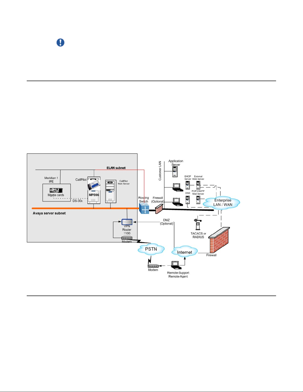
Before you connect the server to the power source, review the following diagram to ensure
that all peripheral hardware devices are in place.
Avaya CallPilot® 1005r Server Hardware Installation December 2010 45
Page 46

Connecting the server to power
Figure 10: 1005r server in a network.
To connect the 1005r AC server to power
1.
Warning:
Risk of personal injury, risk of hardware failure
The power outlets used by the CallPilot server and its peripheral devices must
be connected to the same single-point ground reference as the one used by the
switch with MGate cards connected to the CallPilot server. If this requirement is
not met, power transients can cause personal injury, hardware failure, or both.
See the Installation and Configuration Task List (NN44200-306) for more
information about single-point grounding requirements.
Plug the server AC power cords into the server rear panel.
2. Plug the other ends into an approved wall receptacle or power bar.
To start the server
1. Press the server power switch to start the server.
2. Observe the Power-On Self Test (POST) and initialization messages on the monitor.
3. Let the mini-setup sequence run until you are prompted to log on to the operating
system.
Note:
The system can perform multiple reboots. This is normal.
4. Ensure that the operating system logon window appears on the monitor.
46 Avaya CallPilot® 1005r Server Hardware Installation December 2010
Page 47

Before you begin
Note:
If the logon window does not appear, see the 1005r Server Maintenance and
Diagnostics (NN44200-704) guide for troubleshooting instructions.
5. Log into Windows.
6. CallPilot Manager wizard starts automatically.
7. Use the wizard to configure your system. For further details, see the Installation and
Configuration Task List (NN44200-306).
Avaya CallPilot® 1005r Server Hardware Installation December 2010 47
Page 48

Connecting the server to power
48 Avaya CallPilot® 1005r Server Hardware Installation December 2010
Page 49

Chapter 6: EMC emission level protection
for the 1005r Server
To lower the EMC emission level, ferrite cores are installed with one loop (see the following
diagram) on the following external cables:
Ferrite Core (TDK and part number ZCAT3035-1330)—for the triple DS30X I/O cable (Avaya
and part number NTRH2014E6). There are three ferrite cores at each end of the cable.
Caution:
Risk of equipment damage
The ferrite cores are preinstalled on the provided cables. It is not your responsibility to attach
these ferrite cores to these cables. However, you must ensure that these ferrite cores are
in place to keep the EMC emission levels low.
Avaya CallPilot® 1005r Server Hardware Installation December 2010 49
Page 50

EMC emission level protection for the 1005r Server
Figure 11: Ferrite cores secured to an external cable
The ferrite cores are secured to the appropriate cable with plastic enclosure clips. Tie wraps
are added to the cable loop.
50 Avaya CallPilot® 1005r Server Hardware Installation December 2010
Page 51

Index
Numerics
1005r server
back panel ............................................................12
dimensions and weight ........................................10
ELAN
connection, establishing ................................
environmental specifications ................................10
front bezel
removing ........................................................29
replacing ........................................................31
front panel ............................................................10
installing ...............................................................31
PCI card slots .......................................................15
PCI riser assembly ...............................................13
peripheral devices, supported ..............................20
power connection, establishing ............................45
starting .................................................................45
A
Avaya Server Subnet
connecting the server ...........................................38
C
mouse ..................................................................20
diagram
1005r server in network .......................................45
back panel ................................................12, 34, 44
slot locations ..................................................12
connection
37
dimensions, 1005r server ...........................................10
distributor .....................................................................7
documentation ........................................................7, 20
dongle .........................................................................39
network, CS 1000 and CallPilot server ..........17
network, M1 and CallPilot server ...................17
dongle
installed .........................................................39
installing ........................................................39
without feature key ........................................39
front bezel ............................................................29
front panel ............................................................10
PCI and ISA connectors .......................................13
PCI riser ...............................................................13
server connections for the power cord and
peripherals ..............................................34
SLR75 tape drive .................................................34
map ......................................................................20
installing ...............................................................39
checklist, installation ...................................................25
CLAN
media access control address .............................38
connecting peripherals to the server ..........................34
connecting the server .................................................45
connectivity
Ethernet ...............................................................18
remote ..................................................................19
CS 1000 and CallPilot server network diagram ..........17
Customer LAN
see CLAN .............................................................38
customer service ..........................................................7
D
devices, peripheral
Ethernet hub ........................................................20
keyboard ..............................................................20
modem .................................................................20
monitor .................................................................20
E
ELAN
connecting to the server .......................................37
environmental specifications ......................................10
equipment
unpacking .............................................................28
Ethernet hub
description ............................................................20
F
fax modem
required equipment ..............................................33
features
server .....................................................................9
features, front panel
diagram ................................................................10
front bezel .............................................................29, 31
removing ..............................................................29
Avaya CallPilot® 1005r Server Hardware Installation December 2010 51
Page 52

replacing ..............................................................31
I
illustration
TLAN ....................................................................17
installation checklist ....................................................25
IRQ mapping table .....................................................16
K
keyboard
connecting to the server .......................................34
description ............................................................20
keylock .......................................................................39
Ethernet hub ........................................................20
keyboard ..............................................................20
modem .................................................................20
monitor .................................................................20
mouse ..................................................................20
power connection
AC server .............................................................45
power distribution rationale ........................................44
power supply
connecting server to power ..................................45
module location ....................................................44
overview ...............................................................44
rack power and grounding ...................................44
protocols, supported network .....................................18
R
M
M1 and CallPilot server network diagram ...................17
modem ............................................................20, 33, 34
connecting to the server .......................................34
description ............................................................20
required equipment ..............................................33
monitor
connecting to the server .......................................34
description ............................................................20
mouse
connecting to the server .......................................34
description ............................................................20
N
network
connectivity ..........................................................16
protocols, supported ............................................18
network interface cards ..............................................18
P
part number
Ethernet hub ........................................................20
keyboard ..............................................................20
modem .................................................................20
monitor .................................................................20
mouse ..................................................................20
PCI and ISA connectors
diagram ................................................................13
PCI card slots .............................................................15
peripheral devices .................................................20, 34
connecting to the server .......................................34
rack power and grounding ..........................................44
remote access
connectivity ..........................................................19
reseller .........................................................................7
S
safety information .......................................................43
SCSI tape drive
connecting to the server .......................................34
serial number of the server .........................................39
server
connecting peripherals .........................................34
environmental specifications ................................10
power connection .................................................45
serial number .......................................................39
slot
assignments .........................................................15
configuration ........................................................15
software feature key ...................................................39
specifications, environmental .....................................10
T
telephony LAN
See TLAN ............................................................17
TLAN
illustration .............................................................17
training .........................................................................7
U
unpacking
52 Avaya CallPilot® 1005r Server Hardware Installation December 2010
Page 53

equipment ............................................................28
W
warnings, conventions ................................................27
weight, 1005r server ...................................................10
Avaya CallPilot® 1005r Server Hardware Installation December 2010 53
Page 54

54 Avaya CallPilot® 1005r Server Hardware Installation December 2010
 Loading...