

Avaya CallPilot 1002rp Maintenance And Diagnostics

Avaya CallPilot® 1002rp Server
Maintenance and Diagnostics
5.0
NN44200-701, 01.05
December 2010

© 2010 Avaya Inc.
All Rights Reserved.
Notice
While reasonable efforts have been made to ensure that the
information in this document is complete and accurate at the time of
printing, Avaya assumes no liability for any errors. Avaya reserves the
right to make changes and corrections to the information in this
document without the obligation to notify any person or organization of
such changes.
Documentation disclaimer
“Documentation” means information published by Avaya in varying
mediums which may include product information, operating instructions
and performance specifications that Avaya generally makes available
to users of its products. Documentation does not include marketing
materials. Avaya shall not be responsible for any modifications,
additions, or deletions to the original published version of
documentation unless such modifications, additions, or deletions were
performed by Avaya. End User agrees to indemnify and hold harmless
Avaya, Avaya's agents, servants and employees against all claims,
lawsuits, demands and judgments arising out of, or in connection with,
subsequent modifications, additions or deletions to this documentation,
to the extent made by End User.
Link disclaimer
Avaya is not responsible for the contents or reliability of any linked Web
sites referenced within this site or documentation provided by Avaya.
Avaya is not responsible for the accuracy of any information, statement
or content provided on these sites and does not necessarily endorse
the products, services, or information described or offered within them.
Avaya does not guarantee that these links will work all the time and has
no control over the availability of the linked pages.
Warranty
Avaya provides a limited warranty on its Hardware and Software
(“Product(s)”). Refer to your sales agreement to establish the terms of
the limited warranty. In addition, Avaya’s standard warranty language,
as well as information regarding support for this Product while under
warranty is available to Avaya customers and other parties through the
Avaya Support Web site:
you acquired the Product(s) from an authorized Avaya reseller outside
of the United States and Canada, the warranty is provided to you by
said Avaya reseller and not by Avaya.
Licenses
THE SOFTWARE LICENSE TERMS AVAILABLE ON THE AVAYA
WEBSITE,
APPLICABLE TO ANYONE WHO DOWNLOADS, USES AND/OR
INSTALLS AVAYA SOFTWARE, PURCHASED FROM AVAYA INC.,
ANY AVAYA AFFILIATE, OR AN AUTHORIZED AVAYA RESELLER
(AS APPLICABLE) UNDER A COMMERCIAL AGREEMENT WITH
AVAYA OR AN AUTHORIZED AVAYA RESELLER. UNLESS
OTHERWISE AGREED TO BY AVAYA IN WRITING, AVAYA DOES
NOT EXTEND THIS LICENSE IF THE SOFTWARE WAS OBTAINED
FROM ANYONE OTHER THAN AVAYA, AN AVAYA AFFILIATE OR AN
AVAYA AUTHORIZED RESELLER; AVAYA RESERVES THE RIGHT
TO TAKE LEGAL ACTION AGAINST YOU AND ANYONE ELSE
USING OR SELLING THE SOFTWARE WITHOUT A LICENSE. BY
INSTALLING, DOWNLOADING OR USING THE SOFTWARE, OR
AUTHORIZING OTHERS TO DO SO, YOU, ON BEHALF OF
YOURSELF AND THE ENTITY FOR WHOM YOU ARE INSTALLING,
DOWNLOADING OR USING THE SOFTWARE (HEREINAFTER
REFERRED TO INTERCHANGEABLY AS “YOU” AND “END USER”),
AGREE TO THESE TERMS AND CONDITIONS AND CREATE A
BINDING CONTRACT BETWEEN YOU AND AVAYA INC. OR THE
APPLICABLE AVAYA AFFILIATE (“AVAYA”).
HTTP://SUPPORT.AVAYA.COM/LICENSEINFO/ ARE
http://support.avaya.com. Please note that if
Copyright
Except where expressly stated otherwise, no use should be made of
materials on this site, the Documentation, Software, or Hardware
provided by Avaya. All content on this site, the documentation and the
Product provided by Avaya including the selection, arrangement and
design of the content is owned either by Avaya or its licensors and is
protected by copyright and other intellectual property laws including the
sui generis rights relating to the protection of databases. You may not
modify, copy, reproduce, republish, upload, post, transmit or distribute
in any way any content, in whole or in part, including any code and
software unless expressly authorized by Avaya. Unauthorized
reproduction, transmission, dissemination, storage, and or use without
the express written consent of Avaya can be a criminal, as well as a
civil offense under the applicable law.
Third-party components
Certain software programs or portions thereof included in the Product
may contain software distributed under third party agreements (“Third
Party Components”), which may contain terms that expand or limit
rights to use certain portions of the Product (“Third Party Terms”).
Information regarding distributed Linux OS source code (for those
Products that have distributed the Linux OS source code), and
identifying the copyright holders of the Third Party Components and the
Third Party Terms that apply to them is available on the Avaya Support
Web site:
Trademarks
The trademarks, logos and service marks (“Marks”) displayed in this
site, the Documentation and Product(s) provided by Avaya are the
registered or unregistered Marks of Avaya, its affiliates, or other third
parties. Users are not permitted to use such Marks without prior written
consent from Avaya or such third party which may own the Mark.
Nothing contained in this site, the Documentation and Product(s)
should be construed as granting, by implication, estoppel, or otherwise,
any license or right in and to the Marks without the express written
permission of Avaya or the applicable third party.
Avaya is a registered trademark of Avaya Inc.
All non-Avaya trademarks are the property of their respective owners,
and “Linux” is a registered trademark of Linus Torvalds.
Downloading Documentation
For the most current versions of Documentation, see the Avaya
Support Web site:
Contact Avaya Support
Avaya provides a telephone number for you to use to report problems
or to ask questions about your Product. The support telephone number
is 1-800-242-2121 in the United States. For additional support
telephone numbers, see the Avaya Web site:
Japan Denan statement
The following applies to server models 1006r, 1005r, 703t, and 1002rp:
http://support.avaya.com/Copyright.
http://support.avaya.com.
http://support.avaya.com.
2 Avaya CallPilot® 1002rp Server Maintenance and Diagnostics December 2010
Japan VCCI statement
The following applies to server models 1006r, 1005r, 703t, 201i, and
1002rp:
This is a Class A product based on the standard of the Voluntary Control
Council for Interference by Information Technology Equipment (VCCI).
If this equipment is used in a domestic environment, radio disturbance
may occur, in which case, the user may be required to take corrective
action.
Avaya CallPilot® 1002rp Server Maintenance and Diagnostics December 2010 3

4 Avaya CallPilot® 1002rp Server Maintenance and Diagnostics December 2010

Contents
Chapter 1: Customer service..................................................................................................11
Getting technical documentation.....................................................................................................................11
Getting product training...................................................................................................................................11
Getting help from a distributor or reseller........................................................................................................11
Getting technical support from the Avaya Web site........................................................................................12
Chapter 2: About this guide...................................................................................................13
In this chapter..................................................................................................................................................13
Maintenance and diagnostics overview..........................................................................................................13
Replacement parts..........................................................................................................................................14
Preparing for maintenance activities...............................................................................................................14
Customer Documentation Map.......................................................................................................................14
Chapter 3: Troubleshooting your Avaya CallPilot® system................................................19
In this chapter..................................................................................................................................................19
Startup diagnostics overview..........................................................................................................................19
Types of startup diagnostics............................................................................................................................19
Basic hardware check.....................................................................................................................................20
Power-On Self-Test diagnostics......................................................................................................................20
Interpreting POST diagnostics........................................................................................................................21
POST beep codes...........................................................................................................................................21
Interpreting startup diagnostics from SCSI BIOS............................................................................................22
Applicable cards..............................................................................................................................................22
What to do when the server fails to boot into service......................................................................................23
To determine why the server failed to boot into CallPilot................................................................................23
Chapter 4: Using Windows online diagnostic tools.............................................................25
In this chapter..................................................................................................................................................25
Overview.........................................................................................................................................................25
Viewing event logs..........................................................................................................................................25
Types of event logs.........................................................................................................................................26
Using TCP/IP diagnostic tools.........................................................................................................................29
The ipconfig command....................................................................................................................................29
ipconfig default................................................................................................................................................29
ipconfig command syntax................................................................................................................................29
The ping command.........................................................................................................................................30
Ping command syntax.....................................................................................................................................30
The tracert command......................................................................................................................................31
How tracert works...........................................................................................................................................32
Tracert syntax..................................................................................................................................................32
Tracert parameters..........................................................................................................................................32
The arp command...........................................................................................................................................33
ARP command syntax.....................................................................................................................................33
ARP command parameters.............................................................................................................................34
The nbtstat command.....................................................................................................................................34
Nbtstat command syntax.................................................................................................................................35
nbstat command parameters..........................................................................................................................35
The netstat command.....................................................................................................................................36
Netstat command syntax.................................................................................................................................36
Avaya CallPilot® 1002rp Server Maintenance and Diagnostics December 2010 5

netstat command parameters.........................................................................................................................36
Using the chkdsk utility....................................................................................................................................37
Chkdsk utility syntax........................................................................................................................................37
Chksdsk utility parameters..............................................................................................................................37
Chapter 5: Using serial port diagnostic tools.......................................................................39
In this chapter..................................................................................................................................................39
Overview.........................................................................................................................................................39
Shutting down services...................................................................................................................................39
Services to stop for COM1 testing..................................................................................................................40
Services to stop for COM2 testing..................................................................................................................40
Net Stop command.........................................................................................................................................40
Net stop command syntax...............................................................................................................................40
Service Control (SC) command......................................................................................................................41
Service Control command syntax...................................................................................................................41
Conducting TSTSERIO tests..........................................................................................................................42
TSTSERIO command syntax..........................................................................................................................42
TSTSERIO command parameters..................................................................................................................42
TSTSERIO internal loopback diagnostic subtests..........................................................................................43
TSTSERIO external loopback plug subtests...................................................................................................44
Conducting TSTSERIO tests with the loopback plug......................................................................................44
9-pin connector plug........................................................................................................................................45
Restarting services..........................................................................................................................................45
Services to restart after COM1 testing............................................................................................................45
Services to restart after COM2 testing............................................................................................................45
Net Start command.........................................................................................................................................46
Service Control Start command......................................................................................................................46
Chapter 6: Using Avaya CallPilot® Manager to monitor hardware.....................................47
In this chapter..................................................................................................................................................47
Understanding fault management...................................................................................................................47
Event processing.............................................................................................................................................48
Alarm notification.............................................................................................................................................48
Component dependencies..............................................................................................................................48
Detecting hardware problems.........................................................................................................................49
Alarm Monitor..................................................................................................................................................49
About alarms...................................................................................................................................................49
Event Browser.................................................................................................................................................50
About events...................................................................................................................................................50
Channel and Multimedia Monitors...................................................................................................................51
Disabling call channels....................................................................................................................................51
The Maintenance screen.................................................................................................................................51
What the Maintenance screen provides..........................................................................................................52
Maintenance activities for each component....................................................................................................53
Viewing component states..............................................................................................................................53
Component states...........................................................................................................................................54
Alert icons.......................................................................................................................................................55
Starting and stopping components..................................................................................................................55
Stop versus courtesy stop...............................................................................................................................56
Courtesy stop..................................................................................................................................................56
Stop.................................................................................................................................................................56
Components that can be started and stopped................................................................................................56
6 Avaya CallPilot® 1002rp Server Maintenance and Diagnostics December 2010

Running integrated diagnostics.......................................................................................................................58
Before you begin.............................................................................................................................................58
Components that have diagnostic tests available...........................................................................................58
Diagnostic tests available for each component...............................................................................................59
If a diagnostic test fails or cannot be run.........................................................................................................59
Viewing the last diagnostic results..................................................................................................................60
Working with the Multimedia Monitor..............................................................................................................61
Working with the Channel Monitor..................................................................................................................62
Chapter 7: Using Avaya CallPilot® system utilities.............................................................63
In this chapter..................................................................................................................................................63
Overview.........................................................................................................................................................63
Accessing the system utilities.........................................................................................................................64
Diagnostics Tool..............................................................................................................................................64
To access the Diagnostics Tool.......................................................................................................................64
To enable startup diagnostics..........................................................................................................................65
To disable startup diagnostics.........................................................................................................................65
PEP Maintenance utility..................................................................................................................................65
To access the PEP Maintenance utility...........................................................................................................65
Session Trace.................................................................................................................................................66
To access the session trace tool.....................................................................................................................66
System Monitor...............................................................................................................................................68
To access the System Monitor........................................................................................................................68
Channel Monitor tab........................................................................................................................................68
CallPilot services.............................................................................................................................................70
DSPs...............................................................................................................................................................71
DS30X links.....................................................................................................................................................71
T1 Links...........................................................................................................................................................71
System Info tab...............................................................................................................................................71
Legend/Help tab..............................................................................................................................................72
Chapter 8: Replacing basic chassis components................................................................75
In this chapter..................................................................................................................................................75
Removing the front bezel and server cover....................................................................................................75
Requirements..................................................................................................................................................76
About the front bezel doors.............................................................................................................................76
To remove the front bezel................................................................................................................................76
To replace the front bezel after maintenance is complete...............................................................................78
Replacing air filters..........................................................................................................................................79
Requirements..................................................................................................................................................79
Replacing the power supply............................................................................................................................79
Requirements..................................................................................................................................................80
When to hot-swap the power supply...............................................................................................................80
Replacing the SCA SCSI drive cage and fused power cable..........................................................................81
Replacing the cooling fan................................................................................................................................87
When to hot-swap the cooling fan...................................................................................................................87
Replacing the fuse (AC system only)..............................................................................................................89
Requirements..................................................................................................................................................89
Replacing the alarm board..............................................................................................................................90
Requirements..................................................................................................................................................91
Setting jumpers on the alarm board................................................................................................................92
Jumper descriptions........................................................................................................................................93
Avaya CallPilot® 1002rp Server Maintenance and Diagnostics December 2010 7

JP6 - do not change........................................................................................................................................93
JP5 - Disarming no power in the bottom bay..................................................................................................94
JP4..................................................................................................................................................................94
JP3 - LED display............................................................................................................................................94
Replacing the status display panel..................................................................................................................94
Chapter 9: Replacing media drives........................................................................................97
In this chapter..................................................................................................................................................97
Replacing a faulty hard drive...........................................................................................................................97
When to hot-swap hard drives........................................................................................................................97
RAID SCSI hard drive configuration................................................................................................................98
About the media drive bay............................................................................................................................100
Removing the media drive carrier from the chassis......................................................................................101
Requirements................................................................................................................................................101
Locate the media drives................................................................................................................................101
Media drive carrier........................................................................................................................................102
Media drive carrier slot assignment..............................................................................................................102
Replacing a tape, CD-ROM or floppy drive...................................................................................................104
Installing a tape drive....................................................................................................................................106
To configure the tape drive............................................................................................................................107
Chapter 10: RAID operations................................................................................................109
In this chapter................................................................................................................................................109
Outlining RAID functions...............................................................................................................................109
Configuring RAID firmware, driver, and power console................................................................................109
Verifying the RAID configuration...................................................................................................................109
Replacing the LSI1600 or LSI320-2 card with LSI320-2...............................................................................110
Configuring the RAID controller after a hardware change.............................................................................112
Splitting the RAID drives................................................................................................................................114
Full data backup............................................................................................................................................114
Verifying consistency on the drives...............................................................................................................114
Synchronizing RAID drives............................................................................................................................116
Chapter 11: Configuring MPB96 boards..............................................................................119
In this section.................................................................................................................................................119
Determining board and card configuration....................................................................................................119
T1 switch connectivity....................................................................................................................................119
Meridian 1 (M1)/Avaya Communication Server 1000 (Avaya CS 1000) switch connectivity.........................119
Taking safety precautions..............................................................................................................................120
Identifying hardware components.................................................................................................................120
Installing valid configurations........................................................................................................................122
T1 switch connectivity...................................................................................................................................122
M1/CS 1000 switch connectivity...................................................................................................................124
To configure one MPB96 board.....................................................................................................................124
Chapter 12: Replacing or adding voice processing boards..............................................125
In this chapter................................................................................................................................................125
DSP numbering and location........................................................................................................................125
DSP numbering on MPB96 boards...............................................................................................................125
Replacing an MPB96 board..........................................................................................................................126
Adding an MPB16/MPB96 board or replacing MPB16 with MPB96 in a 1002rp..........................................128
8 Avaya CallPilot® 1002rp Server Maintenance and Diagnostics December 2010

Chapter 13: Replacing the D/480JCT-2T1 T1 interface card..............................................131
In this chapter................................................................................................................................................131
TD/480JCT-2T1 card function.......................................................................................................................131
Replacing the D/480JCT-2T1 card................................................................................................................131
Requirements................................................................................................................................................131
Identify the card.............................................................................................................................................132
Manually setting T1 card manual termination jumpers..................................................................................133
To test the D/480JCT-2T1 card.....................................................................................................................133
Chapter 14: Maintaining the Pentium III SBC card.............................................................137
In this chapter................................................................................................................................................137
Overview.......................................................................................................................................................137
Procedures included.....................................................................................................................................138
Replacing the Pentium III SBC card..............................................................................................................138
Requirements................................................................................................................................................139
SBC card connectors and jumpers...............................................................................................................139
Configuring the 1002rp Pentium III BIOS......................................................................................................141
When to upgrade the BIOS...........................................................................................................................141
When to configure the BIOS.........................................................................................................................141
Requirements for upgrading or reconfiguring the BIOS................................................................................142
To upgrade the BIOS.....................................................................................................................................142
Replacing or adding dual inline memory modules........................................................................................143
Capacity........................................................................................................................................................143
Requirements................................................................................................................................................144
Maintaining the onboard video and network cards........................................................................................145
Network card failure......................................................................................................................................145
Video card failure..........................................................................................................................................145
Indicators for video card failure.....................................................................................................................145
Index.......................................................................................................................................147
Avaya CallPilot® 1002rp Server Maintenance and Diagnostics December 2010 9

10 Avaya CallPilot® 1002rp Server Maintenance and Diagnostics December 2010

Chapter 1: Customer service
Visit the Avaya Web site to access the complete range of services and support that Avaya provides. Go
to www.avaya.com or go to one of the pages listed in the following sections.
Navigation
Getting technical documentation on page 11
•
• Getting product training on page 11
• Getting help from a distributor or reseller on page 11
Getting technical support from the Avaya Web site on page 12
•
Getting technical documentation
To download and print selected technical publications and release notes directly from the
Internet, go to
www.avaya.com/support.
Getting product training
Ongoing product training is available. For more information or to register, you can access the
Web site at www.avaya.com/support. From this Web site, you can locate the Training contacts
link on the left-hand navigation pane.
Getting help from a distributor or reseller
If you purchased a service contract for your Avaya product from a distributor or authorized
reseller, contact the technical support staff for that distributor or reseller for assistance.
Avaya CallPilot® 1002rp Server Maintenance and Diagnostics December 2010 11

Customer service
Getting technical support from the Avaya Web site
The easiest and most effective way to get technical support for Avaya products is from the
Avaya Technical Support Web site at www.avaya.com/support.
12 Avaya CallPilot® 1002rp Server Maintenance and Diagnostics December 2010

Chapter 2: About this guide
In this chapter
Maintenance and diagnostics overview on page 13
Maintenance and diagnostics overview
The maintenance and diagnostic activities discussed in this guide are divided into two groups of
activities:
• troubleshooting and diagnostics (identifying the cause of system problems and resolving
them)
• performing hardware maintenance
This guide is for administrators, technicians, and engineers responsible for maintaining an
Avaya CallPilot® server. This guide assumes that you have basic computing skills, and are
familiar with necessary safety procedures.
If you are not able to resolve your system problem with the resources described in this guide,
you can also refer to the following document:
Troubleshooting Guide (NN44200-700)
Note:
Avaya continually updates the Troubleshooting Guide, which is available at
www.avaya.com/support.
The "Starting up and shutting down the CallPilot server" chapter in the Installation and
Configuration Task List (NN44200-306) explains how to restart, shut down, and power up the
Avaya CallPilot server. You may be asked to perform one or more of these tasks while
maintaining your server.
When you purchased your CallPilot server, it came preinstalled with the Windows operating
system and CallPilot server software. If your CallPilot server no longer functions because of a
software problem, you may need to reinstall the CallPilot software or rebuild the system.
Avaya CallPilot® 1002rp Server Maintenance and Diagnostics December 2010 13

About this guide
Replacement parts
Before replacing any parts on your server, refer to the Avaya product catalog for the part codes.
Caution:
Risk of system damage
The use of parts that are not supplied by Avaya can cause serious system problems or void
your Avaya warranty.
Preparing for maintenance activities
Before you proceed with hardware maintenance activities, review the 1002rp Server Hardware
Installation (NN44200-300) guide for the following information:
• required tools and equipment
• recommended safety precautions for electrostatic discharge, handling cards, and
handling your server
• instructions for shutting down your 1002rp server or for taking it out of service
Customer Documentation Map
The following diagram shows the overall organization and content of the CallPilot
documentation suite.
Table 1: CallPilot Customer Documentation Map
Fundamentals
Avaya CallPilot® Fundamentals Guide (NN44200-100)
Avaya CallPilot® Library Listing (NN44200-117)
Planning and Engineering
Avaya CallPilot® Planning and Engineering Guide (NN44200-200)
Avaya CallPilot® Network Planning Guide (NN44200-201)
Avaya Communication Server 1000 Converging the Data Network with VoIP
Fundamentals (NN43001-260)
14 Avaya CallPilot® 1002rp Server Maintenance and Diagnostics December 2010

Solution Integration Guide for Avaya Communication Server 1000/CallPilot®/NES
Contact Center/Telephony Manager (NN49000-300)
Installation and Configuration
Avaya CallPilot® Upgrade and Platform Migration Guide (NN44200-400)
Avaya CallPilot® High Availability: Installation and Configuration (NN44200-311)
Avaya CallPilot® Geographic Redundancy Application Guide (NN44200-322)
Avaya CallPilot® Installation and Configuration Task List Guide (NN44200-306)
Avaya CallPilot® Quickstart Guide (NN44200-313)
Avaya CallPilot® Installer Roadmap (NN44200-314)
Server Installation Guides
Avaya CallPilot® 201i Server Hardware Installation Guide (NN44200-301)
Avaya CallPilot® 202i Server Hardware Installation Guide (NN44200-317)
Avaya CallPilot® 202i Installer Roadmap (NN44200-319)
Avaya CallPilot® 703t Server Hardware Installation Guide (NN44200-304)
Customer Documentation Map
Avaya CallPilot® 1002rp Server Hardware Installation Guide
(NN44200-300)
Avaya CallPilot® 1002rp System Evaluation (NN44200-318)
Avaya CallPilot® 1005r Server Hardware Installation Guide
(NN44200-308)
Avaya CallPilot® 1005r System Evaluation (NN44200-316)
Avaya CallPilot® 1006r Server Hardware Installation Guide
(NN44200-320)
Avaya CallPilot® 600r Server Hardware Installation Guide
(NN44200-307)
Avaya CallPilot® 600r System Evaluation (NN44200-315)
Configuration and Testing Guides
Avaya Meridian 1 and Avaya CallPilot® Server Configuration Guide
(NN44200-302)
Avaya T1/SMDI and Avaya CallPilot® Server Configuration Guide
(NN44200-303)
Avaya Communication Server 1000 System and Avaya CallPilot® Server
Configuration Guide (NN44200-312)
Unified Messaging Software Installation
Avaya CallPilot® Desktop Messaging and My CallPilot Installation and
Administration Guide (NN44200-305)
Administration
Avaya CallPilot® 1002rp Server Maintenance and Diagnostics December 2010 15

About this guide
Maintenance
Avaya CallPilot® Administrator Guide (NN44200-601)
Avaya CallPilot® Software Administration and Maintenance Guide (NN44200-600)
Avaya Meridian Mail to Avaya CallPilot® Migration Utility Guide (NN44200-502)
Avaya CallPilot® Application Builder Guide (NN44200-102)
Avaya CallPilot® Reporter Guide (NN44200-603)
Avaya CallPilot® Troubleshooting Reference Guide (NN44200-700)
Avaya CallPilot® Preventative Maintenance Guide (NN44200-505)
Server Maintenance and Diagnostics
Avaya CallPilot® 201i Server Maintenance and Diagnostics Guide
(NN44200-705)
Avaya CallPilot® 202i Server Maintenance and Diagnostics Guide
(NN44200-708)
Avaya CallPilot® 703t Server Maintenance and Diagnostics Guide
(NN44200-702)
Avaya CallPilot® 1002rp Server Maintenance and Diagnostics Guide
(NN44200-701)
Avaya CallPilot® 1005r Server Maintenance and Diagnostics Guide
(NN44200-704)
Avaya CallPilot® 1006r Server Maintenance and Diagnostics Guide
(NN44200-709)
Avaya CallPilot® 600r Server Maintenance and Diagnostics Guide
(NN44200-703)
Avaya NES Contact Center Manager Communication Server 1000/
Meridian 1 & Voice Processing Guide (297-2183-931)
End User Information
End User Cards
Avaya CallPilot® Unified Messaging Quick Reference Card
(NN44200-111)
Avaya CallPilot® Unified Messaging Wallet Card (NN44200-112)
Avaya CallPilot® A-Style Command Comparison Card (NN44200-113)
Avaya CallPilot® S-Style Command Comparison Card (NN44200-114)
Avaya CallPilot® Menu Interface Quick Reference Card (NN44200-115)
Avaya CallPilot® Alternate Command Interface Quick Reference Card
(NN44200-116)
Avaya CallPilot® Multimedia Messaging User Guide (NN44200-106)
16 Avaya CallPilot® 1002rp Server Maintenance and Diagnostics December 2010

Customer Documentation Map
Avaya CallPilot® Speech Activated Messaging User Guide
(NN44200-107)
Avaya CallPilot® Desktop Messaging User Guide for Microsoft Outlook
(NN44200-103)
Avaya CallPilot® Desktop Messaging User Guide for Lotus Notes
(NN44200-104)
Avaya CallPilot® Desktop Messaging User Guide for Novell Groupwise
(NN44200-105)
Avaya CallPilot® Desktop Messaging User Guide for Internet Clients
(NN44200-108)
Avaya CallPilot® Desktop Messaging User Guide for My CallPilot
(NN44200-109)
Avaya CallPilot® Voice Forms Transcriber User Guide (NN44200-110)
The Map was created to facilitate navigation through the suite by showing the main task groups
and the documents contained in each category. It appears near the beginning of each guide,
showing that guide's location within the suite.
Avaya CallPilot® 1002rp Server Maintenance and Diagnostics December 2010 17

About this guide
18 Avaya CallPilot® 1002rp Server Maintenance and Diagnostics December 2010

Chapter 3: Troubleshooting your Avaya
CallPilot® system
In this chapter
Startup diagnostics overview on page 19
Basic hardware check on page 20
Power-On Self-Test diagnostics on page 20
Interpreting POST diagnostics on page 21
Interpreting startup diagnostics from SCSI BIOS on page 22
What to do when the server fails to boot into service on page 23
Startup diagnostics overview
This section contains procedures for interpreting the startup diagnostics on the 1002rp server.
Types of startup diagnostics
The following types of startup diagnostics are available on the server:
• basic hardware check (for example LEDs)
• Power-On Self-Test (POST) diagnostics
• SCSI controller diagnostics or RAID controller diagnostics
These diagnostics are available at initial system startup, or after any 1002rp server reset.
Avaya CallPilot® 1002rp Server Maintenance and Diagnostics December 2010 19

Troubleshooting your Avaya CallPilot® system
Basic hardware check
This section describes some basic checks that you can do when you start up the server.
To run the startup test
1. Power on the server and observe the front panel display.
Result: All LEDs on the panel illuminate for a few seconds. The green power LED
remains illuminated.
2. Observe the following server actions:
• Cooling fans on the front panel start up, and the red fault LED next to each fan
extinguishes.
• Drives spin up, and the amber hard drive activity LEDs over the front panel
display extinguish, and then flash with activity.
• LEDs illuminate temporarily as the system checks the floppy drive, tape drive,
and CD-ROM drive.
• The LED on each power supply lights up red as supply fans spin up and
components charge. LEDs turn green when the attached power supply is fully
operational.
3. Check the monitor for any error messages as the server counts RAM and completes
a POST.
Power-On Self-Test diagnostics on page 20 for more details on POST.
See
Power-On Self-Test diagnostics
The Power-On Self-Test (POST) is a system diagnostic program (stored in the BIOS) that runs
each time the 1002rp server is started. The function of the POST is to test system components
and then display status messages.
To run the POST
1. Power up the Avaya CallPilot server and monitor.
Result: After a few seconds, POST begins to run.
After the memory test, various screen prompts and messages appear. The screen
prompts may be accompanied by a single beep.
2. Observe the screen for any error messages and listen for POST beep codes. When
POST completes, the server beeps once.
20 Avaya CallPilot® 1002rp Server Maintenance and Diagnostics December 2010

If the server halts before POST is finished, the server emits a beep code indicating
that a fatal system error requires immediate attention. See Interpreting POST
diagnostics on page 21 for details.
If POST can display a message on the monitor, the server emits two beeps as the
message appears.
Record the message that appears on the monitor and the beep code that you hear.
This information is useful if you need assistance from your technical support
representative.
Interpreting POST diagnostics
This section provides an explanation of the POST diagnostic codes.
POST beep codes
Interpreting POST diagnostics
If an error occurs before video initialization, POST emits beep codes that indicate errors in
hardware, software, or firmware.
A beep code is a series of separate tones, each equal in length. Record the beep code
sequence before calling Avaya technical support.
Important:
Some POST beep codes are fatal and may require that you replace the Single Board Card
(SBC). See the table below for more information about beep codes.
Table 2: POST beep codes
Beep count Error message Description
1 Refresh Failure The memory refresh circuitry of the processor board
is faulty.
2 Parity Error A parity error was detected in the base memory (the
first block of 64 kbytes) of the system.
3 Base 64KB Memory
Failure
4 Timer Not
Operational
A memory failure occurred within the first 64 kbytes of
memory.
A memory failure occurred within the first 64 kbytes of
memory, or Timer #1 on the processor board failed to
function properly.
5 Processor Error The Central Processing Unit (CPU) on the processor
board failed to function properly.
Avaya CallPilot® 1002rp Server Maintenance and Diagnostics December 2010 21

Troubleshooting your Avaya CallPilot® system
Beep count Error message Description
6 8042 - Gate A20
Failure
7 Processor Exception
Interrupt Error
8 Display Memory
Read/Write Error
9 ROM Checksum
Error
10 CMOS Shutdown
Register Read/Write
Error
11 Cache Memory Bad:
Do Note Enable
Cache
The keyboard controller (8042) contains the Gate A20
switch, which allows the CPU to operate in protected
mode. This error message means that the BIOS
cannot switch the CPU into protected mode.
The CPU on the processor board generated an
exception interrupt.
The system video adapter is either missing or its
memory is faulty.
Note:
This is not a fatal error.
The ROM checksum value does not match the value
encoded in the BIOS.
The shutdown register for the CMOS RAM failed.
The cache memory test failed. Cache memory is
disabled.
Note:
Do not press Ctrl+Alt+Shift<+> to enable cache
memory.
Interpreting startup diagnostics from SCSI BIOS
The results from the SCSI controller diagnostics appear after the POST results.
Applicable cards
Results of the startup diagnostics appear only if you have the following cards installed on your
system:
• Adaptec SCSI controller
The adapter is integrated in the SBC and can be disabled.
• LSI Elite 1600 controller
22 Avaya CallPilot® 1002rp Server Maintenance and Diagnostics December 2010

What to do when the server fails to boot into service
What to do when the server fails to boot into service
This section suggests tasks you can perform to determine why the server fails the bootup cycle.
To determine why the server failed to boot to Windows
1. Make a note of any diagnostic codes.
2. Try restarting the server by pressing the power button on the server.
3. During the boot sequence, view the diagnostic codes on the monitor for failures.
4. Refer to the Troubleshooting Guide (NN44200-700) for other suggestions. If you
still cannot determine the cause of the startup failure, call your Avaya technical
support representative.
To determine why the server failed to boot into CallPilot
If the system-ready indicator indicates that the system is not booting into CallPilot, follow these
steps:
1. Make a note of any diagnostic codes.
2. Try restarting the server by pressing the power button on the server.
3. During the boot sequence, view the diagnostic codes on the monitor for failures.
4. View the event logs. For instructions, see
5. Refer to the Troubleshooting Guide (NN44200-700) for other suggestions. If you
still cannot determine the cause of the startup failure, call your Avaya technical
support representative.
Viewing event logs on page 25.
Avaya CallPilot® 1002rp Server Maintenance and Diagnostics December 2010 23

Troubleshooting your Avaya CallPilot® system
24 Avaya CallPilot® 1002rp Server Maintenance and Diagnostics December 2010

Chapter 4: Using Windows online
diagnostic tools
In this chapter
Overview on page 25
Viewing event logs on page 25
Using TCP/IP diagnostic tools on page 29
Using the chkdsk utility on page 37
Overview
This section describes how to access the run-time online diagnostic tools provided by the
Windows server software. Use the following tools when a serious problem prevents the use of
the Avaya CallPilot® diagnostic tools that are available in Avaya CallPilot Manager.
• Windows Event Viewer
• TCP/IP diagnostics
• chkdsk utility
Caution:
Risk of software corruption
Do not run any utilities that are not documented in this guide.
Viewing event logs
When the server startup cycle is complete, and if the CallPilot server has been configured,
messages in dialog boxes on the monitor indicate that CallPilot is ready to accept calls.
Avaya CallPilot® 1002rp Server Maintenance and Diagnostics December 2010 25

Using Windows online diagnostic tools
If one or more messages appear on the monitor, the message may contain information about
an event, or a fault may have occurred. To determine what happened, you can use the following
diagnostic tools:
• Windows Event Viewer on the 1002rp server
• CallPilot Event Browser or Alarm Monitor in CallPilot Manager
Note:
The Event Browser and Alarm Monitor include online Help for events, which may help you
to resolve the problem. If you cannot log on to the CallPilot system using a web browser due
to server problems, then use the Windows Event Viewer.
Types of event logs
Three types of event logs are available from the Windows Event Viewer, as follows:
Log type Description
System Logs events by Windows components, including RRAS or other
Windows services.
Security Logs security events, such as logons, logoffs, and illegal
access. This option is available only to users with Administrative
access.
Applications Logs events by application, such as database file errors.
To use the operating system Event Viewer
1. Click Start → Programs → Administrative Tools → Event Viewer.
Result: The Event Viewer window appears.
26 Avaya CallPilot® 1002rp Server Maintenance and Diagnostics December 2010
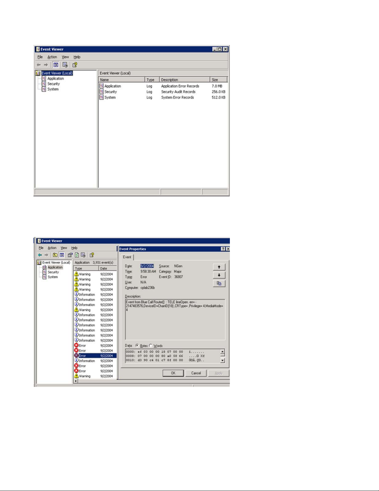
Figure 1: Event Viewer
Types of event logs
2. To view a log, click the name of the log in the left pane of the window.
The following illustration shows an example of the Application Log.
Figure 2: Application log
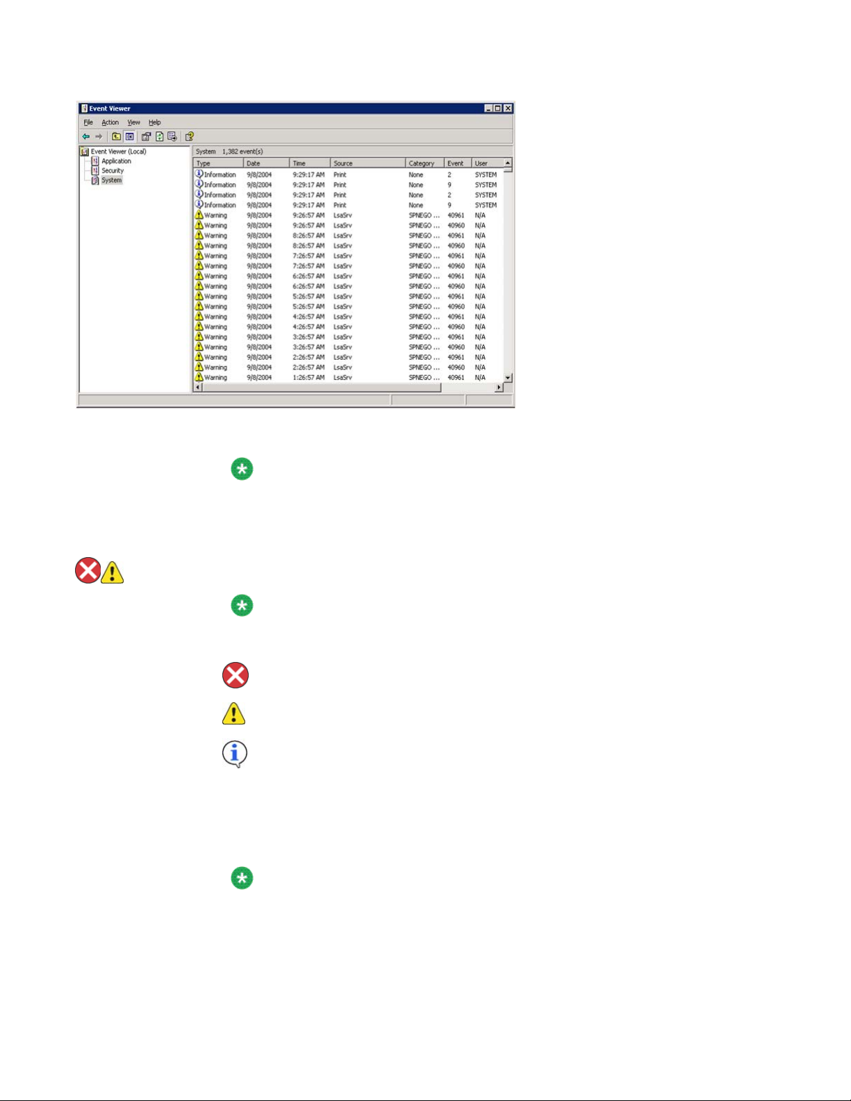
The following illustration shows an example of a System log.
Avaya CallPilot® 1002rp Server Maintenance and Diagnostics December 2010 27
Using Windows online diagnostic tools
Figure 3: System log
Note:
The Security log, which is available only to administrators, is not shown.
3. Look for error codes that have occurred since the last startup. Error codes are
flagged with the following symbols.
Note:
Each error is date- and time-stamped.
indicates major or critical errors
indicates minor errors
indicates information
4. To determine the cause of the error, select and then double-click the error.
Result: A description of the error appears in an Event detail dialog box. Use the
description to help determine how to resolve errors.
Note:
If the error persists or the error description does not suggest a solution, contact
your Avaya support representative.
5. Click Close.
28 Avaya CallPilot® 1002rp Server Maintenance and Diagnostics December 2010

Result: The event log reappears.
6. Click Log → Exit.
Result: The Event Viewer closes.
Using TCP/IP diagnostic tools
This section describes the following TCP/IP diagnostic tools which are available for the network
adapter:
• ipconfig
• ping
• tracert
• arp
• nbtstat
Using TCP/IP diagnostic tools
• netstat
These utilities help you to verify network connectivity, test the network interface, and isolate
any configuration problems.
The ipconfig command
The ipconfig command displays IP configuration information.
ipconfig default
If you run the command without flags, it displays the IP address, subnet mask, and default
gateway for each adapter bound to TCP/IP.
ipconfig command syntax
The ipconfig command uses the following syntax:
ipconfig /[ ]
Avaya CallPilot® 1002rp Server Maintenance and Diagnostics December 2010 29

Using Windows online diagnostic tools
The following flags are available for the ipconfig command.
Table 3: ipconfig command extensions
Flag Description
/? Displays Help information.
/all Displays full configuration information.
/release Releases the IP address for the specified adapter.
/renew Renews the IP address for the specified adapter.
To run the ipconfig command from Windows
1. Click Start → Programs → Accessories → Command Prompt.
Result: The Command Prompt window appears.
2. At the Command prompt, type ipconfig <parameters>.
Example: ipconfig /all
3. Press Enter.
Result: The system runs the ipconfig utility.
4. Type Exit to exit the Command Prompt window and return to Windows.
The ping command
The ping command sends an echo request to a specified host. Use this command to verify
network connectivity to the remote device.
Ping command syntax
The ping command uses the following syntax:
ping [-t] [-a] [-n count] [-l size] [-f] [-i TTL] [-v TOS] [-r count]
[-s count] [[-j host-list] | [-k host-list]] [-w timeout]
destination-list
Table 4: ping command extensions
Parameter Description
-t Pings the specified host until interrupted.
30 Avaya CallPilot® 1002rp Server Maintenance and Diagnostics December 2010
 Loading...