

Page 1

CALLMASTER® V Telephone Console
User’s Guide
Contents
The CALLMASTER V Telephone Console
The CALLMASTER V Telephone Console. . . . . . . . . . . . . . .
The CALLMASTER V Telephone ConsoleThe CALLMASTER V Telephone Console
Headset Connections with the CALLMASTER V
Headset Connections with the CALLMASTER V. . . . . . . . .
Headset Connections with the CALLMASTER VHeadset Connections with the CALLMASTER V
The CALLMASTER V Recorder Interface
The CALLMASTER V Recorder Interface. . . . . . . . . . . . . .
The CALLMASTER V Recorder InterfaceThe CALLMASTER V Recorder Interface
The Softkeys
The Softkeys . . . . . . . . . . . . . . . . . . . . . . . . . . . . . . . . .
The SoftkeysThe Softkeys
Call-Handling Features
Call-Handling Features . . . . . . . . . . . . . . . . . . . . . . . . . . .
Call-Handling FeaturesCall-Handling Features
Getting Messages
Getting Messages . . . . . . . . . . . . . . . . . . . . . . . . . . . . . . .
Getting MessagesGetting Messages
Selecting a Personalized Ring
Selecting a Personalized Ring . . . . . . . . . . . . . . . . . . . . . .
Selecting a Personalized RingSelecting a Personalized Ring
Voice and Display Features
Voice and Display Features . . . . . . . . . . . . . . . . . . . . . . . .
Voice and Display FeaturesVoice and Display Features
Operating Range Requirements
Operating Range Requirements . . . . . . . . . . . . . . . . . . . . .
Operating Range RequirementsOperating Range Requirements
. . . . . . . . . . . . . . . . . . . . . . . . . . . . . . . . .3333
. . . . . . . . . . . . . . . . . . . . . . . . . . . . . . . . .. . . . . . . . . . . . . . . . . . . . . . . . . . . . . . . . .
. . . . . . . . . . . . . . . . . . . . . . . . . . .4444
. . . . . . . . . . . . . . . . . . . . . . . . . . . . . . . . . . . . . . . . . . . . . . . . . . . . . .
. . . . . . . . . . . . . . . . . . . . . . . . . . . . . . .7777
. . . . . . . . . . . . . . . . . . . . . . . . . . . . . . .. . . . . . . . . . . . . . . . . . . . . . . . . . . . . . .
. . . . . . . . . . . . . . . . . . . . . .8888
. . . . . . . . . . . . . . . . . . . . . . . . . . . . . . . . . . . . . . . . . . . .
. . . . . . . . . . . . . . . . . . . . . . . .8888
. . . . . . . . . . . . . . . . . . . . . . . . . . . . . . . . . . . . . . . . . . . . . . . .
. . . . . . . . . . . . . . . . . . . . .9999
. . . . . . . . . . . . . . . . . . . . . . . . . . . . . . . . . . . . . . . . . .
. . . . . . . . . . . . . . .1111
. . . . . . . . . . . . . . .. . . . . . . . . . . . . . .
. . . . . . . . .2222
. . . . . . . . .. . . . . . . . .
. . . . . . . . . . . . . .3333
. . . . . . . . . . . . . .. . . . . . . . . . . . . .
Telephone Installation
Telephone Installation. . . . . . . . . . . . . . . . . . . . . . . . . . . .
Telephone InstallationTelephone Installation
Important Safety Warnings for Installation
Important Safety Warnings for Installation . . . . . . . . . . .
Important Safety Warnings for InstallationImportant Safety Warnings for Installation
Desktop Installation
Desktop Installation. . . . . . . . . . . . . . . . . . . . . . . . . . .
Desktop InstallationDesktop Installation
Wall Installation
Wall Installation . . . . . . . . . . . . . . . . . . . . . . . . . . . . .
Wall InstallationWall Installation
Installing the Designation Card
Installing the Designation Card . . . . . . . . . . . . . . . . . . .
Installing the Designation CardInstalling the Designation Card
Orderable Cards and Equipment
Orderable Cards and Equipment. . . . . . . . . . . . . . . . . . . .
Orderable Cards and EquipmentOrderable Cards and Equipment
© 2000 Avaya Inc., All Rights Reserved, Printed in USA
© 2000 Avaya Inc., All Ri ghts Res er ve d, Pr int ed in U S A
© 2000 Avaya Inc., All Ri ghts Res er ve d, Pr int ed in U S A© 2000 Avaya Inc., All Rights Reserved, Printed in USA
. . . . . . . . . . . . . . . . . . . . . . . . . . . .9999
. . . . . . . . . . . . . . . . . . . . . . . . . . . .. . . . . . . . . . . . . . . . . . . . . . . . . . . .
. . . . . . . . . . .10
. . . . . . . . . . . . . . . . . . . . . .
. . . . . . . . . . . . . . . . . . . . . . . . . . .11
. . . . . . . . . . . . . . . . . . . . . . . . . . .. . . . . . . . . . . . . . . . . . . . . . . . . . .
. . . . . . . . . . . . . . . . . . . . . . . . . . . . .12
. . . . . . . . . . . . . . . . . . . . . . . . . . . . . . . . . . . . . . . . . . . . . . . . . . . . . . . . . .
. . . . . . . . . . . . . . . . . . .13
. . . . . . . . . . . . . . . . . . .. . . . . . . . . . . . . . . . . . .
. . . . . . . . . . . . . . . . . . . .14
. . . . . . . . . . . . . . . . . . . .. . . . . . . . . . . . . . . . . . . .
555-233-735
Comcode 108742933
Issue 2
February 2000
10
1010
11
1111
12
1212
13
1313
14
1414
Page 2

NOTICE
While reasonable efforts were made to ensure that the information in this
document was complete and accurate at the time of printing, Lucent
Technologies can assume no responsibility for any errors. Changes or
corrections t o the information co ntained in this do cu me nt may be inc orpor ate d
into future issues.
TO ORDER COPIES OF THIS DOCUMENT
Contact: Avaya Publications Center
2855 N. Franklin Road,
Domestic: 1 800 457-1235 International: 1 317 322-6791
Domestic Fax: 1 800 457-1764 International Fax: 1 317 322-6699
Order: Document No. 555-233-735
Issue 2, February 2000
HEARING AID COMPATIBILITY
Indianapolis, IN 46219
The CALLMASTER V telephone console is Hearing Aid Compatible (HAC)
when used with HAC headsets, and thus all units have “HAC” printed on them.
YOUR RESPONSIBILITY FOR YOUR SYSTEM’S SECURITY
You are respon si b le for the secu rity of your system. Luc en t Techn olo gi es doe s
not warran t that this product is imm une from or will pre v ent unauthorize d use of
common-carrier telecommunication services or facilities accessed through or
connected to it. Lucent Technologies will not be responsible for any charges
that result from such unauthorized use. Product administration to prevent
unauthorized use is your responsibility and your system manager should read
all documents provided with this product to fully understand the features
available that may reduce your risk of incurring charges.
TRADEMARKS
DEFINITY, AUDIX, and CALLMASTER are registered trademarks of Lucent
Technologies.
Mirage, Star Set, and Supra are registered trademarks of Plantronics, Inc.
FCC REGULATIONS
The FCC requi res us t o prov ide the followi ng w arning for Clas s B resi dential
installations.
WARNING: This equipment has been tested and found to comply with the
limits for a Class B digital device, pursuant to Part 15 of the FCC Rules. These
limits are designed to provide reasonable protection against harmful
interference in a residential installation. This equipment generates, uses, and
can radiate r adio frequen cy energ y and, if not ins talled and used in accordance
with the instructions, may cause harmful interference to radio and television
communicati on s . However, there is no guarantee that inte rfere nc e will not
occur in a particular installation. If this equipment does cause harmful
interference to radio or television reception, which can be determined by
turning the equipment off and on, the user is encouraged to try to correct the
interference by one or more of the following measures:
• Reorient or relocate the receiving antennae.
• Increase the separation between the equipment and receiver.
• Connect the equipmen t into an o utlet on a c ircuit di fferent from that to w hich
the receiver is connected.
• Consult the dealer or an experienced radio/tv technician for help.
Page 3

OBTAINING PRODUCTS
To learn more about Lucent Technologies products and to order any of these
products, contact Lucent Direct, the direct-market organization of Lucent
Technologies Business Communications System. Access their web site at
www.lucentdirect.com or call the following numbers: customers should call
1 800 451-2100 or account executives can contact Lucent Direct at
1 800 778 1880 (voice) or 1 800 778-1881 (fax).
THE “CE” MARK
If the “CE” mark is affixed to this equipment. it means that it conforms to the
European Union Electrom agnetic Compatib ility Directiv e (89/336/EEC) and the
Low Voltage Directive (73/23/EEC).
Disclaimer
Intellectual property related to this product (including trademarks) and
registered to Lucent Technologies Inc. has been transferred or licensed to
Avaya Inc.
Any reference within the text to Lucent Technologies Inc. or Lucent should be
interpreted as references to Avaya Inc. The exception is cross references to
books pub lis he d prior to 1 /1/2001, which may retain their original Lucent titles.
Av aya Inc. formed as a result of Luc entís planne d restructu ring, de signs b uilds
and delivers voice, converged voice and data, messaging, customer
relationship management, multi-service networking and structured cabling
products and services. Avaya Labs is the research and development arm for
the company.
IMPORTANT USER SAFETY INSTRU CTIONS
The most careful attention has been devoted to quality standards in the
manufacture of your new telephone. Safety is a major factor in the design of
every set. But, safety is YOUR responsibility too.
Please read ca refu lly th e h elpful tips listed below an d o n the ne xt pag e. These
suggestions will enable you to take full advantage of your new voice terminal.
Then, retain these tips for later use.
!
CAUTION:
This telephone is NOT for residential use. It is for business systems
applications ONLY. It will NOT operate on public networks. It MUST
BE connected to a DEFINITY Enterprise Communications Server.
Use in a residential environm ent could result in an electrical sho rt
circuit when the telephone wiring is set up to provide other
applications, for example, for appliance control or power
transformers. The AC power used in thes e ap pli ca tions ma y c rea te a
safety hazard by placing a direct short circuit across the telephone
wiring.
Use
Page 4

When using y our tel ephone , the follo wi ng safet y precauti ons sho uld alw ays be
followed to reduce the risk of fire, electric shock, and injury to persons.
• Read and understand all instructions.
• Follow all warnings and instructions marked on the telephone.
• This telephone can be hazardous if immersed in water. To avoid the
possibility of electric shock, do not use it while you are wet. If you
accidentally d r op t he t ele phone into wate r, do not retrieve it until y o u h ave
first unplugg ed the li ne cord from the m od ula r wall jac k. Then, call service
personnel to ask about a replacement.
• Av oid using the tel ephone during electrical storms in your immedia te area.
There is a risk of electric shock from lightning. Urgent calls should be
brief. Even though protective measures may have been installed to limit
electrical surges from entering your business, absolute protection from
lightning is imposs ible.
• If you suspect a natural gas leak, report it immediately, but use a
telephone away from the area in question. The telephone’s electrical
contacts could generate a tiny spark. While unlikely, it is possible that this
spark could ignite heavy conc entrations of gas.
• Never push objects of any kind into the equipment through housing slots
since they may touch hazardous voltage points or short out parts that
could result in a risk of electric shock. Never spill liquid of any kind on the
telephone. If liquid is spilled, however, refer servicing to proper service
personnel.
• To reduce the risk of electric shock, do not disassemble this telephone.
There are no user serviceable parts. Opening or removing covers may
expose you to hazardous voltages. Incorrect reassembly can cause
electric shock when the telephone is subsequently used.
Service
1. Before cleaning, unplug the telephone from the modular wall jack. Do
not use liquid cleaners or aerosol cleaners. Use a damp cloth for
cleaning.
2. Unplug the telephone from the modular wall jack. Be sure to refer
servicing to qualified service personnel when these conditions exist:
– If liquid has been spilled into the telephone.
– If the telephone has been exposed to rain or water.
– If the telephone has been dropped or the housing has been
damaged.
– If you note a distinct change in the performance of the telephone.
SAVE THESE INSTRUCTIONS
When you se e this wa rning symbol on the pro duct, refer
to this instructions booklet packed with the product for
!
more information before proc eeding.
Page 5
The CALLMASTER V Telephone Console
The CALLMASTER® V telephone has b een spec ially de signed fo r use with th e
Automatic Call Distribution (ACD) system and the many features of the
DEFINITY
Communications System Generic 1, Generic 2, and Generic 3. This
telephone is designed to be used with a headset in a 2-wire environment.
Note: Power for the CALLMASTERV telephone, including the headset,
The CALLMASTER V also has a built-in Reco rder Interface which allows you
to connect the tel ephone to a recording dev ice s o th at you can rec ord a ll voice
interactions. For more information about this interface, see “The
CALLMASTER V Recorder Interface” on page 3.
Note: The tape recorder used with the CALLMASTER V telephone must be
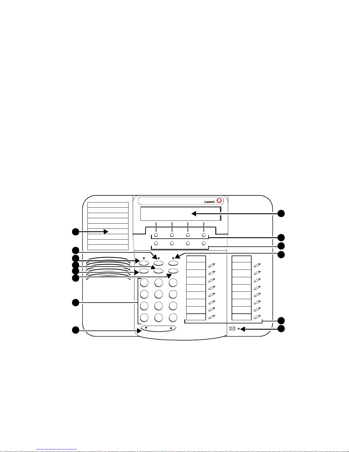
Figure 1 below shows a front view of the CALLMASTER V telephone. The
features of the telephone are explained after the figure.
Note: For a rear view of the telephone, see Figure 4 on page 9.
®
Enterprise Communications Server (ECS) and the DEFINITY
comes from the DEFINITY switch through the 2-wire DCP line.
purchased by the user; it is not provided with the telephone.
®
1
2
3
4
5
6
7
CALLMASTER V
8
Menu Exit Prev Next
Speaker
Mute Hold
Transfer
Redial
1
GHI
4
PQRS
7
*
Conf
Test
Ring
DEF
ABC
3
2
MNOJKL
56
TUV
WXYZ
8
9
O#
Volume
Tel #
FIGURE 1 The CALLMASTER V Telephone Console, Front View
9
10
11
12
13
14
1
Page 6
The following features correspond to the numbers in Figure 1.
1) Telephone Notepad 8) Volume control button
2) Mute (or ) button 9) Display
3) Speaker (or ) button 10) Softkeys
4) Transfer/Test (or ) button 11) Display control buttons
5) Redial (or ) button 12) Hold (or ) button
6) Conf/Ring (or ) button 13) Call appearance /feature buttons
(See Note immediately below)
7) Dial pad 14) Message light – labeled
Note: Two feature buttons must be administered in the following ways:
• One of the feature buttons must be designated as the
Headset On/Off button;
• The Release feature must be administered on a second feature
button.
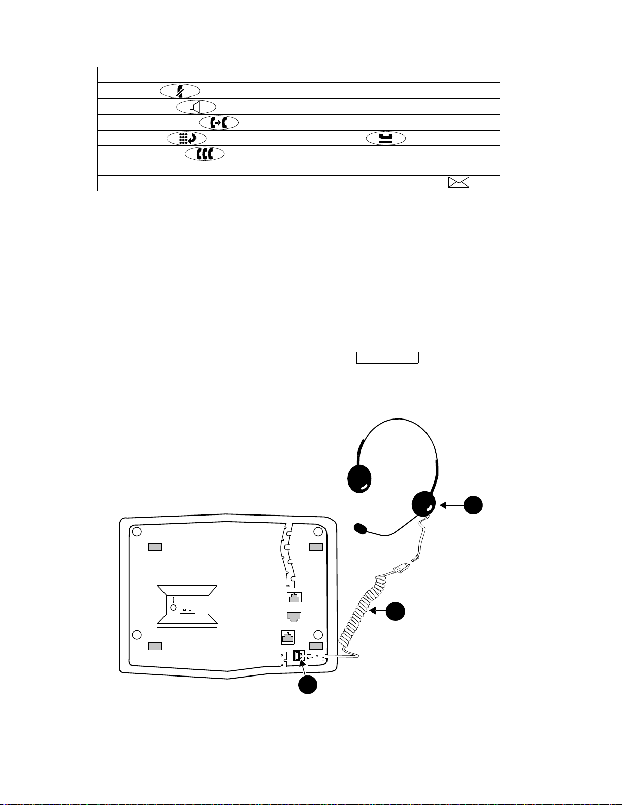
Headset Connections with the CALLMASTER V
The headset connection for the CALLMASTER V consists of a headpiece
(shown as 1 in Figure 2 below) which is plugged into an adapter cord (shown
as 2).
Note: Your system manager MUST administer a button on your
Headset On/Off
set. Use this button to turn your headset on and off. For instructions for
using this feature button, see “Headset On/Off” in the section titled
Call-Handling Features.
1
2
FIGURE 2 The Headset Connected to O ne o f the He ads et Ja cks (shown
as 3) on the CALLMASTER V Telephone
3
2
Page 7

Compatible Headpieces
The following Lucent Technologies headpieces can be used with these
telephones:
– Mirage® – Receiver fits over either ear. Not for noisy environments.
– StarSet
®
– Eartip fits in ear canal.
– Supra® – Adjustable headband and soft ear cushion.
– Encore® – Advanced sound technology with adjustable headband
and soft ear cushion.
®
– TriStar
– Advanced headpiece which fits over the ear.
The CALLMASTER V Recorder Interface
The CALLMASTER V’s Recorder Interface is designed for recording calls on a
standard tape recorder. (A recorder with AGC [Automatic Gain Control] is
recommended.) With this interf ace, a w arning tone , a soft beep repeated e v ery
13.5 seconds, notifies the agent and the calling party that the call is being
recorded. Be aware that this tone may be a legal requirement.
IMPORTANT: The use of service observing features and call recording
features ma y be subjec t to federa l, state , and local laws , rules, or regulati ons
and may be prohibited pursuant to the laws, rules, or regulations or require
the consent of one or both of the parties to the conversation. Customers
should familia rize th emselv es wi th and com ply with all applicab le la ws , rules ,
and regulations before using these features.
The Soft keys
The softkeys are the four unlabeled round keys located directly below the
display. The fou r round display control buttons, la be led Menu, Exit, Prev, and
Next are located under the softkeys. See Figure 3.
Display
Softkeys
NextPrevMenu Exit
FIGURE 3 The Display, Softkeys, and Display Control Buttons
Display
control buttons
3
Page 8

Using the Softkey Feature Menus
There are three separate softkey feature menus. Each of these menus allows
you to select from four different features.
You can enter Softkey Mode (and view the softkey feature menu) by pressing
the display control button labeled Menu or . The following is an example
of a softke y feat ure me nu.
Dir Drop HFAns Timer
The top line of each softkey feature menu screen shows you the status of
each of the four features. An arrow appears above the feature name or
abbre viation if that feature is act ive . In the abo ve e xam ple, the arro w abo ve the
Timer feature indicates that feature is active.
The second line on each softkey feature menu shows the features you can
access. To use any of these features, you must press the softkey below the
feature name or abbrevi ation.
Press the Next or Prev button un til the fe atur e y ou w ant t o use appea rs on the
display.
Note: An error tone (one beep) sounds when you have made an
inappropriate softkey entry.
Press the Exit button at any time to e xit the sof tke y feature menus and
return to normal call-handling operation.
Other Softkey Features That Ma y Be On Your Display
There are 12 default features that can be accessed with the softkeys on a
CALLMASTER V telephone. However, the system manager may substitute
other softkey features in their place.
Call-Handling Features
HEADSET ON/OFF
The system a dminist ra tor sho uld ha v e admi nistere d a button on
your CALLMASTER V telephone.
To turn on your headset
1. Press .
Headset On/Off
Headset On/Off
The green light next to the button goes on to remind you the heads et is
active.
To turn off your headset
1. Press again.
Headset On/Off
The green light next to the button goes off.
4
Page 9

CONFERENCE
The Conference fea ture allows you to conference up to six parties (including
yourself) on a call.
To add another party to a call (for a total of six parties)
1. Press (or ). [dial tone]
Conf
2. Dial t he number of the new party and wait for an answer.
3. When you want to add the new person, press (or
Conf
again.
4. Repeat Steps 1 through 3 for additional conference connections.
To add a call you have put on hold to another call you are connected to
1. Press (or
Conf
). [dial tone]
2. Press the call appearance button of the call on hold (first call).
3. Press (or
Conf
) again.
To drop the last person added to the conference call
1. With a display: Press the Menu button and then press the softkey
below Drop.
Without a display: Press the button (if administered).
Drop
HOLD
The Hold feature puts a call on hold until you can return to it.
To put a call on hold while you answer another call or perform another
task
)
1. Press (or ).
Hold
To answer a new call while active on another
1. Press (or ).
Hold
2. Press the call appearance button of the incoming call.
To return to the held call
1. Press the call appearance button of the held call.
REDIAL
The Redial (or Last Number Dialed) feature automatically redials the last
extension or outside number (up to 24 digits) you dialed.
To redial the last number that you dialed
1. Press (or
Redial
).
5
Page 10

RELEASE
An ACD agent can press to disconnect from a call.
Release
To disconnect from a call
1. Press .
Note: Pressing is faster than waiting for a caller or trunk to
Release
Release
disconnect and enables you to perform other ACD or voice
terminal procedures sooner. You do not hear dial tone after you
press .
Release
If you want to disconnect from a call and then place another
call, you can press instead.
Drop
SPEAKER (LISTEN-ONLY) and GROUP LISTEN
The Speaker fea ture allo ws y ou to pla ce call s or access oth er features without
using the he ads et. However, in order to speak to the ot her party, you must use
the headset. With the Group Listen feature, the headset and speaker are
active at the same tim e .
To use the listen-only speaker to place a call without using the headset
or for an y listening -only fe ature (suc h as moni toring a cal l on which yo u
have been put on hold or for group listening)
1. Press (or
Spkr
).
2. Place a call or access the selected feature.
3. Adjust speaker volume if necessary:
To raise the v olu me, press the right half of the Spea ker Volume cont rol
button labeled ; to lower the volume, press the left half of the
Speaker Volume control button labeled .
The display shows the volume level: (There are eight volume levels.)
->>>>>> +
To end a call (while the headset is off and only the speaker is active)
1. Press (or
Spkr
).
To activate the speaker while usi ng the heads et so that both ar e active at
the same time (the Group Listen feature)
1. While you are usi ng the headset, activate the speaker by pressing
Spkr
(or
).
To turn off the speaker and return to headset use
1. Press (or ).
Spkr
6
Page 11

TEST
The Test feature allows you to test the lights and display on your telephone.
To test the lights and display on your telephone
1. With the headset off, press and hold down (or
Trnsfr
).
Lights go on in columns, and all the display segments fill in.
2. To end test, release (or ).
Trnsfr
Lights return to normal op eration.
Note: If the lights or the display segments do not respond during the test,
see your system manager.
TRANSFER
The Transfer feature allows you to transfer a call from your telephone to
another extension or outside number.
To send the present call to another extension
1. While on a call, press (or
2. Dial the number to which the call is to be transferred. [ringing tone]
3. Remain on the line and announce the call.
(If the line is busy or if there is no answer, you can return to the held
call by pressing its call appearance button.)
4. Press (or
Trnsfr
Trnsfr
) again to complete the transfer.
). [dial tone]
Note: To cancel an attempted transfer, press the original call appearance. If
your system has auto-hold activated, use to cancel a transfer so
that the potential transfer recipient is not left on hold.
Drop
Getting Messages
MESSAGE
Your Mess age light goes on when a caller has left a message fo r you.
Note: You may also be able to use the Message Retrieval display feature.
For directions on retrieving your messages, see your system manager.
7
Page 12

Selecting a Personalized Ring
SELECT RING
The Select Ring feature allows you to choose your own personalized ringing
pattern for your telephone from among eight different patterns.
To select a personalized ringing pattern
1. With the headset off, press (or
Conf
).
Current ringing pattern pla ys and repeats every three se conds.
2. Continue to press (and then release) (or ) to cycle
through all eight ringing patterns .
3. If you want to save the ringing pattern currently being played, do not
press (or
pattern two more times, and then it will be automatically saved.
Conf
) anymo re. You will hear the selected ringing
Conf
You will hear a confirmation tone (two rising tones), and your new
ringing pattern is set .
Note: If you turn on the headset, receive a call, or lose power during
selection, the process is canceled and you must start again.
Voice and Displa y Features
For directions on using the voice features on your telephone such as
Abbre viated Dialing, Call F o rwardi ng, and Sen d All Cal ls , see the secti on titled
Basic Voice Terminal Procedures in either of two user’s guides:
• DEFINITY ® Enterprise Communications Server Generic 1, Generic 3,
and System 75 Automatic Call Distribution (ACD) Agent Instructions,
555-230-722
• DEFINITY ® Enterprise Communications Server Generic 1, Generic 3,
and System 75 Automatic Call Distributi on (ACD) Supervisor Instructions,
555-230-724
You can order both of these books from the Lucent Technologies BCS
Publications Center by calling 1 800 457-1235 (within the United States)
or 1 317 322-6791 (outside the United States).
8
Page 13

Operating Range Requirements
The total distance between the CALLMASTER V telephone (with Recorder
Interface active) and the recording device should not exceed
200 feet/ 60.96 meters.
The distance be tween the CALLM ASTER V te lephone and t he PBX mus t NOT
exceed the following:
With 22-gauge wire, the distance between the CALMASTER V and the PBX
should not exceed 5,500 feet/ 1,676.4 meters; with 24-gauge wire, the
distance should not exceed 3,500 feet/ 1,066.8 meters; with 26-gauge wire,
the distance should not exceed 2,200 feet/ 670.56 meters.
The record output impedance is approximately 600 ohms and the output
channel is isolated from the telephone via a voice transformer that meets the
UL 1950 Dielectric Breakdown requ irement of 1,000 URMS for one minute.
Telephone Installation
The CALLMASTER V telephone can be either desk-mounted or wall-mounted.
Read the following safety instructions and use the following directions and
refer to the following figure of the rear of the telephone for installing these
telephones.
Note: An approved headset must be utilized with this product..
1
2
7
3
4
6
5
FIGURE 4 The CALLMASTER V Telephone Console, Rear View
9
Page 14

Important Sa fety Warnings for Installation
When this product is located in a separate building from the telephone
communications system, a line current protector MUST be installed at the
entry/exit points of ALL buildings through which the line passes. Only one
protector is needed at each instal lation point.
For 2-wire installations, the following is recommended:
• Lucent Technologies 4-type protectors
• ITW LINX LP-type protectors.
Lucent Technologies 3BIC (carbon block) or Lucent 3BEW (gas tube)
protectors are also acceptable in a 2-wire installation.
INSTALLATION WARNING
(for the CALLMASTER V)
12345678
MODULAR WALL JACK WIRING
Pin
4
5
1
2
Pair Name
1
1
2
2
BL-W
W-BL
W-O
O-W
Description
2-Wire (Tip )
2-Wire (Ring)
Record Output
Record Output
FAILURE TO FOLLOW THESE INSTRUCTIONS CAN CAUSE DAMAGE
TO THE TELEPHONE OR CAUSE THE ASSOCIATED DEFINITY ECS
CIRCUIT PACK TO REMOVE POWER TO THE TELEPHONE. IN EITHER
CASE, THE TELEPHONE WILL NOT FUNCTION CORRECTLY.
For 2-wire operation, if you need to plug the telephone into a 4-pin or 6-pin
wall jack, instead of a standard 8-pin modular jack, see the Modular Wall
Jack Wiring table above to ensure that the wires from the 4-pin or 6-pin
wall jack are connected to the correct pins on the telephone LINE jack.
Two-wire installations must have only PBX connections on pair 1.
10
Page 15

Desktop Installation
Note: You can use the telephone without the desktop stand, if you so
choose.
If you do not use the telephone with attached desktop stand, it is
suggested that you place small round feet (available in kit for 3
telephones PE C 33106 ) on each c orner of the bo ttom of t he teleph one
housing.
1. Turn the telephone face down on a flat surface.
2. Remove the desktop stand (the upper tabs on the stand are shown as
2 in Figure 4; the lower tab slots are shown as 6 in Figure 4). Also see
Figure 5 which shows removing the desktop stand.
3. Snap one end of th e line cord in to the “L INE” ja ck (4 in F igure 4 ) on t he
bottom of the telephone.
4. Connect the expansion module by snapping one end of the expansion
module cord into the “XM24” jack on the back of the telephone (3 in
Figure 4).
5. Thread the line cord (and expansion module cord, if appropriate)
through the routing channel leading to the top of the desktop stand
(1 in Figure 4). Make sure that the line cord is placed securely under
the square tab (7 in Figure 4) to the left of the “LINE” jack and that the
line cord (and the ex pansion m odule cord, if ap propriate) is also placed
under the square tabs in the routing channel.
Note: If you are using an auxiliary power supply such as the 1151A1
or 1151A2 Power Unit, plug the l ine c ord in to the “PH O NE” j ack
on the auxiliary power supply.
6. Turn the telephone right side up, with the front facing you.
7. Plug the quick-disconnect (QD) connector on the headset into the
QD connector on the headset cord already plugged into one of the
Headset jack s (5 in Figure 4) on the back of your telephone.
8. If appropriate , sn ap the free end of th e expansion module cord int o th e
TEL SET jack on the expansion module.
9. Snap the free end of the line cord into the modular wall jack.
Note: If you are using an auxiliary pow er suppl y such as an 11 51A1 or
1151A2 Power Unit, plug the power supply cord from the po w e r
unit’s “LINE” jack into the modular wall jack.
10. Turn on the headset OR press (or
Spkr
) and listen for dial
tone. If there is no dial tone, check all wire connections to make sure
they are secure .
11
Page 16

W all Installation
Note: For wall-mounting, you will need a 1-foot line cord. (This cord is not
supplied with the telephone, but can be ordered by using this
comcode: 103786760.)
1. Make sure the 8-conductor wall mount plate is in place.
2. Place the telephone face down on a flat surface.
3. Remove the desktop stand which is attached to the base of the
telephone by tabs on the top and back of the stand, shown as 2 and 6
in Figure 4.
– Press inward o n th e to p of the stand until yo u c an l ift the upper tab(s)
of the stand (shown as 1 in Figure 5 below) out of the tab slot(s)
(shown as 2 in Figure 5 below) on the telephone.
– Lift the bottom of the stand out of the lower tab slot(s).
1
3
2
4
FIGURE 5 Removing the Desktop Stand
4. Snap the line cord into the “LINE” jack in the bottom of the telephone.
5. Reverse the desktop stand so that the larger end is facing down and
coil the excess line cord in the back of the deskstand.
6. Engage the upper tabs (1 in Figure 5) of the deskstand into the slots
(4 in Figure 5). Slowl y low er th e re v ersed deskstan d ont o the bott om of
the telephone until the lower tabs (shown as 3 in Figure 5) snap into
the appropriate slots on the bottom of the telephone (2 in Figure 5).
7. Install two screws (#4-24 (M2.9X1) self-threading, length of 0.375”
(9.5mm)) to fasten the base to the bott om of th e telep hone . See Fi gure
6 for the location of the two areas in which these screws must be
installed. Available in a kit for three telephones (PEC 33106).
2
RRe
8. Place the fre e e nd of t he line cord through the opening in th e m id dle of
the deskstand and then snap the free end of the line cord into the wall
jack.
12
Page 17

9. Place the base of the telephone on the wall-jack mounting studs, and
pull downward until it is secure. (See Figure 6.)
FIGURE 6 Placing the Telephone on the Wall Jack Mounting Studs
10. Plug the quick-disconnect (QD) connector on the headset into the
QD connector on the headset cord already plugged into one of the
Headset jacks on the back of your telephone.
11. Turn on the headset OR press (or
Spkr
) and listen for dial
tone. If there is no dial tone, check all wire connections to make sure
they are secure .
Installing the Designation Card
Use the button designation card, already installed on your CALLMASTER V
when it is shipped from the factory to write the telephone number, extension,
name, or feature that each call appearance/feature button can access. On the
left side of the phone is a Notepad on which you can write frequently-dialed
numbers or extensions.
To label and install the designation card and telephone Notepad
1. The transparent designation card and Notepad covers are attached to
the frame of the telephone by tabs on the top and bottom of the cover.
Remove either or both of these covers by pulling the top tab forward
and then lifting the bottom of the transparent cover from the telephone.
2. Print the numbers/featu res on the b u tto n desi gna tio n card that
corresponds with the telephone you are using. On the Notepad write
frequently-called numbers or extensions or any other information that
will help you use your telephone in your daily work.
3. Place the b utton desi gnatio n card and/o r the N otepa d unde r the p lastic
card cover on the telephone by inserting the tabs at the bottom and
then pressing the top down until it clicks.
13
Page 18

Orderable Cards and Equipment
The following cards and equipment are orderable.
• You can ord er a dditio nal de signat ion ca rds in quanti ties of 25 card s
per package. Notepads can also be ordered in quantities of 25 per
package. Use the following comcodes when you place your order.
– 25 sheets of designation cards (8-1/2” x 11”)
Comcode 847991650
– 25 sheets of designation cards (A4-size)
Comcode 848020749
– 25 sheets of Notepads with 9 Notepads per sheet (8-1/2” x 11”)
Comcode 108562570
– 25 sheets of Note pads with 9 Notepads per sheet ((A4-size)
Comcode 108562588
– Designation card covers can be ordered in quantities of 25 per
package
Comcode 108272402
– Notepad covers can be ordered in quantities of 25 per package
Comcode 108573304
• You may also order an optional handset D-Kit, so that you can
connect a K-type handset to the telephone. This kit includes the
handset and a handset cord, and can be ordered with one of the
following numbers: (PEC 31293 & 31293A,
Comcode 407904309).
Note: This handset is the only handset that can be used with the
CALLMASTER V telephone.
• A tra y wi th fiv e qu ic k refe rence c ards can be inserted in the g roo v es
located under the base of the CALLMASTER V telephone. The tray
and the cards are ordered separately with the following numbers:
the tray = PEC 33111, Comcode 108272584;
the cards = Comcode 108032178).
• An XM24 Expansion Module can be connected to the
CALLMASTER V to extend the number of av ai lab le c all ap peara nce
and/or feature buttons. The XM24 module can be ordered with the
following numbers:
A gray XM24 = PEC 33071/A, Comcode 108544511
14
 Loading...