

Page 1

A vaya Integrated Management 3.0
C360 Manager
User Guide
14-300164
Issue 2
June 2005
Page 2

Copyright 2005, Avaya Inc.
All Rights Reserved
Notice
Every effort was made to ensure that the information in this document
was complete and accurate at the time of printing. However, information
is subject to change.
Warranty
Avaya Inc. provides a limited warranty on this product. Refer to your
sales agreement to establish the terms of the limited warranty. In
addition, Avaya’s standard warranty language as well as information
regarding support for this product, while under warranty, is available
through the following Web site: http://www.avaya.com/support
.
Preventing Toll Fraud
"Toll fraud" is the unauthorized use of your telecommunications system
by an unauthorized party (for example, a person who is not a corporate
employee, agent, subcontractor, or is not working on your company's
behalf). Be aware that there may be a risk of toll fraud associated with
your system and that, if toll fraud occurs, it can result in substantial
additional charges for your telecommunications services.
Avaya Fraud Intervention
If you suspect that you are being victimized by toll fraud and you need
technical assistance or support, in the United States and Canada, call the
Techn ical Service Center's Toll Fraud Intervention Hotline at
1-800-643-2353.
Disclaimer
Avaya is not responsible for any modifications, additions or deletions to
the original published version of this doc umentation unless such
modifications, additions or deletions were performed by Avaya.
Customer and/or End User agree to indemnify and hold harmless Avaya,
Avaya's agents, servants and employees against all claims, lawsuits,
demands and judgments arising out of, or in connection with,
subsequent modifications, additions or deletions to this documentation
to the extent made by the Customer or End User.
How to Get Help
For additional support telephone numbers, go to the Avaya support Web
site: http://www.avaya.com/support
• Within the United States, click the Escalation Management
link. Then click the appropriate link for the type of support
you need.
• Outside the United States, click the Escalation Management
link. Then click the International Serv i ces link that includes
telephone numbers for the international Centers of
Excellence.
. If you are:
Providing Telecommunications Security
Telecommunications security (of voice, data, and/or video
communications) is the prevention of any type of intrusion to (that is,
either unauthorized or malicious access to or use of) your company's
telecommunications equipment by some party.
Your company's "telecommunications equipment" includes both this
Avaya product and any other voi ce/ data/video equipment that could be
accessed via this Avaya product (that is, "networked equipment").
An "outside party" is anyone who is not a corporate employee, agent,
subcontractor, or is not working on your company's behalf. Whereas, a
"malicious party" is anyone (including someone who may be otherwise
authorized) who accesses your telecommunications equipment with
either malicious or mischievous intent.
Such intrusions may be either to/through synchronous
(time-multiplexed and/or circuit-based), or asynchronous (char acter-,
message-, or packet-based) equipment, or interf ac es fo r reasons of:
• Utilization (of capabilities special to the accessed equipment)
• Theft (such as, of intellectual property, financial assets, or toll
facility access)
• Eavesdropping (privacy invasions to humans)
• Mischief (troubling, but apparently innocuous, tampering)
• Harm (such as harmful tampering, data loss or alteration,
regardless of motive or intent)
Be aware that there may be a risk of unauthorized int rus io ns ass ocia te d
with your system and/or its networked equipment. Also realize that, if
such an intrusion should occur, it could result in a vari ety of losses to
your company (including but not limited to, human/data privacy,
intellectual property, material assets, financial resources, labor costs,
and/or legal costs).
Responsibility for Your Company’s Telecommunications Security
The final responsibility for securing both this system and its networked
equipment rests with you - Avaya’ s customer system administrator, your
telecommunications peers, and your managers. Base the fulfillment of
your responsibility on acquired knowledge and resources fr om a variety
of sources including but not limited to:
• Installation documents
• System administration documents
• Security documents
• Hardware-/software-based security tools
• Shared information between you and your peers
• Telecommunications security experts
To prevent intrusions to your telecommunications equipment, you and
your peers should carefully program and configure:
• Your Avaya-provided telecommunications s ystems and their
interfaces
• Your Avaya-provided software applications, as well as their
underlying hardware/software platforms and interfaces
• Any other equipment networked to your Avay a products
TCP/IP Facilities
Customers may experience differences in product performance,
reliability and security depending upon network configurations/design
and topologies, even when the product performs as warranted.
Standards Compliance
Avaya Inc. is not responsible for any radio or television interference
caused by unauthorized modifications of this equipment or the
substitution or attachment of connecting cables and equipment other
than those specified by Avaya Inc. The correction of interference caused
by such unauthorized modifications, substitution or attachment will be
the responsibility of the user. Pursuant to Part 15 of the Federal
Communications Commission (FCC) Rules, the user is cautioned that
changes or modifications not expressly approved by Avaya Inc. could
void the user’s authority to operate this equipment.
Product Safety Standards
This product complies with and conforms to the following international
Product Safety standards as applicable:
Safety of Information T echnology Equipment, IEC 60 950, 3rd Edition, or
IEC 60950-1, 1st Edition, including all relevant national deviations as
listed in Compliance with IEC for Electrical Equipment (IECEE) CB-96A.
Safety of Information Tech no logy Equipment, CAN/CSA-C22.2
No. 60950-00 / UL 60950, 3rd Edition, or CAN/CSA-C22.2 No.
60950-1-03 / UL 60950-1.
Safety Requirements for Information Technology Equipment, AS/NZS
60950:2000.
One or more of the following Mexican national standards, as applicable:
NOM 001 SCFI 1993, NOM SCFI 016 1993, NOM 019 SCFI 1998.
The equipment described in this document may contain Class 1 LASER
Device(s). These devices comply with the following standards:
• EN 60825-1, Edition 1.1, 1998-01
• 21 CFR 1040.10 and CFR 1040.11.
The LASER devices used in Avaya equipment typically operate within
the following parameters:
Typical Center Wavelength Maximum Output Power
830 nm - 860 nm -1.5 dBm
1270 nm - 1360 nm -3.0 dBm
1540 nm - 1570 nm 5.0 dBm
Luokan 1 Laserlaite
Klass 1 Laser Apparat
Use of controls or adjustments or performance of proced ures other than
those specified herein may result in hazardous radiation exposures.
Contact your Avaya representative for more laser product information.
Page 3

Electromagnetic Compatibility (EMC) Standards
This product complies with and conforms to the following international
EMC standards and all relevant national deviations:
Limits and Methods of Measurement of Radio Interference of
Information Technology Equipment, CISPR 22:1997, EN55022:1998,
and AS/NZS 3548.
Information Technology Equipment - Immunity Characteristics - Limits
and Methods of Measurement, CISPR 24:1997 and EN55024:1998,
including:
• Electrostatic Discharge (ESD) IEC 61000-4-2
• Radiated Immunity IEC 61000-4-3
• Electrical Fast Transient IEC 61000-4-4
• Lightning Effects IEC 61000-4-5
• Conducted Immunity IEC 61000-4-6
• Mains Frequency Magnetic Field IEC 61000-4-8
• Voltage Dips and Variations IEC 61000-4-11
Power Line Emissions, IEC 61000-3-2: Electromagnetic compatibility
(EMC) - Part 3-2: Limits - Limits for harmonic current emissions.
Power Line Emissions, IEC 61000-3-3: Electromagnetic compatibility
(EMC) - Part 3-3: Limits - Limitation of voltage changes, voltage
fluctuations and flicker in public low-voltage supply systems.
Federal Communications Commission Statement
Part 15:
* Note: This equipment has been tested and found to comply with
the limits for a Class A digital device, pursuant to Part 15 of the FCC
Rules. These limits are designed to provide reasonable protection
against harmful interference when the equipment is operated in a
commercial environment. This equipment generates, uses, and can
radiate radio frequency energy and, if not installed and used in
accordance with the instruction manual, may cause harmful
interference to radio communications. Operation of this equipment
in a residential area is likely to cause harmful interference in which
case the user will be required to correct the interference at his own
expense.
REN is not required for some types of analog or digital facilities. Means
of Connection
Connection of this equipment to the telephone network is shown in the
following tables.
For MCC1, SCC1, CMC1, G600, and G650 Media Gateways:
Manufacturer’s Port
Identifier
Off premises station OL13C 9.0F RJ2GX,
DID trunk 02RV2-T 0.0B RJ2GX,
FIC Code SOC/REN/
A.S. Code
Network
Jacks
RJ21X,
RJ11C
RJ21X
CO trunk 02GS2 0.3A RJ21X
02LS2 0.3A RJ21X
Tie trunk TL31M 9.0F RJ2GX
Basic Rate Interface 02IS5 6.0F, 6.0Y RJ49C
1.544 digital interface 04DU9-BN6.0F RJ48C,
RJ48M
04DU9-IKN6.0F RJ48C,
RJ48M
120A4 channel service
unit
04DU9-ISN6.0F RJ48C,
04DU9-DN6.0Y RJ48C
RJ48M
Part 68: Answer-Supervision Signaling
Allowing this equipment to be operated in a manner that does not
provide proper answer-supervision signaling is in vi olation of Part 68
rules. This equipment returns answer-supervision signals to the public
switched network when:
• answered by the called station,
• answered by the attendant, or
• routed to a recorded announcement that can be
administered by the customer premises equipment (CPE)
user.
This equipment returns answer-supervision signals on all direct inward
dialed (DID) calls forwarded back to the public switched telephone
network. Permissible exceptions are:
• A call is unanswered.
• A busy tone is received.
• A reorder tone is received.
Avaya attests that this registered equipment is capable of providing users
access to interstate providers of operator services through the use of
access codes. Modification of this equipment by call aggregators to block
access dialing codes is a violation of the Telephone Operator Consumers
Act of 1990.
REN Number
For MCC1, SCC1, CMC1, G600, and G650 Media Gateways:
This equipment complies with Part 68 of the FCC rules. On either the
rear or inside the front cover of this equipment is a label that contains,
among other information, the FCC registration number, and ringer
equivalence number (REN) for this equipment. If requested, this
information must be provided to the telephone company.
For G350 and G700 Media Gateways:
This equipment complies with Part 68 of the FCC rules and the
requirements adopted by the ACTA. On the rear of this equipment is a
label that contains, among other information, a product identifier in the
format US:AAAEQ##TXXXX. The digits represented by ## are the ringer
equivalence number (REN) without a decimal point (for example, 03 is a
REN of 0.3). If requested, this number must be provided to the
telephone company.
For all media gateways:
The REN is used to determine the quantity of devices that may be
connected to the telephone line. Excessive RENs on the telephone line
may result in devices not ringing in response to an incoming call. In
most, but not all areas, the sum of RENs should not exceed 5.0. To be
certain of the number of devices that may be connected to a line, as
determined by the total RENs, contact the local telephone company.
For G350 and G700 Media Gateways:
Manufacturer’s Port
Identifier
FIC Code SOC/
REN/
A.S. Code
Network
Jacks
Ground Start CO trunk 02GS2 1.0A RJ11C
DID trunk 02RV2-T AS.0 RJ11C
Loop Start CO trunk 02LS2 0.5A RJ11C
1.544 digital interface 04DU9-BN 6.0Y RJ48C
04DU9-DN 6.0Y RJ48C
04DU9-IKN 6.0Y RJ48C
04DU9-ISN 6.0Y RJ48C
Basic Rate Interface 02IS5 6.0F RJ49C
For all media gateways:
If the terminal equipment (for example, the media server or media
gateway) causes harm to the telephone network, the telephone
company will notify you in advance that temporary discontinuance of
service may be required. But if advance notice is not practical, the
telephone company will notify the customer as soon as possible. Also,
you will be advised of your right to file a complaint wi th the FCC if you
believe it is necessary.
The telephone company may make changes in its facilities, equipment,
operations or procedures that could affect the operation of the
equipment. If this happens, the telephone company will provide
advance notice in order for you to make necessary modifications to
maintain uninterrupted service.
If trouble is experienced with this equipment, for repair or warranty
information, please contact the Technical Service Center at
1-800-242- 2121 or contact your local Avaya representative. If the
equipment is causing harm to the telephone network, the telephone
company may request that you disconnect the equipment until the
problem is resolved.
Page 4

A plug and jack used to connect this equipment to the premises wiring
and telephone network must comply with the applicable FCC Part 68
rules and requirements adopted by the ACTA. A compliant telephone
cord and modular plug is provided with this product. It is designed to be
connected to a compatible modular jack that is also compliant. It is
recommended that repairs be performed by Avaya certified technicians.
The equipment cannot be used on public coin phone service provided by
the telephone company. Connection to party line service is subject to
state tariffs. Contact the state public utility c om mission, public service
commission or corporation commission for information.
This equipment, if it uses a telephone receiver, is hearing aid compatible.
Canadian Department of Communications (DOC) Interference
Information
This Class A digital apparatus complies with Canadian ICES-003.
Cet appareil numérique de la classe A est conforme à la norme
NMB-003 du Canada.
This equipment meets the applicable Industry Canada Terminal
Equipment Technical Speci fications. This is confirmed by the registration
number. The abbreviation, IC, before the registration number signifies
that registration was performed based on a Declaration of Conformity
indicating that Industry Canada technical specifications were met. It
does not imply that Industry Canada approved the equipment.
Installation and Repairs
Before installing this equipment, users should ensure that it is
permissible to be connected to the facilities of the local
telecommunications company. The equipment must also be installed
using an acceptable method of connection. The customer should be
aware that compliance with the above conditions may not prevent
degradation of service in some situations.
Repairs to certified equipment should be coordinated by a representative
designated by the supplier. Any repairs or alterations made by the user
to this equipment, or equipment malfunctions, may give the
telecommunications company cause to request the user to disconnect
the equipment.
Declarations of Conformity
United States FCC Part 68 Supplier’s Declaration of Conformity (SDoC)
Avaya Inc. in the United States of America hereby certifies that the
equipment described in this document and bearing a TIA TSB-168 label
identification number complies with the FCC’s Rules and Regulations 47
CFR Part 68, and the Administrative Council on Terminal Attachments
(ACTA) adopted technical criteria.
Avaya further asserts that Avaya handset-equipped terminal equipment
described in this document complies with Paragraph 68.316 of the FCC
Rules and Regulations defining Hearing Aid Compatibility and is deemed
compatible with hearing aids.
Copies of SDoCs signed by the Responsible Party in the U. S. can be
obtained by contacting your local sales representative and are available
on the following Web site: http://www.avaya.com/support
All Avaya media servers and media gateways are compliant with FCC
Part 68, but many have been registered with the FCC before the SDoC
process was available. A list of all Avaya registered products may be
found at: http://www.part68.org
as manufacturer.
European Union Declarations of Conformity
by conducting a search using "Avaya"
.
To order copies of this and other documents:
Call: Avaya Publications Center
Voice 1.800. 457.1235 or 1.207.866.6701
FAX 1.800.457.1764 or 1.207.626.7269
Write: Globalware Solutions
200 Ward Hill Avenue
Haverhill, MA 01835 USA
Attention: Avaya Account Management
E-mail: totalware@gwsmail.com
For the most current versions of documentation, go to the Avaya
support Web site: http://www.avaya.com/support
.
Avaya Inc. declares that the equipment specified in this document
bearing the "CE" (Conformité Europeénne) mark conforms to the
European Union Radio and Telecommunications Terminal Equipment
Directive (1999/5/EC), including the Electromagnetic Compatibility
Directive (89/336/EEC) and Low Voltage Directive (73/23/EEC).
Copies of these Declarations of Conformity (DoCs) can be obtained by
contacting your local sales representative and are available on the
following Web site: http://www.avaya.com/support
Japan
This is a Class A product based on the standard of the Voluntary Control
Council for Interference by Information Technology Equipment (VCCI).
If this equipment is used in a domestic environment, radio disturbance
may occur, in which case, the user may be required to take corrective
actions.
.
Page 5

Table of Contents
Preface . . . . . . . . . . . . . . . . . . . . . . . . . . . . . . . . . . . . . . . . . . . . . . . . . .xi
The Purpose of This Guide . . . . . . . . . . . . . . . . . . . . . . . . . . . . . . . . xi
Who Should Use This Guide . . . . . . . . . . . . . . . . . . . . . . . . . . . . . . . xi
Organization of This Guide . . . . . . . . . . . . . . . . . . . . . . . . . . . . . . . . xi
Chapter 1 — Introduction . . . . . . . . . . . . . . . . . . . . . . . . . . . . . . . . . . . 1
Avaya C360 Manager Overview . . . . . . . . . . . . . . . . . . . . . . . . . . . . .1
Starting the Avaya C360 Manager . . . . . . . . . . . . . . . . . . . . . . . . . . .2
Avaya C360 Manager as Part of Avaya Integrated Management 2
Avaya C360 Manager via Web Management . . . . . . . . . . . . . . .3
The User Interface . . . . . . . . . . . . . . . . . . . . . . . . . . . . . . . . . . . . . . . .4
Application Tabs . . . . . . . . . . . . . . . . . . . . . . . . . . . . . . . . . . . . .4
Status Line . . . . . . . . . . . . . . . . . . . . . . . . . . . . . . . . . . . . . . . . . .5
Managing Tables . . . . . . . . . . . . . . . . . . . . . . . . . . . . . . . . . . . . . . . . .5
Chapter 2 — Device Manager. . . . . . . . . . . . . . . . . . . . . . . . . . . . . . . . 7
The User Interface . . . . . . . . . . . . . . . . . . . . . . . . . . . . . . . . . . . . . . . .7
Application Toolbar . . . . . . . . . . . . . . . . . . . . . . . . . . . . . . . . . . .8
Get/Set Toolbar . . . . . . . . . . . . . . . . . . . . . . . . . . . . . . . . . . . . .10
Tree View . . . . . . . . . . . . . . . . . . . . . . . . . . . . . . . . . . . . . . . . . .11
Desktop . . . . . . . . . . . . . . . . . . . . . . . . . . . . . . . . . . . . . . . . . . .11
Chassis View . . . . . . . . . . . . . . . . . . . . . . . . . . . . . . . . . . . . . . .12
Dialog Area . . . . . . . . . . . . . . . . . . . . . . . . . . . . . . . . . . . . . . . .15
Avaya C360 Device Manager Modes . . . . . . . . . . . . . . . . . . . . . . . .15
Refreshing Device Information . . . . . . . . . . . . . . . . . . . . . . . . . . . . .16
Using Dialog Boxes and Tables . . . . . . . . . . . . . . . . . . . . . . . . . . . . .16
Using Avaya C360 Device Manager Help . . . . . . . . . . . . . . . . . . . . .17
Opening the Help to the Contents Page . . . . . . . . . . . . . . . . . .17
Opening the Help to a Topic of Interest . . . . . . . . . . . . . . . . . . .17
Chapter 3 — Device Configuration. . . . . . . . . . . . . . . . . . . . . . . . . . . 19
Viewing Device Information . . . . . . . . . . . . . . . . . . . . . . . . . . . . . . .20
Device Information - General Tab . . . . . . . . . . . . . . . . . . . . . . .20
Device Information - Advanced Tab . . . . . . . . . . . . . . . . . . . . .21
Viewing Module Configuration . . . . . . . . . . . . . . . . . . . . . . . . . . . .24
Module Configuration - General Tab . . . . . . . . . . . . . . . . . . . .25
Module Configuration - Advanced Tab . . . . . . . . . . . . . . . . . . .28
Avaya C360 Manager User Guide v
Page 6

Table of Contents
Viewing LAG Configuration . . . . . . . . . . . . . . . . . . . . . . . . . . . . . . .31
LAG Configuration - General Tab . . . . . . . . . . . . . . . . . . . . . . .32
LAG Configuration - Advanced Tab . . . . . . . . . . . . . . . . . . . . .35
Viewing Port Configuration . . . . . . . . . . . . . . . . . . . . . . . . . . . . . . .39
Port Configuration - General Tab . . . . . . . . . . . . . . . . . . . . . . .40
Port Configuration - Advanced Tab . . . . . . . . . . . . . . . . . . . . . .44
Port Configuration - LLDP Tab . . . . . . . . . . . . . . . . . . . . . . . . .48
Resetting the Device . . . . . . . . . . . . . . . . . . . . . . . . . . . . . . . . . . . . .51
Chapter 4 — Power over Ethernet . . . . . . . . . . . . . . . . . . . . . . . . . . . 53
PoE Overview . . . . . . . . . . . . . . . . . . . . . . . . . . . . . . . . . . . . . . . . . .53
Viewing PoE Information . . . . . . . . . . . . . . . . . . . . . . . . . . . . . . . . .54
Viewing PoE Port Information . . . . . . . . . . . . . . . . . . . . . . . . . .54
Viewing PoE Configuration . . . . . . . . . . . . . . . . . . . . . . . . . . . .54
Chapter 5 — G700 Media Gateway . . . . . . . . . . . . . . . . . . . . . . . . . . 59
G700 Media Gateway Overview . . . . . . . . . . . . . . . . . . . . . . . . . . . .59
G700 Configuration . . . . . . . . . . . . . . . . . . . . . . . . . . . . . . . . . . . . .60
Viewing Module Configuration . . . . . . . . . . . . . . . . . . . . . . . . .60
Viewing Media Module Configuration . . . . . . . . . . . . . . . . . . .67
Avaya Site Administration . . . . . . . . . . . . . . . . . . . . . . . . . . . . . . . .68
Chapter 6 — VoIP Engine Configuration . . . . . . . . . . . . . . . . . . . . . . 71
VoIP Overview . . . . . . . . . . . . . . . . . . . . . . . . . . . . . . . . . . . . . . . . .71
Configuring the VoIP Engine . . . . . . . . . . . . . . . . . . . . . . . . . . . . . .71
VoIP Resources . . . . . . . . . . . . . . . . . . . . . . . . . . . . . . . . . . . . .72
VoIP Config . . . . . . . . . . . . . . . . . . . . . . . . . . . . . . . . . . . . . . . .76
VoIP Status . . . . . . . . . . . . . . . . . . . . . . . . . . . . . . . . . . . . . . . .77
Chapter 7 — WAN Configuration. . . . . . . . . . . . . . . . . . . . . . . . . . . . 79
X330WAN Overview . . . . . . . . . . . . . . . . . . . . . . . . . . . . . . . . . . . .79
Avaya X330WAN Expansion Module Configuration . . . . . . . . . . . .80
E1/T1 Port Configuration . . . . . . . . . . . . . . . . . . . . . . . . . . . . . . . . .81
Viewing Channel Group Information . . . . . . . . . . . . . . . . . . . . . . . .84
Channel Group - PPP Session Information . . . . . . . . . . . . . . . .84
Channel Group - Frame Relay Information . . . . . . . . . . . . . . .90
Managing Channel Groups . . . . . . . . . . . . . . . . . . . . . . . . . . . . . . . .99
Viewing the Channel Groups Table . . . . . . . . . . . . . . . . . . . . . .99
Creating, Editing, and Deleting Channel Groups . . . . . . . . . .101
The Channel Group Wizard . . . . . . . . . . . . . . . . . . . . . . . . . . .101
USP Configuration . . . . . . . . . . . . . . . . . . . . . . . . . . . . . . . . . . . . .105
USP - PPP Interface . . . . . . . . . . . . . . . . . . . . . . . . . . . . . . . . .106
USP - Frame Relay Interface . . . . . . . . . . . . . . . . . . . . . . . . . .114
Backup Interface Configuration . . . . . . . . . . . . . . . . . . . . . . . . . . .122
Viewing the Backup Interfaces Table . . . . . . . . . . . . . . . . . . .122
The Backup Interface Wizard . . . . . . . . . . . . . . . . . . . . . . . . .124
vi Avaya C360 Manager User Guide
Page 7

Table of Contents
Chapter 8 — Port RMON . . . . . . . . . . . . . . . . . . . . . . . . . . . . . . . . . . 131
Displaying the Port RMON Window . . . . . . . . . . . . . . . . . . . . . . .132
The Pie Chart . . . . . . . . . . . . . . . . . . . . . . . . . . . . . . . . . . . . . .132
The Traffic Graph . . . . . . . . . . . . . . . . . . . . . . . . . . . . . . . . . . .132
Traffic Types . . . . . . . . . . . . . . . . . . . . . . . . . . . . . . . . . . . . . . .133
Chapter 9 — VLANs . . . . . . . . . . . . . . . . . . . . . . . . . . . . . . . . . . . . . . 135
VLAN Configuration Overview . . . . . . . . . . . . . . . . . . . . . . . . . . .135
VLANs Overview . . . . . . . . . . . . . . . . . . . . . . . . . . . . . . . . . . .136
Master VLAN List . . . . . . . . . . . . . . . . . . . . . . . . . . . . . . . . . . .136
VLAN Tags . . . . . . . . . . . . . . . . . . . . . . . . . . . . . . . . . . . . . . . .136
Viewing the VLAN Configuration Dialog Box . . . . . . . . . . . . . . . .137
VLAN Tree . . . . . . . . . . . . . . . . . . . . . . . . . . . . . . . . . . . . . . . .138
Selection List . . . . . . . . . . . . . . . . . . . . . . . . . . . . . . . . . . . . . .139
Port Configuration Area . . . . . . . . . . . . . . . . . . . . . . . . . . . . .140
Managing VLANs . . . . . . . . . . . . . . . . . . . . . . . . . . . . . . . . . . . . . .142
Creating VLANs . . . . . . . . . . . . . . . . . . . . . . . . . . . . . . . . . . . .142
Renaming VLANs . . . . . . . . . . . . . . . . . . . . . . . . . . . . . . . . . .143
Synchronizing VLAN Names . . . . . . . . . . . . . . . . . . . . . . . . . .144
Deleting VLANs . . . . . . . . . . . . . . . . . . . . . . . . . . . . . . . . . . . .145
Managing Port VLAN Settings . . . . . . . . . . . . . . . . . . . . . . . . . . . .145
Selecting Ports . . . . . . . . . . . . . . . . . . . . . . . . . . . . . . . . . . . . .145
Viewing Port VLAN Settings . . . . . . . . . . . . . . . . . . . . . . . . . .146
Using the Port Configuration Area . . . . . . . . . . . . . . . . . . . . .146
Drag-and-Drop . . . . . . . . . . . . . . . . . . . . . . . . . . . . . . . . . . . .147
Updating the Device . . . . . . . . . . . . . . . . . . . . . . . . . . . . . . . . . . . .147
Chapter 10 — Link Aggregation Groups . . . . . . . . . . . . . . . . . . . . . 149
LAGs Overview . . . . . . . . . . . . . . . . . . . . . . . . . . . . . . . . . . . . . . . .149
Viewing the LAG Table . . . . . . . . . . . . . . . . . . . . . . . . . . . . . . . . . .150
Creating LAGs . . . . . . . . . . . . . . . . . . . . . . . . . . . . . . . . . . . . . . . . .151
Editing LAGs . . . . . . . . . . . . . . . . . . . . . . . . . . . . . . . . . . . . . . . . . .151
The LAG Wizard . . . . . . . . . . . . . . . . . . . . . . . . . . . . . . . . . . . . . . .151
Welcome Screen . . . . . . . . . . . . . . . . . . . . . . . . . . . . . . . . . . .152
Base Port Selection Screen . . . . . . . . . . . . . . . . . . . . . . . . . . .153
Member Port Selection Screen . . . . . . . . . . . . . . . . . . . . . . . .154
LAG Name Screen . . . . . . . . . . . . . . . . . . . . . . . . . . . . . . . . . .155
Confirmation Screen . . . . . . . . . . . . . . . . . . . . . . . . . . . . . . . .156
Deleting LAGs . . . . . . . . . . . . . . . . . . . . . . . . . . . . . . . . . . . . . . . . .157
Chapter 11 — Port Redundancy . . . . . . . . . . . . . . . . . . . . . . . . . . . . 159
Overview of Port Redundancy . . . . . . . . . . . . . . . . . . . . . . . . . . . .159
Viewing the Port Redundancy Dialog Box . . . . . . . . . . . . . . . . . . .160
Adding a Port Redundancy . . . . . . . . . . . . . . . . . . . . . . . . . . . . . . .162
Port Redundancy Wizard . . . . . . . . . . . . . . . . . . . . . . . . . . . . . . . .163
Welcome Screen . . . . . . . . . . . . . . . . . . . . . . . . . . . . . . . . . . .164
Avaya C360 Manager User Guide vii
Page 8

Table of Contents
Primary Port Selection Screen . . . . . . . . . . . . . . . . . . . . . . . . .165
Secondary Port Selection Screen . . . . . . . . . . . . . . . . . . . . . . .166
Name and Type Screen . . . . . . . . . . . . . . . . . . . . . . . . . . . . . .167
Confirmation Screen . . . . . . . . . . . . . . . . . . . . . . . . . . . . . . . .168
Deleting Port Redundancies . . . . . . . . . . . . . . . . . . . . . . . . . . . . . .169
Updating the Device . . . . . . . . . . . . . . . . . . . . . . . . . . . . . . . . . . . .169
Chapter 12 — Port Mirroring . . . . . . . . . . . . . . . . . . . . . . . . . . . . . . 171
Port Mirroring Overview . . . . . . . . . . . . . . . . . . . . . . . . . . . . . . . .171
Configuring Port Mirroring . . . . . . . . . . . . . . . . . . . . . . . . . . . . . . .171
The Port Mirroring Wizard . . . . . . . . . . . . . . . . . . . . . . . . . . . . . . .172
Create Welcome Screen . . . . . . . . . . . . . . . . . . . . . . . . . . . . . .173
Edit/Delete Welcome Screen . . . . . . . . . . . . . . . . . . . . . . . . . .174
Source Port Selection Screen . . . . . . . . . . . . . . . . . . . . . . . . . .175
Destination Port Selection Screen . . . . . . . . . . . . . . . . . . . . . .176
Frames Direction Selection Screen . . . . . . . . . . . . . . . . . . . . .177
Confirmation Screen . . . . . . . . . . . . . . . . . . . . . . . . . . . . . . . .178
Chapter 13 — IP Multicast Filtering . . . . . . . . . . . . . . . . . . . . . . . . . 179
IP Multicast Filtering Overview . . . . . . . . . . . . . . . . . . . . . . . . . . .179
Configuring IP Multicast Filtering . . . . . . . . . . . . . . . . . . . . . . . . .180
Chapter 14 — Trap Managers Configuration . . . . . . . . . . . . . . . . . 183
Trap Manager Overview . . . . . . . . . . . . . . . . . . . . . . . . . . . . . . . . .183
Viewing the Stack Trap Managers Table . . . . . . . . . . . . . . . . . . . . .184
Stack Trap Manager Table - SNMPv1 Legacy Tab . . . . . . . . . .184
Stack Trap Managers Table - SNMPv3 Tab . . . . . . . . . . . . . . .186
Viewing the Media Gateway Trap Managers Table . . . . . . . . . . . .189
Viewing the WAN Trap Managers Table . . . . . . . . . . . . . . . . . . . .191
Editing the Trap Managers Table . . . . . . . . . . . . . . . . . . . . . . . . . .193
Adding and Removing Managers . . . . . . . . . . . . . . . . . . . . . .193
Editing Trap Reporting Statuses . . . . . . . . . . . . . . . . . . . . . . .193
Chapter 15 — Switch Connected Addresses . . . . . . . . . . . . . . . . . . 195
Switch Connected Addresses Overview . . . . . . . . . . . . . . . . . . . . .195
Viewing the Switch Connected Addresses Window . . . . . . . . . . . .196
Sorting the List of Stations . . . . . . . . . . . . . . . . . . . . . . . . . . . .197
Chapter 16 — Port Security. . . . . . . . . . . . . . . . . . . . . . . . . . . . . . . . 199
802.1x Port Security . . . . . . . . . . . . . . . . . . . . . . . . . . . . . . . . . . . .199
802.1x Port Security Overview . . . . . . . . . . . . . . . . . . . . . . . .199
Configuring 802.1x Port Security . . . . . . . . . . . . . . . . . . . . . .200
MAC Port Security . . . . . . . . . . . . . . . . . . . . . . . . . . . . . . . . . . . . .203
MAC Port Security Overview . . . . . . . . . . . . . . . . . . . . . . . . .203
Configuring MAC Port Security . . . . . . . . . . . . . . . . . . . . . . . .203
viii Avaya C360 Manager User Guide
Page 9

Table of Contents
Chapter 17 — Routing Manager. . . . . . . . . . . . . . . . . . . . . . . . . . . . 207
Router Modes . . . . . . . . . . . . . . . . . . . . . . . . . . . . . . . . . . . . . . . . .208
Router . . . . . . . . . . . . . . . . . . . . . . . . . . . . . . . . . . . . . . . . . . .208
Layer 2 Switch . . . . . . . . . . . . . . . . . . . . . . . . . . . . . . . . . . . . .208
The User Interface . . . . . . . . . . . . . . . . . . . . . . . . . . . . . . . . . . . . . .209
Toolbar . . . . . . . . . . . . . . . . . . . . . . . . . . . . . . . . . . . . . . . . . . .210
Tree View . . . . . . . . . . . . . . . . . . . . . . . . . . . . . . . . . . . . . . . . .211
Table Area . . . . . . . . . . . . . . . . . . . . . . . . . . . . . . . . . . . . . . . .212
Form Area . . . . . . . . . . . . . . . . . . . . . . . . . . . . . . . . . . . . . . . .212
Editing Tables . . . . . . . . . . . . . . . . . . . . . . . . . . . . . . . . . . . . . . . . .213
Saving Table Information as Text . . . . . . . . . . . . . . . . . . . . . . . . . .214
Saving Configuration Changes . . . . . . . . . . . . . . . . . . . . . . . . . . . .214
Running Changes . . . . . . . . . . . . . . . . . . . . . . . . . . . . . . . . . .214
Committed Changes . . . . . . . . . . . . . . . . . . . . . . . . . . . . . . . .214
Resetting a Router . . . . . . . . . . . . . . . . . . . . . . . . . . . . . . . . . . . . .215
Using Avaya C360 Routing Manager Help . . . . . . . . . . . . . . . . . . .215
Opening the Help to the Contents Page . . . . . . . . . . . . . . . . .215
Opening the Help to a Topic of Interest . . . . . . . . . . . . . . . . . .215
Chapter 18 — Device. . . . . . . . . . . . . . . . . . . . . . . . . . . . . . . . . . . . . 217
Device Global Parameters . . . . . . . . . . . . . . . . . . . . . . . . . . . . . . . .217
Chapter 19 — Layer 2 . . . . . . . . . . . . . . . . . . . . . . . . . . . . . . . . . . . . 219
VLANs . . . . . . . . . . . . . . . . . . . . . . . . . . . . . . . . . . . . . . . . . . . . . . .219
Chapter 20 — IP Route . . . . . . . . . . . . . . . . . . . . . . . . . . . . . . . . . . . 221
IP Global Parameters . . . . . . . . . . . . . . . . . . . . . . . . . . . . . . . . . . . .222
IP Interfaces . . . . . . . . . . . . . . . . . . . . . . . . . . . . . . . . . . . . . . . . . .223
Routing Table . . . . . . . . . . . . . . . . . . . . . . . . . . . . . . . . . . . . . . . . .225
ARP Table . . . . . . . . . . . . . . . . . . . . . . . . . . . . . . . . . . . . . . . . . . . .229
DHCP . . . . . . . . . . . . . . . . . . . . . . . . . . . . . . . . . . . . . . . . . . . . . . .231
DHCP/BOOTP Global Parameter . . . . . . . . . . . . . . . . . . . . . . .231
DHCP/BOOTP Parameters . . . . . . . . . . . . . . . . . . . . . . . . . . . .232
RIP . . . . . . . . . . . . . . . . . . . . . . . . . . . . . . . . . . . . . . . . . . . . . . . . .234
RIP Global Parameters . . . . . . . . . . . . . . . . . . . . . . . . . . . . . . .234
RIP Interfaces . . . . . . . . . . . . . . . . . . . . . . . . . . . . . . . . . . . . . .236
OSPF . . . . . . . . . . . . . . . . . . . . . . . . . . . . . . . . . . . . . . . . . . . . . . . .239
OSPF Global Parameters . . . . . . . . . . . . . . . . . . . . . . . . . . . . .239
OSPF Interfaces . . . . . . . . . . . . . . . . . . . . . . . . . . . . . . . . . . . .241
OSPF Area Parameters . . . . . . . . . . . . . . . . . . . . . . . . . . . . . . .243
OSPF Link State Database . . . . . . . . . . . . . . . . . . . . . . . . . . . .244
OSPF External Database . . . . . . . . . . . . . . . . . . . . . . . . . . . . .246
OSPF Neighbors . . . . . . . . . . . . . . . . . . . . . . . . . . . . . . . . . . . .247
VRRP . . . . . . . . . . . . . . . . . . . . . . . . . . . . . . . . . . . . . . . . . . . . . . . .248
VRRP Global Parameters . . . . . . . . . . . . . . . . . . . . . . . . . . . . .249
VRRP Table . . . . . . . . . . . . . . . . . . . . . . . . . . . . . . . . . . . . . . .250
Avaya C360 Manager User Guide ix
Page 10

Table of Contents
CRTP . . . . . . . . . . . . . . . . . . . . . . . . . . . . . . . . . . . . . . . . . . . . . . . .253
CRTP Interfaces . . . . . . . . . . . . . . . . . . . . . . . . . . . . . . . . . . . .253
Appendix A — Menus . . . . . . . . . . . . . . . . . . . . . . . . . . . . . . . . . . . . 255
Device Manager Menus . . . . . . . . . . . . . . . . . . . . . . . . . . . . . . . . .255
File Menu . . . . . . . . . . . . . . . . . . . . . . . . . . . . . . . . . . . . . . . .255
View Menu . . . . . . . . . . . . . . . . . . . . . . . . . . . . . . . . . . . . . . .255
Configure Menu . . . . . . . . . . . . . . . . . . . . . . . . . . . . . . . . . . .256
Actions Menu . . . . . . . . . . . . . . . . . . . . . . . . . . . . . . . . . . . . .256
Tools Menu . . . . . . . . . . . . . . . . . . . . . . . . . . . . . . . . . . . . . . .257
Help Menu . . . . . . . . . . . . . . . . . . . . . . . . . . . . . . . . . . . . . . . .257
Routing Manager Menus . . . . . . . . . . . . . . . . . . . . . . . . . . . . . . . .258
File Menu . . . . . . . . . . . . . . . . . . . . . . . . . . . . . . . . . . . . . . . .258
Edit Menu . . . . . . . . . . . . . . . . . . . . . . . . . . . . . . . . . . . . . . . .258
View Menu . . . . . . . . . . . . . . . . . . . . . . . . . . . . . . . . . . . . . . .258
Action Menu . . . . . . . . . . . . . . . . . . . . . . . . . . . . . . . . . . . . . .259
Help Menu . . . . . . . . . . . . . . . . . . . . . . . . . . . . . . . . . . . . . . . .259
Appendix B — Web Management . . . . . . . . . . . . . . . . . . . . . . . . . . 261
Web Management Overview . . . . . . . . . . . . . . . . . . . . . . . . . . . . .261
Configuring the Avaya C360 Device . . . . . . . . . . . . . . . . . . . . . . .261
Index. . . . . . . . . . . . . . . . . . . . . . . . . . . . . . . . . . . . . . . . . . . . . . . . . . 263
x Avaya C360 Manager User Guide
Page 11

Preface
Welcome to Avaya C360 Manager . This chapter provides an introduction
to the structure and assumptions of this guide. It includes the following
sections:
• The Purpose of This
guide.
• Who Should Use This
guide.
• Organization of This Guide
contained in the various sections of this guide.
Guide - A description of the goals of this
The Purpose of This Guide
The Avaya C360 Manager guide contains information needed to use the
management system efficiently and effectively.
Who Should Use This Guide
This guide is intended for network managers familiar with network
management and its fundamental concepts.
Guide - The intended audience of this
- A brief description of the subjects
Organization of This Guide
This guide is structured to reflect the following conceptual divisions:
• Avaya C360 Manager - Information pertaining to the entire
Avaya C360 Manager application and all of its aspects.
— Preface - This section describes the guide’s purpose, intended
audience and organization.
— Introduction - An introduction to the Avaya C360 Manager
including instructions on starting the Avaya C360 Manager.
Avaya C360 Manager User Guide xi
Page 12

Preface
• Avaya C360 Device Manager - Information pertaining to
Avaya C360 Device management.
— Device Manager - An introduction to the Avaya C360 Device
Manager including a description of the user interface.
— Device Configuration - Viewing and modifying the different
device configurations.
— Power Over Ethernet - An overview of Power over Ethernet
(PoE) and instructions on viewing and configuring PoE
parameters.
— G700 Media Gateway - An overview of the G700 Media
Gateway and information on viewing and configuring G700
components.
— VoIP Engine Configuration - An overview of VoIP Engine
functionality and information on viewing and configuring V oIP
Engine parameters.
— WAN Configuration - An overview of the Avaya X330WAN
expansion module functionality and information on viewing
and configuring WAN parameters.
— Port RMON - Viewing graphical representations of the traffic
on the ports of the Avaya C360 Device.
— VLANs - Viewing and editing VLAN information.
— Link Aggregation Groups (LAGs) - Viewing and editing
LAG information.
— Port Redundancy - Configuring port redundancy for ports
and LAGs in an Avaya C360 Device.
— Port Mirroring - Setting up port mirroring for ports and LAGs
in an Avaya C360 Device.
— IP Multicast Filtering - Viewing and modifying IP Multicast
filtering in an Avaya C360 Device.
— Trap Managers Configuration - Viewing and modifying the
Trap Managers table.
— Switch Connected Addresses - Viewing devices connected
to selected ports.
— Port Security - Viewing and modifying port security settings.
xii Avaya C360 Manager User Guide
Page 13

• Avaya C360 Routing Manager - Information pertaining to
Avaya C360 routing management.
— Routing Manager - An introduction to configuring routing
with Avaya P330ML and Avaya C360 modules, and a
description of the Avaya C360 Routing Manager user interface.
— Device - Detailed descriptions of routing device configuration
that enable you to display and modify global parameters, reset
the module, and upload or download configuration
parameters.
— Layer 2 - Detailed descriptions of layer 2 configuration that
enable you to view layer 2 interfaces at the management
station.
— IP Route - Detailed descriptions of IP route configuration that
enable you to display and update IP interfaces, the IP routing
table, the ARP table, DHCP/BOOTP parameters, RIP interfaces,
OSPF interfaces, area parameters, link-state database and
neighbors, the IP access control table, and redundancy
parameters.
Preface
• Appendices - Additional information about the Avaya C360
Manager.
— Menus - The full structure of the menus in the Avaya C360
Manager.
— Web Management - Instructions on how to manage
Avaya C360 Devices via the Internet.
Avaya C360 Manager User Guide xiii
Page 14

Preface
xiv Avaya C360 Manager User Guide
Page 15

1
Introduction
This chapter provides an introduction to the Avaya C360 Manager. It
includes the following sections:
• Avaya C360 Manager Overview
different aspects of Avaya C360 Device management.
• Starting the Avaya C360 Manager
access Avaya C360 Manager from your management platform.
• The User Interface - Detailed descriptions of the user interface
common to all applications in the Avaya C360 Manager.
• Managing Tables
table rows.
- An explanation of the symbols used to label
Avaya C360 Manager Overview
The Avaya C360 Manager provides full management capabilities for
Avaya C360 Devices. This includes the ability to view three aspects of
device management:
• Device Manager - Provides a view of the configuration of the
device including VLAN configuration, configured LAGs, port
mirroring, and traps. For information specific to the Avaya C360
Device Manager, refer to chapters 2-17.
- An overview explaining the
- Instructions on how to
• Routing Manager - Provides a view of the third layer routing
and forwarding functions of the device. For information specific
to the Avaya C360 Routing Manager, refer to chapters 18-22
• Device SMON - Provides advanced monitoring capabilities for
the device. For information specific to Avaya C360 SMON, refer
to Avaya C360 SMON User Guide.
For information on switching between the different views, refer to
Application Tabs” on page 4.
“
Avaya C360 Manager User Guide 1
.
Page 16

Chapter 1
Starting the Avaya C360 Manager
This section provides instructions for starting Avaya C360 Manager.
Avaya C360 Manager as Part of Avaya Integrated Management
If you installed the Avaya C360 Manager as part of Avaya Integrated
Management, the following sections provide instructions for starting
Avaya C 360 Manager.
Running
Avaya C360
Manager
from Avaya
Network
Management
Console
Running
Avaya C360
Manager
from HP NNM
From the management platform map:
1. Select the label representing the Avaya C360 Device you want to
manage.
2. Click .
Or
Double-click the Avaya C360 Device.
Or
Select
From the management platform map:
1. Select the Avaya C360 Device you want to manage.
2. Click in the OpenView toolbar.
Or
Select
Tools > Avaya Device Manager.
Tools > Avaya > Avaya Device Manager.
Or
1. Right-click the Avaya C360 Device you want to manage.
2. Select
2 Avaya C360 Manager User Guide
Avaya > Device Manager.
Page 17
Avaya C360 Manager via Web Management
To start Avaya C360 Web Management:
1. Point your web browser to http://xxx.xxx.xxx.xxx, where
xxx.xxx.xxx.xxx is the IP address of the Avaya C360 Device
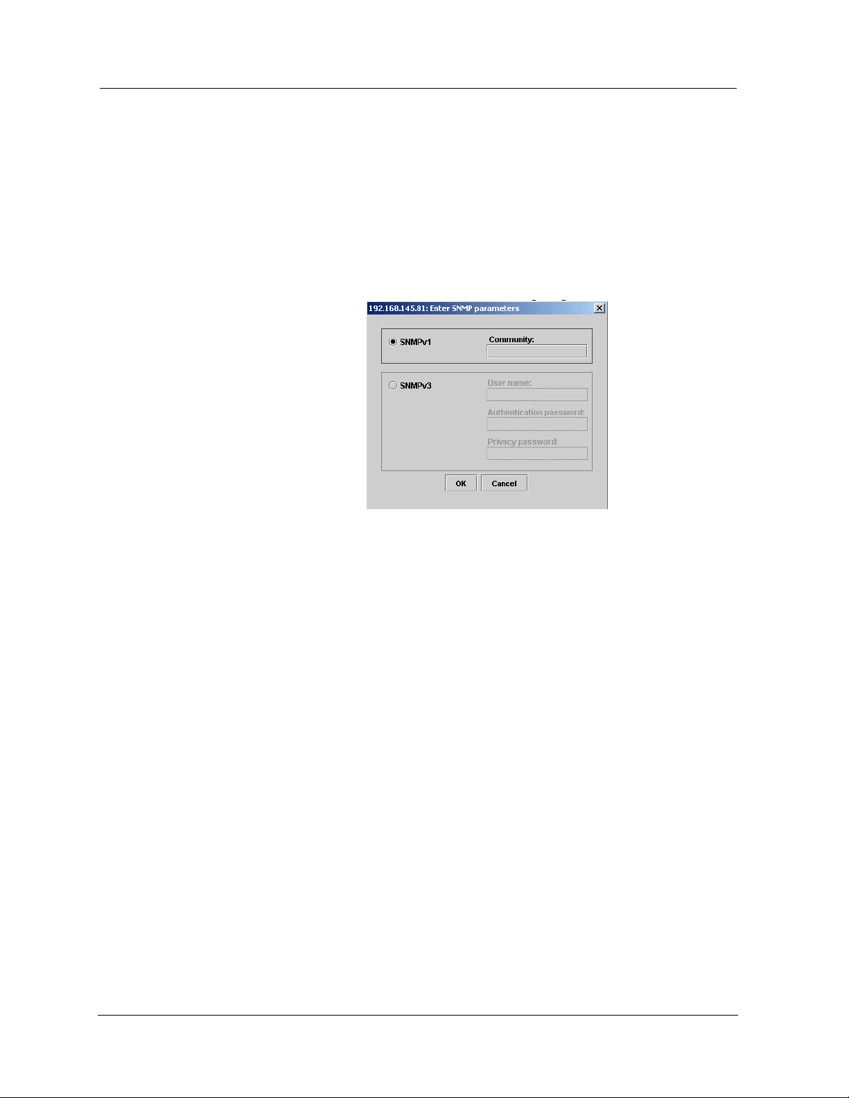
you want to manage. The Network Password dialog box opens.
Figure 1-1. Network Password Dialog Box
Introduction
2. For SNMPv1 login, enter the SNMP community string.
Or
For SNMP v3 login:
Enter the User Name.
Enter the Authentication password.
Enter the Privacy password.
3. Click
OK. The Avaya C360 Welcome page opens.
— If the required Java plug-in is installed on your computer, the
Java Plug-in Security Warning dialog box opens after a few
seconds.
— If the required Java plug-in is not installed, the plug-in is
automatically downloaded to your computer. Follow the
instructions on the Avaya C360 Welcome page to install the
plug-in.
Avaya C360 Manager User Guide 3
Page 18

Chapter 1
The User Interface
The Avaya C360 Manager user interface is different for each of its
management applications. However, the following elements of the user
interface are common to all views:
• Application Tabs
- Tabs for accessing the Device Manager,
Routing Manager, and SMON applications for the Avaya C360
Device.
• Application Area
- An area where the selected application
opens.
• Status Line - Displays the communication status between the
Avaya C360 Manager and the Avaya C360 Device.
Figure 1-2. Avaya C360 Manager User Interface
Application
Tabs
Application
Area
Status Line
Application Tabs
You can access the three main components of device management using
the following Application Tabs in the Avaya C360 Manager:
• Device Manager - View the Avaya C360 Device Manager for
device configuration and Port RMON.
• Device SMON - View SMON (Switch Monitoring) information
for the Avaya C360 Device.
• Routing Manager - View the Avaya C360 Routing configuration.
To switch to a different view, click the appropriate Application Ta b. The
selected application opens.
4 Avaya C360 Manager User Guide
Page 19
Status Line
Introduction
* Note: When the Avaya C360 Manager is installed as a standalone
manager and when running the Avaya C360 Manager via
Web Management, the Device SMON and AnyLayer SMON
tabs do not appear.
The Status Line shows the communication status between the application
and the A vaya C360 Device. The Status Line displays a status message and
an appropriate graphic. The table below shows the possible statuses with
their corresponding graphics, and provides an explanation for each status.
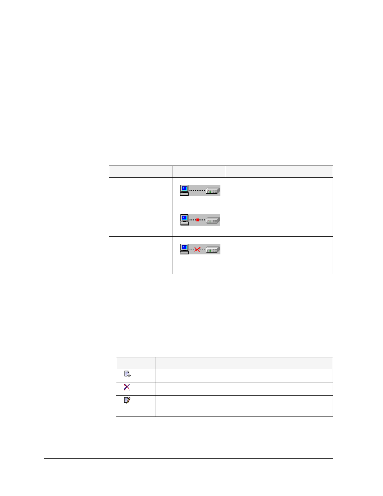
Table 1-1. Communication Statuses
Status Graphic Description
Ready The application is ready to
communicate with the
Avaya C360 Device.
Communicating The application is currently
Communication
Error
Managing Tables
The Avaya C360 Manager interface displays the status of each row in a
table. The following table shows a list of symbols that can appear at the
start of a table row, with their corresponding explanations.
Symbol Explanation
communicating with the
Avaya C360 Device.
The last attempted
communication with the
Avaya C360 Device was not
successful.
Table 1-2. Table Symbols
The row is a new entry.
The row is to be deleted.
The information in the row has been changed by the
user.
To undo all the changes made to a table, click
made to a selected row, click
Apply to update the device.
Avaya C360 Manager User Guide 5
Undo. When all changes are finalized, click
Refresh. To undo changes
Page 20

Chapter 1
6 Avaya C360 Manager User Guide
Page 21

2
Device Manager
This chapter provides an introduction to the Avaya C360 Device
Manager. It includes the following sections:
• The User Interface
Manager user interface, including instructions for selecting
elements and using the toolbar buttons.
• Avaya C360 Device Manager Modes
switching between the configuration and Port RMON modes in
the Avaya C360 Device Manager.
• Refreshing Device Information
refresh the information in the Avaya C360 Manager.
• Using Dialog Boxes and Tables
found in the dialog boxes and tables in the Avaya C360 Device
Manager.
• Using Avaya C360 Device Manager Help
the options for accessing on-line help in the Avaya C360 Device
Manager.
The User Interface
The Avaya C360 Device Manager user interface consists of the following
elements:
- An introduction to the A vaya C360 Device
- Instructions on
- Instructions on how to
- An explanation of the icons
- An explanation of
• Menu Bar - Menus for accessing Avaya C360 Device
management functions.
• Application T oolbar
Device management functions.
• Get/Set Toolbar
configuration of ports and LAGs.
• Tree View
representation of the modules and ports of the Av aya C360
Device.
• Desktop
floating and minimized dialog boxes and tables are displayed.
Avaya C360 Manager User Guide 7
- A resizeable window containing a hierarchical
- A resizeable window where the Chassis View and all
- T oolbar buttons for accessing A vaya C360
- T oolbar buttons for viewing and changing the
Page 22
Chapter 2
• Chassis View - A graphical representation of the Avaya C360
Device.
• Dialog Area - A resizeable window where all dialog boxes and
tables first open.
For information on other parts of the user interface, refer to “
The User
Interface” on page 4.
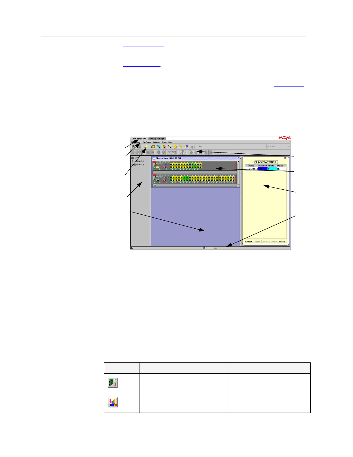
The figure below shows the user interface, with its various parts labeled.
Figure 2-1. The Avaya C360 Device Manager User Interface
Application
Tabs
Menu
Bar
Application
Toolbar
Tree
View
Desktop
Get/Set
Toolbar
Chassis
View
Dialog
Area
Status
Line
To resize the three main areas of the user interface, the Tree View, the
Chassis View, and the Dialog Area, use the splitter bars and their arrows.
Application Toolbar
The Application Toolbar provides shortcuts to the main Device Manager
functions.
The table below describes the buttons on the Application Toolbar and
gives the equivalent menu options.
Table 2-1. Application Toolbar
Button Description Menu Item
Sets the device manager to
Configuration Mode.
Sets the device manager to
Port RMON mode.
8 Avaya C360 Manager User Guide
View > Configuration
View > Port RMON
Page 23
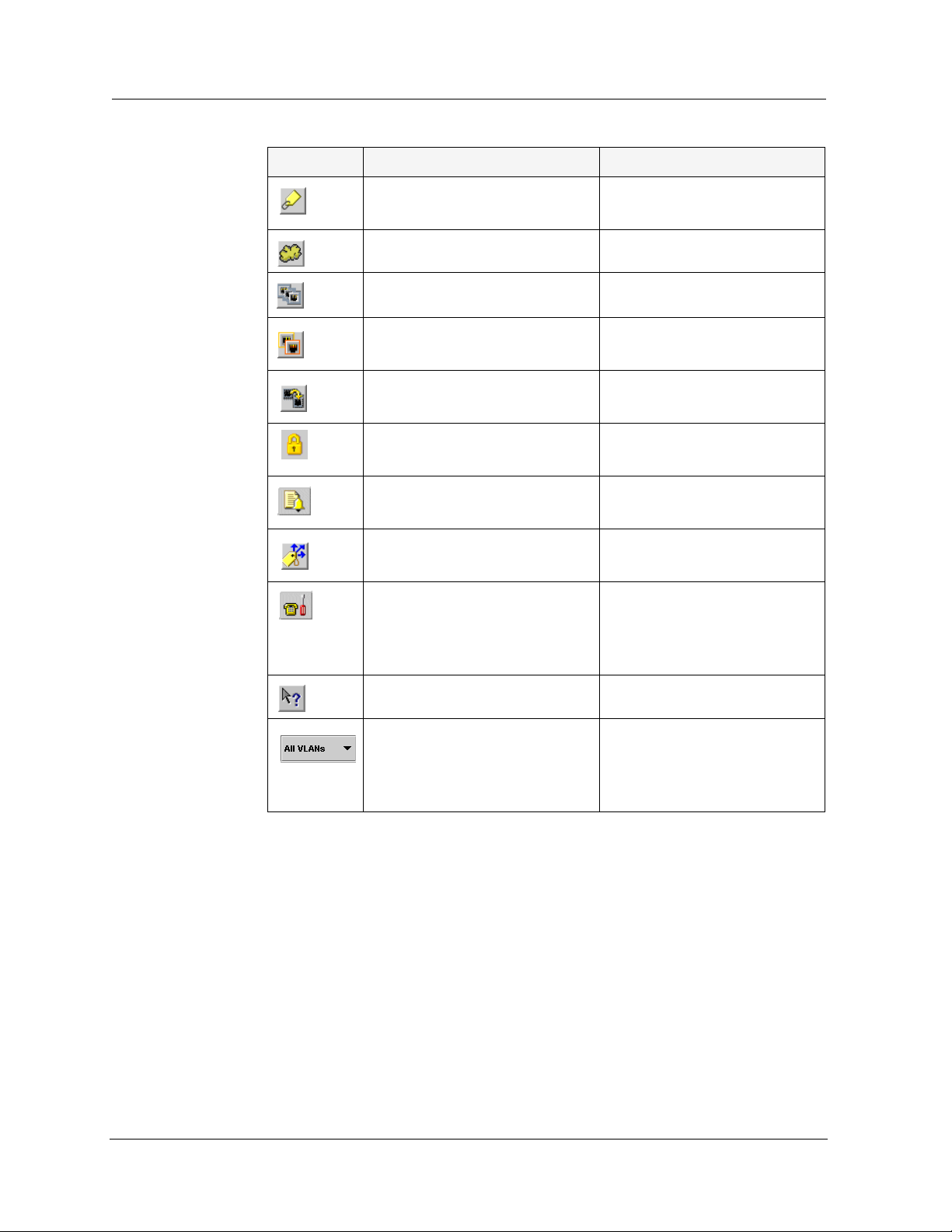
Table 2-1. Application Toolbar (Continued)
Button Description Menu Item
Device Manager
Displays addresses of devices
connected to the switch.
Displays the VLAN window.
Displays the LAG table.
Displays the Port
Redundancy table.
Starts the Port Mirroring
wizard.
Displays the MAC Port
Security configuration.
Displays the Trap Manager
Table.
Displays the IP Multicast
Filtering dialog box.
Launches Avaya Call
Processing on the selected
G700 Media Gateway or
Voice port.
View > Switch Connected
Addresses
Configure > VLAN
Configure > LAG
Configure > Port
Redundancy
Configure > Port Mirroring
Configure > MAC Port
Security
Configure > Trap Managers
Configure > IP Multicast
Filtering
Tools > Administer
Station/Gateway
Opens the on-line help.
Help > Help On
Selects a VLAN. Ports that
are not on the selected
VLAN appear dark gray in
the Chassis View.
When you place the cursor on a toolbar icon for one second, a label
appears with the name of the button.
You can toggle the display of the application toolbar. To toggle the display
of the application toolbar, select
Toolbar
.
View > Toolbars > Show Application
Avaya C360 Manager User Guide 9
Page 24
Chapter 2
Get/Set Toolbar
The Get/Set T oolbar provides butto ns for getting and setting configuration
parameters for selected ports and LAGs. When a port or LAG is selected,
its configuration is reflected on the Get/Set T oolbar . Each group of buttons
represents the various possible states of a configuration parameter. For
example, the first group of buttons represents the possible speed of a
port - 10 Mbps, 100 Mbps, or 1000 Mbps. If the center button is
depressed, the port is currently configured to operate at 100 Mbps.
Selected ports and LAGs can be configured using the Get/Set Toolbar. To
change the configuration of a port or LAG, click the button which
represents the value of the parameter you want to apply to the port or
LAG. Click
discard the changes. Options not applicable to the selected port or LAG
are dimmed.
To configure the ports of a LAG, select the LAG icon in the Tree View or
the Chassis View. Ports belonging to a LAG may not be configured by
selecting the port.
apply to update the device with the changes. Click cancel to
Multiple ports and LAGs can be simultaneously configured using the
Get/Set Toolbar. When multiple ports or LAGs with non-identical
configurations are selected, only the parameters whose settings are
identical on the selected ports or LAGs are reflected in the Get/Set
Toolbar. For example, if a port operating at full duplex and a port
operating at half duplex are selected, neither of the duplex mode buttons
on the Get/Set Toolbar are depressed.
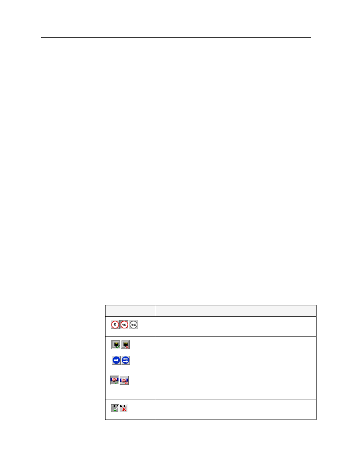
The table below displays the buttons on the Get/Set Toolbar and explains
their functions and settings.
Table 2-2. Get/Set Toolbar
Button Description
Get and set the port/LAG’s speed: 10 Mbps, 100
Mbps, 1000 Mbps.
Get and set the port/LAG’s status: Enabled, Disabled.
Get and set the port/LAG’s mode: Half duplex, Full
duplex.
Get and set the port/LAG’s auto-negotiation status:
Auto-negotiation Enabled, Auto-negotiation
Disabled.
Get and set the port/LAG’s STP mode: Enabled,
Disabled.
10 Avaya C360 Manager User Guide
Page 25
Tree View
Device Manager
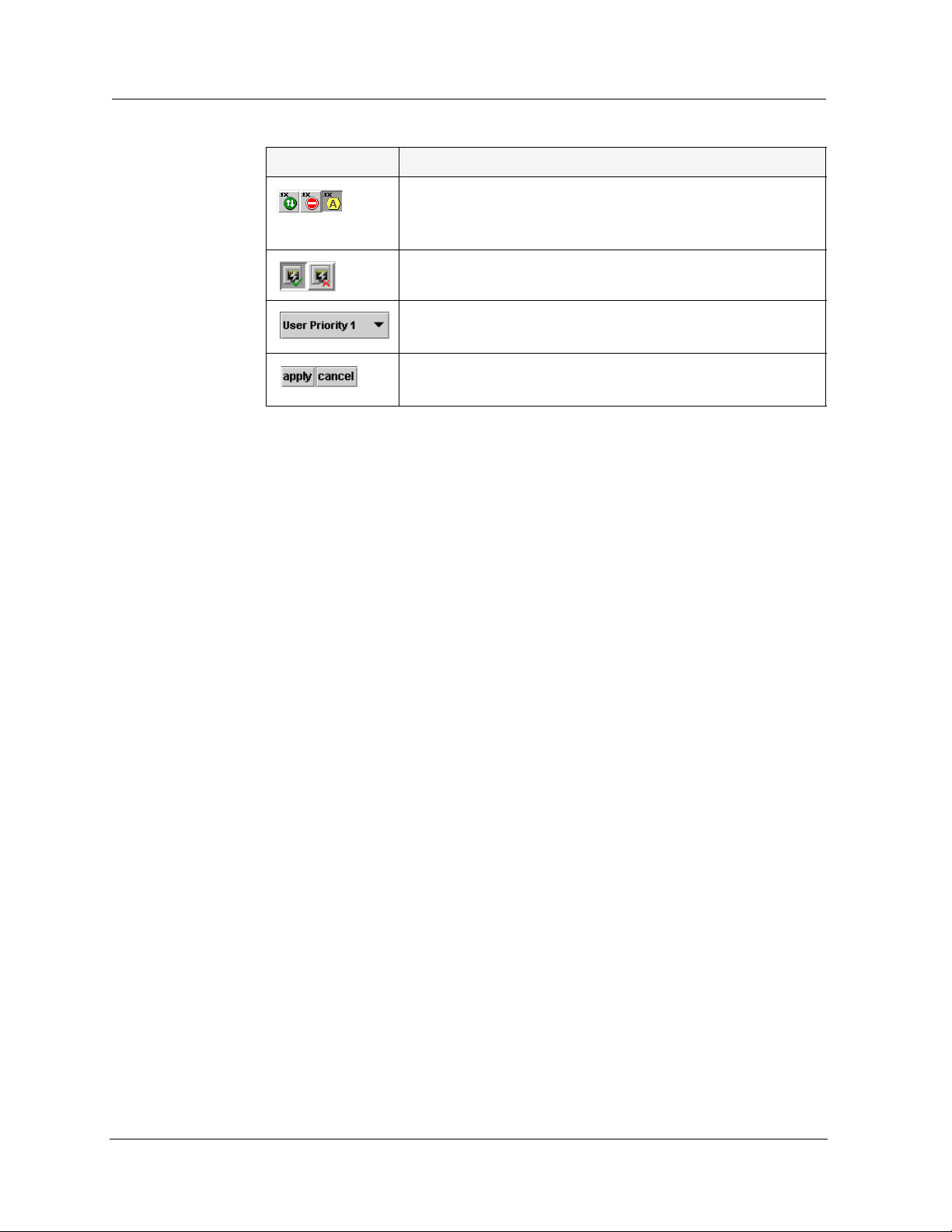
Table 2-2. Get/Set Toolbar (Continued)
Button Description
Get and set the port’s 802.1x mode:
802.1x Force Authorized, 802.1x Force Unauthorized,
802.1x Auto.
Get and set the port’s Power over Ethernet
Get and set the port/LAG’s priority. Select a priority
level between 1 and 8 using the pull-down listbox.
Apply or cancel the configuration changes made with
the Get/Set Toolbar.
You can toggle the display of the Get/Set toolbar. To toggle the display of
the Get/Set toolbar, select
View > Toolbars > Show Get/Set Toolbar.
Desktop
The Tree View shows a hierarchical representation of the structure of the
Avaya C360 Device. To select ports, LAGS, modules or media modules,
click their icons in the Tree View. When an element is selected in the Tree
View, the corresponding element is selected in the Chassis View.
The highest level of the Tree View rep resents th e device. T he se cond level
shows modules. The third level shows ports and LAGs. This includes ports
on expansion modules.
To expand the view of a contracted element in the tree or to contract the
view of an expanded element in the tree:
Double-click the element.
Or
Click the handle next to the element you want to expand or
contract.
The central section of the application window is the Desktop. This area
can be resized by dragging the vertical splitter bars with the mouse.
Floating dialog boxes and tables can be resized. The Chassis View and
floating dialog boxes and tables can also be minimized. Minimized
windows appear at the bottom of the Desktop.
Avaya C360 Manager User Guide 11
Page 26
Chapter 2
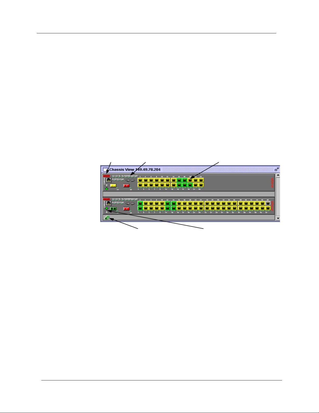
Chassis View
The Chassis View is a graphical representation of the Avaya C360 Device.
The Avaya C360 Device can contain several Avaya C360 modules. The
Chassis View shows all of the device’s modules, LAGs, and ports,
including ports on expansion modules and cascading modules (when
present). The colors of the modules, LAGs, and ports in the Chassis View
reflect their status.
When you hold the cursor over a port’s icon in the Chassis View, a label
appears with the port number, its VLAN ID, and the last fault that
occurred on the port. When you hold the cursor over a LAG’s icon in the
Chassis View, a label appears with the name and VLAN number of the
LAG, and the last fault that occurred on the LAG.
Figure 2-2. Avaya C360 Chassis View
Module Symbol
LEDs
Port Symbols
LAG Sym bol
Cascading Module
Symbols
When viewing selected dialog boxes, the color of the port or LAG
indicates the status of the port or LAG with regard to the application. For
example: When creating a Link Aggregation Group (LAG), ports that can
be selected appear white in the Chassis View. The port selected to be the
base port appears dark blue. The ports selected to be additional ports
appear cyan.
The Cascading Module symbols show the status of the links between
adjacent modules in the device. The Cascading Module symbols at the top
and bottom of the device show the status of the long cable link between
the top and bottom modules in the device. If there is no Cascading
Module in the device, the Cascading Module symbols do not appear.
12 Avaya C360 Manager User Guide
Page 27
Device Manager
The following table provides a list of the possible port and LAG colors in
the Chassis View and their meaning.
Table 2-3. Chassis View Port/LAG Colors
Color Meaning
Green The port/LAG is enabled, and its status is Okay.
Yellow The port/LAG is enabled, and its status is Warning.
Red The port/LAG is enabled, and its status is Fatal.
Light Gray The port/LAG is disabled.
Dark Gray The port/LAG is not associated with the assignment.
White The port/LAG is logically available for assignment.
Dark Blue The port/LAG has been assigned the primary position in
an application.
Cyan The port/LAG has been assigned a secondary position in
an application.
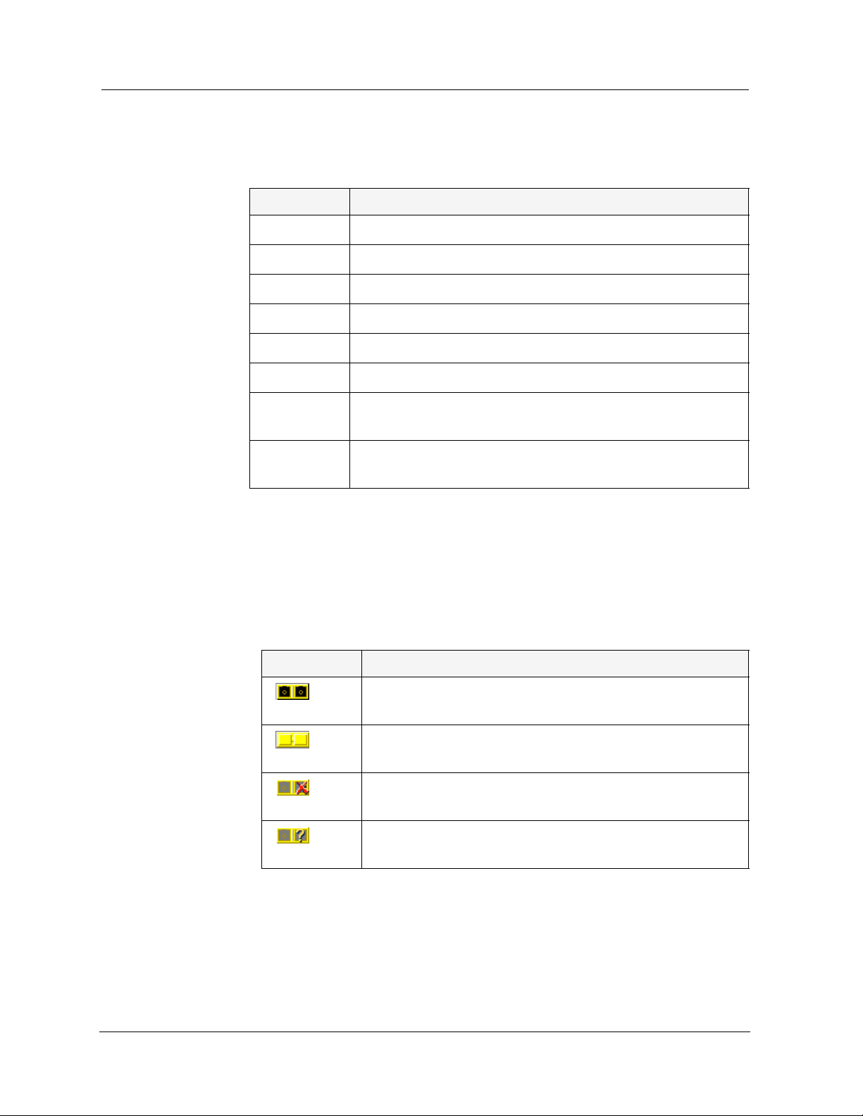
GBIC Ports Some Avaya C360 expansion modules contain GBIC (GigaBit Interface
Converter) ports that house removable transceiver modules. The Chassis
View reflects the management status of the ports. The following table
shows the possible appearances of these ports in the Chassis View and
provides the corresponding management status of the port.
Table 2-4. GBIC Port Status
GBIC Port Status
The GBIC port contains a supported transceiver
module.
There is no transceiver module present in the GBIC
port.
The transceiver module in the GBIC port is not
supported.
The transceiver module in the GBIC port is of an
unknown type.
GBIC ports that contain the following types of transceiver modules can be
configured:
• Supported transceiver modules
• No transceiver modules
• Unknown transceiver modules
Avaya C360 Manager User Guide 13
Page 28

Chapter 2
GBIC ports that contain unsupported transceiver modules cannot be
configured.
Selecting
Elements
You can select modules, LAGs, and ports.
To select a module:
In the Chassis View, click the module’s label.
Or
In the Tree View, click the module’s icon. The module’s label is
highlighted in the Chassis View and the Tree View.
To select a LAG:
In the Chassis View, click the LAG’s icon.
Or
In the Tree View, click the LAG’s icon. The LAG is highlighted in
the Chassis View and the Tree View.
To select a port:
In the Chassis View, click the port.
Or
In the Tree V iew, click the port’s icon. The port is highlighted in the
Chassis View and the Tree View.
— T o select multiple elements, press CTRL while clicking on each
element to be selected.
14 Avaya C360 Manager User Guide
Page 29

Dialog Area
The area to the right of the Chassis View is where all dialog boxes, tables,
and wizards first appear. This area can be resized by dragging the vertical
splitter bar with the mouse. When a dialog box, table, or wizard opens, it
replaces the current dialog box open in the Dialog Area. To view more
than one dialog box or table simultaneously, click the pushpin in the
upper right-hand corner of the dialog box. The dialog box becomes a
floating dialog box and moves to the Desktop.
T o restore a dialog box to the Dialog Area, click the toolbar button or icon
that opened the dialog box. The dialog box returns to the Dialog Area.
Avaya C360 Device Manager Modes
The Avaya C360 Device Manager has two modes:
Device Manager
• Configuration mode
• Port RMON mode
When in configuration mode, you can view and change the configuration
of the Avaya C360 Device and individual ports. When in Port RMON
mode, you can view graphical representations of the traffic on individual
ports.
To switch to configuration mode:
Click .
Or
Select
To switch to Port RMON mode:
Click .
Or
Select
View > Configuration.
View > Port RMON.
Avaya C360 Manager User Guide 15
Page 30

Chapter 2
Refreshing Device Information
You can refresh the information in the Avaya C360 Device Manager. To
refresh Avaya C360 device information, select
A vaya C360 Device Manager refreshes its device information and updates
the display.
Using Dialog Boxes and Tables
Dialog boxes and tables in the Avaya C360 Manager application have a
common set of buttons. The following table displays the buttons and
explains their functions:
Table 2-5. Dialog Box Icons
Icon Function
View > Refresh. The
Refresh
Apply
Insert
Wizard
Delete
Undo
Refreshes the information in the table or dialog box. This
clears any changes made to the table or dialog box and not
yet sent to the device.
Sends the information from the table or dialog box to
update the device.
Adds a row to the table.
Starts a wizard.
Deletes the selected rows of the table.
Undoes all changes to the selected row in a table.
16 Avaya C360 Manager User Guide
Page 31

Using Avaya C360 Device Manager Help
This section explains how to use the on-line help in the Avaya C360
Device Manager. The on-line help can be opened to the contents page or
directly to a topic of interest.
* Note: When running the Avaya C360 Manager via Web
Management, on-line help is only available if you have
installed the on-line help on your network and configured the
Avaya C360 Device with the location of the help files. For
information on installing the on-line help and configuring the
device with the location of the files, refer to the A v aya C36 0
User’s Guide.
Opening the Help to the Contents Page
To open the help to the contents page, select Help > Contents. The on-line
help opens to the contents page.
Device Manager
Opening the Help to a Topic of Interest
To open the help directly to a topic of interest:
1. Click .
Or
Select
shape of an arrow with a question mark.
2. Click on a point of interest in the Avaya C360 Device Manager. The
on-line help opens to a topic explaining the feature that was
clicked.
Help > Context Sensitive Help. The cursor changes to the
Avaya C360 Manager User Guide 17
Page 32

Chapter 2
18 Avaya C360 Manager User Guide
Page 33

3
Device Configuration
This chapter explains how to view and set the various configuration
parameters relevant to the Avaya C360. It includes the following
sections:
• Viewing
about the Avaya C360 Device.
• Viewing
an Avaya C360 module in the device.
• Viewing
LAG on an Avaya C360 module in the device.
• Viewing
ports on the Avaya C360 Device.
• Resetting the Device
To view configuration information, you must be in Configuration mode.
To switch to Configuration mode:
Click .
Or
Select
Device Information- View high-level information
Module Configuration- View information specific to
LAG Configuration- View information specific to a
Port Configuration- View information specific to the
- Reset the Avaya C360 Device.
View > Configuration.
Avaya C360 Manager User Guide 19
Page 34
Chapter 3
Viewing Device Information
The Device Information dialog box provides you with high-level
information specific to the Avaya C360 Device.
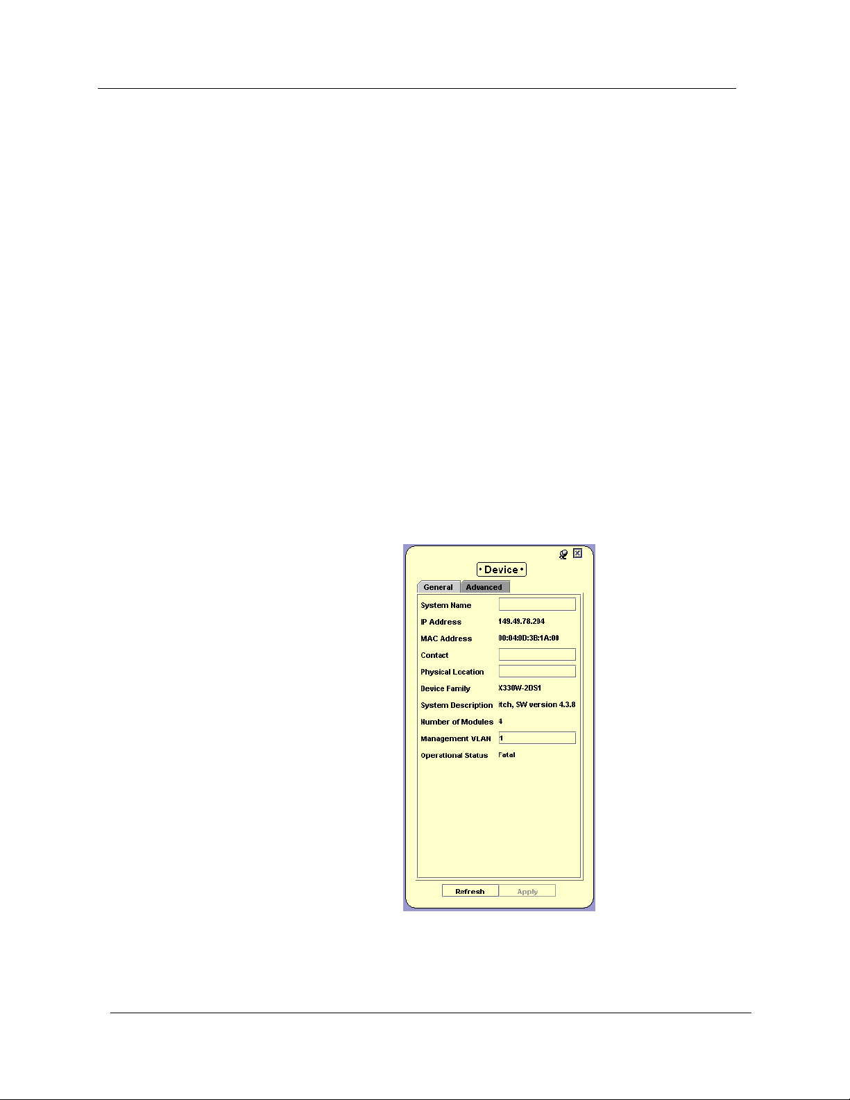
The General tab of the Device Information dialog box provides detailed
information about the device such as the device’s name, addresses,
contact person, location, type, description, the number of modules in the
device, and the management VLAN ID.
The Advanced tab of the Device Information dialog box provides
information about the device’s STP (Spanning Tree Protocol)
configuration.
Device Information - General Tab
To view the General tab of the Device Information dialog box, select
Configure > Device Information. The Device Information dialog box opens
to the General tab.
Figure 3-1. Device Information Dialog Box - General Tab
20 Avaya C360 Manager User Guide
Page 35

Device Configuration
The following table provides a list of the fields in the General tab of the
Device Information dialog box and their descriptions.
Table 3-1. Device Information Fields - General Tab
Field Description
System Name
IP Address
MAC Address
Contact
Physical Location
Device Family
System Description
Number of Modules
Management VLAN
Operational Status
Logical name of the device as defined on the
SNMP agent of the device.
The IP address of the device.
The MAC address of the device.
Individual responsible for maintenance of the
device.
The current physical location of the device.
The family of devices to which the device
belongs.
A description of the device.
The number of modules currently in the
device.
The VLAN ID (VLAN #) of the agent.
The warning level of the device. Possible
values are:
• OK
• Warning
• Fatal
For more information on the user interface, refer to “
Using Dialog Boxes
and Tables” on page 16.
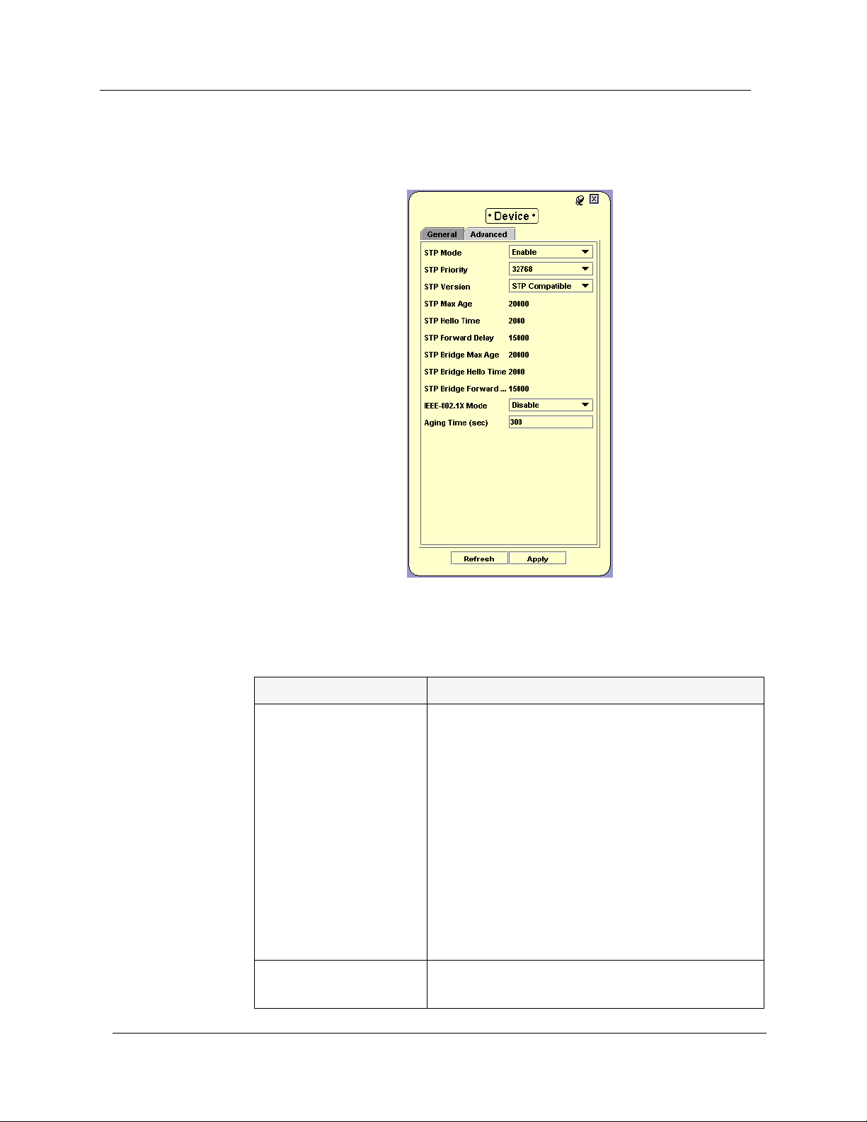
Device Information - Advanced Tab
To view the Advanced tab of the Device Information dialog box:
1. Select
dialog box opens to the General tab.
Avaya C360 Manager User Guide 21
Configure > Device Information. The Device Information
Page 36
Chapter 3
2. Click Advanced. The Advanced tab of the Device Information dialog
box appears.
Figure 3-2. Device Information Dialog Box - Advanced Tab
The following table provides a list of the fields in the Advanced tab of the
Device Information dialog box and their descriptions.
Table 3-2. Device Information Fields - Advanced Tab
Field Description
STP Mode
The state of Spanning Tree Protocol. Possible
states are:
• Disable - STP is disabled. This is the
default state.
• Enable - STP is enabled.
When activating STP, keep in mind that:
• All bridges should run STP.
• Redundancy applications and STP cannot
co-exist.
For more information refer to Spanning Tree
Algorithm (STA) in The Reference Guide.
STP Priority
The priority of the bridge as determined by the
first quarter of the Bridge ID.
22 Avaya C360 Manager User Guide
Page 37

Device Configuration
Table 3-2. Device Information Fields - Advanced Tab (Continued)
Field Description
STP Version
STP Max Age
STP Hello Time
STP Forward Delay
The version of Spanning Tree Protocol to use.
Possible versions include:
• Common Spanning Tree 802.1d - The
standard spanning tree protocol.
• rstp - Rapid spanning tree protocol
802.1w.
The maximum age of Spanning Tree Protocol
information learned from the network on any
port before it is discarded, in milliseconds. This
is the actual value that this device is currently
using.
The amount of time, in milliseconds, between
the transmission of Configuration bridge PDUs
by this node on any port when it is the root of
the spanning tree or trying to become so. This
is the actual value that this device is currently
using.
This speed, in milliseconds, at which a port
changes its spanning state when moving
towards the Forwarding state. The value
determines how long the port stays in each of
the Listening and Learning states, which
precede the Forwarding state. This value is
also used, when a topology change has been
detected and is underway, to age all dynamic
entries in the Forwarding Database.
STP Bridge Max Age The maximum amount of time before
Spanning recalculates if there is no change in
network bridging status.
STP Bridge Hello
Time
The amount of time between sending
Spanning Tree updates if there are no detected
changes in the overall bridged network
topology.
STP Bridge Forward The amount of time for the device to begin
forwarding packets after recalculating its
Spanning Tree table based on a change in
network topology.
Avaya C360 Manager User Guide 23
Page 38

Chapter 3
Table 3-2. Device Information Fields - Advanced Tab (Continued)
Field Description
IEEE-802.1x Mode The status of 802.1x authentication on the
device. Possible values are:
• Enable - Use 802.1x authentication for
connections to this device.
• Disable - Do not require authentication
for connections to this device.
Aging Time (sec) Amount of time MAC addresses remain in the
CAM table.
For more information on the user interface, refer to “Using Dialog Boxes
and Tables” on page 16.
Viewing Module Configuration
The Module Configuration dialog box provides you with information
specific to a selected module.
The General tab of the Module Configuration dialog box provides detailed
information about the module, such as the module’s position in the
device, the module’s type, description, number of ports, mode of
operation, and any faults occurring on the module.
The Advanced tab of the Module Configuration dialog box provides
information about expansion, cascading, LLDP, and BUPS (BackUp Power
Supply) modules that are connected to the selected module.
The Power tab of the Module Configuration dialog box provides
information about the module’ s Power over Ethernet (PoE) configuration.
For more information, refer to Chapter 4,
If you have a G700 Media Gateway Module, the Module Configuration
dialog box includes three additional tabs. For more information, refer to
Chapter 5,
* Note: The information fields in the Module Configuration dialog
G700 Media Gateway.
box vary according to the type of module selected.
Power over Ethernet.
* Note: T o view the configuration of an X330WAN expansion module,
click the expansion module symbol in the Chassis View.
24 Avaya C360 Manager User Guide
Page 39

Module Configuration - General Tab
To view the General tab of the Module Configuration dialog box for a
selected module:
Click the module symbol in the Tree View.
Or
Click the module’s label in the Chassis View. The Module
Configuration dialog box opens to the General tab.
Figure 3-3. Module Configuration Dialog Box - General Tab
Device Configuration
The following table provides a list of the fields in the General tab of the
Module Configuration dialog box and their descriptions:
Table 3-3. Module Configuration Fields - General Tab
Field Description
Module ID
Avaya C360 Manager User Guide 25
The position in which the module is located.
There can be up to 10 modules in a device.
Page 40

Chapter 3
Table 3-3. Module Configuration Fields - General Tab (Continued)
Field Description
Module Type
Module Description
Number of Ports
Software Version
Configuration Symbol
The module type. Possible values include:
• MM710
• MM711
• MM712
• MM714
• MM717
• MM720
• MM722
• MM760
• S8300
A description of the module type.
The number of ports located on the module.
The version of the application software
running on the module.
The version of the module. The version is
updated whenever there is a functional
modification to the module.
Serial Number
Expansion Type
Expansion Description
Expansion CS
Cascading Type
Cascading CS
A unique number assigned by Avaya Inc. to
the selected module.
The type of expansion module in the selected
module.
A description of the expansion module in the
selected module.
The version of the expansion module. The
version is updated whenever there is a
functional modification to the module.
The type of cascading module in the selected
module. The cascading module is needed to
connect modules in the device.
The version of the cascading module. The
version is updated whenever there is a
functional modification to the module.
26 Avaya C360 Manager User Guide
Page 41

Device Configuration
Table 3-3. Module Configuration Fields - General Tab (Continued)
Field Description
Route Mode The routing mode configured on a C360R
module. Routing modes include:
• Second Layer - The router module
performs as a second layer module and
performs no routing functions.
• Router - The router module performs
full routing functions.
Operational Status
The warning level of the module. Possible
values are:
• OK
• Warning
• Fatal
Fault Messages
A list of fault messages.
* Note: Media Modules cannot be inserted into the C360.
Rather, they have to be inserted into G700, which is
then stacked with the C360.
For more information on the user interface, refer to “
and Tables” on page 16.
Using Dialog Boxes
Avaya C360 Manager User Guide 27
Page 42

Chapter 3
Module Configuration - Advanced Tab
To view the Advanced tab of the Module Configuration dialog box for a
selected module:
1. Click the module symbol in the Tree View.
Or
Click the module’s label in the Chassis View. The Module
Configuration dialog box opens to the General tab.
2. Click
Figure 3-4. Module Configuration Dialog Box - Advanced Tab
Advanced. The Advanced tab of the Module Configuration
dialog box appears.
28 Avaya C360 Manager User Guide
Page 43

Device Configuration
The following table provides a list of the fields in the Advanced tab of the
Module Configuration dialog box and their descriptions:
Table 3-4. Module Configuration Fields - Advanced Tab
Field Description
BUPS Module Type
BUPS Module CS
Cascading Up Mon.
Cascade Down Mon.
The type of BUPS (BackUp Power Supply)
module in the selected module.
The version of the BUPS (BackUp Power
Supply) module. The version is updated
whenever there is a functional modification to
the module.
Determines if the devices in the system are
monitored cascading up. The possible values
are:
• Enable - Monitors devices in the
network cascading up. If the connection
is lost, the system reports a error.
• Disable - Does not monitor devices in
the network cascading up. If the
connection is lost, the system does not
report a error.
Determines if the devices in the system are
monitored cascading down. The possible
values are:
• Enable - Monitors devices in the
network cascading down. If the
connection is lost, the system reports a
error.
• Disable - Does not monitor devices in
the network cascading down. If the
connection is lost, the system does not
report a error.
Internal PS Status The operating status of the primary power
supply.
BUPS Status The operating status of the BUPS.
LLDP Mode
The status of Link Layer Discovery Protocol
(LLDP) Mode on the device:
• Enable - Use LLDP Mode.
• Disable - Do not use LLDP Mode.
LLDP Tx Interval
The amount of time between packet
transmissions on the device.
Avaya C360 Manager User Guide 29
Page 44

Chapter 3
Table 3-4. Module Configuration Fields - Advanced Tab (Continued)
Field Description
LLDP Tx Hold Multiplier
The LLDP time-to-live value expressed as a
multiple of the value configured in the
LLDP Tx Interval field.
LLDP Tx Delay
The delay between successive LLDP frame
transmissions initiated by status changes in
LLDP.
LLDP Re-Init Delay
The amount of time the device is instructed to
wait before re-initiating LLDP.
For more information on the user interface, refer to “Using Dialog Boxes
and Tables” on page 16.
30 Avaya C360 Manager User Guide
Page 45

Viewing LAG Configuration
The LAG Configuration dialog box provides you with information specific
to a selected LAG.
The General tab of the LAG Configuration dialog box provides detailed
information about the LAG, such as the LAG’s status, name, VLAN
tagging mode, VLAN ID, priority level, and mode of operation.
The Advanced tab of the LAG Configuration dialog box provides
information about the LAG’s STP configuration.
The Get/Set Toolbar provides an alternative, quick method to view and
change a LAG’s configuration. For more information on the Get/Set
Toolbar, refer to “
Get/Set Toolbar” on page 10.
Device Configuration
Avaya C360 Manager User Guide 31
Page 46

Chapter 3
LAG Configuration - General Tab
To view the General tab of the LAG Configuration dialog box for a
selected LAG:
Click the LAG’s symbol in the Tree View.
Or
Click the LAG’s icon in the Chassis View. The LAG Configuration
dialog box opens to the General tab.
Figure 3-5. LAG Configuration Dialog Box - General Tab
The following table provides a list of the fields in the General tab of the
LAG Configuration dialog box and their descriptions:
Table 3-5. LAG Configuration Fields - General Tab
Field Description
Port Type
Port Functionality
The type of ports in the selected LAG.
The physical media type of the ports of the
selected LAG. If the port conforms to a certain
standard (Repeater, Transceiver, 10BaseT,
etc.), this standard is displayed. If the port
does not conform to any standard, Private is
displayed.
32 Avaya C360 Manager User Guide
Page 47

Device Configuration
Table 3-5. LAG Configuration Fields - General Tab (Continued)
Field Description
Administrative Status
LAG Name
Tagging Mode
VLAN ID
Priority Level
The administrative state of the selected LAG:
• Enabled - The LAG is enabled and can
transmit and receive packets.
•
Disabled - The LAG is disabled and
cannot transmit or receive packets.
The name of the LAG.
The LAG’s operation mode regarding VLANs.
The possible modes are:
• Clear - Transmits each outgoing packet
in untagged format if it belongs to the
LAG’s VLAN. Otherwise, it discards the
packet.
• IEEE-802.1Q - VLAN tagging, per IEEE
802.1Q VLAN standard. The LAG will
transmit frames with a VLAN ID of 1 -
3071.
The VLAN number of the LAG.
The priority level of packets exiting the LAG.
For effective transmission, multimedia packets
must be received isochronously (at regular
intervals). To ensure this, you can assign
priorities to packets coming out of a LAG.
Whenever traffic load is extreme and a LAG
cannot accept all incoming packets, packets
sent from a LAG with the highest priority will
pass through first. However, a fairness
mechanism will allow low priority packets to
eventually enter the bus.
Possible values are User Priority 0 .. User
Priority 7.
Avaya C360 Manager User Guide 33
Page 48

Chapter 3
Table 3-5. LAG Configuration Fields - General Tab (Continued)
Field Description
Auto Negotiation
Mode
The configured state of the Auto-Negotiation
protocol between two stations. When enabled,
Auto-Negotiation detects the highest common
denominator for communication between
endstations, and sets both to the same highest
common setting. It also delivers remote link
status.
For LAGs with 10BaseT and 100BaseT ports,
Auto-Negotiation determines the speed and
Duplex Mode of communication between the
endstations. For LAGs with Gigabit ports,
Auto-Negotiation determines the Flow
Control setting of the ports.
Possible values are:
• Enable - Auto-Negotiation is enabled for
this LAG.
• Disable - Auto-Neotiation is not enabled
for this LAG.
For more information, refer to Auto-Negotiation
in The Reference Guide.
Duplex Mode
Speed Mode
Flow Control Mode
The state of communication of the selected
LAG. Possible values are:
• Full Duplex - The LAG can send and
receive simultaneously.
• Half Duplex - The LAG can either
receive or send, but can not do both
simultaneously.
The speed of communication of the ports on
the selected LAG. Possible values are:
• Ethernet - 10 Mbps.
• Fast Ethernet - 100 Mbps.
• Gigabit Ethernet - 1000 Mbps.
The state of flow control on the selected LAG.
Possible values are:
• No Flow Control
• 802.3x Sym
34 Avaya C360 Manager User Guide
Page 49

Device Configuration
Table 3-5. LAG Configuration Fields - General Tab (Continued)
Field Description
Operational Status
The warning level of the ports on the selected
LAG. Possible values are:
• OK
• Warning
• Fatal
Fault Messages
A list of fault messages.
For more information on the user interface, refer to “Using Dialog Boxes
and Tables” on page 16.
LAG Configuration - Advanced Tab
To view the Advanced tab of the LAG Configuration dialog box for a
selected LAG:
1. Click the LAG’s symbol in the Tree View.
Or
Click the LAG’s icon in the Chassis View. The LAG Configuration
dialog box opens to the General tab.
Avaya C360 Manager User Guide 35
Page 50

Chapter 3
2. Click Advanced. The Advanced tab of th e LAG Configuration dialog
box appears.
Figure 3-6. LAG Configuration Dialog Box - Advanced Tab
The following table provides a list of the fields in the Advanced tab of the
LAG Configuration dialog box and their descriptions:
Table 3-6. LAG Configuration Fields - Advanced Tab
Field Description
Flow Control
Advertisement
The flow control values advertised by the
LAGs on the selected LAG. These values limit
the flow control possibilities to be decided by
Auto-Negotiation.
36 Avaya C360 Manager User Guide
Page 51

Device Configuration
Table 3-6. LAG Configuration Fields - Advanced Tab (Continued)
Field Description
LAG STP Mode
Enables LAG Spanning Tree. The Spanning
Tree mode creates a logical tree topology out
of any arrangement of bridges, resulting in a
single path between any two end stations. The
Spanning Tree Mode also provides high fault
tolerance. The possible states are:
• Enable - Enables the Spanning Tree
Mode.
• Disable - Disables the Spanning Tree
Mode.
For more information refer to Spanning Tree
Algorithm (STA) in The Reference Guide.
LAG STP State The state of the LAG in terms of the Spanning
Tree Protocol. The possible states are:
• Disable - The LAG is disabled.
• Blocking - STP is enabled and currently
blocking the LAG. The LAG is effectively
disabled to prevent the formation of a
loop in the network.
• Forwarding - The LAG is currently
forwarding information received.
STP Admin Edge
STP Oper Edge
The administrative state of the edge LAG
parameter. Possible states include:
• TRUE - This LAG is assumed to be an
edge LAG.
• FALSE - This LAG is assumed not to be
an edge-LAG.
The operational state of the edge LAG
parameter.
• TRUE - This LAG is operating in the
state specified in STP Admin Edge.
• FALSE - A BPDU was received by the
LAG.
Avaya C360 Manager User Guide 37
Page 52

Chapter 3
Table 3-6. LAG Configuration Fields - Advanced Tab (Continued)
Field Description
STP Admin P2P
STP Oper P2P
The administrative point-to-point status of the
LAN segment attached to this LAG. Possible
statuses include:
• True - The LAG should always be treated
as if it is connected to a point-to-point
link.
• forceFalse - The LAG should be treated
as having a shared media connection.
• auto - The LAG is considered to have a
point-to-point link if it is an Aggregator
and all of its members are aggregative, or
if the MAC entity is configured for full
duplex operation, either through
auto-negotiation or by management
means.
The operational point-to-point status of the
LAN segment attached to this LAG. It
indicates whether a LAG is considered to have
a point-to-point connection or not.
The value is determined by STP Admin P2P.
STP Admin Path Cost
STP Path Cost
STP Force Migration
The administratively assigned value for the
contribution of this LAG to the path cost of
paths towards the spanning tree root. A value
of 0 assigns the automatically calculated
default Path Cost value to the LAG.
STP Admin Path Cost complements STP Path
Cost, which returns the operational value of
the path cost.
The operational cost factor used by Spanning
Tree Algorithm to determine the most efficient
route for forwarding traffic to its destination
while removing loops in the network.
For more information refer to Spanning Tree
Algorithm (STA) in The Reference Guide.
When checked and in RSTP mode, the LAG is
forced to transmit RSTP BPDUs.
38 Avaya C360 Manager User Guide
Page 53

Device Configuration
Table 3-6. LAG Configuration Fields - Advanced Tab (Continued)
Field Description
Port Classification
For more information on the user interface, refer to “Using Dialog Boxes
and Tables” on page 16.
The classification of a specific LAG. Port
Classification allows network managers to
specify each LAG level’s importance. The
possible states are:
•
•
For more information refer to Port Classification
in The Reference Guide.
Viewing Port Configuration
The Port Configuration dialog box contains tabs that provide you with
information specific to a selected port.
The General tab of the Port Configuration dialog box provides detailed
information about the port, such as the port name, type, functionality,
status, VLAN ID, mode of operation, and any faults occurring on the port.
Regular - Normal users.
Valuable - Servers or critical users.
The Advanced tab of the Port Configuration dialog box provides detailed
information about the port’s STP configuration and port classification.
The 802.1x tab of the Port Configuration dialog box provides detailed
information about the port’s 802.1x configuration. For more information
about 802.1x security, refer to Chapter 16,
The Power tab of the Port Configuration dialog box provides information
about the port’s Po E configuration. For more information about PoE, refer
to Chapter 4,
The LLDP tab of the Port Configuration dialog box provides configuration
information for the Link Layer Display Protocol on the port.
The Get/Set Toolbar provides an alternative, quick method to view and
change the port’s configuration. For more information on the Get/Set
Toolbar, refer to “
* Note: The configuration of ports that participate in a LAG cannot be
Power over Ethernet.
Get/Set Toolbar” on page 10.
changed using the Port Configuration dialog box. Use the LAG
Configuration dialog box instead.
Port Security.
Avaya C360 Manager User Guide 39
Page 54
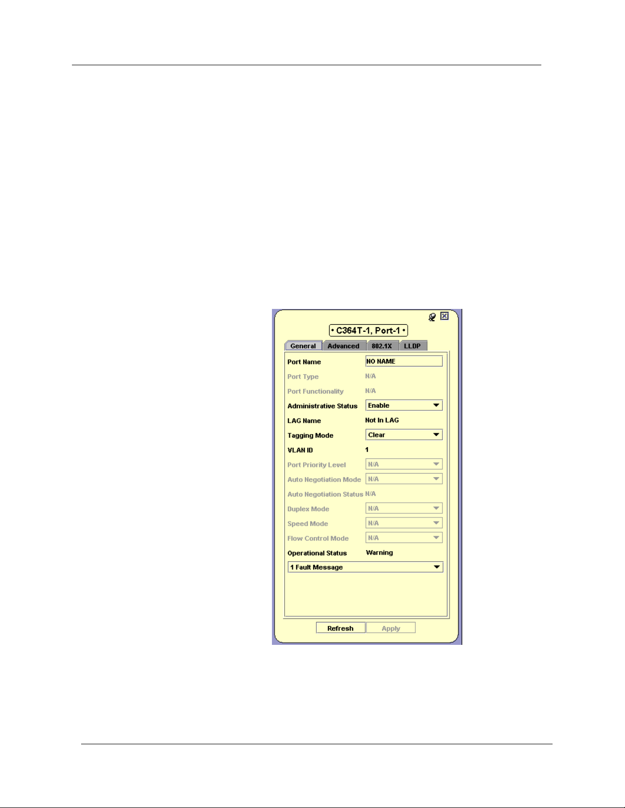
Chapter 3
* Note: The information fields in the Port Configuration dialog box
vary according to the type of port selected.
Port Configuration - General Tab
T o view the General tab of the Port Configuration dialog box for a se lected
port:
Click the port symbol in the Chassis View.
Or
Click the port’s icon in the Tree View. The Port Configuration
dialog box opens to the General tab.
Figure 3-7. Port Configuration Dialog Box - General Tab
40 Avaya C360 Manager User Guide
Page 55

Device Configuration
The following table provides a list of the fields in the General tab of the
Port Configuration dialog box and their descriptions:
Table 3-7. Port Configuration Fields - General Tab
Field Description
Port Name
Port Type
Port Functionality
Administrative Status
LAG Name
Tagging Mode
The user can define a logical name to the port
for ease of use.
The port type; optionally includes reference to
the module to which it is attached and port
connector type.
The physical media type of the selected port. If
the port conforms to a certain standard
(Repeater, Transceiver, 10BaseT, etc.), this
standard is displayed. If the port does not
conform to any standard, Private is displayed.
The administrative state of the selected port:
• Enabled - The port is enabled and can
transmit and receive packets.
• Disabled - The port is disabled and
cannot transmit or receive packets.
The name of the LAG of which the port is a
member. If the port is not a member of a LAG,
the LAG Name is not in LAG.
The port’s operation mode regarding VLANs.
The possible modes are:
• Clear - Transmits each outgoing packet
in untagged format if it belongs to the
port’s VLAN. Otherwise, it discards the
packet.
• 802.1Q - VLAN tagging, per IEEE 802.1Q
VLAN standard. The port will transmit
frames with a VLAN ID of 1 - 3071.
VLAN ID
Avaya C360 Manager User Guide 41
The VLAN number of the port.
Page 56

Chapter 3
Table 3-7. Port Configuration Fields - General Tab (Continued)
Field Description
Port Priority Level
Auto Negotiation
Mode
The priority level of packets exiting the port or
ports on the module. For effective
transmission, multimedia packets must be
received isochronously (at regular intervals).
To ensure this, you can assign priorities to
packets coming out of a port.
Whenever traffic load is extreme and a port
cannot accept all incoming packets, packets
sent from a port with the highest priority will
pass through first. However, a fairness
mechanism will allow low priority packets to
eventually enter the bus.
Possible values are User Priority 0 .. User
Priority 7.
The configured state of the Auto-Negotiation
protocol between two stations. When enabled,
Auto-Negotiation detects the highest common
denominator for communication between
endstations, and sets both to the same highest
common setting. It also delivers remote link
status.
For 10BaseT and 100BaseT ports,
Auto-Negotiation determines the speed and
Duplex Mode of communication between the
endstations. For Gigabit ports, AutoNegotiation determines the Flow Control
setting of the ports.
Possible values are:
• Enable - Auto-Negotiation is enabled on
this port.
• Disable - Auto-Negotiation is not
enabled on this port.
For more information, refer to Auto-Negotiation
in The Reference Guide.
42 Avaya C360 Manager User Guide
Page 57

Device Configuration
Table 3-7. Port Configuration Fields - General Tab (Continued)
Field Description
Auto Negotiation
Status
Duplex Mode
The operational state of the Auto-Negotiation
protocol between two stations. Possible
statuses are:
• Pass - The Auto-Negotiation protocol is
enabled and a common protocol has
been established.
• In progress - The Auto-Negotiation
protocol is in the process of detecting the
communication capabilities of the
endstations and setting them to the
highest common denominator.
• Fail - The Auto-Negotiation protocol
was not able to detect the
communication capabilities of the end
station, or was unable to set them to the
highest common denominator.
• Disabled - The Auto-Negotiation
protocol is disabled.
The state of communication of the selected
port. Possible values are:
Speed Mode
Flow Control Mode
Operational Status
Fault Messages
• Full Duplex - The port can send and
receive simultaneously.
• Half Duplex - The port can either
receive or send, but can not do both
simultaneously.
The speed of communication of the selected
port. Possible values are:
• Ethernet - 10 Mbps.
• Fast Ethernet - 100 Mbps.
• Gigabit Ethernet - 1000 Mbps.
The state of flow control on the selected port.
The warning level of the selected port.
Possible values are:
• OK
• Warning
• Fatal
A list of fault messages.
Avaya C360 Manager User Guide 43
Page 58

Chapter 3
For more information on the user interface, refer to “Using Dialog Boxes
and Tables” on page 16.
Port Configuration - Advanced Tab
To view the Advanced tab of the Port Configuration dialog box for a
selected port:
1. Click the port symbol in the Chassis View.
Or
Click the port’s icon in the Tree View. The Port Configuration
dialog box opens to the General tab.
2. Click
Advanced. The Advanced tab of the Port Configuration dialog
box appears.
Figure 3-8. Port Configuration Dialog Box - Advanced Tab
44 Avaya C360 Manager User Guide
Page 59

Device Configuration
The following table provides a list of the fields in the Advanced tab of the
Port Configuration dialog box and their descriptions:
Table 3-8. Port Configuration Fields - Advanced Tab
Field Description
Port STP Mode
Enables Port Spanning Tree. The Spanning
Tree mode creates a logical tree topology out
of any arrangement of bridges, resulting in a
single path between any two end stations. The
Spanning Tree Mode also provides high fault
tolerance. The possible states are:
• Enable - Enables the Spanning Tree
Mode.
• Disable - Disables the Spanning Tree
Mode.
For more information refer to Spanning Tree
Algorithm (STA) in The Reference Guide.
Port STP State The state of the port in terms of the Spanning
Tree Protocol. The possible states are:
• Disable - The port is disabled.
• Blocking - STP is enabled and currently
blocking the port. The port is effectively
disabled to prevent the formation of a
loop in the network.
• Forwarding - The port is currently
forwarding information received.
STP Admin Edge
The administrative state of the edge port
parameter. Possible states include:
• TRUE - This port is assumed to be an
edge port.
• FALSE - This port is assumed not to be
an edge-port.
STP Oper Edge
The operational state of the edge port
parameter.
• TRUE - This port is operating in the state
specified in STP Admin Edge.
• FALSE - A BPDU was received by the
port.
Avaya C360 Manager User Guide 45
Page 60

Chapter 3
Table 3-8. Port Configuration Fields - Advanced Tab (Continued)
Field Description
STP Admin P2P
STP Oper P2P
The administrative point-to-point status of the
LAN segment attached to this port. Possible
statuses include:
• True - The port should always be treated
as if it is connected to a point-to-point
link.
• forceFalse - The port should be treated
as having a shared media connection.
• auto - The port is considered to have a
point-to-point link if it is an Aggregator
and all of its members are aggregative, or
if the MAC entity is configured for full
duplex operation, either through
auto-negotiation or by management
means.
The operational point-to-point status of the
LAN segment attached to this port. It indicates
whether a port is considered to have a
point-to-point connection or not.
The value is determined by STP Admin P2P.
STP Admin Path Cost
The administratively assigned value for the
contribution of this port to the path cost of
paths towards the spanning tree root. A value
of 0 assigns the automatically calculated
default Path Cost value to the port.
STP Admin Path Cost complements STP Path
Cost, which returns the operational value of
the path cost.
STP Path Cost
The operational cost factor used by Spanning
Tree Algorithm to determine the most efficient
route for forwarding traffic to its destination
while removing loops in the network.
For more information refer to Spanning Tree
Algorithm (STA) in The Reference Guide.
STP Priority The priority factor used by STP to determine
the activity status of an individual port on the
Spanning Tree.
STP Force Migration
When checked and in RSTP mode, the port is
forced to transmit RSTP BPDUs.
46 Avaya C360 Manager User Guide
Page 61

Device Configuration
Table 3-8. Port Configuration Fields - Advanced Tab (Continued)
Field Description
Port Classification
The classification of a specific port. Port
Classification allows network managers to
specify each port level’s importance. The
possible states are:
• Regular - Normal users.
• Valuable - Servers or critical users.
For more information refer to Port Classification
in The Reference Guide.
For more information on the user interface, refer to “Using Dialog Boxes
and Tables” on page 16.
Avaya C360 Manager User Guide 47
Page 62

Chapter 3
Port Configuration - LLDP Tab
Link Layer Discovery Protocol (LLDP) is a neighbor discovery protocol,
which allows Ethernet network devices to search for, and request
information from, other LLDP enabled devices on the network. LLDP
defines a standard method for Ethernet network devices, such as
switches, routers, and wireless LAN access points, to advertise
information about themselves to other nodes on the network.
LLDP also allows Ethernet network devices to search for, and request
information from, other devices using the LLDP protocol.
The following details can be advertised using LLDP on the Avaya C360
device:
• System Name
• Chassis ID
• Port ID
• System Description
• System Capabilities
• Port Description
• Management Address
* Note: Chassis ID and Port ID are always advertised when
LLDP is enabled.
48 Avaya C360 Manager User Guide
Page 63

Device Configuration
To view the LLDP tab of the Port Configuration dialog box for a selected
port:
1. Click the port symbol in the Chassis View.
Or
Click the port’s icon in the Tree View. The Port Configuration
dialog box opens to the General tab.
2. Click the
LLDP tab. The Port Configuration Dialog Box - LLDP Tab
opens.
Figure 3-9. Port Configuration Dialog Box - LLDP Tab
Avaya C360 Manager User Guide 49
Page 64

Chapter 3
The following table provides a list of the fields in the LLDP tab of the Port
Configuration dialog box and their descriptions:
Table 3-9. Port Configuration Fields - LLDP Tab
Field Description
LLDP Admin Status
LLDP TLVs
Transmission
The status of LLDP mode on the device.
Possible values are:
• Tx Only - LLDP mode is enabled, and is
configured to only accept Tx traffic.
• Rx Only - LLDP mode is enabled, and is
configured to only accept Rx traffic.
• Tx and Rx - LLDP mode is enabled, and
is configured to accept both Tx and Rx
traffic.
• Disabled - LLDP mode is disabled.
• N/A - LLDP mode is not supported for
this port.
The optional type length values advertised by
the device. Possible values include:
• System Name.
• System Description.
• System Capabilities.
• Port Description.
• Management Address.
Selecting the checkbox instructs the device to
advertise the indicated TLV. Leaving the
checkbox blank instructs the device not to
display the indicated TLV.
Chassis ID and Port ID are not displayed as
advertising their values is mandatory when
LLDP is enabled.
50 Avaya C360 Manager User Guide
Page 65

Resetting the Device
You can reset the entire Avaya C360 Device, or one or more of its
individual modules.
To reset the entire Avaya C360 Device:
Device Configuration
1. Select
2. Click
Action > Reset Device. A confirmation dialog box opens.
Yes. The device resets.
To reset an individual Avaya C360 module:
1. Click the label of the module you want to reset.
— To select multiple modules, press CTRL while clicking
additional module labels.
2. Select
3. Click
Actions > Reset Module(s). A confirmation dialog box opens.
Yes. The selected module resets.
To reset an individual G700 Media Module:
1. Click the label of the G700 Media Module you want to reset.
— To select multiple modules, press CTRL while clicking
additional module labels.
2. Select
Actions > Reset Media Module(s). A confirmation dialog box
opens.
3. Click
Yes. The selected module resets.
To reset an individual Avaya X330WAN module:
1. Click the label of the X330WAN module you want to reset.
— To select multiple modules, press CTRL while clicking
additional module labels.
2. Select
Actions > Reset WAN Plugin(s). A confirmation dialog box
opens.
3. Click
Avaya C360 Manager User Guide 51
Yes. The selected module resets.
Page 66

Chapter 3
52 Avaya C360 Manager User Guide
Page 67

4
Power over Ethernet
This chapter provides information about Power over Ethernet (PoE) and
includes the following sections:
• PoE Overview
• Viewing PoE Information
PoE Overview
PoE provides power to IP telephones over an Ethernet line using an
A vaya C360 device. The power is transmitted via the device’s po rts to the
IP telephones over the same cable carrying IP packets.
The Avaya C360 device automatically discovers the connection and
removal of IP telephones from the in-line powered ports and provides
power accordingly.
The Avaya C360 provides the power using an internal 225 watt power
supply over a 48 volt feed. It is possible to attach an external power
supply either for additional power, or as an alternative power supply
should the internal power supply fail.
- An overview of Power over Ethernet
functionality in Avaya C360 devices.
- Information about viewing PoE
port information and configuring PoE on a module and port level.
In addition, you can configure power priorities per port ensuring that
important equipment is guaranteed power whenever necessary.
Avaya C360 Manager User Guide 53
Page 68

Chapter 4
Viewing PoE Information
This section provides information about viewing port information and
configuring PoE on the port and module level, and includes the following:
• Viewing PoE Port Information
• Viewing PoE Configuration
Viewing PoE Port Information
The Chassis View provides immediate information about PoE. Ports that
are currently supplying power to IP telephones are labeled with a
lightning bolt.
Viewing PoE Configuration
You can view PoE configuration information on the module and port
levels.
54 Avaya C360 Manager User Guide
Page 69

Power over Ethernet
PoE Module
Configuration
To view the PoE configuration on a module that supports PoE, select the
Power tab in the module’s configuration dialog box. For information on
opening the Module Configuration dialog box, refer to “
Viewing Module
Configuration” on page 24.
Figure 4-1. Module Configuration - Power Tab
The following table provides a list of the fields in the Power tab of the
Module Configuration dialog box and their descriptions:
Table 4-1. Module Configuration - Power Fields
Field Description
PoE Power
Consumption [W]
Internal PS PoE
Allocation[W}
The current power consumption of the
devices attached to the module.
The total available power output that can be
allocated by the module’s internal power
supply (in Watts).
PoE Power Threshold
[%]
Avaya C360 Manager User Guide 55
The percentage of available allocated power
being used by the module.
Page 70

Chapter 4
PoE Port
Configuration
To view the PoE configuration on a port that supports PoE, select the
Power tab in the port’s configuration dialog box. For more information on
opening the Port Configuration dialog box, refer to “
Configuration” on page 39.
Figure 4-2. Port Configuration - Power Tab
Viewing Port
The following table provides a list of the fields in the Power tab of the
Module Configuration dialog box and their descriptions:
Table 4-2. Port Configuration - Power Fields
Field Description
Administrative Status
56 Avaya C360 Manager User Guide
The administrative state of power on this port.
Possible states include:
• Enable - This port can supply power to
IP telephones.
• Disable - This port cannot supply power
to IP telephones.
Page 71

Table 4-2. Port Configuration - Power Fields (Continued)
Field Description
Power over Ethernet
Detection Status
Power Priority
The operational state of power on this port.
Possible states include:
• Searching - Port is currently being
polled.
• Delivering Power- This port is
supplying power to an IP telephone.
• Failed - This port is currently not
supplying power to an IP telephone.
The priority of the power being supplied by
this port. When the demand for power
exceeds the modules capacity, ports with
lower priority will be prevented from
supplying power before ports with a higher
priority. Possible priorities include:
• Critical
• High
• Low
Avaya C360 Manager User Guide 57
Page 72

Chapter 4
58 Avaya C360 Manager User Guide
Page 73

5
G700 Media Gateway
This chapter provides information about the Avaya G700 Media
Gateway and includes the following sections:
• G700 Media Gateway Overview
functionality in Avaya C360 Devices.
• G700 Configuration
configuring G700 components.
• Avaya Site Administration - Information about Avaya’s
gatekeeper software.
- Information about viewing and
G700 Media Gateway Overview
G700 is a family of components which can deliver data, voice, fax, and
messaging capabilities over an IP network.
The heart of the G700 system is the Media Gateway. The Media Gateway
is a VoIP system that acts as an IP PBX and messaging server and a VoIP
gateway. In addition, it performs the function of a gatekeeper and an IP
media management resource for tone detection and generation,
conferencing, and call classification.
The Media Gateway components are controlled through the Media
Gateway Processor (MGP). The MGP detects when a media module is
inserted or removed and transfers information from the VoIP engine to
the other components.
- An overview of G700
G700 converges the power of A vaya Call Processing (ACP) software with
the power of distributed switching from the Avaya C360 Device. It
provides IP PBX functionality using open standards and an open
operating system. The G700 device connects to ACP using either an
internal or external call controller. The ACP serves as the G700’s
gatekeeper.
Avaya C360 Manager User Guide 59
Page 74

Chapter 5
G700 Configuration
This section describes how to view and set the various configuration
parameters relevant to the G700 Media Gateway . It includes the following
sections:
• Viewing
G700 Media Gateway module in the device.
• Viewing Media Module Configuration- View information
specific to a Media Module in the device.
Module Configuration- View information specific to a
Viewing Module Configuration
The Module Configuration dialog box provides you with information
about a selected module. To view the configuration of a module:
Click the module symbol in the Tree View.
Or
Click the module’s label in the Chassis View. The Module
Configuration dialog box opens.
The Module Configuration dialog box for G700 modules contains four
tabs:
• Switch Config
• MG Config
• MGP Config
• MGC Config
* Note: For information about configuring A vaya C360 Modules other
than the G700 Media Gateway, refer to “
Configuration” on page 24.
Switch
Config
60 Avaya C360 Manager User Guide
The Switch Config tab provides detailed information about the module,
such as the module’s position in the device, the module’s type,
description, number of ports, and any faults occurring on the module.
For information about the fields in the Switch tab, refer to “
Module Configuration” on page 24.
Viewing Module
Viewing
Page 75

G700 Media Gateway
MG Config The MG Config tab provides information about the Media Gateway’s
hardware configuration and operational status.
Figure 5-1. MG Config Tab
The following table lists the fields in the MG Config tab of the Module
Configuration dialog box and their descriptions.
Table 5-1. MG Config Parameters
Field Description
Model Number
Description
Serial #
HW Vintage
Operational Status
The model number of the media gateway.
A description of the gateway.
The serial number of the gateway.
The hardware vintage version of the gateway.
The operational status of the media gateway.
Avaya C360 Manager User Guide 61
Page 76

Chapter 5
MGP Config The MGP Config tab provides hardware information about the Media
Gateway Processor . In addition, the MGP Config tab is used to configure
IP, VLAN, and QoS parameters.
Figure 5-2. MGP Config Tab
General
The upper section of the MGP Config tab provides general information
about a specific Media Gateway Processor.
The following table lists the General fields and their description.
Table 5-2. MGP Config Tab - General Parameters
Field Description
MG Identifier
The ID of the MG that helps link the C360
module’s port identification with the G700
Media Gateway’s port identification.
MAC address
The MAC address of the media gateway
processor.
FW version
The firmware version of the media gateway
processor.
62 Avaya C360 Manager User Guide
Page 77

G700 Media Gateway
IP Address Settings
You can manually configure the IP address settings for the Media
Gateway . The
being used. The information in the
Configuration IP box displays the IP configuration.
Current IP box displays the IP address configuration currently
Current IP box is Read-only. The
The following table lists the IP address settings fields and their
descriptions.
Table 5-3. MGP Config - IP Address Settings Parameters
Field Description
IP Address
Subnet Mask
The IP address of the gateway processor.
The subnet mask of the gateway processor.
When
Use DHCP for IP is unchecked, the Subnet
Mask is configured using the CLI. For more
information on CLI commands, refer to the
Avaya C360 User’s Guide.
Default Gateway
The default gateway of the gateway processor.
When
Use DHCP for IP is unchecked, the Gateway
is configured using the CLI. For more
information on CLI commands, refer to the
Avaya C360 User’s Guide.
VLAN Settings
You can manually configure the VLAN to which the G700 Media Gateway
belongs. The
The information is taken from the
Current VLAN field displays the actual ID that you are using.
Configuration VLAN field.
The following table lists the VLAN settings fields and their descriptions.
Table 5-4. MGP Config - VLAN Settings Parameters
Field Description
VLAN ID
Avaya C360 Manager User Guide 63
The VLAN ID of the gateway.
Page 78

Chapter 5
QoS Parameters
QoS can be controlled either locally or remotely. If control is remote, the
information for these fields comes from the gatekeeper. If control is local,
you can configure the
802 Priority and DSCP fields.
The following table lists the QoS parameters and their descriptions.
Table 5-5. MGP Config - QoS Parameters
Field Description
QoS Control
The source of QoS control. This parameter can
only be changed via the CLI. Possible values are:
• Local - The processor is using the local
QoS parameters. The
802 Priority and DSCP
fields can be configured.
• Remote - The processor is receiving QoS
parameters from the Media Gateway
Processor. All QoS parameters are Readonly.
802 Priority
Priority based on a 802.1p standard, which
assigns rights and privileges to users of a
telephony network. Possible values are 0 - 7.
DSCP
Priority based on a technology by which packets
are marked in the IP header Type of Service
(ToS) byte as belonging to a certain class.
Possible values range are 0 - 63.
In addition, the operational status of the MGP and any faults on the MGP
appear at the bottom of the MGP Config tab.
64 Avaya C360 Manager User Guide
Page 79

G700 Media Gateway
MGC Config The MGC Config tab provides information about the Media Gateway
Controller’s settings, IP address, and registration information.
Figure 5-3. MGC Config Tab
MGC IP Settings
The MGC registers with the Media Gateway, after which it receives its IP
address from the Media Gateway. After you register, the Link Status will
be
Up, and an IP address will appear.
The following table lists the MGC IP Settings fields and their descriptions.
Table 5-6. MGC Config - MGC IP Settings Parameters
Field Description
MGC IP Address
The IP address of the call controller serving the
media gateway.
Registered status
Shows whether this media gateway is currently
registered with any call controller.
H248 Link Status
Status of the link connecting the media gateway
to the active call controller.
MGC Lists
The MGC List provides a list of controllers. If the MGP is unable to
establish a connection with the first controller in the list, the MGP will try
to establish a connection with the next controller in the list. This process
continues until a connection is established with one of the controllers.
You can manually configure the MGC list or you can get the MGC list
from the DHCP server.
Avaya C360 Manager User Guide 65
Page 80

Chapter 5
To add an entry to the Configurable MGC list:
1. Click
Insert. A new row appears.
2. Enter the IP address for the entry. The new entry is created.
The MGCs are registered in the order that they appear in the MGC
list.
To modify an entry in the Configurable MGC list, modify the information
in the entry’s row in the table.
To delete an entry from the Configurable MGC list:
1. Select the entry in the list.
2. Click
Delete. The entry is deleted.
— To select more than one entry, press SHIFT while selecting
additional entries.
* Note: To apply the changes to the MGC list, click
Apply.
66 Avaya C360 Manager User Guide
Page 81

Viewing Media Module Configuration
To view the Media Module Configuration dialog box:
In Configuration Mode, click the media module symbol in the T ree
View.
Or
Click the media module’s label in the Chassis View. The Media
Module Configuration dialog box opens.
Figure 5-4. Media Module Configuration Dialog Box
G700 Media Gateway
The Media Module Configuration dialog box provides information about
a specific media module, including a brief description of the media
module, the number of ports, and its operational status.
Avaya C360 Manager User Guide 67
Page 82

Chapter 5
The following table lists the fields in the Media Module Configuration
dialog box and their description.
Table 5-7. Media Module Configuration Parameters
Field Description
MM Identifier
MM Type
MM Description
Serial #
HW Version
FW Version
Number of Ports
Operational Status
The Media Module’s identifier.
The type of Media Module. Possible values are:
• E1/T1
• ISDN BRI
• Analog
• Digital
• VoIP
• ICC
An optional description of the specific Media
Module.
The serial number of the Media Module.
The version of the Media Module’s hardware.
The firmware version of the Media Module.
The number of ports on the Media Module.
The operational status of the Media Module.
Avaya Site Administration
Avaya Site Administration (ASA) is an administration tool for Avaya Call
Processing call control software. ASA is used to configure the current
MGC, G700 Media Gateway, or an individual voice port.
To launch ASA on an MGC, G700 Media Gateway, or voice port:
1. Click the component in the Tree View or Chassis View.
2. Click .
Or
Select
configuration form of the selected component.
68 Avaya C360 Manager User Guide
Tools > Administer Station/Gateway. ASA opens with the
Page 83

G700 Media Gateway
If you have a registered call controller MM installed in your G700 Media
Gateway, you can launch ASA on the call controller. To launch ASA on a
registered call controller media module:
1. Select the registered call controller media module.
2. Select
Tools > Administer Call Controller . ASA opens on the selected
call controller.
For more information about ASA, refer to Definity Enterprise
Management documentation.
Avaya C360 Manager User Guide 69
Page 84

Chapter 5
70 Avaya C360 Manager User Guide
Page 85

6
VoIP Engine Configuration
This chapter provides information and instructions for viewing and
configuring the VoIP Engine features. It includes the following sections:
• VoIP Overview
G700 Media Gateway modules.
• Configuring the VoIP Engine
configuring VoIP Engine parameters.
- An overview of VoIP Engine functionality in
VoIP Overview
The VoIP Engine translates information between different VoIP and data
protocols. The G700 device manager comes with an internal VoIP engine
that supports up to 32 simultaneous sessions. Support for an additional
32 simultaneous sessions can be added by inserting a VoIP Media
Module in the G700 Media Gateway Module.
Configuring the VoIP Engine
You can view information and configure parameters for the VoIP Engine
using the VoIP Engine dialog box. To view the VoIP Engine dialog box:
- Instructions for viewing and
1. Select a G700 Media Gateway module.
2. Select
The VoIP Configuration dialog box contains three tabs:
• VoIP Resources
• VoIP Config
• VoIP Status
Avaya C360 Manager User Guide 71
Configure > MediaGateway > VoIP Configuration. The
VoIP Engine dialog box opens.
Page 86

Chapter 6
VoIP Resources
The VoIP resources tab provides administration parameters common to all
VoIP engines, such as the number of engines, QoS parameters, RTCP
configuration, and RSVP configuration.
Figure 6-1. VoIP resources Tab
General
The upper section of this dialog box displays general information common
to all VoIP engines.
The following table lists the general fields in the
VoIP resources tab of the
VoIP Engine dialog box and their description.
Table 6-1. VoIP resources - General Parameters
Field Description
VoIP Engine #
The number of VoIP engines in the media
gateway.
RTP port Min
The minimum range of UDP ports assigned by
the call controller for RTP traffic. The value
ranges between 1 - 65534.
72 Avaya C360 Manager User Guide
Page 87

VoIP Engine Configuration
Table 6-1. VoIP resources - General Parameters (Continued)
Field Description
RTP port Max
The maximum range of UDP ports assigned by
the call controller for RTP traffic. The value
ranges between 3 - 65535.
QoS
QoS can be controlled either locally or remotely. If control is local, it is
possible to configure QoS, RTCP, and RSVP parameters. If control is
remote, QoS parameters are determined by the MGC.
The following table lists the QoS fields and their descriptions.
Table 6-2. VoIP resources - QoS Parameters
Field Description
QoS Control
The source of QoS control. This parameter can
only be changed via the CLI. Possible values are:
• Local - The processor uses the local QoS
parameters. If the processor is using the
local QoS parameters, the
DSCP
, and BBE DSCP fields can be
802 Priority, EF
configured.
802 Priority
EF DSCP
BBE DSCP
• Remote - The processor receives its QoS
parameters from the Media Gateway
Controller. All QoS parameters are Readonly.
Priority based on a CoS standard which assigns
rights and privileges to users of a telephony
network. Possible values are 0 - 7.
A type of differentiated service used to provide
guaranteed bandwidth across a network.
If sufficient bandwidth is available, the
Expedited Forwarding class can be used.
The values range are 0 - 63.
A DiffServ class which is used per call to achieve
the greatest possible bandwidth. The values
range between 0 - 63.
Avaya C360 Manager User Guide 73
Page 88

Chapter 6
RTCP Monitoring
RTCP is an IP protocol that is used to monitor the quality of RTP packets.
Quality is measured in terms of delay, jitter, and packet loss.
If RTCP monitoring is enabled, the VoIP engines send RTCP packets to the
RTCP monitor. You must configure an IP address for the RTCP monitor,
and determine intervals at which the RTCP data is checked.
The following table lists the RTCP monitoring fields and their descriptions.
Table 6-3. VoIP resources - RTCP monitoring Parameters
Field Description
Monitoring Enabled
IP address
Port
Report Period
The status of RTCP monitoring.
• Checked - RTCP monitoring is enabled.
• Unchecked - RTCP monitoring is
disabled.
The IP address of the RTCP monitor.
The port monitored by RTCP.
The interval for RTCP reports.
74 Avaya C360 Manager User Guide
Page 89

VoIP Engine Configuration
RSVP
RSVP is a protocol that signals the router to reserve bandwidth.
If RSVP is enabled, the G700 Media Gateway tries to reserve a specific
amount of bandwidth per call session. If this fails, the Media Gateway
tries to reallocate the bandwidth during the call session.
The following table lists the RSVP fields and their description.
Table 6-4. VoIP resources - RSVP Parameters
Field Description
RSVP Enabled
Retry on failure
Retry Delay
Service profile
The Status of RSVP usage.
• Checked - The G700 Media Gateway will
try to reserve bandwidth per call. If it fails,
the G700 Media Gateway will try again
during the call.
• Unchecked - RSVP is not enabled.
The action the VoIP engine takes after an RSVP
request fails.
• Checked - The VoIP engine resends a
RSVP request if the first attempt failed.
• Unchecked - The VoIP Engine drops the
RSVP request, and the Retry Delay field is
ignored.
The interval the V oIP Engine waits after a failed
RSVP request before sending the new request.
The interval ranges between 0.5 - 60 seconds.
The type of service being provided.
Avaya C360 Manager User Guide 75
Page 90
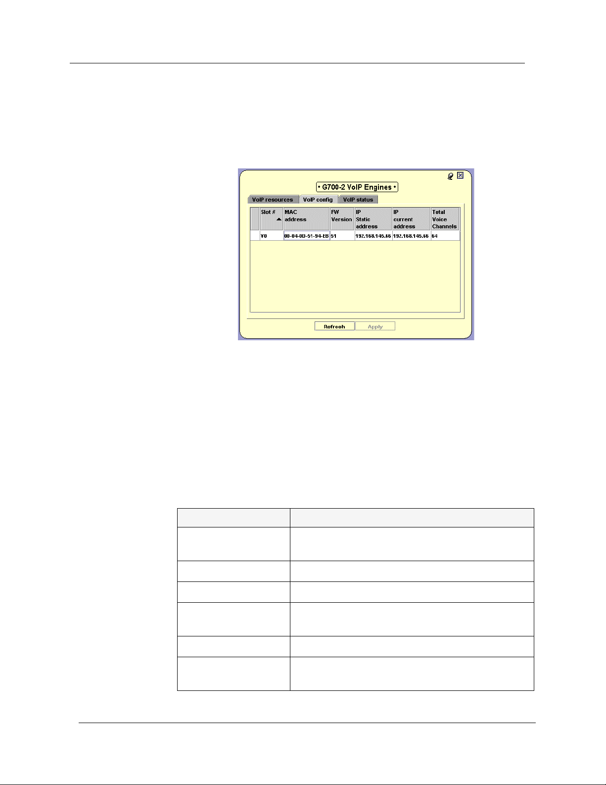
Chapter 6
VoIP Config
The VoIP config tab allows you to view information about a specific VoIP
engine’s configuration.
Figure 6-2. VoIP config Tab
You can configure the IP address to be used in the IP Static Address field.
In addition, it is possible to see how many VoIP channels are available on
this engine.
The information in the
VoIP config tab is provided by the VoIP engine and
is refreshed periodically.
The following table lists the fields in the VoIP config tab and their
description.
Table 6-5. VoIP config Parameters
Field Description
Slot #
The slot in which the VoIP media module
engine is located.
MAC address
FW Version
IP Static address
The MAC address of the VoIP engine.
The firmware version on the VoIP engine.
The IP address assigned to the VoIP Engine
when not using the DHCP server.
IP current address
The current IP address of the VoIP engine.
Total Voice Channels
T otal number of channels available for this VoIP
engine.
76 Avaya C360 Manager User Guide
Page 91

VoIP Status
VoIP Engine Configuration
The VoIP status tab provides information about a specific engine’s
operational status, jitter buffer size, and number of sessions open.
Figure 6-3. VoIP status Tab
The information in the
VoIP status tab is provided by the V oIP engine and is
refreshed periodically.
The following table lists the fields in the
descriptions.
Table 6-6. VoIP status Parameters
Field Description
Slot #
Channels in Use
Jitter Buffer Size
The slot in which the VoIP engine is located.
The number of channels currently being used.
The jitter buffer is a temporary storage area
built into the receiver of each gateway. It uses a
mechanism to remove the random delays
between packets, which occur as the packets are
routed through the network.
VoIP State
Operational Status
Fault Messages
The state of the VoIP engine.
The operational status of the VoIP engine.
Fault messages for the VoIP engine.
VoIP status tab and their
Avaya C360 Manager User Guide 77
Page 92

Chapter 6
78 Avaya C360 Manager User Guide
Page 93

7
WAN Configuration
This chapter provides information about configuring Avaya X330WAN
Expansion Modules and includes the following sections:
• X330WAN Overview
in Avaya C360 Devices.
• Avaya X330WAN Expansion Module Configuration
Information about viewing and configuring the X330WAN
Expansion Module.
• E1/T1 Port Configuration
configuring the E1/T1 ports on an X330WAN Expansion Module.
• Viewing Channel Group Information
viewing and configuring channel groups on E1/T1 ports.
• Managing Channel Groups
channel groups on E1/T1 ports.
• USP Configuration
configuring the Universal Serial ports (USPs) on an X330WAN
Expansion Module.
• Backup Interface Configuration
and configuring Backup interfaces.
For information on configuring the X330WAN’s Ethernet ports, refer to
Viewing Port Configuration” on page 39.
“
- An overview of X330WAN functionality
-
- Information about viewing and
- Information about
- Information about managing
- Information about viewing and
- Information about viewing
X330WAN Overview
The X330WAN is a WAN expansion module that can be inserted into
modules of the Avaya C360 line that include an expansion slot.
The X330WAN Expansion Module adds WAN connectivity to the
Avaya C360 stackable line. WAN connectivity provides a link to the
WAN enabling heavy data transfer over long distances. A WAN
connection can connect branch offices to headquarters. In addition,
WAN connectivity is essential for providing access to the Internet.
Avaya C360 Manager User Guide 79
Page 94

Chapter 7
Avaya X330WAN Expansion Module Configuration
The X330WAN Expansion Module configuration dialog box provides you
with information specific to a selected WAN expansion module. To view
the configuration of an expansion module:
Click the expansion module symbol in the Tree View.
Or
Click the expansion module’s label in the Chassis View. The
Expansion Module dialog box opens.
Figure 7-1. Expansion Module Dialog Box
The Expansion Module dialog box provides detailed information about
the module, such as the module’s name, IP address, location, description
and serial number.
For information about the fields in the Expansion Module dialog box,
refer to “
To apply changes to the X330WAN module configuration, click
T o save the changes to the X330WAN module configuration to the startup
configuration, click . The configuration changes are
saved.
80 Avaya C360 Manager User Guide
Viewing Module Configuration” on page 24.
Apply.
Page 95

E1/T1 Port Configuration
In addition to the Ethernet ports found on an Avaya C360 device, the
X330WAN expansion module may have E1/T1 ports. This section
provides information on viewing and configuring E1/T1 port parameters.
To display the E1/T1 Port Configuration dialog box, click the E1/T1 port’s
symbol in the Chassis View or the Tree View. The E1/T1 Port
Configuration dialog box opens.
Figure 7-2. E1/T1 Port Configuration Dialog Box
WAN Configuration
The E1/T1 port is used to connect to an E1 or T1 line. The E1/T1 Port
Configuration dialog box provides configuration and status information
about the E1/T1 port.
Avaya C360 Manager User Guide 81
Page 96

Chapter 7
The following table lists the E1/T1 Port Configuration fields and their
descriptions:
Table 7-1. E1/T1 Port Configuration Parameters
Field Description
Description
Port Type
The E1/T1 port description.
The type of E1/T1 port. Possible values are:
• E1 - For E1 and ISDN lines with 32
available channels.
• T1 - For T1 lines with 24 available
channels.
Port Functionality
Administrative Status
The type of E1 or T1 line.
The state of the selected port. Possible values
are:
• Enabled - The port is enabled and can
transmit and receive packets.
• Disabled - The port is disabled and cannot
transmit or receive packets.
Operational Status The operational status of the port.
Framing
The type of framing.
For an E1 line:
• CRC4
• no-CRC4
• Unframed
* Note: If Unframed is selected, all channels are
used for an unframed Channel Group,
and the Advanced tab does not appear in
the Channel Group dialog box.
For a T1 line:
• ESF
• SF
82 Avaya C360 Manager User Guide
Page 97

WAN Configuration
Table 7-1. E1/T1 Port Configuration Parameters (Continued)
Field Description
Linecode
The type of linecode. Possible values are:
For an E1 line:
• HDB3
• AMI
For a T1 line:
• B8ZS
• AMI
Cablelength (T1
The recommended maximum cable length.
only)
Gain (T1 only) The gain on this interface.
Clock Source The source of the Transmit Clock. Possible
sources include:
• Line - The recovered receive clock is used
as the transmit clock.
• Internal - The local clock is used as the
transmit clock.
FDL (T1 only) The type of FDL used on this interface. Possible
types include:
Local Loopback
Remote Loopback
(T1 only)
• ANSI
• AT&T
• Both - ANSI and AT&T FDl are both used
on this interface.
A request to use a local loopback. A local
loopback can be performed using:
• No Loopback
• Payload Loopback
• Line Loopback
• Diag Loopback
A request to use a remote loopback. A remote
loopback can be performed using:
• No Remote Loopback
• Remote Line
• Remote Payload
Avaya C360 Manager User Guide 83
Page 98

Chapter 7
Table 7-1. E1/T1 Port Configuration Parameters (Continued)
Field Description
Loopback status
Fault Messages Any faults that occurred on the port.
The type of loopback currently used by the port.
Possible values are:
• Near End Payload
• Near End Line
• Near End Inward
• Far End Payload
• Far End Line
Viewing Channel Group Information
The Channel Group dialog box contains provide information specific to a
selected Channel Group. The tabs that appear in the Channel Group
dialog box are dependant on the encapsulation method of the selected
Channel Group.
To view the Channel Group dialog box for a specific Channel Group:
1. Click a Channel Group symbol in the Chassis View. A list of
Channel Groups appears.
2. Click the Channel Group for which you want to view information.
The Channel Group dialog box for the selected Channel Group
opens.
* Note: Clicking
creation of a new Channel Group on the selected port. For
information about the Channel Group Wizard, refer to “
Channel Group Wizard” on page 101.
New opens the Channel Group wizard, enabling
Channel Group - PPP Session Information
The Channel Group dialog box for Channel Groups using PPP Sessions
contains three tabs:
• Channel Group
• Advanced
Channel Group.
• PPP
- Information about PPP on the Channel Group.
- Basic information about the Channel Group.
- Information about the channels that comprise the
The
84 Avaya C360 Manager User Guide
Page 99

WAN Configuration
Channel
Group
The Channel Group tab of the Channel Group dialog box provides basic
information about the selected Channel Group.
To view the Channel Group tab of the Channel Group dialog box:
1. Click a Channel Group icon in the Chassis View. A list of Channel
Groups on the port appears.
2. Click the Channel Group you want to configure. The Channel
Group dialog box opens with the Channel Group tab.
Figure 7-3. Channel Group Dialog Box - Channel Group Tab
The following table provides a list of the fields in the Channel Group tab
of the Channel Group dialog box and their descriptions:
Table 7-2. Channel Group Dialog Box -
Channel Group Parameters
Field Description
Description
Port Type
Port Functionality
A description of the PPP session.
The port type.
The framing mode of the port. Possible modes
are:
• ds0 bundle
• Unframed E1 (for E1 ports only)
Avaya C360 Manager User Guide 85
Page 100

Chapter 7
Table 7-2. Channel Group Dialog Box Channel Group Parameters (Continued)
Field Description
Encapsulation
The encapsulation method for the PPP session.
Possible encapsulation types are:
• PPP
• Frame Relay
Idle Characters The bit pattern used to signify an idle line.
Possible patterns include:
• Flags
• Mark
Bandwidth
Administrative Status
The effective bandwidth of the PPP session.
The administrative state of the PPP session:
• Enable - The PPP session is enabled.
• Disable - The PPP session is disabled.
VoIP Queue
The state of VoIP queuing on the PPP session.
VoIP queuing changes the length of the high
priority queue providing support for the
configuration of a maximum VoIP delay.
Possible states include:
• On - Voip queuing is active on the PPP
session. This enables the device’s queues
to optimally service VoIP applications.
• Off - Voip queuing is not active on the
PPP session.
86 Avaya C360 Manager User Guide
 Loading...