

Page 1

Installation and Configuration for the Avaya C360 Converged Stackable Switches
Software Version 4.5
10-601564
Issue 1
July 2006
Page 2

© 2006 Avaya Inc.
All Rights Reserved.
Notice
While reasonable efforts were made to ensu re that the i nformation in this
document was complete and accurate at the time of printing, Avaya In c.
can assume no liability for any errors. Changes and corrections to the
information in this document may be incorporated in future releases.
For full legal page information, please see the complete document,
Avaya Legal Page for Hardware Documentation, Document number
03-600759.
To locate this document on our web site, simply go to http://
www.avaya.com/support and search for the document number in
the search box.
Documentation disclaimer
Avaya Inc. is not responsible for any modificat ions, additions, or delet ions
to the original published version of this documentation unless such
modifications, additions, or deletions were performed by Avaya.
Customer and/or End User agree to indemnify and hold ha rmless A vaya,
Avaya's agents, servants and employ ees against all claims, lawsuits,
demands and judgments arising out of, or in connection with , subsequent
modifications, additions or deletions to this documentation to the extent
made by the Customer or End User.
Link disclaimer
Avaya Inc. is not responsible for the contents or reliability of any linked
Web sites referenced elsewhere within this documentation, and Avaya
does not necessarily endorse the products, services, or information
described or offered within them. We cannot guaran tee that these links
will work all of the time and we have no control over the availability of the
linked pages.
Warranty
Avaya Inc. provides a limited warranty on this product. Refer to your
sales agreement to establish the terms of the limited war ranty. In
addition, Avaya’s standard warranty language, as well as information
regarding support for this product, while under warranty, is available
through the following Web site:
http://www.avaya.com/support
Copyright
Except where expressly stated otherwise, the Product is protected by
copyright and other laws respecting proprietary rights. Unauthorized
reproduction, transfer , and or use can be a criminal, as well as a civil,
offense under the applicable law.
Avaya support
Avaya provides a telephone number for you to use to report problems or
to ask questions about your product. The support telephone number
is 1-800-242-2121 in the United S tates. For additional support telephone
numbers, see the Avaya Web site:
http://www.avaya.com/support
Page 3

Contents
Before you Install the Avaya C360 . . . . . . . . . . . . . . . . . . . . . 13
Safety Information . . . . . . . . . . . . . . . . . . . . . . . . . . . . . . . . . . . 13
Conventions Used in the Documentation . . . . . . . . . . . . . . . . . . . . . . 14
CLI Conventions . . . . . . . . . . . . . . . . . . . . . . . . . . . . . . . . . . 14
Notes, Cautions, and Warnings. . . . . . . . . . . . . . . . . . . . . . . . . . 15
Section 1: Avaya C360 Overview . . . . . . . . . . . . . . . . . . . 17
Chapter 1: Avaya C360 Overview. . . . . . . . . . . . . . . . . . . . . . 19
C360 Features and Benefits. . . . . . . . . . . . . . . . . . . . . . . . . . . . . . 19
Stacking . . . . . . . . . . . . . . . . . . . . . . . . . . . . . . . . . . . . . . 19
Network Optimization . . . . . . . . . . . . . . . . . . . . . . . . . . . . . . . 20
Manageability . . . . . . . . . . . . . . . . . . . . . . . . . . . . . . . . . . . 20
Redundancy . . . . . . . . . . . . . . . . . . . . . . . . . . . . . . . . . . . . 21
VLAN Support . . . . . . . . . . . . . . . . . . . . . . . . . . . . . . . . . . . 22
Security. . . . . . . . . . . . . . . . . . . . . . . . . . . . . . . . . . . . . . . 22
Quality of Service (QoS) . . . . . . . . . . . . . . . . . . . . . . . . . . . . . 23
Monitoring . . . . . . . . . . . . . . . . . . . . . . . . . . . . . . . . . . . . . 23
Power over Ethernet (PoE) Support on C360-PWR switches. . . . . . . . . . 24
Layer 3 Support . . . . . . . . . . . . . . . . . . . . . . . . . . . . . . . . . . 24
Management . . . . . . . . . . . . . . . . . . . . . . . . . . . . . . . . . . . . 25
Management Interface Options . . . . . . . . . . . . . . . . . . . . . . . . 25
C360 Switch Configurations . . . . . . . . . . . . . . . . . . . . . . . . . . . . . 26
Section 2: Installing the C360 . . . . . . . . . . . . . . . . . . . . . 27
Chapter 2: Avaya C360 Front and Rear Panels . . . . . . . . . . . . . . 29
C360 Front Panels . . . . . . . . . . . . . . . . . . . . . . . . . . . . . . . . . . . 29
C360 Rear Panel . . . . . . . . . . . . . . . . . . . . . . . . . . . . . . . . . . . . 33
Chapter 3: Installation. . . . . . . . . . . . . . . . . . . . . . . . . . . . 35
Preparing Needed Tools. . . . . . . . . . . . . . . . . . . . . . . . . . . . . . . . 35
Site Preparation . . . . . . . . . . . . . . . . . . . . . . . . . . . . . . . . . . . . 36
Rack Mounting (Optional). . . . . . . . . . . . . . . . . . . . . . . . . . . . . . . 37
Before you Install the C360 in a Rack . . . . . . . . . . . . . . . . . . . . 38
Wall Mounting (Optional) . . . . . . . . . . . . . . . . . . . . . . . . . . . . . . . 40
Stacking (optional). . . . . . . . . . . . . . . . . . . . . . . . . . . . . . . . . . . 41
Installing the X360STK Stacking Module. . . . . . . . . . . . . . . . . . . . . 41
Issue 1 July 2006 3
Page 4

Contents
Inter-Connecting Switches . . . . . . . . . . . . . . . . . . . . . . . . . . . . 42
To connect stacked switches: . . . . . . . . . . . . . . . . . . . . . . . . 42
Making Connections to Network Equipment. . . . . . . . . . . . . . . . . . . . . 44
Prerequisites . . . . . . . . . . . . . . . . . . . . . . . . . . . . . . . . . . . . 44
Connecting Cables to Network Equipment . . . . . . . . . . . . . . . . . . . 44
Installing SFP GBIC Transceivers . . . . . . . . . . . . . . . . . . . . . . . . . . 45
Safety Information . . . . . . . . . . . . . . . . . . . . . . . . . . . . . . . . . 45
Usage Restriction . . . . . . . . . . . . . . . . . . . . . . . . . . . . . . . 45
Installing and Removing a SFP GBIC Transceiver . . . . . . . . . . . . . . . 46
Copper GBIC Transceiver Installation Notes . . . . . . . . . . . . . . . . 47
Chapter 4: Powering Up the Avaya C360 . . . . . . . . . . . . . . . . . 49
Connecting to an AC Power Supply . . . . . . . . . . . . . . . . . . . . . . . . . 50
AC Power Cable . . . . . . . . . . . . . . . . . . . . . . . . . . . . . . . . . . 50
Connecting to a DC Power Source (C364T NEBS Only) . . . . . . . . . . . . . . 51
Connecting a BUPS . . . . . . . . . . . . . . . . . . . . . . . . . . . . . . . . . . 53
Supplemental Earthing of the C360 (Optional) . . . . . . . . . . . . . . . . . 54
Sample Backup Power Supply Scheme . . . . . . . . . . . . . . . . . . . . . 55
Budgeting Power . . . . . . . . . . . . . . . . . . . . . . . . . . . . . . . . . 57
Post-Installation . . . . . . . . . . . . . . . . . . . . . . . . . . . . . . . . . . . . 58
Chapter 5: Establishing Switch Access . . . . . . . . . . . . . . . . . . 59
CLI Architecture . . . . . . . . . . . . . . . . . . . . . . . . . . . . . . . . . . . . 60
Security Levels. . . . . . . . . . . . . . . . . . . . . . . . . . . . . . . . . . . . . 60
Entering the Supervisor Level . . . . . . . . . . . . . . . . . . . . . . . . . . 61
Defining new local users . . . . . . . . . . . . . . . . . . . . . . . . . . . 61
Exiting the Supervisor Level . . . . . . . . . . . . . . . . . . . . . . . . . 61
Entering the CLI . . . . . . . . . . . . . . . . . . . . . . . . . . . . . . . . . . . . 62
Establishing a Console Connection . . . . . . . . . . . . . . . . . . . . . . . . . 62
Assigning C360 IP Stack Address . . . . . . . . . . . . . . . . . . . . . . . . . . 64
Establishing a Telnet Connection. . . . . . . . . . . . . . . . . . . . . . . . . . . 65
Establishing an SSH Connection. . . . . . . . . . . . . . . . . . . . . . . . . . . 66
Introduction to SSH . . . . . . . . . . . . . . . . . . . . . . . . . . . . . . . . 66
SSH client connection: . . . . . . . . . . . . . . . . . . . . . . . . . . . . . . 66
User Authentication . . . . . . . . . . . . . . . . . . . . . . . . . . . . . . . . 67
Procedure for Establishing an SSH Connection. . . . . . . . . . . . . . . . . 68
SSH Commands . . . . . . . . . . . . . . . . . . . . . . . . . . . . . . . . . . 69
Establishing Access to Other Entities in the Stack (C360 Sessions) . . . . . . . 70
Establishing a Modem (PPP) Connection . . . . . . . . . . . . . . . . . . . . . . 71
4 Installation and Configuration Guide Avaya C360 Multilayer Stackable Switches, version 4.5
Page 5

Connecting a Modem to the Console Port . . . . . . . . . . . . . . . . . . . . 71
SNMP Support . . . . . . . . . . . . . . . . . . . . . . . . . . . . . . . . . . . . . 73
Introduction to SNMP . . . . . . . . . . . . . . . . . . . . . . . . . . . . . . . 73
SNMP Versions. . . . . . . . . . . . . . . . . . . . . . . . . . . . . . . . . 73
Managers and Agents . . . . . . . . . . . . . . . . . . . . . . . . . . . . . 73
Manager/Agent Communication . . . . . . . . . . . . . . . . . . . . . . . 73
SNMPv1. . . . . . . . . . . . . . . . . . . . . . . . . . . . . . . . . . . . . . . 74
SNMPv2c . . . . . . . . . . . . . . . . . . . . . . . . . . . . . . . . . . . . . . 74
SNMPv3. . . . . . . . . . . . . . . . . . . . . . . . . . . . . . . . . . . . . . . 75
Users . . . . . . . . . . . . . . . . . . . . . . . . . . . . . . . . . . . . . . 75
Groups . . . . . . . . . . . . . . . . . . . . . . . . . . . . . . . . . . . . . 76
Views . . . . . . . . . . . . . . . . . . . . . . . . . . . . . . . . . . . . . . 77
SNMP Commands . . . . . . . . . . . . . . . . . . . . . . . . . . . . . . . . . 77
RADIUS. . . . . . . . . . . . . . . . . . . . . . . . . . . . . . . . . . . . . . . . . 80
Introduction to RADIUS . . . . . . . . . . . . . . . . . . . . . . . . . . . . . . 80
RADIUS Commands . . . . . . . . . . . . . . . . . . . . . . . . . . . . . . . . 82
Recovery Password . . . . . . . . . . . . . . . . . . . . . . . . . . . . . . . . . . 83
Introduction to Recovery Password . . . . . . . . . . . . . . . . . . . . . . . 83
Recovery Password CLI Commands . . . . . . . . . . . . . . . . . . . . . . . 83
Contents
Allowed Managers . . . . . . . . . . . . . . . . . . . . . . . . . . . . . . . . . . . 84
Allowed Managers Introduction . . . . . . . . . . . . . . . . . . . . . . . . . 84
Allowed Managers CLI Commands. . . . . . . . . . . . . . . . . . . . . . . . 84
Allowed Protocols . . . . . . . . . . . . . . . . . . . . . . . . . . . . . . . . . . . 86
Allowed Protocols Introduction. . . . . . . . . . . . . . . . . . . . . . . . . . 86
Allowed Protocols CLI Commands . . . . . . . . . . . . . . . . . . . . . . . . 86
Section 3: Avaya C360 Configuration. . . . . . . . . . . . . . . . . 89
Chapter 6: Avaya C360 Default Settings . . . . . . . . . . . . . . . . . . 91
Configuring the Switch . . . . . . . . . . . . . . . . . . . . . . . . . . . . . . . . 91
C360 Default Settings . . . . . . . . . . . . . . . . . . . . . . . . . . . . . . . 91
Chapter 7: Switch Configuration . . . . . . . . . . . . . . . . . . . . . . 95
Introduction . . . . . . . . . . . . . . . . . . . . . . . . . . . . . . . . . . . . . . 95
Basic Switch Configuration. . . . . . . . . . . . . . . . . . . . . . . . . . . . . . 95
System Parameter Configuration. . . . . . . . . . . . . . . . . . . . . . . . . 96
Identifying the system. . . . . . . . . . . . . . . . . . . . . . . . . . . . . 96
Operating parameters . . . . . . . . . . . . . . . . . . . . . . . . . . . . . 97
Network Time Acquiring Protocols Parameter Configuration . . . . . . . . . 97
Issue 1 July 2006 5
Page 6

Contents
Uploading and Downloading Device Configurations and Images . . . . . . . . . 99
Layer 2 Configuration File. . . . . . . . . . . . . . . . . . . . . . . . . . . . . 100
Layer 3 Configuration File. . . . . . . . . . . . . . . . . . . . . . . . . . . . . 101
SCP Protocol Support. . . . . . . . . . . . . . . . . . . . . . . . . . . . . . . . . 103
System Logging . . . . . . . . . . . . . . . . . . . . . . . . . . . . . . . . . . . . 104
System Logging Introduction. . . . . . . . . . . . . . . . . . . . . . . . . . . 104
System Logging Messages . . . . . . . . . . . . . . . . . . . . . . . . . . 104
Sinks . . . . . . . . . . . . . . . . . . . . . . . . . . . . . . . . . . . . . . 105
Message Facilities . . . . . . . . . . . . . . . . . . . . . . . . . . . . . . . 105
Syslog Servers. . . . . . . . . . . . . . . . . . . . . . . . . . . . . . . . . . . 106
Telnet Client Support . . . . . . . . . . . . . . . . . . . . . . . . . . . . . . . . . 109
Introduction to Telnet . . . . . . . . . . . . . . . . . . . . . . . . . . . . . . . 109
Telnet Commands . . . . . . . . . . . . . . . . . . . . . . . . . . . . . . . . . 109
Monitoring CPU Utilization . . . . . . . . . . . . . . . . . . . . . . . . . . . . . . 110
Chapter 8: Avaya C360 Layer 2 Features . . . . . . . . . . . . . . . . . 111
Ethernet . . . . . . . . . . . . . . . . . . . . . . . . . . . . . . . . . . . . . . . . 111
Fast Ethernet. . . . . . . . . . . . . . . . . . . . . . . . . . . . . . . . . . . . 112
Gigabit Ethernet . . . . . . . . . . . . . . . . . . . . . . . . . . . . . . . . . . 112
Configuring Ethernet Parameters . . . . . . . . . . . . . . . . . . . . . . . . 113
Auto-Negotiation. . . . . . . . . . . . . . . . . . . . . . . . . . . . . . . . 113
Full-Duplex/Half-Duplex . . . . . . . . . . . . . . . . . . . . . . . . . . . . 113
Speed . . . . . . . . . . . . . . . . . . . . . . . . . . . . . . . . . . . . . . 113
MDI/MDI-X Detection. . . . . . . . . . . . . . . . . . . . . . . . . . . . . . 113
Flow Control . . . . . . . . . . . . . . . . . . . . . . . . . . . . . . . . . . 113
Priority . . . . . . . . . . . . . . . . . . . . . . . . . . . . . . . . . . . . . 114
MAC Address. . . . . . . . . . . . . . . . . . . . . . . . . . . . . . . . . . 114
CAM Table . . . . . . . . . . . . . . . . . . . . . . . . . . . . . . . . . . . 115
MAC Aging . . . . . . . . . . . . . . . . . . . . . . . . . . . . . . . . . . . 115
Ethernet Configuration CLI Commands . . . . . . . . . . . . . . . . . . . . . 115
VLANs . . . . . . . . . . . . . . . . . . . . . . . . . . . . . . . . . . . . . . . . . 117
VLAN Overview . . . . . . . . . . . . . . . . . . . . . . . . . . . . . . . . . . 117
VLAN Tagging . . . . . . . . . . . . . . . . . . . . . . . . . . . . . . . . . . . 119
Multi VLAN Binding . . . . . . . . . . . . . . . . . . . . . . . . . . . . . . . . 119
Ingress VLAN Security . . . . . . . . . . . . . . . . . . . . . . . . . . . . . . 121
VLAN CLI Commands . . . . . . . . . . . . . . . . . . . . . . . . . . . . . . . 122
IEEE 802.1x (Port Based Network Access Control) . . . . . . . . . . . . . . . . . 123
How 802.1x Authentication Works . . . . . . . . . . . . . . . . . . . . . . . . 123
IEEE 802.1x Implementation in the C360. . . . . . . . . . . . . . . . . . . . . 124
Configuring the C360 for 802.1x . . . . . . . . . . . . . . . . . . . . . . . . . 124
6 Installation and Configuration Guide Avaya C360 Multilayer Stackable Switches, version 4.5
Page 7

802.1x CLI Commands. . . . . . . . . . . . . . . . . . . . . . . . . . . . . . . 125
Spanning Tree Protocol . . . . . . . . . . . . . . . . . . . . . . . . . . . . . . . . 127
Overview . . . . . . . . . . . . . . . . . . . . . . . . . . . . . . . . . . . . . . 127
Spanning Tree Protocol . . . . . . . . . . . . . . . . . . . . . . . . . . . . . . 127
Spanning Tree per Port . . . . . . . . . . . . . . . . . . . . . . . . . . . . . . 128
Rapid Spanning Tree Protocol (RSTP) . . . . . . . . . . . . . . . . . . . . . . 128
About the 802.1w Standard . . . . . . . . . . . . . . . . . . . . . . . . . . 128
Port Roles . . . . . . . . . . . . . . . . . . . . . . . . . . . . . . . . . . . 129
Spanning Tree Implementation in the C360 . . . . . . . . . . . . . . . . . . . 130
Spanning Tree Protocol CLI Commands. . . . . . . . . . . . . . . . . . . . . 131
MAC Security. . . . . . . . . . . . . . . . . . . . . . . . . . . . . . . . . . . . . . 132
MAC Security Implementation in the C360. . . . . . . . . . . . . . . . . . . . 132
MAC Security CLI Commands . . . . . . . . . . . . . . . . . . . . . . . . . . 133
LAG (Link Aggregate Group) . . . . . . . . . . . . . . . . . . . . . . . . . . . . . 134
LAG Overview . . . . . . . . . . . . . . . . . . . . . . . . . . . . . . . . . . . 134
LAG CLI Commands. . . . . . . . . . . . . . . . . . . . . . . . . . . . . . . . 134
LAG Implementation in the C360 . . . . . . . . . . . . . . . . . . . . . . . . . 135
Contents
Port Redundancy . . . . . . . . . . . . . . . . . . . . . . . . . . . . . . . . . . . 135
Port Redundancy Operation . . . . . . . . . . . . . . . . . . . . . . . . . . . 136
Intermodule Port Redundancy . . . . . . . . . . . . . . . . . . . . . . . . . . 137
Port Redundancy CLI Commands . . . . . . . . . . . . . . . . . . . . . . . . 138
Port Classification . . . . . . . . . . . . . . . . . . . . . . . . . . . . . . . . . 139
Overview . . . . . . . . . . . . . . . . . . . . . . . . . . . . . . . . . . . . 139
Port Classification CLI Commands. . . . . . . . . . . . . . . . . . . . . . 139
IP Multicast Filtering . . . . . . . . . . . . . . . . . . . . . . . . . . . . . . . . . . 139
Overview . . . . . . . . . . . . . . . . . . . . . . . . . . . . . . . . . . . . . . 139
IP Multicast CLI Commands. . . . . . . . . . . . . . . . . . . . . . . . . . . . 141
RMON. . . . . . . . . . . . . . . . . . . . . . . . . . . . . . . . . . . . . . . . . . 141
RMON Overview . . . . . . . . . . . . . . . . . . . . . . . . . . . . . . . . . . 141
RMON CLI Commands. . . . . . . . . . . . . . . . . . . . . . . . . . . . . . . 142
SMON. . . . . . . . . . . . . . . . . . . . . . . . . . . . . . . . . . . . . . . . . . 143
SMON Overview . . . . . . . . . . . . . . . . . . . . . . . . . . . . . . . . . . 143
SMON CLI Commands. . . . . . . . . . . . . . . . . . . . . . . . . . . . . 144
Port Mirroring . . . . . . . . . . . . . . . . . . . . . . . . . . . . . . . . . . . . . 144
Port Mirroring Overview. . . . . . . . . . . . . . . . . . . . . . . . . . . . . . 144
Port Mirroring CLI commands . . . . . . . . . . . . . . . . . . . . . . . . . . 145
Port Mirroring Implementation in the C360 . . . . . . . . . . . . . . . . . . . 145
Weighted Queuing. . . . . . . . . . . . . . . . . . . . . . . . . . . . . . . . . . . 145
Implementation of Weighted Queuing in the C360 . . . . . . . . . . . . . . . 145
Issue 1 July 2006 7
Page 8

Contents
Weighted Queuing CLI Commands. . . . . . . . . . . . . . . . . . . . . . . . 146
LLDP Agent . . . . . . . . . . . . . . . . . . . . . . . . . . . . . . . . . . . . . . 146
LLDP Agent Overview . . . . . . . . . . . . . . . . . . . . . . . . . . . . . . . 146
Supported TLVs . . . . . . . . . . . . . . . . . . . . . . . . . . . . . . . . 147
Configuring the LLDP Agent . . . . . . . . . . . . . . . . . . . . . . . . . . . 148
LLDP Agent CLI Commands . . . . . . . . . . . . . . . . . . . . . . . . . . . 149
Chapter 9: Avaya C360 Layer 3 Features . . . . . . . . . . . . . . . . . 151
Obtaining and Activating a License Key . . . . . . . . . . . . . . . . . . . . . . . 151
Obtaining a Routing License Key. . . . . . . . . . . . . . . . . . . . . . . . . 152
Activating a Routing License Key . . . . . . . . . . . . . . . . . . . . . . . . 158
License Key CLI Commands . . . . . . . . . . . . . . . . . . . . . . . . . 158
What is Routing? . . . . . . . . . . . . . . . . . . . . . . . . . . . . . . . . . . . 158
Routing Configuration . . . . . . . . . . . . . . . . . . . . . . . . . . . . . . . . . 161
Forwarding . . . . . . . . . . . . . . . . . . . . . . . . . . . . . . . . . . . . . 161
Multinetting (Multiple Subnets per VLAN) . . . . . . . . . . . . . . . . . . . . 161
IP Configuration . . . . . . . . . . . . . . . . . . . . . . . . . . . . . . . . . . . . 162
IP Configuration CLI Commands . . . . . . . . . . . . . . . . . . . . . . . . . 162
Assigning Initial Router Parameters. . . . . . . . . . . . . . . . . . . . . . . 163
RIP (Routing Interchange Protocol) Configuration . . . . . . . . . . . . . . . . . 164
RIP Overview. . . . . . . . . . . . . . . . . . . . . . . . . . . . . . . . . . . . 164
RIP2. . . . . . . . . . . . . . . . . . . . . . . . . . . . . . . . . . . . . . . . . 165
RIP CLI Commands . . . . . . . . . . . . . . . . . . . . . . . . . . . . . . . . 166
OSPF (Open Shortest Path First) Configuration. . . . . . . . . . . . . . . . . . . 167
OSPF Overview . . . . . . . . . . . . . . . . . . . . . . . . . . . . . . . . . . 167
OSPF CLI Commands . . . . . . . . . . . . . . . . . . . . . . . . . . . . . . . 168
Static Routing Configuration . . . . . . . . . . . . . . . . . . . . . . . . . . . . . 169
Static Routing Overview. . . . . . . . . . . . . . . . . . . . . . . . . . . . . . 169
Static Routing Configuration CLI Commands . . . . . . . . . . . . . . . . . . 170
Route Preferences. . . . . . . . . . . . . . . . . . . . . . . . . . . . . . . . . 170
Route Redistribution . . . . . . . . . . . . . . . . . . . . . . . . . . . . . . . . . 171
Route Redistribution Commands. . . . . . . . . . . . . . . . . . . . . . . . . 172
ARP (Address Resolution Protocol) Table Configuration. . . . . . . . . . . . . . 172
ARP Overview . . . . . . . . . . . . . . . . . . . . . . . . . . . . . . . . . . . 172
The ARP Table . . . . . . . . . . . . . . . . . . . . . . . . . . . . . . . . . 173
ARP CLI Commands. . . . . . . . . . . . . . . . . . . . . . . . . . . . . . . . 174
BOOTP/DHCP (Dynamic Host Configuration Protocol) Relay Configuration . . . 175
BOOTP/DHCP Overview. . . . . . . . . . . . . . . . . . . . . . . . . . . . . . 175
BOOTP . . . . . . . . . . . . . . . . . . . . . . . . . . . . . . . . . . . . . 175
8 Installation and Configuration Guide Avaya C360 Multilayer Stackable Switches, version 4.5
Page 9

DHCP . . . . . . . . . . . . . . . . . . . . . . . . . . . . . . . . . . . . . . 175
DHCP/BOOTP Relay . . . . . . . . . . . . . . . . . . . . . . . . . . . . . . 175
BOOTP/DHCP CLI Commands . . . . . . . . . . . . . . . . . . . . . . . . . . 176
NetBIOS Re-broadcast Configuration . . . . . . . . . . . . . . . . . . . . . . . . 176
NetBIOS Overview . . . . . . . . . . . . . . . . . . . . . . . . . . . . . . . . . 176
NetBIOS Re-broadcast Configuration CLI Commands . . . . . . . . . . . . . 177
VRRP (Virtual Router Redundancy Protocol) Configuration . . . . . . . . . . . . 177
VRRP Overview . . . . . . . . . . . . . . . . . . . . . . . . . . . . . . . . . . 177
VRRP Configuration Example 1. . . . . . . . . . . . . . . . . . . . . . . . . . 178
Case#1 . . . . . . . . . . . . . . . . . . . . . . . . . . . . . . . . . . . . . 178
Case #2 . . . . . . . . . . . . . . . . . . . . . . . . . . . . . . . . . . . . . 179
VRRP CLI Commands . . . . . . . . . . . . . . . . . . . . . . . . . . . . . . . 179
Policy Configuration . . . . . . . . . . . . . . . . . . . . . . . . . . . . . . . . . . 180
Policy Configuration Overview . . . . . . . . . . . . . . . . . . . . . . . . . . 180
Policy Configuration CLI Commands . . . . . . . . . . . . . . . . . . . . . . 181
Policy Configuration Example . . . . . . . . . . . . . . . . . . . . . . . . . . 183
Policy Configuration Example . . . . . . . . . . . . . . . . . . . . . . . . . . 184
Contents
IP Fragmentation and Reassembly. . . . . . . . . . . . . . . . . . . . . . . . . . 184
IP Fragmentation and Reassembly Overview . . . . . . . . . . . . . . . . . . 184
IP Fragmentation/Reassembly CLI Commands . . . . . . . . . . . . . . . . . 185
Chapter 10: Avaya C360 Power over Ethernet Features . . . . . . . . . 187
Power Over Ethernet . . . . . . . . . . . . . . . . . . . . . . . . . . . . . . . . . 187
Load Detection. . . . . . . . . . . . . . . . . . . . . . . . . . . . . . . . . . . 187
How the C360-PWR Switches Detect a Powered Device . . . . . . . . . . 188
Specific Resistance Signature (IEEE 802.3af) . . . . . . . . . . . . . . . . 188
PD Connected . . . . . . . . . . . . . . . . . . . . . . . . . . . . . . . . . 188
“Plug and Play" Operation . . . . . . . . . . . . . . . . . . . . . . . . . . . . 189
Powering Devices . . . . . . . . . . . . . . . . . . . . . . . . . . . . . . . . . 189
Priority . . . . . . . . . . . . . . . . . . . . . . . . . . . . . . . . . . . . . 189
Power over Ethernet in Converged Networks . . . . . . . . . . . . . . . . . . 190
Power over Ethernet CLI Commands. . . . . . . . . . . . . . . . . . . . . . . 191
Chapter 11: C360 Device Manager . . . . . . . . . . . . . . . . . . . . . 193
Overview . . . . . . . . . . . . . . . . . . . . . . . . . . . . . . . . . . . . . . . . 193
System Requirements. . . . . . . . . . . . . . . . . . . . . . . . . . . . . . . . . 194
Configuring the Device Manager . . . . . . . . . . . . . . . . . . . . . . . . . . . 194
Device Manager Commands . . . . . . . . . . . . . . . . . . . . . . . . . . . 194
Running the Device Manager . . . . . . . . . . . . . . . . . . . . . . . . . . . . . 195
Issue 1 July 2006 9
Page 10

Contents
Installing the Java Plug-in. . . . . . . . . . . . . . . . . . . . . . . . . . . . . . . 197
Installing from the C360 Documentation and Utilities CD . . . . . . . . . . . 197
Install from the Avaya Web Site . . . . . . . . . . . . . . . . . . . . . . . . . 197
Install from your Local Web Site . . . . . . . . . . . . . . . . . . . . . . . . . 197
Installing the On-Line Help and Java Plug-In on your Web Site . . . . . . . . . . 198
Documentation. . . . . . . . . . . . . . . . . . . . . . . . . . . . . . . . . . . . . 198
Section 4: Troubleshooting and Maintaining the Avaya C360 . . . 199
Chapter 12: Troubleshooting the Installation . . . . . . . . . . . . . . . 201
Troubleshooting the Installation . . . . . . . . . . . . . . . . . . . . . . . . . . . 201
Stack Health . . . . . . . . . . . . . . . . . . . . . . . . . . . . . . . . . . . . . . 204
Overview . . . . . . . . . . . . . . . . . . . . . . . . . . . . . . . . . . . . . . 204
Implementation of Stack Health in the C360. . . . . . . . . . . . . . . . . . . 204
Stack Health CLI Commands . . . . . . . . . . . . . . . . . . . . . . . . . . . 205
Chapter 13: Maintenance . . . . . . . . . . . . . . . . . . . . . . . . . . 207
Introduction . . . . . . . . . . . . . . . . . . . . . . . . . . . . . . . . . . . . . . 207
Replacing the Stacking Module. . . . . . . . . . . . . . . . . . . . . . . . . . . . 207
Hardware NVRAM Initialization . . . . . . . . . . . . . . . . . . . . . . . . . . . . 208
Chapter 14: Updating the Firmware . . . . . . . . . . . . . . . . . . . . 211
Firmware Download . . . . . . . . . . . . . . . . . . . . . . . . . . . . . . . . . . 211
Obtain Software Online . . . . . . . . . . . . . . . . . . . . . . . . . . . . . . 211
Downloading Firmware . . . . . . . . . . . . . . . . . . . . . . . . . . . . . . 211
Download New Version without Overwriting Existing Version . . . . . . . . . . . 212
Firmware Banks . . . . . . . . . . . . . . . . . . . . . . . . . . . . . . . . . . 212
Appendix A: Mixed Stacks . . . . . . . . . . . . . . . . . . . . . . . . . 213
Hardware Compatibility . . . . . . . . . . . . . . . . . . . . . . . . . . . . . . . . 214
Stacking . . . . . . . . . . . . . . . . . . . . . . . . . . . . . . . . . . . . . . 214
BUPS . . . . . . . . . . . . . . . . . . . . . . . . . . . . . . . . . . . . . . . . 215
Feature Compatibility . . . . . . . . . . . . . . . . . . . . . . . . . . . . . . . . . 216
QoS Mapping. . . . . . . . . . . . . . . . . . . . . . . . . . . . . . . . . . . . 217
Appendix B: Configuring C360 QoS for Avaya IP Telephones . . . . . . 219
Introduction . . . . . . . . . . . . . . . . . . . . . . . . . . . . . . . . . . . . . . 219
10 Installation and Configuration Guide Avaya C360 Multilayer Stackable Switches, version 4.5
Page 11

Appendix C: Standards and Compatibility. . . . . . . . . . . . . . . . . 221
Avaya C360 Standards Supported . . . . . . . . . . . . . . . . . . . . . . . . . . 221
IEEE. . . . . . . . . . . . . . . . . . . . . . . . . . . . . . . . . . . . . . . . . 221
IETF - Layer 2 . . . . . . . . . . . . . . . . . . . . . . . . . . . . . . . . . . . 221
IETF - Layer 3 . . . . . . . . . . . . . . . . . . . . . . . . . . . . . . . . . . . 222
IETF - Network Monitoring . . . . . . . . . . . . . . . . . . . . . . . . . . . . . . 223
Appendix D: Specifications. . . . . . . . . . . . . . . . . . . . . . . . . 225
Physical . . . . . . . . . . . . . . . . . . . . . . . . . . . . . . . . . . . . . . . . 225
Power Requirements . . . . . . . . . . . . . . . . . . . . . . . . . . . . . . . . . 226
Environmental.. . . . . . . . . . . . . . . . . . . . . . . . . . . . . . . . . . . . . 227
Safety. . . . . . . . . . . . . . . . . . . . . . . . . . . . . . . . . . . . . . . . . . 227
MTBF . . . . . . . . . . . . . . . . . . . . . . . . . . . . . . . . . . . . . . . . . . 228
Interfaces. . . . . . . . . . . . . . . . . . . . . . . . . . . . . . . . . . . . . . . . 228
GBIC Transceivers. . . . . . . . . . . . . . . . . . . . . . . . . . . . . . . . . . . 228
LX Transceiver. . . . . . . . . . . . . . . . . . . . . . . . . . . . . . . . . . . 228
SX Transceiver. . . . . . . . . . . . . . . . . . . . . . . . . . . . . . . . . . . 229
ELX Transceiver . . . . . . . . . . . . . . . . . . . . . . . . . . . . . . . . . . 229
Copper Transceiver . . . . . . . . . . . . . . . . . . . . . . . . . . . . . . . . 229
Console Pin Assignments. . . . . . . . . . . . . . . . . . . . . . . . . . . . . . . 230
Ethernet . . . . . . . . . . . . . . . . . . . . . . . . . . . . . . . . . . . . . . . . 231
Contents
Index . . . . . . . . . . . . . . . . . . . . . . . . . . . . . . . . . . 233
Issue 1 July 2006 11
Page 12

Contents
12 Installation and Configuration Guide Avaya C360 Multilayer Stackable Switches, version 4.5
Page 13
Before you Install the Avaya C360
Safety Information
!
WARNING:
WARNING: ONLY TRAINED AND QUALIFIED PERSONNEL SHOULD BE ALLOWED TO
INSTALL OR REPLACE THIS EQUIPMENT.
!
ADVERTENCIA:
ADVERTENCIA: SOLAMENTE PERSONAL CALIFICADO Y ENTRENADO DEBE INSTALAR O
REEMPLAZAR ESTE EQUIPO.
!
WARNING:
WARNING: EQUIPMENT MUST BE CONNECTED TO AN EARTHED MAINS
SOCKET-OUTLET.
!
ADVERTENCIA:
ADVERTENCIA: El equipo se debe conectar a una toma de tierra principal.
!
CAUTION:
CAUTION: C360 switches and stacking modules contain components sensitive to
electrostatic discharge. Touching the circuit boards unless instructed to do so
may damage them.
!
PRECAUCIÓN:
PRECAUCION: El switch C360 y sus módulos de ampliación contienen componentes sensibles a
descargas electrostáticas. Tocar las tarjetas sin autorización del persona l técnico
puede dañarlas.
!
CAUTION:
CAUTION: Do not leave the stacking slots open. Cover empty slots using the blanking plates
supplied.
!
PRECAUCIÓN:
PRECAUCION: No deje las aberturas de ampliación abiertas. Cubrir las aberturas vacias con las
placas bloqueadoras proporcionadas con el equipo.
!
WARNING:
WARNING: The fans are on whenever the switch is powered.
Issue 1 July 2006 13
Page 14

Before you Install the Avaya C360
!
ADVERTENCIA:
ADVERTENCIA: Los ventiladores están encendidos siempre que el equipo esté conectado
al suministro eléctrico.
Conventions Used in the Documentation
Documentation for this product uses the following conventions to convey instructions and
information:
CLI Conventions
● Mandatory keywords are in the computer bold font.
● Information displayed on screen is displayed in computer font.
● Variables that you supply are in pointed brackets < >.
● Optional keywords are in square brackets [ ].
● Alternative but mandatory keywords are grouped in braces {} and separated by a vertical
bar |.
● Lists of parameters from which you should choose are enclosed in square brackets [ ] and
separated by a vertical bar |.
● If you enter an alphanumeric string of two words or more, enclose the string in “quotation
marks”.
14 Installation and Configuration Guide Avaya C360 Multilayer Stackable Switches, version 4.5
Page 15
Notes, Cautions, and Warnings
!
CAUTION:
CAUTION: You should take care. You could do something that may damage equipment or
result in loss of data.
!
PRECAUCIÓN:
PRECAUCION: Debe tener cuidado. Usted podría hacer algo que puede dañar el equipo o
resultar en pérdida de datos.
!
WARNING:
WARNING: This means danger. Failure to follow the instructions or warnings may result in
bodily injury. You sh ould ensure tha t you are qualifie d for this task and have read
and understood all the instructions.
!
ADVERTENCIA:
ADVERTENCIA: Indica peligro. El no seguir las instrucciones o advertencias p uede resultar
en lesión corporal. Asegúrese de estar prep arado para est a ta rea y de haber
leído y entendido todas las instrucciones.
Conventions Used in the Documentation
Issue 1 July 2006 15
Page 16

Before you Install the Avaya C360
16 Installation and Configuration Guide Avaya C360 Multilayer Stackable Switches, version 4.5
Page 17

Section 1: Avaya C360 Overview
Issue 1 July 2006 17
Page 18

18 Installation and Configuration Guide Avaya C360 Multilayer Stackable Switches, version 4.5
Page 19
Chapter 1: Avaya C360 Overview
The C360 is a line of converged stackable switches that provide high availability, quality of
service (QoS), and IEEE 802.3af Power over Ethernet (PoE) to enhance converged network
infrastructure operations. With a range of PoE and non-PoE configurations, the C360 series is a
powerful, yet cost-effective option for enterprise applications.
With C360 switches, you can deploy PoE and multilayer switching using one switch, while
maintaining the simplicity and the cost effectiveness of Avaya stackable switches.
Tip:
Tip: For clarity, the nomenclature described in Table 1 will be used in the C360
documentation:
Table 1: Nomenclature
This term... Means...
C360
C360-PWR
C360 Features and Benefits
Stacking
● You may create logical stacks of up to ten switches that you manage and configure as a
single switch.
● C363T
● C363T-PWR
● C364T
● C364T NEBS
● C364T-PWR
● C363T-PWR
● C364T-PWR
● Stacking is based on the Octaplane™ stacking system that provides eight Gbps stacking
bandwidth to all switches in the stack.
● Each member of the stack is connected to the other members using a dedicated stacking
module and cables.
Issue 1 July 2006 19
Page 20

Avaya C360 Overview
● When the switches are stacked, the switches elect one switch as the master, while the
other switches act as slaves. The master switch acts as the stack management agent
reporting to the management system.
● Management redundancy - if the master unit fails, the remaining switches elect a new
switch as the master, and the original stack configuration and IP address are maintained.
● You can add, remove and replace switches in the stack without disrupting operation.
● Auto-reconfiguration for replaced switch - the configuration of the units is distributed over
the stack. When you replace a unit, you do not need t o reconfigure st ack-level p arame ters
such as Spanning Tree, IP address and port redundancy.
Network Optimization
● Autosensing of port speed and autonegotiation of duplex mode on all switch ports for
optimizing bandwidth.
● IEEE 802.3x flow control on all Ethernet ports.
● Auto MDI/MDI-X (cross-over cable) detection allows use of both straight and crossover
cables without the need to configure ports individually.
● LAGs (Link Aggregate Group) provide enhanced fault tolerance and aggregated
bandwidth of up to 800 Mbps (on 10/100BASE-T ports) or 2 Gbps (on 1000BASE-X ports).
- Ideal for high-bandwidth connections to servers, routers and switches.
- Refer to LAG (Link Aggregate Group)
● IGMP (Internet Group Management Protocol) Snooping for limiting flooding of multicast
traffic.
Manageability
● SNTP (Simple Network Time Protocol) or TIME protocol for providing a consistent
timestamp to all switches from an external source. Refer to Network Time Acquiring
Protocols Parameter Configuration on page 97.
● In-band management access:
- C360 Device Manager with intuitive Web-based access. Refer to C360 Device
Manager on page 193 for further information.
- Up to five simultaneous Telnet connections for multiple CLI (Command Line
Interface)-based sessions over the network. Refer to Establishing a Telnet
Connection on page 65 for further information.
on page 134 for further information.
20 Installation and Configuration Guide Avaya C360 Multilayer Stackable Switches, version 4.5
Page 21

C360 Features and Benefits
- Up to two simultaneous encrypted SSH (Secure Shell) connections for multiple
CLI-based sessions over the network. Refer to Establishing an SSH Connection
on
page 66 for further information.
- SNMP (Simple Network Management Protocol) "get" and "set" requests (support for
SNMPv1, SNMPv2 and SNMPv3). Refer to SNMP Support
on page 73 for further
information.
● Out-of-band management access through the switch console port to a directly attached
terminal or remote terminal via a serial connection or modem. Refer to Establishing a
Console Connection on page 62 and Establishing a Modem (PPP) Connection on page 71
for further information.
● Allowed managers to restrict access to a pre-defined list of IP addresses. Refer to Allowed
Managers on page 84 for further information.
● Software upgrades by TFTP. Refer to Firmware Download on page 211 for further
information.
● Configuration upload/download by TFTP and SCP. Refer to Uploading and Downloading
Device Configurations and Images on page 99 for further information.
● "Allowed protocols" allows you to selectively enable and disable the IP protocols. Refer to
Allowed Protocols
on page 86 for further information.
Redundancy
● IEEE 802.1w Rapid Spanning Tree Protocol (RSTP) for rapid convergence of the spanning
tree by immediately transitioning root and designated ports to the forwarding state.
- RSTP automatically detects switches that are configured as 802.1w Rapid Spanning
Tree or 802.1D Spanning Tree and operates accordingly. Refer to Spanning Tree
Protocol on page 127 for further information.
- Edge port for eliminating the forwarding delay by enabling a port to immediately transition
from the blocking state to the forwarding state.
● Port redundancy provides a backup for important links. If one link fails, the backup link
takes over , preventing disruption to network tra ffic. Refer to Port Redundancy
for further information.
● Inter-module redundancy is hardware-based and intended for important links that need to
be maintained even if there are changes in the stack. Refer to Intermodule Port
Redundancy on page 137 for further information.
● Port redundancy combined with 802.1w provides configuration flexibility in complex
network configurations.
● LAG redundancy adds the reliability of port redundancy to LAGs, thus providing inter-port
as well as intra-port redundancy.
on page 135
Issue 1 July 2006 21
Page 22

Avaya C360 Overview
● Stack redundancy - in the unlikely event that a C360 switch or Octaplane link should fail,
stack integrity is maintained if the redundant cable is connected to the stack. The broken
link is bypassed and data transmission continues uninterrupted.
● BUPS (Backup Power Supply) - you can connect an additional DC power supply to the
BUPS connectors to ensure no disruption if the internal PSU fails. Refer to Connecting a
BUPS on page 53 for further information.
VLAN Support
● Support for up to 3,071 VLANs (in the range of 1-3071) according to the IEEE 802.1Q
standard for assigning VLANs associated with appropriate network resources, traffic
patterns, and bandwidth. Refer to VLANs
● IEEE 802.1Q lets a VLAN span multiple switches. This provides management and control
of broadcast and multicast traffic and network security as well as all the other benefits of
VLANs over the entire network.
● PVID - VLAN-per-port for maximum flexibility and security.
on page 117 for further information.
● Multi VLAN binding (Multiple VLANs per port) allows access to shared resources by
● Ingress VLAN security accepts or rejects packets depending on their tagging and the
Security
● Password-protected access - three levels (read-only, read-write, and supervisor access) to
● Access Control allows you to define which packets have access - based on the source or
● IEEE 802.1x port-based authentication to prevent unauthorized devices (clients) from
stations that belong to different VLANs through the same port. Refer to Multi VLAN
Binding on page 119 for further information.
VLAN binding mode on the port. Refer to Ingress VLAN Security
on page 121 for further
information.
management interfaces for protection against unauthorized configuration changes. Refer
to Security Levels
on page 60 for further information.
destination address information in the packet or on othe r info rmation in Layer 3 an d Layer
4 (on routed packets only). Refer to Policy Configuration
on page 180 for further
information.
gaining access to the network. Refer to IEEE 802.1x (Port Based Network Access
Control) on page 123 for further information.
● 802.1x with attribute assignments allows you to set VLAN ID, priority or multi-vlan binding
per user. Refer to IEEE 802.1x (Port Based Network Access Control)
on page 123 for
further information.
22 Installation and Configuration Guide Avaya C360 Multilayer Stackable Switches, version 4.5
Page 23

● Remote Authentication Dial-In User Service (RADIUS) provides flexible administrative
control over authentication and authorization processes. Refer to RADIUS
further information.
● SNMP v3 adds security features to the SNMP v1 and SNMP v2c feature set. Refer to
SNMPv3
● SSH enables establishing a remote session over a secured tunnel, also called a remote
on page 75 for further information.
shell. Refer to Establishing an SSH Connection
● MAC Security is intended to filter incoming frames (from the line) with an unauthorized
source MAC address (SA). Refer to MAC Security
Quality of Service (QoS)
● Per-port 802.1p marking for untagged traffic ensures that time-sensitive packets receive
the appropriate priority. Refer to Priority
● Four egress queues on all switch ports.
- You can configure these queues with either the WRR (Weighted Round Robin)
scheduling algorithm or the strict priority scheduling algorithm.
C360 Features and Benefits
on page 80 for
on page 66 for further information.
on page 132 for further information.
on page 114 for further information.
● 802.1p and DSCP mapping. Refer to Policy Configuration Overview on page 180 for
further information.
● Classification of traffic per L3/L4 attributes on routed traffic only (classification based on
information in the IP and TCP/UDP headers)
● 802.1p QoS marking based on packet classification for high-performance quality of service
at the network edge, allowing for differentiated service levels for different types of network
traffic and for prioritizing mission-critical traff ic in the network. This applie s to routed traffic
only.
Monitoring
● Front panel LEDs that provide at-a-glance port and switch status. Refer to Avaya C360
Front and Rear Panels on page 29 for further information.
● Port mirroring lets you transparently mirror traffic from one source port to a destination port
to monitor traffic. Refer to Port Mirroring
● Four groups (history, statistics, alarms, and events) of embedded remote monitoring
(RMON) agents for network monitoring and traffic analysis. Refer to RMON
for further information.
● Syslog facility for logging system messages about events, errors and other important
information. Refer to System Logging
on page 144 for further information.
on page 141
on page 104 for further information.
Issue 1 July 2006 23
Page 24

Avaya C360 Overview
● Port classification to regular/valuable so in case of link failure notification is generated for
valuable ports only. Refer to Port Classification
● The C360 supports SMON switch monitoring which provides unprecedented top-down
on page 139 for further information.
monitoring of switched network traffic at the following levels:
- Enterprise Monitoring
- Device Monitoring
- VLAN Monitoring
- Port-level Monitoring
This top-down approach gives you rapid troubleshooting and performance trending to keep
the network running optimally. Refer to SMON
on page 143 for further information.
Power over Ethernet (PoE) Support on C360-PWR switches
● 802.3af support for PoE standard based to provide power to IP phones, wireless access
point and other standard based end points. Refer to VLANs
information.
on page 117 for further
● Autodetection and control of inline phone power on a per-port basis on all 10/100 ports for
plug-and-play configuration. Refer to How the C360-PWR Switches Detect a Powered
Device on page 188 for further information.
● Priority-based power management ensures that key devices, such as IP telephones,
receive power.
● Up to 15.4W per powered device
● The C360-PWR switches can provide PoE on all 10/100BASE-T ports.
Layer 3 Support
● Hardware-based Layer 3 switching for high performance.
● VRRP (Virtual Router Redundancy Protocol) for Layer 3 router redundancy. The Virtual
Router Redundancy Protocol (VRRP) eliminates the single point of failure inherent in the
static default routed environment. Refer to VRRP (Virtual Router Redundancy Protocol)
Configuration on page 177 for further information.
● IP routing protocols for load balancing and for constructing scalable, routed backbones:
- Routing Information Protocol (RIP) versions 1 and 2. Refer to RIP (Routing Interchange
Protocol) Configuration on page 164 for further information.
- Open Shortest Path First (OSPF). Refer to OSPF (Open Shortest Path First)
Configuration on page 167 for further information.
24 Installation and Configuration Guide Avaya C360 Multilayer Stackable Switches, version 4.5
Page 25

C360 Features and Benefits
● IP routing between VLANs (inter-VLAN routing) for full Layer 3 switching between two or
more VLANs, allowing each VLAN to maintain its own autonomous data-link domain
● Address Resolution Protocol (ARP) for identifying a switch through its IP address and its
corresponding Media Access Control (MAC) address. Refer to ARP (Address Resolution
Protocol) Table Configuration on page 172 for further information.
● NetBIOS Re-broadcast for applications such as WINS that use broadcast but may need to
communicate with stations on other subnets or VLANs. Refer to NetBIOS Re-broadcast
Configuration on page 176 for further information.
● Static IP routing for manually building a routing table of network path information. Refer to
Static Routing Configuration
● ECMP (equal-cost routing) provides load balancing and redundancy by splitting traffic
on page 169 for further information.
among several equivalent paths.
● Internet Control Message Protocol (ICMP) and ICMP Router Discovery Protocol (IRDP)
are used by routers to notify the hosts on the data link that a better route is available for a
particular destination.
● DHCP/ BootP relay for forwarding UDP broadcasts, including IP address requests, from
DHCP/BootP clients. Refer to BOOTP/DHCP (Dynamic Host Configuration Protocol)
Relay Configuration on page 175 for further information.
Management
The C360 switch is designed for plug-and-play operation: you need to configure only basic IP
information for the switch and connect it to the other devices in your network. If you have
specific network needs, you can configure and monitor the switch - individually or as part of a
stack - through its various management interfaces.
Management Interface Options
You can configure and monitor individual switches and the entire stack by using these
interfaces:
● The built-in C360 Device Manager allows you to configure and manage a C360 stack
using a Web browser without purchasing additional software.
This application works with the Microsoft Internet Explorer and Netscape Navigator web
browsers and Sun Microsystems Java Plug-in.
● CLI - You can configure and monitor the switch or the stack from the CLI. You can access
the CLI either by connecting your management station directly to the switch console port
or by using Telnet, PPP or SSH from a remote management station.
● SNMP - provides a means to monitor and control the switch or the stack. Y ou can manage
switch configuration settings, performance, security, and collect statistics by using SNMP
management applications such Avaya Integrated Management and HP OpenView.
Issue 1 July 2006 25
Page 26

Avaya C360 Overview
● You can man age the switch from an SNMP-compatible management station that is running
platform such as HP OpenView. The switch supports a comprehensive set of MIB
extensions and four RMON groups.
● Avaya IM (Integrated Management) network management provides further control and
allows you to manage other Avaya equipment in yo ur network. It provides the ease-of-use
and features necessary for optimal network utilization.
- Integrated Management is available for Microsoft Windows 2000, XP, and 2003 and
Solaris 2.8.
- Integrated Management can operate in standalone mode with Microsoft Windows 2000,
XP, and 2003 and Solaris 2.8.
- Integrated Management operates under HP OpenView for Microsoft Windows 2000, XP,
and 2003.
C360 Switch Configurations
Table 2 summarizes the C360 switch configurations
Table 2: C360 Switch Configurations
Model 10/100BASE-T
Ports
GBIC SFP
Ports
C363T 24 2
C363T-PWR 24 2 Yes
C364T
48 2
C346T-NEBS
C364T-PWR 48 2 Yes
PoE
(on 10/100BASE-T ports)
26 Installation and Configuration Guide Avaya C360 Multilayer Stackable Switches, version 4.5
Page 27

Section 2: Installing the C360
Issue 1 July 2006 27
Page 28

28 Installation and Configuration Guide Avaya C360 Multilayer Stackable Switches, version 4.5
Page 29
Chapter 2: Avaya C360 Front and Rear Panels
This chapter describes the front and rear panels of the C360 switches, including the LEDs,
buttons and power inlets:
● C360 Front Panels
● C360 Rear Panel
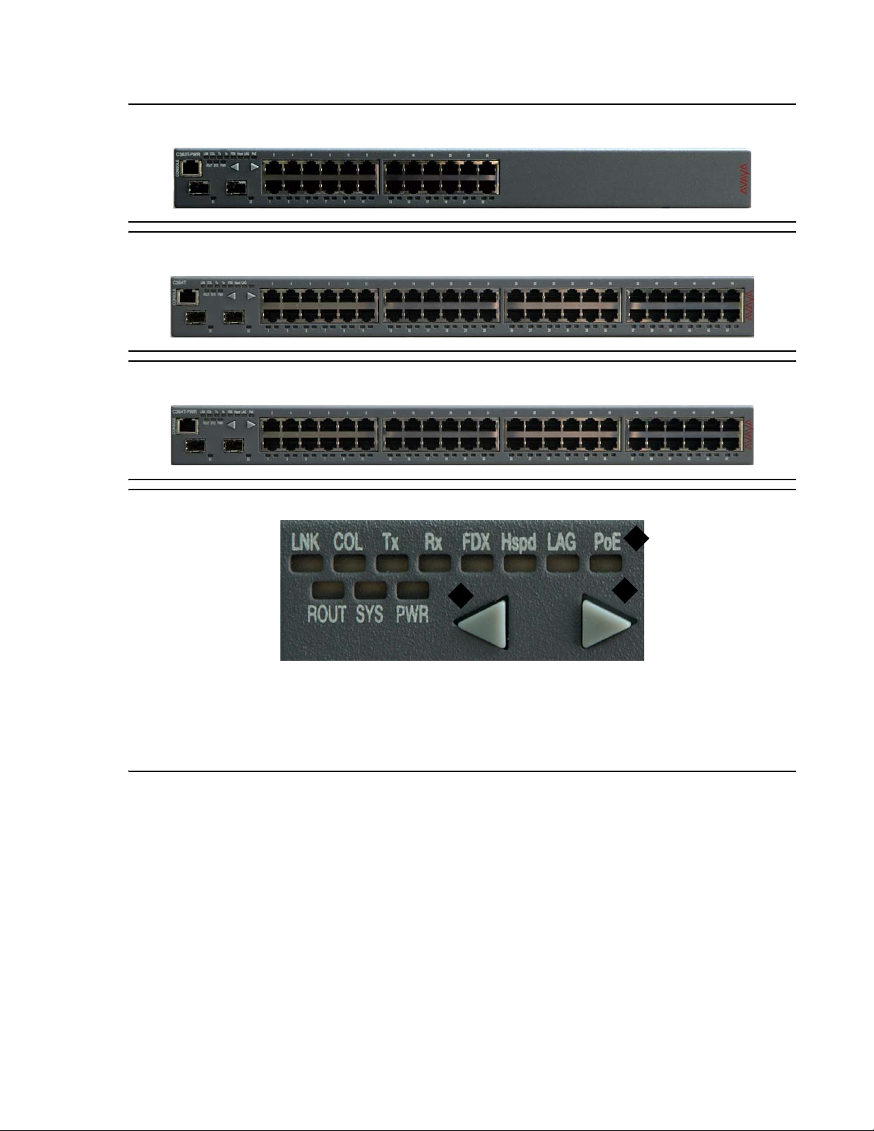
C360 Front Panels
The front panel contains LEDs, controls, and connectors. The status LEDs and control buttons
provide at-a-glance information.
The front panel LEDs consist of Port LEDs and Function LEDs. The Port LEDs display
information for each port according to the illuminated function LED. The function is selected by
pressing the left or right button until the desired parameter LED is illuminated.
For example, if the COL LED is illuminated, then all Port LEDs show the collision status of their
respective port. If you wish to select the LAG function, then press the left button until the LAG
Function LED is lit; if you then wish to select Rx then press the right button three times until the
Rx function LED lights.
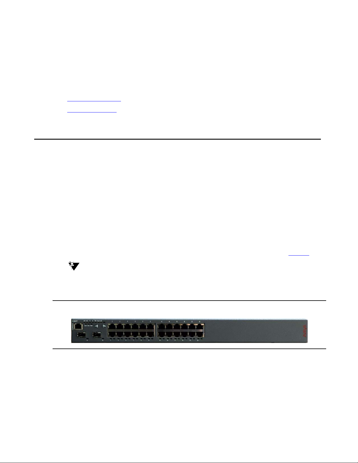
The front panels shown below includes LEDs, buttons, SFP GBIC transceiver housings,
10/100BASE-T ports and the RJ-45 console connector. The LEDs are described in Table 3
Tip:
Tip: The 10/100BASE-T ports of the C363T-PWR are numbered from 1 to 24; on the
C364T-PWR 1 to 48. The two SFP Gigabit Ethernet ports are numbered 51 and
52.
Figure 1: C363T Front Panel
.
Issue 1 July 2006 29
Page 30
Avaya C360 Front and Rear Panels
Figure 2: C363T-PWR Front Panel
Figure 3: C364T and C364T NEBS Front Panel
Figure 4: C364T-PWR Front Panel
Figure 5: C360 Function LEDs
Figure notes:
1. PoE LED on C360-PWR only
2. Left front panel button
3. Right front panel button
1
2
3
30 Installation and Configuration Guide Avaya C360 Multilayer Stackable Switches, version 4.5
Page 31

C360 Front Panels
Figure 6: Order of Function 'Parameters Selected with the Left/Right Front Panel Buttons
Starting Point
(after Power-up or Reset)
Figure notes:
1. PoE LED on C360-PWR only
Table 3: C360 Function LED Descriptions 1 of 3
LED
Description LED Status
Name
1
LAG
Left
Button
PoE
Hspd
Right
Button
LNK
COL
Tx
Rx
FDX
PWR Power Status OFF - Power is off
ON - Power is on
Blinking - Main power is down and BUPS is
active
SYS System Status OFF - Module is a slave in a stack
ON - Module is the stack master , and t he optional
Octaplane and Redundant cable(s) are either not
connected or not active.
This LED will also light in Standalone mode.
Blinking - Switch is the stack master and the
Octaplane is in redundant cable is active.
ROUT Routing Mode OFF - Layer 2 mode
ON - Router mode
1 of 3
Issue 1 July 2006 31
Page 32

Avaya C360 Front and Rear Panels
Table 3: C360 Function LED Descriptions 2 of 3
LED
Description LED Status
Name
The following Function LEDs apply to all ports
LNK Port Status OFF - Port is disabled
ON - Link is OK
Blinking - Port is enabled, but Link is down
COL Collision OFF - No collision or full-duplex port for ports 1 to
24/48; always OFF for ports 51 to 52.
ON - Collision occurred on line.
Tx Transmit to line OFF - No transmit activity
ON - Data transmitted on line from the module
Rx Receive from
OFF - No receive activity
line
ON - Data received from the line into the module
FDX Full Duplex
OFF - Half duplex mode (ports 1 to 24/48)
mode
ON - Full duplex mode (ports 1 to 24/48)
Always ON for ports 51,52 (full-duplex mode
only)
Hspd High Speed Ports 1-24/48 Ports 51,52
OFF: 10 Mbps N/A
ON: 100 Mbps 1000 Mbps
LAG Link
OFF - No LAG defined for this port
Aggregation
Group
ON - Port belongs to a LAG
(Trunking)
2 of 3
32 Installation and Configuration Guide Avaya C360 Multilayer Stackable Switches, version 4.5
Page 33

Table 3: C360 Function LED Descriptions 3 of 3
C360 Rear Panel
LED
Description LED Status
Name
PoE* Power over
Ethernet.
*C360-PWR only
Tip:
Tip: All LEDs light during a reset.
Table 4: C360 Right and Left Select buttons
OFF - PoE disabled for this port
ON - PoE is enabled and power is being supplied
to an end-station
Blinking:
● PoE enabled, but no powered device is
detected, or
● Power supply error, or
● Not enough power
3 of 3
On order to... Press...
Select the function
LED (see Table 3
Reset the switch Both Right and Left buttons together for approximately
Reset the stack Both Right and Left buttons together for five seconds. All
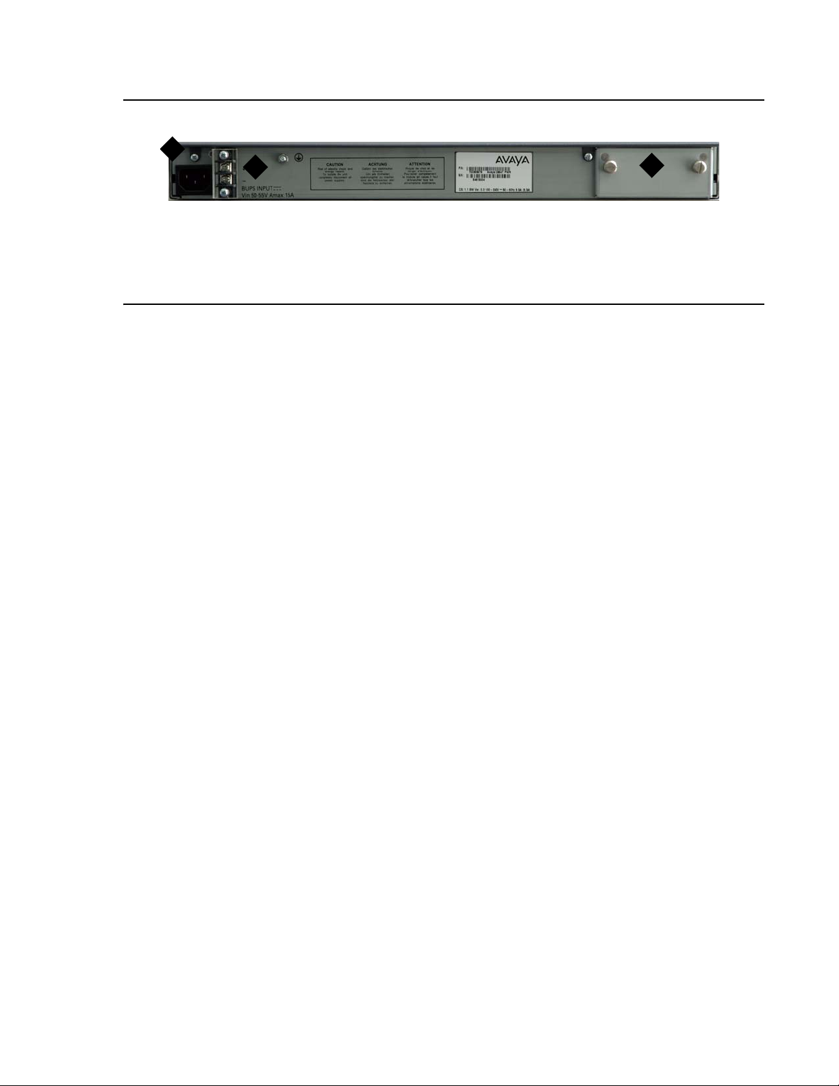
C360 Rear Panel
The C360 rear panel contains a stacking module slot, AC power input and BUPS DC input.
Note:
Note: The C/S: and SW versions on your C360 switches may differ from those shown in
Figure 7
.
Left or Right button
)
one second. All LEDs on the switch remain lit until the
procedure is complete.
LEDs on the stack remain lit until the procedure is
complete.
Issue 1 July 2006 33
Page 34
Avaya C360 Front and Rear Panels
Figure 7: C360 Rear Panel
1
2
Figure notes:
1. AC Input
2. BUPS DC Input
3. X360STK slot (shown covered)
3
34 Installation and Configuration Guide Avaya C360 Multilayer Stackable Switches, version 4.5
Page 35

Chapter 3: Installation
The C360 switch is ready to work after you complete the installation instructions described in
this chapter. After you have completed the procedures in this chapter, proceed to
Chapter 4:
The following steps are described in this chapter:
● Preparing Needed Tools
● Site Preparation
● Rack Mounting (Optional)
● Wall Mounting (Optional)
● Stacking (optional)
● Making Connections to Network Equipment
● Installing SFP GBIC Transceivers
Powering Up the Avaya C360
Preparing Needed Tools
Prepare the tools you need to mount the Replace variable w/ short product name, according to
the Table 5
:
Table 5: Mounting Tools
If you need to mount on... Prepare these tools
Rack or wall Phillips head screwdriver
Flat wall screws to fasten Replace variable w/ short
Uneven wall
product name to the wall
● 16.3" x 18.3" (415 x 465 mm) plywood
board 0.8" (20 mm) thick
wood screws
● screws to fasten the Replace variable w/
short product name to the wall
Issue 1 July 2006 35
Page 36

Installation
Site Preparation
You can mount the C360 alone or in a stack in a standard 19-inch equipment rack located in a
wiring closet or equipment room. You can build a logical stack of up to ten C360 switches.
Ensure that the location where you install your Replace variable w/ short product name fulfills
the following requirements:
● Cables are away from sources of electrical noise such as:
● radio transmitters
● broadcast amplifiers
● power lines
● fluorescent light fixtures
● Water or moisture cannot enter the chassis.
● Air can flow freely around all sides of the chassis.
● The vents on the sides of the chassis are not blocked.
● The environmental conditions match the requirements listed in Table 6.
Table 6: Environmental Requirements
Condition Acceptable values
o
Ambient temperature 32
to 104oF (0o to 40oC)
Relative humidity 5-95% non-condensing
Weight support 10.8-15 lbs (4.9-6.8 kg)
36 Installation and Configuration Guide Avaya C360 Multilayer Stackable Switches, version 4.5
Page 37

● The power source matches the specifications shown in Table 7:
Table 7: Power Requirements
AC Input voltage 100 to 240 VAC, 50 to 60 Hz
Power consumption
● C363T
● C363T-PWR
● C364T
● C364T (NEBS)
● C364T-PWR
● 60 W
● 420 W
● 90 W
● 90 W
● 760 W
AC Input current
● C363T
● C363T-PWR
● C364T
● C364T (NEBS)
● C364T-PWR
● 1.3 A
● 4.2 A
● 1.3 A
● 1.3 A
● 7.6 A
Rack Mounting (Optional)
DC Input voltage
(C364T NEBS only)
DC Input current
(C364T NEBS only)
Rack Mounting (Optional)
The C360 chassis fits in most standard 19-inch racks. It is 1U (44.45 mm, 1.75”) high.
You can mount the Avaya C360 in a standard 19" rack either in “front-mount” or “mid-mount”
positions using the brackets supplied with the chassis.
The brackets are symmetric: you can fix either bracket on either side.
Figure 8
shows the two available rack mounting positions:
-36 to -60 VDC
2 A
Issue 1 July 2006 37
Page 38

Installation
Figure 8: Front and Mid-Mount Positions
7.9"
(200 mm)
3
Front
Figure notes:
1. Equipment rack 2. Mid-mount position 3. Front mount position
Before you Install the C360 in a Rack
● When installing C360 in a rack, ensure that the equipment is positioned such that it will not
cause the rack to become unstable or tip over.
1
2
● Ensure that the combination of equipment in the rack will not cause an overload or
overcurrent condition on the power strip being used and/or the customer's branch circuit.
● The C360 units weigh a maximum of 15 pounds (6.8 kg). Be careful when installing or
removing the C360 product from the rack.
● If a power strip is being used in the rack, ensure that it has a reliable earth connection. If
the C360 equipment will be plugged directly into a wall outlet, ensure that there is a
reliable ground connection at the outlet.
● Ensure that the internal rack ambient temperature is within the operating specification
limits of the C360.
● Ventilation for the C360 is from side to side. Ensure that there is adequate space on each
side of the C360 equipment when installed in the rack to allow sufficient airflow.
Place the C360 in the rack as follows:
1. Position the brackets on the C360 as shown in Figure 9
, Figure 10 or Figure 11, according
to the model.
38 Installation and Configuration Guide Avaya C360 Multilayer Stackable Switches, version 4.5
Page 39

Figure 9: C360 Rack Mounting (except C364T NEBS)
1
Figure notes:
1. Front mount position 2. Mid-mount position
Figure 10: C360 Rack Mounting - Front Mount (C364T NEBS only)
Rack Mounting (Optional)
2
Figure 11: C360 Rack Mounting - Mid Mount (C364T NEBS only)
2. Firmly attach the brackets to the chassis with the screws provided.
Issue 1 July 2006 39
Page 40

Installation
-Use four screws to attach each bracket to the switch for non-NEBS switches.
-Use eight screws to attach each bracket to the switch for the C364T NEBS switch.
3. Position the switch in the rack.
4. Fasten the switch in the rack with the screws provided.
Wall Mounting (Optional)
Note:
Note: Do not mount the C364T NEBS on a wall.
You can fix the C360 to the wall as follows:
!
CAUTION:
CAUTION: Ensure that the wall and screws can support the weight of the C360 and any
installed modules. The maximum weight of a C360 switch is 15 lb. (6.8 kg)
!
CAUTION:
CAUTION: You must mount the C360 with the ventilation holes facing left and right and the
front panel facing up.
1. Attach the brackets to the C360 as shown in Figure 12
.You can attach the brackets to face
either the top or the bottom of the unit, depending whether you want the top panel or bottom
panel of the unit to face the wall.
Figure 12: C360 Wall Mounting
2. Place the unit on the wall.
3. Secure the unit to the wall using two screws on each side. Do not overtighten the screws.
40 Installation and Configuration Guide Avaya C360 Multilayer Stackable Switches, version 4.5
Page 41

!
CAUTION:
CAUTION: Ensure that ventilation holes are not obstructed.
Stacking (optional)
There are two main steps for creating stacks:
1. Installing the X360STK Stacking Module
2. Inter-Connecting Switches
Installing the X360STK Stacking Module
!
CAUTION:
CAUTION: C360 switches and stacking modules contain components sensitive to
electrostatic discharge. Touching the circuit boards unless instructed to do so
may damage them.
Stacking (optional)
!
PRECAUCIÓN:
PRECAUCION: El switch C360 y sus módulos de ampliación contienen componentes sensibles a
descargas electrostáticas. Tocar las tarjetas sin autorización del persona l técnico
puede dañarlas.
!
CAUTION:
CAUTION: Do not leave the stacking slots open. Cover empty slots using the blanking plates
supplied.
!
PRECAUCIÓN:
PRECAUCION: No deje las aberturas de ampliación abiertas. Cubrir las aberturas vacias con las
placas bloqueadoras proporcionadas con el equipo.
To install the stacking module in the C360:
1. Remove the existing stacking module or blanking plate from the back of the C360 switch.
2. Insert the stacking module gently into the slot, ensuring that the PCB (printed circuit board)
is aligned with the guide rails.
3. Press the module in firmly until it is completely inserted into the Avaya C360.
Note:
Note: Ensure that the screws on the module are properly aligned with the holes in the
chassis before tightening them.
Issue 1 July 2006 41
Page 42

Installation
4. Tighten the two screws on the side panel of the stacking module by turning the knurled
knobs clockwise.
Inter-Connecting Switches
Tip:
Tip: Y ou may st ack the C360 with the G700, P333T-PWR, P332G-ML or P3 32GT-ML.
Please refer to Appendix A:
Note:
Note: The two ends of the Octaplane cable terminate with different connectors. Each
connector can only be connected to its matching port.
The following cables are used to connect stacked switches:
● Short Octaplane cable (X330SC) - ivory-colored, used to connect adjacent switches
(Catalog No. CB0223) or switches separated by a BUPS unit. This cable is 30 cm. long.
● Long/Extra Long Octaplane cable (X330LC/X330L-LC) - ivory-colored, used to connect
switches from two different physical stacks, or switches separated by a BUPS unit
(Catalog No. CB0225/CB0270). The long cable is 2 m long; the extra-long cable is 8 m
long.
Mixed Stacks for further information on mixed st acks.
● Redundant/Long Redundant Octaplane cable (X330RC/X330L-RC) - black, used to
connect the top and bottom switches of a stack (Cat alog No. CB0222/CB0269). This cable
is 2 m long.
Tip:
Tip: You may use the same cables with P330 and P330-ML switches.
To connect stacked switches:
Tip:
Tip: When adding a switch to an existing stack, first connect the stacking cables and
then power up the module.
To connect stacked switches:
1. Plug the light grey connector of the Short Octaplane cable into the port marked “to upper
unit" of the bottom C360 switch.
2. Plug dark grey connector of same Short Octaplane cable to the port marked “to lower unit"
in the unit above. The connections are illustrated in Figure 13
3. Repeat Step 1and Step 2 until you reach the top switch in the stack.
.
42 Installation and Configuration Guide Avaya C360 Multilayer Stackable Switches, version 4.5
Page 43

Stacking (optional)
4. If you wish to implement stack redundancy, use the Redundant Cable to connect the port
marked “to lower unit" on the bottom switch to the port marked “to upper unit"" on the top
switch of the stack.
5. Power up the added modules.
!
CAUTION:
CAUTION: Do not cross connect two switches with two Octaplane (light-colored) cables. If
you wish to cross-connect for redundancy , use one light-colored Oct aplane cable
and one black redundancy cable. The black cable will then serve as a redundant
connection.
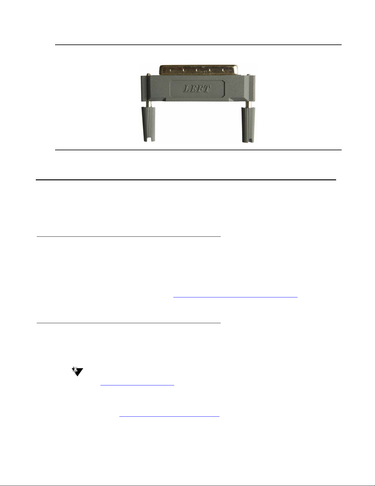
!
CAUTION:
CAUTION: To prevent EMI, cover any unused ports on the stacking modules using the grey
plugs provided. Insert the plug labelled "left" into the lower port; insert the plug
labelled "right" into the upper port. See Figure 14
.
Tip:
Tip: You can build a logical stack of up to ten C360 switches. If you do not wish to
stack all the switches in a single rack, use long Octaplane cables to connect the
two physical stacks.
Figure 13: C360 Stacking Connections
Issue 1 July 2006 43
Page 44
Installation
Figure 14: Plug for Unused Stacking Ports
Making Connections to Network Equipment
This section describes the physical connections that you can make between the C360 switch
and other network equipment.
Prerequisites
Make sure you have the following before attempting to connect network equipment to the C360:
● A list of network equipment to be connected to the C360, detailing the connector types on
the various units
● All required cables, as specified in Connecting Cables to Network Equipment. Appropriate
cables are available from your local supplier.
Connecting Cables to Network Equipment
C360 switches include the following types of ports (according to the speed and standard they
support): 10/100BASE-T (PoE on the C360-PWR) and SFP GBIC
Tip:
Tip: See http://support.avaya.com for a list of compatible NICs.
To connect the cables:
1. If you are using an SFP GBIC (Small Form Factor Plugable Gigabit Interface Converter)
transceiver, see Installing SFP GBIC Transceivers
44 Installation and Configuration Guide Avaya C360 Multilayer Stackable Switches, version 4.5
.
Page 45

2. For all other ports, connect an Ethernet copper cable (not supplied) directly to th e ports. The
copper ports can operate with 2 pair (4 wire) or 4 pair (8 wire) CAT 5 Ethernet cables
(crossed or straight). The maximum cable length is 100 m (328 ft.).
3. Connect the other end of the cable to the Ethernet port of the PC, server, router,
workstation, switch, hub, or other end device.
4. Check that the appropriate link (LNK) LED lights up.
Installing SFP GBIC Transceivers
The SFP GBIC (Gigabit Interface Converter) have been tested for use with the C360 Gigabit
Ethernet ports. For a list of approved SFP GBIC transceivers, see: http://support.avaya.com
SFP GBIC transceivers are hot-swappable.
Installing SFP GBIC Transceivers
Safety Information
!
CAUTION:
CAUTION: You must operate the SFP GBIC transceivers under recommended operating
conditions, as specified for each transceiver.
!
WARNING:
WARNING: The use of optical instruments with this product will increase eye hazard.
!
ADVERTENCIA:
ADVERTENCIA: El uso de instrumentos ópticos en este producto aumentará el riesgo de peligro
para la vista.
Usage Restriction
When a SFP GBIC transceiver is inserted in the module but is not in use, protect the Tx and Rx
ports with an optical connector or a dust plug.
!
CAUTION:
CAUTION: Use only approved SFP GBIC transceivers. All approved SFP GBIC transceivers:
1) are 3.3V. Do not insert a 5VSFP GBIC.
2) use Serial Identification. Do not use a GBIC that utilizes Parallel
Identification.
Issue 1 July 2006 45
Page 46
Installation
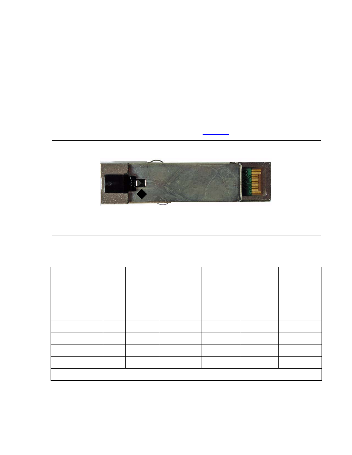
Installing and Removing a SFP GBIC Transceiver
The SFP GBIC transceiver is fastened using a snap-in clip.
To install the SFP GBIC transceiver:
● Insert the transceiver (take care to insert it the right way up) until it clicks in place.
● Refer to Copper GBIC Transceiver Installation Notes on page 47 if you are installing a
copper GBIC transceiver.
To remove the SFP GBIC transceiver:
1. Press the clip on the base of the transceiver see Figure 15
Figure 15: Clip Location on Base of Transceiver
.
1
Figure notes:
1. Transceiver clip location
2. Pull the transceiver out.
Table 8: Gigabit Fiber Optic Cabling 1 of 2
Gigabit
Interface
Fiber
Type
Diameter
(µm)
Modal
Bandwidth
(MhzKm)
Maximum
Distance
(m)
for the location.
Minimum
Distance
(m)
Wavelength
(nm)
1000BASE-SX MM 62.5 160 220 2 850
1000BASE-SX MM 62.5 200 275 2 850
1000BASE-SX MM 50 400 500 2 850
1000BASE-SX MM 50 500 550 2 850
1000BASE-LX MM 62.5 500 550 2 1,310
1000BASE-LX MM 50 400 550 2 1,310
46 Installation and Configuration Guide Avaya C360 Multilayer Stackable Switches, version 4.5
1 of 2
Page 47

Table 8: Gigabit Fiber Optic Cabling 2 of 2
Installing SFP GBIC Transceivers
Gigabit
Interface
1000BASE-LX SM 9 N/A 10,000 2 1,310
1000BASE-ELX SM 9 N/A 70,000 10,000 1,550
Fiber
Type
Diameter
(µm)
Modal
Bandwidth
(MhzKm)
Copper GBIC Transceiver Installation Notes
Before installing a copper SFP transceiver, ensure that auto-negotiation is enabled for the
transceiver ports. You should also ensure that the auto-negotiation is enabled for the port at the
other end of the link:
1. Use the show port command to check the auto-negotiation status of the tra nsceiver port s.
2. Use the set port negotiation <module>/<port> enable command to enable
auto-negotiation if necessary.
Maximum
Distance
(m)
Minimum
Distance
(m)
Wavelength
(nm)
2 of 2
Issue 1 July 2006 47
Page 48

Installation
48 Installation and Configuration Guide Avaya C360 Multilayer Stackable Switches, version 4.5
Page 49

Chapter 4: Powering Up the Avaya C360
This chapter describes the procedures for powering up C360 switches.
Connecting the C360 to the main electrical supply provides power to the switch and for Power
over Ethernet (PoE).
!
WARNING:
WARNING: To isolate the switch completely , you must disconnect all power connections (AC
plug, DC power and DC BUPS power).
!
ADVERTENCIA:
ADVERTENCIA: Para aislar el equipo totalmente desconecte todas las conexiones de energía
(Enchufe de CA, fuente de CC y fuente de CC del BUPS)
Figure 16: C360 Back Panel
1
Figure notes:
1. AC Input
2. BUPS DC Input
2
Issue 1 July 2006 49
Page 50

Powering Up the Avaya C360
Connecting to an AC Power Supply
AC Power Cable
The C360 switch is supplied with a North American power cordset. Below are guidelines that
should be used when obtaining and/or defining a different cordset to be used with the C360.
The cordsets should be further verified for safety requirements of the p articular application by a
safety and regulatory professional:
For 200 to 240V applications, the cord must be VDE Certified or Harmonized (HAR), rated
250V, 3-conductor (3rd wire ground), 1.0 mm
2
minimum conductor size. The cord is to be
terminated at one end to a VDE Certified/CE Marked IEC 60320, sheet C13 type connector
rated 10A, 250V and the other end to a 3-conductor grounding type attachment plug rated at a
minimum of 10A, 250V and a configuration specific for the region/country in which it will be
used. The attachment plug must bear the safety agency certifications mark(s) for the region/
country of installation.
● For North American installations, a UL Listed and CSA Certified 15A branch circuit
protective device must be provided in the building AC mains wiring installation for branch
circuit protection.
● For other installations, a suitable and certified 10A branch protective device must be
provided in the building AC mains wiring installation.
Tip:
Tip: You may order certain cordsets from Avaya.
The C360 is rated 100-240 V~, 50-60 Hz. The maximum input current depends on the specific
C360 model
1. Insert the AC power cord into the power inlet in the back of the unit.
2. Insert the AC plug into the AC power supply.
● The unit powers up.
● The C360 performs a self test procedure.
3. Connect the BUPS DC power supply (if applicable).
50 Installation and Configuration Guide Avaya C360 Multilayer Stackable Switches, version 4.5
Page 51

Connecting to a DC Power Source (C364T NEBS Only)
Connecting to a DC Power Source (C364T NEBS Only)
The C364T NEBS is rated -36 to -60 VDC, 2A.
!
CAUTION:
CAUTION: A UL-Listed and CSA-Certified branch circuit protective device of up to 20A must
be provided in the building DC mains wiring installation for branch circuit
protection.
!
CAUTION:
CAUTION: Always connect the ground wire first and disconnect it last.
Figure 17: Avaya C360 DC Input Terminal Block
1
2
3
Figure notes:
1. Protective plastic cover 2. BUPS DC input terminals 3. Grounding post
● The terminals are marked with , “+” and “-“.
● The size of the two screws in the terminal block is M4.
● The pitch between each screw is 9.5mm.
4. Remove the protective plastic cover over the DC inputs by unscrewing the two Phillips
screws.
!
WARNING:
WARNING: The conductors to be used for connecting the DC power supply to the C360 must
be UL Recognized and CSA Certified and be a minimum of 16 AWG or have a
cross-sectional area of 1.0mm
!
ADVERTENCIA:
ADVERTENCIA: Los conductores que se utilizarán para conectar la fuente de alimentación
2
.
externa con el C360 deben ser Reconocidos por UL, Certificados por CSA y ser
como mínimo de 16 AWG o tener un área de sección transversal de 1.0 mm
2
.
5. Connect the power cable to the terminals on the C360 and to the external DC power supply
in the following sequence:
1. Ground wire to grounding post
Issue 1 July 2006 51
Page 52

Powering Up the Avaya C360
2. Positive to positive
3. Negative to negative
!
WARNING:
WARNING: Make sure that you connect the cables between the C360 and the external power
supply correctly:
1. Positive to positive
2. Negative to negative
!
ADVERTENCIA:
ADVERTENCIA: Asegúrese que las polaridades de los cables entre el C360 y la fuente de
alimentación externa estén conectados correctamente:
● Positivo ("+") a Positivo ("+")
● Negativo ("-") a Negativo ("-")
6. Replace the plastic cover by aligning the holes with the screw receptacles and replacing the
two Phillips screws.
52 Installation and Configuration Guide Avaya C360 Multilayer Stackable Switches, version 4.5
Page 53

Connecting a BUPS
Note:
Note: You cannot connect the C360 to a DC power supply and BUPS simultaneously.
If you deploy a BUPS with the C360, the Powerstax (formerly known as APC (Advanced Power
Conversion PLC)) Front End AC-DC Power Shelf (model R2400A111) with Powerstax 800W
PSUs (models A0800-085-545-CA1) are to be used.The applied voltage at the C360 BUPS DC
terminal block should be from 52 to 55 VDC.
The Isolation must be 1500V RMS with respect to protective ground
Figure 18: C360 BUPS DC Input Terminal Block
Connecting a BUPS
1
2
3
Figure notes:
1. Protective plastic cover
2. BUPS DC input terminals
3. Earthing post
● The terminals are marked "+" and “-“.
● The size of the two screws in the terminal block is M4.
● The pitch between each screw is 9.5mm.
1. Remove the protective plastic cover over the BUPS DC inputs by unscrewing the two
Phillips screws.
!
WARNING:
WARNING: The conductors to be used for connecting the BUPS to the C360 must be UL
Recognized and CSA Certified and be a minimum of 16 AWG or have a
cross-sectional area of 1.0 mm
!
ADVERTENCIA:
ADVERTENCIA: Los conductores que se utilizarán para conect ar la BUPS co n el C360 deben ser
2
.
Reconocidos por UL, Certificados por CSA y ser como mínimo de 16 AWG o
tener un área de sección transversal de 1.0 mm
2
.
Issue 1 July 2006 53
Page 54

Powering Up the Avaya C360
2. Connect the power cable to the terminals on the C360 and then external DC power supply.
!
WARNING:
WARNING: Make sure that you connect the cables between the C360 and the external power
supply correctly:
● Positive (“+") to positive (“+")
● Negative (“-") to negative (“-")
!
ADVERTENCIA:
ADVERTENCIA: Asegúrese que las polaridades de los cables entre el C360 y la fuente de
alimentación externa estén conectados correctamente:
● Positivo ("+") a Positivo ("+")
● Negativo ("-") a Negativo ("-")
3. Replace the plastic cover by aligning the holes with the screw receptacles and replacing the
two Phillips screws.
Supplemental Earthing of the C360 (Optional)
When connecting a BUPS to the C360, you must also connect a ground wire to the ground stud
provided on the rear of the unit. This ground conductor must be green/yellow, a minimum of 16
AWG and be terminated with a lug that is suitable f or the M4 stud provided. The other en d of the
ground conductor is to be terminated to a suitable building ground point such as a cold water
pipe.
54 Installation and Configuration Guide Avaya C360 Multilayer Stackable Switches, version 4.5
Page 55
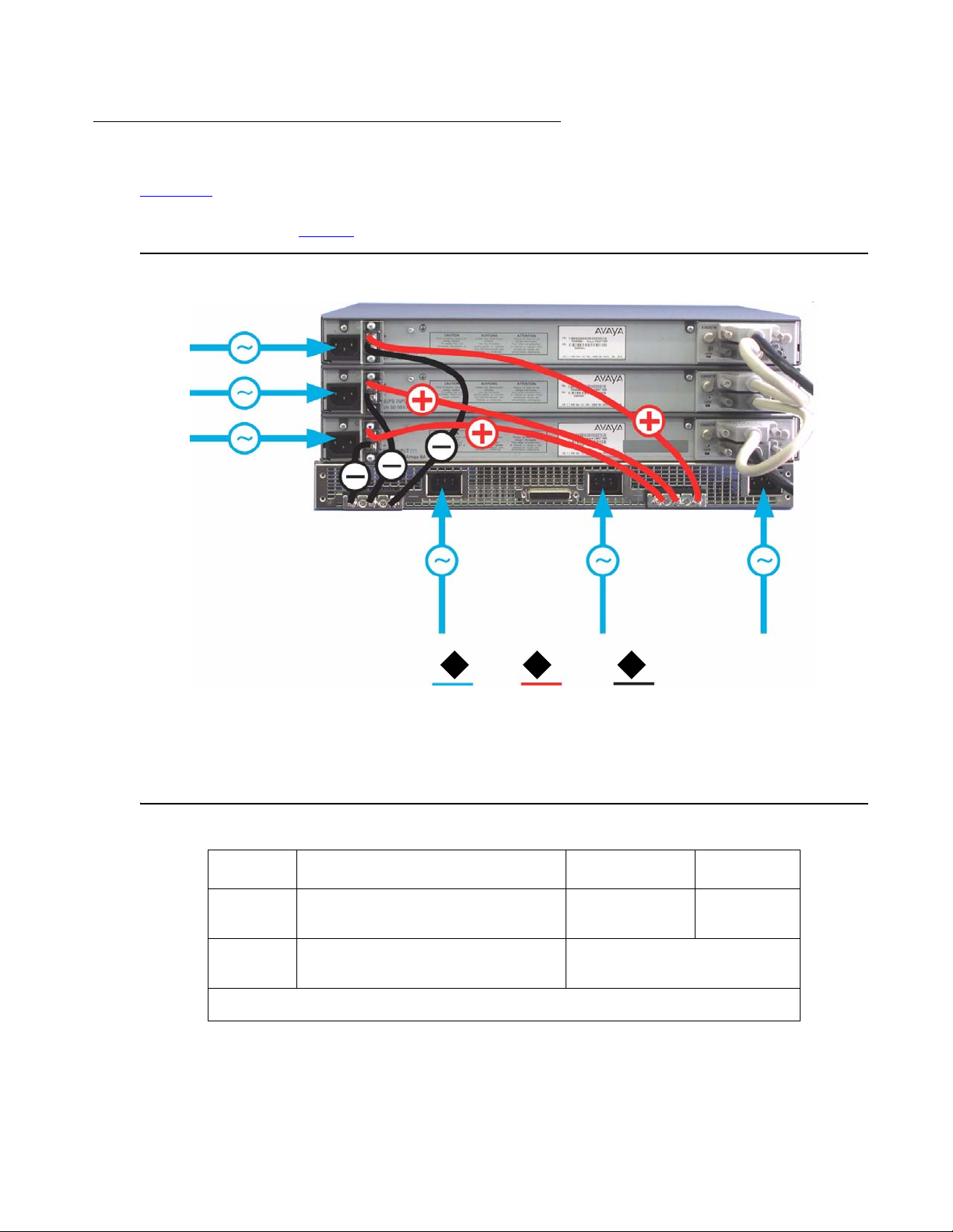
Sample Backup Power Supply Scheme
Figure 19 shows a connection example for a stack of three C363T-PWR switches. This
configuration provides power supply redundancy and up to 305 W of inline power per
C363T-PWR switch. Table 9
Figure 19: Sample Scheme
lists the equipment required for this scenario.
Connecting a BUPS
Figure notes:
1. AC power
2. BUPS DC input (+)
3. BUPS DC input (-)
Table 9: Required Equipment (C363T-PWR Scheme) 1 of 2
Quantity Description Material code PEC Code
3 C363T-PWR Power over
1 Powerstax Front End AC-DC
2 31
700305881
Ethernet Stackable Switch
R2400A111*
Power Shelf
1 of 2
Issue 1 July 2006 55
Page 56

Powering Up the Avaya C360
Table 9: Required Equipment (C363T-PWR Scheme) 2 of 2
Quantity Description Material code PEC Code
2 Powerstax 800W PSUs (see
A0800-085-545-CA1*
"Budgeting Power" for details)
3 X360STK Octaplane stacking
700305899
module
1 X330RC Redundant Octaplane
108563453 4705-065
stacking cable
2 X330SC Short Octaplane
108592445 4705-067
stacking cable**
6 Power cables to connect
N/A
Powerstax Power Shelf to
C360-PWR switches.* (16AWG/
1.0 mm
2
or thicker cable; with
terminals suitable for M4 screws)
2 of 2
* These items are not available from Avaya.
** You can also use the long Octaplane stacking cables. See the “Avaya X360STK Installation Guide" for
information.
56 Installation and Configuration Guide Avaya C360 Multilayer Stackable Switches, version 4.5
Page 57

Budgeting Power
Note:
Note: One Powerstax 800W PSU provides enough power for a sta ck of ten C363T an d/
or C364T switches.
When deciding how many 800W PSUs to install in the Powerstax external DC power shelf, you
need to take into account the configuration of the powerinline external power parameter in the
C360-PWR switch (set using the set powerinline external power CLI command).
Refer to Table 10
and Table 11 for guidelines:
Table 10: Budgeting Power - C363T-PWR
Connecting a BUPS
No. of Powerstax
PSUs
No. of C363T-PWR switches
supported
Power requirement: 350W
12
24
36
Table 11: Budgeting Power - C364T-PWR
No. of Powerstax
PSUs
No. of C364T-PWR switches
supported
Power requirement = 600W
11
22
34
If you set the powerinline external power parameter to other values, you need to recalculate the
number of switches supported accordingly.
Issue 1 July 2006 57
Page 58

Powering Up the Avaya C360
Post-Installation
The following indicate that you have performed the installation procedure correctly:
Table 12: Post-Installation Indications
Procedure Indication Troubleshooting
Information
Powering the
C360
● All front panel function LEDs
illuminate briefly.
Switch does not
power up on
page 201
- If the PWR LED blinks once every 1
second, then the BUPS is active
and the main PSU is down.
● The LINK, SYS and PWR LEDs light
● The port LEDs flash
Creating
stacks
The LED next to the appropriate connection
(“Cable to upper unit" or “Cable to lower
unit") is lit.
Stacking not
functioning on
page 203
If you do not receive the appropriate indication, please refer to Chapter 12:
Installation.
Troubleshooting the
58 Installation and Configuration Guide Avaya C360 Multilayer Stackable Switches, version 4.5
Page 59

Chapter 5: Establishing Switch Access
This chapter describes various methods for accessing the C360 CLI and logging in with the
appropriate security level:
C360 CLI
● CLI Architecture
● Security Levels
● Entering the CLI
Establishing Connections
● Establishing a Console Connection
● Assigning C360 IP Stack Address
● Establishing a Telnet Connection
● Establishing an SSH Connection
● Establishing Access to Other Entities in the Stack (C360 Sessions)
● Establishing a Modem (PPP) Connection
● SNMP Support
Security
● RADIUS
● Recovery Password
● Allowed Managers
● Allowed Protocols
Issue 1 July 2006 59
Page 60

Establishing Switch Access
CLI Architecture
The C360 stack supports both Layer 2 switching and Layer 3 switching.
The C360 CLI includes two CLI entities to support this functionality.
● The Switch CLI entity is used to manage Layer 2 switching of the entire stack. CLI
commands for managing Layer 2 switching are described in the Reference Guide for the
Avaya C360 Converged Stackable Switch, 10-300506.
● The Router CLI entity is used to manage Layer 3 switching of a single module. CLI
commands for managing Layer 3 switching are described in the Reference Guide for the
Avaya C360 Converged Stackable Switch, 10-300506.
To switch between the entities, use the session command.
Security Levels
There are three security access levels - User, Privileged, and Supervisor.
● The User level ('read-only') is a general access level used to show system parameter
values.
● The Privileged level ('read-write') is used by site personnel to access stack configuration
options.
● The Supervisor level ('administrator') is used to define user names, passwords, and
access levels of up to 10 local CLI users, configure SNMPv1 community, configure
SNMPv3, configure RADIUS authentication and control access protocols to the device.
Tip:
Tip: If you wish to define more than ten users per switch, or accounts for a user on
multiple switches, use RADIUS (Remote Authentication Dial-In User Service).
A login name and password are always required to access the CLI and the commands. The
login name, password, and access-type (i.e., security level) for a user account are established
using the username command.
Switching between the entities does not effect the security level since security levels are
established specifically for each user. For example, if the operator with a privileged security
level in the Switch entity switches to the Router entity, the privileged security level is retained.
Tip:
Tip: If you wish to increase security, you can disable SNMPv1 and allow only
SNMPv3.
60 Installation and Configuration Guide Avaya C360 Multilayer Stackable Switches, version 4.5
Page 61

Tip:
Tip: The Web management passwords are the same as those of the CLI. If you
change the passwords of the CLI then those passwords become active for Web
management as well.
Entering the Supervisor Level
The Supervisor level is the level in which you first enter C360 CLI and establish user names for
up to 10 local users. When you enter the Supervisor level, you are asked for a Login name.
Type root as the Login name and the default password root (in lowercase letters):
Welcome to C360
Login: root
Password:****
Password accepted.
C360-N(super)#
Security Levels
Defining new local users
Define new users and access levels using the following command in Supervisor Level:
Table 13: Local User CLI Commands
In order to... Use the following command...
Add a local user account and
configure a user (name,
password and access level)
To remove a local user account no username
Display the username and
access type for all users on the
switch
Exiting the Supervisor Level
To exit the Supervisor level, use the exit CLI command.
username
show username
Issue 1 July 2006 61
Page 62

Establishing Switch Access
Entering the CLI
To enter the CLI, enter your username and password. Your access level is indicated in the
prompt as shown in Table 14
Table 14: CLI Prompts (Layer 2)
Level Prompt
User (read-only) C360-N>
Privileged (read-write) C360-N#
Supervisor C360-N(super)#
Configure C360-N(configure)#
.
Establishing a Console Connection
This section describes the procedure for establishing switch access between a termin al and the
C360 switch over the serial port provided on the front panel of the C360 (RJ-45 connector
labeled "Console"). For information on the console port pin assignments, refer to Console Pin
Assignments on page 230.
Figure 20: C360 Console Port
1
Figure notes:
1. Console Port
62 Installation and Configuration Guide Avaya C360 Multilayer Stackable Switches, version 4.5
Page 63

Establishing a Console Connection
1. Use the serial cable supplied to attach the RJ-45 console connector to the Console port of
the master C360. Connect the DB-9 connector to the serial (COM) port on your PC/terminal.
- The master C360 is indicated by the SYS LED being ON.
2. Ensure that the serial port settings on the terminal are:
● 9600 baud
● 8 bits
● 1 stop bit
● no parity.
- If you reset or powered up the switch after connecting and configuring the terminal,
Welcome to C360 appears followed by the Login Name prompt.
- If the login prompt does not appear, press a key on the terminal.
3. Enter the default login: root.
- The Password prompt appears
4. Enter the user level password: root.
- You can now establish a connection to the Router or the Master switch (indicated when
the SYS front panel LED is ON) using the Session commands and begin the
configuration of module, stack, or router parameters.
Issue 1 July 2006 63
Page 64

Establishing Switch Access
Assigning C360 IP Stack Address
Note:
Note: All C360 switches are shipped with the same default IP address. You must
change the IP address of the master C360 switch in a stack in order to guarantee
that the stack has its own unique IP address in the network.
The network management station or a workstation running a Telnet client can establish
communications with the stack once this address had been assigned and the stack has been
inserted into the network. Use the CLI to assign the C360 stack an IP address and net mask.
To assign a C360 IP stack address:
1. Establish a serial connection by connecting a terminal to the master C360 switch of the
stack.
2. When prompted for a Login Name, enter the default name root
3. When you are prompted for a password, enter the password root. You are now in
Supervisor Level.
4. At the prompt, type:
set interface inband <vlan> <ip_address> <netmask>
Replace <vlan>, <ip_address> and <netmask> with the VLAN,
IP address, and net mask of the stack.
5. Press Enter to save the IP address and net mask.
6. At the prompt, type reset. Type y and press Enter to reset the sta ck. After the Reset, log in
again as described above.
- At the prompt, type set ip route <dest> <gateway> and replace <dest> and
<gateway> with the destination and gateway IP addresses.
64 Installation and Configuration Guide Avaya C360 Multilayer Stackable Switches, version 4.5
Page 65

Establishing a Telnet Connection
Perform the following steps to establish a Telnet connection to the C360 for configuration of
Stack or Router parameters. You can Telnet the Stack Master IP address:
1. Connect your station to the network.
2. Verify that you can communicate with the C3 60 by ping ing the IP of the C360. If there is no
response using ping, check the IP address and default gateway of both the C360 and the
station.
Tip:
Tip: The C360 default IP address is 149.49.32.134 and the default subnet mask is
255.255.255.0.
3. From the Microsoft Windows taskbar of your PC click Start and then Run (or from the DOS
prompt of your PC), then start the Telnet session by typing: telnet <C360_IP_address>
For example: telnet 149.49.32.134
4. If the IP Address in the Telnet command is the IP address of the stack, then connection is
established with the Switch CLI entity of the Master module.
Establishing a Telnet Connection
● The "Welcome to C360" screen appears
5. Enter the default name root at the Login name prompt.
6. Enter the User Level password root in lower case letters (do not use uppercase letters) at
the Password prompt.
● The User level prompt will appear when you have established communications with the
C360.
You can now configure the C360 stack and change its IP address.
Issue 1 July 2006 65
Page 66

Establishing Switch Access
Establishing an SSH Connection
Introduction to SSH
SSH (Secure Shell) protocol is a security protocol that enables establishing a remote session
over a secured tunnel, also called a remote shell. SSH accomplishes this by creating a
transparent encrypted channel between the local and remote devices. In addition to remote
shell, SSH also provides secure file transfer between the local and remote devices.
SSH protocol currently has 2 versions, SSH1 and SSH2. SSH2 provides better security
protection, key distribution services, and public key certificates than SSH1. SSH2 also has
modular architecture which enables extension authentication and encryption techniques
superior to SSH1. The OpenSSH package that Avaya uses for SSH implementation only
supports SSH2.
SSH uses password authentication.
A maximum of two SSH sessions can be active per router in the stack, with two additional active
SSH sessions per stack. For example, if a stack contains three router modules, a maximum of
eight SSH sessions can be active on the stack.
The C360 agent reports SSH sessions opened to it. In addition, each router module report s t he
SSH sessions opened to its router interface. You can disconnect selected SSH sessions.
The SSH session-establishment process is divided into the following stages, as shown in
Figure 21
:
SSH client connection:
To connect the SSH client:
1. The C360 and the SSH client initiate protocol handshake by exchanging the version
number and list of supported ciphers. This step is completed by agreement on the cipher to
be used for SSH secure tunnel. In addition, the client sends the C360 a unique session id
used to prevent replay attack.
2. The Diffie-Hellman protocol is then used to setup the shared session key. During this step,
the client and C360 exchange the DH (Diffie-Hellman) p arameters, i.e., the prime nu mber p
and the generator number g used by each party for deriving its private and public keys.
3. The client sends to C360 min., max and preferred values for p and the C360 sends client p
and g values. In response, the client uses them to derive its DH private key x and its DH
public key values by exponentiation of g with x, e = (g^x)mod p and sends the value e to the
C360
66 Installation and Configuration Guide Avaya C360 Multilayer Stackable Switches, version 4.5
Page 67

Establishing an SSH Connection
4. The C360 derives its DH private key y and its DH public key f=(g^y)mod p, and sends the f
value to the client, its public host key and the digital signature calculated for all values
exchanged so far including f and public host key. The C360 uses DSA cipher and its host
private key to calculate the signature.
5. The SSH client verifies the C360 identity. It checks the C360 host public key validity against
the ~/.ssh/known_host file. This is the prompt that user receives if he or she connects to an
unknown SSH server. It checks the known_hosts file for the host key offered by the server
and prompts if it is not there or if it has changed
6. The SSH client verifies digital signature by decrypting it with DSA and the C360 host public
key. This and the step above are essential to prevent a "man-in-the middle" attack by
someone taking the C360 identity.
7. Using combination of each other public keys and their own private keys both parties now to
calculate Diffie-Hellman shared secret. C360 calculate the shared secret K=f^x mod p and
the client calculates K=e^ymod p. Both end up with the same value because of
commutativity of exponentiation. The shared key is never sent on wire ensurin g it s secrecy.
The shared session key used then for deriving the TDES symmetric key. All messages
exchanged between the parties from this point are encrypted with TDES using the derived
TDES key.
User Authentication
Before any data is transferred, the C360 requires the client to supply a user name and static
password. This authenticates the user on the client side to the C360.
Issue 1 July 2006 67
Page 68
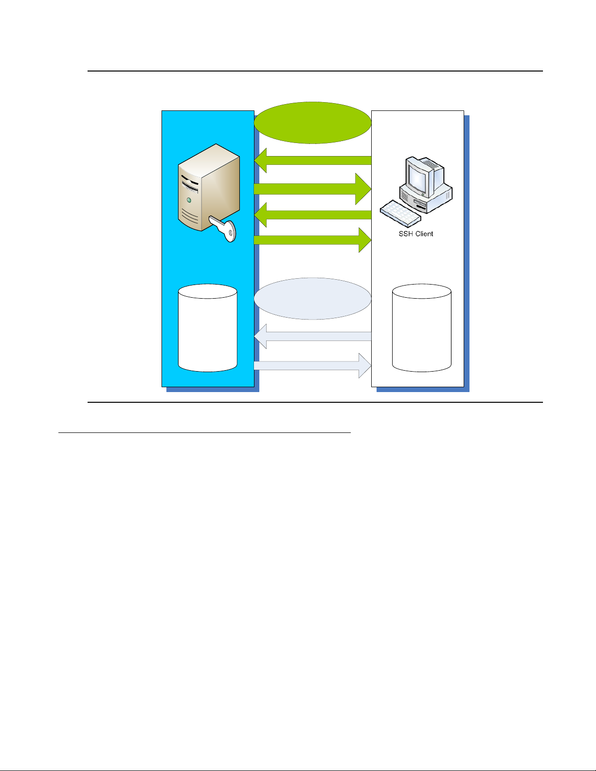
Establishing Switch Access
Figure 21: SSH Session Establishment Process
SSH Cli ent Connection
Establish Connection
Public Key and Encryptions List
Private Key and Encryptions List
SSH
Server
Username List
HOST RS A K ey
Acknowledgement (ACK)
User Authentication
User Passwords
Initiate CLI Session
Procedure for Establishing an SSH Connection
Perform the following steps to establish an SSH connection to the C360 for configuration of
Stack or Router parameters. You can open an SSH session to the Stack Master IP address:
1. Use the show ip ssh CLI command to ensure that an SSH key has been generated on
the switch.
Hostnames List
- Use the crypto key generate dsa CLI command to generate a key if necessary.
2. Enable SSH on the switch using the ip ssh enable CLI command.
3. Connect your station to the network.
4. Verify that you can communicate with the C360 using Ping to the IP of the C360. If there is
no response using Ping, check the IP address and default gateway of both the C360 and
the station.
- The C360 default IP address is 149.49.32.134 and the default subnet mask is
255.255.255.0.
68 Installation and Configuration Guide Avaya C360 Multilayer Stackable Switches, version 4.5
Page 69

5. Using your SSH client software, open a session to the Stack Master IP address.
6. When you are prompted for a password, enter the User Level password root in lower case
letters (do not use uppercase letters).
- The User level prompt will appear when you have established communications with the
C360. You can now configure the C360 stack and change its default IP address.
SSH Commands
The following SSH commands are accessible from Supervisor level.
Table 15: SSH CLI Commands
In order to... Use the following command...
Establishing an SSH Connection
Enable SSH and configure SSH
parameters
Disable the SSH server no ip ssh
Display active SSH sessions on
the device. This command is
only available from the master
module switch context and from
all router contexts.
Disconnect an existing SSH
session. If an SSH session was
entered from the router, it can
only be disconnected from
router mode.
Generate an SSH host key pair crypto key generate dsa
ip ssh enable
show ip ssh
disconnect ssh
Issue 1 July 2006 69
Page 70

Establishing Switch Access
Establishing Access to Other Entities in the Stack (C360 Sessions)
You can use sessions to switch between the CLI of C360 switches, other stack entities, or to
switch between Layer 2 and Layer 3 commands.
To switch between stack entities use the session [<mod_num>] <mode> CLI command.
● <mod_num> is the number of the switch in the stack, counting from the bottom.
● <mode> can be switch, router, wan, or mgp.
Use switch mode to configure layer 2 commands.
Use router mode to configure routing commands.
Examples:
To configure router parameters in the module that you are currently logged into, type the
following command:
session router
To configure the switch parameters, on switch 6, type the command:
session 6 switch.
Note:
Note: When you use the session CLI command the security level stays the same.
70 Installation and Configuration Guide Avaya C360 Multilayer Stackable Switches, version 4.5
Page 71

Establishing a Modem (PPP) Connection
Establishing a Modem (PPP) Connection
Point-to-Point Protocol (PPP) provides a Layer 2 method for transporting multi-protocol
datagrams over modem links.
Connecting a Modem to the Console Port
Before you can establish a PPP connection with a modem can be established, you need to
configure the following:
● C360 IP address: refer to Assigning C360 IP Stack Address for further information.
● net-mask
● PPP parameters that are compatible with the modem's PPP parameters.
1. Connect a terminal to the console port of the C360 switch as described in Connecting a
Terminal to the C360 Serial port.
2. When you are prompted for a Login Name, enter the default name root.
3. When you are prompted for a password, enter the password root. You are now in
Supervisor Level.
4. At the prompt, type:
set interface ppp <ip_addr> <net-mask>
with an IP address and netmask to be used by the C360 to connect via its PPP interface.
Note:
Note: The PPP interface configured with the set interface ppp command must be
on a different subnet from the stack inband interface.
5. Set the baud rate, ppp authentication, and ppp time out required to match your modem.
These commands are described in the Reference Guide for the Avaya C360 Converged
Stackable Switch, 10-300506.
6. At the prompt, type:
set interface ppp enable
● The CLI responds with the following:
Entering the Modem mode within 60 seconds...
Please check that the proprietary modem cable is plugged into the
console port
7. Use the DB-25 to RJ-45 connector provided in the accessory kit to plug the console cable to
the modem's DB-25 connector. Plug the other end of the cable RJ-45 connector to the
C360 console's RJ-45 port.
8. The C360 enters modem mode.
Issue 1 July 2006 71
Page 72

Establishing Switch Access
9. You can now dial into the switch from a remote station, and open a Telnet session to the
PPP interface IP address.
72 Installation and Configuration Guide Avaya C360 Multilayer Stackable Switches, version 4.5
Page 73

SNMP Support
Introduction to SNMP
SNMP Versions
There are currently three versions of SNMP (Simple Network Management Protocol):
● SNMPv1
● SNMPv2c
● SNMPv3
The C360 supports device access using all three versions of SNMP.
Managers and Agents
SNMP Support
SNMP uses software entities called managers and agents to manage network devices. The
manager monitors and controls all other SNMP-managed devices or network nodes on the
network. There must be at least one SNMP Manager in a managed network. The manager is
installed on a workstation located on the network.
An agent resides in a managed device or network node. The agent receives instructions from
the SNMP Manager, generates reports in response to requests from the SNMP Manager, and
also sends management information back to the SNMP Manager as events occur. Each C360
module has an agent. However, on each C360 stack, one module is selected to be the master
module. The stack is managed via the master module's agent.
There are many SNMP management applications, but all these applications perform the same
basic task. They allow SNMP managers to communicate with agent s to config ure, g et statistics
and information, and receive alerts from network devices. You can use any SNMP-compatible
network management system to monitor and control the C360.
Manager/Agent Communication
There are several ways that the SNMP manager and the agent communicate.
The manager can:
● Retrieve a value - a get action
The SNMP manager requests information from the agent, such as the link status of an
Ethernet port or the number of good packets received on the switch. The agent gets the
value of the requested MIB variable and sends the value back to the manager.
Issue 1 July 2006 73
Page 74

Establishing Switch Access
● Retrieve the value immediately after the variable you name - a get-next action.
The SNMP manager retrieves values from the MIB tree. Using the get-next function, you do
not need to know the exact variable name you are looking for. The SNMP manager takes
the variable you name and then uses a sequential search to find the desired variable.
● Change a setting on the agent - a set action
The SNMP manager requests the agent to change the value of the MIB variable. For
example, you can enable or disable a port.
● An agent can send an unsolicited message to the manager at any time if a significant,
predetermined event takes place on the agent. This message is called a trap.
When a trap condition occurs, the SNMP agent sends an SNMP trap message to the
specified trap receiver or trap host. The SNMP Administrator configures the trap host,
usually the SNMP management station, to perform the action needed when a trap is
detected.
SNMPv1
SNMPv1 uses community strings to limit access rights. Each SNMP device is assigned to a
read community and a read-write community. To communica te with a switch, you must send an
SNMP packet with the relevant community name.
By default, if you communicate with a switch using only the read community, you are assigned
the security name "ReadCommN". This security name is mapped to the "ReadCommG" group
by default. This allows you to view the agent's MIB tree, but cannot change any of the values in
the MIB tree.
If you communicate with a switch using the write community, you are assigned the security
name "WriteCommN". This security name is mapped to the "W riteComm" group by default. This
allows you to view the agent's MIB tree and change any of the values in the MIB tree.
CAUTION: If you delete the ReadCommN or WriteCommN users, the ReadCommG or
In addition, traps are sent to designated trap receivers. Packets with trap information also
contains a trap community string.
SNMPv2c
!
CAUTION:
WriteCommG groups, or the SNMPv1View you may not be able to access the
switch using SNMPv1.
SNMPv2c is very similar to SNMPv1. However, SNMPv2c adds support for the get-bulk action
and supports a different trap format.
74 Installation and Configuration Guide Avaya C360 Multilayer Stackable Switches, version 4.5
Page 75

SNMPv3
SNMPv3 enables the following features over SNMPv1 or v2c:
● User authentication with a username and password. Authentication is performed using
● Communication encryption between the Network Management Station (NMS) and the
● Access control definition for specific MIB items available on the SNMP agent
● Notification of specified network events directed toward specified users
● Definition of roles using access control, each with unique access permissions and
The basic components in SNMPv3 access control are users, groups, and views.
In addition. SNMPv3 uses an SNMP engine ID to identify an SNMP entity. An SNMP engine ID
is assigned to each IP address of each device in the network. Each SNMP engine ID should be
unique in the network.
SNMP Support
md5 or sha-1.
SNMP agent at the application level
authentication/encryption requirements
Users
SNMPv3 uses the User-based Security Model (USM) for security, and the View-based Access
Control Model (VACM) for access control. USM uses the HMAC-MD5-96 and HMAC-SHA-96
protocols for user authentication, and the CBC-DES56 protocol for encryption.
A maximum of 21 users, including local users and remote users getting notifications can be
defined on a stack. If the SNMP engine ID changes, all users other than the default user for the
stack are invalid and must be redefined. The SNMP engine ID can be changed via the CLI. In
addition, a change in the IP address of the stack automatically changes the SNMP engine ID.
SNMPv3 supports three security levels:
● NoAuthNoPriv - This is the lowest level of SNMPv3 security . No authentication is done and
no encryption is performed. This method is maintains the same security level as SNMPv1,
but provides a method for limiting the access rights of a user.
● AuthNoPriv - User authentication is performed based on MD5 or SHA algorithms. The
message is sent with an HMAC that is calculated with the user key. The data part is sent
unencrypted.
● AuthPriv - User authentication is performed based on MD5 or SHA algorithms. 'The
message is sent with HMAC for authentication, and encrypted using DES.
To create an SNMPv3 user account, you must provide the following information:
● UserName - string representing the name of the user.
● Maximum length: 32 characters.
Issue 1 July 2006 75
Page 76

Establishing Switch Access
● Authentication Protocol - The authentication protocol to use. Possible values are: No auth,
HMAC MD5, or HMAC SHA-1.
● Authentication Password - The authentication password is transformed using the
authentication protocol and the SNMP engine ID to create an authentication key.
● Privacy Protocol - The privacy protocol to use. Possible values are: No privacy, DES
privacy.
● Privacy Password - The privacy password is transformed using the privacy protocol and
the SNMP engine ID to create a privacy key.
● GroupName - a string of up to 32 characters representing the name of the group.
● SecurityModel - The security model to use. Possible values are: 1 (SNMPv1), 2
(SNMPv2c), 3 (USM).
Groups
In SNMPv3, each user is mapped to a group. The group maps it s users to defined views. These
views define sets of access rights, including read, write, and trap or inform notifications the
users can send.
The group maps its users to views based on the security model an d level with which th e user is
communicating with the switch. Within a group, the following combinations of security model
and level can be mapped to views:
● SNMPv1 - Only requests using SNMPv1 or higher.
● SNMPv2c - Only requests using SNMPv2 or higher.
● NoAuthNoPriv - An SNMPv3 user using the NoAuthNoPriv security level.
● AuthNoPriv - An SNMPv3 user using the AuthNoPriv security level.
● AuthPriv - An SNMPv3 user using the AuthPriv security level.
If a group with the specific security model and level does not exist, then a user can access a
group with lower security model or level. If an SNMPv3 group with NoAuthNoPriv security level
is not defined, SNMPv3 users with a NoAuthNoPriv security level can access the SNMPv2c
view.
To create an SNMPv3 group, you must provide the following information:
● GroupName - String of up to 32 characters representing the name of the group.
● Security model:
-SNMPv1
-SNMPv2c
-SNMPv3
● Security level (for SNMPv3 only):
- NoAuthNoPriv
76 Installation and Configuration Guide Avaya C360 Multilayer Stackable Switches, version 4.5
Page 77

Views
SNMP Support
- AuthNoPriv
- AuthPriv
● View names:
- Read - Allow read-only access to a specified list of Object IDs (OIDs) in the MIB tree.
- Write - Allow read-write access to a specified list of OIDs in the MIB tree.
- Notify - Allow SNMP notifications from a specified list of OIDs to be sent.
Each view consists of a name and a list of OIDs in the MIB tree. This list can be created using
multiple "snmp-server view" commands to either add OIDs to the list or exclude OIDs from a list
of all of the OIDs in the switch's MIB tree.
You can use wildcards to include or exclude an entire branch of OIDs in the MIB tree, using an
asterisk instead of the specific node.
To create an SNMPv3 view, you must provide the following information:
● ViewName - a string of up to 32 characters representing the name of the view.
● ViewType - Indicates whether the specified OID is included or excluded from the view.
● OIDs - A list of the OIDs accessible using the view.
SNMP Commands
The following SNMP commands are available.
Table 16: SNMP CLI Commands 1 of 3
In order to... Use the following command...
Enable SNMP access to the
device
Disable SNMP access to the
device
Enable SNMPv1 access to the
device
Disable SNMPv1 access to the
device
ip snmp
no ip snmp
snmp-server community
no snmp-server community
1 of 3
Issue 1 July 2006 77
Page 78

Establishing Switch Access
Table 16: SNMP CLI Commands 2 of 3
In order to... Use the following command...
Configure the SNMPv3 engine IDsnmp-server engineID
Return the SNMPv3 engine ID
no snmp-server engineID
to its default value
Create an SNMPv3 user snmp-server user
Remove an SNMPv3 user no snmp-server user
Create an SNMPv3 group snmp-server group
Remove an SNMPv3 group no snmp-server group
Create a view or add or exclude
snmp-server view
OIDs from a view
Delete an SNMPv3 view no snmp-server view
Set a read/write/trap SNMPv1
set snmp community
community name
Display a list of SNMPv3 views show snmp view
Display a table of SNMPv3
show snmp userToGroup
users and the groups with which
they are mapped
Display the SNMPv3 engine ID show snmp engineID
Display a list of SNMPv3 groups show snmp group
Display a list of SNMPv3 users show snmp user
Display a list SNMPv3
show snmp
notification receivers and
SNMPv1 trap receivers
Enable or disable link up/link
set port trap
down notifications and traps
Define SNMPv1 trap receivers
set snmp trap
or configure the SNMPv1 traps
sent by the device
Removes SNMPv1 trap
clear snmp trap
receivers
Enable or disable SNMPv1 traps
for authentication failures
set snmp trap enable/disable
auth
2 of 3
78 Installation and Configuration Guide Avaya C360 Multilayer Stackable Switches, version 4.5
Page 79

Table 16: SNMP CLI Commands 3 of 3
In order to... Use the following command...
SNMP Support
Enable SNMP notifications
(traps and inform)
Disable SNMP notifications
(traps and inform)
Create an SNMPv3 remote user
for SNMP notifications
Remove an SNMPv3 remote
user for SNMP notifications
Configure the SNMPv3 timeout
and retries for notification
Define an SNMPv3 notification
host
Remove an SNMPv3 notification
host
snmp-server enable notifications
no snmp-server notifications
snmp-server remote-user
no snmp-server remote-user
snmp-server informs
snmp-server host
no snmp-server host
3 of 3
Issue 1 July 2006 79
Page 80

Establishing Switch Access
RADIUS
Introduction to RADIUS
User accounts are typically maintained locally on the switch. Therefore, if a site contains
multiple Avaya Switches, it is necessary to configure each switch with its own user accounts.
Additionally, if for example a "read-write" user has to be changed into a "read-only" user, you
must change all the "read-write" passwords configured locally in every switch, in order to
prevent him from accessing this level. This is obviously not effective management. A better
solution is to have all of the user login information kept in a central location where all the
switches can access it. C360 features such a solution: the Remote Authentication Dial-In User
Service (RADIUS).
A RADIUS authentication server is installed on a central computer at the customer's site. On
this server user authentication (account) information is configured that provides various degrees
of access to the switch. The C360 will run as a RADIUS client. When a user attempts to log into
the switch, if there is no local user account for the entered user name and password, then the
switch will send an Authentication Request to the RADIUS server in an attempt to authenticate
the user remotely. If the user name and password are authenticated, then the RADIUS server
responds to the switch with an Authentication Acknowledgement that includes information on
the user's privileges ("administrator", "read-write", or "read-only"), and the user is allowed to
gain access to the switch. If the user is not authenticated, then an Authentication Reject is sent
to the switch and the user is not allowed access to the switch's embedded management.
The Remote Authentication Dial-In User Service (RADIUS) is an IETF standard (RFC 2138)
client/server security protocol. Security and login information is stored in a central location
known as the RADIUS server. RADIUS clients, such as the C360, communicate with the
RADIUS server to authenticate users.
All transactions between the RADIUS client and server are authenticated through the use of a
"shared secret" which is not sent over the network. The shared secret is an authentication
password configured on both the RADIUS client and its RADIUS servers. The shared secret is
stored as clear text in the client's file on the RADIUS server, and in the non-volatile memory of
the C360. In addition, user passwords sent between the client and server are encrypted for
increased security.
In the C360, RADIUS is used to authenticate management stations and (independently) for
802.1x port-based access control.
Figure 22
illustrates the RADIUS authentication procedure:
80 Installation and Configuration Guide Avaya C360 Multilayer Stackable Switches, version 4.5
Page 81
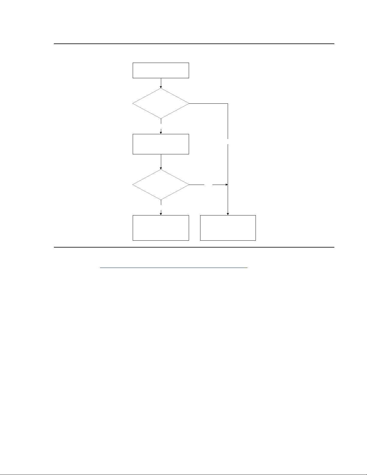
Figure 22: RADIUS Authentication Procedure
User attempts login
Local User
account authenticated
in switch?
No
RADIUS
Authentication
request sent to
RADIUS Server
User name and
password
authenticated?
No
Authentication Reject
sent to switch
User cannot access
switch embedded
management
Yes
Perform log-in according
to user's privilege level
Yes
to switch
RADIUS is also part of IEEE 802.1x port-based network access control. For information on
802.1x, refer to IEEE 802.1x (Port Based Network Access Control)
.
Issue 1 July 2006 81
Page 82

Establishing Switch Access
RADIUS Commands
The following RADIUS commands are accessible from Supervisor level.
Table 17: RADIUS CLI Commands
In order to... Use the following command...
Enable or disable authentication
for the C360 switch. RADIUS
authentication is disabled by
default
Set a primary or secondary
RADIUS server IP address
Configure a character string to
be used as a "shared secret"
between the switch and the
RADIUS server
Set the RFC 2138 approved
UDP port number.
Set the number of times an
access request is sent when
there is no response
Set the time to wait before
re-sending an access request
Remove a primary or secondary
RADIUS authentication server
Display all RADIUS
authentication configurations.
Shared secrets are not
displayed.
set radius authentication
set radius authentication server
set radius authentication secret
set radius authentication
udp-port
set radius authentication
retry-number
set radius authentication
retry-time
clear radius authentication
server
show radius authentication
For a complete description of the RADIUS CLI commands, including syntax and output
examples, refer to the Reference Guide for the Avaya C360 Converged Stackable Switch,
10-300506.
82 Installation and Configuration Guide Avaya C360 Multilayer Stackable Switches, version 4.5
Page 83

Recovery Password
Introduction to Recovery Password
The C360 provides a recovery password in the event that you have forgotten the login
password for the switch. The recovery password feature enables you to login to the device in a
super user mode and change the regular login password.
The recovery password feature can be disabled preventing unauthorized user to login to the
device using the recovery password. However, if the recovery password feature is disables and
you forget the login password, it will not be possible to log in to the switch. By default the
recovery password feature is enabled.
To use the recovery password feature, you must connect to the switch's console port. Log in
using the user name "root" and password "ggdaseuaimhrke". Use the set username command
to change the password for the user "root".
Recovery Password
Tip:
Tip: Enabling and disabling the Recovery Password protocol can only be done using
a direct console connection via the Console port.
Recovery Password CLI Commands
The following recovery password commands are available.
Table 18: Recovery Password CLI Commands
In order to... Use the following command...
Enable the recovery password
feature on the switch
Disable the recovery password
feature on the switch
For a complete description of the recovery password commands, including syntax, refer to
Reference Guide for the Avaya C360 Converged Stackable Switch, 10-300506.
terminal recovery password
enable
no terminal recovery password
Issue 1 July 2006 83
Page 84

Establishing Switch Access
Allowed Managers
Allowed Managers Introduction
With the Allowed Managers feature, the network manager can determine who may or may not
gain management access to the switch. The feature can be enabled or disabled (default is
disabled). When enabled, only those stations that are configured in the Allowed Managers t able
are able to gain Telnet, HTTP, and SNMP management access to the switch.
You can configure up to 20 Allowed Managers by adding or removing their IP address from the
Allowed Managers List.
Tip:
Tip: The identification of an "Allowed Manager" is done by checking the Source
IP address of the packets. Thus, if the Source IP address is modified on the way
(NAT, Proxy, etc.), even an "Allowed Manager" will not be able to access the
C360.
Allowed Managers CLI Commands
The following Allowed Managers commands are available.
Table 19: Allowed Managers CLI Commands 1 of 2
In order to... Use the following command...
When set to enabled - only
managers with IP address
specified in the allowed table will
be able to access the device
Add/delete IP address of
manager to/from the allowed
table
Show the IP addresses of the
managers that are allowed to
access the device
set allowed managers
set allowed managers ip
show allowed managers table
1 of 2
84 Installation and Configuration Guide Avaya C360 Multilayer Stackable Switches, version 4.5
Page 85

Table 19: Allowed Managers CLI Commands 2 of 2
In order to... Use the following command...
Allowed Managers
Show whether the status of
allowed managers is enabled or
disabled
Show the IP addresses of the
managers that are currently
connected
show allowed managers status
show secure current
2 of 2
Issue 1 July 2006 85
Page 86

Establishing Switch Access
Allowed Protocols
Allowed Protocols Introduction
With the Allowed Protocols feature, the network manager can determine the IP protocols
enabled on the switch. This feature can be used to block access to the switch using specific IP
protocols. Each protocol can be independently enabled or disabled on the switch.
Tip:
Tip: Enabling and disabling the Recovery Password protocol can only be done using
a direct console connection via the Console port.
Allowed Protocols CLI Commands
The following Allowed Protocols commands are available.
Table 20: Allowed Protocol CLI Commands 1 of 2
In order to... Use the following command...
Enable Telnet on the switch ip telnet enable
Disable Telnet on the switch no ip telnet
Enable HTTP on the switch ip http enable
Disable HTTP on the switch no ip http
Enable the switch agent to
accept ICMP redirect packets
sent to it
Enable the switch agent to
ignore ICMP redirect packets
sent to it
Enable SNMP on the switch snmp-server
Disable SNMP on the switch no snmp-server
Enable SNMPv1 switch access snmp-server community
ip icmp redirect
no icmp redirect
Disable SNMPv1 switch access no snmp-server community
1 of 2
86 Installation and Configuration Guide Avaya C360 Multilayer Stackable Switches, version 4.5
Page 87

Table 20: Allowed Protocol CLI Commands 2 of 2
In order to... Use the following command...
Enable SSH on the switch ip ssh enable
Disable SSH on the switch no ip ssh
Allowed Protocols
Enable Recovery Password on
the switch
Disable Recovery Password on
the switch
Enable Telnet access from the
switch
Disable Telnet access from the
switch
terminal recovery password
enable
no terminal recovery password
ip telnet-client enable
no ip telnet-client
2 of 2
Issue 1 July 2006 87
Page 88

Establishing Switch Access
88 Installation and Configuration Guide Avaya C360 Multilayer Stackable Switches, version 4.5
Page 89

Section 3: Avaya C360 Configuration
Issue 1 July 2006 89
Page 90

90 Installation and Configuration Guide Avaya C360 Multilayer Stackable Switches, version 4.5
Page 91

Chapter 6: Avaya C360 Default Settings
This section describes the procedures for the first-time configuration of the C360. The factory
defaults are set out in detail in the tables included in this chapter.
Configuring the Switch
You may configure the C360 using the text-based Command Line Interface (CLI), the built-in
C360 Device Manager or Avaya Integrated Management.
For instructions on the CLI, see the Reference Guide for the Avaya C360 Converged Stackable
Switch, 10-300506.
For instructions on the use of the graphical user interfaces, refer to the C360 Device Manager
User Guide on the Avaya C360 Documentation and Utilities CD.
C360 Default Settings
The default settings for the C360 switch and its ports are determined by the C360 firmware.
These default settings are subject to change in newer versions of the C360 firmware. See the
C360 Release Notes for the most up-to-date settings.
Table 21: Default Switch Settings 1 of 2
Function Default Setting
IP address 149.49.32.134
Subnet Mask 255.255.255.0
Default gateway 0.0.0.0
Management VLAN ID 1
Spanning tree Enabled
Bridge priority for Spanning Tree 32768
Spanning tree version Common spanning
tree
1 of 2
Issue 1 July 2006 91
Page 92

Avaya C360 Default Settings
Table 21: Default Switch Settings 2 of 2
Function Default Setting
MAC aging Enabled
MAC aging time 5 minutes
Keep alive frame transmission Enabled
Network time acquisition Enabled, Time
protocol
IP multicast filtering Disabled
802.1x system-auth-control Disabled
802.1x port-control Auto
RADIUS server Disabled
Time server IP address 0.0.0.0
Timezone offset 0 hours
SNMPv1 communities:
Read-only
Read-write
Trap SNMP
Public
Public
Public
SNMP authentication trap Disabled
CLI timeout 15 Minutes
System logging Disabled
Allowed protocols:
SNMP
Telnet
HTTP
Telnet
ICMP redirect
SSH
Telnet client
Recovery password
Enabled
Enabled
Enabled
Enabled
Enabled
Disabled
Disabled
Enabled
User Name/Password root/root
2 of 2
92 Installation and Configuration Guide Avaya C360 Multilayer Stackable Switches, version 4.5
Page 93

Configuring the Switch
Tip:
Tip: Functions operate in their default settings unless configured otherwise.
Table 22: Default Port Settings
Function Default Setting
Ports 1 to 24
Ports 51 and 52
or 1 to 48
Duplex mode Half/Full
Full duplex only
duplex
depending on
auto-negotiati
on results
Port speed 10/100 Mbps
1000 Mbps
Depending on
autonegotiation
results
Auto-negotiation
Flow control Disabled (no
Flow control
auto-negotiation
1
Enable Enable
Disabled (no
pause)
pause)
Not applicable Disabled (no
pause)
advertisement
Administrative state Enable Enable
Port VLAN ID 1 1
Eavesdropping
Prevention
Intrusion Prevention
Tagging mode Clear Clear
Port priority 0 0
Spanning Tree cost 19 4
Spanning Tree port
128 128
priority
1. Ensure that the other side is also set to Autonegotiation
Enabled.
Issue 1 July 2006 93
Page 94

Avaya C360 Default Settings
94 Installation and Configuration Guide Avaya C360 Multilayer Stackable Switches, version 4.5
Page 95

Chapter 7: Switch Configuration
Introduction
This chapter describes the parameters you can define, such as its name and location, time
parameters, and so on. In addition, this chapter describes methods for saving and deploying
device configurations and monitoring CPU utilization.
This chapter contains the following sections:
● Basic Switch Configuration
● Uploading and Downloading Device Configurations and Images
● SCP Protocol Support
● System Logging
● Telnet Client Support
● Monitoring CPU Utilization
Basic Switch Configuration
Use the CLI commands briefly described below for configuring the display on your terminal or
workstation.The rules of syntax and output examples are all set out in detail in the Reference
Guide for the Avaya C360 Converged Stackable Switch, 10-300506.
Table 23: Basic Switch Configuration CLI Commands 1 of 2
In order to... Use the following command...
Open a CLI session to an entity
in the stack
Display or set the terminal width
(in characters)
Display or set the terminal
length (in lines)
Display or set the prompt hostname
session
terminal width
terminal length
1 of 2
Issue 1 July 2006 95
Page 96

Switch Configuration
Table 23: Basic Switch Configuration CLI Commands 2 of 2
In order to... Use the following command...
Return the prompt to its default
value
Clear the current terminal
display
Set the number of minutes
before an inactive CLI session
automatically logs out
Display the number of minutes
before an inactive CLI session
automatically times out
Access Layer 3 configuration if
not logged in as supervisor (see
Entering the Supervisor
Level on page 61)
System Parameter Configuration
no hostname
clear screen
set logout
show logout
configure
2 of 2
Identifying the system
In order to make a C360 switch easier to identify, you can define a name for the switch, contact
information for the switch technician, and the location of the switch in the organization. The
rules of syntax and output examples are all set out in detail in the Reference Guide for the
Avaya C360 Converged Stackable Switch, 10-300506.
Table 24: System Identification CLI Commands
In order to... Use the following command...
Configure the system name. set system name
Configure the system contact
person
Configure the system location set system location
set system contact
96 Installation and Configuration Guide Avaya C360 Multilayer Stackable Switches, version 4.5
Page 97

Operating parameters
You can use the following commands to configure and display the mode of operation for the
switch and display key parameters. The rules of syntax and output examples are all set out in
detail in the Reference Guide for the Avaya C360 Converged Stackable Switch, 10-300506.
Table 25: Operating Parameter CLI Commands
In order to... Use the following command...
Basic Switch Configuration
Configure the basic mode of
operation of a module to either
Layer 2 or Router
Display the mode of operation show device-mode
Display system parameters show system
Display module information for
all modules within the stack
set device-mode
show module
Network Time Acquiring Protocols Parameter Configuration
The C360 can acquire the time from a Network Time Server. C360 supports the SNTP Protocol
(RFC 958) over UDP port 123 or TIME protocol over UDP port 37. Use the CLI commands
briefly described below for configuring and display time information and acquiring parameters.
The rules of syntax and output examples are all set out in detail in the Reference Guide for the
Avaya C360 Converged Stackable Switch, 10-300506.
In order to... Use the following command...
Restore the time zone to its
default, UTC.
clear timezone
Configure the time zone for the
system
Configure the time protocol for
use in the system
Enable or disable the time client set time client
Configure the network time
server IP address
Display the current time show time
set timezone
set time protocol
set time server
1 of 2
Issue 1 July 2006 97
Page 98

Switch Configuration
In order to... Use the following command...
Display the time status and
parameters
Display the current time zone
offset
Get the time from the time
server
show time parameters
show timezone
get time
2 of 2
98 Installation and Configuration Guide Avaya C360 Multilayer Stackable Switches, version 4.5
Page 99

Uploading and Downloading Device Configurations and Images
Uploading and Downloading Device Configurations and
Images
The C360 allows you to backup and restore device configurations and configure multiple
devices using Simple Network Management Protocol (SNMP) and Trivial File Transfer Protocol
(TFTP) or Secure Copy Protocol (SCP) to exchange information with the devices. For more
information on SNMP, refer to SNMP Support
to SCP Protocol Support
on page 103.
When you make changes to a switch’s configuration, you may find that the overall effect of the
configuration change may have a negative effect on the performance of the device in your
network. By uploading a switch’s configuration file before any configuration changes, you can
easily restore the switch to a previous configuration.
In addition, you can download the same configuration file to multiple devices in the network,
resulting in a consistent configuration.
You can also download image files to the switch. The image files provide the switch’s firmware
and device manager.
on page 73. For more information on SCP, refer
Tip:
Tip: Only parameters that differ from the factory default settings for the switch are
included in the configuration file. Therefore, it is important to re-initialize the
NVRAM to the factory default settings before downloading configuration files to
the switch.
The C360 commands for uploading and downloading device configuration files differ for the
Layer 2 and Layer 3 configuration files.
Tip:
Tip: To upload or download files, you must log in to the device as a user with
Supervisor level privileges.
Table 26: Configuration Files and Their Contents
File name Contents
module-config Layer 2 switch-level configuration, e.g., port
parameters, VLAN binding, LAGs
stack-config Layer 2 stack-level configuration, e.g. global
parameters, Spanning Tree, VLANs
running-config Layer 3 configuration currently running
(switch-level)
*
startup-config Layer 3 configuration used when switch is reset
(switch-level)
Issue 1 July 2006 99
Page 100

Switch Configuration
Note:
Note: *The running configuration is not saved automatically after a reset. If you wish to
make the currently running configuration the startup configuration, use the copy
running-config startup-config command before preforming a reset.
Layer 2 Configuration File
The Layer 2 configuration file contains the full Layer 2 configuration of the switch in the format of
the CLI commands necessary to configure the device to its current configuration. You can edit
the file in a text editor, however, it is recommended that you perform the configuration changes
using the C360 Device Manager and/or the CLI. To upload or download Layer 2 configuration
files, you must be in a switch mode.
Use the CLI commands described below for uploading and downloading Layer 2 configuration
files. The rules of syntax and output examples are all set out in det ail in the Reference Guide for
the Avaya C360 Converged Stackable Switch, 10-300506.
In order to... Use the following command...
Download a module
configuration file to the device
using SCP
Download a stack configuration
file to the device using SCP
Download a module
configuration file to the device
using TFTP
Download a stack configuration
file to the device using TFTP
Upload a module configuration
file from the device using SCP
Upload a stack configuration file
from the device using SCP
Upload a module configuration
file from the device using TFTP
Upload a stack configuration file
from the device using TFTP
copy scp module-config
copy scp stack-config
copy tftp module-config
copy tftp stack-config
copy module-config scp
copy stack-config scp
copy module-config tftp
copy stack-config tftp
1 of 2
100 Installation and Configuration Guide Avaya C360 Multilayer Stackable Switches, version 4.5
 Loading...