

Page 1

Configuring Bridging Services
Router Software Version 10.0
Site Manager Software Version 4.0
Part No. 112950 Rev. A
January 1996
Page 2

4401 Great America Parkway 8 Federal Street
Santa Clara, CA 95054 Billerica, MA 01821
Copyright © 1988–1996 Bay Networks, Inc.
All rights reserved. Printed in the USA. January 1996.
The information in this document is subject to change without notice. The statements, configurations, technical data, and
recommendations in this document are believed to be accurate and reliable, but are presented without express or implied
warranty. Users must take full responsibility for their applications of any products specified in this document. The
information in this document is proprietary to Bay Networks, Inc.
The software described in this document is furnished under a license agreement and may only be used in accordance with the
terms of that license. A summary of the Software License is included in this document.
Restricted Rights Legend
Use, duplication, or disclosure by the United States Government is subject to restrictions as set forth in subparagraph
(c)(1)(ii) of the Rights in Technical Data and Computer Software clause at DFARS 252.227-7013.
Notice for All Other Executive Agencies
Notwithstanding any other license agreement that may pertain to, or accompany the delivery of, this computer software, the
rights of the United States Government regarding its use, reproduction, and disclosure are as set forth in the Commercial
Computer Software-Restricted Rights clause at FAR 52.227-19.
Trademarks of Bay Networks, Inc.
ACE, AFN, BCN, BLN, BN, CN, FRE, LN, Optivity, SynOptics, SynOptics Communications, Wellfleet and the Wellfleet
logo are registered trademarks and AN, ANH, ASN, BaySIS, BayStack, BCNX, BLNX, BNX, EZ Internetwork, EZ LAN,
FN, PathMan, PhonePlus, PPX, Quick2Config, RouterMan, SPEX, Bay Networks, Bay Networks Press, the Bay Networks
logo and the SynOptics logo are trademarks of Bay Networks, Inc.
Third-Party T rademarks
All other trademarks and registered trademarks are the property of their respective owners.
Statement of Conditions
In the interest of improving internal design, operational function, and/or reliability, Bay Networks, Inc. reserves the right to
make changes to the products described in this document without notice.
Bay Networks, Inc. does not assume any liability that may occur due to the use or application of the product(s) or circuit
layout(s) described herein.
Portions of the code in this software product are Copyright © 1988, Regents of the University of California. All rights
reserved. Redistribution and use in source and binary forms of such portions are permitted, provided that the above copyright
notice and this paragraph are duplicated in all such forms and that any documentation, advertising materials, and other
materials related to such distribution and use acknowledge that such portions of the software were developed by the
University of California, Berkeley. The name of the University may not be used to endorse or promote products deri ved from
such portions of the software without specific prior written permission.
SUCH PORTIONS OF THE SOFTWARE ARE PROVIDED “AS IS” AND WITHOUT ANY EXPRESS OR IMPLIED
WARRANTIES, INCLUDING, WITHOUT LIMITATION, THE IMPLIED WARRANTIES OF MERCHANTABILITY
AND FITNESS FOR A PARTICULAR PURPOSE.
In addition, the program and information contained herein are licensed only pursuant to a license agreement that contains
restrictions on use and disclosure (that may incorporate by reference certain limitations and notices imposed by third parties).
Page 3

Bay Networks Software License
Note:
This is Bay Networks basic license document. In the absence of a
software license agreement specifying varying terms, this license — or the
license included with the particular product — shall govern licensee’s use of
Bay Networks software.
This Software License shall govern the licensing of all software provided to licensee by Bay Networks (“Software”).
Bay Networks will provide licensee with Software in machine-readable form and related documentation
(“Documentation”). The Software provided under this license is proprietary to Bay Networks and to third parties from
whom Bay Networks has acquired license rights. Bay Networks will not grant any Software license whatsoev er , either
explicitly or implicitly, except by acceptance of an order for either Software or for a Bay Networks product
(“Equipment”) that is packaged with Software. Each such license is subject to the following restrictions:
1. Upon delivery of the Software, Bay Networks grants to licensee a personal, nontransferable, none xclusiv e license
to use the Software with the Equipment with which or for which it was originally acquired, including use at any
of licensee’s facilities to which the Equipment may be transferred, for the useful life of the Equipment unless
earlier terminated by default or cancellation. Use of the Software shall be limited to such Equipment and to such
facility. Software which is licensed for use on hardware not offered by Bay Networks is not subject to restricted
use on any Equipment, however, unless otherwise specified on the Documentation, each licensed copy of such
Software may only be installed on one hardware item at any time.
2. Licensee may use the Software with backup Equipment only if the Equipment with which or for which it was
acquired is inoperative.
3. Licensee may make a single copy of the Software (but not firmware) for safekeeping (archives) or backup
purposes.
4. Licensee may modify Software (but not firmware), or combine it with other software, subject to the provision
that those portions of the resulting software which incorporate Software are subject to the restrictions of this
license. Licensee shall not make the resulting software available for use by any third party.
5. Neither title nor ownership to Software passes to licensee.
6. Licensee shall not provide, or otherwise make available, any Software, in whole or in part, in any form, to any
third party. Third parties do not include consultants, subcontractors, or agents of licensee who have licensee’s
permission to use the Software at licensee’s facility, and who have agreed in writing to use the Software only in
accordance with the restrictions of this license.
7. Third-party owners from whom Bay Networks has acquired license rights to software that is incorporated into
Bay Networks products shall have the right to enforce the provisions of this license against licensee.
8. Licensee shall not remove or obscure any copyright, patent, trademark, trade secret, or similar intellectual
property or restricted rights notice within or affixed to any Software and shall reproduce and affix such notice on
any backup copy of Software or copies of software resulting from modification or combination performed by
licensee as permitted by this license.
4401 Great America Parkway, Santa Clara, CA 95054
8 Federal Street, Billerica, MA 01821
Bay Networks, Inc.
Page 4

Bay Networks Software License
9. Licensee shall not reverse assemble, reverse compile, or in any way reverse engineer the Software. [Note: For
licensees in the European Community, the Softw are Directiv e dated 14 May 1991 (as may be amended from time
to time) shall apply for interoperability purposes. Licensee must notify Bay Networks in writing of any such
intended examination of the Software and Bay Networks may provide review and assistance.]
10. Notwithstanding any foregoing terms to the contrary, if licensee licenses the Bay Networks product “Site
Manager,” licensee may duplicate and install the Site Manager product as specified in the Documentation. This
right is granted solely as necessary for use of Site Manager on hardware installed with licensee’s network.
11. This license will automatically terminate upon improper handling of Software, such as by disclosure, or Bay
Networks may terminate this license by written notice to licensee if licensee fails to comply with any of the
material provisions of this license and fails to cure such failure within thirty (30) days after the receipt of written
notice from Bay Networks. Upon termination of this license, licensee shall discontinue all use of the Software
and return the Software and Documentation, including all copies, to Bay Networks.
12. Licensee’s obligations under this license shall survive expiration or termination of this license.
(continued)
4401 Great America Parkway, Santa Clara, CA 95054
8 Federal Street, Billerica, MA 01821
Bay Networks, Inc.
Page 5

About This Guide
If you are responsible for configuring and managing Bay Networks routers, you
should read this guide to learn how to customize Bay Networks router software
for bridging services.
This guide,
• Transparent bridging services (Chapter 1)
• Source routing bridge services (Chapter 2)
• NetBIOS services (Chapter 3)
• Translation bridge services (Chapter 4)
• Native mode LAN (NML) services (Chapter 5)
Audience
Written for system and network managers, this guide presents information on how
to configure the Bay Networks implementation of bridging interfaces to suit your
environment.
Before Y ou Begin
Before using this guide, you must complete the following procedures:
• Create and save a configuration file that has at least one bridging interface.
• Retrieve the configuration file in local, remote, or dynamic mode.
Configuring Bridging Services
, offers details on configuring
• Reboot the router with the configuration file.
Refer to
Configuring Routers
for instructions.
xvii
Page 6

Configuring Bridging Services
Bay Networks Customer Support
Bay Networks provides live telephone technical support to our distributors,
resellers, and service-contracted customers from two U.S. and three international
support centers. If you have purchased your Bay Networks product from a
distributor or authorized reseller, contact the technical support staff of that
distributor or reseller for assistance with installation, configuration,
troubleshooting, or integration issues.
Customers also have the option of purchasing direct support from Bay Networks
through a variety of service programs. The programs include priority access
telephone support, on-site engineering assistance, software subscription, hardware
replacement, and other programs designed to protect your investment.
To purchase any of these support programs, including PhonePlus™ for 24-hour
telephone technical support, call 1-800-2LANWAN. Outside the U.S. and
Canada, call (408) 764-1000. You can also receive information on support
programs from your local Bay Networks field sales office, or purchase Bay
Networks support directly from your reseller. Bay Networks provides several
methods of receiving support and information on a nonpriority basis through the
following automated systems.
CompuServe
xviii
Bay Networks maintains an active forum on CompuServ e. All you need to join us
online is a computer, a modem, and a CompuServe account. We also recommend
using the CompuServe Information Manager software, available from
CompuServe.
The Bay Networks forum contains libraries of technical and product documents
designed to help you manage and troubleshoot your Bay Networks products.
Software agents and patches are available, and the message boards are monitored
by technical staff and can be a source for problem solving and shared experiences.
Customers and resellers holding Bay Networks service contracts can visit the
special libraries to acquire advanced levels of support documentation and
software.
To open an account and receive a local dial-up number, call CompuServe at
1-800-524-3388 and ask for Representative No. 591.
• In the United Kingdom, call Freephone 0800-289378.
Page 7

• In Germany, call 0130-37-32.
• In Europe (except for the United Kingdom and Germany), call
• Outside the U.S., Canada, and Europe, call (614) 529-1349 and ask for
Once you are online, you can reach our forum by typing the command GO
BAYNETWORKS at any ! prompt.
InfoFACTS
InfoFACTS is the Bay Networks free 24-hour fax-on-demand service. This
automated system contains libraries of technical and product documents designed
to help you manage and troubleshoot your Bay Networks products. The system
can return a fax copy to the caller or to a third party within minutes of being
accessed.
W orld Wide Web
The World Wide Web (WWW) is a global information system for file distribution
and online document viewing via the Internet. You need a direct connection to the
Internet and a Web Browser (such as Mosaic or Netscape).
About This Guide
(44) 272-760681.
Representative No. 591, or consult your listings for an office near you.
Bay Networks maintains a WWW Home Page that you can access at http://
www.baynetworks.com. One of the menu items on the Home Page is the
Customer Support Web Server, which offers technical documents, software
agents, and an E-mail capability for communicating with our technical support
engineers.
How to Get Help
For additional information or advice, contact the Bay Networks Technical
Response Center in your area:
United States 1-800-2LAN-WAN
Valbonne, France (33) 92-966-968
Sydney, Australia (61) 2-903-5800
Tokyo, Japan (81) 3-328-005
xix
Page 8

Configuring Bridging Services
.
Conventions
This section describes the conventions used in this guide.
angle brackets (< >) Indicate that you choose the text to enter based on the
arrow character (➔) Separates menu and option names in instructions.
description inside the brackets. Do not type the
brackets when entering the command. Example: if
command syntax is
192.32.10.12
Example: Protocols
<ip_address>
➔
AppleTalk identifies the
, you enter
ping
AppleTalk option in the Protocols menu.
ping
bold text
Indicates text that you need to enter and command
dinfo
names in text. Example: Use the
command.
brackets ([ ]) Indicate optional elements. You can choose none, one,
or all of the options.
italic text
Indicates variable values in command syntax
descriptions, new terms, file and directory names, and
book titles.
quotation marks (“ ”) Indicate the title of a chapter or section within a book.
screen text
ellipsis points Horizontal (. . .) and vertical ellipsis points indicate
Indicates data that appears on the screen. Example:
Bay Networks Trap Monitor Filters
.
()
.
Set
omitted information.
vertical line (|) Indicates that you enter only one of the parts of the
command. The vertical line separates choices. Do not
type the vertical line when entering the command.
Example: If the command syntax is
show at routes
show at routes
nets
|
, you enter either
show at nets
or
, but not both.
xx
Page 9

Ordering Bay Networks Publications
To purchase additional copies of this document or other Bay Networks
publications, order by part number from Bay Networks Press™ at the following
numbers. You may also request a free catalog of Bay Networks Press product
publications.
Phone: 1-800-845-9523
FAX - U.S./Canada: 1-800-582-8000
FAX - International: 1-916-939-1010
Acronyms
APE all-paths explorer frame
ARE all-routes explorer frame
ARP Address Resolution Protocol
BPDU Bridge Protocol Data Unit
CUGID closed user group ID
DA destination address
DLCI data link connection identifier
DLSw data link switching
DSAP destination service access point
FCS frame check sequence
FDDI Fiber Distributed Data Interface
IEEE Institute of Electrical and Electronic Engineers
IP Internet Protocol
IPX Internet Packet Exchange
LLC logical link control
LNM LAN Network Manager
MAC media access control
MIB Management Information Base
MTU Maximum Transmission Unit
NetBIOS Network Basic Input/Output System
NML Native Mode LAN
OUI organizationally unique identifier
About This Guide
xxi
Page 10

Configuring Bridging Services
PPP Point-to-Point Protocol
RFC Request for Comments
RIF Routing Information Field
SA source address
SAP service access point
SMDS Switched Multimegabit Data Services
SNAP Subnetwork Access Protocol
SR source routing
SRF specifically routed frame
SSAP session service access point
STE spanning tree explorer frame
TB transparent bridging
XNS Xerox Network System
xxii
Page 11

Using Transparent Bridge Services
This chapter contains information on the following topics:
• The transparent bridge, including an overview of the transparent bridge and
details on how the spanning tree algorithm works
• Enabling bridge service and spanning tree on an interface
• Transparent bridge parameters, including information on how to edit the
parameters using Configuration Manager.
• Deleting the bridge and spanning tree from the router
Transparent Bridge Overview
Chapter 1
Transparent bridges are data-link layer relay devices that connect two or more
networks. They use media access control (MA C) source and destination addresses
to relay frames between connected networks.
Note:
We use the terms
throughout this chapter.
The transparent bridge provides three primary services:
• Learns the addresses of endstations on connected networks
• Forwards or drops frames based on knowledge it acquires about endstation
addresses or user-configured filters
• Ensures a loop-free topology throughout the extended network, using the
spanning tree algorithm
bridge
and
transparent bridge
interchangeably
1-1
Page 12

Configuring Bridging Services
A transparent bridge also provides some translation services, converting frames
for bridging between Ethernet/802.3 LANs and Fiber Distributed Data Interface
(FDDI) LANs. Refer to “The Translation Process” later in this chapter for details
on translation services.
How the Bridge Works
The bridge receives and examines every frame transmitted on the networks to
which it is attached. It learns endstation addresses by reading the source address
of the endstation that transmitted the frame and noting which LAN interface
received the frame. The bridge enters this information into a data structure called
forwarding table
the
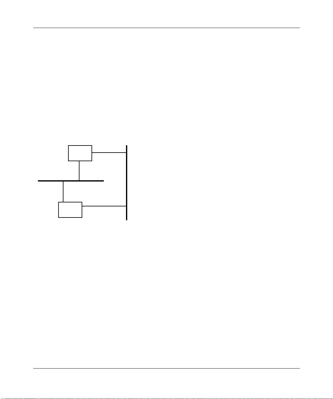
For example, in Figure 1-1, if Node 2 transmits a frame onto the network for the
first time, the bridge receives the frame and makes an update to its forwarding
table. The bridge notes that Node 2 is in the direction of LAN A.
, which the bridge constantly updates.
Forwarding Table
Node MAC Addr LAN
1-2
00:00:A2:00:00:01
00:00:A2:00:00:02
00:00:A2:00:00:03
00:00:A2:00:00:04
LAN A
Bridge
Node 1
MAC Address=
00:00:A2:00:00:01
Node 2
MAC Address=
00:00:A2:00:00:02 00:00:A2:00:00:03
Figure 1-1. Forwarding Table Update
A
A
B
B
MAC Address=
Update
Node 3
LAN B
Node 4
MAC Address=
00:00:A2:00:00:04
Page 13

Using Transparent Bridge Services
The bridge then forwards (relays to another network) or drops (discards) the frame
based on the forwarding table entries. When the bridge receives a frame, it
compares the frame’s destination address with addresses in the forwarding table.
One of these situations results:
• If the frame’s destination address is on the same LAN as its source address,
the bridge discards the frame; all nodes on that LAN already received this
frame.
• If the frame’s destination address is on a different LAN than its source
address, the bridge
forwards
the frame to that LAN.
• If there is no match for the frame’s destination address in the forwarding
table, the bridge forwards the frame to all networks except the one that
received the frame. This is called flooding.
• If the frame is destined for the bridge (for example, a spanning tree frame),
the bridge forwards the frame to the appropriate bridge entity and processes it
internally .
Note:
If a frame is forwarded or flooded to a LAN using a different data-link
level protocol, the bridge translates the frame to the appr opriate frame format
before transmission.
The T ranslation Process
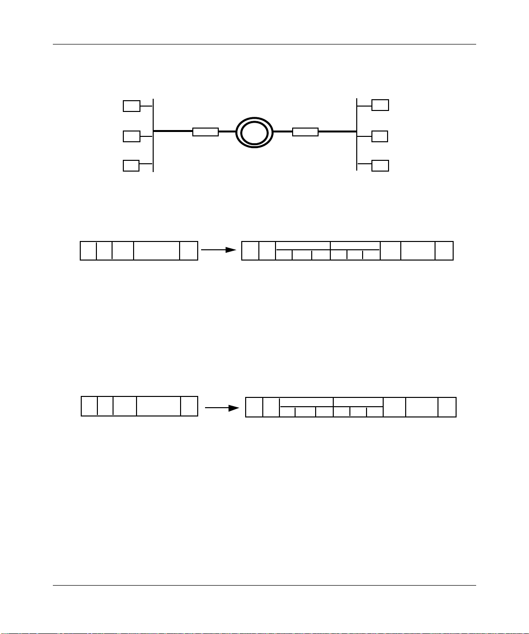
The transparent bridge translates frames for bridging between Ethernet/802.3
LANs and FDDI LANs. When the transparent bridge receives Ethernet/802.3
frames destined for an FDDI LAN, it reformats those frames to the FDDI MAC
frame format. The transparent bridge sets the original MAC frame type in the
logical link control (LLC) header. Therefore, if the frame passes through a second,
FDDI-to-Ethernet/802.3 bridge, that bridge can translate the frame back to its
original format.
The bridge translates all Ethernet MAC frames to FDDI MAC and IEEE 802.2
LLC/Subnetwork Access Protocol (SNAP) encapsulation, as specified by RFC
1042. Protocols that adhere to RFC 1042 include DECnet Phase IV, Novell,
AppleTalk Phase I and II, Xerox Network System (XNS), Internet Package
Exchange (IPX), and Internet Protocol (IP).
Figure 1-2 shows the format and values of the LLC and SNAP headers of these
frames after translation.
1-3
Page 14

Configuring Bridging Services
DSAP SSAP Control OUI Protocol Type
0 xAA 0 xAA 03 000000 (OriginalType)
Figure 1-2. RFC 1042 Encapsulation
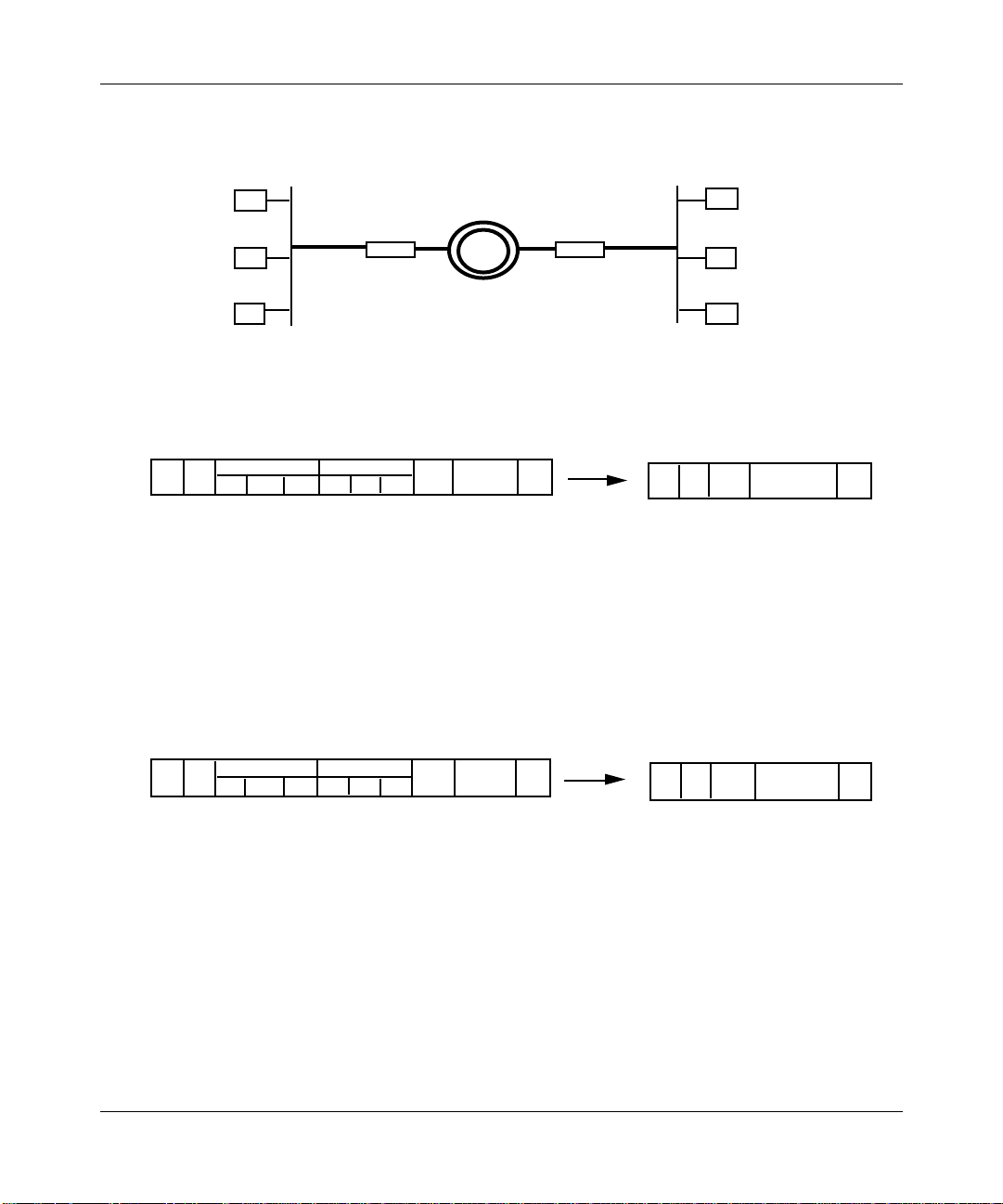
AppleTalk Address Resolution Protocol (ARP) frames (Ethernet frames with a
protocol type equal to 80F3) require special translation by the Bridge Tunnel
Service.
Figure 1-3 illustrates the LLC and SNAP headers of the AppleT alk ARP outbound
frame after the Bridge Tunnel Service translation.
DSAP SSAP Control OUI Protocol Type
0 xAA 0 xAA 03 0000F8 80F3
SNAP LLC
SNAP LLC
1-4
Key
SNAP = Subnetwork Access Protocol
LLC = logical link control
DSAP = destination service access point
SSAP = session service access point
OUI = organizationally unique identifier
Figure 1-3. Bridge Tunnel Service Encapsulation
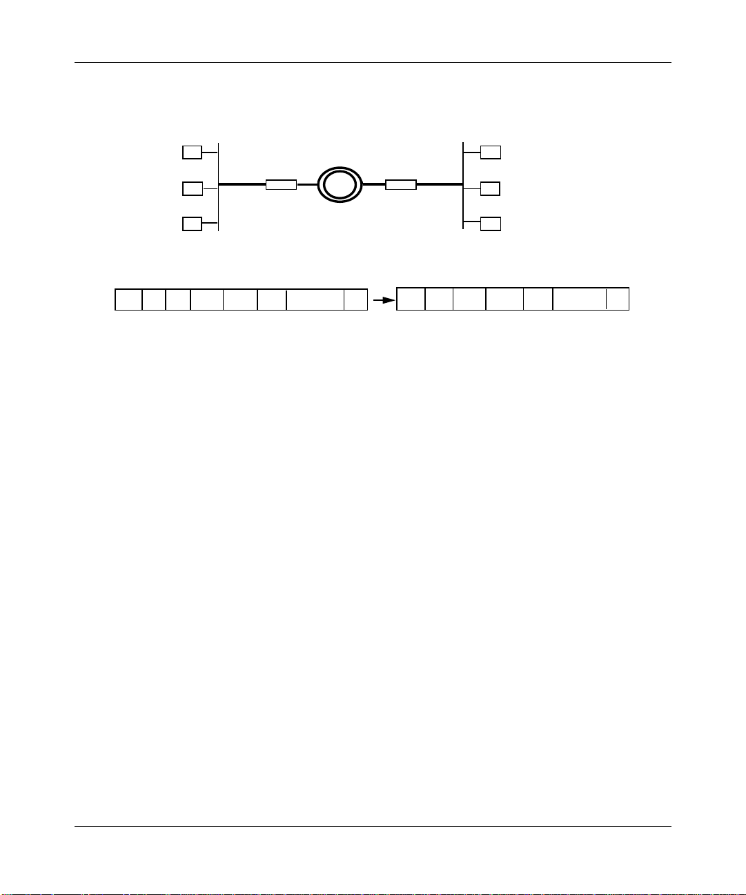
The bridge translates all IEEE 802.2 LLC frames by removing the length field.
Protocols in this category include AppleTalk Phase 2, Novell Proprietary, and IP.
Figures 1-4 and 1-6 illustrate different LAN configurations and show how Bridge
A translates different types of frames originating on LAN 1 for transmission
across the FDDI LAN. Figure 1-5 shows how Bridge B translates frames
transmitted from the FDDI LAN to LAN 2.
Page 15
Using Transparent Bridge Services
Ethernet LAN1 Ethernet LAN2
Bridge A
Bridge B
FDDI LAN
Ethernet to FDDI Translation
Through Bridge A to FDDI LANFrom Ethernet LAN
DA DA SASA
TYPE
=80F3
DATA FCS
SNAP LLC OUI
AA AA 03 00 00 00
Bridge A
• Extracts addressing information from the Ethernet header.
• Incorporates address information into newly generated FDDI MAC header.
• Encapsulates Ethernet data according to RFC 1042.
• Recalculates frame check sequence (FCS).
Ethernet (AppleTalk ARP) to FDDI Translation
From Ethernet LAN
DA SA
TYPE
=80F3
DATA FCS
Through Bridge A to FDDI LAN
DA SA
SNAP LLC OUI
AA AA 03 00 00 F8
TYPE
=80F3
TYPE
=80F3
DATA
FCSDATA
FCS
Bridge A
• Extracts addressing information from the Ethernet header.
• Incorporates address information into newly generated FDDI MAC header.
• Encapsulates Ethernet data within an IEEE 802.2H-defined SNAP header that has
an organizationally unique identifier (OUI) of 0000F8.
• Recalculates FCS.
Figure 1-4. Ethernet to FDDI Translation
1-5
Page 16
Configuring Bridging Services
Ethernet LAN1 Ethernet LAN2
Bridge A
Bridge B
FDDI LAN
FDDI to Ethernet Translation
From FDDI LAN
DA SA
SNAP LLC OUI
AA AA 03 00 00 00 =80F3
TYPE
FCSDATA
Through Bridge B to Ethernet LAN
Bridge B
• Extracts addressing information from the FDDI header.
• Incorporates address information into newly generated Ethernet MAC header.
• Removes RFC 1042 from Ethernet data.
• Recalculates frame check sequence (FCS).
FDDI to Ethernet (AppleTalk ARP) Translation
From FDDI LAN
DA SA
SNAP LLC OUI
AA AA 03 00 00 F8
TYPE
=80F3
DATA
FCS
Through Bridge B to Ethernet LAN
DA SA
DA SA
TYPE
=80F3
TYPE
=80F3
DATA FCS
DATA FCS
Bridge B
• Extracts addressing information from the FDDI header.
• Incorporates address information into newly generated Ethernet MAC header.
• Removes Ethernet data from an IEEE 802.2H-defined SNAP header that has an
organizationally unique identifier (OUI) of 0000F8.
• Recalculates FCS.
Figure 1-5. FDDI to Ethernet Translation
1-6
Page 17
Using Transparent Bridge Services
Ethernet LAN1 Ethernet LAN2
Bridge A Bridge B
FDDI LAN
802.3 to FDDI Translation
Through Bridge A to FDDI LANFrom 802.3 LAN
DA SA LEN DSAP SSAP CTL DATA FCS DA SA DSAP SSAP CTL DATA FCS
Bridge A
• Extracts addressing information from the 802.3 header.
• Incorporates address information into newly generated FDDI MAC header with no length (LEN) field.
• Encapsulates 802.3 data within FDDI frame.
• Recalculates FCS.
Figure 1-6. Ethernet/802.3 to FDDI Translation
The translation process from the FDDI LAN to Ethernet/802.3 LAN (the process
Bridge B performs in Figures 1-5 and 1-6) is a mirror image of the translation
process occurring on Bridge A, with one exception: the bridge translates an
AppleTalk ARP frame that originates on the FDDI LAN and is destined for an
Ethernet/802.3 LAN as shown in Figure 1-7.
1-7
Page 18

Configuring Bridging Services
AppleTalk ARP frame originating on FDDI LAN
DA SA
SNAP LLC OUI
AA AA 03 = 00 00 00
Through Bridge B to 802.3 LAN
DA SA
SNAP LLC OUI
LEN
AA AA 03 = 00 00 00
Bridge B
• Extracts addressing information from the FDDI MAC header
• Incorporates address information into newly generated 802.3 header
• Adds a length field
• Encapsulates FDDI data according to RFC 1042
• Recalculates FCS
Figure 1-7. AppleTalk ARP (Originating on FDDI) to 802.3 Translation
Spanning T ree Algorithm
TYPE
=80F3
TYPE
=80F3
DATA
FCS
DATA FCS
1-8
The spanning tree algorithm ensures the existence of a loop-free topology in
networks that contain parallel bridges. (Refer to
Standard 802.1d Media Access Contr ol (MAC) Bridges
Source Routing Appendix to IEEE
for details on the spanning
tree algorithm.) A loop occurs when there are alternate routes between hosts. If
there is a loop in an extended network, bridges may forward traffic indefinitely,
which can result in increased traffic and degradation in network performance.
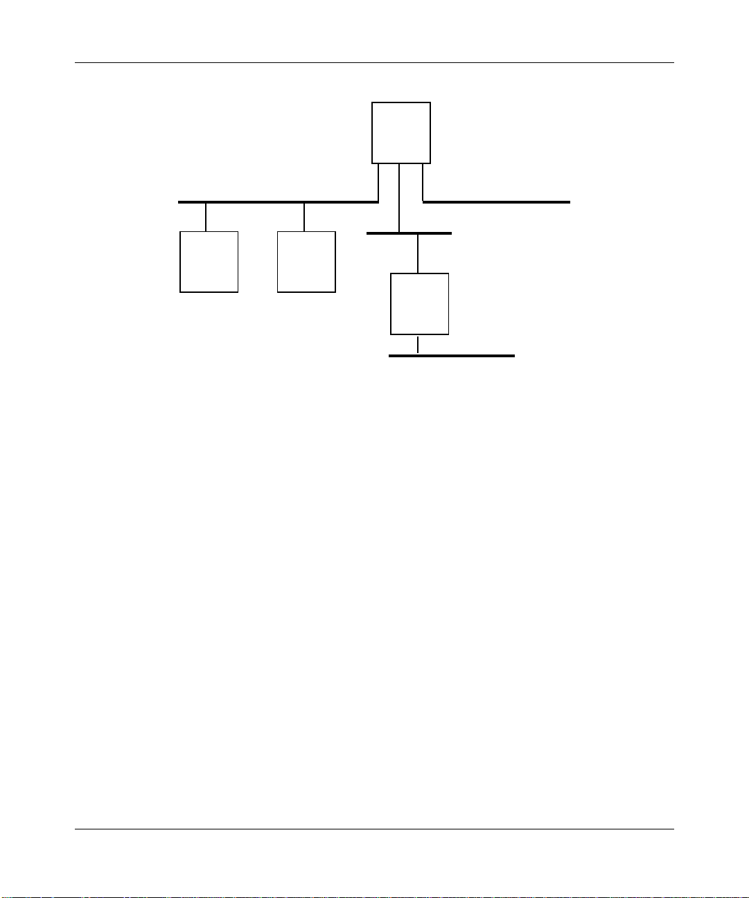
Figure 1-8 shows an example of a network containing a loop: two parallel bridges,
Bridge 1 and Bridge 2, connect LANs A and B.
Page 19
IF 9
BR 4
Using Transparent Bridge Services
LAN C
ES K
IF 5
ES J
IF 2
BR 2BR 1
IF 3
IF 6
LAN B
IF 1
IF 8
LAN A
Figure 1-8. Parallel Bridge Topology
When Endstation J initially sends a frame to Endstation K, both Bridge 1 and
Bridge 2 read the frame. Since this is the first frame sent between J and K, there is
no forwarding table entry for J or K on either of the bridges. Each bridge updates
its forwarding table to indicate that Endstation J is in the direction of LAN A.
Then, each bridge floods the frame: Bridge 1 forwards the frame over Interface 1
and Bridge 2 forwards the frame over Interface 2. Bridge 2 also forwards the
frame over Interface 3; however, to simplify the example, we do not trace this
frame.
LAN D
Key
IF = Interface
BR = Bridge
ES = Endstation
IF 7
IF 4
BR 3
1-9
Page 20

Configuring Bridging Services
Next, Endstation K receives tw o copies of the frame, resulting in an inefficient use
of the available bandwidth. More serious, however, is the effect of duplicate
frames on the two bridges. The frame flooded by Bridge 1 onto Interface 1 is
ultimately read by Bridge 2 on Interface 2. When Bridge 2 reads this frame, it
updates its forwarding table to indicate that Endstation J is in the direction of
LAN B. Similarly, Bridge 1 reads the frame flooded by Bridge 2 and updates its
forwarding table to show that Endstation J is in the direction of LAN B.
Consequently , the forwarding tables of both bridges are no w corrupted and neither
bridge can properly forward a frame to Endstation J.
You can avoid this problem by implementing the spanning tree algorithm, which
produces a logical tree topology out of any arrangement of bridges. The result is
that a single path exists between any two endstations on an extended netw ork. The
spanning tree algorithm also provides a high degree of fault tolerance. It allows
the network to automatically reconfigure the spanning tree topology if there is a
bridge or data-path failure.
The spanning tree algorithm requires five values to derive the spanning tree
topology. The first, a multicast address specifying all bridges on the extended
network, is media-dependent and is automatically determined by the software.
You assign the remaining four values, which are
1-10
• Network-unique identifier for each bridge on the extended network
• Unique identifier for each bridge/LAN interface (called a port)
• Priority specifying the relative priority of each port
• Cost for each port
After you assign these values, bridges multicast and process the formatted frames
(called Bridge Protocol Data Units, or BPDUs) to derive a single loop-free
topology throughout the extended network. The bridges exchange BPDU frames
quickly, minimizing the time that service is unavailable between hosts.
In constructing a loop-free topology, the bridges within the extended network
follow these steps:
1.
Elect a root bridge.
The bridge with the lowest priority value becomes the root bridge and serves
as the root of the loop-free topology. If priority values are equal, the bridge
with the lowest bridge MAC address becomes the root bridge.
Page 21
IF 3
Bridge A
Using Transparent Bridge Services
2.
Determine path costs.
The path cost is the cost of the path to the root bridge offered by each bridge
port.
3.
Select a root port and elect a designated bridge on each LAN.
Each bridge designates the port that offers the lowest-cost path to the root
bridge as the root port. In the event of equal path costs, the bridge examines
the paths’ interfaces to the root bridge. The port (interface) of the path with
the lowest interface priority to the root bridge becomes the root port. For
example, Figure 1-9 shows how Bridge A determines its root port.
Given:
Root
Bridge
IF 1
IF 2
LAN A
LAN B
IF 4
Path costs from IF 3 to root bridge and
from IF 4 to root bridge are equal.
---------AND-------IF 1 = priority 1
IF 2 = priority 2
IF 3 = priority 3
IF 4 = priority 4
Then:
IF 3 becomes root port because
IF 1’s priority is lower than IF 2’s
priority.
Figure 1-9. Root Port Determination (Equal Path Costs)
If the paths’ interfaces to the root bridge are also equal, then the root port is
the port on the bridge with the lowest priority value (Figure 1-10).
1-11
Page 22
Configuring Bridging Services
Given:
Path costs from IF 3 to root bridge and
from IF 4 to root bridge are equal.
---------AND-------IF 1 = priority 1
IF 2 = priority 1
IF 3 = priority 3
IF 4 = priority 2
Then:
IF 4 becomes root port because it has
a higher priority than IF 3.
Same
priority
IF 3
Bridge A
Root
Bridge
IF 1
IF 2
LAN A
LAN B
IF 4
Figure 1-10. Root Port Determination (Equal Path Costs and Root Interface Priorities)
The spanning tree algorithm selects a bridge on each LAN as the designated
bridge. The root port of this bridge has the lowest-cost path to the root bridge.
All bridges turn off (set to blocking state) all of the lines except for the single
line that is the shortest-cost path to the root and any line attached to the LANs
for which the bridge serves as a designated bridge.
1-12
4.
Elect a designated port.
The spanning tree algorithm selects the port that connects the designated
bridge to the LAN as the designated port. If there is more than one such port,
the spanning tree algorithm selects the port with the lowest priority as the
designated port. This port, which carries all extended network traffic to and
from the LAN, is in the forwarding state.
Thus, the spanning tree algorithm removes all redundant ports (ports providing
parallel connections) from service (places in the blocking state). If there is a
topological change or a bridge or data-path failure, the algorithm derives a new
spanning tree that may move some ports from the blocking to the forwarding
state.
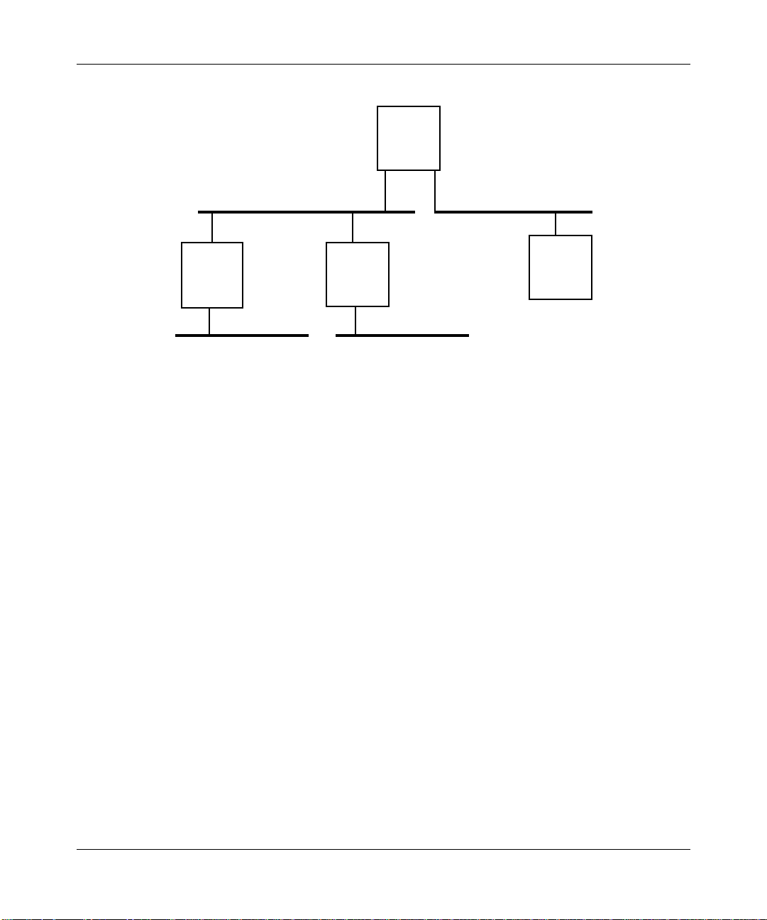
For example, in Figure 1-8, if all path costs are equal and Bridge 2 has the lowestbridge priority (followed by Bridge 3, Bridge 4, and Bridge 1), the spanning tree
algorithm may block Bridge 1/Interface 8 and Bridge 4/Interface 9 from service.
Figure 1-11 shows the resulting logical topology, which provides a loop-free
topology with only a single path between any two hosts.
Page 23
BR 2
Using Transparent Bridge Services
LAN B LAN A
IF 1
BR 4BR 1
Given:
All path costs are equal.
Interface (IF) number
denotes its priority.
----And----
BR 2 = priority 1
BR 3 = priority 2
BR 4 = priority 3
BR 1 = priority 4
IF 2 IF 3
IF 5
Then:
Bridge 1/Interface 1 is blocked.
Bridge 4/Interface 5 is blocked.
Result:
Loop-free topology
is created.
IF 6
LAN D
IF 7
BR 3
IF 8
LAN C
Figure 1-11. Spanning Tree (Loop-Free) Logical Topology
It is very important to configure the spanning tree parameters correctly. Consider
the typical flow of traffic so that the logical topology that results from the
spanning tree algorithm is appropriate for the network.
If, in the network shown in Figure 1-8, a majority of traffic originates on LAN A
and is destined for LAN D, it is not practical to set the spanning tree parameters as
shown in Figure 1-12. This figure illustrates an inefficient spanning tree topology
for this network because the traffic from LAN A must traverse Bridge 1, LAN B,
and Bridge 2 to get to LAN D. LAN B is then congested with unnecessary traffic.
1-13
Page 24
Configuring Bridging Services
BR 4
IF 5 IF 9
LAN B LAN C
BR 1
Given:
All path costs are equal.
Interface (IF) number
denotes its priority.
----And---BR 4 = priority 1
BR 3 = priority 2
BR 2 = priority 3
BR 1 = priority 4
Figure 1-12. Inefficient Spanning Tree Topology
Filtering Frames
IF 1
IF 8
LAN A
IF 2
BR 2
IF 3
LAN D
Then:
Bridge 2/Interface 2 is blocked.
Bridge 3/Interface 7 is blocked.
Result:
Inefficient spanning
tree topology is created.
IF 7
BR 3
1-14
You use filters mainly for security reasons. They enable the bridge to relay or drop
a particular frame based on user-selectable fields within each of the four
encapsulation methods supported by the bridge. These encapsulation methods are
• Ethernet
• IEEE 802.2 LLC
• IEEE 802.2 LLC with SNAP header
• Novell proprietary
Page 25

Using Transparent Bridge Services
Refer to
filters and how to configure them for the bridge.
Configuring Traffic Filters and Protocol Prioritization
Enabling Bridge Service
This section describes how to enable bridge service and, optionally, spanning tree
on an interface. It assumes you have read
1. Opened a configuration file.
2. Specified router hardware if this is a local mode configuration file.
3. Selected the link or net module connector on which you are enabling bridge
service, or configured a WAN circuit if this connector requires one.
Enabling Bridge Service on an Interface
To enable bridge service without spanning tree, select Bridge from the Select
Protocols menu and click on OK. The Select Protocols menu appears after you
either select a link or net module connector, or finish configuring a WAN circuit.
When you enable bridge service without spanning tree, you need not specify any
configuration information, because Configuration Manager supplies default values
for the bridge parameters. The protocol pop-up window for the next enabled
protocol appears, or, if only bridge is enabled on this circuit, the Bay Networks
Configuration Manager window appears. To edit the default values for the bridge
parameters, refer to “Editing Bridge Parameters” for instructions.
Configuring Routers
for details about
and that you have
Enabling Spanning Tree on an Interface
To enable spanning tree on an interface, use the following procedure.
1. From the Select Protocols menu, select the Spanning Tree option that is
directly under the Bridge option.
Note that the Configuration Manager also selects the Bridge option because
this Spanning Tree protocol cannot run without Bridge enabled.
2. Click on OK.
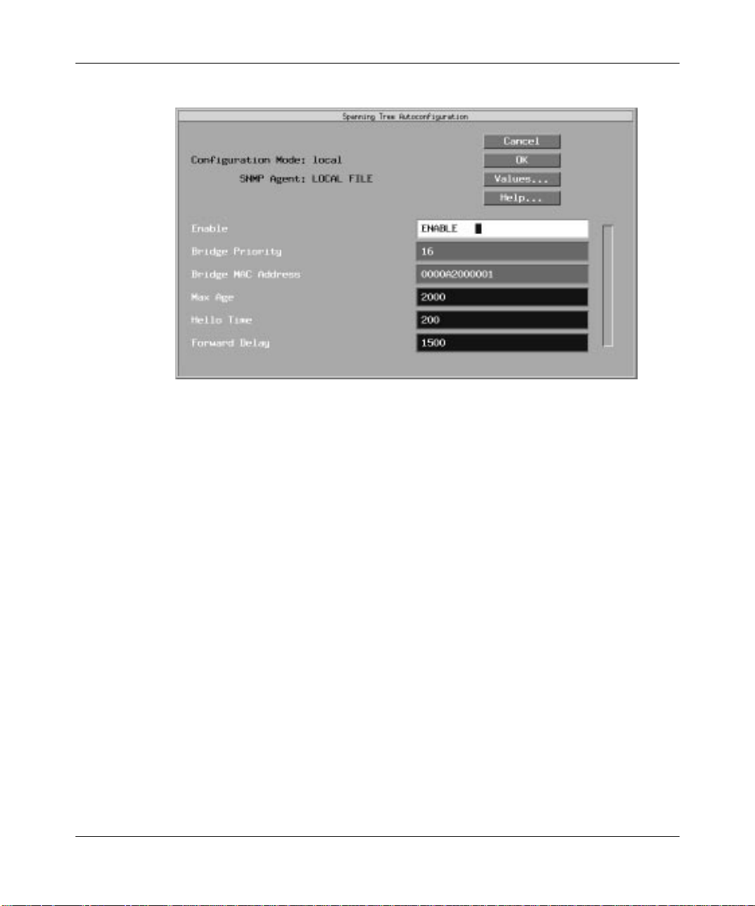
The Spanning Tree Autoconfiguration window appears (Figure 1-13).
1-15
Page 26

Configuring Bridging Services
When you enable spanning tree service, you need only configure the Bridge
Priority and Bridge MAC Address parameters. The Configuration Manager
supplies default values for the remaining parameters. If you want to edit the
default values, see “Editing Bridge Parameters” later in this section.
Note: Because the spanning tree is global (that is, it runs across all Bridge
circuits), the Configuration Manager only displays the Spanning Tree
Autoconfiguration window the first time you specify Spanning Tree for the
Bridge. If you have previously specified Spanning Tree for source routing, this
window will not appear. To change the parameter settings at a later time, r efer
to the “Editing Bridge Parameters” section.
3. Configure the parameters, using the descriptions that follow as a guide.
4. When you have configured the required parameters, click on OK.
A pop-up window prompts
Do you want to edit the Spanning Tree Interface Details?
5. Click on Cancel to enable default Spanning Tree service and display the
next protocol-specific pop-up window, or click on OK to edit the default
spanning tree values.
1-16
(Refer to “Editing Bridge Parameters” for instructions.)
Page 27
Using Transparent Bridge Services
Figure 1-13. Spanning Tree Autoconfiguration Window
Parameter: Bridge Priority
Default: 128
Range: 0 to 65535
Function: Combined with the Bridge MAC Address parameter, assigns a 64-bit
bridge ID to the router. This parameter supplies the most significant 16
bits of the bridge ID, while Bridge MAC Address supplies the remaining
(least significant) 48 bits.
The spanning tree uses the bridge ID to select the root bridge. In selecting
the root bridge, the spanning tree chooses the bridge with the lowest
bridge ID number. Thus, the lower the value you set for this parameter,
the more likely it is that the router will be selected as the root bridge.
Instructions: Enter a decimal value from 0 to 65535.
MIB Object ID: 1.3.6.1.4.1.18.3.5.1.2.1.5
1-17
Page 28

Configuring Bridging Services
Parameter: Bridge MAC Address
Default: Defaults to a unique MAC address that the router automatically creates
based on the router’s backplane ID.
Options: Any valid 48-bit MAC-level address
Function: Combined with the Bridge Priority parameter, assigns a 64-bit bridge ID
to the router. Bridge Priority supplies the most significant 16 bits of the
bridge ID, while this parameter supplies the remaining (least significant)
48 bits.
The spanning tree uses the bridge ID to select the root bridge. In selecting
the root bridge, the spanning tree chooses the bridge with the lowest
bridge ID number. Thus, the lo wer the setting of Bridge Priority, the more
likely it is that the router will be selected as the root bridge. In the event of
equal Bridge Priority values, the value of this parameter determines the
bridge’s priority.
Instructions: Enter a 48-bit MAC address expressed as a 12-digit hexadecimal value.
We recommend that you set this parameter to the MAC address of one of
the router’s spanning tree ports, preferably the one with the lowest
priority.
MIB Object ID: 1.3.6.1.4.1.18.3.5.1.2.1.5
Editing Bridge Parameters
Once you configure a circuit to support the bridge and, optionally, the spanning
tree algorithm, you use Configuration Manager to edit the bridge and spanning
tree parameters.
This section provides information on how to access and edit these parameters.
Note: If you enable the spanning tree algorithm for your network, the
algorithm reconverges if you dynamically change any of the parameters
described in the following sections.
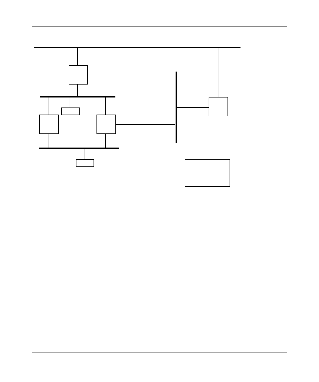
You access all bridge parameters from the Configuration Manager window
(Figure 1-14). (Refer to Using Site Manager Software guide for details on
accessing this window.)
1-18
Page 29
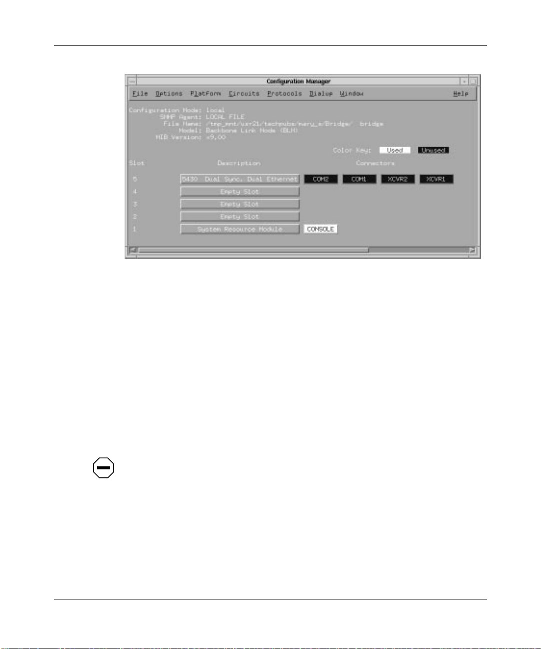
Using Transparent Bridge Services
Figure 1-14. Configuration Manager Window
For each bridge and spanning tree parameter, this section provides information
about default settings, valid parameter options, the parameter function,
instructions for setting the parameter, and the Management Information Base
(MIB) object ID.
Technician Interface lets you modify parameters by issuing
commands that specify the MIB object ID. This process is equivalent to
modifying parameters using Site Manager. For more information about using the
Technician Interface to access the MIB, refer to Using Technician Interface
Software.
Caution: The Technician Interface does not verify that the value you enter for
a parameter is valid. Entering an invalid value can corrupt your
configuration.
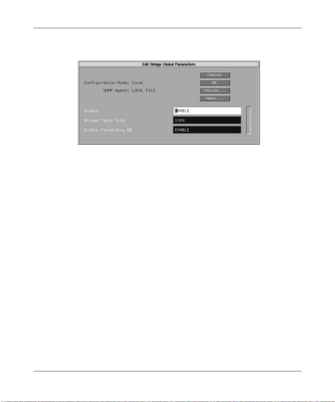
Editing Bridge Global Parameters
To edit the bridge global parameters:
1. Select Protocols➔Bridge➔Global from the Configuration Manager
window (refer to Figure 1-14).
set and commit
1-19
Page 30
Configuring Bridging Services
The Edit Bridge Global Parameters window appears (Figure 1-15).
Figure 1-15. Edit Bridge Global Parameters Window
Edit the parameters, using the descriptions in the next section as a guide.
2.
3. Click on OK to save your changes and exit the window.
Site Manager returns you to the Configuration Manager window.
Bridge Global Parameter Descriptions
Use these parameter descriptions as a guide when you configure the parameters in
the Edit Bridge Global Parameters window (refer to Figure 1-15).
Parameter: Enable
Default: Enable
Options: Enable
Function: Enables or disables bridging on the entire router.
Instructions: Set to Disable if you w ant to disable bridging for all circuits on the router.
MIB Object ID: 1.3.6.1.4.1.18.3.5.1.1.1.1.2
1-20
| Disable
Page 31

Parameter: Bridge Table Size
Default: 1024 entries
Using Transparent Bridge Services
Options: 1024
Function: Specifies the maximum number of MAC address entries allowed in the
Instructions: Specify the table size, after accounting for the number of protocols
MIB Object ID: 1.3.6.1.4.1.18.3.5.1.1.1.1.5
| 2048 | 4096 | 8192 | 16384 | 32768 | 65536 | 131072
forwarding table. If you enter an invalid value, the system rounds up or
down from the invalid value to the nearest valid value.
If you increase the number of table entries, the bridge is more efficient but
uses more memory.
If you save a change to this parameter in dynamic mode, the bridge
disables and then re-enables itself, thereby deleting all previously learned
addresses.
running on your router and the size of the bridged network. The
translation bridge, if configured, also adds addresses to this forwarding
table. Therefore, if you configure the translation bridge, remember to
account for the number of addresses it learns from the source route
network.
Select the 131072 option only if the router is running IP Host Only and no
other protocols are running on the router. If you select 131072, the system
automatically disables the next parameter, Enable Forwarding DB.
1-21
Page 32

Configuring Bridging Services
Parameter: Enable Forwarding DB
Default: Enable
Options: Enable
Function: If you enable this parameter, the bridge maintains an additional table,
equal in size to the forwarding table plus dynamically allocated memory
for each MAC address. This additional table contains each MAC address
in the forwarding table and the port from which the bridge learned the
address. The table allows you to access MAC addresses and ports via the
MIB.
If you change the setting of this parameter in dynamic mode, the bridge
disables and re-enables itself. If you change the setting to Disable, the
bridge deletes all previously learned addresses, including those in the
forwarding table.
Instructions: Leave this parameter enabled if you want to view the MAC addresses in
the forwarding table or the ports from which the bridge learned the
addresses.
Disable this parameter if you need to improve bridge performance.
MIB Object ID: 1.3.6.1.4.1.18.3.5.1.1.1.1.6
| Disable
Editing Bridge Interface Parameters
To edit bridge interface parameters:
1-22
1. Select Protocols➔Bridge➔Interfaces from the Configuration Manager
window (refer to Figure 1-14).
The Bridge Interfaces window appears (Figure 1-16).
Page 33

Using Transparent Bridge Services
Figure 1-16. Bridge Interfaces Window
Select the interface you want to edit.
2.
3. Edit the parameters, using the descriptions in the next section as a guide.
4. Click on Apply to save your changes.
5. Click on Done to exit the window.
Site Manager returns you to the Configuration Manager window.
Bridge Interface Parameter Descriptions
Use these parameter descriptions as a guide when you configure the parameters in
the Bridge Interfaces window (refer to Figure 1-16).
1-23
Page 34

Configuring Bridging Services
Parameter: Enable
Default: If you added bridging using either the Quick-Start procedure or the
configuring-circuits procedure, this parameter defaults to Enable. If you
previously used this parameter to disable bridging on this circuit, the
parameter defaults to Disable.
Options: Enable
Function: Toggles bridging on and off for this circuit only.
Instructions: This parameter does not allow you to add bridging to this circuit. To add
the bridging protocol to this circuit, you must use the Configuration
Manager (see Configuring Routers).
Set this parameter to either Enable or Disable.
MIB Object ID: 1.3.6.1.4.1.18.3.5.1.1.3.1.2
Parameter: Translational Bridge Enable
Default: Disable
Options: Enable
Function: Specifies whether this transparent bridge interface participates in a
transparent-to-source-routing translation-bridged network. Make sure you
enable only one interface for translation bridging and that you disable this
parameter for all other interfaces. Otherwise, translation bridging does not
occur.
Instructions: Set this parameter to Enable or Disable, depending on your interface.
MIB Object ID: 1.3.6.1.4.1.18.3.5.1.1.3.1.9
| Disable
| Disable
Editing Spanning Tree Global Parameters
To edit the spanning tree global parameters:
1. Select Protocols➔Bridge➔Spanning Tr ee➔Global from the
Configuration Manager window (refer to Figure 1-14).
The Edit Spanning Tree Global Parameters window appears (Figure 1-17).
1-24
Page 35

Using Transparent Bridge Services
Figure 1-17. Edit Spanning Tree Global Parameters Window
Edit the parameters, using the descriptions in the next section as a guide.
2.
3. Click on OK to save your changes and exit the window.
Site Manager returns you to the Configuration Manager window.
Spanning Tree Global Parameter Descriptions
Use these parameter descriptions as a guide when you configure the parameters in
the Edit Spanning Tree Global Parameters window (refer to Figure 1-17).
Parameter: Enable
Default: Enable
Options: Enable
Function: Enables or disables spanning tree on the entire router.
Instructions: Set to Disable if you want to disable spanning tree for the entire router, or
to Enable if you want to enable spanning tree for the entire router.
MIB Object ID: 1.3.6.1.4.1.18.3.5.1.2.1.2
| Disable
1-25
Page 36

Configuring Bridging Services
Parameter: Bridge Priority
Default: 128
Range: 0 to 65535
Function: Combined with the Bridge MAC Address parameter, assigns a 64-bit
bridge ID to the router. This parameter supplies the most significant 16
bits of the bridge ID, while Bridge MAC Address supplies the remaining
(least significant) 48 bits.
The spanning tree uses the bridge ID to select the root bridge. In selecting
the root bridge, the spanning tree chooses the bridge with the lowest
bridge ID number. Thus, the lower the value you set for this parameter,
the more likely it is that the router will be selected as the root bridge.
Instructions: Enter a decimal value from 0 to 65535.
MIB Object ID: 1.3.6.1.4.1.18.3.5.1.2.1.5
Parameter: Bridge MAC Address
Default: Defaults to a unique MAC address that the router automatically creates
based on the router’s backplane ID.
Options: Any valid 48-bit MAC-level address
Function: Combined with the Bridge Priority parameter, assigns a 64-bit bridge ID
to the router. Bridge Priority supplies the most significant 16 bits of the
bridge ID, while this parameter supplies the remaining (least significant)
48 bits.
The spanning tree uses the bridge ID to select the root bridge. In selecting
the root bridge, the spanning tree chooses the bridge with the lowest
bridge ID number. Thus, the lo wer the setting of Bridge Priority, the more
likely it is that the router will be selected as the root bridge. In the event of
equal Bridge Priority values, the value of this parameter determines the
bridge’s priority.
Instructions: Enter a 48-bit MAC address expressed as a 12-digit hexadecimal value.
We recommend that you set this parameter to the MAC address of one of
the router’s spanning tree ports, preferably the one with the lowest
priority.
MIB Object ID: 1.3.6.1.4.1.18.3.5.1.2.1.5
1-26
Page 37

Using Transparent Bridge Services
Caution: We recommend that you not change the following three spanning
tree parameters (Max Age, Hello Time, and Forward Delay) unless absolutely
necessary. However, if you do change them, you must follow these guidelines:
2 x (Forward Delay – 1 Second) ≥ Max Age
Max Age ≥ 2 x (Hello Time + 1 Second)
If the values for Max Age, Hello Time, and Forward Delay are not the
same for each bridge in your network, the root bridge parameters rule the
entire topology.
Parameter: Max Age
Default: 20 seconds (expressed in hundredths of a second: 2000)
Range: 6 to 40 seconds
Function: Specifies the maximum number of seconds that the router considers
protocol information (BPDUs) valid. After this specified amount of time,
the router times out and discards the information.
We recommend that you accept the default value; however, if you change
it, you must follow the guidelines listed previously in this section.
Instructions: Either accept the default value or specify a new value. Make sure to
express any new value in hundredths of a second.
MIB Object ID: 1.3.6.1.4.1.18.3.5.1.2.1.15
1-27
Page 38

Configuring Bridging Services
Parameter: Hello Time
Default: 2 seconds (expressed in hundredths of a second: 200)
Range: 1 to 10 seconds
Function: Specifies the interval in seconds between BPDUs transmitted by the
bridge. BPDUs are periodic transmissions exchanged between bridges in
the network to convey configuration and topology change data.
We recommend that you accept the default value; however, if you change
it, you must follow the guidelines listed previously in this section.
Instructions: Either accept the default value or enter a new value. Make sure you enter
the new value in hundredths of a second.
MIB Object ID: 1.3.6.1.4.1.18.3.5.1.2.1.16
1-28
Page 39

Using Transparent Bridge Services
Parameter: Forward Delay
Default: 15 seconds (expressed in hundredths of a second: 1500)
Range: 4 to 30 seconds
Function: Specifies the time in seconds that a circuit spends in the listening and
learning states. If you set this parameter to the minimum value, the
spanning tree converges at its fastest rate.
As the spanning tree algorithm operates, it eventually places all circuits in
either a forwarding (enabled) or blocking (disabled) state. In response to
network topology changes, the spanning tree algorithm may change the
state of specific circuits. To prevent network looping caused by sudden
state changes, the spanning tree algorithm does not change circuits
directly from the blocking to the forwarding state. Rather, it places them
in two intermediate states: listening and learning.
In the listening (standby) state, the circuit listens for network-generated
BPDUs. It receives and drops all other traffic. When the forward delay
timer expires, the spanning tree algorithm places the circuit in the
learning state.
In the learning state, the circuit receives both network-generated BPDUs
and endstation-generated traffic that is subjected to the learning process
but is not relayed. When the forward delay timer expires, the spanning
tree algorithm places the circuit in the forwarding state.
We recommend that you accept the default, 15 seconds; however, if you
change the value, you must follow the guidelines listed previously in this
section.
Instructions: Either accept the default value or enter a new value. Make sure you enter
the new value in hundredths of a second.
MIB Object ID: 1.3.6.1.4.1.18.3.5.1.2.1.17
Editing Spanning Tree Interface Parameters
To edit spanning tree interface parameters:
1. Select Protocols➔Bridge➔Spanning Tr ee➔Interfaces from the
Configuration Manager window (refer to Figure 1-14).
The Spanning Tree Interfaces window appears (Figure 1-18).
1-29
Page 40

Configuring Bridging Services
Figure 1-18. Spanning Tree Interfaces Window
Select the interface you want to edit.
2.
3. Edit the parameters, using the descriptions in the next section as a guide.
4. Click on Apply to save your changes.
5. Click on Done to exit the window.
Site Manager returns you to the Configuration Manager window.
Spanning Tree Interface Parameter Descriptions
Use these parameter descriptions as a guide when you configure the parameters on
the Spanning Tree Interfaces window (refer to Figure 1-18).
1-30
Page 41

Using Transparent Bridge Services
Parameter: Enable
Default: If you added spanning tree using either the Quick-Start procedure or the
configuring-circuits procedure, this parameter defaults to Enable. If you
previously used this parameter to disable spanning tree on this circuit, the
parameter defaults to Disable.
Options: Enable
Function: Toggles spanning tree on and off for this circuit only.
Instructions: This parameter does not allow you to add spanning tree to this circuit. To
add the spanning tree to this circuit, you must use the Configuration
Manager. (Refer to Configuring Routers for details.)
Instructions: Set this parameter to Enable or Disable.
MIB Object ID: 1.3.6.1.4.1.18.3.5.1.2.2.1.2
Parameter: Priority
Default: 128
Range: 0 to 255
Function: Assigns a priority to a bridge port. This interface priority value and the
bridge ID (bridge priority + bridge MAC address) determine whether this
port becomes the designated port when the spanning tree algorithm
converges. The lower the priority value, the higher the priority, and the
more likely it is that this port will be the designated port.
Instructions: Either accept the default value or enter a new value.
MIB Object ID: 1.3.6.1.4.1.18.3.5.1.2.2.1.4
| Disable
1-31
Page 42

Configuring Bridging Services
Parameter: Path Cost
Default: 1
Range: 1 to 65535
Function: When this port is the root port, the path cost is the contribution of the path
through this port to the total cost of the path to the root for this bridge.
When this port is not the root port, the path cost is added to the designated
cost for the root port and is used as the value of the root path cost offered
in all configuration BPDUs transmitted by the bridge.
To determine the path cost, use this formula:
Interface Path Cost = 1000/Attached LAN speed in Mb/s
Instructions: Enter a path cost value. For example, enter 100 if the attached LAN is
Ethernet (1000/10 = 100).
MIB Object ID: 1.3.6.1.4.1.18.3.5.1.2.2.1.7
Flushing the Forwarding Table
You can clear (flush) all MAC addresses from the bridge’s forwarding table
without bringing the bridge down and back up. This function is only available
when you configure the bridge in dynamic mode.
To flush the tables, select Protocols➔Bridge➔Flush FWD Tables from the
Configuration Manager window (refer to Figure 1-14). The system unlearns all
MAC addresses it previously stored in its forwarding table and then displays a
confirmation message.
Deleting the Bridge and Spanning Tree from the Router
To delete the bridge or spanning tree from all Bay Networks router circuits on
which you enabled them, begin at the Configuration Manager window (refer to
Figure 1-14):
1. To delete the bridge and spanning tree, select Protocols➔Bridge➔Delete
Bridge. To delete the spanning tree only, select
Protocols➔Bridge➔Spanning T r ee➔Delete Spanning Tree.
A confirmation window appears asking whether you really want to delete the
bridge or spanning tree.
2. Click on OK.
1-32
Page 43

Using Transparent Bridge Services
Site Manager returns you to the Configuration Manager window.
The bridge and/or spanning tree is no longer configured on the Bay Networks
router.
1-33
Page 44

Page 45

Chapter 2
Using Source Routing Bridge Services
This chapter
• Contains an overview of source routing technology
• Describes how the Bay Networks source routing bridge works
• Includes a list of additional source routing reference material
• Lists implementation guidelines for adding source routing bridges to your
network
• Describes how to enable source routing services on an interface
• Describes how to edit source routing parameters and delete source routing
from the router
Source Routing Overview
Source routing networks consist of LAN segments connected by source routing
bridges (Figure 2-1).
ES 1
Internal
LAN ID = 100
Ring ID = 1
Group ID = FFF
Bridge ID = A
Figure 2-1. Source Routing Network
Bridge A
21
Bridge B
Internal
LAN ID = 102
Group ID = FFF
Bridge ID = A
3
ES 1
2-1
Page 46

Configuring Bridging Services
Each LAN segment has a unique network-wide identification number, or ring ID.
Each source routing bridge also has an identification number, or bridge ID, and a
unique network-wide internal or virtual LAN identification number, called an
internal LAN ID.
For each Bay Networks source routing bridge in the network, you assign an
additional routing identifier called a group LAN ID. The group LAN ID serves as
a routing information field (RIF) placeholder and Bay Networks identifier.
How Source Routing Differs from Transparent Bridging
The Bay Networks source routing bridge differs from the Bay Networks
transparent bridge (described in Chapter 1) in two ways:
• Source routing bridges can tolerate multiple paths between endstations in an
extended network; transparent bridges require loop-free topologies.
• Source routing bridges require endstations to supply the bridging information
needed to deliver a frame to a destination; transparent bridges use forwarding
tables.
How Endstations on a Source Routing Network Discover Routes
The following sections describe the three processes that endstations on a source
routing network use to learn the routes to destinations: all-paths broadcast routing,
spanning tree broadcast routing, and specific routing.
All-Paths Broadcast Routing
An endstation that is configured for all-paths broadcast routing generates multiple
frames that traverse all paths between source and destination endstations. These
frames are all-routes explorer (ARE) or all-paths explorer (APE) frames.
When an endstation receives an ARE frame, a bridge within the source routing
network appends a routing designator that identifies the incoming ring ID, internal
LAN ID/bridge ID, and outgoing ring ID (Figure 2-2). For information on the
spanning tree algorithm, refer to Chapter 1.
2-2
Page 47

Using Source Routing Bridge Services
Incoming Ring ID
Internal LAN ID/Bridge ID
Outgoing Ring ID
001A 100A 0020 data...
Figure 2-2. Source Routing Designator
After the bridge adds the routing designator, the other bridges send the frame out
all ports (floods the frame). As a result, multiple copies of the same ARE frame
can appear on a LAN, and the frame recipient can receive multiple copies of the
frame (one copy for each possible path through the extended network).
Each ARE frame received by the destination endstation contains a unique
sequenced list of routing designators tracing the frame’s path through the source
routing network.
Note: In a looped topology, the originating bridge may receive the ARE
frame; the originating bridge discards the frame.
Spanning Tree Broadcast Routing
An endstation configured for spanning tree broadcast routing generates a single
frame that follows a loop-free path from source to destination. This frame is a
spanning tree explorer (STE).
When an endstation generates an STE frame, each bridge on the spanning tree
forwards the frame onto all active (nonblocked) ports, except the port that
received the frame. With spanning tree broadcast routing, one copy of the STE
appears on each LAN and the frame recipient receives a single copy only.
2-3
Page 48

Configuring Bridging Services
Specific Routing
When an endstation receives an ARE or STE frame, it generates a single frame,
called a specifically routed frame (SRF). The SRF tra verses a specific path back to
the source endstation; it contains a list of routing designators that maps a path
through the extended network from source to destination.
When an endstation receives an SRF, each bridge between the source and
destination examines the list of routing designators. The bridge forwards the SRF
only if the bridge itself is on the specified path. Otherwise, it ignores the frame.
When the SRF reaches the original source endstation, that station removes the
routing information and stores it in its internal routing table.
Once the endstations discover a route and store the information in their routing
tables, the endstations send specifically routed frames across the source routed
network (Figure 2-3).
ES 1
All-Paths Explorer or Spanning Tree Explorer
Specifically Routed Frame
ES 1
Specifically Routed Frame
ES 1
Figure 2-3. Route Discovery
Source Routing over IP Networks
The Bay Networks source routing bridge supports Internet Protocol (IP)
encapsulation. IP encapsulation allows the source routing bridge to route frames
to endstations located across an IP backbone network.
These frames use standard IP transmission services and a proprietary sequence
maintenance protocol that ensures error-free, in-sequence delivery of IP
encapsulated frames. The IP network can consist of any standard IP equipment
and media.
ES 2
ES 2
ES 2
2-4
Page 49

How IP Encapsulation Works
When you enable IP encapsulation on a source routing bridge (thus making it an
IP encapsulating bridge), you assign a single ring ID to the entire IP backbone
network. The source routing bridge assigns only a single route descriptor to the
frame’s RIF to describe the entire internet, regardless of the IP network size that
the frame traverses. Therefore, frames source routed over large IP networks can
remain within maximum hop count restrictions.
Whenever a Bay Networks source routing bridge receives an explorer frame, the
bridge sends it toward an IP encapsulating bridge, which resides at the edge of the
IP backbone network. (For example, in Figure 2-4, Bridges A, B, and C are IP
encapsulating bridges.) The IP encapsulating bridge encloses the source routed
frame within an IP header before it sends the frame out onto the network. When
the frame reaches a peer IP encapsulating bridge, the bridge removes the
encapsulation from the frame and sends it out the appropriate source routing
interfaces.
Each IP encapsulating bridge maintains a dynamic mapping of destination IP
addresses to the ring and bridge IDs of their directly attached rings. When an IP
encapsulating bridge receives a source routed frame, it performs these steps:
Using Source Routing Bridge Services
1. Checks the frame’s RIF for the ring and bridge ID that immediately follow the
IP network ring and bridge ID in the RIF.
2. Looks up the IP address that corresponds with this ring and bridge ID.
3. Encapsulates the frame in an IP packet with the destination IP address.
4. Sends the frame out onto the IP network.
For example, Figure 2-4 shows the IP mapping table for IP Encapsulating
Bridge A.
2-5
Page 50

Configuring Bridging Services
IP Explorer List Bridge A
1.1.2.2
1.1.3.3
for redundancy
1.1.5.5
1.1.1.1
1
Bridge A
IP Explorer List Bridge B
1.1.1.1
1.1.5.5
IP Network
Ring ID = 2
1.1.2.2 1.1.3.3
Bridge B
6
Bridge D
IP Explorer List Bridge C
1.1.1.1
1.1.2.2
1.1.3.3
Bridge C
1.1.5.5
54
7
3
IP Mapping Table for Bridge A
Ring ID Bridge ID IPAddress
3 C 1.1.5.5
4 B 1.1.2.2
5 B 1.1.3.3
6 B (Outgoing IP Interface to the IP Network
Address on Bridge B. IP chooses the IP
interface with the IP routing protocol.)
Note that you can reach Ring 7 by normal SRB from Bridge B.
Figure 2-4. Source Routing over an IP Network
2-6
Page 51

Using Source Routing Bridge Services
When Bridge A receives a source routed frame destined for an endstation on Ring
4, it examines the frame’s RIF and locates the next ring ID (4) that immediately
follows the IP network ring ID (2), as shown in Figure 2-5.
IP Network Ring ID
Next Ring ID
MAC
RIF of an IP Encapsulated Frame
Source IP Address
1.1.1.1
RIF of an IP Encapsulated Frame
Figure 2-5. Examining the RIF Field of an SRF
001A 100A data... 0040
Destination IP Address
1.1.2.2
MAC
002B
001A 002A FFFA
Bridge A also e xamines the RIF to locate the bridge ID associated with the remote
bridge used to reach Ring 4 (in this case, Bridge B). Then, Bridge A checks its
mapping table for the IP address that corresponds to Ring ID 4 and Bridge B, and
encapsulates the frame with an IP header. The IP header specifies its own source
address, and the proper IP destination address (1.1.2.2). Finally, Bridge A
forwards the packet onto the IP network.
0040
data...
You control which IP interfaces receive explorer frames by defining an IP
Explorer list for each IP encapsulating bridge. For example, all of the IP
encapsulating bridges that border the IP cloud in Figure 2-4 have IP explorer lists
defined. Each bridge forwards explorer packets that are in its individual list
toward the IP addresses. Note that the IP explorer lists for each bridge can vary.
This allows you to control which IP networks receive explorer traffic.
2-7
Page 52

Configuring Bridging Services
IP Encapsulation Features
Bay Networks implementation of IP encapsulation allows you to:
• Configure redundant IP interfaces.
You can configure redundant IP interfaces on the same router for critical
network connections (for example, interfaces 1.1.2.2 and 1.1.3.3 on Bridge
B). That way, if you disable one of the interfaces, the other interface can still
accept IP traffic for the network. (When you enable redundant IP interfaces,
you also increase explorer traffic on the network. Therefore, enable redundant
interfaces selectively to reduce the impact on your network performance.)
• Expand your IP backbone network.
You can expand your IP backbone to include any Bay Networks IP router on
the network. You specify the router’s IP address in the IP explorer list for each
bridge.
For example, Bridge A currently forwards all traffic destined for Ring 7 to IP
interface 1.1.3.3. That router then forwards the traffic toward Ring 6 so that
the router can source route it to Ring 7. If you add IP address 1.1.4.4. to the IP
Explorer list for Bridge A, then Bridge A forwards all traffic destined for Ring
7 directly to IP interface 1.1.4.4. By expanding your IP backbone, the source
routing bridge can route through more stations, but it still can only add a
single hop to a packet’s RIF.
2-8
• Reduce excess broadcast traffic on your IP network.
You can reduce the number of broadcast and explorer packets that traverse the
network by constructing directed explorer filters. (Refer to Configuring
Traffic Filters and Protocol Prioritization for information on how to create
filters that forward IP explorer frames to specific addresses.)
• Configure both IP encapsulation support and source route endstation support
on the same interface.
IP encapsulation support works independently of source route endstation
support. However, you can enable both on the same circuit.
Page 53

Source Route Endstation Support
The Bay Networks routers running IP, IPX, XNS, AppleTalk, and VINES
protocols support support routing over Token Ring networks that contain one or
more source routing bridges. This feature is called source route endstation
support.
In a source routing network, every endstation that sends out a frame supplies the
frame with the necessary route descriptors so that the router can source route it
across the network. Thus, for routers to route packets across a source routing
network, they must act like endstations; the routers must supply route descriptors
for each packet before they send it out onto the network.
When you enable end-node support and a Bay Networks router running IP, IPX,
XNS, AppleTalk, or VINES receives a packet and determines that the packet’s
next hop is across a source routing network, the router performs these steps:
1. Adds the necessary RIF information to the packet’s MAC header
2. Sends the packet out onto the network where it is source routed toward the
next hop
Using Source Routing Bridge Services
When the peer router receives the packet from the Token Ring network, it strips
off the RIF field and continues to route the packet toward the destination network
address (Figure 2-6).
You configure source route end-node support for each individual routing protocol
on a per-circuit basis.
2-9
Page 54

Configuring Bridging Services
ES 1
Router 1 Router 2
WF ES1 SNAP IP DATA
Bridge A
1
Packet Sent from ES1
Bridge B
2
3
Source Route RIF
WF2 WF1
ES2 WF2
0830 001A 002B 0030
SNAPIPIP
DATA
SNAP
Packet Sent from Router 2
DATA
Packet Sent from Router 1
Figure 2-6. IP Routers Source Routing across a Token Ring Network
How the Bay Networks Source Routing Bridge Works
ES 2
2-10
This section shows examples of how the Bay Networks source routing bridge
routes frames through a Token Ring network. It also describes how the source
routing bridge routes frames across an IP backbone network (called IP
encapsulation).
Page 55

Source Routing across a Token Ring Network
The Bay Networks source routing bridge handles incoming packets differently,
depending on the source routing bridge’s position in the Token Ring network. To
demonstrate, the following sections describe the routing information field (RIF) of
a frame as it moves back and forth between Endstation 1 (ES1) and Endstation 2
(ES2) (Figure 2-7).
Using Source Routing Bridge Services
Example A Example B
ES 1 Bridge A Bridge B Bridge C
1
Internal
LAN ID = 100
Internal
Group ID = FFF
Bridge ID = A
2
Internal
LAN ID = 101
Internal
Group ID = FFF
Bridge ID = A
Example C
Internal
LAN ID = 102
Internal
Group ID = FFF
Bridge ID = A
Figure 2-7. Tracking an Explorer Frame
First, we track the RIF of an explorer frame sent from ES1 to ES2. Then, we track
the RIF of a specifically routed frame sent back from ES2 to ES1.
The size of the RIF is variable. It contains the routing information required to
transmit the frame across the network.
Although the following examples show only the Bay Networks source routing
bridge, other IBM-compatible source routing bridges can reside in the same
network.
43
ES 2
2-11
Page 56

Configuring Bridging Services
How the Source Routing Bridge Handles Explorer Frames
This section provides instructions on how the Bay Networks source routing bridge
handles explorer frames (AREs or STEs) sent from ES1 to ES2 (refer to
Figure 2-7). Each bridge’s internal LAN ID, group LAN ID, and bridge ID is in
hexadecimal format below the bridge.
• Example A describes the actions of the first Bay Networks bridge.
• Examples B and C describe the actions of other Bay Networks bridges in the
explorer frame’s path.
Example A: First bridge to receive the explorer frame
The frame received by Bridge A from Ring 1 did not traverse any other bridges.
This bridge adds the following information in the RIF before it transmits the
frame toward Ring 2 (Figure 2-8):
• Incoming ring ID/bridge ID
• Internal LAN ID/bridge ID
• Outgoing ring ID/bridge ID 0
2-12
Examples B and C: Other bridges that receive the explorer frame
The explorer frame received by Bridges B and C contains internal LAN IDs and
bridge numbers, indicating that this frame traversed at least one other Bay
Networks bridge. These bridges perform the following steps in the RIF before
transmitting the frame toward Rings 3 and 4 (Figure 2-8):
1. Remove the last internal LAN ID
2. Replace the incoming ring ID and bridge ID 0 with its own bridge ID
3. Add its own internal LAN ID/bridge ID
4. Add the outgoing ring ID/bridge ID 0
Page 57

ES2 ES1 8270 DSAP SSAP DATA
Frame received by Bridge A
ES2 ES1 8830 001A 100A 0020 DSAP SSAP DATA
Frame sent out by Bridge A onto Ring 2
Using Source Routing Bridge Services
Destination system MAC address
Source system MAC address
Routing control field
Data
Incoming Ring ID/Bridge ID
LAN ID/Bridge ID
Outgoing Ring ID/Bridge ID of 0
Incoming Ring ID/Bridge ID
LAN ID/Bridge ID
Outgoing Ring ID/Bridge ID of 0
ES2 ES1 8A30 001A 002A 101A 0030 DSAP SSAP DATA
Frame sent out by Bridge B onto Ring 3
ES2 ES1 8C30 001A 002A 003A 102A 0040 DSAP SSAP DATA
Frame sent out by Bridge C onto Ring 4
Figure 2-8. Structure of an Explorer Frame
Incoming Ring ID/Bridge ID
LAN ID/Bridge ID
Outgoing Ring ID/Bridge ID of 0
2-13
Page 58

Configuring Bridging Services
How the Source Routing Bridge Handles Specifically Routed Frames
This section describes how the Bay Networks source routing bridge handles
specifically routed frames (SRFs) sent from ES2 to ES1. Depending on the
bridge’s position in the network, the bridge handles the SRFs differently
(Figure 2-9).
Example A Example B
ES 1 Bridge A Bridge B Bridge C
1
Internal
LAN ID = 100
Internal
Group ID = FFF
Bridge ID = A
2
Internal
LAN ID = 101
Internal
Group ID = FFF
Bridge ID = A
Example C
Internal
LAN ID = 102
Internal
Group ID = FFF
Bridge ID = A
Figure 2-9. Tracking a Specifically Routed Frame from ES2 to ES1
If there is only a single bridge ID in the RIF, then the Bay Networks bridge
transmits the frame to the outgoing circuit without modification. This is true only
when the frame traverses a single Bay Networks bridge (or any combination of
third-party bridges) between the source and destination endstation.
If there are multiple bridge IDs in the RIF, then:
• Example A describes the actions of a Bay Networks bridge if it is the first
bridge to handle the SRF.
43
ES 2
2-14
• Example B describes the actions of a Bay Networks bridge if there are
multiple bridge IDs in the RIF , and the bridge is between the first and last Bay
Networks bridge to handle the SRF.
• Example C describes the actions of a Bay Networks bridge if there are
multiple bridge IDs in the RIF, and the bridge is the last Bay Networks bridge
to handle the SRF.
Page 59

Using Source Routing Bridge Services
Example A: First of several bridges to receive the SRF
The frame received by Bridge C from Ring 4 did not traverse any other Bay
Networks bridges (but there are multiple bridge IDs in the RIF, so it will
eventually). This bridge performs the following steps in the RIF before it
transmits the frame toward Ring 3 (Figure 2-10):
1. Changes the destination system’s MAC address at the beginning of the frame
to a Bay Networks group address.
This address is C000A2FFFFFFx, where x is the bridge ID of the next Bay
Networks bridge specified by the RIF.
2. Removes its own internal LAN ID and inserts the group LAN ID before the
last incoming ring and bridge ID listed in the RIF (Figure 2-10).
Eventually, the internal LAN ID of the last Bay Networks bridge along the
frame’s path replaces the group LAN ID.
3. Copies the destination system’s MAC address into the data portion of the
frame.
Example B: Between the first and last bridges to receive the SRF
The frame received by Bridge B from Ring 3 traversed at least one other Bay
Networks bridge. Howev er, this is not the last Bay Networks bridge that the frame
must traverse. This bridge performs the following steps in the RIF before
transmitting the frame toward Ring 2 (Figure 2-10):
1. Locates the bridge ID, which is at the end of the group address.
2. Changes the bridge ID at the end of the group address to the bridge ID of the
next Bay Networks bridge in the RIF. (Only if it differs from the v alue already
in place. In this example, all bridge IDs are the same, so the frame is not
modified.)
Example C: Last of several bridges to receive the SRF
The frame received by Bridge A is the last of several Bay Networks bridges
traversed by the frame. This bridge performs the follo wing steps in the RIF before
it transmits the frame toward Ring 1 (Figure 2-10):
1. Replaces the Bay Networks group address with the destination MAC address
that was saved to the data field
2. Replaces the group LAN ID with its own internal LAN ID
2-15
Page 60

Configuring Bridging Services
Destination MAC address
Outgoing Ring ID/Bridge ID
LAN ID/Bridge ID
Incoming Ring ID/Bridge ID of 0
ES1 ES2 0CB0 001A 002A 003A 102A 0040 DSAP SSAP DATA
Frame received by Bridge C
Bay Networks group address
Next Bridge ID
Group LAN ID
Copy of destination MAC address
C000A2FFFFFA ES2 0CB0 001A FFFA 002A 003A 0040 DSAP SSAP DATA ES1
Frame sent out by Bridge C onto Ring 3
Bay Networks group address
Next Bridge ID
C000A2FFFFFA ES2 0CB0 001A FFFA 002A 003A 0040 DSAP SSAP DATA ES1
Frame sent out by Bridge B onto Ring 2
Saved destinatin MAC address
LAN ID/Bridge ID
ES1 ES2 0CB0 001A 100A 002A 003A 0040 DSAP SSAP DATA
Frame sent out Bridge A onto Ring 1
Figure 2-10. Structure of a Specifically Routed Frame from ES2 to ES1
2-16
Page 61

Source Routing across an IP Network
This section provides details on how IP encapsulation works by tracing a
specifically routed frame as it is sent out from Endstation 1, traverses several
bridges and an IP network, and finally arrives at Endstation 2 (Figure 2-11).
IP Network
Ring ID = 2
ExampleA Example B Example C
Using Source Routing Bridge Services
ES1
1
1.1.1.1
Bridge A
Internal
LAN ID = 100
Internal
Group ID = FFF
Bridge ID =A
Bridge B
Internal
LAN ID = 101
Internal
Group ID = FFF
Bridge ID = A
1.1.2.2
3
Figure 2-11. Tracking an IP-Encapsulated Frame from ES1 to ES2
Note: At this point, assume that explorer packets have traversed the network
and identified the paths to all reachable interfaces.
To demonstrate IP encapsulation, this section traces a specifically routed frame as
it is sent out from Endstation 1 and arrives at Endstation 2:
• Example A describes the actions of the first Bay Networks bridge to handle
the SRF. This bridge encapsulates the frame with an IP header before it sends
the frame out onto the IP network.
Bridge C
Internal
LAN ID = 102
Internal
Group ID = FFF
Bridge ID =A
4
ES2
• Example B describes the actions of a Bay Networks bridge that is in between
the first and last Bay Networks bridges to handle the SRF. This bridge
removes the IP header from the frame before it source routes the frame to the
next bridge.
2-17
Page 62

Configuring Bridging Services
• Example C describes the actions of the last bridge of several Bay Networks
bridges to handle the SRF.
Example A: First of several bridges to receive the SRF
Bay Networks Bridge A is the first to receive the frame from Ring 1. Bridge A
performs the following steps in the RIF before it transmits the frame onto the IP
network (Figure 2-12):
1. Removes its own internal LAN ID.
2. Inserts the group LAN ID before the last incoming ring and bridge ID listed in
the RIF (Figure 2-12).
Eventually, the internal LAN ID of the last Bay Networks bridge along the
frame’s path replaces the group LAN ID.
3. Adds an IP header containing the destination address 1.1.2.2 onto the frame
and sends it toward the IP network.
2-18
Page 63

Using Source Routing Bridge Services
Destination MAC address
Incoming Ring ID/Bridge ID
LAN ID/Bridge ID
Outgoing Ring ID/Bridge ID
ES2 ES1 0C30 001A 100A 002A 003A 0040 DSAP SSAP DATA
Frame received by Bridge A
Source IP address
Destination IP address
Group LAN ID
1.1.1.1
1.1.2.2
ES2 ES1 0C30 001A 002A 003A FFFA 0040 DSAP SSAP DATA
Frame sent out by Bridge A onto the IP network (Ring 002)
Bay Networks group address
Next Bridge ID
Copy of destination MAC address
C000A2FFFFFA ES1 0C30 001A 002A 003A FFFA 0040 DSAP SSAP DATA ES2
Frame sent out by Bridge B onto Ring 3
Saved destination MAC address
LAN ID/Bridge ID
ES2 ES1 0C30 001A 002A 003A 102A 0040 DSAP SSAP DATA
Frame sent out Bridge C onto Ring 4
Figure 2-12. Structure of an IP-Encapsulated Frame from ES1 to ES2
2-19
Page 64

Configuring Bridging Services
Example B: Between the first and last bridges to receive the SRF
Bay Networks Bridge B receives the frame from the IP network (Ring 2) and
performs the following steps on the RIF before it transmits the frame toward
Ring 3 (refer to Figure 2-12):
1. Strips the IP header from the packet.
2. Changes the destination system’s MAC address at the beginning of the frame
to a Bay Networks group address.
This address appears as C000A2FFFFFFx, where x is the bridge ID of the
next Bay Networks bridge specified by the RIF.
3. Copies the destination system’s MAC address into the data portion of the
frame.
4. Locates the bridge ID, which is at the end of the group address, and sends it to
the bridge ID of the next Bay Networks bridge in the RIF.
Example C: Last of several bridges to receive the SRF
The last Bay Networks bridge to receive the frame performs the follo wing steps in
the RIF before it transmits the frame toward Ring 4 (refer to Figure 2-12):
2-20
1. Replaces the Bay Networks group address with the destination MAC address
that was saved to the data field.
2. Changes the group LAN ID to its own internal LAN ID.
Page 65

IP Encapsulation Guidelines
When using IP encapsulation, the following guidelines apply:
• Do not configure source routing on WAN links connecting the remote routers.
• Define IP addresses in the IP explorer list so that the source routing bridge can
send AREs to those addresses.
• Configure IP on the port. The IP address automatically resides in the routing
table.
• Define at least two IP address for each router in another router’ s ARE e xplorer
table. If the service provided by one token ring interface is disabled, the router
can still forward AREs.
• Alternatively, you could configure a connectionless IP address on each router
and configure only the connectionless address. This would reduce explorer
traffic but would ensure that the IP address is up.
Note: Each IP address on a router that receives an ARE forwards the ARE
through all other source routed interfaces. This can cause duplicate AREs on
the network, but it ensures redundancy if the service of any token ring
interface is interrupted.
Using Source Routing Bridge Services
Source Routing over Frame Relay Networks
The Bay Networks source routing bridge supports source routing over Frame
Relay networks, using RFC 1490 standard Frame Relay encapsulation and Bay
Networks proprietary Frame Relay encapsulation.
To select proprietary or RFC 1490 standard Frame Relay encapsulation, use the
Encapsulation Format parameter as described in the section “Source Routing
Interface Parameter Descriptions” later in this chapter.
Source Routing over FDDI
The Bay Networks source routing bridge supports communications between
Token Ring endstations and FDDI endstations, using standard native
encapsulation and proprietary encapsulation. Use Bay Networks proprietary
encapsulation if you want to communicate with a Version 7 router running source
routing over FDDI.
2-21
Page 66

Configuring Bridging Services
To select proprietary or standard encapsulation, use the Encapsulation Format
parameter as described in the section “Source Routing Interface Parameter
Descriptions” later in this chapter.
For More Information about Source Routing
The following documents provide technical details on Source Routing Protocol
implementation:
IBM T oken Ring Network Ar chitectur e Refer ence. Third Edition (SC3D-3374-D2).
New Y ork: IBM Corporation, September, 1989.
Source Routing Appendix to IEEE Standar d 802.1d. Media Access Contr ol (MAC)
Bridges. Project 802.5m - Draft 71991.
Perlman, Radia. Interconnections: Bridges and Routers. Reading, Massachusetts:
Addison-Wesley Publishing Company, First printing, May, 1992.
Implementation Notes
This section contains some basic guidelines for adding Bay Networks source
routing bridges to your network. It also describes some of the configuration
features that may match your network requirements.
Assigning Bridge IDs, Internal LAN IDs, and Group LAN IDs
When you enable the source routing bridge on the router, you must specify its
bridge ID and internal LAN ID. The source routing bridge uses these routing
designators and the group LAN ID to source-route packets through the network.
The following sections describe each of these routing designators in detail.
Bridge ID
The bridge ID is a standard source routing designator that identifies a bridge in the
network. When you assign the bridge ID, make sure you follow these guidelines:
• Assign the same bridge ID to all other Bay Networks source routing bridges
on the network unless the bridges operate in parallel.
• Assign bridge IDs to Bay Networks bridges that are unique among all bridges
on the network.
2-22
Page 67

• Assign to third-party routers bridge IDs that differ from Bay Networks source
If two or more Bay Networks bridges operate in parallel, you must assign
different bridge IDs. You must also specify the other Bay Networks bridge ID in
the entry list for each bridge.
For example, in Figure 2-13, Bay Networks Bridges A, C, and D all hav e the same
bridge ID (A). However, because Bridges B and C operate in parallel, Bridge B
has a different bridge ID (B). You specify this bridge ID (B) in the Bridge Entry
list for Bridges A, C, and D. This ensures that the bridges know Bridge B is active
on the network. Similarly, you specify the bridge ID (A) for Bridge B on the
Bridge Entry list so that it knows Bridges A, C, and D are active on the network.
Bridge ID = 1
Using Source Routing Bridge Services
routing bridge IDs.
Internal
LAN ID = 104
Internal
Group ID = FFF
Bridge ID = B
BN Bridge Entry = A
Bridge ID = 1
Third-party
Bridge
ES 1
1
Bridge A
Internal
LAN ID = 100
Internal
Group ID = FFF
Bridge ID = A
BN Bridge Entry = B BN Bridge Entry = B BN Bridge Entry = B
Figure 2-13. Parallel Operation
2
Internal
LAN ID = 101
Internal
Group ID = FFF
Bridge ID = A
Bridge B
Bridge C Bridge D
Internal
LAN ID = 102
Internal
Group ID = FFF
Bridge ID = A
Third-party
Bridge
43
ES 2
2-23
Page 68

Configuring Bridging Services
Internal LAN ID
The internal LAN ID is a source routing designator that identifies the virtual LAN
on which frames travel. When you configure the Bay Networks source routing
bridge, you must assign a globally unique internal LAN ID to each bridge on
which you enabled source routing. For example, in Figure 2-13, Source Routing
Bridges A, B, C, and D all have unique internal LAN IDs.
Group LAN ID
The group LAN ID is a Bay Networks proprietary routing designator that helps
the source routing bridges in your network identify the last Bay Networks bridge
in their path. When you configure the Bay Networks source routing bridge, make
sure you follow these configuration guidelines:
• Assign the same group LAN ID to all source routing bridges in the network.
• Assign a group LAN ID to all bridges in your network. This number must be
different from the LAN ID value assigned to any other bridges in the network.
Configuring IP Encapsulation Support
2-24
IP encapsulation support allows you to source route frames between Bay
Networks bridges over IP networks. When you enable IP encapsulation on the
source routing bridge, make sure you follow these guidelines:
• Enable at least one IP interface on those routers through which you want to
source route packets. You can enable IP on any circuit on any slot on the
router; it does not have to be the same circuit on which you enabled source
routing. (Refer to Configuring IP Services for details on enabling IP on a
circuit.)
• Configure redundant IP interfaces on different slots on the same router if you
want the router to receive broadcasts for backup purposes.
Alternatively, you could configure a connectionless IP address on each router
and configure only the connectionless address. This results in reduced
explorer traffic but ensures that the IP interface is always available.
• Enable source routing on the circuits of those bridges through which you want
to source route frames. (Refer to “Enabling Source Routing Services” for
details on enabling source routing on a circuit.)
Page 69

Using Source Routing Bridge Services
• Specify a ring ID for the backbone IP network to which the source routing
interface connects. You enter the IP network’s ring ID using the Conn. IP
NTWK Ring Number parameter for each source routing bridge. (Refer to
“Editing Source Routing Global Parameters” later in this chapter for details
on accessing this parameter.) Specify the same IP network ring ID for each
Bay Networks source routing bridge that connects to the network.
• Enable IP encapsulation on the source routing bridges that connect to the IP
backbone. You reset the IP Encapsulation parameter to Enable for each source
routing bridge. (Refer to “Editing Source Routing Global Parameters” later in
this chapter for details on accessing this parameter.)
• Specify the IP Explorer list for each source routing interface that connects to
the IP backbone.
The IP Explorer list defines the IP addresses that will receive explorer frames
from the bridge. These IP addresses are assigned to the token rings of remote
users. (Refer to “Adding or Deleting an IP Address on the IP Explorer
Address List” later in this chapter for details on the IP Explorer list.)
• Create directed explorer filters to reduce excess broadcast traffic on the
network. (Refer to Configuring Traffic Filters and Protocol Prioritization for
details on filters.)
Enabling Source Routing Services
This section describes how to enable the following services on an interface:
• Source routing
• Source routing spanning tree
It assumes you have read Configuring Routers and that you have
1. Opened a configuration file
2. Specified router hardware if this is a local mode configuration file
3. Selected the link or net module connector on which you are enabling source
routing, or configured a WAN circuit if this connector requires one
When you enable any of the source routing services, you are required to configure
only a few parameters. The Configuration Manager supplies default v alues for the
remaining parameters. If you want to edit these default values, refer to “Enabling
Source Routing Services on an Interface”
2-25
Page 70

Configuring Bridging Services
For each source routing parameter, this section pro vides information about default
settings, valid parameter options, the parameter function, instructions for setting
the parameter, and the Management Information Base (MIB) object ID.
The Technician Interface lets you modify parameters by issuing
commands that specify the MIB object ID. This process is equivalent to
modifying parameters using Site Manager. For more information about using the
Technician Interface to access the MIB, refer to Using Technician Interface
Software.
Caution: The Technician Interface does not verify that the value you enter for
a parameter is valid. Entering an invalid value can corrupt your
configuration.
Enabling Source Routing Services on an Interface
To enable source routing without spanning tree, use the following procedure.
1. Select Source Routing from the Select Protocols menu and click on OK.
The Select Protocols menu appears after you either select a link or net module
connector, or finish configuring a WAN circuit.
The Edit Source Routing Global Parameters window appears (Figure 2-14).
2. Specify the source routing bridge internal LAN ID and the source r outing
bridge ID, using the descriptions that follow as a guide.
set and commit
2-26
Note: Because source routing is global (that is, it runs across all Bridge
circuits), the Configuration Manager only displays the Source Routing Global
Parameters window the first time you specify source routing for the bridge. If
this window does not appear, source routing is already enabled on the bridge.
Page 71

Using Source Routing Bridge Services
Figure 2-14. Edit Source Routing Global Parameters Window
Parameter: SR Bridge Internal LAN ID
Default: 0x0
Range: 0x1 to 0xffe
Function: Specifies this bridge’s internal LAN ID.
Instructions: Assign an internal LAN ID that is unique among all other internal LAN
IDs, group LAN IDs, and ring IDs in the network.
You cannot use the value 0x0 that appears initially in the parameter box.
You must specify a value for this parameter that is within the given range.
MIB Object ID: 1.3.6.1.4.1.18.3.5.1.1.2.1.4
2-27
Page 72

Configuring Bridging Services
Parameter: SR Bridge ID
Default: 0x0
Range: 0x1 to 0xf
Function: Specifies this bridge’s bridge ID and identifies the Bay Networks source
routing bridges in the network.
Instructions: Assign the same bridge ID to all Bay Networks source routing bridges in
the network (unless two bridges operate in parallel; see note below). The
bridge ID must be unique among any other non-Bay Networks bridge IDs
in the network.
You cannot use the value 0x0 that appears initially in the parameter box.
You must specify a value for this parameter that is within the given range.
MIB Object ID: 1.3.6.1.4.1.18.3.5.1.1.2.1.5
Note: If two Bay Networks source routing bridges operate in parallel, you
must assign a different SR bridge ID to one of the bridges. You must also
specify the SR bridge ID in the Bridge Entry list for all other Bay Networks
source routing bridges in the network. (See “Implementation Notes” for more
information.)
2-28
3. When you have configured the required parameters in the Edit Source
Routing Global Parameters window, click on OK.
The SR Interface List window appears (Figure 2-15).
4. Specify the source routing ring number, using the description that follows
as a guide, and click on OK.
Page 73

Figure 2-15. SR Interface List Window
Using Source Routing Bridge Services
Parameter: Source Routing Ring Number
Default: 0x0
Range: 0x001 to 0xfff
Function: Identifies the ring number (ring ID) of this source routing circuit.
Instructions: Assign a ring number (ring ID) to this source routing circuit that is unique
among any other ring IDs, group LAN IDs, or internal LAN IDs in the
network.
You cannot use the value 0x0 that appears initially in the parameter box.
You must specify a value for this parameter that is within the given range.
MIB Object ID: 1.3.6.1.4.1.18.3.5.1.1.2.2.1.6
2-29
Page 74

Configuring Bridging Services
Enabling Source Routing Spanning Tree Service on an Interface
To enable source routing spanning tree on an interface, complete the following
steps:
1. From the Select Protocols menu, select the Spanning Tree option that is
directly under the Source Routing option.
Note that the Configuration Manager also selects the Source Routing option
because this Spanning Tree protocol cannot run without source routing
enabled.
If you have not yet enabled source routing on any circuit, the Edit Source
Routing Global Parameters window appears (Figure 2-14). If you have
enabled source routing on some other circuit, the SR Interface List window
appears (Figure 2-15).
Refer to “Enabling Source Routing Services on an Interface” earlier in this
chapter to configure the necessary source routing parameters.
2. After you configure the interface parameters and click on OK in the SR
Interface List window, the Source Route Spanning Tree
Autoconfiguration window appears (Figure 2-16).
2-30
Note: Because the spanning tree is global (that is, it runs across all source
routing circuits), the Configuration Manager only displays the Source Route
Spanning Tree Autoconfiguration window the first time you specify spanning
tree for source routing. If you have previously specified spanning tree for
source routing, this window will not appear.
Note: Although the parameters on this screen have the same names and
functions as for spanning sree service under bridging, they need to be set
independently for spanning tree service under source routing.
3. Configure the Bridge Priority and Bridge MAC Address parameters,
using the descriptions that follow as a guide.
4. When you have configured the required parameters, click on OK.
A pop-up window prompts
Do you want to edit the Source Route Spanning Tree Interface Details?
Page 75

Using Source Routing Bridge Services
5. Click on Cancel to enable default spanning tree service and to display the
next protocol-specific window, or click on OK to edit the default values.
Refer to “Editing Source Routing Parameters” for instructions.
Figure 2-16. Source Route Spanning Tree Autoconfiguration Window
2-31
Page 76

Configuring Bridging Services
Parameter: Bridge Priority
Default: 128
Range: 0 to 65535
Function: Combined with the Bridge MAC Address parameter, assigns a 64-bit
bridge ID to the router. This parameter supplies the most significant 16
bits of the bridge ID, while Bridge MAC Address supplies the remaining
(least significant) 48 bits.
The spanning tree uses the bridge ID to select the root bridge. In selecting
the root bridge, the spanning tree chooses the bridge with the lowestnumber bridge ID. Thus, the lower the value of this parameter, the more
likely that the router will be selected as the root bridge.
Instructions: Enter a decimal value from 0 to 65535.
MIB Object ID: 1.3.6.1.4.1.18.3.5.1.1.2.1.33
Parameter: Bridge MAC Address
Default: Defaults to a unique MAC address that the router automatically creates
based on the router’s backplane ID.
Options: Any valid, 48-bit MAC-level address
Function: Combined with the Bridge Priority parameter, assigns a 64-bit bridge ID
to the router. Bridge Priority supplies the most significant 16 bits of the
bridge ID, while this parameter supplies the remaining (least significant)
48 bits.
The spanning tree uses the bridge ID to select the root bridge. In selecting
the root bridge, the spanning tree chooses the bridge with the lowestnumber bridge ID. Thus, the lower the value of Bridge Priority, the more
likely that the router will be selected as the root bridge. In the event of
equal bridge priority values, the Bridge MAC Address value determines
the bridge’s priority.
Instructions: Enter a 48-bit MAC address expressed as a 12-digit hexadecimal value.
You should set this parameter to the MAC address of one of the router’s
spanning tree ports, preferably the one with the lowest priority.
MIB Object ID: 1.3.6.1.4.1.18.3.5.1.1.2.1.33
2-32
Page 77

Editing Source Routing Parameters
Once you configure a circuit to support source routing, you use the Configuration
Manager to edit the source routing parameters. This section provides information
on how to access and edit these parameters.
Note: The instructions in this section assume that you have already configur ed
source r outing on the r outer. (Refer to “Enabling Source Routing Services” for
details on configuring source routing.)
You access all source routing parameters from the Configuration Manager
window (Figure 2-17). Refer to Using Site Manager Software for details on
accessing this window.
Using Source Routing Bridge Services
Figure 2-17. Configuration Manager Window
Editing Source Routing Global Parameters
To edit source routing global parameters:
1. Select Protocols➔Source Routing➔Global in the Configuration Manager
window (Figure 2-17).
The Edit Source Routing Global Parameters window appears (Figure 2-18).
2-33
Page 78

Configuring Bridging Services
Figure 2-18. Edit Source Routing Global Parameters Window
2. Edit the parameters, using the descriptions in the next section as a guide.
(Refer to Chapter 3 for details on editing the NetBIOS parameters.)
3. Click on OK to save your changes and exit the window.
Source Routing Global Parameter Descriptions
Use these parameter descriptions as a guide when you configure the parameters in
the Edit Source Routing Global Parameters window (Figure 2-18). Refer to
Chapter 3 for details on configuring the NetBIOS parameters on this window.
2-34
Page 79

Parameter: Enable
Default: Enable
Using Source Routing Bridge Services
Options: Enable
Function: Enables or disables source routing on the entire router.
Instructions: Set to Disable if you want to disable source routing.
MIB Object ID: 1.3.6.1.4.1.18.3.5.1.1.2.1.2
Parameter: SR Bridge Internal LAN ID
Default: 0x0
Range: 0x1 to 0xffe
Function: Specifies this bridge’s internal LAN ID.
Instructions: Assign an internal LAN ID that is unique among all other internal LAN
IDs, group LAN IDs, and ring IDs in the network.
You cannot use the value 0x0 that appears initially in the parameter box.
You must specify a value for this parameter that is within the given range.
MIB Object ID: 1.3.6.1.4.1.18.3.5.1.1.2.1.4
Parameter: SR Bridge ID
| Disable
Default: 0x0
Range: 0x1 to 0xf
Function: Specifies this bridge’s bridge ID and identifies the Bay Networks source
routing bridges in the network.
Instructions: Assign the same value to all Bay Networks source routing bridges in the
network (unless two bridges operate in parallel; see the following note).
The SR bridge ID must be unique among any other non-Bay Networks
bridge IDs in the network.
You cannot use the value 0x0 that appears initially in the parameter box.
You must specify a value for this parameter that is within the given range.
MIB Object ID: 1.3.6.1.4.1.18.3.5.1.1.2.1.5
2-35
Page 80

Configuring Bridging Services
Note: If two Bay Networks source routing bridges operate in parallel, you
must assign a different SR bridge ID to one of the bridges. You must also
specify the SR bridge ID in the Bridge Entry list for all other Bay Networks
source routing bridges in the network. (See “Implementation Notes” for more
information.)
Parameter: SR Bridge Group LAN ID
Default: 0xfff
Range: 0x1 to 0xfff
Function: Specifies this bridge’s group LAN ID. The bridge uses the group LAN ID
when transmitting specifically routed frames (SRFs) between Bay
Networks bridges. Together with the other routing designators, the group
LAN ID helps bridges manipulate the RIF.
Instructions: Assign the same group LAN ID to all Bay Networks source routing
bridges in the network. The group LAN ID must be unique among any
other group LAN IDs, ring IDs, or internal LAN IDs in the network.
MIB Object ID: 1.3.6.1.4.1.18.3.5.1.1.2.1.6
Parameter: IP Encapsulation
Default: Disable
Options: Enable
Function: Enables IP encapsulation for those packets destined for an IP network.
Instructions: Enable this parameter if the bridge borders an IP network cloud and you
want to source-route frames across this IP network. If you enable this
parameter, you must also configure the Conn. IP NTWK Ring number
parameter for IP encapsulation to occur.
MIB Object ID: 1.3.6.1.4.1.18.3.5.1.1.2.1.7
Note: Refer to “Configuring IP Encapsulation Support” earlier in this
chapter for details on IP encapsulation.
2-36
| Disable
Page 81

Using Source Routing Bridge Services
Parameter: Conn. IP NTWK Ring number
Default: 0x0
Range: 0x1 to 0xffe
Function: Identifies the ring ID of the IP network to which this bridge connects.
Instructions: Assign the same value to all Bay Networks source routing bridges that
border the IP network cloud. Make sure this value is unique among any
other ring IDs, group LAN IDs, or internal LAN IDs in the network.
MIB Object ID: 1.3.6.1.4.1.18.3.5.1.1.2.1.8
Note: You cannot modify the Conn. IP NTWK Ring number parameter unless
you first enable IP encapsulation. Refer to “Configuring IP Encapsulation
Support” earlier in this chapter for details on IP encapsulation.
Parameter: IP MTU Size (bytes)
Default: 4562
Range: 0 to 4562
Function: Specifies the maximum MTU size for the IP network.
Instructions: Select a value that equals the smallest MTU size of any of the links in the
IP network. This allows the lar gest frame negotiation in the source routing
exploration process to account for any link inside the IP cloud.
You can accept the default value 4562. However, if you have links in your
IP network with smaller MTU sizes than the default value, the IP entity
may fragment packets. For maximum performance, refer to your network
configuration and calculate this value based on actual MTU sizes.
MIB Object ID: 1.3.6.1.4.1.18.3.5.1.1.2.1.11
Editing Source Routing Interface Parameters
To edit a source routing interface:
1. Select Protocols➔Source Routing➔Interfaces in the Configuration
Manager window (Figure 2-17).
The SR Interface List window appears (Figure 2-19).
2-37
Page 82

Configuring Bridging Services
2-38
Figure 2-19. SR Interface List Window
2. Select the interface you want to edit.
3. Edit the parameters, using the descriptions in the next section as a guide.
Refer to Chapter 3 for descriptions of the NetBIOS parameters on this screen.
4. Click on Apply to save your changes.
5. Click on Done to exit the window. Site Manager returns you to the
Configuration Manager window.
Note: When you reconfigure an interface in dynamic mode, source routing
restarts on that interface.
Page 83

Using Source Routing Bridge Services
Source Routing Interface Parameter Descriptions
Use these parameter descriptions as a guide when you configure the parameters in
the SR Interface List window (refer to Figure 2-19). (Refer to Chapter 3 for
descriptions of the NetBIOS parameters on this screen.)
Parameter: Enable
Default: Enable
Options: Enable
Function: Enables or disables source routing over this circuit.
Instructions: Set this parameter to Enable to enable source routing over this circuit.
MIB Object ID: 1.3.6.1.4.1.18.3.5.1.1.2.2.1.2
Parameter: Max number of RDs
Default: 7
Range: 1 to 7
Function: Specifies the maximum number of route descriptors allowed in incoming
explorer frames. Any explorer frames received that contain more route
descriptors than specified here are dropped.
Instructions: Accept the default unless you want to limit the number of networks this
router can reach.
MIB Object ID: 1.3.6.1.4.1.18.3.5.1.1.2.2.1.5
| Disable
2-39
Page 84

Configuring Bridging Services
Parameter: Source Routing Ring Number
Default: 0x0
Range: 0x001 to 0xfff
Function: Identifies the ring number (ring ID) of this source routing circuit.
Instructions: Assign a ring number (ring ID) to this source routing circuit that is unique
among any other ring IDs, group LAN IDs, or internal LAN IDs in the
network.
You cannot use the value 0x0 that appears initially in the parameter box.
You must specify a value for this parameter that is within the given range.
MIB Object ID: 1.3.6.1.4.1.18.3.5.1.1.2.2.1.6
Parameter: Outbound STEs
Default: Accept
Options: Accept
Function: When set to Block, the bridge drops outbound STEs on this circuit. Use
this parameter to configure a static spanning tree for spanning tree
explorer packets. This parameter has no effect if you configure this
interface with the Source Routing Spanning Tree protocol.
Instructions: Set to Block only if you do not want the bridge to forward STEs on this
circuit.
MIB Object ID: 1.3.6.1.4.1.18.3.5.1.1.2.2.1.7
Note: Series 7 router software does not support dynamic source route
spanning tree. You must statically configure which ports should accept or
block STE frames. Series 8 router softwar e does support dynamic source route
spanning tree.
| Block
2-40
Page 85

Parameter: Inbound STEs
Default: Accept
Using Source Routing Bridge Services
Options: Accept
Function: Specifies whether the bridge should drop single route explorer frames
received on this circuit. This option will not stop single route explorer
frames from being transmitted on this circuit. This parameter has no effect
if you configure this interface with the Source Routing Spanning Tree
protocol.
Instructions: Set to Block only if you want spanning tree explorer packets to be
dropped by this circuit.
MIB Object ID: 1.3.6.1.4.1.18.3.5.1.1.2.2.1.8
Parameter: Frames with IP Ring
Default: Accept
Options: Accept
Function: Specifies whether the bridge should block inbound explorer frames
received on this circuit that traversed the IP network via IP encapsulation.
Instructions: Set to Block only if you want to limit the route selection possibilities
using IP encapsulation.
MIB Object ID: 1.3.6.1.4.1.18.3.5.1.1.2.2.1.9
| Block
| Block
2-41
Page 86

Configuring Bridging Services
Parameter: IP Address
Default: None
Options: Any valid IP address
Function: Shows the IP address of this interface. (If there is no IP address, this field
displays 0.0.0.0.)
You can use this parameter with the IP Encapsulation parameter to map
ring IDs to IP addresses.
Instructions: If you accept the IP address displayed, then the ring ID maps to that
address.
If you want to change the ring ID mapping to the outgoing IP interface,
enter 0.0.0.0 at this field.
MIB Object ID: 1.3.6.1.4.1.18.3.5.1.1.2.2.1.10.
Note: If you did not configure IP on this interface already, the system will
overwrite the value you entered for this parameter when you do configure IP.
Parameter: WAN Broadcast Address
Default: -1
Options: Any valid Frame Relay data link connection identifier (DLCI) number
Function: Sets the DLCI number this interface uses when it sends broadcast frames
over Frame Relay.
Instructions: Specify a DLCI number.
MIB Object ID: 1.3.6.1.4.1.18.3.5.1.1.2.2.1.23
Note: You cannot modify the WAN Broadcast Address parameter unless you
first configure source routing over Frame Relay, ATM, or SMDS.
2-42
Page 87

Parameter: Encapsulation Format
Default: Proprietary
Using Source Routing Bridge Services
Options: Proprietary
Function: Indicates Bay Networks proprietary encapsulation format or standard
encapsulation format.
Instructions: If you want to run source routing over a Frame Relay network, follow
these instructions:
– If your router, running software Version 8 or higher, communicates
with a third-party router that supports RFC 1490, and you configured
both routers to run source routing over Frame Relay, select Standard
for RFC 1490 standard Frame Relay encapsulation.
– If your router, running software Version 8 or higher, communicates
with a Version 5 Bay Networks router, and you configured both
routers to run source routing over Frame Relay, accept the default,
Proprietary.
– If your Version 8 router communicates with a Version 7 Bay
Networks router, and you configured both routers to run source
routing over Frame Relay, select Standard.
– If your router, running software Version 8 or higher, communicates
with another Version 8 router, and you configured both routers to run
source routing over Frame Relay, you can select either Proprietary or
Standard; however, you must set the same encapsulation format for
both routers.
| Standard
If you want to bridge between source routing Token Ring and FDDI
endstations, refer to the following instructions:
– If your router, running software Version 8 or higher, connects Token
Ring endstations to FDDI endstations, select Standard for standard
native encapsulation.
– If your router, running software Version 8 or higher, communicates
with a third-party router via an FDDI network, and each router
connects to a Token Ring network, select Standard.
– If your router communicates with a Version 5 or Version 7 router via
an FDDI network, and each router connects to a Token Ring network,
accept the default, Proprietary.
– If your router, running software Version 8 or higher, communicates
with another router running Version 8 or higher via an FDDI network,
2-43
Page 88

Configuring Bridging Services
you can select either Proprietary or Standard; however, you must set
the same encapsulation format for both routers.
MIB Object ID: 1.3.6.1.4.1.18.3.5.1.1.2.2.1.24
Adding or Deleting a Bridge ID on the Bridge Entry List
You specify a bridge ID on the Bridge Entry list if you want to configure two or
more Bay Networks source routing bridges in parallel. (Refer to “Assigning
Bridge IDs, Internal LAN IDs, and Group LAN IDs” in this chapter for more
information.) The following sections describe how to add and delete a bridge ID
in the Bridge Entry list.
Adding a Bridge Entry to the Bridge Entry List
To add a bridge ID:
1. Select Protocols➔Source Routing➔Bridge Entry in the Configuration
Manager window (refer to Figure 2-17).
The Source Routing Bridge IDs window appears, which lists the bridge IDs
currently configured on the network (Figure 2-20).
2-44
Figure 2-20. Source Routing Bridge IDs Window
Page 89

Using Source Routing Bridge Services
2. Click on Add.
The Add Bridge ID window appears (Figure 2-21).
Figure 2-21. Add Bridge ID Window
Enter the new bridge ID in the New Source Routing Bridge ID field,
3.
using the description in the next section as a guide.
4. Click on Add SR BR ID. Site Manager r etur ns y ou to the Sour ce Routing
Bridge IDs window.
The bridge ID you configured now appears in the Bridge Entry list.
5. Click on Done to exit the window. Site Manager returns you to the
Configuration Manager window.
Source Routing Bridge ID Parameter Description
Use this parameter description as a guide when you configure the parameter in the
Add Bridge ID window (refer to Figure 2-21).
2-45
Page 90

Configuring Bridging Services
Parameter: New Source Routing Bridge ID
Default: None
Range: 1 to 15
Function: Specifies the other active bridge IDs that exist on the network. This
parameter is only necessary if you have parallel source routing bridges
configured on your network.
Instructions: Enter the bridge ID assigned to the parallel bridge on your network. Refer
to “Assigning Bridge IDs, Internal LAN IDs, and Group LAN IDs” for
details on parallel source routing bridges.
MIB Object ID: 1.3.6.1.4.1.18.3.5.1.1.2.3.1.1
Deleting a Bridge Entry from the Bridge Entry List
To delete a bridge ID:
1. Select Protocols➔Source Routing➔Bridge Entry in the Configuration
Manager window (refer to Figure 2-17).
The Source Routing Bridge IDs window appears, which lists the other bridge
IDs currently configured on the network (refer to Figure 2-20).
2. Select a bridge ID from the list.
3. Click on Delete.
The bridge ID you deleted no longer appears in the Bridge Entry list.
4. Click on Done to exit the window. Site Manager returns you to the
Configuration Manager window.
Adding or Deleting an IP Address on the IP Explorer Address List
You specify an IP address on the IP Explorer Address list if you want to source
route across an IP network. The following sections describe ho w to add and delete
an IP address in the IP Explorer Address list.
2-46
Page 91

Using Source Routing Bridge Services
Adding an IP Explorer Address to the IP Explorer Address List
To add an IP explorer address:
1. Select Protocols➔Source Routing➔Explorer Entry in the Configuration
Manager window (refer to Figure 2-17).
The Source Routing Bridge IP Explorer Addresses window appears
(Figure 2-22), which lists the defined IP explorer addresses.
Figure 2-22. Source Routing Bridge IP Explorer Addresses Window
Click on Add.
2.
The Add Source Routing Explorer IP Address window appears (Figure 2-23).
Figure 2-23. Add Source Routing Explorer IP Address Window
2-47
Page 92

Configuring Bridging Services
Enter the new IP address in the New SR Bridge Explorer IP address field,
3.
using the description in the next section as a guide.
4. Click on Add SR BR EXP.
Site Manager returns you to the Source Routing Bridge IP Explorer Addresses
window .
The IP address you configured now appears in the list.
5. Click on Done to exit the window.
Site Manager returns you to the Configuration Manager window.
IP Explorer Address Parameter Description
Use this parameter description as a guide when you configure the parameter in the
Add Source Routing Explorer IP Address window (refer to Figure 2-23).
Parameter: New SR Bridge Explorer IP address
Default: None
Options: Any valid IP address.
Function: Specifies a destination IP address that this bridge can use to source-route
packets across an IP network.
Instructions: Enter a valid destination IP address.
MIB Object ID: 1.3.6.1.4.1.18.3.5.1.1.2.4.1.1
Deleting an IP Explorer Address
To delete an IP address from the IP Explorer Address list:
1. Select Protocols➔Source Routing➔Explorer Entry in the Configuration
Manager window (refer to Figure 2-17).
The Source Routing Bridge IP Explorer Addresses window appears (refer to
Figure 2-22), which lists the defined IP explorer addresses.
2. Select an IP address from the list.
3. Click on Delete.
The IP address you deleted no longer appears in the IP Explorer Address list.
2-48
Page 93

Using Source Routing Bridge Services
4. Click on Done to exit the window.
Site Manager returns you to the Configuration Manager window.
Editing Source Route Spanning Tree Global Parameters
To edit the source route spanning tree global parameters:
1. Select Protocols➔Source Routing➔Spanning T ree➔Global in the
Configuration Manager window (refer to Figure 2-17).
The Edit Source Route Spanning Tree Global Parameters window appears
(Figure 2-24).
Figure 2-24. Edit Source Route Spanning Tree Global Parameters Window
Edit the parameters, using the descriptions in the next section as a guide.
2.
3. Click on OK to save your changes and exit the window.
Site Manager returns you to the Configuration Manager window.
2-49
Page 94

Configuring Bridging Services
Source Route Spanning Tree Global Parameter Descriptions
Use these parameter descriptions as a guide when you configure the parameters in
the Edit Source Route Spanning Tree Global Parameters window (refer to
Figure 2-24).
Parameter: Spanning Tree Enable
Default: Enable
Options: Enable
Function: Enables or disables spanning tree on the entire router.
Instructions: Set to Disable if you want to disable spanning tree for the entire router, or
to Enable if you want to re-enable spanning tree for the entire router.
MIB Object ID: 1.3.6.1.4.1.18.3.5.1.1.2.1.30
Parameter: Spanning Tree Protocol Version
Default: IEEE8021D
Options: IEEE8021D
Function: Specifies the version of the spanning tree protocol that the router is
running.
Instructions: Accept the default, IEEE8021D, or select one of the other options.
MIB Object ID: 1.3.6.1.4.1.18.3.5.1.1.2.1.32
| Disable
| Unknown | DECLB108
2-50
Page 95

Using Source Routing Bridge Services
Parameter: Bridge Priority
Default: 128
Range: 0 to 65535
Function: Combined with the Bridge MAC Address parameter, assigns a 64-bit
bridge ID to the router. This parameter supplies the most significant 16
bits of the bridge ID, while Bridge MAC Address supplies the remaining
(least significant) 48 bits.
The spanning tree uses the bridge ID to select the root bridge. In selecting
the root bridge, the spanning tree chooses the bridge with the lowestnumber bridge ID. Thus, the lower the value of this parameter, the more
likely that the router will be selected as the root bridge.
Instructions: Enter a decimal value from 0 to 65535.
MIB Object ID: 1.3.6.1.4.1.18.3.5.1.1.2.1.33
Parameter: Bridge MAC Address
Default: Defaults to a unique MAC address that the router automatically creates
based on the router’s backplane ID.
Options: Any valid, 48-bit MAC-level address
Function: Combined with the Bridge Priority parameter, assigns a 64-bit bridge ID
to the router. Bridge Priority supplies the most significant 16 bits of the
bridge ID, while this parameter supplies the remaining (least significant)
48 bits.
The spanning tree uses the bridge ID to select the root bridge. In selecting
the root bridge, the spanning tree chooses the bridge with the lowestnumber bridge ID. Thus, the lower the value of Bridge Priority, the more
likely that the router will be selected as the root bridge. In the event of
equal bridge priority values, the Bridge MAC Address value determines
the bridge’s priority.
Instructions: Enter a 48-bit MAC address expressed as a 12-digit hexadecimal value.
You should set this parameter to the MAC address of one of the router’s
spanning tree ports, preferably the one with the lowest priority.
MIB Object ID: 1.3.6.1.4.1.18.3.5.1.1.2.1.33
2-51
Page 96

Configuring Bridging Services
Caution: We recommend that you not change the following three spanning
tree parameters (Max Age, Hello Time, and Forward Delay) unless absolutely
necessary. However, if you do change them, you must follow these guidelines.
2 x (Forward Delay – 1 Second) ≥ Max Age
Max Age ≥ 2 x (Hello Time + 1 Second)
Note: If the values for Max Age, Hello Time, and Forward Delay are not the
same for each bridge in your network, the root bridge parameters rule the
entire topology.
Parameter: Max Age
Default: 20 seconds (expressed in hundredths of a second: 2000)
Range: 6 to 40 seconds
Function: Specifies the maximum number of seconds that the router considers
protocol information (BPDUs) valid. After this specified amount of time,
the router times out and discards the information.
We recommend that you accept the default value; however, if you change
it, you must follow the guidelines listed previously in this section.
Instructions: Either accept the default value or specify a new value. Make sure to
express any new value in hundredths of a second.
MIB Object ID: 1.3.6.1.4.1.18.3.5.1.1.2.1.43
2-52
Page 97

Using Source Routing Bridge Services
Parameter: Hello Time
Default: 2 seconds (expressed in hundredths of a second: 200)
Range: 1 to 10 seconds
Function: Specifies the interval in seconds between BPDUs transmitted by the
bridge. BPDUs are periodic transmissions exchanged between bridges in
the network to convey configuration and topology change data.
We recommend that you accept the default value; however, if you change
it, you must follow the guidelines listed previously in this section.
Instructions: Either accept the default value or enter a new value. Make sure you enter
the new value in hundredths of a second.
MIB Object ID: 1.3.6.1.4.1.18.3.5.1.1.2.1.44
2-53
Page 98

Configuring Bridging Services
Parameter: Forward Delay
Default: 15 seconds (expressed in hundredths of a second: 1500)
Range: 4 to 30 seconds
Function: Specifies the time in seconds that a circuit spends in the listening and
learning states. If you set this parameter to the minimum value, the
spanning tree converges at its fastest rate.
As the spanning tree algorithm operates, it eventually places all circuits in
either a forwarding (enabled) or blocking (disabled) state. In response to
network topology changes, the spanning tree algorithm may change the
state of specific circuits. To prevent network looping caused by sudden
state changes, the spanning tree algorithm does not transition circuits
directly from the blocking to the forwarding state. Rather, it places them
in two intermediate states: listening and learning.
In the listening (standby) state, the circuit listens for network-generated
BPDUs. It receives and drops all other traffic. When the forward delay
timer expires, the spanning tree algorithm places the circuit in the
learning state.
In the learning state, the circuit receives both network-generated BPDUs,
and endstation-generated traffic that is subjected to the learning process
but is not relayed. When the forward delay timer expires, the spanning
tree algorithm places the circuit in the forwarding state.
We recommend that you accept the default, 15 seconds; however, if you
change the value, you must follow the guidelines listed previously in this
section.
Instructions: Either accept the default value or enter a new value. Make sure you enter
the new value in hundredths of a second.
MIB Object ID: 1.3.6.1.4.1.18.3.5.1.1.2.1.45
2-54
Page 99

Using Source Routing Bridge Services
Editing Source Route Spanning Tree Interface Parameters
To edit the source route spanning tree interface parameters:
1. Select Protocols➔Source Routing➔Spanning T ree➔Interfaces in the
Configuration Manager window (refer to Figure 2-17).
The Source Route Spanning Tree Interface List window appears
(Figure 2-25).
Figure 2-25. Source Route Spanning Tree Interface List Window
Edit the parameters, using the descriptions in the next section as a guide.
2.
3. Click on OK to save your changes.
4. Click on Done to exit the window.
Site Manager returns you to the Configuration Manager window.
2-55
Page 100

Configuring Bridging Services
Source Route Spanning Tree Interface Parameter Descriptions
Use these parameter descriptions as a guide when you configure the parameters in
the Source Route Spanning Tree Interface List window (refer to Figure 2-25).
Parameter: Enable
Default: If you added spanning tree using either the Quick-Start procedure or the
configuring-circuits procedure, this parameter defaults to Enable. If you
previously used this parameter to disable spanning tree on this circuit, the
parameter defaults to Disable.
Options: Enable
Function: Toggles spanning tree on and off for this circuit only.
This parameter does not allow you to add spanning tree to this circuit. To
add the spanning tree to this circuit, you must use the configuring-circuits
procedure. For instructions, see Configuring Routers.
Instructions: Set this parameter to either Enable or Disable.
MIB Object ID: 1.3.6.1.4.1.18.3.5.1.1.2.2.1.25
Parameter: Path Cost
Default: 1
Range: 1 to 65535
Function: When this port is the root port, the path cost is the contribution of the path
through this port to the total cost of the path to the root for this bridge.
When this port is not the root port, the router adds the path cost to the
designated cost for the root port and uses it as the value of the root path
cost offered in all configuration BPDUs transmitted by the bridge.
To determine the path cost, use this formula:
Interface Path Cost = 1000/Attached LAN speed in Mb/s
| Disable
Instructions: Enter a path cost value for this interface in the Path Cost box. For
example, enter 100 if the attached LAN is Ethernet (1000/10 = 100).
MIB Object ID: 1.3.6.1.4.1.18.3.5.1.1.2.2.1.28
2-56
 Loading...