

Page 1

Business Communication Manager
BCM 200/400
Technical Configuration Guide
> Technical Configuration Guide for BRI
Based Video Conferencing on BCM
Document Date: May 11th, 2006
Document Version: 1.1
Enterprise Solution Engineering
Page 2

BCM Technical Configuration Guide V1.1 May, 2006
Copyright © 2006 Nortel Networks. All rights reserved.
NORTEL NETWORKS CONFIDENTIAL: The information contained in this document is the property of Nortel
Networks. Except as specifically authorized in writing by Nortel Networks, the holder of this document shall not
copy or otherwise reproduce, or modify, in whole or in part, this document or the information contained herein.
The holder of this document shall keep the information contained herein confidential and protect same from
disclosure and dissemination to third parties and use same solely for the training of authorized individuals.
Information is subject to change without notice.
Nortel, the Nortel logo, Shasta, and Passport are trademarks of Nortel Networks.
SUN, SUNLINK, and SOLARIS are trademarks of Sun Microsystems Inc. SPARC is a trademark of SPARC
International Inc. UNIX is a trademark licensed exclusively through X/Open Company Ltd. OPENVIEW is a
trademark of Hewlett-Packard Company. ORACLE is a trademark of Oracle Corporation.
Disclaimer
This engineering document contains the best information available at the time of publication in terms of supporting
the application and engineering of Nortel products in the customer environment. They are solely for the use by
Nortel customers and meant as a guide for network engineers and planners from a network engineering
perspective. All information is subject to interpretation based on internal Nortel test methodologies which were
used to derive the various capacity and equipment performance criteria and should be reviewed with Nortel
engineering primes prior to implementation in a live environment.
_______________________________________________________________________________________________________________________
NORTEL External Distribution
1
Page 3

BCM Technical Configuration Guide V1.1 May, 2006
Abstract
This Technical Configuration Guide (TCG) documents one specific application o f an ISDN BRI based Polycom
VideoStation 512 system.
_______________________________________________________________________________________________________________________
NORTEL External Distribution
2
Page 4

BCM Technical Configuration Guide V1.1 May, 2006
Table of Contents
1. INTRODUCTION...............................................................................................................................5
1.1 Applicability & Baseline...............................................................................................................................5
1.2 Reference Network .......................................................................................................................................5
2. PROGRAMMING...............................................................................................................................6
2.1 Before You Start ...........................................................................................................................................6
2.1.1
Pre-requisites..........................................................................................................................................6
2.1.2
Additional Information.............................................................................................................................6
2.2 Flow................................................................................................................................................................6
2.3 MBM ...............................................................................................................................................................7
2.4 ISDN DNs.......................................................................................................................................................9
2.5 Loops...........................................................................................................................................................12
2.6 Routing ........................................................................................................................................................12
2.7 Target Line ..................................................................................................................................................13
2.8 Multiple Loop Setup ...................................................................................................................................14
2.9 Polycom.......................................................................................................................................................14
3. CAVEATS .......................................................................................................................................16
3.1 BCM Diagnostics........................................................................................................................................16
3.2 PRI Trunking ...............................................................................................................................................16
_______________________________________________________________________________________________________________________
NORTEL External Distribution
3
Page 5

BCM Technical Configuration Guide V1.1 May, 2006
List of Figures
Figure 1: Reference Topology................................................................................................................................... 5
Figure 2: Configuration Flow ..................................................................................................................................... 7
Figure 3: BRI Media Bay Module - BUS 6................................................................................................................. 8
Figure 4: BRI MBM - Module 1.................................................................................................................................. 8
Figure 5: BRI MBM - Status....................................................................................................................................... 9
Figure 6: ISDN DNs - DN 2484 ............................................................................................................................... 10
Figure 7: ISDN DNs - Line Access (OLI)................................................................................................................. 10
Figure 8: ISDN DNs - Line Assignment................................................................................................................... 11
Figure 9; ISDN DNs - Line Pool Access.................................................................................................................. 11
Figure 10: Loops...................................................................................................................................................... 12
Figure 11: Loop - Assigned DNs ............................................................................................................................. 12
Figure 12: Call Routing - Destination Codes........................................................................................................... 13
Figure 13: Call Routing - Route............................................................................................................................... 13
Figure 14: Target Line............................................................................................................................................. 14
Figure 15: Target Line - Recieved Number............................................................................................................. 14
Figure 16: In-service Diagnostic Loop 601 Layer 1................................................................................................. 16
Figure 17: Diagnostic Loop 601 Layer 2.................................................................................................................. 17
_______________________________________________________________________________________________________________________
NORTEL External Distribution
4
Page 6
BCM Technical Configuration Guide V1.1 May, 2006
1. Introduction
Point to point video conference systems have become imbedded into the fabric of today’s small and medium
business who are seeking cost reductions by leveraging their telecommunications infrastructure. To this end,
Nortel’s Business Communications Manager (BCM) provides the necessary converged infrastructure to enable
this type of application.
This document is the result of a specific customer request for configuration information regarding point-to-point
video conference system based upon a Polycom VideoStation connected to a BCM via BRI. Considerable time
and effort were needed to secure the components needed to build this configuration which is intended to cl osely
mimic a legacy customer system.
1.1 Applicability & Baseline
This document was created within the following context:
BCM 200 platform running appropriately patched BCM 3.7 software
Polycom VS 512, running release 7.2 (10 March 2002) software
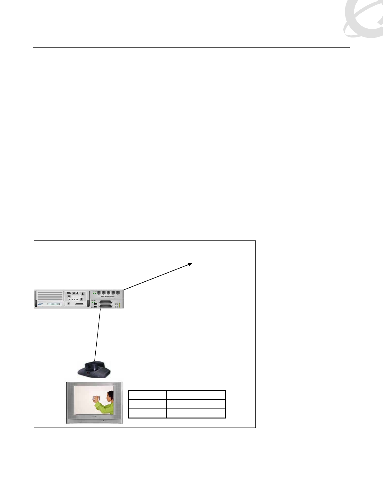
1.2 Reference Network
Pool: PRI-A
(access code 6)
Loop 601
DN: 2484
DN: 2485
Destination
Video Unit
DN: 395-1428
DN SPID
2484 248400
2485 248500
Figure 1: Reference Topology
_______________________________________________________________________________________________________________________
NORTEL External Distribution
5
Page 7

BCM Technical Configuration Guide V1.1 May, 2006
2. Programming
The following information is intended to supplement the existing suite of Nortel Business Communication
Documentations. It is intended for an informed and experienced audience familiar with programming,
administration, and maintenance of a BCM.
2.1 Before You Start
2.1.1 Pre-requisites
• Existing, and proven, PRI DID connection, with CbC Service, to the PSTN. This includes the
corresponding BCM DTM MBM and all associated programming.
• Polycom VideoStation point-to-point video conferencing system running software x.
2.1.2 Additional Information
• Available target line ; for this document, TL 241 will be used
• Available ISDN DNs ; in our example, DNs 2484 and 2485 will be used
2.2 Flow
To complete the setup of this configuration, we will begin with the installation of the BRI MBM and conclude with
the programming of the Polycom VideoStation unit.
The following setup process graphic is provided as a job aid for guidance to the novice user. It does not
supersede any instructions or methods contained in Nortel BCM documentation.
_______________________________________________________________________________________________________________________
NORTEL External Distribution
6
Page 8

BCM Technical Configuration Guide V1.1 May, 2006
• Install onto appropriate BUS & Activate
MBM
• Get Loop numbers
• Activate Loops
ISDN
DNs
Loops
Routing
Target
Line
Polycom
• Select DNs
• Assign target line
•Configure OLI
• Configure as “s” interface
• Assign DNs
• Verify PRI pool correctly programmed
• Map incoming spill
• Program DNs
• Disable H.323 & SIP
• Configure SPIDs
Figure 2: Configuration Flow
2.3 MBM
The objective of the following steps is to insert and activate the ISDN Basic Rate Interface (BRI) MBM into the
BCM.
Firstly, identify an available BUS, and set the dip switches accordingly; in this example, we are using BUS 06.
Once inserted, set the programming to “Trunk Module”.
_______________________________________________________________________________________________________________________
NORTEL External Distribution
7
Page 9

BCM Technical Configuration Guide V1.1 May, 2006
Figure 3: BRI Media Bay Module - BUS 6
With the BRI MBM in place, continue the programming by selecting Module 1 and configuring this as a “BRI-ST”
interface.
Figure 4: BRI MBM - Module 1
_______________________________________________________________________________________________________________________
NORTEL External Distribution
8
Page 10

BCM Technical Configuration Guide V1.1 May, 2006
To activate the ISDN BRI Loop, change its status to “Provisioned”.
Figure 5: BRI MBM - Status
2.4 ISDN DNs
The next steps consist of ensuring that the selected ISDN DNs have the necessary features and operating
parameters to originate and terminate calls. Note that the screen captures detail one of the two DNs that must be
programmed.
The first step is to ensure that the DNs are correctly identified as being of type ISDN. Repeat for both ISDN DNs
to be associated with the video unit.
_______________________________________________________________________________________________________________________
NORTEL External Distribution
9
Page 11

BCM Technical Configuration Guide V1.1 May, 2006
Figure 6: ISDN DNs - DN 2484
The Calling Line ID (CLID) or Outgoing Line Identification (OLI) is the key to ensuring that the far end system will
call back the originating system to complete call setup. In this case, our tests were performed on Nortel’s
corporate network, which operates on a five digit dial plan. For these purposes, the OLI was set to the BCM’s
prime DN (34190), and was padded with zeros to fill out a full 10 digit as if it was a complete public number.
Thus, in a non-PBX implementation, this field would be set to a complete 10 digit number. For example, if the
videoconferencing DN was (905)555-5200, the “Public OLI number” field should be set to 9055555200.
Repeat these steps, for both ISDN DNs to be associated with the video unit, using the appropriate 10 digit DNs
for each line.
Figure 7: ISDN DNs - Line Access (OLI)
To ensure that incoming video calls to DN 34190 are routed to the correct BCM DN, a target line needs to be
configured. In this example, TL 241 is added to the DN 2485. This is completed via the “add” button seen in the
figure below.
_______________________________________________________________________________________________________________________
NORTEL External Distribution
10
Page 12

BCM Technical Configuration Guide V1.1 May, 2006
Note that a second target line for the second B channel is not needed, and should not be configured.
Also, both DNs must be identified to the BCM as Caller ID capable sets.
Figure 8: ISDN DNs - Line Assignment
The next steps consist of giving the ISDN DNs access to the PRI network facilities. In this BCM, the PRI lines
have been assigned to the pool PRI-A; use the “add” command highlighted in the figure below.
Figure 9: ISDN DNs - Line Pool Access
_______________________________________________________________________________________________________________________
NORTEL External Distribution
11
Page 13

BCM Technical Configuration Guide V1.1 May, 2006
2.5 Loops
The physical characteristics of the BRI interfaces are defined in the following steps. Follow the scree n captures to
ensure that each programmable field is set correctly.
Figure 10: Loops
Associate both DNs to the loop.
Figure 11: Loop - Assigned DNs
2.6 Routing
Video calls will be dialed directly from the video unit, and will use the dialplan programmed into the BCM. For this
example, we have pre-determined that the PRI lines have been pooled into pool PRI-A, and that the access code
for this pool is 6. Follow the screen captures below to ensure that the routing in your system is consistent with the
customer preferences.
_______________________________________________________________________________________________________________________
NORTEL External Distribution
12
Page 14

BCM Technical Configuration Guide V1.1 May, 2006
Figure 12: Call Routing - Destination Codes
Figure 13: Call Routing - Route
2.7 Target Line
In this example, the programming of the target line allows the BCM to route any incoming calls with the Called
Number of 34190 to be routed to DN 2468.
_______________________________________________________________________________________________________________________
NORTEL External Distribution
13
Page 15

BCM Technical Configuration Guide V1.1 May, 2006
Figure 14: Target Line
Figure 15: Target Line - Received Number
2.8 Multiple Loop Setup
The previous examples detail the programming of two complete BRI loops, a total of four B channels, to the video
unit. It should be noted that additional loops can be utilized, and the programming is an extrapolation of the
information given above.
It should be noted that during the development of this document, three (384 Kbps) and four (512 Kbps) loop
configurations were setup and tested.
2.9 Polycom
The unit utilized for our testing was a VideoStation 512 running software Release 7.2 – March 10, 2002.
_______________________________________________________________________________________________________________________
NORTEL External Distribution
14
Page 16

BCM Technical Configuration Guide V1.1 May, 2006
From the Polycom Administration window visible on the video monitor, complete the setup of the system a s per
the documentation & practices provided by the manufacturer.
In addition, the following subset of setup information is provided as an example to follow. Each individual system
configuration will vary; your values will be different from these.
Admin / Network Setup:
• Call Preferences
o Select ISDN Video Calls (H.320)
o Ensure that LAN/Internet Calls (H.323) is de-selected
o Ensure that Display IP Dialing Extension is de-selected
• IMUX
o Number
Set Area Code to an appropriate value (i.e. 905)
Line1 B1: set to the extension used in the BCM, in this example it is 2484
Line1 B2: set to the extension used in the BCM, in this example it is 2485
o SPIDs
We used the following pattern “00” + BCM DN + “00”
In this example Line1 B1: 00248400
Line1 B2: 00248500
o ISDN Video (the values below were used for our testing)
Country Code: 1
Area Code: 905
Number A: 2484
Number B: 2485
ISDN Switch Protocol: NI-1
ISDN Dialing Prefix: leave blank
_______________________________________________________________________________________________________________________
NORTEL External Distribution
15
Page 17

BCM Technical Configuration Guide V1.1 May, 2006
3. Caveats
3.1 BCM Diagnostics
During the debugging phase of this project, it was observed that the diagnostic information displayed for the BRI
Loops appears to be incorrect and misleading. Unified Manager’s BRI loop diagnostic information may
indicate that they are out of service when in fact they are operational.
If you observe the conditions depicted in the screen captures below, it is recommended that you:
Complete the programming and attempt to place a video call using BCM Monitor to see if there is activity
from the video unit as it attempts to seize an outgoing line
Notify Nortel support of your observations, referencing this document
Figure 16: In-service Diagnostic Loop 601 Layer 1
3.2 PRI Trunking
If incoming video calls to the BCM are failing, verify with the Telco that the PRI Trunk has been enabled for voice
and data.
_______________________________________________________________________________________________________________________
NORTEL External Distribution
16
Page 18

BCM Technical Configuration Guide V1.1 May, 2006
Figure 17: Diagnostic Loop 601 Layer 2
_______________________________________________________________________________________________________________________
NORTEL External Distribution
17
Page 19

BCM Technical Configuration Guide V1.1 May, 2006
Contact Us:
For product support and sales information, visit the Nortel Networks website at:
http://www.nortel.com
In North America, dial toll-free 1-800-4Nortel, outside North America dial 987-288-3700.
_______________________________________________________________________________________________________________________
NORTEL External Distribution
18
 Loading...