

Page 1

Telephony Device Installation Guide
BCM50 2.0
Business Communications Manager
Document Status: Standard
Document Number: NN40020-309
Document Version: 03.01
Date: September 2006
Page 2

Copyright © 2006 Nortel Networks, All Rights Reserved
The information in this document is subject to change without notice. The statements, configurations, technical data, and
recommendations in this document are believed to be accurate and reliable, but are presented without express or implied
warranty. Users must take full responsibility for their applications of any products specified in this document. The
information in this document is proprietary to Nortel Networks.
Trademarks
Nortel, the Nortel logo, and the Globemark are trademarks of Nortel Networks.
All other trademarks and registered trademarks are the property of their respective owners.
Page 3

Contents
Chapter 1
Getting started with telephony devices . . . . . . . . . . . . . . . . . . . . . . . . . . . . . 7
About this guide . . . . . . . . . . . . . . . . . . . . . . . . . . . . . . . . . . . . . . . . . . . . . . . . . . . . . . . 7
Audience . . . . . . . . . . . . . . . . . . . . . . . . . . . . . . . . . . . . . . . . . . . . . . . . . . . . . . . . . . . . 7
About BCM50 . . . . . . . . . . . . . . . . . . . . . . . . . . . . . . . . . . . . . . . . . . . . . . . . . . . . . . . . 8
BCM50 key hardware elements . . . . . . . . . . . . . . . . . . . . . . . . . . . . . . . . . . . . . . . 8
Symbols and text conventions . . . . . . . . . . . . . . . . . . . . . . . . . . . . . . . . . . . . . . . . . . . . 9
Related publications . . . . . . . . . . . . . . . . . . . . . . . . . . . . . . . . . . . . . . . . . . . . . . . . . . 11
How to get Help . . . . . . . . . . . . . . . . . . . . . . . . . . . . . . . . . . . . . . . . . . . . . . . . . . . . . . 12
Chapter 2
Device description . . . . . . . . . . . . . . . . . . . . . . . . . . . . . . . . . . . . . . . . . . . . . 13
Analog devices . . . . . . . . . . . . . . . . . . . . . . . . . . . . . . . . . . . . . . . . . . . . . . . . . . . . . . 13
Digital devices . . . . . . . . . . . . . . . . . . . . . . . . . . . . . . . . . . . . . . . . . . . . . . . . . . . . . . . 13
Wireless devices . . . . . . . . . . . . . . . . . . . . . . . . . . . . . . . . . . . . . . . . . . . . . . . . . . . . . 14
IP devices . . . . . . . . . . . . . . . . . . . . . . . . . . . . . . . . . . . . . . . . . . . . . . . . . . . . . . . . . . 14
ISDN devices . . . . . . . . . . . . . . . . . . . . . . . . . . . . . . . . . . . . . . . . . . . . . . . . . . . . . . . . 15
3
Chapter 3
Installing an analog station media bay module . . . . . . . . . . . . . . . . . . . . . 19
Installing and configuring a media bay module . . . . . . . . . . . . . . . . . . . . . . . . . . . . . . 20
Configuring the media bay module . . . . . . . . . . . . . . . . . . . . . . . . . . . . . . . . . . . . . . . 21
Wiring the ASM . . . . . . . . . . . . . . . . . . . . . . . . . . . . . . . . . . . . . . . . . . . . . . . . . . . . . . 22
Installing analog devices . . . . . . . . . . . . . . . . . . . . . . . . . . . . . . . . . . . . . . . . . . . . . . . 22
Chapter 4
Installing the analog terminal adapter . . . . . . . . . . . . . . . . . . . . . . . . . . . . . 23
Configuration overview . . . . . . . . . . . . . . . . . . . . . . . . . . . . . . . . . . . . . . . . . . . . . . . . 23
Analog devices . . . . . . . . . . . . . . . . . . . . . . . . . . . . . . . . . . . . . . . . . . . . . . . . . . . 23
Installing the ATA2 . . . . . . . . . . . . . . . . . . . . . . . . . . . . . . . . . . . . . . . . . . . . . . . . . . . 24
Connecting the ATA2 . . . . . . . . . . . . . . . . . . . . . . . . . . . . . . . . . . . . . . . . . . . . . . 24
Mounting the ATA2 . . . . . . . . . . . . . . . . . . . . . . . . . . . . . . . . . . . . . . . . . . . . . . . . 25
Test insertion loss measurement . . . . . . . . . . . . . . . . . . . . . . . . . . . . . . . . . . . . . 25
Configuring the ATA2 . . . . . . . . . . . . . . . . . . . . . . . . . . . . . . . . . . . . . . . . . . . . . . . . . 27
Chapter 5
ISDN overview . . . . . . . . . . . . . . . . . . . . . . . . . . . . . . . . . . . . . . . . . . . . . . . . 29
ISDN fundamentals . . . . . . . . . . . . . . . . . . . . . . . . . . . . . . . . . . . . . . . . . . . . . . . . . . . 29
Analog versus ISDN . . . . . . . . . . . . . . . . . . . . . . . . . . . . . . . . . . . . . . . . . . . . . . . 29
Telephony Device Installation Guide
Page 4

4 Contents
Services and features for ISDN BRI and PRI . . . . . . . . . . . . . . . . . . . . . . . . . . . . . . . 31
ISDN hardware . . . . . . . . . . . . . . . . . . . . . . . . . . . . . . . . . . . . . . . . . . . . . . . . . . . . . . 36
ISDN standards compatibility . . . . . . . . . . . . . . . . . . . . . . . . . . . . . . . . . . . . . . . . . . . 38
Planning your ISDN network . . . . . . . . . . . . . . . . . . . . . . . . . . . . . . . . . . . . . . . . . . . . 39
Ordering ISDN PRI . . . . . . . . . . . . . . . . . . . . . . . . . . . . . . . . . . . . . . . . . . . . . . . . . . . 39
Ordering ISDN BRI . . . . . . . . . . . . . . . . . . . . . . . . . . . . . . . . . . . . . . . . . . . . . . . . . . . 39
Supported ISDN protocols . . . . . . . . . . . . . . . . . . . . . . . . . . . . . . . . . . . . . . . . . . . . . . 40
Types of ISDN service . . . . . . . . . . . . . . . . . . . . . . . . . . . . . . . . . . . . . . . . . . . . . 30
ISDN layers . . . . . . . . . . . . . . . . . . . . . . . . . . . . . . . . . . . . . . . . . . . . . . . . . . . . . . 30
ISDN bearer capability . . . . . . . . . . . . . . . . . . . . . . . . . . . . . . . . . . . . . . . . . . . . . 31
PRI services and features . . . . . . . . . . . . . . . . . . . . . . . . . . . . . . . . . . . . . . . . . . . 32
BRI services and features . . . . . . . . . . . . . . . . . . . . . . . . . . . . . . . . . . . . . . . . . . . 32
Service provider features . . . . . . . . . . . . . . . . . . . . . . . . . . . . . . . . . . . . . . . . . . . 32
Network name display . . . . . . . . . . . . . . . . . . . . . . . . . . . . . . . . . . . . . . . . . . . . . . 33
Name and number blocking . . . . . . . . . . . . . . . . . . . . . . . . . . . . . . . . . . . . . . . . . 33
Call by Call Service Selection for PRI . . . . . . . . . . . . . . . . . . . . . . . . . . . . . . . . . . 34
Emergency 911 dialing . . . . . . . . . . . . . . . . . . . . . . . . . . . . . . . . . . . . . . . . . . . . . 34
Two-way DID . . . . . . . . . . . . . . . . . . . . . . . . . . . . . . . . . . . . . . . . . . . . . . . . . . . . . 35
Dialing plan and PRI . . . . . . . . . . . . . . . . . . . . . . . . . . . . . . . . . . . . . . . . . . . . . . . 35
PRI hardware . . . . . . . . . . . . . . . . . . . . . . . . . . . . . . . . . . . . . . . . . . . . . . . . . . . . 36
BRI hardware . . . . . . . . . . . . . . . . . . . . . . . . . . . . . . . . . . . . . . . . . . . . . . . . . . . . 36
Clock source for ISDN . . . . . . . . . . . . . . . . . . . . . . . . . . . . . . . . . . . . . . . . . . . . . . 38
ISDN BRI NT1 equipment . . . . . . . . . . . . . . . . . . . . . . . . . . . . . . . . . . . . . . . . . . . 38
Chapter 6
IP telephone overview . . . . . . . . . . . . . . . . . . . . . . . . . . . . . . . . . . . . . . . . . . 41
IP telephones and VoIP trunks . . . . . . . . . . . . . . . . . . . . . . . . . . . . . . . . . . . . . . . . . . 42
Creating the IP telephony network . . . . . . . . . . . . . . . . . . . . . . . . . . . . . . . . . . . . . . . 42
Networking with BCM50 2.0 . . . . . . . . . . . . . . . . . . . . . . . . . . . . . . . . . . . . . . . . . 44
Key IP telephony concepts . . . . . . . . . . . . . . . . . . . . . . . . . . . . . . . . . . . . . . . . . . . . . 46
Chapter 7
Registering Nortel 20XX and 11XX IP telephones. . . . . . . . . . . . . . . . . . . . 49
Determining the registration process . . . . . . . . . . . . . . . . . . . . . . . . . . . . . . . . . . . . . . 49
Registering the telephone to the system . . . . . . . . . . . . . . . . . . . . . . . . . . . . . . . . 50
Configuring telephone settings . . . . . . . . . . . . . . . . . . . . . . . . . . . . . . . . . . . . . . . 50
Troubleshooting IP telephones . . . . . . . . . . . . . . . . . . . . . . . . . . . . . . . . . . . . . . . 55
Operation issues . . . . . . . . . . . . . . . . . . . . . . . . . . . . . . . . . . . . . . . . . . . . . . . . . . 56
Deregistering IP telephones . . . . . . . . . . . . . . . . . . . . . . . . . . . . . . . . . . . . . . . . . . . . 56
Chapter 8
Relocating telephones. . . . . . . . . . . . . . . . . . . . . . . . . . . . . . . . . . . . . . . . . . 59
Moving digital telephones . . . . . . . . . . . . . . . . . . . . . . . . . . . . . . . . . . . . . . . . . . . . . . 59
NN40020-309NN40020-309
Page 5

Contents 5
Keeping an IP telephone active . . . . . . . . . . . . . . . . . . . . . . . . . . . . . . . . . . . . . . . . . . 60
Moving IP telephones . . . . . . . . . . . . . . . . . . . . . . . . . . . . . . . . . . . . . . . . . . . . . . . . . 60
User card list . . . . . . . . . . . . . . . . . . . . . . . . . . . . . . . . . . . . . . . . . . . . . . . . . . . . . . . . 61
Appendix A
ADID wiring chart . . . . . . . . . . . . . . . . . . . . . . . . . . . . . . . . . . . . . . . . . . . . . . 63
Appendix B
ASM8, ASM8+, and GASM wiring chart . . . . . . . . . . . . . . . . . . . . . . . . . . . . 65
Appendix C
DSM16 and DSM32 wiring charts . . . . . . . . . . . . . . . . . . . . . . . . . . . . . . . . . 67
Appendix D
DTM wiring chart . . . . . . . . . . . . . . . . . . . . . . . . . . . . . . . . . . . . . . . . . . . . . . 69
Appendix E
BRI wiring chart . . . . . . . . . . . . . . . . . . . . . . . . . . . . . . . . . . . . . . . . . . . . . . . 71
Appendix F
BRIM wiring chart. . . . . . . . . . . . . . . . . . . . . . . . . . . . . . . . . . . . . . . . . . . . . . 73
Appendix G
G4x16 and G8x16 wiring charts . . . . . . . . . . . . . . . . . . . . . . . . . . . . . . . . . . 75
Appendix H
GATM wiring chart . . . . . . . . . . . . . . . . . . . . . . . . . . . . . . . . . . . . . . . . . . . . . 79
Telephony Device Installation Guide
Page 6

6 Contents
NN40020-309NN40020-309
Page 7

Chapter 1
Getting started with telephony devices
This section contains information on the following topics:
• “About this guide” on page 7
• “Audience” on page 7
• “About BCM50” on page 8
• “Symbols and text conventions” on page 9
• “Related publications” on page 11
• “How to get Help” on page 12
About this guide
This guide provides task-based information on how to install analog, digital, IP, and ISDN devices
running on a BCM50 system.
7
Use Element Manager, Startup Profile, and Telset Administration to configure certain BCM50
parameters.
The information in this guide explains
• installing and configuring components
• registering and relocating telephones and devices
• programming loops, configuring digital telephones
• managing system-wide call appearance (SWCA) keys
• setting up central answering positions (CAP)
Audience
This guide is intended for installers responsible for installing, configuring, and maintaining
telephony devices on BCM50 systems.
To use this guide, you must
• be an authorized BCM50 installer/administrator within your organization
• know basic Nortel BCM50 terminology
• be knowledgeable about telephony and IP networking technology
Telephony Device Installation Guide
Page 8

8 Chapter 1 Getting started with telephony devices
About BCM50
The BCM50 system provides private network and telephony management capability to small and
medium-sized businesses.
The BCM50 system
• integrates voice and data capabilities, voice over Internet protocol (VoIP) gateway functions,
and Quality of Service (QoS) data-routing features into a single telephony system
• enables you to create and provide telephony applications for use in a business environment
BCM50 key hardware elements
BCM50 includes the following key elements:
• BCM50 main unit
• BCM50 expansion unit (compatible with BCM50 main unit)
• media bay modules (MBM):
—4 x 16
—8 x 16
— ADID4
— ADID8
— ASM8, ASM8+
— BRIM
—CTM4, CTM8
— DDIM
— DSM16, DSM32
— DSM16+, DSM32+
—DTM
—FEM
— GASM
—GATM4, GATM8
BCM50 features
BCM50 supports the complete range of IP telephony features offered by existing BCM products.
NN40020-309NN40020-309
Note: You enable the following features by entering the appropriate keycodes (no
additional hardware is required)
Page 9
Chapter 1 Getting started with telephony devices 9
BCM50 applications
BCM50 Release 2.0 supports many applications provided on the existing BCM50 platform.
Note: You enable the following features by entering the appropriate keycodes (no
additional hardware is required)
• Voice Messaging for standard voice mail and auto-attendant features
• Unified Messaging, providing integrated voice mail management between voice mail and
common e-mail applications
• Fax Suite, providing support for attached analog fax devices
• voice networking features
• LAN (computer telephony engine) CTE
•VEWAN
• Interactive Voice Response (IVR)
•IP Music
• Contact Center
Symbols and text conventions
These symbols are used to Highlight critical information for the Administration Guide (N0060598)
system:
Caution: Alerts you to conditions where you can damage the equipment.
Danger: Alerts you to conditions where you can get an electrical shock.
Warning: Alerts you to conditions where you can cause the system to fail or work
improperly.
Note: A Note alerts you to important information.
Tip: Alerts you to additional information that can help you perform a task.
Telephony Device Installation Guide
Page 10

10 Chapter 1 Getting started with telephony devices
Security note: Indicates a point of system security where a default should be changed,
or where the administrator needs to make a decision about the level of security required
!
for the system.
Warning: Alerts you to ground yourself with an antistatic grounding
strap before performing the maintenance procedure.
Warning: Alerts you to remove the BCM50 main unit and expansion
unit power cords from the ac outlet before performing any maintenance
procedure.
These conventions and symbols are used to represent the Business Series Terminal display and
key pad.
Convention Example Used for
Word in a special font (shown in
the top line of the display)
Underlined word in capital letters
(shown in the bottom line of a two
line display telephone)
Dialpad buttons
Pswd:
PLAY
£
Command line prompts on display telephones.
Display option. Available on two line display
telephones
option on the display to proceed.
Buttons you press on the dialpad to select a
particular option.
. Press the button directly below the
These text conventions are used in this guide to indicate the information described:
Convention Description
bold Courier
text
Indicates command names and options and text that you need to enter.
Example: Use the
Example: Enter
info command.
show ip {alerts|routes}.
italic text Indicates book titles
plain Courier
text
Indicates command syntax and system output (for example, prompts
and system messages).
Example:
Set Trap Monitor Filters
FEATURE
HOLD
RELEASE
NN40020-309NN40020-309
Indicates that you press the button with the coordinating icon on
whichever set you are using.
Page 11

Related publications
This document refers to other related publications, which appear in the following list. To locate
specific information, you can refer to the Master Index of BCM50 2.0 Library.
Device Configuration Guide (NN40020-300)
Installation and Maintenance Guide (NN40020-302)
Telephone Features User Guide (NN40020-100)
Chapter 1 Getting started with telephony devices 11
Telephony Device Installation Guide
Page 12

12 Chapter 1 Getting started with telephony devices
How to get Help
This section explains how to get help for Nortel products and services.
Getting Help from the Nortel Web site
The best way to get technical support for Nortel products is from the Nortel Technical Support
Web site:
http://www.nortel.com/support
This site provides quick access to software, documentation, bulletins, and tools to address issues
with Nortel products. More specifically, the site enables you to:
• download software, documentation, and product bulletins
• search the Technical Support Web site and the Nortel Knowledge Base for answers to
technical issues
• sign up for automatic notification of new software and documentation for Nortel equipment
• open and manage technical support cases
Getting Help over the phone from a Nortel Solutions Center
If you don’t find the information you require on the Nortel Technical Support Web site, and have a
Nortel support contract, you can also get help over the phone from a Nortel Solutions Center.
In North America, call 1-800-4NORTEL (1-800-466-7835).
Outside North America, go to the following Web site to obtain the phone number for your region:
http://www.nortel.com/callus
Getting Help from a specialist by using an Express Routing Code
To access some Nortel Technical Solutions Centers, you can use an Express Routing Code (ERC)
to quickly route your call to a specialist in your Nortel product or service. To locate the ERC for
your product or service, go to:
http://www.nortel.com/erc
Getting Help through a Nortel distributor or reseller
If you purchased a service contract for your Nortel product from a distributor or authorized
reseller, contact the technical support staff for that distributor or reseller.
NN40020-309NN40020-309
Page 13

Chapter 2
Device description
This chapter describes the telephony devices (telephones) that BCM50 supports.
Analog devices
BCM50 supports analog telephones (single-line telephones), cordless telephones, fax machines,
answering machines, and modems (with a maximum speed of 28.8 kbit/s). You must install an
analog station media bay module (ASM8, ASM8+, and GASM) for analog devices (see Chapter 3,
“Installing an analog station media bay module). To connect a standard analog voice device or
data communication device to the BCM50 system through a digital station module, you must
install an ATA2 (see Chapter 4, “Installing the analog terminal adapter).
Digital devices
13
BCM50 supports the following digital devices:
• T7000(International only): four memory buttons, without display or indicators
• T7100: one-line display, one memory button without indicator
• T7208: one-line display, eight memory buttons with indicators
• T7316: two-line display, three display buttons, 16 memory buttons with indicators, eight
memory buttons without indicators.
The T7316 supports separate mute key and a headset key under the dial pad.
• T7316E: two-line display, three display buttons, 16 memory buttons with indicators, eight
memory buttons without indicators; handsfree, mute, and headset buttons (located under the
dial pad)
• T7406 cordless telephone system: six memory buttons with indicators and a two-line display
with three display buttons.
The T7406 provides cordless mobility in a small office environment. Each base station
supports three telephones. Function is based on the 7316 telephone. The base station connects
to a digital station media bay module on the system.
• Key Indicator Module (KIM): 24 memory buttons with indicators
• BST Doorphone: used as an intercom to control access to your building. Press the Call button
on the BST Doorphone to call one or more telephones, or to send a distinctive chime to
telephones in an assigned page zone. Place an internal call from any telephone on the system
to the BST Doorphone to set up a two-way voice call. Install a Door Opening Controller to
permit the activation of locks on doors or gates.
Telephony Device Installation Guide
Page 14

14 Chapter 2 Device description
Wireless devices
BCM50 supports the following wireless devices:
• Dect 413x series handsets: three display softkeys, four-line handset display, text messaging
• Dect 414x series handsets: three display softkeys, four-line handset display, loudspeaker
capability, text messaging
• Digital Mobility Phone 7420: three display softkeys, four-line handset display
• Digital Mobility Phone 7430: three display softkeys, four-line handset display, text
messaging
• Digital Mobility Phone 7440: three display softkeys, four-line handset display, loudspeaker
capability, text messaging
• WLAN Handsets 2210/2211/2212: Voice over IP (VoIP) technology, Push-to-Talk (enables
two-way communication with another BCM50 user)
The handsets communicate with the BCM50 system and with the WLAN IP Telephony
Manager 2245. Just like wired telephones, the wireless handsets receive calls directly, receive
transferred calls, transfer calls to other extensions, and make outside and long-distance calls
(subject to corporate restrictions). The handsets interoperates with other IP Line and IP Trunk
features and devices, such as IP Peer, and the IP Phone 20xx and IP Softphone 2050 series of
IP Phones.
IP devices
BCM50 supports the following IP devices:
• IP Phone 2001: connects through an IP link to the BCM50 system. The IP Phone 2001 has a
single-line text display with a row of display keys on the second display line. The IP Phone
2001 can be used to call through any type of BCM50 line.
• IP Phone 2002: connects through an IP link to the BCM50 system. The IP Phone 2002 has a
two-line text display with a row of display keys on the third display line, and four memory
keys with indicators. The IP Phone 2002 can be used to call through any type of BCM50 line.
• IP Phone 2004: connects through an IP link to the BCM50 system. The IP Phone 2004 has a
six-line text display with a row of display keys on the eighth display line, and six memory
keys with indicators. The IP Phone 2004 can be used to call through any type of BCM50 line.
• IP Phone 2007: connects to a LAN through an Ethernet connection. The IP Phone 2007
supports call processing features, and can work with an External Application Server to display
web-based and interactive applications on the large, color LCD touch screen.
• IP Softphone 2050: provides Voice over IP (VoIP) services using a telephony server and your
company’s local area network (LAN)
• IP Audio Conference Phone 2033: provides audio conferencing. The keypad provides many
of the set features of the basic Business Series telephones without display or memory buttons.
The audio conference phone comes with three microphones. Installation instructions are
provided with the audio conference phone.
• IP Phone 1120/1120E: graphical, high-resolution LCD display, backlit, with adjustable
contrast. It also has four user-defined feature keys and four soft keys.
NN40020-309NN40020-309
Page 15

The IP Phone 1120 brings voice and data to the desktop by connecting directly to a local area
network (LAN) though an Ethernet connection
• IP Phone 1140/1140E: graphical, high-resolution LCD display, backlit, with adjustable
contrast. It also has six user defined feature keys and four soft keys
The IP Phone 1140 brings voice and data to the desktop by connecting directly to a LAN
through an Ethernet connection.
• IP Key Expansion Module (KEM): 24 programmable keys (with labels) for IP Phone 2002
or 2004 models; maximum of four IP KEMs for one phone
ISDN devices
Refer to Chapter 5, “ISDN overview for information on ISDN devices (hardware).
Table 1 is a matrix of telephony devices and the BCM releases with which they are compatible.
Table 1 also shows what media bay module (MBM) is needed to support each device.
Table 1 Telephony devices release compatibility matrix
Chapter 2 Device description 15
Device BCM 3.5 BCM 3.6 BCM 3.7 BCM 4.0
T7000 (EU only) XXXXXXDSM
T7100 XXXXXXDSM
T7208 XXXXXXDSM
T7316 XXXXXXDSM
T7316E XXXXXXDSM
T7406 (North America only)XXXXXXDSM
T 24 KIM XXXXXXDSM
BST Doorphone XXXX
Dect 413x
Dect 414x XX XDSM
Digital Mobility Phone 7420
Digital Mobility Phone 7430
Digital Mobility Phone 7440
IP Phone 2001
IP Phone 2002 XXXXXX
IP Phone 2004 XXXXXX
IP Phone 2007 XX X
IP Phone 1110 X X
IP Phone 1120E X X
IP Phone 1140E X X
IP Softphone 2050 XXXXXX
XXXXX
XX XDSM
X XDSM
X XDSM
BCM50
1.0
BCM50
2.0
XDSM
XDSM
MBM
Telephony Device Installation Guide
Page 16

16 Chapter 2 Device description
Table 1 Telephony devices release compatibility matrix
Device BCM 3.5 BCM 3.6 BCM 3.7 BCM 4.0
IP Audio Conference Phone 2033 X X
IP KEM X X
WLAN 2210 Handset XX X
WLAN 2211 Handset XX X
WLAN 2212 Handset X X
BCM50
1.0
BCM50
2.0
Table 2 shows the types of lines supported by different MBMs and the number of lines those
MBMs support.
Table 2 MBM trunk requirements
Type of lines Type of MBM Number of lines per MBM
T1 digital digital trunk MBM (DTM) 24
PRI digital lines (NA) DTM 23
E1 digital lines DTM 30
PRI digital lines (EMEA) DTM 30
Analog lines caller ID trunk module
4(CTM4) (North American
systems only)
Analog lines CTM8 (North American
systems only)
Analog lines global analog trunk module 4
(GATM4)
Analog lines GATM8 8
Analog lines 4x16 combination MBM
(North American systems
only)
Analog lines ADID 4 4
Analog lines ADID 8 8
BRI ISDN lines BRIM S/T 4 ISDN loops (to a maximum of 8 lines)
Integrated BRI lines BRIM S/T 2 ports (replace 4 analog lines on the RJ-21
4
8
4
4 (also requires a full DS30 channel for the DNs)
telephony connector)
MBM
Table 3 MBM station requirements (Sheet 1 of 2)
Type of extension Type of MBM Number of extensions per MBM
Digital extensions DSM16/DSM16+ 16
Digital extensions DSM32/DSM32+ 32
Digital extensions 4x16 16
Analog extensions ASM8 8
NN40020-309NN40020-309
Page 17

Chapter 2 Device description 17
Table 3 MBM station requirements (Sheet 2 of 2)
Type of extension Type of MBM Number of extensions per MBM
Analog extensions GASM8 8
Cordless handsets (DECT) (selected
profiles only)
Digital extensions are for digital or IP telephones. You do not need to include IP telephones when you calculate the
number of required DSM MBMs.
DSM 32
Telephony Device Installation Guide
Page 18

18 Chapter 2 Device description
NN40020-309NN40020-309
Page 19

Chapter 3
Installing an analog station media bay module
You can connect a a maximum of eight analog telecommunication devices to the analog station
media bay modules (ASM8, ASM8+, and GASM). These devices are standard analog telephones,
cordless telephones, fax machines, answering machines, or modems. The maximum speed for a
modem connection is 28.8 kbit/s.
The ASM8 is available in North America only; the ASM8+ and GASM8 are available in North
America, the United Kingdom, Australia, and Poland.
In addition to ASM8 features, the ASM8+ and GASM offer the following features:
• Visual Message Waiting Indicator (VMWI)—LED indicates to the end user that a message is
waiting
• disconnect supervision (Open Switch Interval [OSI] according to EIA/TIA 464)—indicates to
the attached device, in an established communication, that the connected device must release
the call
19
Note: When disconnect happens from the central office (CO), the ASM8+
provides an OSI to the off-hook station of 850 ms (TIA/EIA 464 section
5.4.10.2.4; minimum is 600 ms) as a disconnect signal. If the station remains
on-hook after the disconnect signal, the ASM8+ disconnects the station equipment
from the network without returning a tone to it (TIA/EIA 464 section
5.4.10.2.5[1]). After the station equipment goes on-hook, the ASM8+ station
interface is restored to on-hook (idle).
You must ensure that the device, application, or interface card connected to an
ASM8+ station interface conform to these on-hook and off-hook conditions.
• caller ID—provides the name, phone number, and other information about the caller to the end
user at the start of the call
• firmware downloading capability—allows the system to upgrade the ASM8+ and GASM
firmware at customer sites
• enhanced ringing capability—ASM8+ and GASM provide a ringing voltage of two REN/65 V
rms per port.
• GASM8—designated as an on-premise station (OPS) port
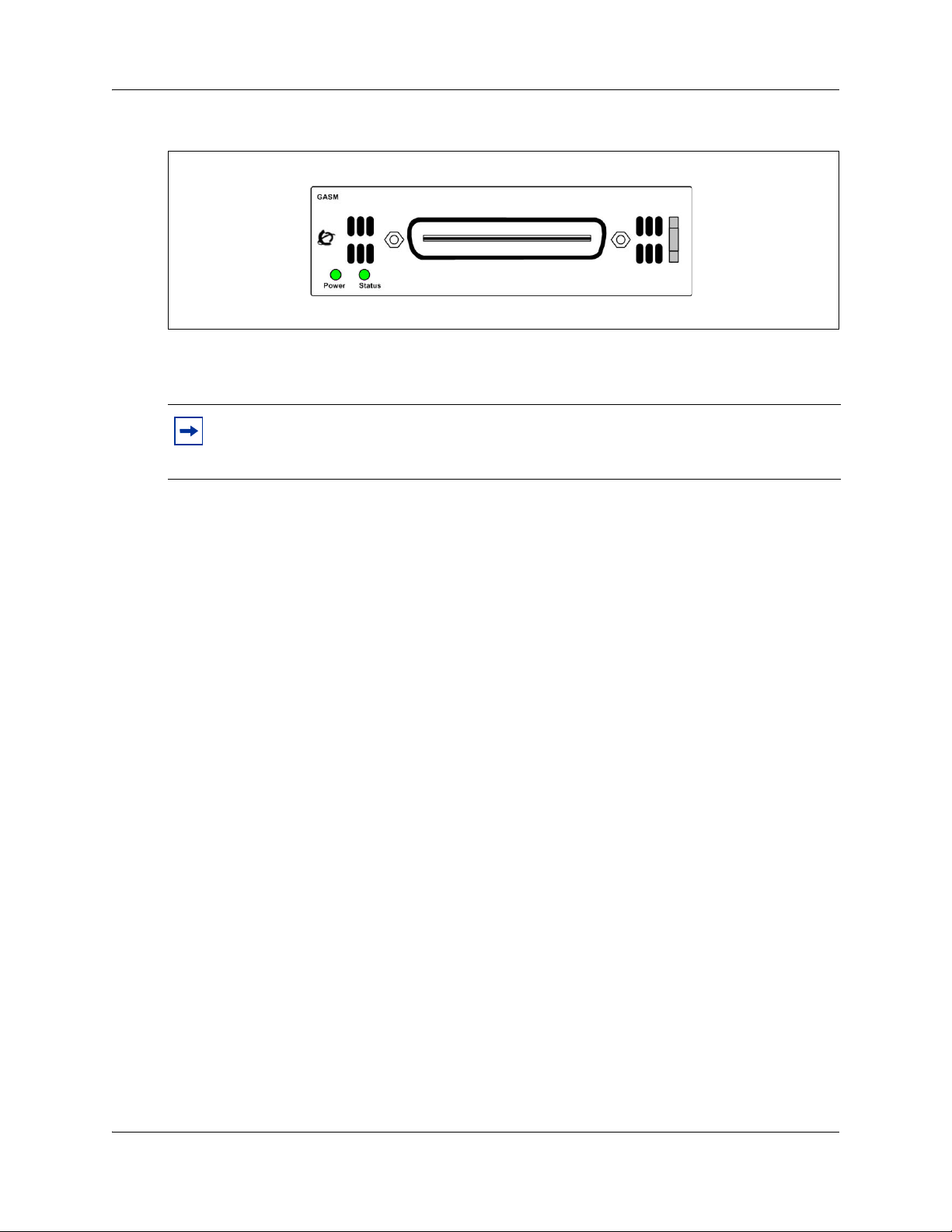
The ASM8, ASM8+, and GASM each have one RJ-21 connector on the faceplate. Figure 1 on
page 20 shows the GASM faceplate.
Telephony Device Installation Guide
Page 20
20 Chapter 3 Installing an analog station media bay module
Figure 1 GASM faceplate LEDs and connectors
The ringer equivalency number (REN) per port for ASM8 is 1; the REN for ASM8+ and GASM
is 2.
Note: The termination of the analog interface can consist of any combination of devices,
subject only to the requirement that the sum of the RENs of all the devices does not exceed
the REN of the interface to which the device is connected.
Refer to the following sections for information on installing and configuring an ASM:
• “Installing and configuring a media bay module” on page 20
• “Configuring the media bay module” on page 21
• “Wiring the ASM” on page 22
• “Installing analog devices” on page 22
For more detailed information on installing the BCM50 system and related components, refer to
Installation and Maintenance Guide (NN40020-302).
Installing and configuring a media bay module
You can install media bay modules (MBM) in BCM50 main units and expansion units, depending
on your system requirements.
The primary tasks to install an MBM are
• selecting an MBM for your system
• assigning DS30 resources
• setting MBM dip switches
• installing an MBM
For more detailed information on installing an MBM, refer to Installation and Maintenance Guide
(NN40020-302).
NN40020-309NN40020-309
Page 21

Chapter 3 Installing an analog station media bay module 21
Configuring the media bay module
For information on installing a media bay module (MBM) and setting the dip switches, refer to the
Installation and Maintenance Guide (NN40020-302).
To configure the MBM
1 Open Element Manager and connect to your BCM50 system.
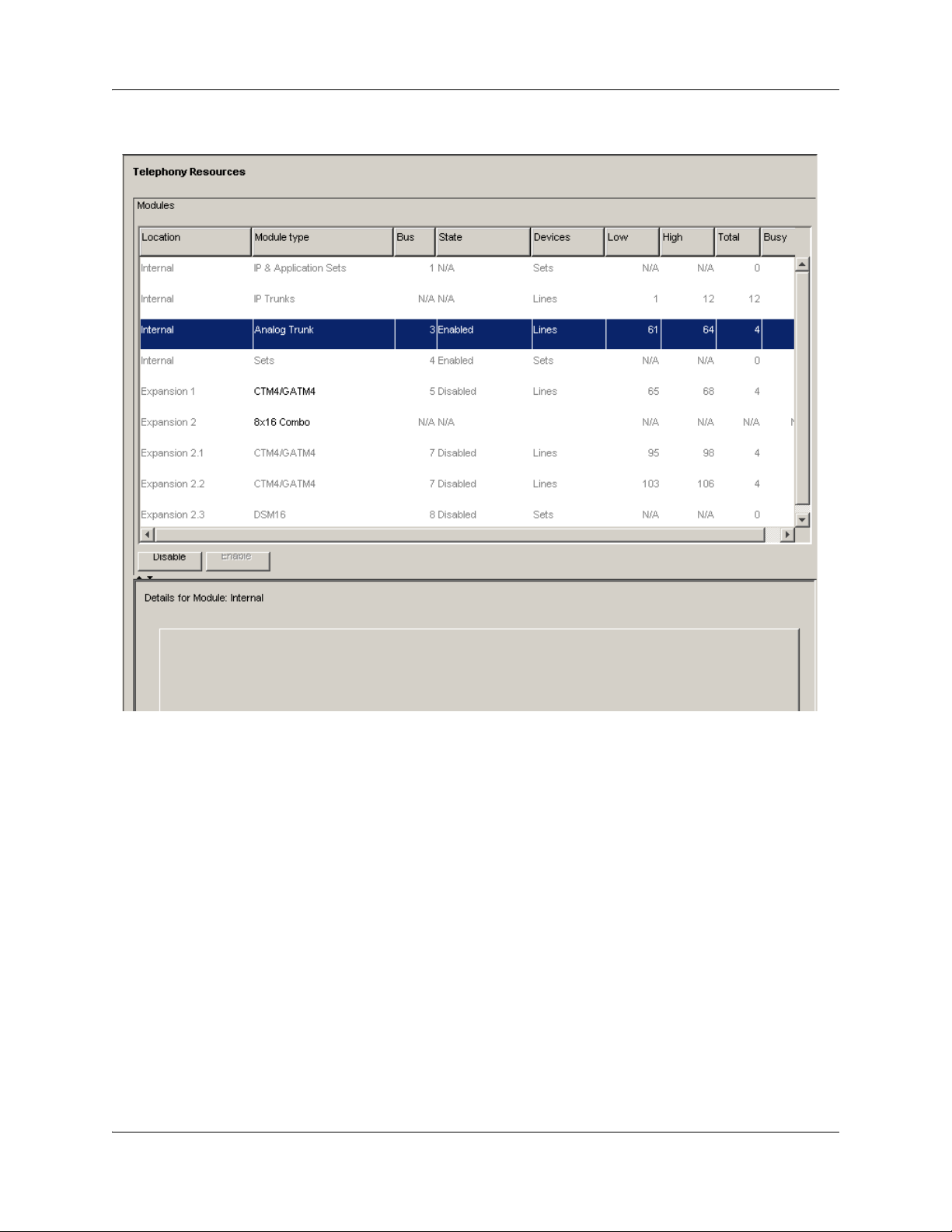
2 Click Configuration > Resources > Telephony Resources.
The Telephony Resources panel appears (see Figure 27).
3 In the Modules table, select the location of the MBM that you want to configure.
4 Double-click the Programmed type field to display the drop-down list.
5 Select the type of MBM that you installed in that location.
6 Click Enable.
7 Repeat steps 4 to 7 to enable each MBM in your system.
You can set other parameters for the MBMs depending on the type of MBM you installed.
Telephony Device Installation Guide
Page 22
22 Chapter 3 Installing an analog station media bay module
Figure 2 Telephony Resources panel
Wiring the ASM
An experienced installer can wire the ASM for your system using the wiring chart, for more
information refer to the “ASM8, ASM8+, and GASM wiring chart” on page 65.
Installing analog devices
After the ASM is correctly wired, you can connect your analog devices.
Documentation describing how to install your analog devices and how to use their features, is
supplied with each piece of equipment.
NN40020-309NN40020-309
Page 23
Chapter 4
Installing the analog terminal adapter
This chapter provides installation instructions for the analog terminal adapter 2 (ATA2) or ATA.
The ATA2 connects a standard analog voice device or data communication device to the BCM50
system through a digital station module. Examples of analog voice devices are analog telephones
and answering machines. Examples of analog data communication devices are modems and fax
machines.
The ATA2 provides on-premise service only (protected plan wiring only).
Refer to the following topics for information on installing an ATA2:
• “Configuration overview” on page 23
• “Installing the ATA2” on page 24
• “Configuring the ATA2” on page 27
23
Configuration overview
The following sections describe environment configurations for connecting analog and data
devices to the main unit using an ATA2:
• “Analog devices” on page 23
Analog devices
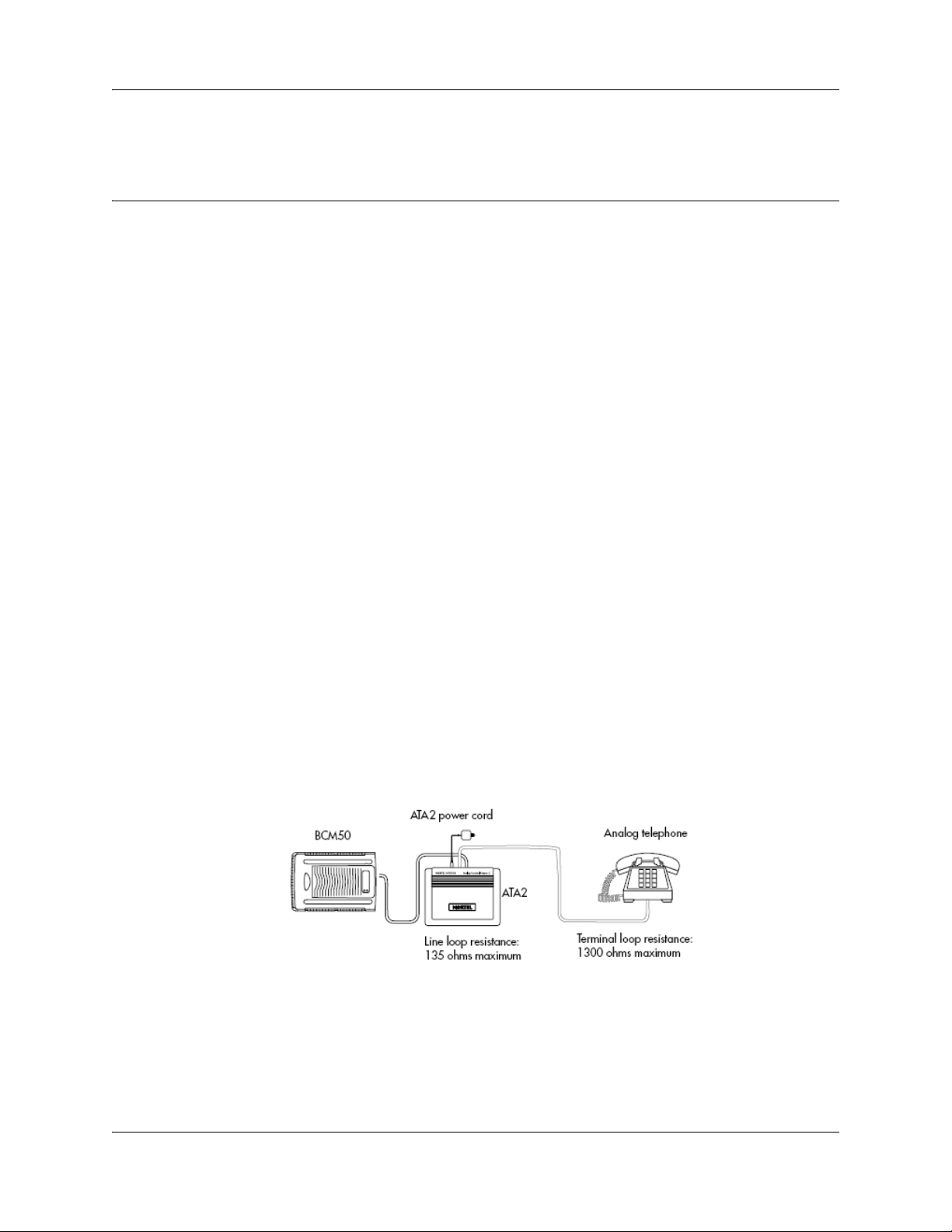
Figure 3 on page 23 shows an installation overview for connecting an analog device or analog data
device through an ATA2 to the BCM50 main unit.
Figure 3 Analog device installation overview
Telephony Device Installation Guide
Page 24
24 Chapter 4 Installing the analog terminal adapter
Installing the ATA2
The following sections provide information on installing the ATA2:
• “Connecting the ATA2” on page 24
• “Mounting the ATA2” on page 25
• “Test insertion loss measurement” on page 25
Connecting the ATA2
After the correct environment has been set up, connect the BCM50 system and the analog device
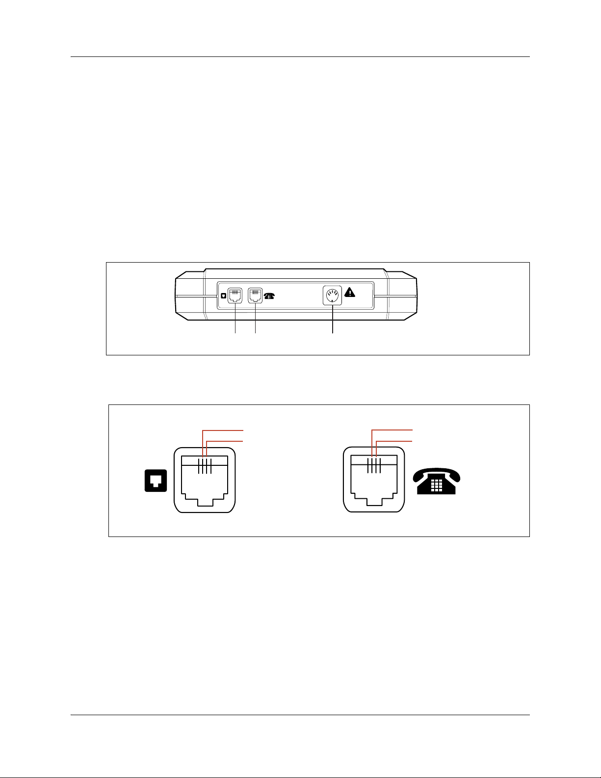
to the ATA2 and then connect the power (see Figure 4).
Figure 4 ATA 2 top view
24 V ~
0.006 A
=
Terminal jackLine jack Power supply connector receptacle
Figure 5 shows the pin-outs for the connection cables.
Figure 5 ATA2 pin-outs
Line jack
TCM*
TCM*
* The TCM input is not polarity sensitive.
Terminal jack
Ring (B-Lead)
Tip (A-Lead)
To connect the ATA2
1 Connect one end of a line cord to the ATA2 terminal jack.
2 Connect the other end of the line cord to your telephone, modem, or fax machine.
3 Connect one end of a second line cord to the ATA2 line jack.
4 Connect the other end of the line cord to an available station port on the BCM50 system.
5 For a 120-V or 230-V system, plug the DIN connector of the power supply cord into the power
supply connector receptacle.
NN40020-309NN40020-309
Page 25
Chapter 4 Installing the analog terminal adapter 25
6 Plug the adapter into a standard ac outlet.
Caution: In North America, the ATA2 must be powered from a Class 2 power source that
is UL- and CSA-approved.
In Europe, the ATA2 must be powered from a Class II power source that is CE-marked.
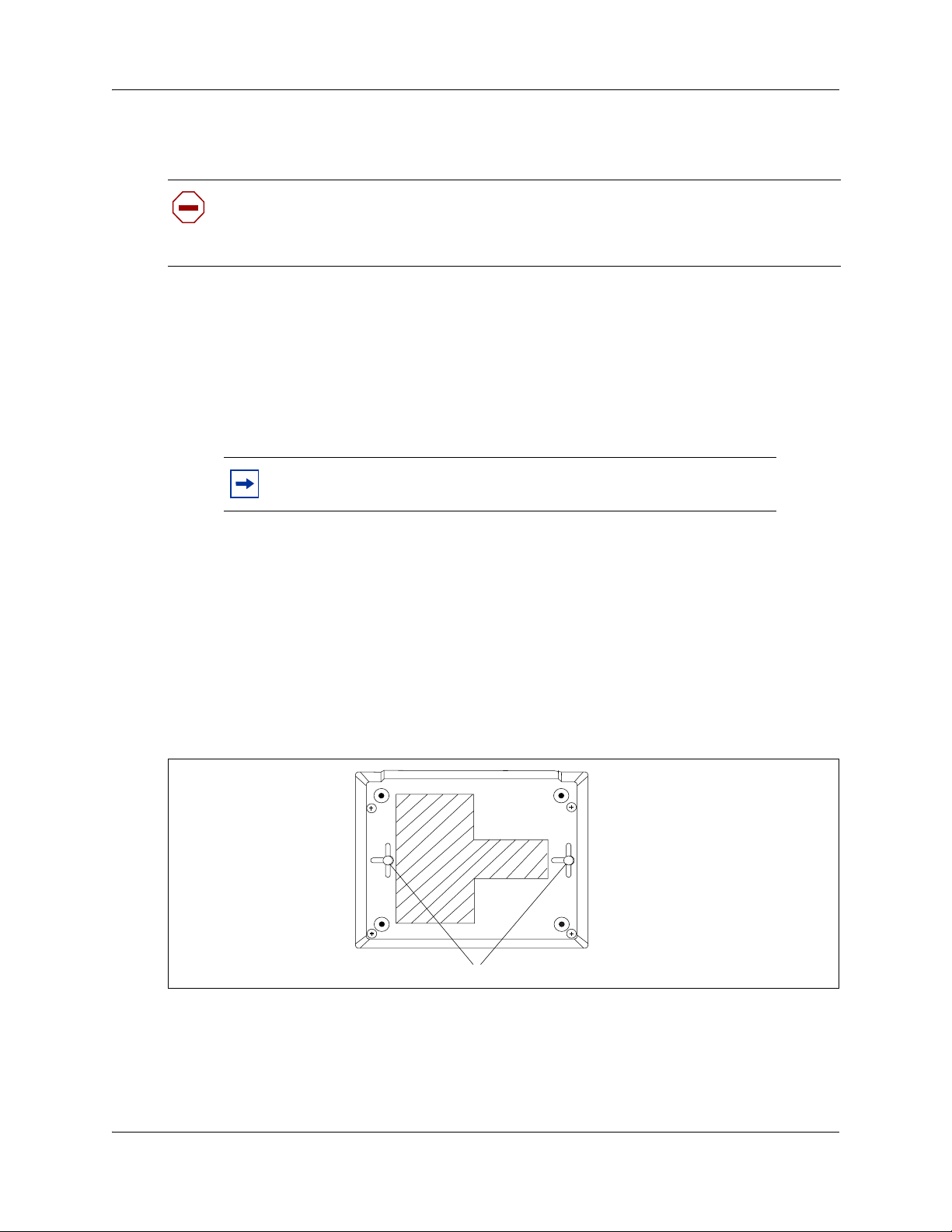
Mounting the ATA2
After you have correctly connected the ATA2, you can mount the unit on a wall.
To mount the ATA2 on a wall
1 Select a location for the ATA2 near the BCM50 main unit.
Note: If you are using 0.5 mm wire (24 AWG), select a location within
800 m (2600 ft.) of the BCM50 main unit.
2 Allow 12.5 cm (5 in.) clearance for the line jack, terminal jack, and power supply connector.
3 Screw two 4-mm (#8) screws into the wall, 130 mm (5-1/4 in.) away from each other. Leave
6 mm (1/4 in.) of the two screws showing.
4 Align the slots at the back of the ATA2 unit over the screws.
5 Push the unit against the wall.
The line jack, terminal jack, and power supply connector must be at the top of the ATA2 (see
Figure 6).
Figure 6 ATA 2 back v i e w
Mounting keyhole slots
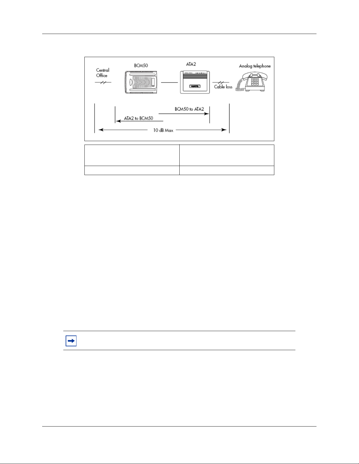
Test insertion loss measurement
The maximum loss for and ATA2-to-Central Office (CO) configuration must not exceed 10 dB
(see Figure 7 on page 26).
Telephony Device Installation Guide
Page 26
26 Chapter 4 Installing the analog terminal adapter
Figure 7 Insertion loss from the CO to the analog telephone
Longitudinal balance to ground 50 dB
Overload level 3 dB
Measure the total insertion loss between the CO and analog device by using standard dial-up test
lines with a transmission test set (for example, Hewlett-Packard 4935A Transmission Test Set).
60 to 4,000 Hz
With IEEE 455-1976 test
To measure the insertion loss from the CO to the analog device
1 Establish a connection to the 1 mW, 1 kHz, CO service line with an analog telephone attached
to the ATA2.
2 Ensure that the analog port terminates correctly in 600 ohms:
• Replace the analog telephone with the test set.
• Use RECEIVE/600 OHM/HOLD mode on the test set.
3 Ensure that the test set connects in parallel to the service line before removing the analog
telephone, or the line drops.
4 Remove the single-line telephone.
5 Measure the 1-kHz tone at the far end of the analog port, which is where the analog loop ends
and where the analog device connects.
Note: The tone must be greater than - 10 dB (for example, - 9 dB is acceptable).
NN40020-309NN40020-309
Page 27

Chapter 4 Installing the analog terminal adapter 27
To measure the insertion loss from the analog device to the CO
1 Establish a connection to a silent termination on the CO service line with an analog telephone
attached to the ATA2.
2 Make sure the analog port terminates correctly in 600 ohms:
• Replace the analog telephone with the test set.
• Use TRANSMIT/600 OHM/HOLD mode on the test set.
3 Make sure the test set connects in parallel to the service line before removing the analog
telephone or the line drops.
4 Remove the analog telephone.
5 Introduce a 1-kHz tone into the analog line at - 10 dBm, and measure the level at the CO
exchange.
Note: The difference in levels is the transmit loss and must be less than 10 dB
(for example, 9 dB is acceptable).
Configuring the ATA2
Configure the ATA2 using Element Manager or Telset Administration. For detailed configuration
information, refer to the BCM50 Device Configuration Guide (N0027146).
Telephony Device Installation Guide
Page 28

28 Chapter 4 Installing the analog terminal adapter
NN40020-309NN40020-309
Page 29

Chapter 5
ISDN overview
The following provides some general information about using ISDN lines on your BCM50 system.
Detailed information about ISDN is widely available through the internet. Your service provider
can also provide you with specific information to help you understand what suits your
requirements.
Refer to the following topics for information:
• "ISDN fundamentals"
• “Services and features for ISDN BRI and PRI” on page 31
• “ISDN hardware” on page 36
• “ISDN standards compatibility” on page 38
• “Planning your ISDN network” on page 39
• “Supported ISDN protocols” on page 40
29
ISDN fundamentals
Integrated Services Digital Network (ISDN) technology provides a fast, accurate and reliable
means of sending and receiving voice, data, images, text, and other information through the
telecom network.
ISDN uses existing analog telephone wires and multiplex it into separate digital channels which
increases bandwidth.
ISDN uses a single transport to carry multiple information types. What once required separate
networks for voice, data, images, or video conferencing is now combined onto one common
high-speed transport.
Refer to the following topics:
• “Types of ISDN service” on page 30
• “ISDN layers” on page 30
• “ISDN bearer capability” on page 31
Analog versus ISDN
ISDN offers significantly higher bandwidth and speed than analog transmission because of its
end-to-end digital connectivity on all transmission circuits. Being digital allows ISDN lines to
provide better quality signaling than analog POTS lines, and ISDN out-of band data channel
signaling offers faster call set up and tear down.
While an analog line carries only a single transmission at a time, an ISDN line can carry one or
more voice, data, fax, and video transmissions simultaneously.
Telephony Device Installation Guide
Page 30

30 Chapter 5 ISDN overview
An analog modem operating at 14.4K takes about 4.5 minutes to transfer a 1MB data file and a
28.8K modem takes about half that time. Using one channel of an ISDN line, the transfer time is
reduced to only 1 minute and if two ISDN channels are used, transfer time is just 30 seconds.
When transmitting data, the connect time for an average ISDN call is about three seconds per call,
compared to about 21 seconds for the average analog modem call.
Types of ISDN service
Two types of ISDN services (lines) are available: Basic Rate Interface (BRI) and Primary Rate
Interface (PRI). Each line is made up of separate channels known as B and D channels which
transmit information simultaneously.
• BRI is known as 2B+D because it consists of two B-channels and one D-channel.
• PRI is known as 23B+D(in North America) or as 30B+D (in Europe). In North America,
23B+D consists of 23 B-channels and one D-channel (T1 carrier). In Europe, 30B+D consists
of 30 B-channels and one D-channel (E1 carrier).
B-channels: B-channels are the bearer channel and are used to carry voice or data information and
have speeds of 64 kb/s. Since each ISDN link (BRI or PRI) has more than one B-channel, a user
can perform more than one transmission at the same time, using a single ISDN link.
D-channels: The standard signaling protocol is transmitted over a dedicated data channel called
the D-channel. The D-channel carries call setup and feature activation information to the
destination and has speeds of 16 kb/s (BRI) and 64 kb/s PRI. Data information consists of control
and signal information and for BRI only, packet-switched data such as credit card verification.
ISDN layers
ISDN layers refer to the standards established to guide the manufacturers of ISDN equipment and
are based on the OSI (Open Systems Interconnection) model. The layers include both physical
connections, such as wiring, and logical connections, which are programmed in computer
software.
When equipment is designed to the ISDN standard for one of the layers, it works with equipment
for the layers above and below it. There are three layers at work in ISDN for BCM50. To support
ISDN service, all three layers must be working properly.
• Layer 1: A physical connection that supports fundamental signaling passed between the ISDN
network (your service provider) and the BCM50 system. When the LED on a BRI S/T Media
Bay Module configured as BRI is lit, your layer 1 is functioning.
• Layer 2: A logical connection between the central office or the far end and the BCM50 system.
Without Layer 2, call processing is not possible.
NN40020-309NN40020-309
Page 31

Chapter 5 ISDN overview 31
• Layer 3: Also a logical connection between the ISDN network (your service provider) and the
BCM50 system. For BRI lines, layer 3 is where call processing and service profile identifier
(SPID) information is exchanged. This controls which central office services are available to
the connection. For example, a network connection can be programmed to carry data calls.
Note: Throughout this chapter, references are made to Service profile
identifiers (SPIDs). SPIDs are a part of the BRI National ISDN standard.
SPIDs are not used in the ETSI BRI standard or on PRI.
These three layers are important when you are installing, maintaining, and troubleshooting an
ISDN system.
ISDN bearer capability
Bearer capability describes the transmission standard used by the BRI or PRI line so that it can
work within a larger ISDN hardware and software network.
The bearer capability for BRI and PRI is voice/speech, 3.1 kHz audio (fax), and data (unrestricted
64 kb/s, restricted 64 kb/s, or 56 kb/s).
Services and features for ISDN BRI and PRI
As part of an ISDN digital network, your system supports enhanced capabilities and features,
including:
• faster call set up and tear down
• high quality voice transmission
• dial-up Internet and local area network (LAN) access
• video transmission
•network name display
• name and number blocking (PRI, BRI and analog)
• access to public protocols
Refer to the following for additional information on features and services:
• “Network name display” on page 33
• “Name and number blocking” on page 33
• “Call by Call Service Selection for PRI” on page 34
• “Emergency 911 dialing” on page 34
• “Two-way DID” on page 35
• “Dialing plan and PRI” on page 35
Telephony Device Installation Guide
Page 32

32 Chapter 5 ISDN overview
PRI services and features
The services and features provided over PRI lines include:
• Call-by-call service selection (NI protocol)
• Emergency 911 dialing, internal extension number transmission
• access to Meridian 1 private networking (SL-1 protocol)
BRI services and features
The services and features provided over BRI lines include:
• data transmission at speeds up to 128 kb/s per loop (depending on the bandwidth supported by
your service provider)
• shared digital lines for voice and data ISDN terminal equipment
BCM50 Basic Rate Interface (BRI) also support D-channel packet service between a network and
terminal connection. This allows you to add applications such as point-of-sale terminals (POSTA)
without additional network connections. Connecting a POSTA allows transaction terminals
(devices where you swipe credit or debit cards) to transmit information using the D channel of the
BRI line, while the B channels of the BRI line remain available for voice and data calls. A special
adapter links transaction equipment, such as cash registers, credit card verification rigs, and
point-of-sale terminals, to the X.25 network, which is a data communications network designed to
transmit information in the form of small data packets.
To support the D-packet service, your ISDN network and financial institution must be equipped
with a D-packet handler. To convert the protocol used by the transaction equipment to the X.25
protocol, your ISDN network must also be equipped with an integrated X.25 PAD which works
with the following versions of X.25: Datapac 32011, CCITT, T3POS, ITT and API. The ISDN
service package you order must include D-packet service (for example, Package P in the United
States; Microlink™ with D-channel in Canada).
Your service provider supplies a Terminal Endpoint Identifier (TEI) and DN to support D-packet
service. The TEI is a number between 00 and 63 (in Canada, the default range is 21-63). Your
service provider may also supply you with a DN to program your D-packet device. The DN for
D-packet service becomes part of the dialing string used by the D-packet to call the packet handler.
Service provider features
BCM50 supports the following ISDN services and features offered by ISDN service providers:
• D-channel packet service (BRI only) to support devices such as transaction terminals.
Transaction terminals are used to swipe credit or debit cards and transmit the information to a
financial institution in data packets.
• Calling number identification (appears on both BCM50 sets and ISDN terminal equipment
with the capability to show the information).
• Multiline hunt or DN hunting which switches a call to another ISDN line if the line usually
used by the Network DN is busy (for BRI only).
NN40020-309NN40020-309
Page 33

Chapter 5 ISDN overview 33
• Subaddressing of terminal equipment (TE) on the same BRI loop. However, terminal
equipment which supports sub-addressing is not commonly available in North America (for
BRI only).
Transmission of B-channel packet data using nailed up trunks is not supported by BCM50.
Contact your ISDN service provider for more information about these services and features. For
more information about ordering ISDN service in North America, see “Ordering ISDN PRI” on
page 39 and “Ordering ISDN BRI” on page 39.
The terminal equipment connected to the BCM50 system can use some feature codes supported by
the ISDN service provider.
Network name display
This feature allows ISDN to deliver the Name information of the users to those who are involved
in a call that is on a public or private network.
Your BCM50 system displays the name of an incoming call when it is available from the service
provider. If the Calling Party Name has the status of private, it appears as
is how the service provider has indicated that it mus appear. If the Calling Party Name is
unavailable it can appear as
Unknown name.
Private name, if that
Your system can display the name of the called party on an outgoing call, if it is provided by your
service provider. Your system sends the Business Name concatenated with the set name on an
outgoing call but only after the Business Name has been programmed.
The available features include:
• Receiving Connected Name
• Receiving Calling Name
• Receiving Redirected Name
• Sending Connected Name
• Sending Calling Party Name
Consult your customer service representative to determine which of these features is compatible
with your service provider.
Name and number blocking
When activated, use FEATURE 819 to block the outgoing name or number (or both) for each call.
Name and number blocking can be used with a BCM50 set.
Note: Name and number blocking is only available in North America.
Consult your customer service representative to determine whether or not this feature is
compatible with your provider.
Telephony Device Installation Guide
Page 34

34 Chapter 5 ISDN overview
Call by Call Service Selection for PRI
PRI lines can be dynamically allocated to different service types with the Call by Call feature. PRI
lines do not have to be pre-allocated to a given service type. Outgoing calls are routed through a
dedicated PRI Pool and the calls can be routed based on various schedules.
Note: Call by Call Service Selection for PRI is only available in North
America.
The service types that may be available, depending on your service provider are
• Public: Public service calls connect your BCM50 set with a Central Office (CO). DID and
DOD calls are supported.
• Private: Private service calls connect your BCM50 set with a Virtual Private Network. DID and
DOD calls are supported. A private dialing plan may be used.
• TIE: TIE services are private incoming and outgoing services that connect Private Branch
Exchanges (PBX) such as BCM50.
• FX (Foreign Exchange): FX service calls logically connect your BCM50 telephone to a remote
CO. It provides the equivalent of local service at the distant exchange.
• OUTWATS: OUTWATS is for outgoing calls. This allows you to originate calls to telephones
in a specific geographical area called a zone or band. Typically a flat monthly fee is charged
for this service.
• Inwats: Inwats is a type of long distance service which allows you to receive calls originating
within specified areas without a charge to the caller. A toll-free number is assigned to allow for
reversed billing.
Consult your customer service representative to determine whether or not this feature is
compatible with your provider.
Emergency 911 dialing
The ISDN PRI feature is capable of transmitting the telephone number and internal extension
number of a calling station dialing 911 to the Public Switched Telephone Network (PSTN). State
and local requirements for support of Emergency 911 dialing service by Customer Premises
Equipment vary. Consult your local telecommunications service provider regarding compliance
with applicable laws and regulations. For most installations the following configuration rules
should be followed, unless local regulations require a modification.
Note: Emergency 911 dialing is only available in North America.
• All PSTN connections must be over PRI.
• In order for all sets to be reached from a Public Safety Answering Position (PSAP), the system
must be configured for DID access to all sets. In order to reduce confusion, the dial digits for
each set should be configured to correspond to the set extension number.
NN40020-309NN40020-309
Page 35

Chapter 5 ISDN overview 35
• The OLI digits for each set should be identical to the DID dialed digits for the set.
• The routing table should route 911 to a PRI line pool.
• If attendant notification is required, the routing table must be set up for all 911 calls to use a
dedicated line which has an appearance on the attendant console.
• The actual digit string 911 is not hard-coded into the system. More than one emergency
number can be supported.
If transmission of internal extension numbers is not required or desired, then it is recommended
that the person in charge of the system maintain a site map or location directory that allows
emergency personnel to rapidly locate a BCM50 set given its DID number. This list should be kept
up to date and readily available.
IP telephony note: Ensure that you do not apply a 911 route to an IP telephone that is off the
premises where the PSAP is connected to the system.
Two-way DID
With PRI the same lines can be used for receiving direct inward dialing (DID) and for making
direct outward dialing (DOD) calls.
The dialing plan configured by your customer service representative determines how calls are
routed. Consult your customer service representative to determine whether or not this feature is
compatible with your service provider.
Note: For information on adding integrated lines on an integrated router,
refer to the integrated router documentation.
Dialing plan and PRI
The Dialing Plan supports PRI connectivity to public and private networks. The dialing plan is a
collection of features responsible for processing and routing incoming and outgoing calls. All PRI
calls must go through a dialing plan.
Notes about the dialing plan:
• allows incoming calls to be routed to sets based on service type and digits received
• provides the ability to map user-dialed digits to a service type on a Call by Call basis
• allows long distance carrier selection through user-dialed Carrier Access Codes
Consult your customer service representative to determine how your dialing plan is configured.
Telephony Device Installation Guide
Page 36

36 Chapter 5 ISDN overview
ISDN hardware
To support connections to an ISDN network and ISDN terminal equipment, your BCM50 must be
equipped with a BRI S/T Media Bay Module (BRIM) or a Digital Trunk Media Bay Module
(DTM) card configured for PRI. The digital BRI ISDN lines are connected to the BCM50b,
BCM50ba, and BCM50be main units through the BRI ports (RJ-45) on the front of the main units.
The following describes the hardware:
• "PRI hardware"
• "BRI hardware"
Note: For information on adding integrated lines on an integrated router,
refer to the integrated router documentation.
PRI hardware
The Digital Trunk Media Bay Module (DTM) is configured for PRI. In most PRI network
configurations, you need one DTM configured as PRI to act as the primary clock reference. The
only time when you cannot have a DTM designated as the PRI primary clock reference is in a
network where your BCM50 system is connected back-to-back with another switch using a PRI
link. If the other switch is loop-timed to your BCM50 system, your DTM (PRI) can be designated
as a timing master.
If your BCM50 has more than one DTM configured as PRI, you must assign the first DTM as the
primary reference, the second DTM as the secondary reference.
If the system has a BRI module, it should be set as the timing master when a DTM in the same
network is defined as the primary reference.
BRI hardware
The loops on the BRI module can be programmed to support either network or terminal
connections. This allows you to customize your arrangement of lines, voice terminals, data
terminals and other ISDN equipment. This section describes some basic hardware configurations
for network and terminal connections for each loop type.
A BRI module provides four loops. Each loop can be individually programmed as one of the
following:
• an S reference point connection (S loop) to ISDN terminal equipment (TE)
• a T reference point connection (T loop) to an ISDN network using an external NT1
You can add integrated BRI lines on the BCM50a, BCM50e, and BCM50ae main units.
S Reference Point
The S reference point connection provides either a point-to-point or point-to-multipoint digital
connection between BCM50 and ISDN terminal equipment (TE) that uses an S interface. Refer to
Figure 8.
NN40020-309NN40020-309
Page 37

S loops support up to seven ISDN DNs, which identify TE to the BCM50 system.
In
sp
ec
t F
O
R
W
A
RD
C
allers
M
X
P
In
sp
e
c
t F
O
R
W
A
R
D
C
a
llers
M
X
P
In
sp
ect F
O
R
W
A
R
D
C
allers
M
X
P
Figure 8 S reference point
BCM50
point-to-point
s
s
ISDN TE
(with terminating resistors)
In
sp
e
c
t F
O
R
W
A
R
D
Ca
lle
r
s
M
X
P
In
sp
ect F
O
R
W
A
R
D
C
allers
M
X
P
ISDN TE
Chapter 5 ISDN overview 37
ISDN TE
In
sp
ec
t F
O
R
W
A
R
D
C
a
lle
rs
M
X
P
ISDN TE
(with terminating resistors)
T Reference Points
The T reference point connections provide a point-to-point digital connection between the ISDN
network and BCM50. Refer to Figure 9.
A T loop provides lines that can be shared by all BCM50 telephones, peripherals and applications,
and ISDN TE.
Figure 9 T reference point
ISDN
A T loop can be used in combination with an S loop to provide D-packet service for a point-of-sale
terminal adapter (POSTA) or other D-packet device. D-packet service is a 16 kb/s data
transmission service that uses the D-channel of an ISDN line. The T and S loops must be on the
same physical module.
network
connection
T
BCM50
Telephony Device Installation Guide
Page 38

38 Chapter 5 ISDN overview
Clock source for ISDN
Systems with ISDN interfaces need to synchronize clocking with the ISDN network and any ISDN
terminal equipment connected to the network. Systems synchronize clocking to the first
functionally available network connection. If there are excessive errors on the reference network
connection, the next available network connection is used for clock synchronization. The clock
synchronization process generates alarm codes and event messages. Clock synchronization is
supported by the DTM, BRI module, and FEM.
The BCM50 derives timing from the network using T reference points (loops). Terminal
equipment on S reference points (loops) derive timing from the BCM50 system.
When you configure the network connections to the BCM50, you should take into account the
system preferences for selecting loops for synchronization:
• lower numbered loops have preference over higher numbered loops
• the loop preference order is: 201, 202, 203, 204 etc.
• the system skips S and analog loops, when selecting a network connection for synchronization
Systems with only S loops act as timing masters for the attached terminal equipment (TE), and are
not synchronized to the network. ISDN TE without access to a network connection (BRI lines) has
limited or no functionality.
If your system has both a BRI S/T configured as BRI, and a DTM configured as PRI, it is
recommended that you use PRI as the primary clock source. See “PRI hardware” on page 36.
ISDN BRI NT1 equipment
The NT1 (network termination type 1) connects an S interface (four-wire) to a U interface
(two-wire). In most cases, it connects loops from a BRI module to the network connection, which
uses the U interface.
The NT1 converts and reformats data so it can be transmitted to and from the S or T connection
(only in North America). In addition, it manages the maintenance messages travelling between the
network and the NT1, and between the NT1 and the BCM50 system.
The NT1 from Nortel is packaged two ways:
• a stand alone package which contains one NT1 card (NTBX80XX) and a power supply
(NTBX81XX)
• a modular package which contains up to 12 NT1 cards (NTBX83XX) and a power supply
(NTBX86AA)
ISDN standards compatibility
In North America, BCM50 ISDN equipment supports National ISDN standards for basic call and
calling line identification services. BCM50 BRI is compliant with National ISDN-1 and PRI is
compliant with National ISDN-2.
BCM50 does not support EKTS (Electronic Key Telephone System) on PRI.
In Europe, BCM50 supports ETSI Euro and ETSI QSIG standards, and PRI SL-1 protocol.
NN40020-309NN40020-309
Page 39

Planning your ISDN network
For ISDN BRI service, your service provider supplies service profile identifiers (SPIDs), network
directory numbers (Network DNs), terminal endpoint identifiers (TEIs), and other information as
required to program your BCM50, TE and other ISDN equipment.
BCM50 does not support any package with EKTS or CACH. EKTS is a package of features
provided by the service provider and may include features such as Call Forwarding, Link,
Three-Way Calling, and Calling Party Identification.
Ordering ISDN PRI
This section provides information about how to order ISDN PRI service for your BCM50.
Ordering ISDN PRI service in Canada
Ordering ISDN PRI service in the Canada/United States from your service provider. Set the
BCM50 equipment to the PRI protocol indicated by your service provider.
Ordering ISDN PRI service outside of Canada and the United States
Chapter 5 ISDN overview 39
Outside of Canada and the United States order Euro ISDN PRI and/or BRI service from your
service provider. Set the BCM50 equipment to the Euro ISDN protocol.
Ordering ISDN BRI
The following provides information about how to order ISDN BRI service for your BCM50.
Ordering ISDN BRI service in Canada
In Canada, order Microlink service, the trade name for standard BRI service. You can order either
regular Microlink service, which includes the CLID feature, or Centrex Microlink, which includes
access to additional ISDN network features, including Call Forwarding.
When ordering Microlink service, you must order it with EKTS turned off. If you are using a
point-of-sale terminal adapter (POSTA), ask for D-packet service to be enabled.
Ordering ISDN BRI service in the United States
In the United States, regardless of the CO (Central Office) type, order National ISDN BRI-NI-2
with EKTS (Electronic Key Telephone System) turned off. Use the following packages as a
guideline for ordering your National ISDN BRI-NI-2. However, we recommend using packages
M or P with the BCM50 system. Contact your service provider for more information about the
capability packages it offers. Bellcore/National ISDN Users Forum (NIUF ISDN packages
supported by BCM50 (for ordering in U.S.).
Telephony Device Installation Guide
Page 40

40 Chapter 5 ISDN overview
Capability Feature set Optional features
Point-ofsale Voic e Data
M Alternate
voice/circuit-switched data
on both B-channels
P Alternate
voice/circuit-switched data
on both B-channels
D-channel packet
-- CLID -- X X
flexible calling for voice (not
supported by BCM50)
Basic D-Channel Packet
additional call offering (not
supported by BCM50)
calling line identification
X X X
If you want to transmit both voice and data, and support D-channel packet service, order
package P. However, BCM50 does not support the flexible calling for voice and additional call
offering features that are included in package P.
Multi-Line Hunt may be ordered with your package. When a telephone number (the Network DN)
in the group of numbers assigned by your service providers is busy, the Multi-Line Hunt feature
connects the call to another telephone number in the group. BCM50 supports the feature only on
point-to-point, network connections (T loop). Check with your service provider for more
information about Multi-Line Hunt.
Any of the ISDN packages will allow you to use sub-addressing, but your ISDN TE must be
equipped to use sub-addressing for the feature to work.
Ordering ISDN BRI service outside Canada or the United States
Outside of Canada or the United States order Euro ISDN PRI and/or BRI service from your service
provider. Set the BCM50 equipment to the Euro ISDN protocol.
Supported ISDN protocols
The switch used by your service provider must be running the appropriate protocol software and
the correct version of that software to support ISDN PRI and BRI. Each protocol is different and
supports different services. Contact your service provider to make sure that your ISDN connection
has the protocol you require.
NN40020-309NN40020-309
Page 41

Chapter 6
IP telephone overview
IP telephony provides the flexibility, affordability, and expandability of the Internet to the world of
voice communications.
This section includes an overview of the components that make up the BCM50 2.0 IP telephony
and Voice over IP (VoIP) features:
• “IP telephones and VoIP trunks” on page 42
• “Creating the IP telephony network” on page 42
• “Key IP telephony concepts” on page 46
BCM50 2.0 with VoIP provides several critical advantages:
• Cost Savings. IP networks can be significantly less expensive to operate and maintain than
traditional networks. The simplified network infrastructure of an Internet Telephony solution
cuts costs by connecting IP telephones over your LAN and eliminates the need for dual
cabling. Internet Telephony can also eliminate toll charges on site-to-site calls by using your
existing IP network. By using the extra bandwidth on your IP network for IP Telephony, you
leverage the untapped capabilities of your data infrastructure to maximize the return on your
current network investment.
• Cost flexibility. The three models of IP telephones offer three levels of functionality, that
allow you to choose an IP telephone that fits your budget and/or your service requirements.
• Portability and flexibility. Employees can be more productive because they are no longer
confined by geographic location. IP telephones work anywhere on the network, even over a
remote connection. With Nortel wireless e-mobility solutions, your phone, laptop, or scanner
can work anywhere on the network where a an 802.11b access point is installed. Network
deployments and reconfigurations are simplified, and service can be extended to remote sites
and home offices over cost-effective IP links. As well, IP telephone functionality can be
transferred between IP telephones using the Hot desking feature. All your telephone features
and setup can travel with you between offices.
• Simplicity and consistency. A common approach to service deployment allows further
cost-savings from the use of common management tools, resource directories, flow-through
provisioning, and a consistent approach to network security. As well, customers can centrally
manage a host of multimedia services and business-building applications via a Web-based
browser. The ability to network existing PBXs using IP can bring new benefits to your
business. For example, the ability to consolidate voice mail onto a single system, or to fewer
systems, makes it easier for voice mail users to network.
• Compatibility. Internet telephony is supported over a wide variety of transport technologies.
A user can gain access to just about any business system through an analog line, Digital
Subscriber Line (DSL), a LAN, frame relay, asynchronous transfer mode, SONET, or wireless
connection.
41
Telephony Device Installation Guide
Page 42

42 Chapter 6 IP telephone overview
• Scalability. A future-proof, flexible, and safe solution, combined with high reliability, allows
your company to focus on customer needs, not network problems. Nortel internet telephony
solutions offer hybrid environments that leverage existing investments in Meridian and Norstar
systems.
• Increased customer satisfaction. Breakthrough e-business applications help deliver the
top-flight customer service that leads to success. By providing your customers with rapid
access to sales and support personnel via telephone, the Web, and e-mail, your business can
provide better customer service than ever before.
IP telephones and VoIP trunks
This section describes two similar applications for IP telephony on the BCM50 2.0 system: IP
telephones and VoIP trunks. These applications can be used separately or together as a network
voice/data solution.
Refer to the information under the following headings:
• "IP telephones"
• "VoIP trunks"
IP telephones
IP telephones offer the functionality of regular telephones, but do not require a hardwire
connection to the BCM50 2.0. Instead, they must be plugged into an IP network which is
connected to the through the integrated interface (LAN card) on the BCM50 2.0.
Calls made from IP telephones through the BCM50 2.0 can pass over VoIP trunks or across Public
Switched Telephone Network (PSTN) lines.
Nortel provides two types of IP telephones. The IP telephones are wired to the IP network using
Ethernet, in the case of the IP Phone series of telephones, or are accessed through your desktop or
laptop computer, as in the case of the IP Software Phone 2050.
VoIP trunks
VoIP trunks allow voice signals to travel across IP networks. A gateway within the BCM50 2.0
converts the voice signal into IP packets, which are then transmitted through the IP network to a
gateway on the remote system. The device at the other end reassembles the packets into a voice
signal. H.323 trunks support private networking between BCM50 2.0s. H.323 trunks can support
connections to a number of different types of equipment, including the Meridian 1 (running IPT),
Succession 1000/M, DMS100 switches, and SL100 switches, and trunk applications.
Creating the IP telephony network
The following explains the components of the BCM50 2.0 system and the devices it interoperates
to create a network.
NN40020-309NN40020-309
Page 43

Chapter 6 IP telephone overview 43
The information under the following headings describes the various components of the system:
• “M1-IPT” on page 45
• “Telephones” on page 45
• “Gatekeepers on the network” on page 45
• “IP network” on page 46
• “Public Switched Telephone Network” on page 46
Figure 10 shows components of a BCM50 2.0 network configuration.
In this example, two BCM50 2.0 systems are connected both through a PSTN connection and
through an IP network connection. The IP network connection uses VoIP trunks. If the PSTN
connections use dedicated ISDN lines, the two systems have backup private networks to each
other. Both BCM50 2.0 systems use VoIP trunks through a common IP network to connect to the
Meridian (M1-IPT) system.
Telephony Device Installation Guide
Page 44

44 Chapter 6 IP telephone overview
Figure 10 Network diagram
Router
Access Point
(H.323 device A)
Gatekeeper
LAN A
IP telephone A
BCM50 A
PSTN
Digital telephone A
I2050 telephone A
Router
WAN
LAN B
BCM50 B
M1+IPT
IP telephone A
Figure 11
Networking with BCM50 2.0
The BCM50 2.0 is a key building block in creating your communications network. It interoperates
with many devices, including the Meridian 1 system and H.323 devices. The BCM50 2.0 system
can be connected to devices through multiple IP networks, as well as through the PSTN. Multiple
BCM50 2.0 systems also can be linked together on a network of VoIP trunks and/or dedicated
physical lines.
The BCM50 2.0 can be connected to a LAN through a the integrated interface LAN card, and to a
PSTN through trunk media bay modules, as shown for BCM50 2.0 A in Figure 10. Through these
networks, the system accesses other systems and network equipment connected to the network.
H.323 Device B
IP telephone B
NN40020-309NN40020-309
Page 45

Chapter 6 IP telephone overview 45
M1-IPT
The Meridian 1 Internet Telephony Path (M1-IPT) allows Meridian 1 systems to communicate
with the BCM50 2.0 via H.323 trunks. Telephones on the M1, such as Meridian telephone A, can
initiate and receive calls with the other telephones on the system across IP networks.
To provide fallback at times when IP traffic cannot pass, you can also connect the Meridian to the
BCM50 2.0s through ISDN PRI SL-1 lines, which provide the same MCDN capability that you
can achieve through the H.323 VoIP trunks with MCDN active.
A BCM50 2.0 connected to an M1-IPT using the MCDN protocol can provide access to a central
voice mail and call attendant systems, which can streamline multi-office telephony administration.
Telephones
The BCM50 2.0 can communicate using digital telephones (Model 7000, 7100, 7208, 7316,
7316E/7316E+KIMs, 7406 (cordless telephone), Norstar M-series telephones, ISDN telephones,
analog telephones, and IP telephones and applications. With this much flexibility, the BCM50 2.0
can provide the type of service you require to be most productive in your business.
While analog and digital telephones cannot be connected to the BCM50 2.0 system with an IP
connection, they can make and receive calls to and from other systems through VoIP trunks. Calls
received through the VoIP trunks to system telephones are received through the integrated
interface (LAN card) or the IP network and are translated within the BCM50 2.0 to voice channels.
The IP telephones connect to the BCM50 2.0 across an IP network through either a LAN or a
WAN. From the BCM50 2.0 connection, they can then use standard lines or VoIP trunks to
communicate to other telephones on other public or private networks. The BCM50 2.0 also
supports H.323 (version 4) and H.323 third-party devices through this type of connection.
Gatekeepers on the network
A gatekeeper tracks IP addresses of specified devices, and provides routing and (optionally)
authorization for making and accepting calls for these devices. A gatekeeper is not required as part
of the network to which your BCM50 2.0 system is attached, but gatekeepers can be useful on
networks with a large number of devices. Referring to Figure 10, for example: Digital telephone A
wants to call IP telephone B, which is attached to BCM50 2.0 B, over a network that is under the
control of a gatekeeper. Digital telephone A sends a request to the gatekeeper. The gatekeeper,
depending on how it is programmed, provides Digital telephone A with the information it needs to
contact BCM50 2.0 B over the network. BCM50 2.0 B then passes the call to IP telephone B.
The BCM50 2.0 does not contain a gatekeeper application. If you want to put a gatekeeper on your
network, it must be put on a separate gatekeeper server. The BCM50 2.0 is compatible with
CS1000 (CSE1K) gatekeepers.
Warning: Meridian 1 IPT does not support the RadVision gatekeeper.
Telephony Device Installation Guide
Page 46

46 Chapter 6 IP telephone overview
IP network
In the network shown in Figure 10, several LANs and a WAN are shown. When planning your
network, be sure to consider all requirements for a data network. Your network administrator
should be able to advise you about the network setup and how the BCM50 2.0 fits into the
network.
WAN
A Wide Area Network (WAN) is a communications network that covers a wide geographic area,
such as state or country. For BCM50 2.0, a WAN is any IP network connected to a WAN card on
the BCM50 2.0 system. This may also be a direct connection to another BCM50 2.0 system.
If you want to deploy IP telephones that will be connected to a LAN outside of the LAN that the
BCM50 2.0 is installed on, you must ensure the BCM50 2.0 is able to communicate across the
WAN interface at that location.
LAN
A Local Area Network (LAN) is a communications network that serves users within a confined
geographical area. For BCM50 2.0, a LAN is any IP network connected to the integrated interface
(a LAN card) on the BCM50 2.0 system. Often, the LAN can include a router that forms a
connection to the Internet. A BCM50 2.0 can have up to two LAN connections.
Public Switched Telephone Network
The Public Switched Telephone Network (PSTN) can play an important role in IP telephony
communications. In many installations, the PSTN forms a fallback route. If a call across a VoIP
trunk does not have adequate voice quality, the call can be routed across PSTN lines instead, either
on public lines or on a dedicated ISDN connection between the two systems (private network).
The BCM50 2.0 also serves as a gateway to the PSTN for all voice traffic on the system.
Key IP telephony concepts
In traditional telephony, the voice path between two telephones is circuit switched. This means
that the analog or digital connection between the two telephones is dedicated to the call. The voice
quality is usually excellent, since there is no other signal to interfere.
In IP telephony, each IP telephone encodes the speech at the handset microphone into small data
packets called frames. The system sends the frames across the IP network to the other telephone,
where the frames are decoded and played at the handset receiver. If some of the frames get lost
while in transit, or are delayed too long, the receiving telephone experiences poor voice quality.
On a properly-configured network, voice quality should be consistent for all IP calls.
NN40020-309NN40020-309
Page 47

Chapter 6 IP telephone overview 47
The information under the following headings describes some of the components that determine
voice quality for IP telephones and trunks:
• “Codecs” on page 47
• “Jitter buffer” on page 47
• “QoS routing” on page 48
Codecs
The algorithm used to compress and decompress voice is embedded in a software entity called a
codec (COde-DECode).
Two popular Codecs are G.711 and G.729. The G.711 Codec samples voice at 64 kilobits per
second (kb/s) while G.729 samples at a far lower rate of 8 kb/s.
Voice quality is better when using a G.711 Codec, but more network bandwidth is used to
exchange the voice frames between the telephones.
If you experience poor voice quality, and suspect it is due to heavy network traffic, you can get
better voice quality by configuring the IP telephone to use a G.729 Codec.
Note: You can only change the codec on a configured IP telephone if it is online
to the BCM50 2.0, or if Keep DN Alive is enabled for an offline telephone.
The BCM50 2.0 supports these codecs:
•G.729
•G.723
• G.729 with VAD (Voice Activity Detection)
• G.723 with VAD
•G.711-uLaw
•G.711-aLaw
Jitter buffer
Voice frames are transmitted at a fixed rate, because the time interval between frames is constant.
If the frames arrive at the other end at the same rate, voice quality is perceived as good. In many
cases, however, some frames can arrive slightly faster or slower than the other frames. This is
called jitter, and degrades the perceived voice quality. To minimize this problem, configure the IP
telephone with a jitter buffer for arriving frames.
Note: You can only change the jitter buffer on a configured IP telephone if it is
online to the BCM50 2.0, or if Keep DN Alive is enabled for an offline telephone.
Telephony Device Installation Guide
Page 48

48 Chapter 6 IP telephone overview
This is how the jitter buffer works:
Assume a jitter buffer setting of five frames.
• The IP telephone firmware places the first five arriving frames in the jitter buffer.
• When frame six arrives, the IP telephone firmware places it in the buffer, and sends frame one
to the handset speaker.
• When frame seven arrives, the IP telephone buffers it, and sends frame two to the handset
speaker.
The net effect of using a jitter buffer is that the arriving packets are delayed slightly in order to
ensure a constant rate of arriving frames at the handset speaker.
This delaying of packets can provide somewhat of a communications challenge, as speech is
delayed by the number of frames in the buffer. For one-sided conversations, there are no issues.
However, for two-sided conversations, where one party tries to interrupt the other speaking party,
it can be annoying. In this second situation, by the time the voice of the interrupter reaches the
interruptee, the interruptee has spoken (2*jitter size) frames past the intended point of interruption.
In cases where very large jitter sizes are used, some users revert to saying OVER when they wish
the other party to speak.
Possible jitter buffer settings, and corresponding voice packet latency (delay) for the BCM50 2.0
system IP telephones are:
•None
• Small (G.711/G.729: 0.05 seconds)
• Medium (G.711/G.729: 0.09 seconds)
• Large (G.711/G.729: 0.15 seconds)
QoS routing
To minimize voice jitter over low bandwidth connections, the BCM50 2.0 programming assigns
specific DiffServ Marking in the IPv4 header of the data packets sent from IP telephones and from
IP trunks.
The DiffServ Code point (DSCP) is contained in the second byte of the IPv4 header. DSCP is used
by the router to determine how the packets will be separated for Per Hop Behavior (PHB). The
DSCP is contained within the DiffServ field, which was known as the ToS field in older versions.
The BCM50 2.0 assigns Expedited Forwarding (EF) PHB for voice media packets. On the BCM50
2.0, these assignments cannot be adjusted.
NN40020-309NN40020-309
Page 49

Chapter 7
Registering Nortel 20XX and 11XX IP telephones
The Nortel IP telephones must register with the system to be able to use the call features and
system features.
Determining the registration process
Registering IP telephones to the system is a two-stage process.
Note: Ensure that you have loaded the appropriate keycodes to activate
the Nortel IP telephones on your BCM50 system.
1 Set up the system programming to receive registration under Resources > Telephony
Resources > IP Terminal Global Settings tab.
49
On the Global Settings panel:
a Select the Enable registration check box.
b If you want the installers to use a single password to configure and register the telephone,
select the Enable global registration password check box, and then enter a numeric
password in the Global password field.
c If you want the system to automatically assign DN records to the telephones, select the
Auto-assign DNs check box.
Note: To automatically configure IP Phones with DNs assigned:
1) Select the Enable registration check box.
2) Select the Enable global registration password check box.
3) Leave Global password field blank.
4) Select the Auto-assign DNs check box.
Once the IP Phones are operational, clear the Enable
registration check box.
Security Note: Turn Enable registration and Auto-assign DNs off when the
telephones are registered. Nortel cautions that leaving your IP registration open and
unprotected by a password can pose a security risk.
2 Configure each telephone (“Configuring telephone settings” on page 50).
How you configure the telephones depends on whether DHCP is active on the system.
Telephony Device Installation Guide
Page 50

50 Chapter 7 Registering Nortel 20XX and 11XX IP telephones
— If DHCP (Distributed Host Control Protocol) service on the system is active or the
Customer DHCP server has been configured to hand out the specific system network
details, the IP telephone automatically attempts to find the server.
After you register the telephone to the system, as described in “Registering the telephone
to the system” on page 50, the telephone assumes the parameters it receives from the
system, which are described in “Configuring telephone settings” on page 50).
— If DHCP is not configured to provide system information, or if you are not using DHCP on
your network, you must configure your telephone parameters before the telephone can
register to the system. In this case, follow the directions in “Configuring telephone
settings” on page 50, and then follow any of the prompts that appear, as described in
“Registering the telephone to the system” on page 50.
— If an external DHCP server is not present, the DHCP server on the main unit supplies IP
configuration information for all IP devices (PCs and IP Phones). It also supplies specific
connection information to the IP Phones.
Registering the telephone to the system
When you first connect the telephone to the IP connection, you receive one of the following:
• If the telephone is not yet registered, and when a password is entered in the Terminal
Registration screen, the telephone prompts you for that password.
• If Auto Assign DN is not selected, the telephone prompts you for a DN. Refer to the Device
Configuration Guide (NN40020-300) for more information on configuring telephones.
• If you are prompted for a password, enter the password and press OK.
• If you are prompted for a DN, enter the DN you want assigned to this telephone and press OK.
When the telephone registers, it downloads the information from the system IP Telephony record
to the telephone configuration record. This can include a new firmware download, which occurs
automatically. If new firmware downloads, the telephone display indicates the event.
Note: If the telephone displays a prompt that indicates it cannot find the server, follow
the instructions in “Configuring telephone settings” on page 50 to enter the specific
network path. “Troubleshooting IP telephones” on page 55 describes other possible
prompt messages.
Configuring telephone settings
If you are not automatically registered to the system, you can configure the telephone settings to
enable you to access a system on the network. You also must perform these steps if your
IP telephone is not connected to the same LAN to which the system is connected.
NN40020-309NN40020-309
Page 51

Chapter 7 Registering Nortel 20XX and 11XX IP telephones 51
To access the local configuration menu on an IP telephone
1 Restart the telephone by disconnecting the power, then reconnecting the power.
After about four seconds, the top light flashes and
2 When the greeting appears, immediately, and quickly, press the four display buttons on the
2000 series (three on the 2033 model), one at a time, from left to right. These buttons are
located directly under the display (see Figure 12 on page 53).
Press the button sequence within 1.5 seconds; otherwise the telephone does not enter
configuration mode.
• If
Manual Cfg DHCP(0 no, 1 yes) appears on the screen, you successfully accessed the
configuration mode.
• If any other message appears, disconnect, then reconnect the power, and try to access the
configuration mode again.
3 Enter the network parameters, as prompted.
4 As each parameter prompt appears, use the keypad to define values.
5 Use the * key to enter the period in the IP addresses.
6 Press OK to move forward.
NORTEL NETWORKS appears on the screen.
To access the local configuration menu on an IP Phone 2001/
2002/2004
1 Restart the telephone by disconnecting the power, then reconnecting the power.
After about four seconds, the top light flashes and
2 When the greeting appears, immediately and quickly press the four display buttons one at a
time, from left to right (see Figure 12 on page 53). These buttons are located directly under the
display.
NORTEL NETWORKS appears on the screen.
To access the local configuration menu on an IP Phone 2033
1 Restart the telephone by disconnecting the power, then reconnecting the power.
After about four seconds, the top light flashes and
2 When the greeting appears, immediately and quickly press the three display buttons one at a
time, from left to right (see Figure 12 on page 53). These buttons are located directly under the
display.
NORTEL NETWORKS appears on the screen.
To access the local configuration menu on an IP Phone 2007
1 Restart the telephone by disconnecting the power, then reconnecting the power.
After about four seconds,
NORTEL appears on the screen.
2 When the greeting appears, immediately and quickly press 007* on the dialpad.
Telephony Device Installation Guide
Page 52

52 Chapter 7 Registering Nortel 20XX and 11XX IP telephones
To use the IP Phone 2007 dialpad
1 Tap the tool icon (see Figure 12 on page 53).
2 When prompted for a password, using the dialpad enter COLOR*SET (26567*738).
To access the local configuration menu on an IP Phone 1120E/
1140E
1 Restart the telephone by disconnecting the power, then reconnecting the power.
After about four seconds, the top light flashes and
2 When the greeting appears, immediately, and quickly press the four display buttons one at a
time, from left to right (see Figure 12 on page 53). These buttons are located directly under the
display.
NORTEL NETWORKS appears on the screen.
To use the IP Phone 1120E/1140E dialpad
1 Press the Services key. See Figure 12.
2 Use the navigation keys to find the service to modify.
3 Press Select.
NN40020-309NN40020-309
Page 53

Figure 12 IP Phones
Services key
Chapter 7 Registering Nortel 20XX and 11XX IP telephones 53
Display
buttons
2001/2002/2004
2033
Tool ico n
Services key
2007
1120E/1140E
Press the button sequence within 1.5 seconds; otherwise the telephone does not enter configuration
mode.
• If
Manual Cfg DHCP(0 no, 1 yes) appears on the screen, you successfully accessed the
configuration mode.
• If any other message appears, disconnect, then reconnect the power, and try to access the
configuration mode again.
4 Enter the network parameters, as prompted.
As each parameter prompt appears, use the keypad to define values.
Use the * key to enter the period in the IP addresses.
Press OK to move forward.
After you have entered all the configuration information, the telephone attempts to connect to the
system. The message
the message changes to
Locating Server appears on the display. If the connection is successful,
Connecting to Server after about 15 seconds. Initialization can take
several minutes. Do not disturb the telephone during this time.
When the telephone connects to the server and is ready to use, the display shows the time and date.
As well, the six keys at the top of the display are labelled.
If you experience problems with IP telephone registration, refer to the section: “Troubleshooting
IP telephones” on page 55.
Telephony Device Installation Guide
Page 54

54 Chapter 7 Registering Nortel 20XX and 11XX IP telephones
Notes:
• If the DN record is not configured yet, as is the case with auto-assigned DNs, you can only
place local calls until other lines are assigned in the DN record.
• If the telephone has not been registered before, you receive a
New Set message. Enter the
information, as prompted. Refer to “Registering the telephone to the system” on page 50.
Table 4 describes the values for each display parameter.
Table 4 IP telephone server configurations (Sheet 1 of 2)
Field Value Description
DHCP 0 or 1 Enter 0 if your network is not using a DHCP server to dispense
IP addresses. (Static DHCP)
Enter 1 if your network does use a DHCP server.
If you choose to use a DHCP server rather than allocating static
IP addresses for the IP telephones, skip the remainder of this section.
If DHCP = 0
SET IP <IP address> The set IP must be a valid and unused IP address on the network to
which the telephone is connected.
NETMASK <subnet mask
address>
DEF GW <IP address> Default Gateway on the network (for example, the nearest router to the
Emulation Key
Mapping
If DHCP = 1
Manual Cfg?
DHCP:
If DHCP = 0 or Partial
S1 IP <IP address> This is the Published IP address of the first system to which you want to
S1 PORT Default: *7000 This is the port the telephone uses to access this system.
S1 ACTION Default: 1
S1 RETRY COUNT <digits between 0
S2 IP <IP address> This is the Published IP address of the second system to which you
0 or 1 0 = Handset
Full = 0
Par tial = 1
and 255>
This is the subnet mask. This setting is critical for locating the system to
which you want to connect.
telephone. The router for IP address W.X.Y.Z is usually at W.X.Y.1).
If there are no routers between the telephone and the system network
adaptor to which it is connected, (for example, a direct HUB
connection), then enter the Published IP address of the BCM50 as the
DEF GW.
If the IP telephone is not connected directly to the Published IP address
network adapter, set the DEF GW to the IP address of the network
adaptor to which the telephone is connected.
1= Handsfree
Default setting is 1 (handsfree) and should not be changed.
Note: This setting applies to the 2033 model only.
If you indicate DHCP for the telephone, but you want to enter static
IP addresses, choose 1 (Partial).
If you choose 0 (Full), the DHCP server assigns IP addresses that are
not static.
register the telephone.
Set this to the number of times you want the telephone to retry the
connection to the system.
want to register the telephone. It can be the same as the S1 setting.
NN40020-309NN40020-309
Page 55

Chapter 7 Registering Nortel 20XX and 11XX IP telephones 55
Table 4 IP telephone server configurations (Sheet 2 of 2)
Field Value Description
S2 PORT Default: *7000 This is the port the telephone uses to access this system.
S2 ACTION Default: 1
S2 RETRY COUNT <digits between 0
and 255>
VLAN 0: No VLAN
1: Manual VLAN
2: Automatically
discover VLAN
using DHCP
Cfg XAS? 0: No (default)
1: Yes
* Firewall note: Ensure that the firewall filters are set up to allow IP traffic into and out of the system.
Set this to the number of times you want the telephone to retry the
connection to the system.
Choose 0: NO VLAN if there is no VLAN on the network.
If you do not have DHCP on the network, or if DHCP is supplied by a
remote server, select number 1 and enter the VLAN ID*.
If you have the system DHCP active on your system, select number 2 if
you want DHCP to find the VLAN assignment automatically.
*VLAN is a network routing feature provided by specific types of
switches. To find out if VLAN has been deployed on your system, check
with your network administrator. If VLAN is deployed, the system
administrator responsible for the switch can provide the VLAN IDs for
your system.
If you want to enable connection to a Net6 service provider server,
choose 1. You are then prompted for an IP address for the server.
Troubleshooting IP telephones
If the system is not properly configured, several messages can appear.
Table 5 IP telephony display messages
Message Description/Solution
SERVER: NO PORTS LEFT The system has run out of ports. This message remains on the display until a
port becomes available and the telephone is powered down and then up. To
obtain more ports, you can install additional VoIP keycodes.
Invalid Server Address
IP Address conflict
Registration Disabled
SERVER UNREACHABLE.
RESTARTING . . .
NEW SET
Programming note: To display the configuration information for a telephone connected to the
system:
• If the telephone is engaged, press the key, followed by the key.
The S1 is incorrectly configured with the IP address of a system network
adapter other than the published IP address.
The telephone detected that a device on the network is currently using the
IP address allocated to the telephone.
The Registration on the system is set to OFF.
Check that you have entered the correct Netmask and gateway IP addresses.
If the settings are correct, contact your system administrator.
The telephone has not been connected to the system before, and must be
registered.
Telephony Device Installation Guide
Page 56

56 Chapter 7 Registering Nortel 20XX and 11XX IP telephones
Operation issues
Table 6 provides solutions to potential problems.
Table 6 IP telephone troubleshooting
Problem Suggested solution or cause
If an IP telephone does not display the text
Telephone does not connect to
system
Slow connection between the
handset and the system
One-way or no speech paths
Change the contrast level
Block individual IP sets from
dialing outside the system.
within two minutes after power up, the telephone did not establish
communications with the system. Double-check the IP configuration of the
telephone and the IP connectivity to the system (cables, hubs, and so on).
If the connection between the IP client and the system is slow (ISDN, dialup
modem), change the preferred CODEC for the telephone from G.711 to G.729.
See Ta b le 4 .
Signaling between the IP telephones and the system uses the system port
7000. However, voice packets are exchanged using the default RTP ports
28000 through 28255 at the BCM50, and ports 51000 through 51200 at the IP
telephones. If these ports are blocked by the firewall or NAT, you will
experience one-way or no-way speech paths.
When an IP telephone is connected for the first time, the contrast level is set to
the default setting of 1. Use FEATURE *7 and the
the contrast.
If you want to block one or more IP telephones from calling outside the system,
use Restriction filters, and assign them to the telephones you want to block.
Restriction filters are set up under Telephony > Call Security > Restriction
Filters.
Deregistering IP telephones
You can deregister selected IP telephones from the system, and force the telephone to go through
the registration process again.
Connecting to server
UP or DOWN key to adjust
To deregister a IP telephone from the IP record
1 You can access the deregister button from two locations:
• Configuration > Resources > Telephony Resources > IP Terminal Details tab
• Telephony > Sets > Active Sets > IP Terminal Details tab
2 From the top list, select the IP telephone that you want to deregister.
3 Click Deregister DN.
4 Reregister the telephone, as described in “Determining the registration process” on page 49.
NN40020-309NN40020-309
Warning: After this feature is activated, all active calls are dropped.
Warning: After this feature is activated, all active calls are dropped.
Page 57

Chapter 7 Registering Nortel 20XX and 11XX IP telephones 57
Telephony Device Installation Guide
Page 58

58 Chapter 7 Registering Nortel 20XX and 11XX IP telephones
NN40020-309NN40020-309
Page 59

Chapter 8
Relocating telephones
This chapter explains how you can physically move a telephone within the system so that the
telephone programming follows the telephone to the new location.
• “Moving digital telephones” on page 59
• “Moving IP telephones” on page 60
• “User card list” on page 61 provides a list of the user cards for individual types of telephones
Moving digital telephones
To move a digital telephone to a new location within the system so that the programmed settings
are retained, set relocation (automatic telephone relocation) must be enabled in system
programming. Set relocation saves the internal numbers, autodial settings, and personal speed dial
codes within the telephone when the telephone is unplugged.
59
Note: The set relocation feature applies to the digital telephones and analog telephones,
only. IP telephones always retain their programming. Refer to “Moving IP telephones” on
page 60.
Tips (if set relocation is enabled)
Relocate existing telephones before new telephones are installed on the jacks. This allows
the moved telephones to retain their programming.
Plugging a new telephone into a jack from which another telephone was removed, before
the original telephone is reconnected to another jack, results in the programming
transferring to the new telephone. In this case, when the original telephone is plugged into
another jack, it receives default programming, or the programming specifically entered for
the DN record that corresponds to the new jack.
When changing a telephone internal number (DN record), wait one minute for automatic
telephone relocation to complete its cycle. When you relocate a telephone, the telephone
must remain installed and connected in the new location for at least three minutes for the
programming relocation to be complete. Moving the telephone again before the
three-minute period is up can result in loss of programming.
Telephony Device Installation Guide
Page 60

60 Chapter 8 Relocating telephones
To enable set relocation and to relocate digital telephones
1 In the Element Manager, go to Configuration > Telephony > Global Settings > Feature
Settings.
The Feature Settings panel appears.
2 In the Feature Settings area, select the Set relocation check box.
3 Move the telephone by physically unplugging the telephone and plugging it in again at another
location.
It can take up to 45 seconds for the system to recognize the telephone.
4 Clear the Set relocation check box.
Keeping an IP telephone active
In some circumstances, you may want to have your IP telephone stay active after it is physically
disconnected. For example, when your IP Software Phone 2050 is turned off, you may still want
callers to go to your voicemail. To keep your IP telephone active and retain DN-specific features,
activate the Keep DN alive feature.
To keep an IP telephone active after it is disconnected
1 In the Element Manager, go to Configuration > Telephony > Sets > Active Sets.
2 Click the Capabilities and Preferences tab.
3 Click IP Terminal details.
4 Select the Keep DN alive check box.
Note: Clear the check box to allow the DN record to become inactive if
the IP telephone is disconnected.
Moving IP telephones
IP telephones retain their DN when you move them to a new location on the same subnet. The
following instructions apply to Nortel IP telephones.
To move an IP telephone without changing the DN
1 Disconnect the power from the IP telephone or three-port switch.
2 Disconnect the network connection.
3 At the new location, reconnect the network cable and the power connection.
NN40020-309NN40020-309
Page 61

4 If the new location is on a different subnet, you must make the appropriate changes to the
telephone IP addressing. However, do not change the S1 IP address or the S2 IP address.
Disconnect the power from the IP telephone or three-port switch.
Note: If your network is using partial DHCP, reconfiguration is not required at
this step.
To move a Nortel IP telephone and change the DN
1 Deregister the DN.
2 Disconnect the network connection and the power connection from the telephone.
3 Reinstall the telephone at the new location, and reconfigure the telephone.
User card list
The following is a list of feature and device user guides that can be found on your system CD:
• IP Phone 2001 User Guide
• IP Phone 2002 User Guide
• IP Phone 2004 User Guide
• IP Phone 2007 User Guide
• IP Phone 1120E User Guide
• IP Phone 1140E User Guide
• IP Audio Conference Phone 2033 User Guide
• IP Softphone 2050 Installation Guide
• IP Softphone 2050 User Guide
• Telephone Feature User Guide
Chapter 8 Relocating telephones 61
Telephony Device Installation Guide
Page 62

62 Chapter 8 Relocating telephones
NN40020-309NN40020-309
Page 63

Appendix A
ADID wiring chart
Analog telephone lines connect to the ADID4 or ADID8 through the RJ-21 connector on the front
of the media bay module (MBM). See the figure ADID RJ-21 connector (page 63).
Figure 13 ADID RJ-21 connector
ADID
Appendix A ADID wiring chart 63
RJ-21 pin outRJ-21 connector
The table ADID4 and ADID8 RJ-21 connector wiring (page 63) lists the wiring details for the
RJ-21 connector on the ADID4 and ADID8. Use the first four lines for the ADID4 and use all
eight lines for the ADID8.
Table 7 ADID4 and ADID8 RJ-21 connector wiring
Line Pin Connection
1
2
3
4
5
6
7
8
26 Tip
1Ring
27 Tip
2Ring
28 Tip
3Ring
29 Tip
4Ring
30 Tip
5Ring
31 Tip
6Ring
32 Tip
7Ring
33 Tip
8Ring
Default line numbers on
Expansion port 1
065 095
066 096
067 097
068 098
073 103
074 104
075 105
076 106
Default line numbers on
Expansion port 2
Telephony Device Installation Guide
Page 64

64 Appendix A ADID wiring chart
NN40020-309NN40020-309
Page 65

Appendix B ASM8, ASM8+, and GASM wiring chart 65
Appendix B
ASM8, ASM8+, and GASM wiring chart
Analog telephony devices, such as single-line telephones, modems, and fax machines, are
connected to the analog station module (ASM) through the RJ-21 connector on the front of the
media bay module (MBM) (see Figure 14).
Figure 14 ASM RJ-21 connector
GASM
RJ-21 connector
Table 8 lists the wiring details for the RJ-21 connector on the ASM.
Table 8 ASM RJ-21 connector wiring (Sheet 1 of 2)
Default DN on
Set Pin Connection Wire color
1 26 Tip White-Blue
1 Ring Blue-White
2 27 Tip White-Orange
2 Ring Orange-White
3 28 Tip White-Green
3 Ring Green-White
429Tip White-Brown
4 Ring Brown-White
5 30 Tip White-Slate
5 Ring Slate-White
631Tip Red-Blue
6 Ring Blue-Red
7 32 Tip Red-Orange
7 Ring Orange-Red
833Tip Red-Green
8 Ring Green-Red
— 34 No connection Red-Brown
9 No connection Brown-Red
Expansion port 1
237 269
238 270
239 271
240 272
241 273
242 274
243 275
244 276
— —
RJ-21 pin-out
Default DN on
Expansion port 2
Telephony Device Installation Guide
Page 66

66 Appendix B ASM8, ASM8+, and GASM wiring chart
Table 8 ASM RJ-21 connector wiring (Sheet 2 of 2)
Set Pin Connection Wire color
.
.
.
— 50 No connection Violet-Slate
.
.
.
.
.
.
25 No connection Slate-Violet
.
.
.
Default DN on
Expansion port 1
.
.
.
— —
Default DN on
Expansion port 2
.
.
.
NN40020-309NN40020-309
Page 67

Appendix C DSM16 and DSM32 wiring charts 67
Appendix C
DSM16 and DSM32 wiring charts
Digital telephones, such as the Business Series Telephones, are connected to a digital station
module (DSM16 or DSM32) through the RJ-21 connectors on the front of the media bay modules
(MBM). The DSM16 has a single RJ-21 connector and the DSM32 has two RJ-21 connectors (see
Figure 15).
Figure 15 DSM16 and DSM32 RJ-21 connectors
DSM16
RJ-21 connector
RJ-21 pin-out
Table 9 lists the wiring details for the RJ-21 connectors on the DSM16 and DSM32.
Table 9 DSM16 and DSM32 RJ-21 connector wiring (Sheet 1 of 2)
Default DN on Expansion port 1 Default DN on Expansion port 2
DSM16 or
Set Pin Connection Wire color
Lower DSM32
RJ-21
Upper DSM32
RJ-21
DSM32
RJ-21 connectors
DSM16 or
Lower DSM32
RJ-21
Upper DSM32
RJ-21
126Tip White-Blue
1 Ring Blue-White
2 27 Tip White-Orange
2 Ring Orange-White
3 28 Tip White-Green
3 Ring Green-White
429Tip White-Brown
4 Ring Brown-White
237 253 269 285
238 254 270 286
239 255 271 287
240 256 272 288
Telephony Device Installation Guide
Page 68

68 Appendix C DSM16 and DSM32 wiring charts
Table 9 DSM16 and DSM32 RJ-21 connector wiring (Sheet 2 of 2)
Default DN on Expansion port 1 Default DN on Expansion port 2
Set Pin Connection Wire color
530Tip White-Slate
5 Ring Slate-White
6 31 Tip Red-Blue
6 Ring Blue-Red
7 32 Tip Red-Orange
7 Ring Orange-Red
8 33 Tip Red-Green
8 Ring Green-Red
9 34 Tip Red-Brown
9 Ring Brown-Red
10 35 Tip Red-Slate
10 Ring Slate-Red
11 36 Tip Black-Blue
11 Ring Blue-Black
12 37 Tip Black-Orange
12 Ring Orange-Black
13 38 Tip Black-Green
13 Ring Green-Black
14 39 Tip Black-Brown
14 Ring Brown-Black
15 40 Tip Black-Slate
15 Ring Slate-Black
16 41 Tip Yellow-Blue
16 Ring Blue-Yellow
— 42 No
connection
17 No
connection
.
.
.
.
.
.
.
.
.
Yellow-Orange
Orange-Yellow
.
.
.
DSM16 or
Lower DSM32
RJ-21
241 257 273 289
242 258 274 290
243 259 275 291
244 260 276 292
245 261 277 293
246 262 278 294
247 263 279 295
248 264 280 296
249 265 281 297
250 266 282 298
251 267 283 299
252 268 284 300
— — — —
.
.
.
Upper DSM32
RJ-21
.
.
.
DSM16 or
Lower DSM32
RJ-21
.
.
.
Upper DSM32
RJ-21
.
.
.
— 50 No
25 No
NN40020-309NN40020-309
connection
connection
Violet-Slate
— — — —
Slate-Violet
Page 69

Appendix D
DTM wiring chart
The digital telephone line is connected to the digital trunk module (DTM) through the RJ-48C jack
on the front of the media bay module (MBM) (see Figure 16).
Figure 16 DTM RJ-48C port
Appendix D DTM wiring chart 69
DTM
1 2 3 4 5 6 7 8
Bantam jack
RJ-48C jack
Table 10 and Table 11 list the wiring details for the RJ-48C port.
Table 10 DTM RJ-48C port wiring
Pin Signal
1 Receive Ring
2 Receive Tip
3 Receive Shield
4 Transmit Ring
5Transmit Tip
6 Transmit Shield
7 No connection
8 No connection
Table 11 DTM line numbering
Line type
Default line numbers on
Expansion port 1
Default line numbers on
Expansion port 2
RJ-48C pin-out
T1 065 – 088 095 – 118
T1-PRI 065 – 087 095 – 117
E1 065 – 094 095 – 124
Telephony Device Installation Guide
Page 70

70 Appendix D DTM wiring chart
NN40020-309NN40020-309
Page 71

Appendix E
BRI wiring chart
The digital BRI ISDN lines are connected to the BCM50b, BCM50ba, and BCM50be main units
through the BRI ports (RJ-45) on the front of the main units. See the figure “BRI ports and pin out
(BCM50b shown)” on page 71.
The figure “BRI ports and pin out (BCM50b shown)” on page 71, the table BRI port wiring
(page 71), and the table “BRI line numbering” on page 72 apply to S-Loop and T-Loop
connections. S-Loop are used to connect S-Loop devices such as video phones, terminal adapters,
and Grp 3 Fax machines. The T-Loops are used to connect to the CO/PSTN.
Warning: For a U-loop connection, the BRI port must be connected only to an NT1
provided by the service provider. The NT1 must provide a Telecommunication Network
Voltage (TNV) to Safety Extra Low Voltage (SELV) barrier.
Figure 17 BRI ports and pin out (BCM50b shown)
Appendix E BRI wiring chart 71
BRI ports
BRI port pin out
The table “BRI port wiring” on page 71 and the table “BRI line numbering” on page 72 list the
wiring details for the RJ-45 ports.
Table 12 BRI port wiring
Pin Signal Signal on system side
1 No connection No connection
2 No connection No connection
3 + Receive (+Rx) +Tx
4 + Transmit (+Tx) +Rx
5 - Transmit (-Tx) -Rx
6 - Receive (-Rx) -Tx
7 No connection No connection
8 No connection No connection
Telephony Device Installation Guide
Page 72

72 Appendix E BRI wiring chart
Table 13 BRI line numbering
Default line numbers on
Port number
1 065 – 066 095 – 096
2 067 – 068 097 – 098
3 069 – 070 099 – 100
4 071 – 072 101 – 102
Expansion port 1
Default line numbers on
Expansion port 2
NN40020-309NN40020-309
Page 73

Appendix F
BRIM wiring chart
The digital BRI ISDN lines are connected to the BRIM through the RJ-45 jacks on the front of the
media bay module (MBM) (see Figure 18). You can connect up to four BRI ISDN lines to the
BRIM.
Figure 18, Table 14, and Table 15 apply to S-Loop and T-Loop connections. S-Loop connections
are used to connect S-Loop devices, such as video phones, terminal adapters, and group 3 fax
machines. The T-Loop connections are used to connect to the CO/PSTN.
Warning: For a U-Loop connection, the BRIM must be connected only to an NT1
provided by the service provider. The NT1 must provide a Telecommunication Network
Voltage (TNV) to Safety Extra Low Voltage (SELV) barrier.
Figure 18 BRIM RJ-45 ports
Appendix F BRIM wiring chart 73
BRIM
RJ-45 jacks
Table 14 and Table 15 list the wiring details for the RJ-45 ports.
Table 14 BRIM RJ-45 port wiring
Pin Signal Signal on system side
1 No connection No connection
2 No connection No connection
3 + Receive (+Rx) +Tx
4 + Transmit (+Tx) +Rx
5 - Transmit (-Tx) -Rx
6 - Receive (-Rx) -Tx
7 No connection No connection
8 No connection No connection
1 2 3 4 5 6 7 8
RJ-45 pin-out
Telephony Device Installation Guide
Page 74

74 Appendix F BRIM wiring chart
Table 15 BRIM line numbering
Default line numbers on
Port number
1 065 – 066 095 – 096
2 067 – 068 097 – 098
3 069 – 070 099 – 100
4 071 – 072 101 – 102
Expansion port 1
Default line numbers on
Expansion port 2
NN40020-309NN40020-309
Page 75

Appendix G G4x16 and G8x16 wiring charts 75
Appendix G
G4x16 and G8x16 wiring charts
You can connect 4 or 8 analog telephone lines and up to 16 digital telephones to the G4x16 or
G8x16 media bay module (MBM).
The analog telephones lines are connected to the G4x16 or G8x16 through the lower RJ-21
(amphenol) connector on the front of the MBM. See the figure G4x16/G8x16 connectors
(page 75).
The digital telephones, such as the Business Series Telephones, are connected to the upper RJ-21
(amphenol) connector on the front of the G4x16 or G8x16 MBM.
Figure 19 G4x16/G8x16 connectors
RJ-21 (amphenol)
connector for 16
digital telephones
RJ-21 (amphenol)
connector for 4 or 8
analog PSTN lines
RJ-21 pin out
The table G4x16/G8x16 MBM upper RJ-21 (amphenol) connector wiring for digital telephones
(page 75) lists the wiring details for the upper RJ-21 (amphenol) connector, and the table G4x16/
G8x16 lower RJ-21 (amphenol) connector wiring for analog PSTN lines (page 77) lists the wiring
details for the lower RJ-21 (amphenol) connector on the G4x16 and G8x16 MBMs.
Table 16 G4x16/G8x16 MBM upper RJ-21 (amphenol) connector wiring for digital telephones
(Sheet 1 of 2)
Set Pin Connection Wire color
Default DN on
Expansion port 1
Default DN on
Expansion port 2
126Tip White-Blue
1 Ring Blue-White
2 27 Tip White-Orange
2 Ring Orange-White
253 285
254 286
Telephony Device Installation Guide
Page 76

76 Appendix G G4x16 and G8x16 wiring charts
Table 16 G4x16/G8x16 MBM upper RJ-21 (amphenol) connector wiring for digital telephones
(Sheet 2 of 2)
Set Pin Connection Wire color
3 28 Tip White-Green
3 Ring Green-White
429Tip White-Brown
4 Ring Brown-White
530Tip White-Slate
5 Ring Slate-White
6 31 Tip Red-Blue
6 Ring Blue-Red
7 32 Tip Red-Orange
7 Ring Orange-Red
8 33 Tip Red-Green
8 Ring Green-Red
9 34 Tip Red-Brown
9 Ring Brown-Red
10 35 Tip Red-Slate
10 Ring Slate-Red
11 36 Tip Black-Blue
11 Ring Blue-Black
12 37 Tip Black-Orange
12 Ring Orange-Black
13 38 Tip Black-Green
13 Ring Green-Black
14 39 Tip Black-Brown
14 Ring Brown-Black
15 40 Tip Black-Slate
15 Ring Slate-Black
16 41 Tip Yellow-Blue
16 Ring Blue-Yellow
— 42 No connection Yellow-Orange
17 No connection Orange-Yellow
.
.
.
.
.
.
.
.
.
.
.
.
— 50 No connection Violet-Slate
25 No connection Slate-Violet
Default DN on
Expansion port 1
255 287
256 288
257 289
258 290
259 291
260 292
261 293
262 294
263 295
264 296
265 297
266 298
267 299
268 300
— —
.
.
.
— —
Default DN on
Expansion port 2
.
.
.
NN40020-309NN40020-309
Page 77

Appendix G G4x16 and G8x16 wiring charts 77
Table 17 G4x16/G8x16 lower RJ-21 (amphenol) connector wiring for analog PSTN lines (Sheet 1
of 2)
Line Pin Connection Wire color
1 26 Tip White-Blue
1 Ring Blue-White
2 27 Tip White-Orange
2 Ring Orange-White
— 28 No connection White-Green
3 No connection Green-White
— 29 No connection White-Brown
4 No connection Brown-White
3 30 Tip White-Slate
5 Ring Slate-White
4 31 Tip Red-Blue
6 Ring Blue-Red
— 32 No connection Red-Orange
7 No connection Orange-Red
The following part of the wiring chart applies only to the G8x16 MBM.
— 33 No connection Red-Green
8 No connection Green-Red
5 34 Tip Red-Brown
9 Ring Brown-Red
6 35 Tip Red-Slate
10 Ring Slate-Red
— 36 No connection Black-Blue
11 No connection Blue-Black
— 37 No connection Black-Orange
12 No connection Orange-Black
7 38 Tip Black-Green
13 Ring Green-Black
8 39 Tip Black-Brown
14 Ring Brown-Black
— 40 No connection Black-Slate
15 No connection Slate-Black
The following part of the wiring chart applies to both the G4x16 and G8x16 MBMs.
.
.
.
.
.
.
.
.
.
.
.
.
— 49 No connection Violet-Brown
24 No connection Brown-Violet
Default line numbers on
Expansion port 1
065 095
066 096
— —
— —
067 097
068 098
— —
— —
073 103
074 104
— —
— —
075 105
076 106
— —
.
.
.
— —
Default line numbers on
Expansion port 2
.
.
.
Telephony Device Installation Guide
Page 78

78 Appendix G G4x16 and G8x16 wiring charts
Table 17 G4x16/G8x16 lower RJ-21 (amphenol) connector wiring for analog PSTN lines (Sheet 2
of 2)
Default line numbers on
Line Pin Connection Wire color
Aux
(see
Note)
Note: The Aux port supports full data speeds. When the line is in use by an analog device, the icon is lit on
the phone. If you try to seize the line using the phone, the display shows “in use.” Also, in the event of a
power failure, an analog set on line 1 goes active (powered by the CO).
50 Tip Violet-Slate
25 Ring Slate-Violet
Expansion port 1
——
Default line numbers on
Expansion port 2
NN40020-309NN40020-309
Page 79

Appendix H
GATM wiring chart
Analog telephone lines connect to the GATM4 or GATM8 through the RJ-21 connector on the
front of the media bay module (MBM). See the figure GATM RJ-21 connector (page 79).
Figure 20 GATM RJ-21 connector
GATM
Appendix H GATM wiring chart 79
RJ-21 pin outRJ-21 connector
The table GATM4 RJ-21 connector wiring (page 79) lists the wiring details for the RJ-21
connector on the GATM4.
Table 18 GATM4 RJ-21 connector wiring (Sheet 1 of 2)
Default line numbers on
Line Pin Connection Wire color
1
2
—
—
3
4
—
26 Tip White-Blue
1 Ring Blue-White
27 Tip White-Orange
2 Ring Orange-White
28 No connection White-Green
3 No connection Green-White
29 No connection White-Brown
4 No connection Brown-White
30 Tip White-Slate
5 Ring Slate-White
31 Tip Red-Blue
6 Ring Blue-Red
32 No connection Red-Orange
7 No connection Orange-Red
Expansion port 1
065 095
066 096
— —
— —
067 097
068 098
— —
Default line numbers on
Expansion port 2
.
.
.
.
.
.
.
.
.
.
.
.
.
.
.
.
.
.
Telephony Device Installation Guide
Page 80

80 Appendix H GATM wiring chart
Table 18 GATM4 RJ-21 connector wiring (Sheet 2 of 2)
Default line numbers on
Line Pin Connection Wire color
—
Aux
Note: The AUX port supports full data speeds. When the line is in use by an analog device, the icon is lit on the
phone to indicate it is in use. If you try to seize the line using the phone, the display shows “in use”. Also, if a power
failure occurs, an analog set on line 1 activates (powered by the CO).
49 No connection Violet-Brown
24 No connection Brown-Violet
50 Tip Violet-Slate
25 Ring Slate-Violet
Expansion port 1
— —
——
Default line numbers on
Expansion port 2
The table GATM8 RJ-21 connector wiring (page 80) lists the wiring details for the RJ-21
connector on the GATM8.
Table 19 GATM8 RJ-21 connector wiring (Sheet 1 of 2)
Line Pin Connection Wire color
1
2
—
—
3
4
—
—
5
6
—
—
26 Tip White-Blue
1 Ring Blue-White
27 Tip White-Orange
2 Ring Orange-White
28 No connection White-Green
3 No connection Green-White
29 No connection White-Brown
4 No connection Brown-White
30 Tip White-Slate
5 Ring Slate-White
31 Tip Red-Blue
6 Ring Blue-Red
32 No connection Red-Orange
7 No connection Orange-Red
33 No connection Red-Green
8 No connection Green-Red
34 Tip Red-Brown
9 Ring Brown-Red
35 Tip Red-Slate
10 Ring Slate-Red
36 No connection Black-Blue
11 No connection Blue-Black
37 No connection Black-Orange
12 No connection Orange-Black
Default line numbers on
Expansion port 1
065 095
066 096
— —
— —
067 097
068 098
— —
— —
073 103
074 104
— —
— —
Default line numbers on
Expansion port 2
NN40020-309NN40020-309
Page 81

Table 19 GATM8 RJ-21 connector wiring (Sheet 2 of 2)
Appendix H GATM wiring chart 81
Default line numbers on
Line Pin Connection Wire color
7
8
—
.
.
.
—
Aux
(see
Note)
Note: The AUX port supports full data speeds. When the line is in use by an analog device, the icon is lit on the
phone to indicate it is in use. If you try to seize the line using the phone, the display shows “in use”. Also, if a
power failure occurs, an analog set on line 1 activates (powered by the CO).
38 Tip Black-Green
13 Ring Green-Black
39 Tip Black-Brown
14 Ring Brown-Black
40 No connection Black-Slate
15 No connection Slate-Black
.
.
.
49 No connection Violet-Brown
24 No connection Brown-Violet
50 Tip Violet-Slate
25 Ring Slate-Violet
.
.
.
.
.
.
Expansion port 1
075 105
076 106
— —
.
.
.
— —
——
Default line numbers on
Expansion port 2
.
.
.
Telephony Device Installation Guide
Page 82

82 Appendix H GATM wiring chart
NN40020-309NN40020-309
Page 83

Index
83
Numerics
2-way DID, PRI 35
3-port switch
relocating IP telephones 60
4x16
wiring chart 75
7208
(North America only) 13
7316
7406, compatible handset 13
7406 telephone overview 13
A
active calls, deregistering disruption 56
ADID4
default line numbers 63
wiring chart 63
ADID8
wiring chart 63
analog device
installing 22
analog port termination 27
analog station module (ASM)
installing 19
ASM
default DN 65
wiring 22
wiring chart 65
ATA2
insertion loss measurement 25
maximum loss 25
mounting on wall 25
power source 25
audio conference unit overview 14
B
B-channel
described 30
BCM4.0
overview 8
block IP telephone dialout 56
BRI (Basic Rate Interface)
clock source 38
module 36
services and features 31
See also ISDN
BRIM
default line numbers 72, 74
wiring chart 73
Business Communications Manager
overview 8
C
call-by-call services
PRI 34
clock source
ISDN 38
codecs
defined 47
configuring
DN record 54
IP server parameters 54
review information 55
connecting
to server 53
contrast
level, IP telephones 56
copyright 2
cordless
7406 13
D
D-channels
described 30
default
gateway, IP telephones 54
deregister, IP telephones 56
DHCP (Dynamic Host Configuration Protocol)
IP telephones 54
VLAN on IP telephones 55
dialing plan
PRI 35
display keys, configuration 51, 52
display network name 33
DN
auto-assign IP telephones 54
Telephony Device Installation Guide
Page 84

84 Index
hunting. See multi-line hunt 32
DNs
default on ASM 65
default on DSM16 67
default on DSM32 67
DSM16
default DNs 67
wiring chart 67
DSM32
default DNs 67
wiring chart 67
DTM (Digital Trunk Module)
default line numbers 69
wiring chart 69
DTM (digital trunk module)
clock source 38
ISDN hardware 36
E
emergency
911 dialing, PRI 34
F
FEM (fiber expansion module)
clock source 38
FX (foreign exchange) 34
G
gatekeeper
defined 45
gateway
IP telephones 54
GATM
default line numbers 75
GATM4
default line numbers 79
wiring chart 79
GATM8
default line numbers 80
wiring chart 79
I
i2001
server parameters 54
i2002
server parameters 54
i2004
server parameters 54
i2050
Software Phone, server parameters 54
insertion loss 27
insertion loss measurement 25
installation
configuration display keys 51, 52
IP telephone server parameters 54
restart to configure 51, 52
Integrated Services Digital Network. See ISDN
international components 13
invalid server address 55
INWATS
PRI 34
IP address
conflict 55
IP telephones
block single telephone 56
codecs, viewing 55
contrast level 56
defined 42
deregistering 56
display keys for configuration 51, 52
invalid server address 55
new telephone 55
no ports left 55
published IP address 54
register prompt 54
registration disabled 55
relocating 60
restart to configure 51, 52
review configuration information 55
router IP 54
server parameters 54
set IP, viewing 55
slow connection 56
speech paths 56
troubleshooting 55, 56
VLAN settings 55
IP telephony
benefits 41
concepts 46
introduction 41
networks 42
IPT, M1 protocol 45
ISDN (Integrated Services Digital Network)
911 dialing 34
B and D-channels 30
bearer capability 31
BRI card 36, 38
call-by-call services for PRI 34
NN40020-309NN40020-309
Page 85

Index 85
capabilities 29
capability packages 40
clock source 38
clocking 38
compared to analog 29
data transmission speed 32
dialing plan 35
hardware 36
layers 30
network
name display 33
synchronization 38
ordering 39
ordering service 40
planning service order 30
PRI 2-way DID 35
S interface 36
S reference point 36
services and features 31, 32
standards 38
supported protocols 40
T reference point 37
terminal equipment configuration 36
type of services, BRI
ISDN 30
J
jitter buffer
defined 47
L
Line numbers
default on BRIM 72
line numbers
default on ADID4 63
default on BRIM 74
default on DTM 69
default on GATM 75
default on GATM4 79
default on GATM8 80
locating server 53
M
M1-IPT
defined 45
maximum loss, ATA2 25
MBM
configuring 21
default DNs 65
default line numbers 69, 72, 74, 75, 80
wiring chart 63, 65, 67, 69, 73, 75, 79
MCDN (Meridian Customer Defined Networking)
M1-IPT 45
media bay modules
clock source support 38
memory button
7000 13
7100 13
7208 13
7316 13
moving
IP telephones 60
telephones 59
multi-line hunt 32, 40
N
N1
call-by-call services 34
name
network displaying 33
National ISDN standards 38
Netmask
IP telephones 54
network name display 33
no connection, IP telephones 56
no speech path, IP telephones 56
North American components 13
NT1 (network termination type 1) 38
O
one-line display
7100 13
7208 13
one-way speech path, IP telephones 56
Outwats
PRI 34
P
PRI
911 dialing 34
hardware 36
ISDN 30
services and features 31
using M1-IPT 45
private services call 34
prompts, IP telephones, configuration 55
protocol
ISDN supported 40
Telephony Device Installation Guide
Page 86

86 Index
public service calls 34
published IP address
IP telephones 54
Q
QoS
defined 48
R
register
IP telephones 54
Registration Disabled 55
regulatory information 2
related publications 11
relocating
IP telephones 60
relocating telephones 59
router
IP telephones 54
S
S interface 36
S or T reference point 36, 37
S reference point 36
S1 Action 54
S1 IP 54
S1 Port 54
S1 RETRY Count 54
S2 Action 54
S2 IP 54
S2 Port 54
S2 RETRY Count 54
SERVER NO PORTS LEFT 55
server parameters 54
Set IP 54
set relocation 59
SL-1
M1-IPT 45
slow connection, IP telephones 56
synchronize clock source 38
7000 13
7100 13
7208 13
7316 13
7406 13
audio conference unit (ACU) 14
relocating 59
termination, analog port 27
Tie services 34
trademarks 2
troubleshooting
IP telephones 55
trunks
VoIP 42
two-line display
7316 13
V
VLAN 54
IP telephone 55
VoIP trunks
defined 42
W
wire color 65, 67, 75, 77, 79, 80
wiring chart
4x16 75
ADID4 63
ADID8 63
ASM 65
BRIM 73
DSM16 67
DSM32 67
DTM 69
GATM4 79
GATM8 79
T
T reference point 37
TE (see ISDN terminal equipment) 36
telephones
NN40020-309NN40020-309
 Loading...