

Page 1

BCM50 Administration Guide
BCM50 2.0
Business Communications Manager
Document Status:Standard
Document Number: NN40020-600
Document Version: 01.03
Date: January 2007
Page 2

Copyright © 2007 Nortel Networks, All Rights Reserved
All rights reserved.
The information in this document is subject to change without notice. The statements, configurations, technical data, and
recommendations in this document are believed to be accurate and reliable, but are presented without express or implied
warranty. Users must take full responsibility for their applications of any products specified in this document. The
information in this document is proprietary to Nortel Networks.
Trademarks
Nortel, the Nortel logo, and the Globemark are trademarks of Nortel Networks.
Microsoft, MS, MS-DOS, Windows, and Windows NT are trademarks of Microsoft Corporation.
All other trademarks and registered trademarks are the property of their respective owners.
Page 3

Task List
Getting started with BCM50 . . . . . . . . . . . . . . . . . . . . . . . . . . . . . . . . . . . . . 15
Overview of BCM50 Administration . . . . . . . . . . . . . . . . . . . . . . . . . . . . . . 23
BCM50 Management Environment . . . . . . . . . . . . . . . . . . . . . . . . . . . . . . . 31
BCM50 Security Policies and Accounts and Privileges . . . . . . . . . . . . . . 75
To set system access control policies ...........................................................................81
To set credential complexity ..........................................................................................81
To set lockout policy for failed logins.............................................................................82
To set password expiry policy .......................................................................................83
To set password history.................................................................................................83
To set the authentication method ..................................................................................84
To configure an authentication server in Element Manager ..........................................84
To set the idle session timeout ......................................................................................88
To upload a Web Server Certificate ..............................................................................88
To transfer an SSH Key-Pair .........................................................................................89
To add a new user account ...........................................................................................90
To modify a user account ..............................................................................................91
To add callback for a dial-up user .................................................................................92
To add Telset access for a user ....................................................................................92
To delete a user account ...............................................................................................93
To change a user’s password........................................................................................93
To change the current user’s password ........................................................................93
To create a group ..........................................................................................................94
To delete a group ..........................................................................................................94
To modify group privileges ............................................................................................95
To add a user account to a group..................................................................................95
To delete a user account from a group..........................................................................95
To release a locked-out user .........................................................................................96
To enable or disable an account immediately ...............................................................96
To enable or disable an account on a timed basis ........................................................96
To enable/disable exclusive access ..............................................................................97
3
Using the BCM50 Hardware Inventory . . . . . . . . . . . . . . . . . . . . . . . . . . . 125
To view or update information about the BCM50 main chassis ..................................126
To view or update BCM50 system expansion information ..........................................128
To view or update other information about the BCM50 main unit ...............................129
To view information about attached devices ...............................................................130
To view additional information about the BCM50 hardware inventory ........................132
Managing BCM50 with SNMP . . . . . . . . . . . . . . . . . . . . . . . . . . . . . . . . . . . 133
To configure the BCM50 SNMP agent ........................................................................136
To configure BCM50 SNMP settings ...........................................................................136
To add an SNMP manager to the BCM50 SNMP manager list ...................................137
To delete an SNMP manager ......................................................................................138
To delete a community string value .............................................................................139
BCM50 Administration Guide
Page 4

4 Task List
To configure pass phrases for a service access point.................................................141
To view details associated with a service access point...............................................141
To delete a service access point .................................................................................141
To modify a trap destination ........................................................................................143
Using the BCM Fault Management System . . . . . . . . . . . . . . . . . . . . . . . 147
To view an alarm .........................................................................................................151
To acknowledge an alarm ...........................................................................................151
To clear the alarm log..................................................................................................151
To include or omit acknowledged alarms in the Alarm Banner ...................................153
To specify the alarm set ..............................................................................................154
To clear an alarm from the alarm set...........................................................................154
To reset the Status LED ..............................................................................................155
To enable or disable SNMP traps for alarms...............................................................156
To enable or disable viewing of selected alarms in the Alarms table ..........................156
To view settings for the alarm set................................................................................156
To test an alarm...........................................................................................................157
Using the BCM50 Service Management System . . . . . . . . . . . . . . . . . . . 215
To view details about services.....................................................................................217
To restart a service ......................................................................................................218
Monitoring BCM50 Status and Metrics . . . . . . . . . . . . . . . . . . . . . . . . . . . 219
To configure monitoring mode .....................................................................................220
To configure logging attributes ....................................................................................221
To view the QoS monitoring information .....................................................................222
To refresh the QoS monitor data .................................................................................223
To access UPS Status.................................................................................................223
To access the NTP Metrics .........................................................................................226
To view Trunk Module status.......................................................................................227
To disable or enable a B channel setting ....................................................................229
To provision a PRI B-channel ......................................................................................230
To enable the internal CSU .........................................................................................231
To check the performance statistics ............................................................................231
To check the CSU alarms............................................................................................232
To check carrier failure alarms ....................................................................................232
To check bipolar violations ..........................................................................................232
To check short-term alarms .........................................................................................233
To check defects .........................................................................................................233
To view CSU Alarm History .........................................................................................233
To access the CbC limit metrics ..................................................................................234
To access the Hunt Group metrics ..............................................................................236
To access PSTN Fallback metrics...............................................................................237
To configure PVQM threshold settings........................................................................239
To access PVQM metrics ............................................................................................242
BCM50 Utilities . . . . . . . . . . . . . . . . . . . . . . . . . . . . . . . . . . . . . . . . . . . . . . 245
To install BCM Monitor separately from BCM50 Element Manager ............................246
To remove BCM Monitor .............................................................................................246
To start BCM Monitor without the Element Manager...................................................247
To start BCM Monitor from the Element Manager .......................................................247
To connect to a different BCM50 .................................................................................248
NN40020-600
Page 5

Task List 5
To configure static snapshot settings ..........................................................................249
To save a static snapshot ............................................................................................250
To configure dynamic snapshot settings .....................................................................251
To disable monitoring of UIP messages ......................................................................258
To log UIP data............................................................................................................259
To view UIP log files ....................................................................................................259
To configure timeout settings ......................................................................................259
To expand a UIP message ..........................................................................................260
To clear UIP message details......................................................................................260
To view all lines ...........................................................................................................261
To view the date and time of minimum and maximum values .....................................264
To reset the minimum and maximum values for a statistic..........................................264
To ping a device ..........................................................................................................265
To perform a trace route ..............................................................................................266
To view Ethernet activity..............................................................................................267
To reboot the BCM50 ..................................................................................................268
To perform a warm reset of BCM50 telephony services .............................................268
To perform a cold reset of BCM50 telephony services................................................269
To set Release Reasons .............................................................................................269
Backing Up and Restoring BCM50 Data . . . . . . . . . . . . . . . . . . . . . . . . . . 271
To perform an immediate backup to the BCM50 .........................................................275
To perform an immediate backup to your personal computer .....................................277
To perform an immediate backup to a network folder .................................................278
To perform an immediate backup to a USB storage device ........................................279
To perform an immediate backup to an FTP server ....................................................279
To perform an immediate backup to an SFTP server..................................................280
To view scheduled backups ........................................................................................282
To perform a scheduled backup to the BCM50 ...........................................................283
To perform a scheduled backup to a network folder ...................................................284
To perform a scheduled backup to a USB storage device ..........................................285
To perform a scheduled backup to an FTP server ......................................................286
To perform a scheduled backup to an SFTP server ....................................................288
To modify a scheduled backup ....................................................................................289
To delete a backup schedule.......................................................................................290
To restore data from the BCM50 .................................................................................293
To restore data from your personal computer .............................................................294
To restore data from a network folder .........................................................................295
To restore data from a USB storage device ................................................................296
To restore data from an FTP server ............................................................................297
To restore data from an SFTP server ..........................................................................298
To restore the factory configuration.............................................................................299
Managing BCM50 Logs . . . . . . . . . . . . . . . . . . . . . . . . . . . . . . . . . . . . . . . . 301
To perform an immediate log transfer to a USB storage device..................................305
To perform an immediate log transfer to your personal computer...............................306
To perform an immediate log transfer to a network folder ...........................................307
To perform an immediate log transfer to an FTP server..............................................308
To perform an immediate log transfer to an SFTP server ...........................................309
To perform a scheduled log transfer to a storage location ..........................................310
To modify a scheduled log transfer .............................................................................311
To delete a scheduled log transfer ..............................................................................312
BCM50 Administration Guide
Page 6

6 Task List
To use the BCM50 Web Page to transfer log files to other destinations .....................314
To extract log files using the Element Manager ..........................................................316
To specify retrieval criteria...........................................................................................319
To filter information in the Retrieval Results table .......................................................320
To view log details for multiple log records..................................................................320
Managing BCM50 Software Updates . . . . . . . . . . . . . . . . . . . . . . . . . . . . . 323
To obtain updates from the Nortel Technical Support Web page................................323
To view details about software updates in progress....................................................325
To apply an update from your personal computer .......................................................327
To apply a software update from a USB storage device .............................................328
To apply an update from a shared folder.....................................................................329
To apply an update from an FTP server......................................................................330
To apply an update from an HTTP server ...................................................................331
To create a scheduled software update ......................................................................333
To modify a scheduled software update......................................................................336
To delete a scheduled software update.......................................................................337
To view the software update history ............................................................................337
To remove a software update ......................................................................................339
To view the BCM50 software inventory .......................................................................340
Accounting Management . . . . . . . . . . . . . . . . . . . . . . . . . . . . . . . . . . . . . . 341
Management Information Bases . . . . . . . . . . . . . . . . . . . . . . . . . . . . . . . . 343
To access MIB files from the BCM50 Web Page ........................................................345
To access MIB files from the Nortel Customer Service Site ........................................345
NN40020-600
Page 7

Contents
Chapter 1
Getting started with BCM50 . . . . . . . . . . . . . . . . . . . . . . . . . . . . . . . . . . . . . 15
About this guide . . . . . . . . . . . . . . . . . . . . . . . . . . . . . . . . . . . . . . . . . . . . . . . . . . . . . . 15
Purpose . . . . . . . . . . . . . . . . . . . . . . . . . . . . . . . . . . . . . . . . . . . . . . . . . . . . . . . . . 15
Organization . . . . . . . . . . . . . . . . . . . . . . . . . . . . . . . . . . . . . . . . . . . . . . . . . . . . . 15
Audience . . . . . . . . . . . . . . . . . . . . . . . . . . . . . . . . . . . . . . . . . . . . . . . . . . . . . . . . . . . 17
Acronyms . . . . . . . . . . . . . . . . . . . . . . . . . . . . . . . . . . . . . . . . . . . . . . . . . . . . . . . . . . . 17
Symbols and conventions used in this guide . . . . . . . . . . . . . . . . . . . . . . . . . . . . . . . . 19
Related publications . . . . . . . . . . . . . . . . . . . . . . . . . . . . . . . . . . . . . . . . . . . . . . . . . . 20
How to get Help . . . . . . . . . . . . . . . . . . . . . . . . . . . . . . . . . . . . . . . . . . . . . . . . . . . . . . 21
Chapter 2
Overview of BCM50 Administration . . . . . . . . . . . . . . . . . . . . . . . . . . . . . . . 23
About BCM50 . . . . . . . . . . . . . . . . . . . . . . . . . . . . . . . . . . . . . . . . . . . . . . . . . . . . . . . 23
BCM50 hardware . . . . . . . . . . . . . . . . . . . . . . . . . . . . . . . . . . . . . . . . . . . . . . . . . 23
BCM50 applications . . . . . . . . . . . . . . . . . . . . . . . . . . . . . . . . . . . . . . . . . . . . . . . 25
Management Model . . . . . . . . . . . . . . . . . . . . . . . . . . . . . . . . . . . . . . . . . . . . . . . . . . . 25
BCM50 interfaces . . . . . . . . . . . . . . . . . . . . . . . . . . . . . . . . . . . . . . . . . . . . . . . . . . . . 28
LAN . . . . . . . . . . . . . . . . . . . . . . . . . . . . . . . . . . . . . . . . . . . . . . . . . . . . . . . . . . . . 28
WAN . . . . . . . . . . . . . . . . . . . . . . . . . . . . . . . . . . . . . . . . . . . . . . . . . . . . . . . . . . . 29
Protocols . . . . . . . . . . . . . . . . . . . . . . . . . . . . . . . . . . . . . . . . . . . . . . . . . . . . . . . . 29
7
Chapter 3
BCM50 Management Environment . . . . . . . . . . . . . . . . . . . . . . . . . . . . . . . . 31
BCM50 web page . . . . . . . . . . . . . . . . . . . . . . . . . . . . . . . . . . . . . . . . . . . . . . . . . . . . 31
BCM50 Management Environment and Applications . . . . . . . . . . . . . . . . . . . . . . . . . 33
Managing BCM50 with Element Manager . . . . . . . . . . . . . . . . . . . . . . . . . . . . . . . 33
Managing BCM50 with Telset administration . . . . . . . . . . . . . . . . . . . . . . . . . . . . 34
Managing BCM50 Voicemail and ContactCenter: CallPilot Manager . . . . . . . . . . 34
Managing Digital Mobility . . . . . . . . . . . . . . . . . . . . . . . . . . . . . . . . . . . . . . . . . . . 34
Programming telephone sets: Desktop Assistant portfolio . . . . . . . . . . . . . . . . . . 34
Performing initialization: Startup Profile . . . . . . . . . . . . . . . . . . . . . . . . . . . . . . . . 35
Monitoring BCM50: BCM Monitor . . . . . . . . . . . . . . . . . . . . . . . . . . . . . . . . . . . . . 35
Managing BCM50 remotely with SNMP . . . . . . . . . . . . . . . . . . . . . . . . . . . . . . . . 35
Element Manager . . . . . . . . . . . . . . . . . . . . . . . . . . . . . . . . . . . . . . . . . . . . . . . . . . . . 36
Element Manager setup . . . . . . . . . . . . . . . . . . . . . . . . . . . . . . . . . . . . . . . . . . . . 36
Element Manager window attributes . . . . . . . . . . . . . . . . . . . . . . . . . . . . . . . . . . . 42
Element Manager panels . . . . . . . . . . . . . . . . . . . . . . . . . . . . . . . . . . . . . . . . . . . 51
Effective use of Element Manager . . . . . . . . . . . . . . . . . . . . . . . . . . . . . . . . . . . . 52
BCM50 Administration Guide
Page 8

8 Contents
BCM50 feature licensing . . . . . . . . . . . . . . . . . . . . . . . . . . . . . . . . . . . . . . . . . . . . . . . 65
BCM50 Help system . . . . . . . . . . . . . . . . . . . . . . . . . . . . . . . . . . . . . . . . . . . . . . . . . . 66
BCM50 common file input/output processes . . . . . . . . . . . . . . . . . . . . . . . . . . . . . . . . 69
Connecting to Element Manager through a router . . . . . . . . . . . . . . . . . . . . . . . . . . . 73
Chapter 4
BCM50 Security Policies and Accounts and Privileges. . . . . . . . . . . . . . . 75
Security Policies panel . . . . . . . . . . . . . . . . . . . . . . . . . . . . . . . . . . . . . . . . . . . . . . . . 75
Configuring system security policies . . . . . . . . . . . . . . . . . . . . . . . . . . . . . . . . . . . . . . 80
Configuring user accounts, user groups and privileges . . . . . . . . . . . . . . . . . . . . . . . . 89
Element Manager data features . . . . . . . . . . . . . . . . . . . . . . . . . . . . . . . . . . . . . . 52
Element Manager application logging . . . . . . . . . . . . . . . . . . . . . . . . . . . . . . . . . . 62
BCM50 integrated launch of related applications . . . . . . . . . . . . . . . . . . . . . . . . . 63
Menu bar Help . . . . . . . . . . . . . . . . . . . . . . . . . . . . . . . . . . . . . . . . . . . . . . . . . . . . 66
Field-level Help . . . . . . . . . . . . . . . . . . . . . . . . . . . . . . . . . . . . . . . . . . . . . . . . . . . 68
Context-sensitive Help . . . . . . . . . . . . . . . . . . . . . . . . . . . . . . . . . . . . . . . . . . . . . 68
Comparison of data repositories . . . . . . . . . . . . . . . . . . . . . . . . . . . . . . . . . . . . . . 70
Configuring firewall settings . . . . . . . . . . . . . . . . . . . . . . . . . . . . . . . . . . . . . . . . . 73
Adding NAT rules . . . . . . . . . . . . . . . . . . . . . . . . . . . . . . . . . . . . . . . . . . . . . . . . . 73
Entry Policy tab . . . . . . . . . . . . . . . . . . . . . . . . . . . . . . . . . . . . . . . . . . . . . . . . . . . 80
Local Authentication Policy tab . . . . . . . . . . . . . . . . . . . . . . . . . . . . . . . . . . . . . . . 80
Authentication Service Policy tab . . . . . . . . . . . . . . . . . . . . . . . . . . . . . . . . . . . . . 80
Session Management Policy tab . . . . . . . . . . . . . . . . . . . . . . . . . . . . . . . . . . . . . . 81
SSL and SSH Policy tab . . . . . . . . . . . . . . . . . . . . . . . . . . . . . . . . . . . . . . . . . . . . 81
Setting system access control policies . . . . . . . . . . . . . . . . . . . . . . . . . . . . . . . . . 81
Setting credential complexity . . . . . . . . . . . . . . . . . . . . . . . . . . . . . . . . . . . . . . . . 81
Setting lockout policy for failed logins . . . . . . . . . . . . . . . . . . . . . . . . . . . . . . . . . . 82
Setting password expiry policy . . . . . . . . . . . . . . . . . . . . . . . . . . . . . . . . . . . . . . . 83
Setting password history policy . . . . . . . . . . . . . . . . . . . . . . . . . . . . . . . . . . . . . . . 83
Setting the authentication method . . . . . . . . . . . . . . . . . . . . . . . . . . . . . . . . . . . . . 83
Configuring an authentication server . . . . . . . . . . . . . . . . . . . . . . . . . . . . . . . . . . 84
Setting the idle session timeout . . . . . . . . . . . . . . . . . . . . . . . . . . . . . . . . . . . . . . 88
Uploading a Web Server Certificate . . . . . . . . . . . . . . . . . . . . . . . . . . . . . . . . . . . 88
Transferring an SSH Key-Pair . . . . . . . . . . . . . . . . . . . . . . . . . . . . . . . . . . . . . . . . 89
Adding a new user account . . . . . . . . . . . . . . . . . . . . . . . . . . . . . . . . . . . . . . . . . . 90
Modifying a user account . . . . . . . . . . . . . . . . . . . . . . . . . . . . . . . . . . . . . . . . . . . 91
Adding callback for a dial-up user . . . . . . . . . . . . . . . . . . . . . . . . . . . . . . . . . . . . . 92
Adding Telset access for a user . . . . . . . . . . . . . . . . . . . . . . . . . . . . . . . . . . . . . . 92
Deleting a user account . . . . . . . . . . . . . . . . . . . . . . . . . . . . . . . . . . . . . . . . . . . . 92
Changing a user’s password . . . . . . . . . . . . . . . . . . . . . . . . . . . . . . . . . . . . . . . . . 93
Changing the current user’s password . . . . . . . . . . . . . . . . . . . . . . . . . . . . . . . . . 93
Creating a group . . . . . . . . . . . . . . . . . . . . . . . . . . . . . . . . . . . . . . . . . . . . . . . . . . 94
NN40020-600NN40020-600
Page 9

Contents 9
Deleting a group . . . . . . . . . . . . . . . . . . . . . . . . . . . . . . . . . . . . . . . . . . . . . . . . . . 94
Modifying group privileges . . . . . . . . . . . . . . . . . . . . . . . . . . . . . . . . . . . . . . . . . . 94
Adding a user account to a group . . . . . . . . . . . . . . . . . . . . . . . . . . . . . . . . . . . . . 95
Deleting a user account from a group . . . . . . . . . . . . . . . . . . . . . . . . . . . . . . . . . . 95
Re-enable a locked-out user . . . . . . . . . . . . . . . . . . . . . . . . . . . . . . . . . . . . . . . . . 96
Enabling and disabling an account . . . . . . . . . . . . . . . . . . . . . . . . . . . . . . . . . . . . 96
Enabling and disabling exclusive access . . . . . . . . . . . . . . . . . . . . . . . . . . . . . . . 97
User account and user group management fundamentals . . . . . . . . . . . . . . . . . . . . . 97
User accounts . . . . . . . . . . . . . . . . . . . . . . . . . . . . . . . . . . . . . . . . . . . . . . . . . . . . 97
Default passwords . . . . . . . . . . . . . . . . . . . . . . . . . . . . . . . . . . . . . . . . . . . . . . . . . 99
Default groups . . . . . . . . . . . . . . . . . . . . . . . . . . . . . . . . . . . . . . . . . . . . . . . . . . . . 99
Default access privileges excluding set-based privileges . . . . . . . . . . . . . . . . . . 101
Telset access security . . . . . . . . . . . . . . . . . . . . . . . . . . . . . . . . . . . . . . . . . . . . . 109
Telset group access privileges . . . . . . . . . . . . . . . . . . . . . . . . . . . . . . . . . . . . . . 110
Blocking user accounts . . . . . . . . . . . . . . . . . . . . . . . . . . . . . . . . . . . . . . . . . . . . 110
Accounts and Privileges panel . . . . . . . . . . . . . . . . . . . . . . . . . . . . . . . . . . . . . . . . . 111
Current Account . . . . . . . . . . . . . . . . . . . . . . . . . . . . . . . . . . . . . . . . . . . . . . . . . 111
View by Accounts . . . . . . . . . . . . . . . . . . . . . . . . . . . . . . . . . . . . . . . . . . . . . . . . 114
View by Accounts: General . . . . . . . . . . . . . . . . . . . . . . . . . . . . . . . . . . . . . . . . . 116
View by Accounts: Remote Access . . . . . . . . . . . . . . . . . . . . . . . . . . . . . . . . . . . 116
View by Accounts: History . . . . . . . . . . . . . . . . . . . . . . . . . . . . . . . . . . . . . . . . . . 117
View by Accounts: Group Membership . . . . . . . . . . . . . . . . . . . . . . . . . . . . . . . . 117
View by Groups . . . . . . . . . . . . . . . . . . . . . . . . . . . . . . . . . . . . . . . . . . . . . . . . . . 118
View by Groups: General . . . . . . . . . . . . . . . . . . . . . . . . . . . . . . . . . . . . . . . . . . 118
View by Groups: Members . . . . . . . . . . . . . . . . . . . . . . . . . . . . . . . . . . . . . . . . . 120
BCM50 security fundamentals . . . . . . . . . . . . . . . . . . . . . . . . . . . . . . . . . . . . . . . . . . 120
Secure network protocols and encryption . . . . . . . . . . . . . . . . . . . . . . . . . . . . . . 121
Security audits . . . . . . . . . . . . . . . . . . . . . . . . . . . . . . . . . . . . . . . . . . . . . . . . . . . 122
System security considerations . . . . . . . . . . . . . . . . . . . . . . . . . . . . . . . . . . . . . . 122
Firewalls . . . . . . . . . . . . . . . . . . . . . . . . . . . . . . . . . . . . . . . . . . . . . . . . . . . . . . . 123
Security certificate . . . . . . . . . . . . . . . . . . . . . . . . . . . . . . . . . . . . . . . . . . . . . . . . 124
Site authentication . . . . . . . . . . . . . . . . . . . . . . . . . . . . . . . . . . . . . . . . . . . . . . . . 124
Chapter 5
Using the BCM50 Hardware Inventory . . . . . . . . . . . . . . . . . . . . . . . . . . . . 125
About the BCM50 Hardware Inventory . . . . . . . . . . . . . . . . . . . . . . . . . . . . . . . . . . . 125
Viewing and updating information about the BCM50 system . . . . . . . . . . . . . . . . . . 126
Viewing and updating information about the BCM50 main unit . . . . . . . . . . . . . 126
Viewing and updating BCM50 system expansion information . . . . . . . . . . . . . . 127
Viewing and updating other information about the BCM50 system . . . . . . . . . . 128
Viewing information about devices . . . . . . . . . . . . . . . . . . . . . . . . . . . . . . . . . . . . . . 129
Viewing additional information about the BCM50 hardware inventory . . . . . . . . . . . 130
BCM50 Administration Guide
Page 10

10 Contents
. . . . . . . . . . . . . . . . . . . . . . . . . . . . . . . . . . . . . . . . . . . . . . . . . . . . . . . . . . . . . . . . . . 132
Chapter 6
Managing BCM50 with SNMP . . . . . . . . . . . . . . . . . . . . . . . . . . . . . . . . . . . 133
Overview of BCM50 support for SNMP . . . . . . . . . . . . . . . . . . . . . . . . . . . . . . . . . . . 133
Configuring routers to use Element Manager with SNMP . . . . . . . . . . . . . . . . . . . . . 134
Configuring SNMP settings . . . . . . . . . . . . . . . . . . . . . . . . . . . . . . . . . . . . . . . . . . . . 135
Configuring general SNMP settings . . . . . . . . . . . . . . . . . . . . . . . . . . . . . . . . . . 135
Configuring SNMP community strings . . . . . . . . . . . . . . . . . . . . . . . . . . . . . . . . 138
Configuring service access points . . . . . . . . . . . . . . . . . . . . . . . . . . . . . . . . . . . . 140
Configuring SNMP trap destinations . . . . . . . . . . . . . . . . . . . . . . . . . . . . . . . . . 142
Viewing and modifying SNMP trap destinations . . . . . . . . . . . . . . . . . . . . . . . . . . . . 143
Auto-SNMP dial-out . . . . . . . . . . . . . . . . . . . . . . . . . . . . . . . . . . . . . . . . . . . . . . . . . . 144
Alarm severity levels . . . . . . . . . . . . . . . . . . . . . . . . . . . . . . . . . . . . . . . . . . . . . . . . . 144
Chapter 7
Using the BCM Fault Management System . . . . . . . . . . . . . . . . . . . . . . . . 147
Overview of BCM fault management . . . . . . . . . . . . . . . . . . . . . . . . . . . . . . . . . . . . . 147
About BCM alarms . . . . . . . . . . . . . . . . . . . . . . . . . . . . . . . . . . . . . . . . . . . . . . . . . . 148
Alarms and log files . . . . . . . . . . . . . . . . . . . . . . . . . . . . . . . . . . . . . . . . . . . . . . . . . . 149
Alarm severities . . . . . . . . . . . . . . . . . . . . . . . . . . . . . . . . . . . . . . . . . . . . . . . . . . . . . 149
Administering alarms . . . . . . . . . . . . . . . . . . . . . . . . . . . . . . . . . . . . . . . . . . . . . . . . . 150
Using the Alarms Panel . . . . . . . . . . . . . . . . . . . . . . . . . . . . . . . . . . . . . . . . . . . . 150
Using the Alarm Banner . . . . . . . . . . . . . . . . . . . . . . . . . . . . . . . . . . . . . . . . . . . 152
Using the alarm set . . . . . . . . . . . . . . . . . . . . . . . . . . . . . . . . . . . . . . . . . . . . . . . 153
Alarms and LEDs . . . . . . . . . . . . . . . . . . . . . . . . . . . . . . . . . . . . . . . . . . . . . . . . . . . . 154
Using SNMP traps . . . . . . . . . . . . . . . . . . . . . . . . . . . . . . . . . . . . . . . . . . . . . . . . . . . 155
Configuring alarm settings . . . . . . . . . . . . . . . . . . . . . . . . . . . . . . . . . . . . . . . . . . . . . 155
List of BCM alarms . . . . . . . . . . . . . . . . . . . . . . . . . . . . . . . . . . . . . . . . . . . . . . . . . . 157
Chapter 8
Using the BCM50 Service Management System . . . . . . . . . . . . . . . . . . . . 215
Overview of the BCM50 service management system . . . . . . . . . . . . . . . . . . . . . . . 215
BCM50 services . . . . . . . . . . . . . . . . . . . . . . . . . . . . . . . . . . . . . . . . . . . . . . . . . . . . 215
Starting, stopping, and restarting services . . . . . . . . . . . . . . . . . . . . . . . . . . . . . . . . 218
Chapter 9
Monitoring BCM50 Status and Metrics . . . . . . . . . . . . . . . . . . . . . . . . . . . 219
About the system status . . . . . . . . . . . . . . . . . . . . . . . . . . . . . . . . . . . . . . . . . . . . . . 219
QoS Monitor . . . . . . . . . . . . . . . . . . . . . . . . . . . . . . . . . . . . . . . . . . . . . . . . . . . . 219
UPS Status . . . . . . . . . . . . . . . . . . . . . . . . . . . . . . . . . . . . . . . . . . . . . . . . . . . . . 223
NTP Metrics . . . . . . . . . . . . . . . . . . . . . . . . . . . . . . . . . . . . . . . . . . . . . . . . . . . . 225
Telephony Metrics . . . . . . . . . . . . . . . . . . . . . . . . . . . . . . . . . . . . . . . . . . . . . . . . . . . 227
NN40020-600NN40020-600
Page 11

Contents 11
Trunk Module Metrics . . . . . . . . . . . . . . . . . . . . . . . . . . . . . . . . . . . . . . . . . . . . . 227
Viewing Performance History information . . . . . . . . . . . . . . . . . . . . . . . . . . . . . . 229
Viewing D-Channel information . . . . . . . . . . . . . . . . . . . . . . . . . . . . . . . . . . . . . 229
Disabling or enabling a B channel setting . . . . . . . . . . . . . . . . . . . . . . . . . . . . . . 229
Provisioning a PRI B-channel . . . . . . . . . . . . . . . . . . . . . . . . . . . . . . . . . . . . . . . 229
Trunk Module CSU statistics . . . . . . . . . . . . . . . . . . . . . . . . . . . . . . . . . . . . . . . . 230
Enabling the internal CSU . . . . . . . . . . . . . . . . . . . . . . . . . . . . . . . . . . . . . . . . . . 231
Checking trunk module alarms . . . . . . . . . . . . . . . . . . . . . . . . . . . . . . . . . . . . . . 232
CbC limit metrics . . . . . . . . . . . . . . . . . . . . . . . . . . . . . . . . . . . . . . . . . . . . . . . . . 233
Hunt Group Metrics . . . . . . . . . . . . . . . . . . . . . . . . . . . . . . . . . . . . . . . . . . . . . . . 235
PSTN Fallback Metrics . . . . . . . . . . . . . . . . . . . . . . . . . . . . . . . . . . . . . . . . . . . . 237
Proactive Voice Quality Management . . . . . . . . . . . . . . . . . . . . . . . . . . . . . . . . . 238
Chapter 10
BCM50 Utilities . . . . . . . . . . . . . . . . . . . . . . . . . . . . . . . . . . . . . . . . . . . . . . . 245
About BCM Monitor . . . . . . . . . . . . . . . . . . . . . . . . . . . . . . . . . . . . . . . . . . . . . . . . . . 245
Installing BCM Monitor . . . . . . . . . . . . . . . . . . . . . . . . . . . . . . . . . . . . . . . . . . . . . . . 246
Connecting to a BCM50 system . . . . . . . . . . . . . . . . . . . . . . . . . . . . . . . . . . . . . . . . 246
Using BCM Monitor to analyze system status . . . . . . . . . . . . . . . . . . . . . . . . . . . . . . 248
Static snapshots . . . . . . . . . . . . . . . . . . . . . . . . . . . . . . . . . . . . . . . . . . . . . . . . . 249
Dynamic snapshots . . . . . . . . . . . . . . . . . . . . . . . . . . . . . . . . . . . . . . . . . . . . . . . 250
BCM Info tab . . . . . . . . . . . . . . . . . . . . . . . . . . . . . . . . . . . . . . . . . . . . . . . . . . . . 253
Media Card tab . . . . . . . . . . . . . . . . . . . . . . . . . . . . . . . . . . . . . . . . . . . . . . . . . . 254
Voice Ports tab . . . . . . . . . . . . . . . . . . . . . . . . . . . . . . . . . . . . . . . . . . . . . . . . . . 255
IP Devices tab . . . . . . . . . . . . . . . . . . . . . . . . . . . . . . . . . . . . . . . . . . . . . . . . . . . 255
RTP Sessions tab . . . . . . . . . . . . . . . . . . . . . . . . . . . . . . . . . . . . . . . . . . . . . . . . 256
UIP tab . . . . . . . . . . . . . . . . . . . . . . . . . . . . . . . . . . . . . . . . . . . . . . . . . . . . . . . . 257
Line Monitor tab . . . . . . . . . . . . . . . . . . . . . . . . . . . . . . . . . . . . . . . . . . . . . . . . . 260
Usage Indicators tab . . . . . . . . . . . . . . . . . . . . . . . . . . . . . . . . . . . . . . . . . . . . . . 262
Using statistical values . . . . . . . . . . . . . . . . . . . . . . . . . . . . . . . . . . . . . . . . . . . . 263
Ping . . . . . . . . . . . . . . . . . . . . . . . . . . . . . . . . . . . . . . . . . . . . . . . . . . . . . . . . . . . . . . 265
Trace Route . . . . . . . . . . . . . . . . . . . . . . . . . . . . . . . . . . . . . . . . . . . . . . . . . . . . . . . . 266
Ethernet Activity . . . . . . . . . . . . . . . . . . . . . . . . . . . . . . . . . . . . . . . . . . . . . . . . . . . . . 266
Reset . . . . . . . . . . . . . . . . . . . . . . . . . . . . . . . . . . . . . . . . . . . . . . . . . . . . . . . . . . . . . 267
Diagnostic settings . . . . . . . . . . . . . . . . . . . . . . . . . . . . . . . . . . . . . . . . . . . . . . . 269
Chapter 11
Backing Up and Restoring BCM50 Data . . . . . . . . . . . . . . . . . . . . . . . . . . 271
Overview of backing up and restoring data . . . . . . . . . . . . . . . . . . . . . . . . . . . . . . . . 271
Backup and restore options . . . . . . . . . . . . . . . . . . . . . . . . . . . . . . . . . . . . . . . . . . . . 271
Viewing backup and restore activity . . . . . . . . . . . . . . . . . . . . . . . . . . . . . . . . . . . . . 272
About backups . . . . . . . . . . . . . . . . . . . . . . . . . . . . . . . . . . . . . . . . . . . . . . . . . . . . . . 272
BCM50 Administration Guide
Page 12

12 Contents
BCM50 backup file . . . . . . . . . . . . . . . . . . . . . . . . . . . . . . . . . . . . . . . . . . . . . . . . . . 273
Backup destinations . . . . . . . . . . . . . . . . . . . . . . . . . . . . . . . . . . . . . . . . . . . . . . . . . 274
Performing immediate backups . . . . . . . . . . . . . . . . . . . . . . . . . . . . . . . . . . . . . . . . . 275
Performing an immediate backup to the BCM50 . . . . . . . . . . . . . . . . . . . . . . . . 275
Viewing and performing scheduled backups . . . . . . . . . . . . . . . . . . . . . . . . . . . . . . . 281
Modifying and deleting scheduled backups . . . . . . . . . . . . . . . . . . . . . . . . . . . . . . . . 289
Restoring BCM50 system data . . . . . . . . . . . . . . . . . . . . . . . . . . . . . . . . . . . . . . . . . 290
Restore options . . . . . . . . . . . . . . . . . . . . . . . . . . . . . . . . . . . . . . . . . . . . . . . . . . 290
Effects on the system . . . . . . . . . . . . . . . . . . . . . . . . . . . . . . . . . . . . . . . . . . . . . 292
Chapter 12
Managing BCM50 Logs . . . . . . . . . . . . . . . . . . . . . . . . . . . . . . . . . . . . . . . . 301
Overview of BCM50 logs . . . . . . . . . . . . . . . . . . . . . . . . . . . . . . . . . . . . . . . . . . . . . . 301
Log types . . . . . . . . . . . . . . . . . . . . . . . . . . . . . . . . . . . . . . . . . . . . . . . . . . . . . . . 301
Overview of transferring and extracting log files . . . . . . . . . . . . . . . . . . . . . . . . . . . . 303
Transferring log files using the BCM50 Element Manager . . . . . . . . . . . . . . . . . 304
Performing immediate log archive transfers . . . . . . . . . . . . . . . . . . . . . . . . . . . . 304
Performing scheduled log transfers . . . . . . . . . . . . . . . . . . . . . . . . . . . . . . . . . . 310
Transferring log files using the BCM50 Web page . . . . . . . . . . . . . . . . . . . . . . . 312
Extracting log files . . . . . . . . . . . . . . . . . . . . . . . . . . . . . . . . . . . . . . . . . . . . . . . . . . . 316
Viewing log files using the Log Browser . . . . . . . . . . . . . . . . . . . . . . . . . . . . . . . . . . 318
Retrieval Results area . . . . . . . . . . . . . . . . . . . . . . . . . . . . . . . . . . . . . . . . . . . . . 320
Log Details area . . . . . . . . . . . . . . . . . . . . . . . . . . . . . . . . . . . . . . . . . . . . . . . . . 320
Viewing log files using other applications . . . . . . . . . . . . . . . . . . . . . . . . . . . . . . . . . 321
Chapter 13
Managing BCM50 Software Updates . . . . . . . . . . . . . . . . . . . . . . . . . . . . . 323
Overview of BCM50 software updates . . . . . . . . . . . . . . . . . . . . . . . . . . . . . . . . . . . 323
Obtaining software updates . . . . . . . . . . . . . . . . . . . . . . . . . . . . . . . . . . . . . . . . . . . . 323
Viewing software updates in progress . . . . . . . . . . . . . . . . . . . . . . . . . . . . . . . . . . . . 324
Applying software updates . . . . . . . . . . . . . . . . . . . . . . . . . . . . . . . . . . . . . . . . . . . . 325
Creating and modifying scheduled software updates . . . . . . . . . . . . . . . . . . . . . 332
Viewing a history of software updates . . . . . . . . . . . . . . . . . . . . . . . . . . . . . . . . . . . . 337
Removing software updates . . . . . . . . . . . . . . . . . . . . . . . . . . . . . . . . . . . . . . . . 338
Viewing the inventory of BCM50 software . . . . . . . . . . . . . . . . . . . . . . . . . . . . . . . . . 339
Chapter 14
Accounting Management . . . . . . . . . . . . . . . . . . . . . . . . . . . . . . . . . . . . . . 341
Overview of accounting management . . . . . . . . . . . . . . . . . . . . . . . . . . . . . . . . . . . . 341
About Call Detail Recording . . . . . . . . . . . . . . . . . . . . . . . . . . . . . . . . . . . . . . . . . . . 341
Using Call Detail Recording . . . . . . . . . . . . . . . . . . . . . . . . . . . . . . . . . . . . . . . . . . . . 342
CDR Toolkit . . . . . . . . . . . . . . . . . . . . . . . . . . . . . . . . . . . . . . . . . . . . . . . . . . . . . . . . 342
NN40020-600NN40020-600
Page 13

Contents 13
Appendix A
Management Information Bases. . . . . . . . . . . . . . . . . . . . . . . . . . . . . . . . . 343
About SNMP MIBs . . . . . . . . . . . . . . . . . . . . . . . . . . . . . . . . . . . . . . . . . . . . . . . 343
MIB file descriptions . . . . . . . . . . . . . . . . . . . . . . . . . . . . . . . . . . . . . . . . . . . . . . 343
Accessing, compiling, and installing MIB files . . . . . . . . . . . . . . . . . . . . . . . . . . . . . . 345
Small Site MIB . . . . . . . . . . . . . . . . . . . . . . . . . . . . . . . . . . . . . . . . . . . . . . . . . . . . . . 346
Small Site Event MIB . . . . . . . . . . . . . . . . . . . . . . . . . . . . . . . . . . . . . . . . . . . . . . . . . 347
BCM50 Administration Guide
Page 14

14 Contents
NN40020-600NN40020-600
Page 15

Chapter 1
Getting started with BCM50
This section contains information on the following topics:
• “About this guide” on page 15
• “Audience” on page 17
• “Acronyms” on page 17
• “Symbols and conventions used in this guide” on page 19
• “Related publications” on page 20
• “How to get Help” on page 21
About this guide
The BCM50 Administration Guide describes how to manage and maintain BCM50 systems at the
Release 2.0 level using Business Element Manager.
15
Purpose
The concepts, operations, and tasks described in the guide relate to the FCAPS (fault,
configuration, accounting, performance, and security) management features of the BCM50
system. This guide also describes additional administrative tasks, such as log management,
backups, software updates, monitoring, and inventory management. Use the Element Manager to
perform these administrative tasks.
In brief, the information in this guide explains:
• Network structure and concepts
• Management tools
• Fault management & monitoring
• Performance management
• Security administration
• Backup management
• Software updates
• Inventory management
Organization
This guide is organized for easy access to information that explains the administrative concepts,
operations and procedures associated with using the BCM50 management application.
BCM50 Administration Guide
Page 16

16 Chapter 1 Getting started with BCM50
The tasks described in this guide assume that you are using the Element Manager with full
administrative privileges. If you do not have full administrative privileges, you may see only a
subset of the tasks and panels described in this guide.
Table 1 BCM50 Administration Guide organization
Chapter Contents
Chapter 2, “Overview of BCM50
Administration
Chapter 3, “BCM50 Management
Environment
Chapter 4, “BCM50 Security Policies
and Accounts and Privileges
Chapter 5, “Using the BCM50 Hardware
Inventory
Chapter 6, “Managing BCM50 with
SNMP
Chapter 7, “Using the BCM Fault
Management System
Chapter 8, “Using the BCM50 Service
Management System
Chapter 9, “Monitoring BCM50 Status
and Metrics
Chapter 10, “BCM50 Utilities This chapter contains information about the utilities that are part of
Chapter 11, “Backing Up and Restoring
BCM50 Data
Chapter 12, “Managing BCM50 Logs This chapter contains information about viewing and managing
Chapter 13, “Managing BCM50
Software Updates
Chapter 14, “Accounting Management This chapter describes the management of accounting records in
Appendix A, “Management Information
Bases
This chapter introduces management concepts and techniques.
This chapter contains information on the different tools available
to manage your BCM50. It also describes the Element Manager
application in detail.
This chapter describes Security Policies and Accounts and
Privileges, which allow you to establish system-wide security
policies and maintain system access security using Element
Manager.
This chapter describes how to use the Hardware Inventory, which
displays information about the BCM system, such as connected
expansion units, populated Media Bay Modules (MBMs) and
attached telephone devices.
This chapter describes the management of the BCM50 using
SNMP. SNMP is a set of protocols for managing complex
networks. SNMP-compliant devices, called agents, store data
about themselves in Management Information Bases (MIBs) and
provide this data to SNMP requesters.
This chapter contains information about managing alarms
generated by the system and administering alarm settings.
This chapter describes how to use Element Manager to view and
administer the services that run on the system.
This chapter describes how to use Element Manager to view
detailed information about the performance of the system and of
system resources.
the Element Manager. Several utilities are provided to allow
partners and customers to monitor and analyze the system.
This chapter provides information about how to back up and
restore data from the system.
log files generated by the BCM50.
This chapter contains information about managing software
updates.
the BCM50. Account management uses the Call Detail Recording
(CDR) application to record call activity. Each time a telephone
call is made to or from a BCM, detailed information about the call
can be captured in a CDR file.
This appendix contains information about how to install and use
Management Information Bases (MIBs) if you use SNMP to
manage your system.
NN40020-600NN40020-600
Page 17

Audience
The BCM50 Administration Guide is directed to network administrators responsible for
maintaining BCM networks that include BCM50 devices. This guide is also useful for network
operations center (NOC) personnel supporting a BCM50 managed services solution. To use this
guide, you must:
• be an authorized BCM50 administrator within your organization
• know basic Nortel BCM50 terminology
• be knowledgeable about telephony and IP networking technology
Acronyms
The following is a list of acronyms used in this guide.
Table 1 List of acronyms
Acronym Description
3DES Triple Data Encryption Standard
AES Analog Encryption Standard
AIS Alarm Indication Signal
BCM Business Communications Manager
BRI Basic Rate Interface
CbC Call by Call
CDR Call Detail Recording
CFA Carrier Failure Alarms
CLID Calling Line Identification
CPE Customer Premises Equipment
CSU Channel Service Unit
DES Digital Encryption Standard
DHCP Dynamic Host Configuration Protocol
DN Directory Number
DNIS Dialed Number Idenification Service
DTM Digital Trunk Module
ES Errored Seconds
HTTP Hypertext Transfer Protocol
IP Internet Protocol
ISDN Integrated Switched Digital Network
LAN Local Area Network
MBM Media Bay Module
MIB Management Information Base
MGS Media Gateway Server
Chapter 1 Getting started with BCM50 17
BCM50 Administration Guide
Page 18

18 Chapter 1 Getting started with BCM50
Table 1 List of acronyms
Acronym Description
MOS Mean Opinion Score
MPS Media Path Server
NAT Network Address Translation
NCM Network Configuration Manager
NOC Network Operations Center
NTP Network Time Protocol
OOF Out of Frame
PPP Point-to-Point Protocol
PRI Primary Rate Interface
PBX Private Branch Exchange
PSTN Public Switched Telephone Network
PVQM Proactive Voice Quality Monitoring
QoS Quality of Service
RAI Remote Alarm Indication
RTP Real-time Transport Protocol
SFTP Secure File Transfer Protocol
SNMP Simple Network Management Protocol
SSH Secure Shell
SSL Secure Socket Layer
UAS Unavailable Seconds
UPS Universal Power Supply
USB Universal Serial Bus
VoIP Voice over Internet Protocol
VLAN Virtual Local Area Network
VPN Virtual Private Network
WAN Wide Area Network
NN40020-600NN40020-600
Page 19
Chapter 1 Getting started with BCM50 19
Symbols and conventions used in this guide
These symbols are used to highlight critical information for the BCM50 system:
Caution: Alerts you to conditions where you can damage the equipment.
Danger: Alerts you to conditions where you can get an electrical shock.
Warning: Alerts you to conditions where you can cause the system to fail or work
improperly.
Note: A Note alerts you to important information.
Tip: Alerts you to additional information that can help you perform a task.
Security note: Indicates a point of system security where a default should be changed,
or where the administrator needs to make a decision about the level of security required
!
for the system.
Warning: Alerts you to ground yourself with an antistatic grounding
strap before performing the maintenance procedure.
Warning: Alerts you to remove the BCM50 main unit and expansion
unit power cords from the ac outlet before performing any maintenance
procedure.
BCM50 Administration Guide
Page 20

20 Chapter 1 Getting started with BCM50
These conventions and symbols are used to represent the Business Series Terminal display and
dialpad.
Convention Example Used for
Word in a special font (shown in
the top line of the display)
Underlined word in capital letters
(shown in the bottom line of a two
line display telephone)
Dialpad buttons
Pswd:
PLAY
£
Command line prompts on display telephones.
Display option. Available on two line display
telephones
option on the display to proceed.
Buttons you press on the dialpad to select a
particular option.
. Press the button directly below the
These text conventions are used in this guide to indicate the information described:
Convention Description
bold Courier
text
Indicates command names and options and text that you need to enter.
Example: Use the
Example: Enter
info command.
show ip {alerts|routes}.
italic text Indicates book titles
plain Courier
text
FEATURE
HOLD
Indicates command syntax and system output (for example, prompts
and system messages).
Example:
Set Trap Monitor Filters
Indicates that you press the button with the coordinating icon on
whichever set you are using.
RELEASE
Related publications
Related publications are listed below. To locate specific information, you can refer to the
Master Index of BCM50 Library (NN40020-100).
BCM50 Installation Checklist and Quick Start Guide (NN40020-308)
BCM50 Installation and Maintenance Guide (NN40020-302)
Keycode Installation Guide (NN40010-301)
BCM50 Device Configuration Guide (NN40020-300)
BCM50 Networking Configuration Guide (NN40020-603)
BCM50 Telset Administration Guide (NN40020-604)
BCM50 Telephony Device Installation Guide (NN40020-309)
NN40020-600NN40020-600
Page 21

CallPilot Telephone Administration Guide (NN40090-500)
CallPilot Contact Center Telephone Administration Guide (NN40040-600)
BCM50 LAN CTE Configuration Guide (NN40020-602)
BCM50 Call Detail Recording System Administration Guide (NN40020-605)
Digital Mobility System Installation and Configuration Guide (NN40020-306)
How to get Help
This section explains how to get help for Nortel products and services.
Getting Help from the Nortel Web site
The best way to get technical support for Nortel products is from the Nortel Technical Support
Web site:
http://www.nortel.com/support
Chapter 1 Getting started with BCM50 21
This site provides quick access to software, documentation, bulletins, and tools to address issues
with Nortel products. More specifically, the site enables you to:
• download software, documentation, and product bulletins
• search the Technical Support Web site and the Nortel Knowledge Base for answers to
technical issues
• sign up for automatic notification of new software and documentation for Nortel equipment
• open and manage technical support cases
Getting Help over the phone from a Nortel Solutions Center
If you don’t find the information you require on the Nortel Technical Support Web site, and have a
Nortel support contract, you can also get help over the phone from a Nortel Solutions Center.
In North America, call 1-800-4NORTEL (1-800-466-7835).
Outside North America, go to the following Web site to obtain the phone number for your region:
http://www.nortel.com/callus
Getting Help from a specialist by using an Express Routing Code
To access some Nortel Technical Solutions Centers, you can use an Express Routing Code (ERC)
to quickly route your call to a specialist in your Nortel product or service. To locate the ERC for
your product or service, go to:
http://www.nortel.com/erc
BCM50 Administration Guide
Page 22

22 Chapter 1 Getting started with BCM50
Getting Help through a Nortel distributor or reseller
If you purchased a service contract for your Nortel product from a distributor or authorized
reseller, contact the technical support staff for that distributor or reseller.
NN40020-600NN40020-600
Page 23

Chapter 2
Overview of BCM50 Administration
The BCM50 Administration Guide describes the tools available with which to administer, or
manage BCM50 systems. This section is an introduction to the BCM system and its management
model.
The administration overview information is divided into three categories:
• About BCM50
• BCM50 Management Model
• BCM50 Management Interfaces
• BCM50 Administration Guide overview
About BCM50
The BCM50 system provides private network and telephony management capability to small and
medium-sized businesses.
23
The BCM50 system:
• integrates voice and data capabilities, IP Telephony gateway functions, and data-routing
features into a single telephony system
• enables you to create and provide telephony applications for use in a business environment
Business Element Manager is the primary management application for BCM50 systems. Formerly
known as the BCM Element Manager, the Business Element Manager manages BCM systems as
well as other devices in Nortel’s SMB portfolio. The Business Element Manager encompasses not
only telephony programming, but also backup management, software update management, and log
management. For more information about the Business Element Manager, see “BCM50
Management Environment” on page 31.
The BCM50 system includes the following key components:
• hardware
• applications
BCM50 hardware
The BCM50 system includes the following key elements:
• BCM50 main units
• BCM50 expansion unit
• BCM50 media bay modules (MBM):
— Analog direct inward dialing (ADID)
— BRIM
BCM50 Administration Guide
Page 24

24 Chapter 2 Overview of BCM50 Administration
—CTM4/CTM8
—DTM
— G AT M4 / G ATM 8
— 4x16
—ASM8
— ASM8+, GASM
—DSM16+/DSM32+
— DDIM
Main units
The main hardware component in the BCM50 system is the main unit. The six BCM50 models are
divided into two series: standard and BRI. The BRI (or b) series main units include BRI ports that
replace the four analog lines on the standard series. The two series are as follows:
• Standard series
• BCM50 main unit (with Telephony only)
The BCM50 main unit provides call processing and simple data networking functions. It
provides connections for 12 digital phones, 4 PSTN lines, 4 analog station ports, and 4
connections for auxiliary equipment (auxiliary ringer, page relay, page output, and music
source). The BCM50 main unit does not have a router, but it does have 4 LAN ports: one
is the OAM port for technicians, and the other three are for basic LAN connectivity.
• BCM50a main unit (with ADSL router)
The BCM50a main unit provides all of the same core functionality as the BCM50 main
unit, and it also has an integrated ADSL router for advanced data applications.
• BCM50e main unit (with Ethernet router)
The BCM50e main unit provides all of the same core functionality as the BCM50 main
unit, and it also has an integrated Ethernet router for advanced data applications.
• BRI series (b series)—available only in EMEA and APAC regions
• BCM50b main unit
The BCM50b main unit provides similar functionality to the BCM50 main unit. The
difference is that the BCM50b main unit has two integrated BRI ports that replace the four
analog lines on the RJ-21 telephony connector.
• BCM50ba main unit (with ADSL router)
The BCM50ba main unit provides similar functionality to the BCM50a main unit. The
difference is that the BCM50ba main unit has two integrated BRI ports that replace the
four analog lines on the RJ-21 telephony connector.
• BCM50be main unit (with Ethernet router)
The BCM50be main unit provides similar functionality to the BCM50e main unit. The
difference is that the BCM50be main unit has two integrated BRI ports that replace the
four analog lines on the RJ-21 telephony connector.
NN40020-600NN40020-600
Page 25

Chapter 2 Overview of BCM50 Administration 25
All of the BCM50 main units provide call processing and data networking functions. They also
provide connections for telephones, as well as LAN and WAN connections. You can install
MBMs to provide connections for Public Switched Telephone Network (PSTN) lines. For detailed
information about the main units, see the BCM50 Release 2.0 Installation and Maintenance Guide
(NN40020-302).
Expansion units and media bay modules (MBMs)
In addition to the main unit, the BCM50 system can have up to two BCM50 expansion units. An
expansion unit connects to the main unit and provides additional functionality.
The BCM50 expansion unit is designed to accomodate one media bay module (MBM) that enables
you to connect addtional telephony equipment to the BCM50 system. The MBMs connect with
external devices to implement various types of voice trunks and stations. For detailed information
about expansion units and MBMs, see the BCM50 Release 2.0 Installation and Maintenance
Guide (NN40020-302).
BCM50 applications
BCM50 supports many high-value applications.
You enable applications by entering the appropriate keycodes. Some applications are:
• Voice Messaging for standard voicemail and autoattendant features
• Unified Messaging providing integrated voicemail management between voicemail and
common email applications
• Fax Suite providing support for attached analog fax devices
• Voice Networking features
• LAN CTE
• Digital Mobility (additional hardware is required)
Management Model
Whether BCM50 is being installed as a standalone element, is part of a network of many BCM50s,
or is part of a network encompassing both BCM50s and other devices, it is necessary to be able to
perform a range of administrative tasks to keep the system (or systems) providing the services
which they were deployed to provide.
The individual or organization responsible for performing the administration of the system needs
to be able to do some or all of the following types of tasks:
• monitor to validate that the system is healthy. For example, power is available, services are
running, CPU and memory are within a normal operating envelope
• monitor for fault conditions
• monitor link status and utilization
• system programming is consistent with the requirements of the services
• backups are being kept of the configuration
BCM50 Administration Guide
Page 26

26 Chapter 2 Overview of BCM50 Administration
• review logs of operational information
• retrieve and view logs containing diagnostic information in the event of a system issue
• manage system inventory
• manage software updates
• make changes to the system configuration to change service definitions or add users including
adding new features through the application of keycodes
The descriptions and procedures in this guide will assist the administrator in performing these
tasks.
The following management model demonstrates how BCM50 manageability is achieved by
breaking the management functions into layers.
At the base of the model is the element itself. In order to be a manageable system, the element
must provide not only the ability to configure services, but must also regulate access to the system
by administrative users, generate alarms in the event of issues, support the easy addition of new
features through the application of keycodes, provide a means for making a backup of the
configured data, and other administrative functions.
The management tools at the next layer provide a user interface to control these functions for a
selected BCM50 device. The primary management application for BCM50 is the Element
Manager, complemented by other management applications as explained in “BCM50
Management Environment and Applications” on page 33. For BCM releases prior to 4.0, the
management application is Unified Manager.
If the BCM50 is one of a number of elements in a network, network management tools at the
network management layer facilitate monitoring and management across the network. Nortel
provided tools such as Enterprise Network Management System (ENMS) for network monitoring,
and third party tools supporting multi-vendor networks, can only deliver their value if the managed
element itself has provided for the right functions at the manageable systems layer.
Also at the network layer, system and configuration management tools can provide support for
tasks such as bulk distribution of selected configuration information, network wide inventory
management and network wide backup management. The Network Configuration Manager
(NCM) server-based management application provides these and other capabilities for managing a
network of up to 2000 BCM50 devices. For more information about NCM, please consult the
NCM User documentation.
NN40020-600NN40020-600
Page 27

Figure 1 BCM50 network management model
Chapter 2 Overview of BCM50 Administration 27
Network Management Layer
• Event & Alarm Mgmt
• Infrastructure access
• Performance & optimization
• Communications
• QoS Monitoring
Element Management Tools
• Troubleshoot events & alarms
• Backup & restore
Manageable Systems & Endpoints
• User applications & capabilities
• Event / alarm generation
• System data / traffic
System & Config
Management Layer
• Multi-site configuration
• Asset inventory mgmt
•Bulk MACs
• Add features with keycodes
• Configuration & administration
• User access
• Threshold settings
• Keycodes
“BCM50 enterprise network model” on page 28 shows an example BCM50 enterprise network,
illustrating the various communications between the BCM50 end devices and management
applications managing end devices. The diagram also shows that the physical enterprise network,
conceptually, is segmented into domains.
The Network Operations Center (NOC) domain represents the tools, equipment and activities used
to analyze and maintain the operation of a network of BCM50 devices. Element Manager and
Network Configuration Manager are the management applications which allow the network
administrators working in the NOC domain to perform the administrative functions. The
management application workstations can be physically distributed across different enterprise sites
if they are networked via an IP network as represented by the cloud in the middle of the figure.
The BCM network domain represents one or more BCM50s located a different sites in the network
connected through an enterprise LAN to one or more management application workstations. The
WAN represents an adjacent network, external to the LAN.
The VoIP and Wireless VoIP domains represent terminating IP devices.
BCM50 Administration Guide
Page 28

28 Chapter 2 Overview of BCM50 Administration
Figure 2 BCM50 enterprise network model
NOC Domain
Network
Configuration
Manager (NCM)
Element Manager
Workstation
SNMP Network
Manager
Workstation
NCM
Server
NCM
Database
BCM Network Domain
Network
Solutions
VoIP
Wireless VoIP
WAN
PSTN
V.90
Modem
SNMP Network
Manager Server
BCM50 interfaces
The BCM50 network can be distributed geographically across different sites. The network
administrator must be able to remotely access each BCM50 in the network. BCM50 offers
alternatives for connecting to the BCM50 devices depending on the network configuration and
telephony resources available with a given system.
LAN
A Local Area Network (LAN) is a communications network that connects workstations and
computers within a confined geographical area. Often the customer LAN has access to a router,
forming a connection to the Internet.
Remote
Dialup
NN40020-600NN40020-600
Page 29

Chapter 2 Overview of BCM50 Administration 29
A network administrator can connect to and manage a BCM50 via an IP over LAN interface. If the
administrator is accessing the BCM50 system from an external network, then a connectivity path
would need to be provided from the corporate LAN network to the customer's WAN network or to
the customer's ISP provider over another device such as a router elsewhere on the customer's
premises.
Dialup
The modem supports callback for management user access to the BCM50. It can be used to
support auto-dialout on SNMP traps, as well as automated sending of Call Detail Records (CDR)
to a remote CDR collection point.
Due to modest dialup speeds, the administrator will find that the Element Manager panels take
longer to load than if the Element Manager is directly connected through the OAM port or over a
high bandwidth connection.
Configuration backups can be less than 1 Mbyte in size, however if voicemail greetings and
messages are included they could grow considerably larger. If the performance being realized over
the modem does not meet expectations, the administrator may choose to run backups to the local
hard drive or a USB memory device.
For more information on modem configuration see the BCM50 Networking Configuration Guide
(NN40020-603).
WAN
A Wide Area Network (WAN) is a communications network that covers a wide geographic area,
such as state or country. A WAN usually consists of two or more local-area networks (LANs).
Computers connected to a wide-area network are often connected through public networks, such as
the telephone system, or can be connected through private leased lines.
Management access over dial or BRI ports
You can remotely manage the BCM50 using ISDN BRI. Dial-over-ISDN is supported for any type
of BRI/PRI Media Bay Module (MBM) in an expansion chassis, and is also supported on the main
unit for the BCM50b-series models. On the BCM50b-series only, RJ-45 ports provide connectivity
for BRI trunks from the PSTN.
Protocols
Several protocols are used in the day to day management of a network of BCM50s. These include:
• SNMP (simple network management protocol): Simple Network Management Protocol is the
Internet standard protocol for network management software. It monitors devices on the
network, and gathers device performance data for management information (data)bases
(“MIB”).
• HTTPS: A secure version of HTTP implemented using the secure sockets layer, SSL,
transmitting your communications in an encrypted form. HTTPS is used between the Element
Manager and the BCM.
BCM50 Administration Guide
Page 30

30 Chapter 2 Overview of BCM50 Administration
• FTP (file transfer protocol): FTP is a protocol used to transfer files over a TCP/IP network
(Internet, Unix). FTP allows you to log into FTP servers, list directories, and copy files from
other workstations.
• SSH and other protocols are also used for certain tasks. These are covered in the section
“Secure Network Protocols and Encryption” in the Security chapter.
NN40020-600NN40020-600
Page 31

Chapter 3
BCM50 Management Environment
This chapter contains information on the different tools available for managing your BCM50
system. It also describes the Element Manager application in detail. It includes the following
sections:
• “BCM50 web page”
• “BCM50 Management Environment and Applications” on page 33
• “Element Manager” on page 36
• “BCM50 feature licensing” on page 65
• “BCM50 Help system” on page 66
• “BCM50 common file input/output processes” on page 69
• “Connecting to Element Manager through a router” on page 73
31
BCM50 web page
The BCM50 web page facilitates the download of applications, documentation, and other
information necessary for running the BCM50 and its services. You connect to the BCM50 web
page by typing the IP address of your BCM50 device into your browser. A valid user name and
password are required in order to access the web page.
There are two default user accounts configured on the BCM50 at time of shipping: the nnadmin
user account and the nnguest user account. See Chapter 4, “BCM50 Security Policies and
Accounts and Privileges,” on page 75 for information on user accounts and security.
You can choose to make the nnguest account available to general users. This account can be
configured to provide users with access to download end-user documents and applications that
they require from the BCM50 web page.
The BCM50 web page contains the following links:
• User Applications - Applications listed in Table 2 that are available to the end users of the
BCM50.
• User Documentation - Documentation for the BCM50 end users to explain the end-user
applications and BCM50-specific tasks.
• Administrator Applications - Applications listed in Table 2 that are available to BCM50
administrators.
• Administrator Documentation - Documentation for the BCM50 administrators to explain
the BCM50 management applications and BCM50 management tasks.
• Nortel’s Contact Information - A list of Nortel contact numbers.
BCM50 Administration Guide
Page 32

32 Chapter 3 BCM50 Management Environment
The applications available from the BCM50 webpage are supported on Windows XP and
Windows 2000 operating systems. Some applications, such as BCM Monitor, are also supported
on a Citrix operating system.
Table 2 Applications available on BCM50 web page
Application User Administrator
Administrator Management Tools
Element Manager N Y
Desktop Assistant Pro AE N Y
NCM for BCM N Y*
BCM Monitor N Y
CDR Clients N Y
BCM
MIBs N Y
RADIUS Dictionary
SSH Client (PuTTY) N Y
BCM Logs N Y
Contact Center Applications
Reporting for Contact Center N Y
Contact Center Reporting
Server
Multimedia Contact Center N Y
IP View Softboard N Y
Digital Mobility Tools
Digital Mobility Controller N Y
Digital Mobility Service Tool N Y
Templates
Startup Profile Template N Y
Factory Default Programming
Record
User Applications
Desktop Assistant Y Y
Desktop Assistant Pro Y Y
Unified Messaging Y Y
Personal Call Manager Y Y
LAN CTE Client Y Y
IP Software Phone 2050 Y Y
Mobile Voice Client 2050 Y Y
Nortel VPN Client* N Y
NY
NY
Nortel Developer Program
Developer Program N Y
NN40020-600NN40020-600
Page 33

Chapter 3 BCM50 Management Environment 33
* Provides a description of the application and information about where to find it.
Administrator documentation is provided in English. User documentation is provided in the
following languages:
• English
•French
•Danish
•German
• Spanish
•Dutch
• Italian
• Norwegian
•Swedish
• Portuguese
BCM50 Management Environment and Applications
A number of tools are available to help manage your BCM50. This section describes the following
tools:
• “Managing BCM50 with Element Manager”
• “Managing BCM50 with Telset administration” on page 34
• “Managing BCM50 Voicemail and ContactCenter: CallPilot Manager” on page 34
• “Managing Digital Mobility” on page 34
• “Programming telephone sets: Desktop Assistant portfolio” on page 34
• “Performing initialization: Startup Profile” on page 35
• “Monitoring BCM50: BCM Monitor” on page 35
• “Managing BCM50 remotely with SNMP” on page 35
Managing BCM50 with Element Manager
The primary management application for configuring and administering the BCM50 system is the
BCM Element Manager. The BCM Element Manager is a client-based management application
that runs on a Windows computer, or on a Citrix server. The BCM Element Manager allows for
connection to BCM50 devices over an IP network. It is used to configure, administer, and monitor
BCM50 devices. See “Element Manager” on page 36 for more information about the BCM
Element Manager.
You can download the BCM Element Manager application from the BCM50 web page. See
“BCM50 web page” on page 31 for a description of the BCM50 web page. The procedure
“Installing Element Manager on a Windows operating system” on page 36 provides detailed steps
for downloading and installing the BCM Element Manager on a Windows computer.
BCM50 Administration Guide
Page 34

34 Chapter 3 BCM50 Management Environment
Managing BCM50 with Telset administration
While BCM Element Manager is the primary management application, BCM50 also supports the
programming of telephony and applications areas of BCM50 through set-based administration.
This allows installers, already familiar with this interface, to perform programming from the
keypad of any telephone connected to the BCM50 device. This alleviates the need for access to a
computer at the customer site. For more information about using Telset programming on the
BCM50, refer to the following documents:
• BCM50 Telset Administration Guide (NN40020-604)
• CallPilot Telephone Administration Guide (NN40090-500)
• Contact Center Telephone Administration Guide (NN40040-600)
Managing BCM50 Voicemail and ContactCenter: CallPilot Manager
The integrated voicemail and contact center applications are managed using CallPilot Manager,
which can be launched from Element Manager. This is the same application used to manage
voicemail and contact center applications for the BCM Release 3 software stream. For more
information about using CallPilot Manager, refer to the CallPilot documentation on the BCM50
web page.
CallPilot Manager can be launched only by users with sufficient security privileges. BCM50
administrators must assign privileges. See Chapter 4, “BCM50 Security Policies and Accounts and
Privileges,” on page 75 for more information on security privileges.
Managing Digital Mobility
Digital mobility is managed using applications that you can download from the BCM50 webpage.
Two applications are available:
• Digital Mobility Controller (DMC) OAM program
• Digital Mobility Service Tool
You can use the DMC OAM program to configure, operate, and administer the wireless system
through the DMC. Use the Digital Mobility Service Tool to program repeaters and adjust handsets.
For more information about these applications, see the Digital Mobility System Installation and
Configuration Guide (N0000623).
Programming telephone sets: Desktop Assistant portfolio
Element Manager supports the programming of button functions for the digital and IP telephone
sets. Some administrators may want to use the Desktop Assistant family of products to complete
the customization of button programming and generate labels for the telephone sets. The Desktop
Assistant family of applications can be downloaded from the BCM50 web page. Documentation
for these applications is included within the application interface.
The Desktop Assistant family of products consists of:
• Desktop Assistant
NN40020-600NN40020-600
Page 35

Chapter 3 BCM50 Management Environment 35
• Desktop Assistant Pro
• Desktop Assistant Pro AE
For more information about Desktop Assistant tools, see the BCM50 Device Configuration Guide
(NN40020-300).
Note: You require a LAN CTE keycode to operate Desktop Assistant Pro and
Desktop Assistant Pro AE. See the LAN CTE Configuration Guide
(NN40020-602) for more information about installing and using LAN CTE.
Performing initialization: Startup Profile
The Startup Profile is a template that can be edited using Microsoft Excel. It is used to accelerate
the initial installation programming of system-level parameters. It helps bring the BCM50 element
to a basic operational and ready-to-customize state without using either BCM Element Manager or
Telset administration.
The administrator must fill out the Startup Profile template, save it onto a USB storage device and
insert the storage device into the USB port of the BCM50 before the initial start-up. On start-up the
BCM50 reads the information, and starts up with the correct system parameters and feature
licensing already in place.
Some of the parameters included in the Startup Profile are:
• system name
• system profile such as country, telephony template and key voicemail attributes
• system IP parameters
• system level telephony attributes that automatically create default system DNs
• feature licensing (through automated application of the keycode file)
• user accounts
• modem status
For detailed information on the Startup Profile, see the BCM50 Installation and Maintenance
Guide (NN40020-302).
Monitoring BCM50: BCM Monitor
BCM Monitor is a monitoring and diagnostics tool that can monitor BCM systems. It is installed
as part of the BCM Element Manager installation. See Chapter 10, “BCM50 Utilities,” on page
245 for information about the BCM Monitor for BCM50.
Managing BCM50 remotely with SNMP
Simple Network Management Protocol is a standard for network management. BCM50 supports a
number of standard MIBs, including:
• MIB II RFC 1213
• Entity MIB RFC 2737
BCM50 Administration Guide
Page 36

36 Chapter 3 BCM50 Management Environment
• Host MIB RFC 2790
• IF-MIB (RFC2863)
• SNMP-Framework-MIB (RFC2261)
SNMPv1, v2c and v3 are supported, as well as SNMP traps.
See Chapter 6, “Managing BCM50 with SNMP,” on page 133 for more information about using
Element Manager with SNMP.
Element Manager
The BCM Element Manager is a client-based management application that runs on a Windows
computer or on a Citrix server. The Element Manager allows for connection to BCM50 devices
over an IP network. It is used to configure, administer, and monitor BCM50 devices.
The BCM Element Manager allows you to connect to the BCM50 devices to be managed either
through an IP network connection, or through the craftsperson OAM port on BCM50 devices that
include a craftsperson port.
This section includes the following information on how to install and use BCM Element Manager:
• “Element Manager setup” on page 36
• “Element Manager window attributes” on page 42
• “Element Manager panels” on page 51
• “Effective use of Element Manager” on page 52
• “Element Manager data features” on page 52
• “Element Manager application logging” on page 62
• “BCM50 integrated launch of related applications” on page 63
Element Manager setup
You must perform a series of tasks before you can begin using BCM Element Manager. This
section contains the following procedures for preparing BCM Element Manager for use:
• “Installing Element Manager on a Windows operating system”
• “Installing Element Manager in a Citrix environment”
• “Accessing BCM50 using Element Manager” on page 39
• “Adding a BCM50 to the Network Element tree” on page 39
• “Finding Network Elements” on page 40
• “Disconnecting from an element” on page 41
• “Closing the Element Manager” on page 42
Installing Element Manager on a Windows operating system
You can download the BCM Element Manager application from the BCM50 web page and install
it on your computer at any time. However, you cannot connect to a BCM50 with BCM Element
Manager until the BCM50 main unit is installed and running.
NN40020-600NN40020-600
Page 37

Chapter 3 BCM50 Management Environment 37
The BCM Element Manager has the following system requirements:
• Windows: Windows 2000, Windows XP
• RAM: minimum 256 MB, recommended 512 MB
• free space: 150 MB
To install Element Manager on your computer:
1 Connect to the BCM50 web page:
— If the BCM50 is installed on the network use a browser and type in the BCM50 IP address
as the URL in the following format:
http://xxx.xxx.xxx.xxx
— If the BCM50 is installed but not yet configured, connect directly to the BCM50 through
the OAM port and, using a browser, type the following:
http://10.10.11.1/
2 Enter the user name and password to be authenticated on the BCM50 web page. See Chapter
4, “BCM50 Security Policies and Accounts and Privileges,” on page 75
for information on
default user and passwords.
3 Select the Administrator Applications link.
4 Select the Business Element Manager link from the Administrator Applications web page.
5 Select the Download Element Manager link from Element Manager download page.
6 Select the Open button on the File Download dialog box to download and install the BCM50
Element Manager on your computer.
7 Follow the prompts to install the Element Manager and BCM Monitor on your computer.
If an older version of Element Manager is already installed on your computer, you can choose
to update the existing installation, or perform a new installation. If you choose to perform a
new installation, you can copy the existing resources to the new installation, including the
device tree, cartridges, and user preferences.
BCM Monitor replaces any older versions of BCM Monitor already installed on your
computer.
8 Once the BCM50 Element Manager is installed, find the BCMEM.exe icon where you
installed it. Nortel recommends that you use the default location. The default installation
location is
C:\Program Files\Nortel\BCM50\BCMElementManager\bin\. Double-click on the
BCMEM.exe icon to launch the Element Manager.
9 When the initial Element Manager window appears, take some time to orient yourself with the
various parts of the basic display. Refer to “Element Manager window attributes” on page 42.
10 Next steps:
• If the BCM50 you want to connect to is installed and has been booted up (both LEDs should
be solid green), connect your computer to either the craftsperson OAM port on the BCM50, or
to the IP network that connects to the BCM50.
BCM50 Administration Guide
Page 38

38 Chapter 3 BCM50 Management Environment
• Set up the BCM50 as a device in the Network Elements tree. See “Adding a BCM50 to the
Network Element tree” on page 39 for information.
Installing Element Manager in a Citrix environment
You can run Element Manager in a Citrix environment, using the following software:
• Windows 2000 Server SP4 (fully patched)
• Citrix Metaframe XP Feature Release 3
• Citrix Program Neighborhood Version 7.0
When you run Element Manager in a Citrix environment, the Element Manager is installed on a
Citrix server. Users then run Citrix Program Neighborhood to connect to the server and launch the
Element Manager.
Element Manager is designed for single-user environments. A single installation of Element
Manager will extend the same user preferences to any Citrix user, including the device list and any
saved passwords. Citrix administrators can ensure a secure environment by using one of the
following approaches:
• install a copy of Element Manager for each user or group of users in different folders, with
Windows permissions set for the folder to control access
• in cases where a shared device tree is permitted, ensure that users do not save passwords, but
instead enter a password each time they connect
To install Element Manager on a Citrix server:
1 From the Citrix server, connect to the BCM50 web page:
— If the BCM50 is installed on the network use a browser and type in the BCM50 IP address
as the URL in the following format:
http://xxx.xxx.xxx.xxx
— If the BCM50 is installed but not yet configured, connect directly to the BCM50 through
the OAM port and, using a browser, type the following:
http://10.10.11.1/
2 Enter the user name and password to be authenticated on the BCM50 web page. See Chapter
4, “BCM50 Security Policies and Accounts and Privileges,” on page 75 for information on
default user and passwords.
3 Select the Administrator Applications link.
4 Select the BCM50 Element Manager link from the Administrator Applications web page.
5 Select the Download Element Manager link from Element Manager download page.
6 Select the Open button on the File Download dialog box to download and install the BCM50
Element Manager on your computer.
7 Put the Citrix server in install mode by selecting Add/Remove Programs > Add New
Program > CD or Floppy, or by entering the change user/install command from the
DOS prompt.
8 Follow the prompts to install the Element Manager and BCM Monitor on your computer.
NN40020-600NN40020-600
Page 39

Chapter 3 BCM50 Management Environment 39
If an older version of Element Manager is already installed on your computer, you can choose
to update the existing installation, or perform a new installation. If you choose to perform a
new installation, you can copy the existing resources to the new installation, including the
device tree, cartridges, and user preferences.
BCM Monitor replaces any older versions of BCM Monitor already installed on your
computer.
9 Put the Citrix server in execute mode by closing the After Installation window, or by entering
the change user/execute command from the DOS prompt.
10 Publish the Element Manager application to make it available to the users using
standard Citrix application publishing.
Accessing BCM50 using Element Manager
The first time BCM Element Manager opens it displays two panels. The Element Navigation Panel
located on the left, enables you to create a definition within Element Manager for each BCM50 to
be managing using BCM Element Manager. You can then use the icons for the elements defined
within the Element tree to perform various functions associated with that element, such as
connecting to the element or viewing log files associated with that element.
Creating folders for network elements
Before you add a BCM50 to the network element tree, you can create folders and subfolders to
organize the devices in your network.
1 While disconnected from the BCM50 device, click the New Folder icon on the task bar. You
can also right-click on Network Elements in the Network Element Navigation panel, and
select New Folder.
2 Right-click on the new folder and select Rename.
3 Enter a name for the folder.
Adding a BCM50 to the Network Element tree
Before you can connect to a BCM50, you must define it in Element Manager as a Network
Element.
1 Select Network Elements from the Network Element Navigation panel, or, if you have
defined subfolders, select the subfolder where you want to save the device.
You can define subfolders by right-clicking on Network Elements and selecting New Folder .
If you want to move devices between folders they must be deleted from the old folder and
recreated in the new folder.
2 Select Network from the menu bar or right-click on the folder heading.
3 Select New Network Element > Business Communications Manager.
4 In the Business Communications Manager Entry dialog box, enter the IP address for the
new network element.
BCM50 Administration Guide
Page 40

40 Chapter 3 BCM50 Management Environment
5 Enter the Read-Write Community String, if it is present.
The Read-Write Community String is only present if SNMP is enabled. SNMP is disabled
by default. The default SNMP Read-Write Community String is
system administrator to find out the correct SNMP community string to use. See Chapter 6,
“Managing BCM50 with SNMP,” on page 133 for more information about SNMP community
strings.
6 Click OK to exit the dialog box.
An icon representing the newly defined element with its associated IP address appears on the
Network Elements tree.
Note: If you want to change the IP address to a name or other type of
identification, triple-click the IP address or right-click once on the IP address.
Once the field becomes editable, type in the new information.
Refer to Element Manager window attributes on page 42 for a detailed description of the common
Element Manager window elements.
Next steps: Proceed to Connecting to a BCM50 element on page 41.
public. Contact your
Finding Network Elements
You can search for a group of BCM50s located on the same subnet by using Find Network
Elements. This function uses SNMP to search for all of the BCM50s in the specified IP address
range and add them to the Element Navigation tree. Only BCM50s with SNMP enabled will be
detected. This tool saves time when trying to quickly populate Element Manager with previously
deployed BCM50s for the first time.
Use the following procedure to find network elements:
1 Right-click the Network Elements icon in the Element Navigation Panel.
2 Select Find Network Elements > Business Communications Manager.
The Network Device Search dialog box appears.
3 Enter the Start of IP Address range and press the tab key.
4 Enter the End of IP Address range and press the tab key.
5 Enter your user name in the User ID field and press the Tab key.
6 Enter your password in the Password field.
7 Click on the OK button
The Element Manager searches for the IP addresses specified in the range.
• If the search is successful, the BCM50s found within the IP address range are added to
Network Elements tree in the Element Navigation Panel.
• If the search is unsuccessful a Network Elements dialog box appears stating No network
elements found.
NN40020-600NN40020-600
Page 41

Chapter 3 BCM50 Management Environment 41
Connecting to a BCM50 element
Use the following steps to connect to your BCM50 once it is defined in the Element Manager:
1 On the Network Elements tree, select the element to which you wish to connect by selecting
the IP address or element name as it appears in the Network Element tree.
Login fields appear in the Information panel.
2 Enter your log in credentials for the BCM50 to which you are trying to connect.
3 Perform one of the following tasks to connect to the BCM50:
• Click the Connect icon on the Icon toolbar
• Right-click on the IP address or element name and select Connect
The Element Manager attempts to connect to the selected element
— If the connection is successful, Element Manager opens the Configuration and
Administration tabs associated to the selected device. See “Element Manager panels”
on page 51 for an explanation of the Element Manager screen layout.
— If the Element Manager fails to connect, an error message appears, describing the
connection problem. Correct the problem and perform the steps again. If you have a
recurring problem, contact Nortel Support for help in resolving the problem.
.
Disconnecting from an element
You can disconnect Element Manager from a BCM50 by using one of the following:
• Disconnecting in the Element Navigation Panel on page 41
• Disconnecting through the menu bar on page 42
Disconnecting in the Element Navigation Panel
1 Right-click the IP address that you want to disconnect, in the Network Element Navigation
Panel.
2 Select Disconnect.
3 Click Ye s in the Confirmation dialog box to confirm the disconnect request.
BCM50 Administration Guide
Page 42

42 Chapter 3 BCM50 Management Environment
Disconnecting through the menu bar
1 Click Session on the menu bar.
2 Select the IP address of the device you want to disconnect.
3 Select Disconnect from the list of tasks that are displayed.
4 Click Ye s in the Confirmation dialog box to confirm the disconnect request.
Warning: Clicking the X box on the upper right corner causes the Element
Manager application to close and all current sessions with BCM50 devices are
terminated. Do not click on the X box to disconnect Element Manager from its
current session.
Closing the Element Manager
To close the Element Manager select File > Exit, or click on the X box on the upper right corner of
the window. Close all active sessions before you close the Element Manager application.
Element Manager window attributes
The initial Element Manager window has several attributes that appear regardless of whether the
Element Manager is actively connected to a network element. Although all of the network
elements appear, some of the menu options may not be available for the selected device,
depending on the device’s state.
The following sections describe the menus and information available on the Element Manager
panel:
• Initial panel details on page 42
• Information displayed for unconnected elements on page 46
• Information displayed for connected elements on page 47
• Configuration task navigation panel details on page 48
• Administration task navigation panel details on page 50
For information about navigating the panels and tables of the Element Manager, see Element
Manager data features on page 52.
Initial panel details
Figure 3 on page 43 shows the initial panel of a newly-installed Element Manager. At this point,
no network elements have been defined, and the Element Manager is not connected to any
elements.
NN40020-600NN40020-600
Page 43

Chapter 3 BCM50 Management Environment 43
Figure 3 Element Manager Window - no defined Elements
Table 3 lists and describes the initial Element Manager window.
Table 3 Initial Element Manager window attributes
Element Description
Title bar When you connect to a device, this area indicates the type of device (Nortel
Networks BCM50
the connected device.
Menu bar The items on the menu bar are static, however, some items may be greyed out
at various stages.
File This menu provides two selections:
• Exit: a standard exit prompt that closes the Element Manager application.
You can also click on the X box on the upper right corner of the window or
click Ctrl-X
• View Network Element Logs: opens a dialog box that allows you to search for
and to view logs that are available for the connected element.
View This menu provides three selections:
• Preferences: Allows you to choose a different appearance for the Element
Manager window.
• Network Elements: Enabled by default. If you uncheck this setting, the
Network Elements panel closes (far left panel). This does not disconnect any
connected device.
• Refresh (F5): Allows you to refresh the data shown on the window.
Element Manager - Network Elements) and the IP address for
BCM50 Administration Guide
Page 44

44 Chapter 3 BCM50 Management Environment
Table 3 Initial Element Manager window attributes (Continued)
Network This menu is not available when a connected device is selected.
When the Network Elements folder icon is selected in the Network Elements tree
the following options are available:
• New Folder: Allows you to create a new folder on the Network Elements tree.
Folders allow you to organize your devices.
• New Network Element: Allows you to create a new entry under the Network
Elements tree. This menu item opens up a dialog box that allows you to
enter access parameters for a new Business Communications Manager
device to which you want to connect. Once you have connected to the
device, this information is saved by Element Manager and the device
remains present in the Network Elements tree. Required information is the IP
address for the device with which you want to connect.
• Find Network Elements: Opens a search dialog box that allows you to do
search for devices within a range of IP addresses by using an SNMP query.
This function only locates BCM50s that have SNMP turned on (by default,
SNMP is turned off).
When an unconnected device is selected in the network element tree, the
following options are available under the Network selection:
• Delete: Allows you to delete the original entry in the Element Manager
network element tree and create a new instance of a network element in the
tree with a new IP address. If the IP address of the device changes, you
must delete the original entry in the Element Manager network element tree
and create a new instance of a network element in the tree with a new IP
address.
• Connect: When selected, Element Manager attempts to open a connection
to the selected element. You can also connect to a network element by
right-clicking on the selected element.
• Webpage: When selected, shows the web page for the selected device.
• Validate Device: When selected, interogates the device and check for any
changes.
Session Allows you to select actions for any of the network elements to which there is a
currently active Element Manager session. If there are no active Element
Manager sessions, then this selection will be greyed out.
• Show: If multiple devices are connected, allows you to easily select one of
the connected elements from the presented list and switch the active
Element Manager view to that element.
• Disconnect: Allows you to disconnect from the device. A warning dialog box
is presented asking if you really want to disconnect from the device. You can
also disconnect from a device by right-clicking on the device in the network
element tree and selecting "Disconnect". The Element Manager remains
open.
• Save Programming Record: Allows you to save programmed information in
either Microsoft Excel format or HTML.
Tools This selection provides a point from which tools relevant to the selected element
can be launched. This prompt is only active when a connected device is selected
on the Network Elements tree.
• BCM Monitor: This is a separate application, which can be installed at the
same time as Element Manager and provides a number of panels that
display current system operational information.
NN40020-600NN40020-600
Page 45

Chapter 3 BCM50 Management Environment 45
Table 3 Initial Element Manager window attributes (Continued)
Help Provides information to assist in using the Element Manager.
• PDF Documents: Provides a link to the documentation interface, on the
Business Communications Manager web page, where you can find various
PDF books describing the BCM50system and programming.
• Contents: Provides a link to the help system.
Note: A brief function description appears when you mouse over field
headings. You can also access help contents by clicking on a heading and
pressing F1. Refer to “BCM50 Help system” on page 66 for more details on
Element Manager help available.
• Application Log: Collects messages generated by the Element Manager
during normal operations.
• Customer Support: Provides a link to a Nortel Networks customer support
web site.
• About: Provides information about the Element Manager, such as the
Element Manager Release level.
Icon Toolbar Icons are available if the Network Elements folder is at the top of Network
Elements tree or if an unconnected device is selected.
• Exit: Click this icon to exit BCM.
• Cut: Select a network element and click this icon to mark that netowrk
element for cutting.
• Copy: Select a network element and click this icon to mark that netowrk
element for copying.
• Paste: With no network element selected, click this button to paste a cut or
copie network element into the list of available network elements.
• Webpage: Click this button to show the web page for the selected device.
• Validate Device: Click this button to interogate the device and check for any
changes.
• Connect: Connects the Element Manager to the selected device.
• Delete: Allows you to delete the selected device from the Network Elements
tree.
• New Folder: Adds a new folder under the Network Elements tree. This icon
only works when the Network Elements title is selected.
Network Elements
navigation panel
This panel contains the Network Element Navigation tree which displays devices
and groups of devices (folders).
• The following actions are available in the Network Element navigation panel:
Add items: Add Network Elements or folders by right-clicking, or use the
selections under the Network menu or the Icon tool bar.
Delete items: Select the device or folder and right-click, or use the selections
under the Network menu or the Icon toolbar.
Connect/Disconnect: Select the device and right-click, or use the selections
under the Network menu or the Icon tool bar.
• The following actions are available if you right-click on an network element
listed in the Network Element Navigation tree.
Connected items - Disconnect or view logs
Unconnected items - Connect, delete, or view logs
• You can rename a folder or a network element by triple-clicking it or by
right-clicking the network element and updating the name when the name
field opens for editing.
BCM50 Administration Guide
Page 46

46 Chapter 3 BCM50 Management Environment
Table 3 Initial Element Manager window attributes (Continued)
Information panel The information in the Information panel changes depending on what is selected
Status bar The bottom bar of the Element Manager window displays the current status of
Expansion Arrows Clicking on these arrows will either expand or collapse the panels within the
in the Network Elements tree.
• If a network element is selected that is not connected: The information panel
shows the network element connection login information. Refer to
Information displayed for unconnected elements on page 46.
• If a network element is selected to which there is an Element Manager
connection: The task panel opens and shows Configuration and
Administration tabs. Refer toInformation displayed for connected elements
on page 47 for an example of the presentation of the information by Element
Manager.
the selected item.
Element Manager window. These arrows appear on all panels that have
sub-panels that can be expanded or collapsed.
Information displayed for unconnected elements
When you select a device in the Network Element tree to which there is currently no active
Element Manager connection, a panel is shown with a number of fields relevant to the selected
device. Some of this information does not appear until you have successfully connected to the
element with Element Manager.
Figure 4 on page 47 shows the right-hand panel in Element Manager when an unconnected
network element is selected.
The fields on this panel are described in Table 4.
NN40020-600NN40020-600
Page 47

Chapter 3 BCM50 Management Environment 47
Figure 4 Information display for unconnected network element
Table 4 Unconnected network element information
Field Description
IP Address The IP address of the selected device.
Read-Write Community String The current community string for the selected device (shown if SNMP is
enabled).
User Name Name of an authorized BCM50 user account.
Password A valid password associated to the User Name.
Information displayed for connected elements
BCM Element Manager displays two panels to the right of the Network Elements navigation panel
once a BCM50 element has been connected:
• Task Navigation panel
• Information panel
Figure 5 shows the panels displayed in the Element Manager when it is connected to a BCM50.
The Task Navigation panel contains the Configuration tab and the Administration tab. See
“Configuration task navigation panel details” on page 48 for information contained in the
Configuration navigation tree. See “Administration task navigation panel details” on page 50 for
information contained in the Administration navigation tree.
BCM50 Administration Guide
Page 48

48 Chapter 3 BCM50 Management Environment
Figure 5 Element Manager window when connected to a BCM50
Task Navigation panel
Information panel
Configuration task navigation panel details
The Configuration task navigation panel contains the Configuration task tree that allows you to set
up and configure your BCM50 and the attached devices.
Table 5 lists the tasks in the Configuration task tree and describes the task functions available
within the information panel when the task is selected.
Table 5 Configuration task navigation panel headings
Navigation tree heading Description
Weclome View information about the current user session, such as account
notifications, user ID, and authentication method.
System
Identification View system information
Date and Time View and set current date and time including selection of time source
Keycodes Retrieve, view, and manage keycodes
IP Subsystem View information about the IP subsystem.
Administrator Access
Accounts and Privileges Manage users, groups, and privileges
Security policies Manage passwords and other security policies, including authentication
methods
SNMP Manage SNMP settings, and trap destinations
NN40020-600NN40020-600
Page 49

Chapter 3 BCM50 Management Environment 49
Table 5 Configuration task navigation panel headings (Continued)
Resources
Application Resources Reserved resources as well as resources in use
Media Gateways Manage level of Echo cancellation and T.38 UDP redundancy for all
media gateways
Port Ranges Add or delete Ports for IP Telephony
Telephony Resources Manage location, type and status of both physical and virtual modules
including media gateways, IP trunks, and Sets
Telephony
Global Settings
Feature Settings Manage feature settings and timers
Advanced Feature
Settings
IP Terminal Features Add or delete features and view List of Key Labels
System Speed Dial Manage speed dial numbers with bypass restrictions
CAP Assignment View Cap number and set DN
Sets
Active Sets Manage line access, capabilities, preferences, and restrictions of set
Active Application
DNs
Inactive DNs Manage line access, capabilities, preferences, and restrictions of
All DNs Manage line access, capabilities, preferences, and restrictions on all
Lines
Active Physical Lines Manage active physical line parameters
Active VoIP Lines Manage active VoIP line parameters
Target Lines Manage target line parameters
Inactive Lines Manage inactive line parameters
All Lines Manage all lines
Loops View type, protocol, sampling, ONN blocking for BRI lines
Scheduled Services Manage scheduled service and list of possible services
Dialing Plan
General Manage settings, access codes and direct dial sets
DNs Manage DNs
Public Network Manage settings, DN lengths, and carrier codes
Private Network Manage settings, MCDN, VoIP IDs, ETSI
Line Pools View pool and access code
Routing Add or delete routes and destination codes
Ring Groups Manage group membership and line settings
Call Security
Manage SWCA, ONN Blocking, Silent Monitor and Call Log Space
DNs
Manage line access, capabilities, preferences, and restrictions of
application DNs
inactive DNs
system DNs
BCM50 Administration Guide
Page 50

50 Chapter 3 BCM50 Management Environment
Table 5 Configuration task navigation panel headings (Continued)
Restriction Filters Add or delete restrictions and exceptions for restrictions
Remote Access
Packages
Class of Service Manage passwords for class of service as well as restrictions
Hospitality Manage general administration, wake-up call settings, call restrictions,
Hunt Groups Manage group members and line assignment
Call Detail Recording Manage report options and data file transfer settings
Data Services
DHCP Server Manage general DHCP server settings, IP ranges, and lease info
Router Configure router settings.
Applications
Voice Messaging/Contact
Center
LAN CTE Manage clients, add or delete privileges
Music Manage music settings.
Add or delete line pool access
and room settings
Record remote voice mail system access numbers or connect to local
CallPilot applications. Launch CallPilot Manager
Administration task navigation panel details
The Administration task navigation panel contains the Administration task tree that provides
access to the BCM50 that allows you to monitor and maintain your BCM50.
Table 6 lists the tasks in the Administration task tree and describes the task functions available
within the information panel when the task is selected
Table 6 Administration task navigation panel headings
Navigation tree heading Description
General
Alarms View alarm details, clear alarm log or reset LEDs
Alarm Settings View alarm details and test alarms
SNMP Trap Destinations Add, delete or modify trap destinations
Service Manager Start, stop or restart Services (only use this feature when directed
by Nortel Networks support, as improper use can affect system
operation)
Hardware Inventory Manage general information for attached BCM50 systems and
devices
System Status
QoS Monitor Manage Quality of Service monitor modes, logging and mean
opinion scores
UPS Status Manage uninterrupted power supply status, events and metrics
NTP Metrics Manage network time protocol metrics synchronization details
Telephony Metrics
.
NN40020-600NN40020-600
Page 51

Chapter 3 BCM50 Management Environment 51
Table 6 Administration task navigation panel headings (Continued)
Trunk Module Metrics Run loopback test on trunk modules
CbC Limit Metrics View (Call by Call) logs of denied calls
Hunt Group Metrics Reset metrics by hunt group
PSTN Fallback Metrics Reset PSTN fallback metrics
PVQM View voice quality metrics.
Utilities
BCM Monitor Launch BCM Monitor
Ping Send an ICMP packet to the selected switch to see if it is
Trace Route Perform a trace route to specified IP address
Ethernet Activity View Ethernet activity on ports
Reset Perform a reboot of BCM50 or either a warm or cold reset of
Diagnostic Settings Set release reasons for ISDN or VoIP calls
Backup and Restore
Backup Perform immediate or scheduled backups
Restore Restore Administration or Configuration settings
Logs
Log Management Perform immediate or scheduled log transfers. Types of logs are
Software Management
Software Updates Scheduled updates, cancel updates in progress or retrieve new
Software Update History View details of software updates and remove updates
Software Inventory View software details
reachable on the network
telephony services or router
configuration change, security, alarm, system, and component
diagnostic
updates
Element Manager panels
The BCM50 Element Manager Configuration and Administration trees group the various tasks and
functions required to configure the BCM50 or perform administrative tasks. When either the
Configuration tab or the Administration tab is selected, the associated task tree provides access to
the information required to complete the tasks. For example, all tasks in the Configuration tab are
configuration tasks, organized by workflow. Various types of administrative tasks are presented in
the Administration tab, such as monitoring alarms or performing backups.
Some tasks have multiple tabs within the Information panel. Information on the panels may be
grouped by related information or tasks.
Repetitive information such as line programming, DN programming, and system speed dial is
displayed in table format in the Element Manager. These tables allow you to change the data
display, apply filtering, sort data, or copy information between cells. If there is additional
information or configuration details available for a selected item in the table, an associated details
panel for the selected row appears below the table.
BCM50 Administration Guide
Page 52

52 Chapter 3 BCM50 Management Environment
In some cases, further panels can appear beside the main table. This is the case for restriction
filters, for example, where there are three side-by-side panels that are programmed in a progressive
order from left to right.
Tabs that do not apply to a selected item appear greyed out and behind the active tabs.
You can select fields that are not read-only and enter new data either from your keyboard or by
using the drop-down box that appears when a field is selected. Data entered in these fields take
immediate effect, unless otherwise noted on the panel or in pop-up confirmation dialog boxes.
Refer to “Element Manager data features” on page 52 for details about navigating and changing
information.
Effective use of Element Manager
This section describes how Element Manager interacts with data to help the BCM50 administrator
better understand how to interact with the Element Manager.
The view users see depends on the group to which they belong. They may not be able to see all
Element Manager trees or panels. Users assigned to the nnadmin group will have administrator
privileges and can view all panels and trees available through Element Manager. See the Chapter
4, “BCM50 Security Policies and Accounts and Privileges,” on page 75 for more information on
grouping users and assigning privileges.
The BCM50 retrieves task bullet data in real time and in sequential order. Once you select a task
bullet, Element Manager searches for the data to populate the panels and any associated detail subpanels or tables for the task. The first search must complete before Element Manager can start the
search for the data required for the second selected task. The first task data request is not cancelled
by the second task data request. You should only select a second task after the first task request is
completed.
Although there is some data caching done, larger tables take longer to load, as do panels with more
information in them.
Field data is committed by using add or modify buttons in panels that contain the buttons. For
panels without a Commit button use the tab or space keys to leave the field after the data has been
filled in to commit the data.
Administrators have the ability to lock out other users for a maximum of 240 minutes from
Element Manager by using the Enable Exclusive Access function in the Administrator Access >
Accounts and Privileges > Current Account tab. This ensures that there are no other users
creating changes at the same time as the administrator. See Chapter 4, “BCM50 Security Policies
and Accounts and Privileges,” on page 75 for more information on how to use Enable Exclusive
Access.
Element Manager data features
The Element Manager arranges repetitive information, such as lines programming, device record
(DN record) programming, and system speed dials into tables of information. You can manipulate
these tables in terms of data display and filtering, sorting and copying information between cells.
NN40020-600NN40020-600
Page 53

Chapter 3 BCM50 Management Environment 53
Other information that only requires one or two fields is arranged on composite panels that may
have more than one sub-panel. Each sub-panel includes related information.
This section provides the following descriptions:
• Adding, deleting, and modifying table information on page 53
• Copying table information on page 53
• Rearranging table information on page 55
• Using your keyboard to move around a table on page 58
Adding, deleting, and modifying table information
Some tables automatically list all available records, such as the restriction filters. These are tables
where the number of entries is restricted by the BCM50. Other tables allow you to add or delete
entries. These tables have an Add and Delete button under the table.
When you click the Add button, an add dialog box appears that allows you to enter basic
information, such as a name or DN. When you click OK, the new listing appears on the table, with
the default settings.
To modify table settings: click on the fields that you want to change and use the list to choose a
new setting, or type in the setting. If information in the table is used by more than one panel, a
Modify button may appear. Click on this button to bring up a dialog box where you can change
information, as required.
To delete table settings: click on the row you want to delete from the table, then click the Delete
button. You can select one line, or you can use the Shift or Ctrl buttons to delete a group of entries.
Figure 6 shows examples of how to select table entries for deletion.
Figure 6 Deleting table entries
Select one
entry
Use Control key
to select several
entries
Use Shift key
select range
Copying table information
You can copy table information using the copy and paste method on tables that require a large
amount of propagation of duplicate data. For example, tables within the Sets and Lines task tree
items contain the copy and paste functionality.
BCM50 Administration Guide
Page 54

54 Chapter 3 BCM50 Management Environment
Use the following steps to copy data within a table:
1 Select the row from table that you want to copy by clicking on it.
2 Press the Copy button
3 Select the row or rows to which you want to paste the information.
You can select multiple rows to paste data in by pressing either the Shift or Ctrl key.
4 Press the Paste button
Either the Paste Set Data or the Paste Line Data dialog box appears depending on whether you
are copying data within the Sets or Lines task tree items. The check boxes within these dialog
boxes change depending on the data selected to copy. Table 7 shows the possible check boxes
that can appear and what type of data will be copied when they are selected
5 Check the check boxes for the types of data that you would like to copy to the selected rows.
6 Select OK to paste the information.
The rows are updated with copied data.
Table 7 Paste Data
Check box title Settings copied Settings not copied
Control set (Lines, Sets) • Control set from the copied
Restrictions (Lines, Sets) • Set restrictions
Trunk Data (Lines, Sets) • Data in common between
Telco data (Lines, Sets) • Call Log set (Logging set)
Buttons (Sets) • All programmable set
Line access (Sets) • Line assignment
source into the selected
row
•Set lock
• Allow Last Number Redial
• Allow Saved Number
Redial
• Allow Link
• Line/set restrictions
the copied and pasted
trunks.
• 1stDisplay
buttons from the copied set
into the selected row’s
programmable buttons.
• Line pool access
• Prime line designation
• Number of intercom keys
• Answer DNs (unless
Answer button DN is same
as telephone to which is
being copied)
• Direct-dial set designation
(which set is the D-Dial set)
• CAP/TAP assignment
• ExtraDial set designation
• Service mode ringing set
designation
• Prime set designation for a
line
• Hunt group appearance
• Data can be copied
between two different trunk
cartridge types
• Log password
•Log space
• Private line appearances
NN40020-600NN40020-600
Page 55

Chapter 3 BCM50 Management Environment 55
Table 7 Paste Data (Continued)
Check box title Settings copied Settings not copied
Capabilities (Sets) • Call Forward No Answer
(DN + delay + setting)
• Call Forward Busy (DN
+setting)
• DND on busy
• Handsfree setting
• Handsfree answerback
•Pickup group
• Paging zone
• Paging
• Direct-dial (which set is
reached by the D-Dial digit)
• Priority calling
• Hotline
• Auxiliary ringer
• Allow redirect
• Redirect ring
• ATA settings (except Use
ringback setting)
User Preferences (Sets) • Language choice
• Ring type
• Calls log options (Auto
logging)
• Display contrast
• Dialing options (automatic,
pre-dial, standard)
•Set name
• Use ringback setting under
ATA settings
• SM Supervisor
• External autodial button
assignments
• Internal autodial button
assignments
• Programmable button
assignments
• Ring volume
• User speed dial
• CAP/KIM module memory
button
Rearranging table information
There are two ways of changing table information layout:
• Rearranging columns on page 56
• Rearranging lines on page 56
BCM50 Administration Guide
Page 56

56 Chapter 3 BCM50 Management Environment
Rearranging columns
You can move columns in a table if you want to temporarily display information in a different
way. Changes to the table layouts are not saved. If you leave the panel, the columns return to the
default order.
To move a column, click and hold the column heading and drag and drop it to another location on
the table.
Figure 7 shows a step-by-step example of how to move a column within a table.
Figure 7 Changing the order of columns in a table
Click and hold on the
column you want to move.
Drag the column to a new position
Rearranging lines
If you want to sort table data to make it easier to find information, use the right-click function on
table column headings to open a Sort dialog box. The Sort dialog box allows you to choose how a
table sorts lines of data.
Figure 8 on page 57 shows the Sort dialog box.
Table 8 lists and describes the fields and buttons in the Sort dialog box.
NN40020-600NN40020-600
Column is in new position.
Page 57

Chapter 3 BCM50 Management Environment 57
Figure 8 Sort dialog box
Table 8 Sort dialog box fields
Attribute Value Description
Sort By <column name>
Ascending/descending
Choose the column to uses for
sorting table data. This is the
first column the data set is
sorted by.
Then By None, <column name>
Ascending/descending
Choose the column to uses for
sorting table data. This is the
second column the data set is
sorted by.
Then By None, <column name>
Ascending/descending
Choose the column to uses for
sorting table data. This is the
third column the data set is
sorted by.
Table 9 Sort dialog box buttons
Actions Description
OK Changes are accepted and the
Apply The table rearranges, based
Cancel No changes are made to the
Help Help link to this page.
dialog box closes.
on the selections, but the
dialog box does not close.
sort order.
BCM50 Administration Guide
Page 58

58 Chapter 3 BCM50 Management Environment
Using your keyboard to move around a table
Use the <Tab> key or the directional arrow keys on your keyboard to move around a table.
<Tab> Each press moves the cursor to the field to the right. At the end of a
line, the next line is highlighted and the cursor continues moving to
the right.
<Shift><Tab> Each press moves the cursor to the field to the left. At the beginning
of a line, the previous line is highlighted and the cursor continues
moving to the left from the far-right field.
<Up><Down> Navigation tree: Moves cursor up/down one heading.
Non-table panels: Moves cursor up/down one heading.
Selected table: moves up/down one line.
<Left><Right> Moves cursor to the left/right of the cell. Note that this only works on
the currently-selected line.
<Shift><Enter> Moves forward through the list.
<Carriage Return> Selected field: brings up the drop-down box icon or the rotary list
icon.
Check box: selects or clears the check box.
Saving programming records
You can create a programming file that contains the current settings of all or part of your Element
Manager data. These files can be saved in either HTML or Excel spreadsheet format. You can
access the programming record in the same way you access any other HTML file or by using
Excel, version 2002 or later, for the spreadsheet format.
A programming record that contains the factory default settings is available in Excel format from
the BCM web page.
NN40020-600NN40020-600
Page 59

Chapter 3 BCM50 Management Environment 59
Figure 9 shows an example of a programming record saved in HTML format and Figure 10 on
page 60 shows an example of a programming record saved in Excel spreadsheet format.
Figure 9 Programming record in HTML format
BCM50 Administration Guide
Page 60

60 Chapter 3 BCM50 Management Environment
Figure 10 Programming record in an Excel spreadsheet
To create this file, you use the Save Programming Record command on the Session menu. The
Save Programming Record provides four menu options.
Figure 11 shows the menu options available.
Figure 11 Session selections for saving programming records
NN40020-600NN40020-600
Page 61

Chapter 3 BCM50 Management Environment 61
Use the following steps to save the data programming:
1 Select the item on the task navigation panel for which you want to save the data into an HTML
report or Excel workbook. An item can be a task item, task bullet, or a folder.
2 Click on Session > device IP address > Save Programming Record > Save Selected Data.
A Save dialog box appears.
Figure 12 Save dialog box
3 In the Save: field choose the path where you want the file stored.
4 In the Files of type: field, choose the format in which you want to save the data (HTML or
Microsoft Excel spreadsheet).
5 Enter a File name. Nortel recommends that you make the current date and system name part of
the file name.
6 Click on Save.
Note: The Save All Data selection can take up to 45 minutes to complete. Your
computer must stay connected to the element during this time, as the Save All
Data function is actively writing into the file specified until the function is
complete.
BCM50 Administration Guide
Page 62

62 Chapter 3 BCM50 Management Environment
Element Manager application logging
This section describes the logging performed by Element Manager to generate a record of its tasks.
There is usually no need to monitor Element Manager log activities. However, the log files are
available for troubleshooting should issues arise within the Element Manager operations.
When you select Application Log from the menu bar Help command, the Element Manager Log
Browser opens. You can use the Log Browser to sort the events in the Application Log.
The BCM50 Element Manager Logs panel has three parts:
• Retrieval Criteria - This panel allows you to specify logging criteria, to clear the defined
parameters of a selected criteria, clear all retrieval criteria, retrieve logs based on the specified
criteria, or stop logging.
• Retrieval Results - This panel allows you to filter the results shown by retrieving logs based on
selected severity level check boxes.
• Log Details - shows the details of the logged message.
You can show or hide the retrieval criteria and log detail panels by clicking on the expansion arrow
beside the panel heading.
See Figure 13 on page 63 for the Application log panel.
NN40020-600NN40020-600
Page 63

Figure 13 Application log panel
Chapter 3 BCM50 Management Environment 63
BCM50 integrated launch of related applications
BCM50 Voicemail and CallCenter applications are managed by CallPilot Manager, and real-time
system activity is monitored with the BCM Monitor. All of these applications can be launched
through buttons provided at an appropriate location in the Element Manager. You can specify
whether you want to pass logon credentials to applications launched from the Element Manager
under View > Preferences > Tool Launch. When you pass logon credentials to these
applications, you do not need to re-enter your password when the BCM Element Manaager
launches them. These applications also have application-based Help systems.
You can launch CallPilot Manager by clicking by the Launch CallPilot Manager button under
Configuration Task > Applications > Voice Messaging/Contact Center.
Figure 14 on page 64 shows the location of the Launch CallPilot Manager button. See the
CallPilot Manager Setup and Operation Guide for more information on the CallPilot Manager
application.
The Launch CallPilot Manager button is only visible in Element Manager to groups with the
CallCenter privilege assigned to them.
BCM50 Administration Guide
Page 64

64 Chapter 3 BCM50 Management Environment
Figure 14 Launch CallPilot Manager button
You can access the BCM Monitor through the Launch BCM Monitor button under
Administration Task > Utilities > BCM Monitor, or you can choose Tools > BCM Monitor.
Figure 15 on page 65 shows the location of the Launch BCM Monitor button.
NN40020-600NN40020-600
Page 65

Figure 15 Launch BCM Monitor button
Chapter 3 BCM50 Management Environment 65
BCM50 feature licensing
You require a keycode to enable software features on the BCM. The keycode is a 24-digit code
that authenticates the feature or bundle of features you purchased for your BCM50.
To obtain and load a keycode you require the following:
• authorization code for the desired feature to demonstrate proof of ownership
• system ID of the system to which you want to apply the new feature
The authorization code is a six-digit code you receive for each of the features you purchase. The
authorization code can be found on the label affixed to the “Keycode information sheet” on the last
page of the Keycode Installation Guide (NN40010-301).
Figure 16 on page 66 shows the Element Manager keycode panel. See the Keycode Installation
Guide (NN40010-301) for details on BCM50 keycodes.
Note: You receive one keycode whether you purchase one feature or a bundle of
features. You receive an authorization code for each feature you purchase. For
example, if you have one feature, you receive one authorization code and one
keycode. If you purchase four features, you receive four authorization codes and
one keycode.
BCM50 Administration Guide
Page 66

66 Chapter 3 BCM50 Management Environment
Figure 16 BCM50 Keycode panel
BCM50 Help system
The following types of help information are available to you in Element Manager to help you
understand how to program your BCM50:
• “Menu bar Help” on page 66
• “Field-level Help” on page 68
• “Context-sensitive Help” on page 68
Menu bar Help
The menu bar help provides access to the entire Help system, which includes online help and user
manuals in PDF.
Figure 17 on page 67 shows the pull-down menu from the Help on the menu bar.
NN40020-600NN40020-600
Table 10 shows the help elements available from menu bar Help.
Page 67

Chapter 3 BCM50 Management Environment 67
Table 10 Element Manager help elements
Help menu option Description
BCM Web Page and
Link to PDF documents located on the BCM50 web page.
PDF Documents
Contents Opens a browser window that shows the help information by contents or index
and allows a search.
Customer Support Opens a browser to a Nortel Networks customer support web site
About Provides information about the Element Manager software, such as the build
number.
Figure 17 BCM50 Element Manager menu bar help
BCM50 Administration Guide
Page 68

68 Chapter 3 BCM50 Management Environment
Field-level Help
When you position the cursor over a field, a pop-up box provides a brief description of the
information required in the field.
Figure 18 shows an example of a field-level help pop-up box.
Figure 18 Field-level Help
Context-sensitive Help
You can view context-sensitive Help by clicking on a navigation tree heading, tab heading, or field
heading of a connected BCM50 device and pressing the F1 function key. This help opens an
HTML page containing overview information or panel descriptions specific to the selected
heading. Once the HTML help module opens, it also provide links to tasks and other features
related to the panel function.
Figure 19 on page 69 shows the HTML page opened when context-sensitive help is selected.
NN40020-600NN40020-600
Page 69

Figure 19 Context-sensitive HTML page
Chapter 3 BCM50 Management Environment 69
BCM50 common file input/output processes
Many BCM50 tasks require task data to be transferred, to or retrieved from, different destinations
or sources. BCM50 can use the following data repositories when transferring or retrieving task
data:
• BCM50
• personal computer
• network folder
•FTP server
•SFTP server
• USB storage device
• HTTP/HTTPS server
BCM50 Administration Guide
Page 70

70 Chapter 3 BCM50 Management Environment
Table 11 shows the data repositories that can be used for transferring task data to or from your
BCM50 device during a task that requires data input or output.
Table 11 Task data source and destination repositories
Task Data
Repository
BCM50 Y N N N
Personal computer Y* Y* Y Y
Network folder Y Y Y Y
FTP Y Y Y N
SFTP Y Y N N
USB storage device Y Y Y N
HTTP/HTTPS
Server
* Available only for On Demand request of a task; not available for tasks to be run at a later time.
Backup and
Restore Logs
NNYN
Software
Updates Keycodes
Comparison of data repositories
Each data repository has its advantages and disadvantages. Use this table to determine which data
repository solution matches your priorities. For example, if security is a primary concern for you,
consider setting up an SFTP or HTTPS server. If you are looking for a data repository solution that
is easy to implement, the BCM50, a personal computer, and a USB drive are all relatively easy to
set up.
Table 12 Comparison of data repository solutions
Task Data
Repository Ease of Use Speed Security
BCM50HHM
Personal computer H L/M/H M
Network folder M L/M/H M
USBHHL
FTPMML
SFTPLLH
HTTP/HTTPS L M L/H
The following sections contain information to help you choose the best data repository solution for
your environment and provide tips for implementation.
NN40020-600NN40020-600
Page 71

Chapter 3 BCM50 Management Environment 71
The BCM50
Transferring information on the BCM50 is quick and easy, but does not protect your data in the
event of damage to the BCM50. It makes an ideal solution in small environments where the
BCM50 is the only computer on site, and where no network resources are available.
Personal computer
Storing information on a personal computer is a safe option either for short-term storage, or for
environments where only one computer is used to access Element Manager. The speed of
transferring information to or from a personal computer is based on the speed of the network.
Similarly, the security of the transfer is based on the security of the network. While this is a good
solution for on-demand transfers, it is not an option for scheduled tasks.
Network folder
A network folder is the only solution that covers backups, logs, software updates, and keycodes.
You must make sure that the folder is set up as a shared Windows resource and the BCM50 is
properly configured to have write access to the network folder. For information on setting up a
network folder, contact your network administrator. Saving information to a network folder can
take a significant amount of time. The speed and security of the transfer are based on the speed and
security of the network. See Table 13 for the information required to use a network folder.
Table 13 Configure Network Folder attributes
Attribute Action
Network Folder Enter the hostname or IP address of the network folder.
User Name Enter the user name associated with the network folder.
Password Enter the password associated with the network folder.
Directory Enter the path to the subdirectory, as applicable.
FTP servers
Storing information on an FTP server is similar to storing information in a network folder. It offers
a centrally accessible way to store BCM50 data. The speed of transferring to an FTP server is
based on the speed of your network. Transfers to an FTP server generally have a low level of
security, unless the transfer is set up to run through a VPN.
See Table 14 for the information required to use an FTP server.
Table 14 Configure FTP server attributes
Attribute Action
FTP or server Enter the hostname or IP address of the FTP server.
User Name Enter the user name associated with the FTP server.
Password Enter the password associated with the FTP server.
Directory Enter the path to the subdirectory, as applicable.
BCM50 Administration Guide
Page 72

72 Chapter 3 BCM50 Management Environment
SFTP servers
The process of using an SFTP server is similar to the process for using an FTP server. However, an
SFTP server has a greater level of security than an FTP server, and more credentials are required to
use an SFTP server. You must set up and manage security keys and certificates, including
generating a SSH key, which you must then install on the SFTP server. For information on using
SFTP servers and generating SSH keys, see Chapter 4, “BCM50 Security Policies and Accounts
and Privileges,” on page 75.
See Table 15 for the information required to use an SFTP folder.
Table 15 Configure FTP or SFTP Server attributes
Attribute Action
FTP or SFTP Server Enter the hostname or IP address of the SFTP server.
User Name Enter the user name associated with the SFTP server.
Password Enter the password associated with the SFTP server.
Directory Enter the path to the subdirectory, as applicable.
USB storage device
Storing information to a USB storage device is a very quick way of saving information, as the
transfers occur much more quickly than network or FTP transfers, depending on the speed of the
USB drive. The USB storage device must be connected to the BCM50. The backup and log
information can be saved only to the top level of the USB storage drive file hierarchy. Transfers
from the BCM50 to a USB storage device are relatively secure, but a USB storage device is small
and can be stolen easily if it is not in a secure location. The USB storage device must be formatted
as a FAT32 drive. The following USB storage devices have been tested and are supported:
• SanDisk 512 MB Cruzer Mini USB 2.0 Flash Drive
• SanDisk 256 MB Cruzer Mini USB 2.0 Flash Drive
• Lexar 512 MB Jumpdrive Sport 2.0/Rubber C
• Kingston 256 MB 2.0 DataTraveler Memory (DataTraveler PLUS)
• Kingston DataTraveler USB FlashDrive 256 (DataTraveler ELITE)
• Apacer 256 MB USB 2.0 HT202 Handy Drive
If your USB storage device is not on this list and you are encountering problems transferring
information to or from the BCM50 device, Nortel recommends using one of the devices listed
here.
NN40020-600NN40020-600
Page 73

Chapter 3 BCM50 Management Environment 73
HTTP/HTTPS server
HTTP and HTTPS servers are available as an option only for software updates. It can be a good
solution if you have many BCM50s that require software updates from a centralized location. See
Table 16 for the information required to use an HTTP or HTTPS server.
Table 16 Configure HTTP or HTTPS server attributes
Attribute Action
HTTP Server Enter the hostname or IP address of the HTTP server.
User Name Enter the user name associated with the HTTP server.
Password Enter the password associated with the HTTP server.
Directory Enter the path to the subdirectory, as applicable.
Use HTTPS Specify whether the server requires SSL
Connecting to Element Manager through a router
If you have a BCM50 with an integrated router, BCM Element Manager cannot be used from the
WAN until the router is configured properly. This section explains the necessary settings for
enabling BCM Element Manager operation from the WAN side of the integrated router.
Consult the BCM50a or BCM50e documentation for information on how to modify these settings.
Configuring firewall settings
If the firewall is enabled, add the following rule:
• Source address: Element Manager IP address or "Any." This is the IP address of the system
that the Element Manager resides on.
• Destination address: BCM50 LAN IP address. This is the IP address listed in Element
Manager under System/IP Subsystem/General Settings.
• Service Type: TCP:5989, 443 and 80 (port number for OpenWbem, https and http)
• Action: forward
Adding NAT rules
You must configure these three services for NAT: OpenWbem, HTTPs, and HTTP. Configure
them using the following three rules:
• Name: OpenWbem
• Start Port: 5989
• End Port: 5989
• Server IP address: The BCM50 LAN IP address
• Name: HTTPs
BCM50 Administration Guide
Page 74

74 Chapter 3 BCM50 Management Environment
• Start Port: 443
• End Port: 443
• Server IP address: The BCM50 LAN IP address
• Name: HTTP
• Start Port: 80
• End Port: 80
• Server IP address: The BCM50 LAN IP address
After these rules are configured, the BCM50 Element Manager can be accessed from the WAN.
NN40020-600NN40020-600
Page 75

75
Chapter 4
BCM50 Security Policies and Accounts and Privileges
BCM50 Security Policies and Accounts and Privileges allows you to establish system-wide
security policies and maintain access security on your system using settings on the Element
Manager.This chapter describes the security policies that you can configure through the Element
Manager. The BCM50 provides security capabilities such as NAT, VPN, DoS alert, data
communication, DHCP, VLAN, and PPP.
Security Note: This symbol is used throughout this section to indicat e areas of possi ble
security concern, primarily in regard to default settings that could pose a security risk if
!
they are not changed.
The information in this chapter is organized as follows:
• Security Policies panel on page 75 describes the fields on the Security Policies panel
• Configuring system security policies on page 80 provides procedures for setting system-level
security that applies to all configured users, for installing the web server certificate, and for
downloading the SSH key-pair
• Configuring user accounts, user groups and privileges on page 89 provides procedures for
managing access to both the Element Manager and to the telset configuration menus.
• User account and user group management fundamentals on page 97 provides information
about user accounts, passwords, and privileges.
• Accounts and Privileges panel on page 111 describes the fields on the Accounts and Privileges
panel.
• BCM50 security fundamentals on page 120 provides an overview of the BCM50 security
policies such as firewalls, protocols, encryption, audits, certificates, and site authentication.
Security Policies panel
The fields that make up the Security Policies panel are described in this section. When you set
security policies, they apply to the entire BCM system rather than to individual users.
BCM50 Administration Guide
Page 76
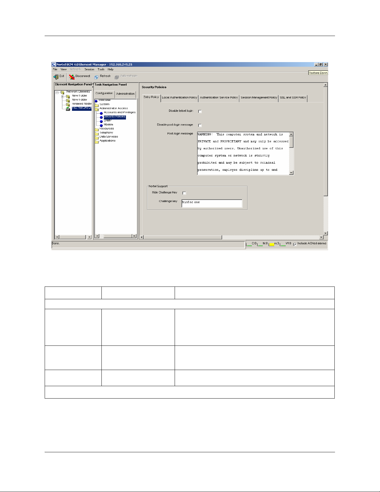
76 Chapter 4 BCM50 Security Policies and Accounts and Privileges
Figure 20 Security Policies panel
The following table describes the fields on this panel:.
Table 17 Security Policies fields
Attribute Value Description
Entry Policy tab
Disable telset login check box When selected, specifies when users cannot access the system
Disable post-login
message
Post login message text Displays the post-login security warning. The warning can be
Nortel Support
check box When checked, specifies that the post-login security warning
through any telset interface. Default: unchecked
Tip: If this is enabled, and DHCP changes the system IP
address, you can determine the new IP address by way of the
OAM port.
will not open on login. Default: not checked
edited to customize the message for your system.
NN40020-600NN40020-600
Page 77

Chapter 4 BCM50 Security Policies and Accounts and Privileges 77
Table 17 Security Policies fields (Continued)
Attribute Value Description
Challenge key Specifies an alphanumeric key. This key is part of the access
information your service technician requires to remotely access
your system. Default: trust no one.
If you change the default string, retain a record of the new string
so that Nortel Technical Support can access your system
during a support service call.
This key must be at least one character long to allow Nortel
support operation.
Hide Challenge Key check box When checked, displays asterisks to hide the characters used
Local Authentication Policy tab
Credential Complexity
in the challenge key. Default: not checked.
Credential Type Element Manager:
Minimum User ID
length
Minimum password
length
Password
Complexity Level
(Element Manager)
Alphanumeric
Telset: Numeric
Element Manager:
Alphanumeric 1-32
Telset: Numeric 1-16
Element Manager:
Alphanumeric 1-32
Telset: Numeric 1-16
0
1
2
3
4
5
Specifies the variety of characters an alphanumeric password
must have. The required number of each type is defined by the
complexity level.
Note: User IDs are not case-sensitive.
Telset interface passwords must be numerical. Password
complexity for these passwords defines how many unique digits
are required.
Specifies the minimum number of characters that the system
requires for each type of credential.
Specifies the minimum number of characters that must be
entered for a new password.
Note: Alphanumeric passwords are case-sensitive.
Note: This setting must be the same as or greater than the
complexity level setting.
Example: If you have a complexity level of two, two different
types of characters or two unique numbers, the password must
be at least two characters long.
Defines the number of character types required for an
alphanumeric password. Default: 3
0: No complexity checks
1: only one character type is required
2: at least two character types are required
3: at least three character types are required.
4: all four character types are required.
5: prevent consecutive numbering.
Note: A password complexity higher than 0 will ensure that the
user name is not used as the password. Check minimum length
setting to ensure that it is equal to or greater than the
complexity level.
Password complexity consists of the following types:
• upper case alphabet (English)
• lower case alphabet (English)
• westernized Arabic numbers
• non-alphanumeric characters ($, !, %, ^, period, comma)
BCM50 Administration Guide
Page 78

78 Chapter 4 BCM50 Security Policies and Accounts and Privileges
Table 17 Security Policies fields (Continued)
Attribute Value Description
Password
Complexity Level
(telset interface)
Lockout on Failed Logon
Enable lockout check box When checked, specifies that enable lockout rules apply to
Lockout counter digits Specifies the number of times the user can attempt to enter an
Lockout duration
(min)
Lockout counter
reset
Password Expiry
Enable password
expiry
Days before
password expire
Warning days before
password expire
Password History
Enable password
history
Password history
length
1
2
3
4
5
minutes Specifies the amount of time after the user is locked out before
minutes Specifies the number of minutes after a lockout before the
check box When checked, specifies that the account will expire at a
up to 256 Enter the number of days the a password can remain valid
checkbox When checked, the BCM stores a list of previously used
numeric value Enter the number of previously used passwords to be stored
Specifies the number of unique digits that must be part of a
telset password:
0: No complexity checks
1: one unique digit
2: two unique digits
3: three unique digits
4: four unique digits
5: prevent consecutive numbering
Note: A password complexity higher than 0 will ensure that the
user name is not used as the password. Check the minimum
length setting to ensure that it is equal to or greater than the
complexity level.
users.
invalid password before the user is locked out. Default: 25; for
increased security, set this number to 5.
Refer to “View by Accounts” on page 114 (Locked Out box) and
“View by Accounts: General” on page 116 (Login History)
they are allowed to login again. Reset the lockout counter to
zero. Default: 30
lockout counter is automatically reset to zero. Default: 30
Example: If the lockout counter reset is set at 30 minutes and a
user enters invalid passwords, but does not reach the lockout
counter threshold, then waits 30 minutes before trying again,
the lockout counter resets and begins counting from 1 again.
If the user enters invalid passwords until the lockout counter
threshold is reached, the Lockout duration determines when the
user can sign back onto the system.
specified time.
before it must be changed.
Enter the number of days prior to password expiry that a user
will receive notification.
passwords and prevents users from re-using them.
and checked for this account to prevent password re-use.
Authentication Service Policy tab
NN40020-600NN40020-600
Page 79

Chapter 4 BCM50 Security Policies and Accounts and Privileges 79
Table 17 Security Policies fields (Continued)
Attribute Value Description
Account
management
Server priority Primary
Server name alphanumeric Name of the RADIUS server.
Server IP address <IP address> IP address of the RADIUS server.
Server Port numeric Port number of the RADIUS server.
Enabled checkbox When selected, specifies that RADIUS authentication will be
Configuration
Server shared secret alphanumeric Key required for the BCM to communicate with the RADIUS
Server message
timeout
Server retries numeric Number of times to retry connecting with the primary server
Statistics
Last used read-only The date and time of the last attempted connection with the
Access accept read-only The number of Access Accept messages exchanged between
Access reject read-only The number of Access Reject messages exchanged between
No response read-only The number of No Response messages exchanged between
drop down menu Specifies the method used for authenticating users when they
log in. Options are Local Authentication and RADIUS. If
RADIUS is selected, you must also select the Enabled check
box.
Specifies which RADIUS server will be used as the primary
Secondary
numeric Length of time to wait for the server to respond to a request for
server for authentication, and which server will be used as a
secondary server to authenticate users when the primary server
is unavailable.
used. You must also select this check box before the BCM will
use RADIUS authentication.
server. Nortel recommends that the key be at least 64
characters in length.
authentication before timing out. Nortel recommends a setting
of 2.
before using an alternate means of authenticating the user.
Nortel recommends a setting of 2.
RADIUS server.
the RADIUS server and the BCM50.
the RADIUS server and the BCM50.
the RADIUS server and the BCM50.
Session Management Policy tab
Session time out
(min.)
Active sessions
User ID read-only Displays the user ID of the active session.
IP address read-only Displays the IP address of the active session.
Login date read-only Displays the login date of the active session.
SSL and SSH Policy tab
SSL
minutes Specifies the number of minutes a logged-in user account can
be inactive before the system ends the session and logs out the
account. If this field is left blank, the session is only ended when
the user logs off.
BCM50 Administration Guide
Page 80

80 Chapter 4 BCM50 Security Policies and Accounts and Privileges
Table 17 Security Policies fields (Continued)
Attribute Value Description
Install Web Server
Certificate (SSL)
SSH
Fingerprint alphanumeric Displays an indentifier for the application security certificate.
Generate new SSH
key-pair
Transfer Public Key
Button Downloads application security certificates to the server where
SSH is running to ensure a secure copy connection for
operations like backup and restore, upgrades and patches.
Button Opens the file system browser to allow a system-specific
security certificate and the accompanying Private key to be
selected for SSL.
Button Downloads a public security certificate or an SSH key-pair to an
SFTP server.
Configuring system security policies
This section provides procedures for setting system-level security that applies to all configured
users, for installing the web server certificate, and for downloading the SSH key-pair. Use the tabs
on the security policies panel to perform the following procedures.
Entry Policy tab
Use the Entry Policy tab to perform the following procedure:
• “Setting system access control policies” on page 81
Local Authentication Policy tab
Use the Local Authentication Policy tab to perform the following procedures:
• “Setting credential complexity” on page 81
• “Setting lockout policy for failed logins” on page 82
• “Setting password expiry policy” on page 83
• “Setting password history policy” on page 83
Authentication Service Policy tab
Use the Authentication Service Policy tab to perform the following procedures:
• “Setting the authentication method” on page 83
• “Configuring an authentication server” on page 84
NN40020-600NN40020-600
Page 81

Chapter 4 BCM50 Security Policies and Accounts and Privileges 81
Session Management Policy tab
Use the Session Management Policy tab to perform the following procedure:
• “Setting the idle session timeout” on page 88
SSL and SSH Policy tab
Use the SSL and SSH Policy tab to perform the following procedures:
• “Uploading a Web Server Certificate” on page 88
• “Transferring an SSH Key-Pair” on page 89
Setting system access control policies
Setting system access control policies allows the administrator to set system access rules.
To set system access control policies
1 Select Configuration > Administrator Access > Security Policies > Entry Policy.
2 Click in the Disable post-login message box to prevent the Warning message from opening
after login. Leave this box unchecked if you want the Warning delivered.
3 Enter a new warning in the Post-login message box, or leave the default warning in the box.
4 Click in the Disable telset login box to prevent users from having administrating the system
through any telset interface.
5 Use the default Nortel Challenge Key, or enter a new one. If you enter a new Nortel
Challenge Key, make a record of the challenge key you use. Check the Show/Hide box if you
want to display asterisks rather than the characters used in the Challenge Key.
Setting credential complexity
Setting credential complexity allows the administrator to define the rules for password length and
password complexity.
To set credential complexity
1 Select Configuration > Administrator Access > Security Policies > Local Authentication
Policy.
2 In the Credential Complexity section, under the Credential Type column, select the
credential type.
3 Under the Minimum User ID Length column, enter the required number of characters or
digits for a user’s ID.
4 Under the Minimum Password Length column, enter the required number of characters or
digits for the user’s password.
BCM50 Administration Guide
Page 82

82 Chapter 4 BCM50 Security Policies and Accounts and Privileges
5 Under the Password Complexity Level column, enter a number from 1 to 5 that represents
the password complexity level requirement, or enter 0 if no complexity check is required. For
an alphanumeric password, the level is from 0 to 4. For a numeric password, the level is from 0
to 5.
Variable Table
Variable Value
Complexity Level (Element
Manager)
Complexity Level (Telset)
0: no complexity checks
1: only one character type is required
2: at least two character types are required
3: at least three character types are required.
4: all four character types are required
A password complexity higher than 0 will ensure
that the user name is not used as the password.
The four character types are:
• lowercase letters
• uppercase letters
• numbers
• !^,.@#$%& and spaces
0: no complexity checks
1: one unique digit
2: two unique digits
3: three unique digits
4: four unique digits
5: prevent consecutive numbering (For example,
1935 or 8634971 are valid passwords. Passwords
such as 1234, 3456, 2468, 8642,8765, or 9753
would be invalid.)
Setting lockout policy for failed logins
Setting Lockout on Failed Login allows the administrator to set lockout rules. Administrators can
unlock accounts that have been locked out; see “Re-enable a locked-out user” on page 96 for more
information.
To set lockout policy for failed logins
1 Select Configuration, Administrator Access, Security Policies > Local Authentication
Policy.
2 In the Lockout on Failed Login section, select the Enable lockout check box to enable
lockout capabilities.
3 In the Lockout counter box, enter a number that represents the number of times a user can try
to login with an incorrect password.
NN40020-600NN40020-600
Page 83

Chapter 4 BCM50 Security Policies and Accounts and Privileges 83
4 In the Lockout duration box, enter the number of minutes the user is locked out after the
Lockout counter threshold is reached.
5 In the Lockout counter reset box, enter the number of minutes to wait to reset the Lockout
counter.
Setting password expiry policy
Use this procedure to enable a password expiry policy.
To set password expiry policy
1 Select Configuration, Administrator Access, Security Policies > Local Authentication
Policy.
2 In the Days before password expire box, enter the number of days that a password can be
used before it expires.
3 In the Warning days before password expire box, enter the number of days prior to password
expiry that the user will receive a notification.
4 Select the Enable checkbox to enable the password expiry policy.
Setting password history policy
You can use the password history feature to prevent users from re-using the same password.
Administrators can configure the number of previous passwords to store and check.
To set password history
1 Select Configuration, Administrator Access, Security Policies > Local Authentication
Policy.
2 In the Password history section, select the Enable Password History box.
3 In the Password history length box, enter the number of previous passwords to store and
check for an account.
Setting the authentication method
By default, users are authenticated on the local BCM50 system. In a network with mutliple
BCM50 systems, you can choose to authenticate users on a centralized server using RADIUS
(Remote Authentication Dial In User Service).
The BCM RADIUS client is compliant with the RADIUS protocol described in RFC 2865, and
supports the following authentication and authorization functions:
• ACCESS-REQUEST messages
• ACCESS-ACCEPT messages
Other functions, such as challenge key and accounting messages, are not supported.
BCM50 Administration Guide
Page 84

84 Chapter 4 BCM50 Security Policies and Accounts and Privileges
If you use RADIUS for authenticating and authorizing users, and the RADIUS servers are not
in-service or are out-of-contact, the BCM will revert to using local authentication.
When you select RADIUS as the authentication method, user IDs and passwords will be
authenticated on the RADIUS server for the following tasks:
• administration of the BCM using Element Manager
• access to the BCM website
• access to the BCM Monitor
• dial-in access to the BCM using modem or ISDN
• Contact Centre administration
• BCM Amp configuration
• CTE DA ProAE
• telset administration
• IP set registration
• voicemail and web-based administration
• Call Detail Recording functionality
To set the authentication method
1 Select Configuration, Administrator Access, Security Policies > Authentication Service
Policy.
2 From the Account Management drop-down menu, select Local Authentication or RADIUS.
If you select RADIUS, follow the procedure for “Configuring an authentication server” on
page 84.
Configuring an authentication server
To authenticate users on a centralized RADIUS server, you must configure the server using
Element Manager.
To configure an authentication server in Element Manager
1 Select Configuration, Administrator Access, Security Policies > Authentication Service
Policy.
2 Select a server to be the primary authentication server. Click in each column of the table to
enter the following attributes:
Column Value
Server name
Server IP address
NN40020-600NN40020-600
Name of the server to be used for authentication
IP address of the server to be used for
authentication
Page 85

Chapter 4 BCM50 Security Policies and Accounts and Privileges 85
Server Port
Enabled
Port number of the server to be used for
authentication
Check to enable the use of a RADIUS server
authentication.
3 Click on the Configuration tab in the details area and enter the following attributes:
Column Value
Shared Secret
Server Message Timeout
Server Retries
Key required for the BCM to communicate with
the authentication server
Length of time to wait for the server to respond to
a request for authentication before timing out
Number of times to retry connecting with the
primary server before using an alternate means of
authenticating the user.
4 Repeat steps 2 and 3 to configure the secondary server.
Vendor specific attributes
The BCM requires Vendor Specific Attributes (VSAs) to be present in RADIUS client requests.
The BCM Webpage provides a RADIUS dictionary that defines the Nortel-specific attributes. The
attributes in the dictionary are defined for a Funk RADIUS server; however, the RADIUS client in
BCM complies with RFC 2865 and can be used on other RADIUS servers.
In an ACCESS-REQUEST message, the BCM will look for the attributes listed in Table 18.
Table 18 Attributes in an ACCESS-REQUEST message
Attribute Name Description
NAS Identifier
IP
Calling Station ID
The hostname of the BCM (string)
The IP address of the BCM
The IP address/DN of the client attempting the
request
In an ACCESS-ACCEPT message, the BCM will look for the attributes listed in Table 19.
BCM50 Administration Guide
Page 86

86 Chapter 4 BCM50 Security Policies and Accounts and Privileges
Table 19 Attributes in an ACCESS-ACCEPT message
Attribute Name Value Description
RADIUS attribute type 26
Vendor type 562
Vendor attribute type 166
Privilege level
0-36 (see
Ta bl e 2 0 )
Vendor specific attribute
Northern Telecom (Nortel)
BCM privilege level of the user
being authenticated. Enter this
level as a hex integer.
Privilege level of user, entered in
big endian (network byte order).
BCM requires the RADIUS server to provide one or more privilege levels when the user
authentication is accepted. Table 20 lists the privilege levels. These must be provided as a 32-bit
integer in big endian format (network byte order).
NN40020-600NN40020-600
Page 87

Table 20 Privilege levels
Chapter 4 BCM50 Security Policies and Accounts and Privileges 87
Privilege name Value
VoiceMailAdmin 0
Contact Center 1
SBAInstaller 2
SBASystemCoord 3
SBASystemCoordBasic 4
SBABasic 5
Security 6
CTEApp 7
SBA - IP Set Registration 8
Application - BCMMonitor 9
CDRApp 10
Modem Login 11
GuestLogin 12
AdminDownload 13
ExclusiveAccess 14
Admin 16
Description
Voice Mail Administrator
MMCC - Administrator
Set Based Administrator Level 4
Set Based Administrator Level 3
Set Based Administrator Level 2
Set Based Administrator Level 1
Security Administrator
LAN CTE DA Pro AE User
IP set registration privilege - from
IP telephone sets
BCM Monitor user
CDR Application Privilege
Dial-in PPP user
Access to BCM Web pages - user
level
Administrative application
download
Access to the BCM when exclusive
access flag enabled.
Access to the BCM configuration.
DataAdmin 17
RemoteAccess 18
Guest 19
VoiceAdmin 20
BackupOperator 21
RemoteMonitoring 22
SoftwareUpgrade 23
AlarmViewer 24
Access to the data portion of CIM/
XML interface.
Access to remote access fields of
BCM configuration.
Access to all of the BCM
configuration for read-only access.
The ability to administer the
telephony portion of the BCM
configuration.
The ability to backup a BCM.
The ability to remotely connect to
and manage the BCM configuration
(ie. SNMP configuration).
The ability to upgrade the BCM.
The ability to view the alarm
screen.
BCM50 Administration Guide
Page 88

88 Chapter 4 BCM50 Security Policies and Accounts and Privileges
Operational Logs 26
Diagnostic Logs 27
ISDN - Dial-in 30
WAN - Dial-in 32
The ability to download operational
logs.
Full access to download any logs.
The ability to use ISDN for dial-in.
The ability to use WAN for dial-in
PPP access.
Setting the idle session timeout
You can use the idle session timeout feature to automatically log out users who have been inactive
for a specified period of time. Follow this procedure to specify the period of time before inactive
sessions are timed out.
To set the idle session timeout
1 Select Configuration, Administrator Access, Security Policies > Session Management
Policy.
2 In the Session timeout box, enter the number of minutes to wait after a period of inactivity
before the session times out.
Uploading a Web Server Certificate
This procedure allows you to upload a private security certificate to replace the generic web
certificate provided with BCM50. Using a custom site-specific certificate, you can have site
validation which will eliminate the security warnings.
For further information about security certificates, see “Security certificate” on page 124.
To upload a Web Server Certificate
1 Select Configuration, Administrator Access, Security Policies > SSL and SSH Policy.
2 In the SSL section, click the Install Web Server Certificate button.
3 On the Transfer Certificate browse panel, locate and select the security certificate file.
4 Click the Transfer Certificate button.
5 On the Transfer Private Key browse panel, locate and select the private key file.
6 Click the Transfer Private Key button.
7 On the Install Web Server certificate window, click OK to install the certificate.
NN40020-600NN40020-600
Page 89

Chapter 4 BCM50 Security Policies and Accounts and Privileges 89
Transferring an SSH Key-Pair
Transferring an SSH Key-Pair allows the administrator to download a public security certificate or
an SSH key-pair. The new certificate must be installed on each sftp server the BCM50
communicates with to ensure a secure connection for operations like backup and restore, and
software updates
.
To transfer an SSH Key-Pair
1 Select Configuration, Administrator Access, Security Policies > SSL and SSH Policy.
2 In the SSH section, click the Generate New SSH Key-pair button.
The new key is put on the computer running BCM50.
3 Click OK to save the new pair, or click Transfer to transfer the pair.
Configuring user accounts, user groups and privileges
User Management provides procedures for managing access to both the Element Manager and to
the telset configuration menus. You can control when users can log on, how much they can see,
and what they can do within the configuration menus.
The Accounts and Privileges context panels allow you to:
• view the user ID and last successful login of the current user
• view user accounts and add, delete, and modify accounts
• view group profiles and add, delete, and modify groups
BCM50 Administration Guide
Page 90

90 Chapter 4 BCM50 Security Policies and Accounts and Privileges
Job Aid
These links provide navigation to the sections of the panel for each user management item:
Panel tabs Tasks
“Current Account” on page 111 “Enabling and disabling exclusive access” on page 97
“View by Accounts” on page 114 • “Adding a new user account” on page 90
• “Modifying a user account” on page 91
• “Deleting a user account” on page 92
• “Changing a user’s password” on page 93
• “Changing the current user’s password” on page 93
• “Adding callback for a dial-up user” on page 92
• “Re-enable a locked-out user” on page 96
“View by Accounts: General” on page
116
• “Enabling and disabling an account” on page 96
“View by Accounts: Group Membership”
on page 117
“View by Groups” on page 118 • “Creating a group” on page 94
“View by Groups: General” on page 118 • “Modifying group privileges” on page 94
“View by Groups: Members” on page 120 • “Adding a user account to a group” on page 95
Click on the navigation tree heading, then press F1 to access general information about user management.
• “Adding a user account to a group” on page 95
• “Deleting a user account from a group” on page 95
• “Deleting a group” on page 94
• “Deleting a user account from a group” on page 95
Security note: This symbol is used throughout this section to indicate areas of possible
security concern, primarily in regard to default settings that could pose a security risk if
!
they are not changed.
Adding a new user account
Administrators can create user accounts when the BCM is configured to authenticate users locally.
After you create a new user account, you can assign groups to that account. Groups are sets of
privileges based on user tasks or roles. For information about creating groups and assigning groups
to accounts, see “Creating a group” on page 94 and “Adding a user account to a group” on page 95.
To add a new user account
1 Select Configuration, Administrator Access, Accounts and Privileges, View by Account
tab.
2 Click the Add button.
NN40020-600NN40020-600
Page 91

Chapter 4 BCM50 Security Policies and Accounts and Privileges 91
3 In the Add Account dialog box, enter a description of the account in the Description field.
4 Enter the user’s identifier in the User ID field.
5 In the User password field, enter the user’s password.
6 In the Confirm password dialog box, enter the user’s password again.
7 In the Telset password field, enter the telset password for the user.
8 In the Confirm password dialog box, enter the user’s password again.
9 If the user is connecting through a modem, enter the number the system dials to contact the
client modem in the Modem Callback Number field and enter a passcode in the Modem
Callback Passcode field. Ensure you include the correct routing codes.
10 If the user is connecting through ISDN, enter the number the system dials to contact the client
in the ISDN Callback Number field and enter a passcode in the ISDN Callback Passcode
field.
11 Select the Change Password on Login checkbox to force a password change when the user
logs into Element Manager.
12 Select the Change Password on Login Telset checkbox to force a password change when the
user logs into Telset.
13 Click OK to save the user account.
After the account is created, the user can change their own password through the Current Account
panel. Refer to “Changing the current user’s password” on page 93.
Modifying a user account
As an administrator, you can modify user accounts.
To modify a user account
1 Select Configuration, Administrator Access, Accounts and Privileges, View by Account
tab.
2 Select an existing user on the Accounts table and click the Modify button.
3 On the Modify Account dialog box, make the changes you require.
4 If callback for dial-up users is required, see “Adding callback for a dial-up user” on page 92.
5 If telset access is required, see “Adding Telset access for a user” on page 92.
6 Click OK to save the user account.
BCM50 Administration Guide
Page 92

92 Chapter 4 BCM50 Security Policies and Accounts and Privileges
Adding callback for a dial-up user
As an administrator, you can provide callback access to a user who is accessing the system through
a dial-up connection.
Callback security
!
If a user is connecting to the system using a modem, you can enhance your access
security by assigning that person a specific user account that prompts the system to
acknowledge the user, then hang up and dial back the user at a designated telephone
number, before allowing the person to have access to the system.
To add callback for a dial-up user
1 Select Configuration, Administrator Access, Accounts and Privileges, View by Account,
Remote Access tab.
2 Select an existing user on the Accounts table.
3 If the user is connecting through a modem, enter the number the system dials to contact the
client modem in the Modem Callback Number field and enter a passcode in the Modem
Callback Passcode field. Ensure you include the correct routing codes.
4 If the user is connecting through ISDN, enter the number the system dials to contact the client
in the ISDN Callback Number field and enter a passcode in the ISDN Callback Passcode
field.
5 Click OK.
Adding Telset access for a user
As an administrator, you can provide an existing user with access to the system through a
set-based connection.
To add Telset access for a user
1 Select Configuration, Administrator Access, Accounts and Privileges, View by Account
tab.
2 Select an existing user on the Accounts table and click the Modify button.
3 In the Tel s et Us er ID field, enter the user’s identifier.
4 In the Telset Password field, enter the user’s telset password.
5 Re-enter the telset password in the Confirm Password dialog box.
6 Click OK.
Deleting a user account
As an administrator, you can delete user accounts when they are not needed.
NN40020-600NN40020-600
Page 93

Chapter 4 BCM50 Security Policies and Accounts and Privileges 93
To delete a user account
1 Select Configuration, Administrator Access, Accounts and Privileges, and click the View
by Account tab.
2 Select a user on the Accounts table.
3 Click the Delete button.
4 In the confirmation box, click Ye s to remove the user account from the system.
Changing a user’s password
As an administrator, you can change a user’s forgotten password, or reset the user password for
each user to enforce regular password-change policy. You can also force a password change when
the user logs in.
\
Security note: An integral part of your system security is password management. This
includes changing default passwords after the system is installed. To further increase
!
access security, minimize the number of user accounts, especially the administrator
accounts, and change passwords regularly.
To change a user’s password
1 Select Configuration, Administrator Access, Accounts and Privileges, View by Account
tab.
2 Select the user record from the table and click Modify.
3 In the Modify Account window, delete the asterisks in the Password or Telset password
field.
4 Enter a new password and click OK.
5 Re-enter the password in the Confirm Password dialog box.
6 Provide the user with this password and request that they change it as soon as possible through
the Current User panel (“Current Account” on page 111) or click on Change Password on
Login to make a password change mandatory.
Changing the current user’s password
As a user or an administrator, you must change your password periodically.
To change the current user’s password
1 Select Configuration, Administrator Access, Accounts and Privileges, Current Account
panel.
2 Select the password field that needs to be changed.
BCM50 Administration Guide
Page 94

94 Chapter 4 BCM50 Security Policies and Accounts and Privileges
3 Enter a new password that conforms with the system password policies, which are defined by
the administrator during system setup.
A confirmation dialog box appears.
4 In the confirmation dialog box, enter the new password again.
5 Click OK.
The password takes effect the next time you log in.
Creating a group
As an administrator, you can create new groups to satisfy organizational requirements.
To create a group
1 Select Configuration, Administrator Access, Accounts and Privileges, View by Groups
tab.
2 Click the Add button.
3 In the Add Group dialog box, enter a name for the new group.
4 Click OK.
5 Select the new group from the Groups list.
6 In the Group Privileges area, click the Add button.
7 In the Add Privilege to Group dialog box, select one or more group privileges to assign to the
group and click OK. See “Default groups” on page 99 and “Default access privileges
excluding set-based privileges” on page 101 for more information.
8 Populate the group using “Adding a user account to a group” on page 95.
Deleting a group
As an administrator, you can delete groups as organizational requirements change.
To delete a group
1 Select Configuration, Administrator Access, Accounts and Privileges, View by Groups
tab.
2 Select a group and click the Delete button.
3 Click Ye s on the confirmation box to remove the groups from the list.
Modifying group privileges
Only user-created groups can be modified; default group privileges cannot be modified.
NN40020-600NN40020-600
Page 95

Chapter 4 BCM50 Security Policies and Accounts and Privileges 95
To modify group privileges
1 Select Configuration, Administrator Access, Accounts and Privileges, View by Groups
tab.
2 Select a group and then click the General tab.
3 To remove privileges, click on the Group Privileges tab, select one or more group privileges
to delete from the existing group, and click Delete. A confirmation dialog box appears; click
Ye s to delete the selected items.
4 To add privileges, click on the Group Privileges tab, select one or more group privileges to
add to the existing group, and click the Add button. See “Default groups” on page 99 and
“Default access privileges excluding set-based privileges” on page 101 for more information.
5 Click Ye s on the confirmation box to remove the groups from the list.
Adding a user account to a group
As an administrator, you can add user accounts to one or more groups to satisfy access
requirements.
To add a user account to a group
1 Select Configuration, Administrator Access, Accounts and Privileges, and click the View
by Accounts tab.
2 Select a user account and then click the Group Membership tab.
3 Click the Add button.
4 In the Add Account to Group dialog box, select one or more groups.
5 Click OK.
Deleting a user account from a group
As an administrator, you can remove user accounts from a group to limit a user’s access.
To delete a user account from a group
1 Select Configuration, Administrator Access, Accounts and Privileges, and click the View
by Accounts tab.
2 Select a user account and then click the Group Membership tab.
3 Select one or more groups on the Accounts in the Member of Groups table.
4 Click the Delete button.
5 Click OK on the confirmation box to remove the groups from the list.
BCM50 Administration Guide
Page 96

96 Chapter 4 BCM50 Security Policies and Accounts and Privileges
Re-enable a locked-out user
As the administrator you can re-enable a locked-out user when the user has exceeded the login
retry threshold.
The system shows an enabled check box under the Locked Out column on the Accounts table.
To release a locked-out user
1 Select Configuration, Administrator Access, Accounts and Privileges, View by Accounts
tab.
2 Select the user record with the Locked Out status check box checked.
3 Click the Locked out check box to clear it.
Enabling and disabling an account
As the administrator, you can enable or disable accounts on an immediate basis or a timed basis.
Security note: Remember to disable unused accounts.
!
To enable or disable an account immediately
1 Select Configuration, Administrator Access, Accounts and Privileges, View by Accounts
tab.
2 Select the user you want to disable/enable on the Accounts table.
3 Under the Disabled column, either check (disable) or clear (enable) the check box for the user.
The change will apply to the user’s next login.
To enable or disable an account on a timed basis
1 Select Configuration, Administrator Access, Accounts and Privileges, View by Accounts
tab.
2 Select the user you want to disable/enable on the Accounts table.
3 Click in the Account will be disabled field, and choose the date and time the account is to be
disabled.
4 On the General panel, ensure that Enable account expiry is selected.
NN40020-600NN40020-600
Page 97

Chapter 4 BCM50 Security Policies and Accounts and Privileges 97
Enabling and disabling exclusive access
As the administrator, you can enable or disable exclusive access for special activities or
maintenance. The administrator performing maintenance tasks can lock the system during the
maintenance period. When you enable exclusive access, this capability prevents new logins but
does not affect existing logins. This functionality is available to administrators only.
To enable/disable exclusive access
1 Select Configuration, Administrator Access, Accounts and Privileges, Current Account
tab.
2 Click Enable Exclusive Access.
3 In the Enable Exclusive Access dialog box, select a duration in minutes from the drop-down
box that represents the amount of time you want to have exclusive access to the system.
The timer begins to count down. When it reaches zero, exclusive access ends.
4 If you no longer need exclusive access, click Disable Exclusive Access to stop the timer and
end exclusive access.
User account and user group management fundamentals
This section contains information on the following topics:
• User accounts on page 97
• Default passwords on page 99
• Default groups on page 99
• Default access privileges excluding set-based privileges on page 101
• Telset access security on page 109
• Blocking user accounts on page 110
User accounts
User accounts are defined by:
• a unique user ID that is visible only to authenticating services; Element Manager IDs are
alphanumeric, and Telset IDs are numeric
• a unique user name assigned for either or both the Element Manager and telset configuration
that has a minimum length that you define when you set up the security policies
• a unique password assigned for any user ID that is defined. Either password must satisfy the
Password Policy settings for the system that you define when you set up the security policies.
• a list of group attributes which allow the user specific access privileges in the system
BCM50 Administration Guide
Page 98

98 Chapter 4 BCM50 Security Policies and Accounts and Privileges
After you create an account, you can assign groups to that account. Groups are sets of privileges
based on user tasks or roles. For example, if you have a user who is responsible for remote
monitoring, you can create an account for that user and then assign a group to the account; the
group that you assign would contain the appropriate privileges for that role. The BCM has default
groups available, but you can refine the privileges available within a group to suit the needs of
your network. In this example, you could assign the default group called Remote Monitoring,
which would allow the user to do such things as view metrics and alarms.
You can create up to 200 accounts that require privileges in Element Manager, such as IPSec and
PPP. This number does not include accounts supported for voicemail users, and contact center
agents.
The User ID of the account profiles created through the set based interface cannot be modified
through the Element Manager.
Two default user accounts are provided:
• The nnadmin account is read only and cannot be deleted or disabled
• The nnguest account provides customers with web-only access. All access to the Apache web
server requires a valid administrator username and password
Auditing for user accounts includes:
• creation date, time, and the user ID that created the account
• modify date, time, and the user ID that modified the account
• expiry date and time, if enabled
• login history, including failed attempts and the date and time of the last successful attempt
• an audit log that tracks logged-in user transactions, including user account changes
Remote users can have a callback number assigned as well. This feature allows authentication of
remote users calling in through a modem. After authentication, the BCM50 will call the user back
at the number specified.
Nortel recommends that each user have a separate user account (User Name) with a unique
password. These are set up by a user with administrator privileges in the Element Manager. The
password only shows up as asterisks on the Element Manager panel. If the password is lost, the
administrator can reset the password for the user by re-entering the password in the user account.
Each user can access their own user information and change their password. User accounts can be
disabled, either manually or through dated expiry.
On the telset administration menu (F9*8), only the administrator (SBAInstaller) can enable or
disable the telset user IDs and modify or delete telset user passwords.
NN40020-600NN40020-600
Page 99

Default passwords
The following table lists the available default passwords for the Element Manager interface, the
telset interface, and the voice mail interface.
Table 21 Default passwords
Chapter 4 BCM50 Security Policies and Accounts and Privileges 99
Default
User ID
nnadmin PlsChgMe! 738662 266344 Read-only installer/system
nnguest nnguest
voicemailadmin PlsChgMe!
– setup
*This account is not created by default. You must add a voicemail account using F9*8.
password
Telset ID
738266 266344 Set-based installer level no
738727 727587 Set-based administration no
738236 23646 Set-based coordinator functions no
738227 22742 Set-based basic access no
738862 266344 Voicemail admin* no
– – Router no
Default telset
password
Function
administrator
Read-only web-only access yes
New accounts are created from the startup profile with a default password of Time4Chg!
Security note: The default Administrator password has full access to the system. The
default password should be changed as soon as the initial system setup is complete and
!
system function is verified.
Default groups
Available at
startup?
yes
The BCM comes with a number of default read-only groups that provide a predetermined set of
access privileges. You can assign additional privileges to groups. Table 22 lists the default
privilege levels for each default group, which are described in “Default access privileges
excluding set-based privileges” on page 101 and “Telset access security” on page 109.
Table 22 Default user account groups
Group Name Privileges Notes
SBA Installer SBAInstaller
IP Set Registration
SBA Coordinator+ SBASystemCoord SBA - System Coordinator+ group access privileges on page 110
SBA Coordinator SBASystemCoordBasic
Guests
SBA Basic SBABasic SBA - Basic group access privileges on page 110
Voice & Contact Center
Group
VoiceMailAdmin Only access to voicemail/contact center administration if this is
SBA - Installer group access privileges on page 110
IP Set Registration access privileges on page 102
SBA - System Coordinator group access privileges on page 110
Guests access privileges on page 105
the only group assigned to a user account.
Voice Mail & Contact Center access privileges on page 101.
BCM50 Administration Guide
Page 100

100 Chapter 4 BCM50 Security Policies and Accounts and Privileges
Table 22 Default user account groups (Continued)
Group Name Privileges Notes
Contact Center Contact Center Only access to the Contact Centre application is available if this
is the only group assigned to a user account.
Contact Center access privileges on page 101
CDR Application CDRApp Only access to the call detail record functions is available if this is
the only group assigned to a user account.
CDR Appl access privileges on page 103
CTE Application CTEAppl CTE Appl access privileges on page 102
BCM Monitor
Application
Administrator IP Set Registration
BCMMonitorAppl BCMMonitor Appl access privileges on page 103
IP Set Registration access privileges on page 102
BCMMonitorApp
CDRApp
PPP
AdminDownload
Exclusive Access
Admin
DataAdmins
Remote Access
Voice Admins
Backup Operators
Software Upgrade
Alarm Viewer
SBA Installer
Security
CTE Appl
Operational Logs
Diagnostic Logs
VoiceMail and Contact
Center
Network IPSec
Modem dial out
ISDN dial in
ISDN dial out
WAN dial in
WAN dial out
PPOE dial in
PPOE dial out
BCMMonitor Appl access privileges on page 103
CDR Appl access privileges on page 103
PPP Access access privileges on page 103
Admin Download access privileges on page 103
Exclusive Access access privileges on page 104
Admin access privileges on page 104
DATA Admins group access privileges on page 104
Remote Access access privileges on page 105
Voice Admins access privileges on page 105
Backup Operators access privileges on page 106
Software Upgrade access privileges on page 106
Alarm Viewer access privileges on page 107
SBA - Installer group access privileges on page 110
Security access privileges on page 102
CTE Appl access privileges on page 102
Operational Logs access privileges on page 107
Diagnostic Logs access privileges on page 107
Voice Mail & Contact Center access privileges on page 101
Network IPSec access privileges on page 107
Modem dial out access privileges on page 107
ISDN dial in access privileges on page 107
ISDN dial out access privileges on page 108
WAN dial in access privileges on page 108
WAN dial out access privileges on page 108
PPPoE dial in access privileges on page 108
PPPoE dial out access privileges on page 108
Data Admin DATAAdmins DATA Admins group access privileges on page 104
Remote Access PPP
RemoteAccess
Guest Guests Guests access privileges on page 105
Voice Admin IP Set Registration
Voic eAdmins
Alarm Viewer
Power Users IP Set Registration
DATAAdmins
Voic eAdmins
Alarm Viewer
VoiceMail and Contact
Center
PPP Access access privileges on page 103
Remote Access access privileges
IP Set Registration access privileges on page 102
Voice Admins access privileges on page 105
Alarm Viewer access privileges on page 107
IP Set Registration access privileges on page 102
DATA Admins group access privileges on page 104
Voice Admins access privileges on page 105
Alarm Viewer access privileges on page 107
Voice Mail & Contact Center access privileges on page 101
on page 105
NN40020-600NN40020-600
 Loading...