

Page 1

Nortel Business Communications Manager 450
Maintenance
Release: 5.0
Document Revision: 02.03
NN40170-503
Page 2

Document status: Standard
Document issue: 02.04
Document date: August 2009
Product release: BCM 5.0
Job function: Maintenance
Type: NTP
Language type: English
Copyright © 2009 Nortel Networks
All Rights Reserved.
NORTEL, the globemark design, and the NORTEL corporate logo are trademarks of Nortel
Networks.
Maxell is a trademark of Hitachi Maxell, Ltd.
All other trademarks are the property of their respective owners.
Page 3

Contents
New in this release 5
Features 5
Introduction 7
System maintenance 9
BCM450 equipment replacement 11
BCM450 internal component replacement 13
Replacing a media bay module 15
Removing the power supply 16
Connecting the new power supply 17
Removing the hard disk 17
Installing the hard disk 18
Installing the CEC 19
Replacing memory 21
Removing the cooling fan 22
Installing the fan 22
Replacing the clock/calendar battery 23
Prerequisites 15
Procedure steps 15
Prerequisites 21
Prerequisites 24
Procedure steps 24
Redundant power supply installation 25
Prerequisites for redundant power supply installation 25
Redundant power supply installation navigation 26
Removing the PSU status connector jumper 26
Procedure steps 27
Installing the redundant power supply cage 28
Procedure steps 28
Installing the secondary cooling fan 31
Procedure steps 32
Installing the power supply modules 33
Copyright © 2009 Nortel Networks
Business Communications Manager 450
Maintenance
NN40170-503 02.04 Standard
August 2009
Page 4

4 Contents
Procedure steps 34
Common procedures 35
Disconnecting the cables from the main unit 35
Disconnecting the cables from the expansion cabinet 36
Shutting down the system for maintenance 36
Returning the system to operation 38
Removing the BCM450 base function tray 39
Prerequisites 39
Procedure steps 39
Reinstalling the BCM450 base function tray 40
Prerequisites 40
Procedure steps 40
Removing the BCM450 main unit top cover 40
Prerequisites 41
Procedure steps 41
Installing the main unit top cover 42
Prerequisites 42
Procedure steps 42
BCM modules management 45
Disabling or enabling a bus or module 46
Disabling or enabling a port channel setting 47
Configuring a Station Module type BCM450 MBM 47
Deconfiguring a Station Module type BCM450 MBM 48
48
Configuring a Trunk Module or Combination MBM 49
Deconfiguring a Trunk Module or Combination MBM 49
49
System LEDs reference 51
System status monitor LEDs 51
Hard disk drive LEDs on BCM450 52
Copyright © 2009 Nortel Networks
Business Communications Manager 450
Maintenance
NN40170-503 02.04 Standard
August 2009
Page 5

New in this release
The following sections detail what’s new in Nortel Business Communications
Manager 450—Maintenance in Release 5.0:
•“Features (page 5)”
Features
• BCM450 5.0 supports RAID for disk mirroring. This allows you to maintain
a redundant image of your hard drive to maintain service in the event of a
hard disk failure. For more information, see Removing the hard disk
(page 17) and Installing the hard disk (page 18).
Copyright © 2009 Nortel Networks
Business Communications Manager 450
Maintenance
NN40170-503 02.04 Standard
August 2009
Page 6

6 New in this release
Copyright © 2009 Nortel Networks
Business Communications Manager 450
Maintenance
NN40170-503 02.04 Standard
August 2009
Page 7

Introduction
This document describes how to maintain Business Communications
Manager BCM systems.
Navigation
• System maintenance (page 9)
• BCM450 equipment replacement (page 11)
• BCM450 internal component replacement (page 13)
• Redundant power supply installation (page 25)
• BCM modules management (page 45)
• Common procedures (page 35)
• System LEDs reference (page 51)
Copyright © 2009 Nortel Networks
Business Communications Manager 450
Maintenance
NN40170-503 02.04 Standard
August 2009
Page 8

8 Introduction
Copyright © 2009 Nortel Networks
Business Communications Manager 450
Maintenance
NN40170-503 02.04 Standard
August 2009
Page 9

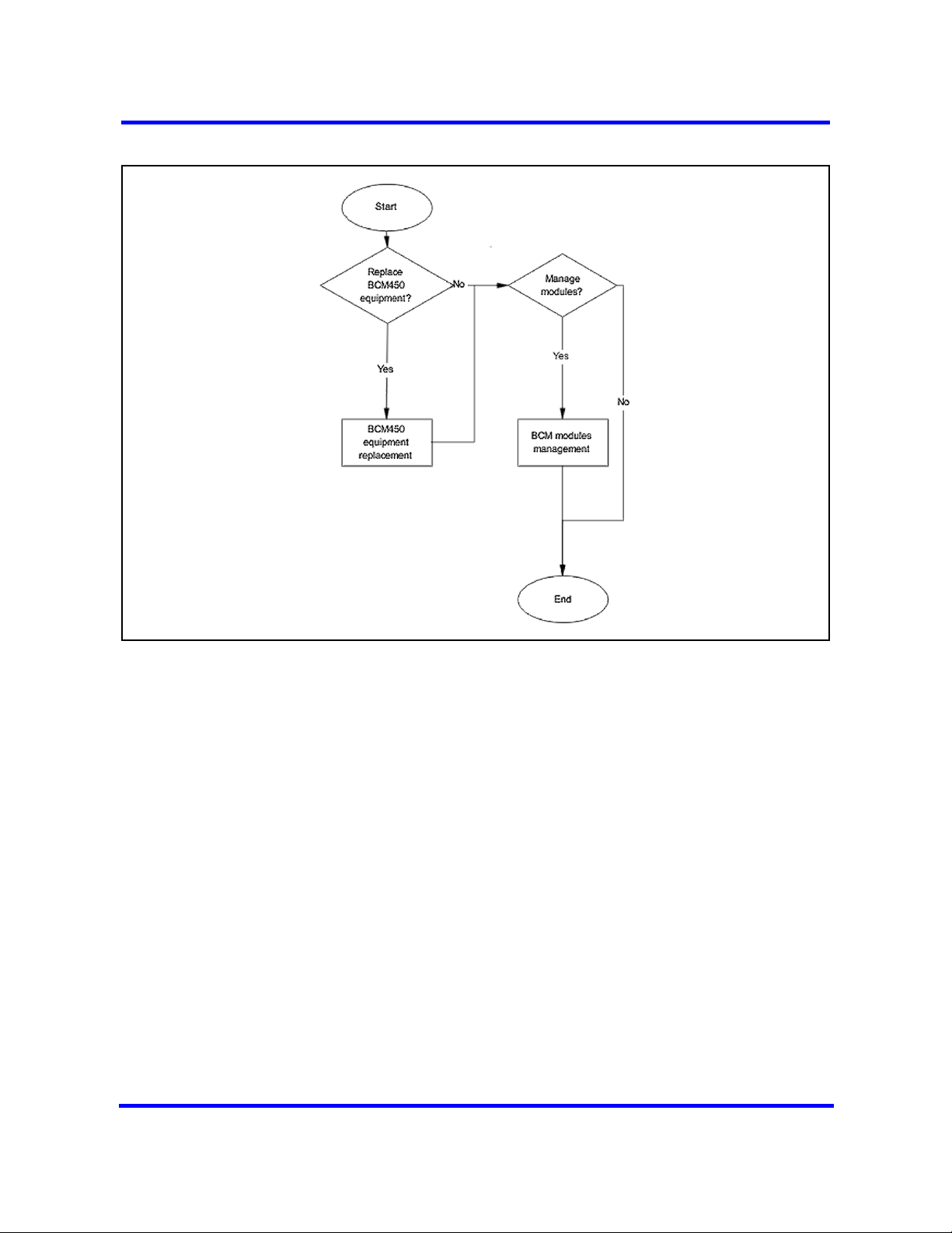
System maintenance
To maintain your Business Communications Manager (BCM) system, you can
replace damaged equipment, manage installed modules, and use BCM
utilities to monitor performance and track statistics.
Prerequisites to system maintenance
• Ensure your BCM system is properly installed. For more information about
installing a BCM system, see Nortel Business Communications Manager
450 5.0 Installation — System (NN40170-303).
System maintenance tasks
This work flow shows you the sequence of tasks you perform to maintain your
BCM system. To link to any tasks, click on System maintenance navigation
(page 10).
Copyright © 2009 Nortel Networks
Business Communications Manager 450
Maintenance
NN40170-503 02.04 Standard
August 2009
Page 10
10 System maintenance
Figure 1 System maintenance tasks
System maintenance navigation
• BCM450 equipment replacement (page 11)
• BCM modules management (page 45)
Copyright © 2009 Nortel Networks
Business Communications Manager 450
Maintenance
NN40170-503 02.04 Standard
August 2009
Page 11

BCM450 equipment replacement
Replace BCM450 equipment and components when they are damaged.
WARNING
Risk of leakage currents
You must disconnect the telephony and data networking cables from
the system before disconnecting the power cord from a grounded
outlet.
Equipment replacement tasks
This work flow shows you the sequence of tasks you perform to replace
equipment for your BCM450 system. To link to any tasks, click on Equipment
replacement navigation (page 12).
Copyright © 2009 Nortel Networks
Business Communications Manager 450
Maintenance
NN40170-503 02.04 Standard
August 2009
Page 12

12 BCM450 equipment replacement
Figure 2 Equipment replacement tasks
Equipment replacement navigation
• BCM450 internal component replacement (page 13)
Copyright © 2009 Nortel Networks
Business Communications Manager 450
Maintenance
NN40170-503 02.04 Standard
August 2009
Page 13
BCM450 internal component replacement
You can replace components in the BCM450 main unit if they are defective or
damaged.
Prerequisites to BCM450 internal component replacement
• Ensure the BCM450 system is shut down. For more information, see
Shutting down the system for maintenance (page 36).
• Disconnect the main unit from the power outlet.
• Remove the BCM450 main unit from the rack, wall, or desktop and set it
on a flat, clean, static-free surface.
• Ensure you have the following tools:
— Phillips screwdriver #2, with a 3.5-inch blade
— 3/16-inch slot screwdriver
— Antistatic wrist grounding strap
CAUTION
Risk of damage to equipment
You must wear an antistatic grounding strap at all times when
handling electronic components. Failure to do so can result in
damage to the equipment.
Copyright © 2009 Nortel Networks
CAUTION
Risk of information loss and damage to equipment
Do not use an electric or magnetized screwdriver near the hard disk.
You can lose the information stored on the disk. Shock can damage
the hard disk. Do not drop or hit the hard disk.
Business Communications Manager 450
Maintenance
NN40170-503 02.04 Standard
August 2009
Page 14

14 BCM450 internal component replacement
BCM450 internal component replacement procedures
This task flow shows you the sequence of procedures you perform to replace
an internal component in a BCM450 main unit. To link to any procedure, click
on BCM450 internal component replacement navigation (page 14).
Figure 3 BCM450 internal component replacement procedures
BCM450 internal component replacement navigation
• Replacing a media bay module (page 15)
• Removing the power supply (page 16)
• Connecting the new power supply (page 17)
• Removing the hard disk (page 17)
• Installing the hard disk (page 18)
• Installing the CEC (page 19)
• Replacing memory (page 21)
• Removing the cooling fan (page 22)
• Installing the fan (page 22)
• Replacing the clock/calendar battery (page 23)
Copyright © 2009 Nortel Networks
Business Communications Manager 450
Maintenance
NN40170-503 02.04 Standard
August 2009
Page 15

Replacing a media bay module
This section describes how to replace a media bay module (MBM) installed in
your BCM450 main unit or expansion cabinet if it is defective or damaged.
This section describes replacing an MBM with the same type of MBM. If you
want to replace an MBM with a different type of MBM, you must treat it as a
new installation. Ensure the new MBM does not overrun any lines already
assigned to other MBMs.
Prerequisites
• Turn off the BCM450 system. For more information, see “Shutting down
the system for maintenance (page 36)”.
• Ensure the BCM450 main unit is disconnected from the AC power source.
Procedure steps
Step Action
1 Remove any cabling from the MBM faceplate.
BCM450 internal component replacement 15
2 Grasp the right edge of the MBM ejector lever with your thumb, index and
middle fingers.
3 Pull outward to partially eject the MBM. Pull further on the lever to eject the
MBM from the bay.
4 Grasp the top and bottom edges of the MBM, and remove it from the BCM
unit. Place the MBM in a clean, safe, and static-free area.
5 Set the DIP switches on the new MBM to match the settings of the old MBM.
6 Install the new MBM in the main unit or expansion cabinet. For more
information about installing an MBM, see Nortel Business Communications
Manager 450 Installation — System.
7 Return the BCM450 system to normal operation.
--End--
Copyright © 2009 Nortel Networks
Business Communications Manager 450
Maintenance
NN40170-503 02.04 Standard
August 2009
Page 16
16 BCM450 internal component replacement
Removing the power supply
Remove the defective power supply from your BCM450 main unit or BCM450
expansion cabinet before installing the new power supply.
WARNING
Risk of leakage currents
You must disconnect the telephony and data networking cables from
the system before disconnecting the power cord from a grounded
outlet.
CAUTION
Risk of equipment damage
Protect the hardware components against damage from electrostatic discharge. Always wear a grounded wrist strap before
you handle components. Always place the components in a
static-free container.
Procedure steps
Step Action
1 Shut down the BCM450 system. For more information, see Shutting down
the system for maintenance (page 36).
2 Disconnect all cables from the front of the base function tray.
3 Disconnect the main unit and the expansion cabinet (if applicable) from the
AC power connection.
4 Attach one end of the grounding strap to your wrist and the other end to a
grounded metal surface.
5 Loosen the screws securing the power supply module (located at the back
of the unit, on the right).
6 Pull handle located on the power supply module outward to remove the
power supply module from the unit.
--End--
Copyright © 2009 Nortel Networks
Business Communications Manager 450
Maintenance
NN40170-503 02.04 Standard
August 2009
Page 17
Connecting the new power supply
After you remove the defective power supply, connect the new power supply
to your BCM450 main unit or BCM450 expansion cabinets.
Prerequisites
• Ensure that the new power supply is an auto adjust power supply.
Procedure steps
Step Action
1 Firmly slide the power supply module directly into the power supply bay.
2 Tighten the screws to secure the power supply module.
Removing the hard disk
Remove the damaged hard disk before installing the new hard disk.
BCM450 internal component replacement 17
--End--
Procedure steps
Step Action
1 In Business Element Manager, go to Administration >System
Metrics>Disk Mirroring. Determine whether it is HDD-1 in the first (left)
hard disk slot or HDD-2 in the second (right) slot that has failed.
The Status section will list one of the drives as Failed and not Passed. If the
system has been rebooted since the failure has occurred, depending on the
type of hard disk failure, a second drive may not be listed in this section. In
that case, the drive that is installed but does not have a lit HDD LED and is
not listed in the Status section will be the failed disk to be replaced.
2 Turn off the BCM450 system and disconnect it from the AC power source.
For more information, see Shutting down the system for maintenance
(page 36).
CAUTION
Risk of damage to equipment
Do not use an electric or magnetized screwdriver near the hard disk.
You can lose the information stored on the disk. Shock can damage
the hard disk. Do not drop or hit the hard disk.
Copyright © 2009 Nortel Networks
Business Communications Manager 450
Maintenance
NN40170-503 02.04 Standard
August 2009
Page 18

18 BCM450 internal component replacement
3 Attach one end of a grounding strap to your wrist and the other end to a
grounded metal surface.
4 On the bottom left of the base function tray, loosen the thumb screw and
remove the hard disk bay faceplate.
5 Using your thumb and forefinger, pull hard disk bracket forward, out of the
main unit.
Figure 4 Hard disk bay faceplate
Remove this
screw
Hard disk bay
faceplate
6 Lift the failed hard disk and hard disk bracket from the main unit, and place
them on a flat, clean, static-free surface.
7 Remove the four screws that secure the hard disk to the hard disk bracket.
8 Lift the hard disk from the hard disk bracket, and set it on a flat, clean, static-
free surface.
Installing the hard disk
Install the new hard disk into the BCM450 main unit.
Prerequisites
• Remove the hard disk. For more information about removing the hard disk,
see “Removing the hard disk (page 17).”
--End--
Copyright © 2009 Nortel Networks
Business Communications Manager 450
Maintenance
NN40170-503 02.04 Standard
August 2009
Page 19

Procedure steps
Step Action
1 Attach one end of a grounding strap to your wrist and the other end to a
grounded metal surface.
2 Place the new hard disk in the hard disk bracket.
3 Use the four hard disk bracket screws to secure the hard disk to the bracket.
4 Push the hard disk and bracket forward into the hard disk bay (the left most
slot).
5 Press down lightly on the top of the hard disk to ensure that the hard disk
bracket is seated properly.
BCM450 internal component replacement 19
CAUTION
Risk of equipment damage
Use only the screws that you removed from the hard disk. Using
other screws can damage the hard disk.
6 Replace the hard disk bay panel, and tighten the thumb screw.
7 Restart the BCM450.
8 In Business Element Manager, go to Administration >System
9 In the Operation mode field, under the Settings sub-panel, select Mirror
Installing the CEC
You can install the optional compact expansion card (CEC) to increase the
capacity of the BCM450 system.
Prerequisites
• Turn off the BCM450 system. For more information, see “Shutting down
the system for maintenance (page 36)”.
The HDD LED (or both HDD LEDs if a redundant hard disk is present)
should be green indicating that the replacement disk was installed correctly.
Metrics>Disk Mirroring.
Mode to enable disk mirroring to maintain a redundant hard disk if you have
two hard disks installed. Otherwise, ensure that HDD-1 is selected.
--End--
• Ensure the BCM450 main unit is disconnected from the AC power source.
Copyright © 2009 Nortel Networks
Business Communications Manager 450
Maintenance
NN40170-503 02.04 Standard
August 2009
Page 20

20 BCM450 internal component replacement
CAUTION
Risk of damage to equipment
You must wear an antistatic grounding strap at all times when
handling electronic components. Failure to do so can result in
damage to the equipment.
Procedure steps
Step Action
1 Turn off the BCM450 system, and remove the base function tray.
2 Attach one end of a grounding strap to your wrist and the other end to a
grounded metal surface.
3 Remove the plastic cap on the CEC slot on the front of the base function tray.
Figure 5 CEC slot
4 Screw the four metal standoffs (included) into the main board of the base
5 Slide the CEC into position from the back of the base function tray, so that
6 Align the connectors on the card and on the main board of the base function
7 Use the four supplied screws to fasten the card to the standoffs.
8 Reinstall the base function tray and power on the BCM450 system.
Copyright © 2009 Nortel Networks
CEC slot
function tray.
the CEC protrudes slightly from the front faceplate of the base function tray.
tray and push down. Ensure that the card is connected securely to the main
board.
Business Communications Manager 450
Maintenance
NN40170-503 02.04 Standard
August 2009
Page 21

Replacing memory
Use the following procedure to replace the random access memory card in the
BCM450 main unit if it is defective or damaged.
Prerequisites
• Ensure that you have available a replacement DDR RAM card (up to
1gigabyte, 533 megahertz).
Procedure steps
Step Action
1 Shut down the system. For more information, see Shutting down the system
2 Disconnect the BCM450 system from the AC power outlet.
3 Disconnect any connectors from the front of the base function tray.
BCM450 internal component replacement 21
--End--
for maintenance (page 36).
4 Attach one end of the grounding strap to your wrist and the other end to a
grounded metal surface.
5 Remove the base function tray. For more information see Removing the
BCM450 base function tray (page 39).
6 Carefully push down on the fastening tabs on either side of the DIMM. As
you press down on the fastening tabs, the DIMM lifts out of the DIMM slot.
7 Grasp both ends of the DIMM with your fingertips. Lift the DIMM up and
away from the DIMM slot. Place the DIMM in a static-free container.
8 Position and correctly align the new DIMM (edge connectors first) into the
connector.
9 Carefully and firmly press down on the top of the DIMM card with your
thumbs. At the same time, use your index fingers to move the fastening tabs
inward toward the card.
When the card is completely inserted in the connector, the fastening tabs
clip to the side of the DIMM card.
10 Reinstall the base function tray. For more information, see Reinstalling the
BCM450 base function tray (page 40).
11 Insert all connectors in the correct locations on the base function tray face.
12 Restore the BCM system to operation.
Copyright © 2009 Nortel Networks
--End--
Business Communications Manager 450
Maintenance
NN40170-503 02.04 Standard
August 2009
Page 22

22 BCM450 internal component replacement
Removing the cooling fan
Remove the existing cooling fan before you install a new cooling fan in the
BCM450 main unit.
Prerequisites
• Turn off the BCM450 system. For more information, see Shutting down the
system for maintenance (page 36).
• Ensure the BCM450 main unit is disconnected from the AC power source.
Procedure steps
Step Action
1 Attach one end of a grounding strap to your wrist and the other end to a
grounded metal surface.
2 Locate the fan access panel at the rear of the main unit.
3 Remove the fan access panel screws at the top of the panel. Place the
screws in a safe location.
4 Tip the top of the fan access panel toward you.
5 Grasp the fan access panel with both hands and lift the away from the main
6 Disconnect the fan cable connector from the base function tray connector.
7 Remove the four snap rivets that hold the fan to the fan access panel. The
8 With your fingernails, gently separate the plastic rivet pin from the center of
9 Remove the rivet center pin and collar from the fan access panel and place
10 Lift the fan away from the fan access panel and place it in a safe location.
Installing the fan
After removing the defective or damaged fan, install the new fan into the
BCM450 main unit.
Prerequisites
• Remove the existing fan. For more information about removing the fan,
see “Removing the cooling fan (page 22).”
unit. Do not stretch the fan cables.
snap rivet has two parts: a center pin and a collar.
the rivet collar.
them in a safe location.
--End--
Copyright © 2009 Nortel Networks
Business Communications Manager 450
Maintenance
NN40170-503 02.04 Standard
August 2009
Page 23

Procedure steps
Step Action
1 Attach one end of a grounding strap to your wrist and the other end to a
grounded metal surface.
2 Place the new fan in the fan access panel in the same position as the old fan.
3 Ensure the fan cable is oriented to the bottom of the fan and that the fan
label is closest to the grill on the panel.
Attention: Ensure the label of the new fan faces the back of the BCM450 unit. Air
must flow out of the unit as indicated by the embossed arrows on the fan.
4 Align the fan chassis mounting holes with the holes in the fan access panel.
5 Hold the fan in place against the fan access panel and push the rivet collar
through the fan access panel and fan chassis mounting holes.
6 Insert the rivet pin into the rivet collar.
7 Connect the fan cable connector to the base function tray connector.
BCM450 internal component replacement 23
8 Mount the fan access panel to the main unit.
9 Tip the top of the fan access panel toward you.
10 Insert the bottom lip of the fan access panel in the main unit.
11 Align the screw holes in the fan access panel with the screw holes on the
main unit.
12 Install and tighten the fan access panel screws.
13 Restore the BCM450 system to operation.
14 To test the direction of the fan exhaust, hold a piece of paper or your hand
close to the fan exhaust. A correctly installed fan blows air away from the
main unit.
15 If the fan exhaust air flow is incorrect, remove the cooling fan and reinstall it
in the correct position.
Replacing the clock/calendar battery
This section describes how to remove and install the clock/calendar battery
located on the main card when it ceases to function. The clock/calendar
battery supplies the power required to keep the CMOS information current if
there is a power failure.
--End--
Copyright © 2009 Nortel Networks
Business Communications Manager 450
Maintenance
NN40170-503 02.04 Standard
August 2009
Page 24

24 BCM450 internal component replacement
Attention: You must replace the battery with a CR2032, 3 Volt Maxell coin
cell battery. The use of any other manufacturer can invalidate the safety
approval of the BCM450 main unit and possibly cause a fire or explosion.
Prerequisites
• Shut down the BCM450 system. For more information, see “Shutting down
the system for maintenance (page 36)”.
• Remove the base function tray. For more information, see “Removing the
BCM450 base function tray (page 39)”.
Procedure steps
Step Action
1 Locate the clock battery on the main board of the base function tray.
2 Use your finger to carefully lift the battery out of the socket. Do not use any
type of tool to remove the battery.
3 Position the new battery on top of the battery socket. Ensure you have the
positive side of the battery facing up.
4 Push down until the battery snaps into the socket.
5 Reinstall the base function tray.
6 Restore the BCM system to operation.
--End--
Copyright © 2009 Nortel Networks
Business Communications Manager 450
Maintenance
NN40170-503 02.04 Standard
August 2009
Page 25

Redundant power supply installation
This chapter describes how to install the optional redundant power supply and
cooling fan into the BCM450 main unit.
Each power supply has its own AC power connector, an Audible Fail Alarm
shutoff button, and a power switch.
Attention: Both power switches must be turned on at all times. When
shutting down the BCM system, disconnect the power cords from the AC
power source; do not turn the power switches off.
Prerequisites for redundant power supply installation
• You require a redundant power supply upgrade kit (NTC03180TXE6).
Redundant power supply installation procedures
The following task flow shows you the sequence of procedures you perform
the sequence of tasks you perform to install a redundant power supply and
cooling fan in your BCM450 system. To link to any procedure, select
Redundant power supply installation navigation (page 26).
Copyright © 2009 Nortel Networks
Business Communications Manager 450
Maintenance
NN40170-503 02.04 Standard
August 2009
Page 26

26 Redundant power supply installation
Figure 6 Redundant power supply installation tasks
Redundant power supply installation navigation
• Removing the PSU status connector jumper (page 26)
• Installing the redundant power supply cage (page 28)
• Installing the secondary cooling fan (page 31)
• Installing the power supply modules (page 33)
Removing the PSU status connector jumper
Perform the following procedure to remove the power supply unit (PSU) status
connector jumper if you are installing a redundant power supply in the
BCM450 main unit for the first time.
Prerequisites
• Turn off the BCM450 system.
• You require a Phillips head screwdriver.
• Ensure you disconnect the BCM450 main unit from the AC power source.
Business Communications Manager 450
NN40170-503 02.04 Standard
Copyright © 2009 Nortel Networks
Maintenance
August 2009
Page 27

Procedure steps
Step Action
1 Turn off the BCM450 system.
2 Disconnect the BCM450 system from the AC power outlet.
3 Attach one end of a grounding strap to your wrist and the other end to a
grounded metal surface.
4 Remove the main unit top cover.
5 Locate the PSU status connector on the Chassis Interface (CIF) card.
Redundant power supply installation 27
CAUTION
Risk of damage to equipment
You must wear an antistatic grounding strap at all times when
handling electronic components. Failure to do so can result in
damage to the equipment.
PSU Status connector
6 Remove the RPS output signaling connector jumper (this is the only jumper
on the board). Use needle-nose pliers to pull the jumper out and away from
the connector.
7 Connect the PA cable to the PSU Status connector.
Copyright © 2009 Nortel Networks
Business Communications Manager 450
Maintenance
NN40170-503 02.04 Standard
August 2009
Page 28

28 Redundant power supply installation
--End--
Installing the redundant power supply cage
Perform the following procedure to install the redundant power supply cage in
the main unit.
Prerequisites
• Turn off the BCM450 system.
• You require a Phillips head screwdriver.
• Ensure you disconnect the BCM450 main unit from the AC power source.
• Remove the standard power supply from the main unit. For more
information, see Removing the power supply (page 16)
CAUTION
Risk of damage to equipment
You must wear an antistatic grounding strap at all times when
handling electronic components. Failure to do so can result in
damage to the equipment.
Procedure steps
Step Action
1 Turn off the BCM450 system.
2 Disconnect the BCM450 system from the AC power outlet.
3 Attach one end of a grounding strap to your wrist and the other end to a
grounded metal surface.
4 Remove the standard power supply from the BCM450 main unit.
5 Remove the power supply support bracket from the main unit by removing
the interior and exterior mounting screws. Place the screws in a safe
location.
Copyright © 2009 Nortel Networks
Business Communications Manager 450
Maintenance
NN40170-503 02.04 Standard
August 2009
Page 29

Redundant power supply installation 29
6 Remove the power supply adapter tab from the support bracket. Use pliers
to bend and snap the tab away from the support bracket. Ensure you remove
only the inner adapter tab.
7 Remove the knockout bracket from the rear of the main unit.
8 Remove both power supply modules from the redundant power supply cage
9 Place the redundant power supply (top down) on a flat surface. Place the
10 Insert a tie-wrap in the power supply support bracket lanclet.
11 Gather together, and then route the motherboard 20-pin power cable (P1),
12 Secure the cables to the power supply support bracket with the tie-wrap.
Copyright © 2009 Nortel Networks
before you install the power supply in the main unit.
power supply support bracket on the bottom surface of the power supply.
the +12 V power cable (P9), the 3.3 V load cable (PB), and the PS monitor
cable (PA) to the tie-wrap.
Business Communications Manager 450
Maintenance
NN40170-503 02.04 Standard
August 2009
Page 30

30 Redundant power supply installation
13 Install the power supply support bracket in the BCM450 main unit.
14 Position the redundant power supply cage in the main unit. Ensure the
power supply module tray opening faces the rear of the main unit.
15 Attach the redundant power supply cage to the main unit using the four
chassis mounting screws.
16 Bundle the P2, P3, P4, P5, P6, P7, and P8 cables together. Run the cables
on the top of the power supply chassis, and then secure with the cable
clamp.
17 Connect cable P2 (all cables are labeled on the connector) into the bottom
media bay module backplane power connector.
18 Connect cable P3 into the top media bay module backplane connector.
19 Bundle P2, P3, P4, P5, P6, P7, and P8 together with a grommet to prevent
the cables from being pinched by the base function tray.
Copyright © 2009 Nortel Networks
Business Communications Manager 450
Maintenance
NN40170-503 02.04 Standard
August 2009
Page 31

Redundant power supply installation 31
d
s
.
20 Insert the P2, P3, P4, P5, P6, P7, and P8 into the cable slot on the chassis
(secured with the grommet).
Insert the P2, P3,
P4, P5, P6, P7, an
P8 auxiliary cable
into the cable slot
21 Ensure that one power run connects to one MBM backplane connector.
Each power run has multiple connectors. Do not connect a single power run
to both MBM backplane connectors.
22 Connect the 4-pin PSU AUX cable to the 4-pin AUX connector.
23 Connect the 20-pin PSU Main cable to the PSU Main connector.
24 Install the main unit top cover.
Installing the secondary cooling fan
Perform the following procedure to install the secondary cooling fan after you
install the redundant power supply cage.
Prerequisites
• Turn off the BCM450 system.
• You require a Phillips head screwdriver.
• Ensure you disconnect the BCM450 main unit from the AC power source.
CAUTION
Risk of damage to equipment
You must wear an antistatic grounding strap at all times when
handling electronic components. Failure to do so can result in
damage to the equipment.
--End--
Copyright © 2009 Nortel Networks
Business Communications Manager 450
Maintenance
NN40170-503 02.04 Standard
August 2009
Page 32

32 Redundant power supply installation
Procedure steps
Step Action
1 Attach one end of a grounding strap to your wrist and the other end to a
grounded metal surface.
2 Remove the fan access panel screws at the top and bottom of the panel.
Place the screws in a safe location.
3 Tip the top of the fan access panel toward you.
4 Grasp the fan access panel with both hands, and then lift it away from the
main unit. Do not stretch the fan cables.
5 Disconnect the CIF card fan cables.
6 Remove the snap rivets that hold the fan to the fan access panel. The snap
rivet has two parts: a center pin and a collar. Gently separate the plastic rivet
pin with your fingernail from the center of the rivet collar. Remove the rivet
pin and collar from the fan access panel. Place the rivet pin and collar in a
safe location.
7 Lift the fan away from the fan access panel. Put the old fan access panel in
a safe location.
8 Place one of the fans on the new fan access panel, over one of the grills.
9 Ensure you orient the fan cable to the bottom of the fan and that the fan label
is closest to the grill on the panel.
Attention: Ensure the label of the new fan faces the back of the BCM450 unit. Air
must flow out of the unit as indicated by the embossed arrows on the fan.
10 Align the fan chassis mounting holes with the holes in the fan access panel.
11 Hold the fan in place against the fan access panel, and then push the rivet
collar through the fan access panel and fan chassis mounting holes.
12 Insert the rivet pin into the rivet collar.
13 Repeat steps 8 through 12 for the second fan.
Copyright © 2009 Nortel Networks
Business Communications Manager 450
Maintenance
NN40170-503 02.04 Standard
August 2009
Page 33

Redundant power supply installation 33
14 Connect the fan cable connector of the leftmost fan (when looking at the
back of the BCM450) to the Fan 1 connector on the CIF card.
Fan 1
Fan 2
15 Connect the second fan cable connector to the Fan 2 connector on the CIF
card.
16 Mount the fan access panel to the main unit.
17 Tip the top of the fan access panel toward you.
18 Insert the bottom lip of the fan access panel into the main unit.
19 Align the screw holes in the fan access panel with the screw holes on the
main unit.
20 Install and tighten the fan access panel screws.
21 Restore the BCM450 system to operation.
22 To test the direction of the fan exhaust, hold a piece of paper or your hand
close to the fan exhaust. A correctly installed fan blows air away from the
main unit.
23 If the fan exhaust air flow is incorrect, remove the cooling fan, or fans, and
reinstall it in the correct position.
Installing the power supply modules
Perform the following procedure to install the main and redundant power
supply modules into the power supply cage.
Prerequisites
• You must install the redundant power supply cage.
--End--
• Ensure that both the primary and secondary fans are connected properly
before restarting the system.
Copyright © 2009 Nortel Networks
Business Communications Manager 450
Maintenance
NN40170-503 02.04 Standard
August 2009
Page 34

34 Redundant power supply installation
CAUTION
Risk of damage to equipment
You must wear an antistatic grounding strap at all times when
handling electronic components. Failure to do so can result in
damage to the equipment.
Procedure steps
Step Action
1 Position the power supply modules in the redundant power supply cage.
Ensure they are oriented correctly (the power status light must be on the top
right corner).
2 Push on the power supply module until the face of the module is flush with
the casing. You can hear a click when the power supply module is properly
seated.
3 Secure each module with the power supply locking nut (located on the right
4 Ensure the power switches are both set to the ON position before turning on
5 Connect both AC power cords to AC outlets. If only one cord is connected,
6 Turn on the BCM450 system. Ensure both power status lights are on, and
Copyright © 2009 Nortel Networks
side of the module).
the BCM system.
only the connected power supply functions.
that the fans are functioning properly.
--End--
Business Communications Manager 450
Maintenance
NN40170-503 02.04 Standard
August 2009
Page 35

Common procedures
The following sections describe common procedures that you use while
maintaining the BCM system.
Navigation
• Disconnecting the cables from the main unit (page 35)
• Disconnecting the cables from the expansion cabinet (page 36)
• Shutting down the system for maintenance (page 36)
• Returning the system to operation (page 38)
• Removing the BCM450 base function tray (page 39)
• Reinstalling the BCM450 base function tray (page 40)
• Removing the BCM450 main unit top cover (page 40)
• Installing the main unit top cover (page 42)
Disconnecting the cables from the main unit
Disconnect the cables from the BCM450 main unit to prepare the system for
maintenance operations.
Procedure steps
Step Action
1 Shut down the BCM450 system.
2 Remove the LAN cables from the LAN ports on the main unit.
Copyright © 2009 Nortel Networks
WARNING
Risk of leakage currents
You must disconnect the telephony and data networking cables from
the system before disconnecting the power cord from a grounded
outlet
Business Communications Manager 450
Maintenance
NN40170-503 02.04 Standard
August 2009
Page 36

36 Common procedures
3 Remove the expansion cable if the main unit is connected to an expansion
cabinet.
4 If the system uses the external Music Source port, remove the cable from
this port.
5 If the system uses a Uninterruptable Power Supply (UPS), remove the USB
cable from the USB port.
6 Remove the power supply cord from the main unit.
--End--
Disconnecting the cables from the expansion cabinet
Disconnect the cables from the BCM450 expansion cabinet to prepare the
system for maintenance operations.
Prerequisites
• Use Element Manager to disable the media bay modules (MBM) that are
installed in the expansion cabinet. For more information about disabling an
MBM, see Nortel Business Communications Manager Administration and
Security.
WARNING
Risk of leakage currents
You must disconnect the telephony and data networking cables from
the system before disconnecting the power cord from a grounded
outlet
Procedure steps
Step Action
1 Disconnect the expansion cable from the expansion port on the expansion
cabinet.
2 Disconnect all of the telephone lines and extension cables from the MBMs
inserted in the expansion cabinet. If more than one cable exists, mark the
cables to identify the port from which you removed them.
3 Remove the power supply cord from the expansion cabinet.
--End--
Shutting down the system for maintenance
Shut down the BCM450 system to prepare it for maintenance operations.
Copyright © 2009 Nortel Networks
Business Communications Manager 450
Maintenance
NN40170-503 02.04 Standard
August 2009
Page 37

Prerequisites
• Ensure you have a recent backup of the BCM450 system programming. If
a recent backup is not available, use Element Manager to back up the
system data. For information about backing up the system data, see
Nortel Business Communications Manager Administration and Security.
• Remove the telephony and data networking lines from the BCM main unit
and expansion cabinet. For more details, see Disconnecting the cables
from the main unit (page 35) and Disconnecting the cables from the
expansion cabinet (page 36).
Procedure steps
Step Action
Common procedures 37
WARNING
Risk of leakage currents
You must disconnect the telephony and data networking cables from
the system before disconnecting the power cord from a grounded
outlet.
1 Launch Element Manager.
2 From the Administration tab, click the Utilities folder to expand it.
3 From the Utilities folder, select Reset.
4 Click Shutdown BCM System to shut down the system.
The BCM system begins the shutdown process.
When the shutdown process is complete, the final warning dialog box
appears, and the system status LED becomes yellow and enters a flashing
state.
5 Click OK to disconnect Element Manager.
When the shut down is complete, the power LED becomes black, and the
status LED enters a solid yellow state.
6 Remove the DS256 cables from the front of the BCM main unit and, if
present, the expansion cabinet.
7 Mark the cables to ensure a correct reconnection.
8 Disconnect the BCM main unit and expansion cabinet power cords from the
AC outlet.
9 Ensure you have room to access the part you are working on. Remove the
BCM main unit from the rack, if necessary.
Copyright © 2009 Nortel Networks
--End--
Business Communications Manager 450
Maintenance
NN40170-503 02.04 Standard
August 2009
Page 38

38 Common procedures
Returning the system to operation
Return the BCM system to operation to restart telephony services after you
complete your maintenance operations.
Prerequisites
• For more information about installing the system, see Nortel Business
Communications Manager 450 Installation — System.
WARNING
Risk of service loss
When you restart the system, all digital telephony, IP client voice
mail, and Voice over IP (VoIP) ports are not available until the system
services restart.
WARNING
Risk of leakage currents
You must reconnect the power cord to a grounded outlet before
reconnecting the telephony and data networking cables to the
system.
Procedure steps
Step Action
1 If you removed the BCM450 main unit from the rack or wall, replace it.
2 Ensure your BCM450 power supply is connected to your BCM450 system
and to an AC wall outlet or a UPS.
3 Ensure the telephony cables are connected to the BCM main unit and BCM
expansion cabinets.
4 Check the Power and Status LEDs on the main unit. After the BCM starts,
both LEDs must be solid green. If either LED is not solid green, a problem
with the main unit exists.
For a detailed description of the LED states, see System status monitor
LEDs (page 51).
5 If this system has an expansion cabinet, check the Power and Status LEDs
on the media bay modules (MBM) in the expansion cabinet. Both LEDs must
be solid green. If either LED is not solid green, a problem exists with the
MBM or the expansion cabinet.
For a detailed description of the MBM LED states, see Nortel Business
Communications Manager 450 Installation—System.
6 Use Element Manager to restore the programming.
Copyright © 2009 Nortel Networks
Business Communications Manager 450
Maintenance
NN40170-503 02.04 Standard
August 2009
Page 39

For information about restoring system programming, see Nortel Business
Communications Manager 450 Administration and Security.
--End--
Removing the BCM450 base function tray
Remove the BCM450 base function tray from the system if it is defective or if
you need to perform maintenance on it.
Prerequisites
• You must shut down the BCM450 system. For more information, see
Shutting down the system for maintenance (page 36).
CAUTION
Risk of equipment damage
Protect the hardware components against damage from electrostatic
discharge.
Common procedures 39
Procedure steps
Step Action
1 Disconnect any connectors from the front of the base function tray.
2 Attach one end of the grounding strap to your wrist and the other end to a
grounded metal surface.
3 Remove the base function tray latch screws and place them in a safe
location.
4 Pull the base function tray latches toward you into the unlocked position.
5 Grasp the base function tray latches and pull the base function tray out of
the main unit.
6 Place the base function tray on a flat, clean, and static-free surface.
Always wear a grounded wrist strap before you handle components.
Always place the components in a static-free container.
--End--
Copyright © 2009 Nortel Networks
Business Communications Manager 450
Maintenance
NN40170-503 02.04 Standard
August 2009
Page 40

40 Common procedures
Reinstalling the BCM450 base function tray
The following procedure describes how to reinstall a BCM450 base function
tray after maintenance, or how to install a new BCM450 base function tray if it
is defective or damaged.
Prerequisites
• Ensure the main unit is disconnected from the AC power source.
CAUTION
Risk of equipment damage
Protect the hardware components against damage from electrostatic
discharge.
Always wear a grounded wrist strap before you handle components.
Always place the components in a static-free container.
Procedure steps
Step Action
1 Disconnect the BCM450 system from the AC power outlet.
2 Attach one end of the grounding strap to your wrist and the other end to a
grounded metal surface.
3 Move the base function tray latches to the unlocked position.
4 Position the base function tray in the correct main unit bay.
5 Insert the base function tray into the main unit.
6 Push the base function tray latches to the locked position.
7 Install the base function tray latch screws.
8 Insert all connectors in the correct locations on the base function tray face.
9 Restore the BCM450 system to operation.
10 Observe the system status monitor LEDs to ensure the base function tray
initializes correctly.
--End--
Removing the BCM450 main unit top cover
Use this procedure to remove the top cover of the BCM450 main unit if you want to
perform maintenance activities.
Copyright © 2009 Nortel Networks
Business Communications Manager 450
Maintenance
NN40170-503 02.04 Standard
August 2009
Page 41

Attention: Do not operate the BCM450 main unit with the top cover
removed. Do not leave the top cover removed for extended periods of time.
Prerequisites
• Ensure the BCM450 main unit is disconnected from the AC power source.
Procedure steps
Step Action
Common procedures 41
CAUTION
Risk of equipment damage
Protect the hardware components against damage from electrostatic
discharge.
Always wear a grounded wrist strap before you handle components.
Always place the components in a static-free container.
1 Shut down the system. For more information, see Shutting down the system
for maintenance (page 36).
2 Disconnect the BCM450 system from the AC power outlet.
3 If required, remove the main unit from the server rack.
4 Attach one end of the grounding strap to your wrist and the other end to a
grounded metal surface.
5 Remove the two top cover screws located at the rear of the main unit. Place
the screws in a safe location.
6 Lift the back of the cover and slide it rearward until it disengages from the
main unit.
--End--
Copyright © 2009 Nortel Networks
Business Communications Manager 450
Maintenance
NN40170-503 02.04 Standard
August 2009
Page 42

42 Common procedures
Figure 7 Removing main unit top cover
Installing the main unit top cover
Use this procedure to install the top of the main unit cover after maintenance or
installation activities are complete and you are ready to start the system.
Prerequisites
• Ensure the main unit is disconnected from the AC power source.
CAUTION
Risk of equipment damage
Protect the hardware components against damage from electrostatic
discharge.
Always wear a grounded wrist strap before you handle components.
Always place the components in a static-free container.
Procedure steps
Step Action
1 If required, remove the main unit from the server rack.
2 Attach one end of the grounding strap to your wrist and the other end to a
3 Set the top cover on the main unit.
Copyright © 2009 Nortel Networks
grounded metal surface.
Business Communications Manager 450
Maintenance
NN40170-503 02.04 Standard
August 2009
Page 43

4 Slide the top cover forward until it engages with the main unit.
5 Press the top cover down until it rests on the chassis.
6 Install the two top cover screws at the rear of the main unit.
Figure 8 Installing main unit top cover
Common procedures 43
--End--
Copyright © 2009 Nortel Networks
Business Communications Manager 450
Maintenance
NN40170-503 02.04 Standard
August 2009
Page 44

44 Common procedures
Copyright © 2009 Nortel Networks
Business Communications Manager 450
Maintenance
NN40170-503 02.04 Standard
August 2009
Page 45

BCM modules management
Determine the status of any of the settings under the media bay module
headings. To correct a problem or change a module setting, you can enable
or disable a bus or module, or select ports on the module.
Prerequisites to BCM modules management
• Launch Element Manager and connect to your BCM450 system.
BCM modules management procedures
This task flow shows you the sequence of procedures you perform to manage
modules in your BCM450 system. To link to any procedure, click on BCM
modules management navigation.
Copyright © 2009 Nortel Networks
Business Communications Manager 450
Maintenance
NN40170-503 02.04 Standard
August 2009
Page 46

46 BCM modules management
Figure 9 BCM modules management procedures
BCM modules management navigation
• Disabling or enabling a bus or module (page 46)
• Disabling or enabling a port channel setting (page 47)
• Configuring a Station Module type BCM450 MBM (page 47)
• Deconfiguring a Station Module type BCM450 MBM (page 48)
• Configuring a Trunk Module or Combination MBM (page 49)
• Deconfiguring a Trunk Module or Combination MBM (page 49)
Disabling or enabling a bus or module
Disable or enable a bus or module when you need to isolate a problem or
block access from the module.
Attention: If there is more than one module assigned to the DS30 bus, all
modules are disabled.
Business Communications Manager 450
NN40170-503 02.04 Standard
Copyright © 2009 Nortel Networks
Maintenance
August 2009
Page 47

Procedure steps
Step Action
1 In Element Manager, click Configuration > Resources > Telephony
Resources > Modules pane.
2 Select the module you wish to enable or disable.
3 Click either Enable or Disable.
4 Click OK.
--End--
Disabling or enabling a port channel setting
Disable or enable a port channel setting if you need to isolate a problem or
block access from the module, by turning off individual port channels rather
than the entire module.
Prerequisites
• A trunk media bay module has no changeable settings on the Trunk Port
Details record.
BCM modules management 47
Procedure steps
Step Action
1 In Element Manager, click Configuration > Resources > Telephony
Resources > Modules panel.
2 Click the module supporting the port you want to enable or disable.
3 On the Set Port Details tab, select the port you want to enable or disable.
4 Click either Enable or Disable.
The State box indicates the mode of operation for the port. If the port is
enabled, this box shows “unequipped” unless a device is physically
connected.
--End--
Configuring a Station Module type BCM450 MBM
You can configure BCM450 MBMs through Element Manager.
Copyright © 2009 Nortel Networks
Business Communications Manager 450
Maintenance
NN40170-503 02.04 Standard
August 2009
Page 48

48 BCM modules management
Prerequisites
• The BCM450 MBM must be installed in the system. For information about
replacing a BCM450 MBM, see Replacing a media bay module (page 15).
For information on installing a new BCM450 MBM, see
Communications Manager 450 Installation — System.
Procedure steps
Step Action
1 In Element Manager, click Configuration > Resources > Telephony
Resources > Modules pane.
2 Select the module you want to configure or deconfigure.
3 Click the Configured Device field. A menu appears.
4 Select the type of MBM you want configure.
5 Click Configure.
6 Enter the Start DN.
7 Enter the Public received digits/OLI.
Nortel Business
8 Enter the Private received digits/OLI.
9 Select or clear the Assign target lines check box (default is clear).
--End--
Deconfiguring a Station Module type BCM450 MBM
You can deconfigure BCM450 MBMs through Element Manager.
Prerequisites
• The BCM450 MBM must be installed in the system. For information about
replacing a BCM450 MBM, see Replacing a media bay module (page 15).
For information on installing a new BCM450 MBM, see
Communications Manager 450 Installation — System.
Step Action
1 In Element Manager, click Configuration > Resources > Telephony
Resources > Modules pane.
2 Select the module you want to deconfigure.
Nortel Business
3 Click Deconfigure.
4 Click OK to delete the configuration for the MBM.
Copyright © 2009 Nortel Networks
Business Communications Manager 450
Maintenance
NN40170-503 02.04 Standard
August 2009
Page 49

BCM modules management 49
--End--
Configuring a Trunk Module or Combination MBM
You can configure BCM450 MBMs through Element Manager.
Prerequisites
• The BCM450 MBM must be installed in the system. For information about
replacing a BCM450 MBM, see Replacing a media bay module (page 15).
For information on installing a new BCM450 MBM, see
Communications Manager 450 Installation — System.
Procedure steps
Step Action
1 In Element Manager, click Configuration > Resources > Telephony
Resources > Modules pane.
2 Select the module you want to configure or deconfigure.
Nortel Business
3 Click on the Configured Device field. A menu appears.
4 Select the type of MBM you want configure.
5 Click Configure.
6 Enter the Start Line.
7 Click OK.
--End--
Deconfiguring a Trunk Module or Combination MBM
You can deconfigure BCM450 MBMs through Element Manager.
Prerequisites
• The BCM450 MBM must be installed in the system. For information about
replacing a BCM450 MBM, see Replacing a media bay module (page 15).
For information on installing a new BCM450 MBM, see
Communications Manager 450 Installation — System.
Step Action
Nortel Business
1 In Element Manager, click Configuration > Resources > Telephony
Copyright © 2009 Nortel Networks
Resources > Modules pane.
Business Communications Manager 450
Maintenance
NN40170-503 02.04 Standard
August 2009
Page 50

50 BCM modules management
2 Select the module you want to deconfigure.
3 Click Deconfigure.
4 Click OK to delete the configuration for the MBM.
--End--
Copyright © 2009 Nortel Networks
Business Communications Manager 450
Maintenance
NN40170-503 02.04 Standard
August 2009
Page 51

System LEDs reference
This chapter provides information about the main unit LED status during
normal operation, startup, and reboot.
System status monitor LEDs
The BCM450 system status LEDs on the main unit provide information about
the status of the BCM450 system. Use these LEDs to determine if the system
is functioning properly and if the system generates an alarm.
The following figure shows the location of the system status and power LEDs
on the BCM450.
Figure 10 LED locations on the BCM450
System
Power
The following tables show the meanings of LED states.
Table 1 System status LEDs states and descriptions
Power Status Description
LED states seen during Start up sequence
Solid yellow Solid yellow Power applied to system
Solid yellow Off Power on self test (POST). Lasts for 9
Solid yellow Solid yellow System initializing (lasts 14 seconds).
Copyright © 2009 Nortel Networks
HDD 1
Business Communications Manager 450
Maintenance
NN40170-503 02.04 Standard
August 2009
RAID HDD 2
seconds.
Page 52

52 System LEDs reference
Table 1 System status LEDs states and descriptions
Power Status Description
Solid green Solid yellow Kernel initialization (lasts 8 seconds)
Solid green Blink green Services initializing (lasts 1 minute).
Solid green Solid green Normal operation.
Solid green Solid red Services initialization failed.
LED states seen during Safe Mode start up sequence
Solid red Solid green System running with factory default
Solid red Solid red System running in Software Reset
Solid red Blink yellow System running in Configuration
LED states seen during shut down sequence or failure
Solid green Blink yellow Graceful shutdown in progress.
Off Solid yellow Graceful shutdown completed.
or Safe OS.
settings enabled.
mode.
Reset mode.
Solid red Blink yellow Overheat detected. Thermal
Solid red Solid red Power spike or Rail power fluctuation
Blink red Solid red Rail power fluctuation. Power Monitor
Solid yellow Solid red Power spike shutdown completed
Off Off No power, system is shut down
Start-up Profile LED states (seen only during initial system install or staging)
Blink Yellow Blink Yellow Start-up Profile executing.
Solid Green Solid Green Start-up Profile successfully applied.
Blink Yellow Blink Red Start-up Profile failure.
Hard disk drive LEDs on BCM450
The following table describes the possible LED states for the hard disk drive
LEDs on the BCM450.
Table 2 HDD LED states
shutdown completed.
detected.
Shutdown completed.
(temperature and Rail power ok).
(power cable is disconnected).
Copyright © 2009 Nortel Networks
Business Communications Manager 450
Maintenance
NN40170-503 02.04 Standard
August 2009
Page 53

HDD 1 Description
Off No HDD detected
Green Normal operation
Red HDD fault
System LEDs reference 53
Orange/Flashing
Activity
Orange
HDD 1 Description
Off No HDD detected
Green Normal operation
Red HDD fault
Orange/Flashing
Activity
Orange
RAID Description
Off RAID not enabled
Green RAID is operating, HDDs are
synchronized.
Red RAID failure.
Orange/Flashing
Synchronization in progress.
Orange
Copyright © 2009 Nortel Networks
Business Communications Manager 450
Maintenance
NN40170-503 02.04 Standard
August 2009
Page 54

54 System LEDs reference
Copyright © 2009 Nortel Networks
Business Communications Manager 450
Maintenance
NN40170-503 02.04 Standard
August 2009
Page 55

Page 56

Business Communications Manager 450
Maintenance
Copyright © 2009 Nortel Networks. Sourced in Canada, the United States, and the United Kingdom.
All Rights Reserved.
Publication: NN40170-503
Document status: Standard
Document issue: 02.04
Document date: August 2009
Product release: BCM 5.0
Job function: Maintenance
Type: NTP
Language type: English
NORTEL, the globemark design, and the NORTEL corporate logo are trademarks of Nortel Networks.
Maxell is a trademark of Hitachi Maxell, Ltd.
All other trademarks are the property of their respective owners.
To provide feedback or report a problem with this document, go to www.nortel.com/documentfeedback.
 Loading...