

Page 1

BayRS Version 14.00
Part No. 308606-14.00 Rev 00
September 1999
4401 Great America Parkway
Santa Clara, CA 95054
Configuring and Troubleshooting Bay Dial VPN Services
Page 2

Copyright © 1999 Nortel Networks
All rights reserved. Printed in the USA. September 1999.
The information in this document is subject to change without notice. The statements, configurations, technical data,
and recommendations in this document are believed to be accurate and reliable, but are presented without express or
implied warranty. Users must take full responsibility for their a pplic a tions o f any products specifi ed in th is d ocum ent .
The information in this document is proprietary to Nortel Networks NA Inc.
The software described in this document is furnished under a license agreement and may only be used in accordance
with the terms of that license. A summary of the Software License is included in this document.
NORTEL NETWORKS is a trademark of Nortel Networks.
Bay Networks, BCN, BLN, and BN are registered trademarks and Advanced Remote Node, ANH, ARN, ASN,
Baystream, BayRS, BaySecure Access Control, and System 5000 are trademarks of Nortel Networks.
Microsoft, MS, MS-DOS, Win32, Windows, and Windows NT are registered trademarks of Microsoft Co rporation.
All other trademarks and registered trademarks are t he property of their respective owners.
Restricted Rights Legend
Use, duplication, or disclosure by the United States Government is subject to restrictions as set forth in subparagraph
(c)(1)(ii) of the Rights in Technical Data and Computer Sof tware clause at DFARS 252.227-7013.
Notwithstanding any other license agreement that may pertain to, or accompany the delivery of, this computer
software, the rights of the United States Government regarding its use, reproduction, and disclosure are as set forth in
the Commercial Computer Software-Restricted Rights cl ause at FAR 52.227-19.
Statement of Conditions
In the interest of improvi ng internal design, operational func tion , an d/o r re lia bi lity, Nortel Ne tworks NA Inc. re serv e s
the right to make changes to the products described in this document without notice.
Nortel Networks NA Inc. does not assume any liability that may occur due to the use or application of the product(s)
or circuit layout(s) described herein.
Portions of the code in this software product may be Copyright © 1988, Regents of the University of California. All
rights reserved. Redistribution and use in source and binary forms of such portions are permitted, provided that the
above copyright notice and this paragraph are duplicated in all such forms and that any docu mentation, advertising
materials, and other materials related to such distribution and use acknowledge that su ch portions of the software were
developed by the University of California, Berkeley. The name of the University may not be used to endorse or
promote products derived from such portions of the software without specific prior written permission.
SUCH PORTIONS OF THE SOFTWARE ARE PROVIDED “AS IS” AND WITHOUT ANY EXPRESS OR
IMPLIED WARRANTIES, INCLUDING, WITHOUT LIMITATION, THE IMPLIED WARRANTIES OF
MERCHANTABILITY AND FITNESS FOR A PARTICULAR PURPOSE.
In addition, the program and information containe d herein are licensed only pursuant to a license agreement that
contains restrictions on use and disclosure (that may incorporate by reference certain limitations and notices imposed
by third parties).
ii
308606-14.00 Rev 00
Page 3

Nortel Networks NA Inc. Software License Agreement
NOTICE: Please carefully read this license agre ement before copying or using the accompanying software or
installing the hardware unit with pre-enabled software (each of which is referred to as “Software” in this Agreement).
BY COPYING OR USING THE SOFTWARE, YOU ACCEPT ALL OF THE TERMS AND CONDITIONS OF
THIS LICENSE AGREEMENT. THE TERMS EXPRESSED IN THIS AGREEMENT ARE THE ONLY TERMS
UNDER WHICH NORTEL NETWORKS WILL PERMIT YOU TO USE THE SOFTWARE. If you do not accept
these terms and conditions, return the product, unused and in the original shipping container, within 30 days of
purchase to obtain a credit for the full purchase price.
1. License Grant. Nortel Networks NA Inc. (“Nortel Networks”) grants the end user of the Software (“Licensee”) a
personal, nonex clusive, nontransferable license: a) to use the Softw are eit her on a single compute r or, if applicable, on
a single authorized device identified by host ID, for which it was originally acquired; b) to copy the Software solely
for backup purposes in support of authorized use of t he Software; and c) to use and copy the associated user manual
solely in support of authoriz ed use of th e Softwa re b y Licen see. Thi s license applies t o the So ftware o nly and d oes not
extend to Nortel Networks Agent software or other Nortel Networks software products. Nortel Networks Agent
software or other Nortel Networks software products are licensed for use under the terms of the applicable Nortel
Networks NA Inc. Software License Agreement that accompanies such software and upon payment by the end user of
the applicable license fees for such software.
2. Restrictions on use; reservation of rights. The Software and user manuals are protected und er copyright laws.
Nortel Networks and/or its licensors retain all title and ownership in both the Software and user manuals, including
any revisions made by Nortel Networks or it s licensors. The copyright notice must be repr oduced and included wit h
any copy of any portion of the Software or user manuals. Licensee may not modify, translate, decompile, disassemble,
use for any competitive analysis, reverse engineer, distribute, or create derivative works from the Software or user
manuals or any copy, in whole or in part. Except as expressly provided in this Agreement, Licensee may not copy or
transfer the Software or user manuals, in whole or in part. The Software and user manuals embody Nortel Networks’
and its licensors’ confidential and proprietary inte lle ctu al pro p erty. Licensee shall not sublicense, assign, or otherwise
disclose to any third party the Software, or any information about the operation, design, performance, or
implementation of the Software and user manuals that is confidential to Nortel Networks and its licensors; however,
Licensee may grant permission to its consultants, subcontractors, a nd agents to use the Softw are at Licensee’s facility,
provided they have agreed to use the Software only in accordance with the terms of this license.
3. Limited warranty . Nortel Networks warrants each item of Software, as delivered by Nortel Networks and properly
installed and operated on Nortel Networks hardware or other equipment it is originally licensed for, to function
substantially as described in its accompanying user manual during its warranty period, which begins on the date
Software is first shipped to Licensee. If an y item of S oftware f ails to so function d uring its w arranty period, as the sole
remedy Nortel Networks will at its discretion provide a suitable fix, patch, or workaround for the problem that may be
included in a future Software release. Nortel Networks further warrants to Licensee that the media on which the
Software is provided will be free from defec ts in materials and wo rkman ship under no rmal use for a peri od of 90 da ys
from the date Software is first shipped to Licensee. Nortel Networks will replace defective media at no charge if it is
returned to Nortel Netw orks during the warranty period along with proof of the date of ship ment. This warranty does
not apply if the media has been damaged as a result of accident, misuse, or abuse. The Licensee assumes all
responsibility for selection of the Software to achieve Licensee’s intended results and for the installation, use, and
results obtained from the Software. Nortel Networks does not warrant a) that the functions contained in the software
will meet the Licensee’s requirements, b) that the Software will operate in the hardware or software combinations that
the Licensee may select, c) that the operation of the Software will be uninterrupted or error free, or d) that all defects
in the operation of the Softw are will be corrected . Nortel Network s is not obligated to remedy any Software de fect that
cannot be reproduced with the latest Software release. These warranties do not apply to the Software if it has been (i)
altered, except by Nortel Networks or in accordance with i ts instructions; (ii) used in conjunction with another
vendor’s product, resulting in the de fect; or (iii) damage d by improper environment, abuse, misuse, accident, or
negligence. THE FOREGOING WARRANTIES AND LIMITATIONS ARE EXCLUSIVE REMEDIES AND ARE
IN LIEU OF ALL OTHER WARRANTIES EXPRESS OR IMPLIED, INCLUDING WITHOUT LIMITATION ANY
WARRANTY OF MERCHANTABILITY OR FITNESS FOR A PARTICULAR PURPOSE. Licensee is responsible
308606-14.00 Rev 00
iii
Page 4

for the security of its own data and information and for maintaining adequate procedures apart from the Software to
reconstruct lost or altered files, data, or programs.
4. Limitation of liability. IN NO EVENT WILL NORTEL NETWORKS OR ITS LICENSORS BE LIABLE FOR
ANY COST OF SUBSTITUTE PROCUREMENT; SPECIAL, INDIRECT, INCIDENTAL, OR CONSEQUENTIAL
DAMAGES; OR ANY DAMAGES RESULTING FROM INACCURATE OR LOST DATA OR LOSS OF USE OR
PROFITS ARISING OUT OF OR IN CONNECTION WITH THE PERFORMANCE OF THE SOFTWARE, EVEN
IF NORTEL NETWORKS HAS BEEN ADVISED OF THE POSSIBILITY OF SUCH DAMAGES. IN NO EVENT
SHALL THE LIABILITY OF NORTEL NETWORKS RELATING TO THE SOFTWARE OR THIS AGREEMENT
EXCEED THE PRICE PAID TO NORTEL NETWORKS FOR THE SOFTWARE LICENSE.
5. Government Licensees. This provision applies to a ll Softwa re and docum entation acquired d irectly or i ndirectly by
or on behalf of the United States Government. The Software and documentation are commercial products, licensed on
the open market at market prices, and were developed entirely at private expense and without th e use of any U.S.
Government funds. The license to the U.S. Government is granted only with restricted rights, and use, duplication, or
disclosure by the U.S. Government is subject to the restrictions set forth in subparagraph (c)(1) of the Commercial
Computer Software––Restricte d Rig hts cla u se o f FAR 52.227-19 and the limitations se t o ut in thi s license for civilian
agencies, and subparagraph (c)(1)(ii ) of the Rights in Technical Data and Computer Software clause of DFARS
252.227-7013, for agencies of t he Department of Defense or their successors, whichever is applicable.
6. Use of Software in the European Community. This provision applies to all Software acquired for use within the
European Community. If Licensee uses the Software within a country in the European Community, the Software
Directive enacted by the Council of European Communities Directive dated 14 May, 1991, will apply to the
examination of the Software to facilitate interoperability. Licensee agrees to notify Nortel Networks of any such
intended examination of the Software an d may procure support and assistance from Nortel Networks.
7. Term and termination. This license is effective until terminated; however, all of the restrictions with respect to
Nortel Networks’ copyright in the Software and user manuals will cease being effective at the date of expiration of the
Nortel Networks copyright; those restrictions relating to use and disclosure of Nortel Networks’ confidential
information shall continue in effect. Licensee may terminate this license at any time. The license will automatically
terminate if Licensee fails to comply with any of the terms and conditions of the license. Upon termination for any
reason, Licensee will immediat ely destroy or return to Nortel Networks the Software, user manuals, and all copies.
Nortel Networks is not liable to Licensee for damages in any form solely by reason of the termination of this license.
8. Export and Re-export. Licensee agrees not to export, directly or indirectly, the Software or related technical data
or information without first obtaining any required export licenses or other governmental approvals. Without limiting
the foregoing, Licensee, on behalf of itself and its subsidiaries and affiliates, agrees that it will not, without first
obtaining all export licenses and approvals required by the U.S. Government: (i) export, re-export, transfer, or divert
any such Software or technical data, or any direct product thereof, to any country to which such exports or re-exports
are restricte d or em b argoed under United States export con tr o l la w s an d r egulations, or to an y national or resident of
such restricted or embargoed countries; or (ii) provide the Software or related technical data or information to any
military end user or for any military end use, including the design, development, or production of any chemical,
nuclear, or biological weapons.
9. General. If any provision of this Agreement is held to be invalid or unenforceable by a court of competent
jurisdiction, the remainder of the provisions of this Agreement shall remain in full force and effect. This Agreement
will be governed by the laws of the state of California.
Should you have any questions concerning this Agreement, contact Nortel Networks, 4401 Great America Par kwa y,
P.O. Box 58185, Santa Clara, California 95054-8185.
LICENSEE ACKNOWLEDGES THAT LICENSEE HAS READ THIS AGREEMENT, UNDERSTANDS IT, AND
AGREES TO BE BOUND BY ITS TERMS AND CONDITIONS. LICENSEE FURTHER AGREES THAT THIS
AGREEMENT IS THE ENTIRE AND EXCLUSIVE AGREEMENT BETWEEN NORTEL NETWORKS AND
LICENSEE, WHICH SUPERSEDES ALL PRIOR ORAL AND WRITTEN AGREEMENTS AND
COMMUNICATIONS BETWEEN THE PARTIES PERTAINING TO THE SUBJECT MATTER OF THIS
AGREEMENT. NO DIFFERENT OR ADDITIONAL TERMS WILL BE ENFORCEABLE AGAINST NORT EL
NETWORKS UNLESS NORTEL NETWORKS GIVES ITS EXPRESS WRITTEN CONSENT, INCLUDING AN
EXPRESS WAIVER OF THE TERMS OF THIS AGREEMENT.
iv
308606-14.00 Rev 00
Page 5

Contents
Preface
Before You Begin ............................................................................................................. xv
Text Conventions .............................................................................................................xvi
Acronyms ........................... .......................... .......................... ......................... ................xvii
Related Publications ........................................................................................................xix
How to Get Help ..............................................................................................................xix
Chapter 1
Tunneling Overview
Bay Dial VPN Overview .................. ...... ....... ...... ....... ...... ....... ...... ...................................1-1
What Is Tunneling? .........................................................................................................1-2
Layer 3 Tunneling ............................................................................................................1-4
Layer 2 Tunneling ............................................................................................................1-4
Comparing Layer 3 and Layer 2 Features ......................................................................1-4
How a Dial VPN Network Functions ............................................ ...... ....... ...... ................1-5
Dial VPN Network Components .....................................................................................1-7
Remote Dial-In Nodes ........................... ...... ....... ...... ....... ...... ...... ....... ......................1-7
ISP Network Components for Layer 3 Tunnels .........................................................1-8
Network Access Server (NAS) ..........................................................................1-8
Gateway .................................................................... ................................ ......... 1-9
Tunnel Management Server (TMS) ..................................................................1-10
ISP Network Components for Layer 2 Tunnels .......................................................1-10
L2TP Access Concentrator (LAC) ...................................................................1-11
Remote Access Server (RAS) .........................................................................1-11
Tunnel Management Server (TMS) ..................................................................1-11
Customer/Home/Internet Service Provider Network ..............................................1-11
Customer Premise Equipment (CPE) ..............................................................1-11
L2TP Network Server (LNS) ............................................................................1-12
RADIUS Authentication Server .......................... ....... ...... ...... ....... ...... ....... .......1 -1 2
308606-14.00 Rev 00
v
Page 6

RADIUS Accounting Server ............................... ....... .......................................1-13
DHCP Server ...................................................................................................1-14
Additional Planning Information .............................................................................1-14
Where to Go Next .........................................................................................................1-14
Chapter 2
Dial VPN Layer 2 Tunneling
Building a Network for Layer 2 Tunneling .......................................................................2-2
L2TP Packet Encapsulation ............................................................................................2-4
Nortel Networks L2TP Implementation ...........................................................................2-5
Tunnel Management in L2TP Tunnels ............................................................................2-6
Security in an L2TP Network ..........................................................................................2-7
Tunnel Authentication ...............................................................................................2-7
RADIUS User Authentication ...................................................... ....... ...... ................2-9
RADIUS Accounting ... ....... ...... ....... ...... ....... ...... ............................................. ....... ...... .2-1 0
L2TP IP Interface Addresses ........................................................................................2-10
Remote Router Configuration .................................. ....... ...... ...... ....... ....................2-11
Starting an L2TP Session .............................................................................................2-11
Examples of L2TP Tunnels ...........................................................................................2-12
Making a Connection Across an L2TP Network ...........................................................2-13
When Does Dial VPN Tear Down the Tunnel? .......................................................2-14
Chapter 3
Dial VPN Layer 3 Tunneling
Building a Network for Layer 3 Tunneling .......................................................................3-2
How Tunnel Management Works ....................................................................................3-5
Tunnel Management in an
-Based Network ....................................................3-5
erpcd
Tunnel Management in an All-RADIUS Network ......................................................3-6
How the TMS Database Works ................................................................................3-6
Dynamically Allocating IP Addresses .............................................................................3-7
Using DHCP for Dynamic IP Address Allocation .....................................................3-7
How DHCP Works ....................................................................................................3-8
Using RADIUS for Dynamic IP Address Allocation ................................................3-10
How Dynamic IP Address Allocation Works .................................................................3-10
Assigning Addresses ..............................................................................................3-11
vi
308606-14.00 Rev 00
Page 7

Using Secondary Gateways .........................................................................................3-13
Using a Backup Gateway .......................................................................................3-15
Using Load Distribution ..........................................................................................3-15
Configuring Secondary Gateways ..........................................................................3-15
Starting the Connection ................................................................................................3-16
A Day in the Life of a Layer 3 Packet ............................................................................3-18
How a Packet Moves Through a Dial VPN Network ...............................................3-20
How a Packet Returns to the Remote Node ..........................................................3-21
When Does Dial VPN Tear Down the Tunnel? .......................................................3-23
Chapter 4
Configuring the Remote Access Concentrator
Installing and Configuring the RAC Software .................................................................4-1
Loading Software and Booting the RAC .........................................................................4-6
Configuring Active RIP ...................................................................................................4-7
Defining Routes ........................................................................................................4-7
Configuring the RAC to Advertise RIP 1 and/or RIP 2 Updates ...............................4-8
Chapter 5
Configuring TMS and Security for
erpcd
Networks
Managing TMS Using the TMS Default Database .................................... ...... ................5-2
Using Tunnel Management Commands ..........................................................................5-4
Tunnel Management Commands ....................................................................................5-4
Command Arguments .....................................................................................................5-6
Configuring Local Authentication Using the ACP .........................................................5-12
Alternatives to the Default Database ............................................................................5-13
TMS System Log (Syslog) Messages ..........................................................................5-13
Chapter 6
Configuring the TMS Using RADIUS
Managing RADIUS-Based TMS .....................................................................................6-1
Tunnel Negotiation Message Sequence .........................................................................6-2
Using RADIUS Accounting .............................................................................................6-4
Service Provider Ac co unti ng Mess ages ..... ....... ...... ....... ...................................... ...6-4
RADIUS Attributes That Support Tunneling ....................................................................6-7
RADIUS Attributes for Backup and Distributed Gateways ..... ...... ...... ....... ...... ....... ...... ...6- 9
Configuring Secondary Gateways ................................................................................6-12
308606-14.00 Rev 00
vii
Page 8

TMS Parameters for erpcd-Based and All-RADIUS Tunnels ........................................6-14
TMS System Log (Syslog) Messages ..........................................................................6-15
Chapter 7
Configuring Layer 3 Gateways
Configuring the Gateway ................................................................................................7-1
Gateway Accounting Messages .....................................................................................7-5
Chapter 8
Requirements Outside the ISP Network
Configuring a Static Route and an Adjacent Host ..........................................................8-2
Configuring a Nortel Networks CPE Router Using Site Manager ...................................8-3
Configuring the Adjacent Host and Static Routes ....................................................8-5
How the Adjacent Host Entry and Static Routes Work Together .............................8-5
Configuring an Adjacent Host Between the CPE and the Gateway .........................8-6
Configuring a Static Route Between the CPE and the Gateway ..............................8-7
Configuring Frame Relay on the CPE Router .................................................................8-8
Configuring PPP on the CPE Router ..............................................................................8-9
Configuring the CPE Router for IPX Support (Layer 3 Only) ........................................8-10
Configuring IPX on a PPP Connection ..................................................................8-10
Configuring IPX on a Frame Relay Connection .....................................................8-12
Configuring the CPE Router as a Layer 2 Tunnel End Point ..................................8-13
Enabling L2TP ........................................................................................................8-13
Enabling L2TP on an Unconfigured WAN Interface ......................................................8-14
Enabling L2TP on an Existing PPP Interface ...............................................................8-15
Enabling L2TP on an Existing Frame Relay Interface ..................................................8-16
Installing and Configuring BSAC on the Home Network ..............................................8-17
Configuring IPX on the Home Network RADIUS Server ..............................................8-18
Configuring DHCP Dynamic Address Assignment (Layer 3) ........................................8-18
Defining Assignable DHCP Address Ranges ...............................................................8-19
Creating Scopes and a Superscope .............................................................................8-20
Creating the Home Agent (RADIUS Client) Scope ................................................8-20
Creating the Scope of Assignable Addresses ........................................................8-21
Creating a Superscope ..........................................................................................8-21
viii
308606-14.00 Rev 00
Page 9

Chapter 9
Managing a Dial VPN Network
Enabling and Activating Dial VPN ...................................................................................9-2
Upgrading and Changing Your Dial VPN Network ..........................................................9-2
Removing Dial VPN from Your Network .........................................................................9-2
Appendix A
Planning Worksheet
Dial VPN Network Planning Worksheet ......................................................................... A-1
At the Dial VPN Service Provider’s Site ................................................... ....... ...... .. A-2
For Each Destination Site ....................................................................................... A-3
For Each Remote Node .......................................................................................... A-4
Appendix B
Syslog Messages
BayRS Messages .......................................................................................................... B-1
Remote Access Concentrator Syslog Messages .......................................................... B-1
TMS Syslog Messages .................................................................................................. B-4
Appendix C
Troubleshooting
What’s in This Appendix .................................... ....... ...... ....... ...... ...... ....... ...... ....... ...... .. C-1
Preventing Problems ......................................................................................................C-2
Preparing to Troubleshoot .............................................................................................. C-3
Troubleshooting Worksheet ................... ...... ....... ...... ....... ...... .................................. C-4
Using the System Logs (syslogs) to Diagnose Problems ....................................... C-7
Getting a Snapshot of the Current Status on a BayRS Device ...............................C-8
Troubleshooting Specific Protocol s . ...... ....... ...... ....... ...... ....... ...... ...... ....... ...... .............C-15
Troubleshooting a Site Manager Problem .................................................................... C-15
Troubleshooting Remote Access Concentrator Problems ........................................... C-15
Tracing a Packet’s Path at the Remote Access Concentrator ...............................C-22
Troubleshooting Tunnel Problems ................ ...... ....... ............................................. ...... C-24
308606-14.00 Rev 00
ix
Page 10

Operation and Troubleshooting Layer 2 Tunnels .......................................................... C-25
Troubleshooting the LAC ....................................................... ...... ....... ...... ....... ...... C-25
Troubleshooting the LNS ....................................................... ...... ....... ...... .............C-26
Troubleshooting the BSAC RADIUS Server ....................................... ...... ....... ...... C-31
Activity Log .....................................................................................................C-31
Accounting Log ............................................................................................... C-32
Appendix D
Tips and Techniques
Configuring Cisco Routers for Dial VPN CPE Equipment .............................................D-1
Dial-In Network Access Examples .. ...... ....... ...... ....... ...... ............................................. .. D-4
Configuration ..................... ....................................... ....................................... ........D-4
Example 1 ......................................................................................................... D-4
Dial-In Router Configuration .............................. ............................................. .. D-5
CPE Router Configuration ................................................................................ D-6
RADIUS Configuration ................................. ...... ....... ...... .................................. D-6
Gateway .................................................................... ................................ ........ D-7
Example 2 ......................................................................................................... D-7
Estimating the Feasible Number of Dial VPN Users ......................................................D-8
Glossary
Index
x
308606-14.00 Rev 00
Page 11

Figures
Figure 1-1. Dial VPN Network with Layer 3 and Layer 2 Tunnels ...............................1-3
Figure 1-2. Dial VPN Network with Connections to Different Destination Types ........1-6
Figure 2-1. Layer 2 Tunnel Packet Path ......................................................................2-2
Figure 2-2. L2TP Packe t Encapsulation Process .......................................................2-5
Figure 2-3. Tunnel Authentication Control Messages .................................................2-9
Figure 2-4. L2TP Network Using a LAC ...................................................................2-12
Figure 2-5. L2TP Network Using a RAS ...................................................................2-12
Figure 3-1. Layer 3 Tunnel Packet Path ......................................................................3-2
Figure 3-2. DHCP Operational Timeline .....................................................................3-9
Figure 3-3. Dial VPN Dynamic IP Address Management Sequence ........................3-12
Figure 3-4. Dial VPN Network with Secondary Gateways on the
Frame Relay Connection .......................................................................3-14
Figure 3-5. Packet Encapsulation and Decapsulation Process ................................3-19
Figure 3-6. Sending a Packet to a Remote Node .....................................................3-21
Figure 3-7. Static Routes from a CPE Router to a Dial VPN Gateway .....................3-22
Figure 6-1. Message Exchanges Supporting RADIUS TMS Operations ...................6-3
Figure 8-1. Static Route Between the CPE Router and the Gateway ........................8-2
Figure C-1. Network Topology for ping -t Examples ................................................. C-23
Figure D-1. ASN with one subnet as Dial-in Client .................................................... D-5
308606-14.00 Rev 00
xi
Page 12

Page 13

Tables
Table 1-1. Layer 3 and Layer 2 Dial VPN Feature Implementation ...........................1-5
Table 4-1. Where to Find Configuration Information .................................................4-1
Table 5-1. tms_dbm Tunnel Management Commands .............................................5-4
Table 5-2. tms_dbm Command Arguments ..............................................................5-6
Table 6-1. Service Provider User Start Accounting Messages .................................6-5
Table 6-2. Service Provider User Stop Accounting Messages .................................6-6
Table 6-3. General Tunneling Attributes ....................................................................6-7
Table 6-4. RADIUS Attributes That the Gateway Supports ......................................6-8
Table 6-5. BSAC TMS Attributes for Secondary Gateways ....................................6-10
Table 6-6. TMS Parameter Equivalents ..................................................................6-14
Table 7-1. Gateway Accounting Messages ...............................................................7-5
Table 8-1. IPX Encapsulation Types by Media ........................................................8-12
Table B-1. Remote Access Concentrator Syslog Messages .................................... B-1
Table B-2. TMS Syslog Messages ........................................................................... B-5
Table C-1. Problem Symptoms and Likely Causes .................................................. C-6
Table C-2. Remote Access Concentrator Troubleshooting Chart ...........................C-16
308606-14.00 Rev 00
xiii
Page 14

Page 15

This guide describes Bay Networ ks Dial Virtual Private Network (VPN) and what
you do to start and customize Bay Dial VPN services on a Nortel Networks
router.
Before You Begin
Before using this guide, you must complete the following procedures. For a new
router:
• Install the router (see the installation guide that came with your router).
Preface
™
• Connect the router to the network and create a pilot configuration file (see
Make sure that you are runni ng the lates t versio n of Nortel Netw orks BayRS
Site Manager software. For information about upgrading BayRS and Site
Manager, see the upgrading guide for your version of BayRS.
308606-14.00 Rev 00
Quick-Starti ng Router s, Configuring BaySt ac k Remo te Access
ASN Routers to a Network)
.
, or
Connecting
™
and
xv
Page 16

Configuring and Troubleshooting Bay Dial VPN Services
Text Con ventions
This guide uses the following text conventions:
angle brackets (< >) Indicate that you choose the text to enter based on the
description inside the brackets. Do not type the
brackets when entering the command.
Example: If the command syntax is:
ping
<
ip_address
ping 192.32.10.12
>, you enter:
bold text
Indicates command names and options and text that
you need to enter.
Example: Enter
show ip {alerts | routes
Example: Use the
dinfo
command.
}.
braces ({}) Indicate required elements in syntax descriptions
where there is more than one option. You must choose
only one of the options. Do not type the braces when
entering the command.
Example: If the command syntax is:
show ip {alerts | routes
show ip alerts or show ip routes
}
, you must enter either:
, but not both.
brackets ([ ]) Indicate optional elements in syntax descriptions. Do
not type the brackets when entering the command.
Example: If the command syntax is:
show ip interfaces [-alerts
show ip interfaces
or
]
, you can enter either:
show ip interfaces -alerts
.
ellipsis points (. . . ) Indicate that you repeat the last element of the
command as needed.
xvi
Example: If the command syntax is:
ethernet/2/1
ethernet/2/1
[<
parameter> <value
and as many parameter-value pairs as
needed.
. . .
>]
, you enter
308606-14.00 Rev 00
Page 17

Preface
italic text Indicates file and directory names, new terms, book
titles, and variables in command syntax descriptions.
Where a variable is two or mor e words, the words are
connected by an underscore.
Example: If the command syntax is:
show at
valid_route
<
valid_route
>
is one variable and you substitute one value
for it.
screen text Indicates system output, for example, prompts and
system messages.
Acronyms
Example:
Set Trap Monitor Filters
separator ( > ) Shows menu paths.
Example: Protocols > I P ide nti fies the IP option on the
Protocols menu.
vertical line (
) Separates choices for command keywords and
|
arguments. Enter only one of the choices. Do not type
the vertical line when enteri ng the command.
Example: If the command syntax is:
show ip {alerts | routes
show ip alerts
or
}
, you enter either:
show ip routes
, but not both.
ACP Access Control Protocol
BRI Basic Rate Interface
CHAP Challenge Handshake Authentication Protocol
CLI command line interface
CPE customer premise equipment
DLCI Data Link Control Interface
DNIS domain name information server
DTE data terminal equipment
308606-14.00 Rev 00
xvii
Page 18

Configuring and Troubleshooting Bay Dial VPN Services
erpcd expedited remote procedure call daemon
FTP File Transfer Protocol
GRE Generic Routing Encapsulation
GUI graphical user interface
IETF Internet Engineering Task Force
IP Internet P rotocol
IPCP Internet Protocol Control Protocol
IPX Internet Packet Exchange
IPXCP Internet Packet Exchange Control Protocol
ISDN Integrated Services Digital Network
ISO International Organization for Standardization
ISP Internet Service Provid er
LAC Layer 2 Tunneling Protocol access concentrator
L2TP Layer 2 Tunneling Protocol
LAN local area network
xviii
LNS Layer 2 Tunneling Protocol network server
MAC media access control
NAS network access server
OSI Open Systems Interconnection
PAP Password Authentication Protocol
POP point of presence
PPP Point-to-Point Protocol
PRI Primary Rate Inter face
PSTN public-switched telephone network
PVC permanent virtual circuit
RADIUS Remote Authentication Dial-In User Service
RIP Routing Information Protocol
SAP Service Advertising Protocol
SMDS Switched Multimegabit Data Se rvice
308606-14.00 Rev 00
Page 19

SNMP Simple Network Management Protocol
SPB session parameter block
SPI security parameter index
TCP Transmission Control Protocol
TMS tunnel management server
UNI user netw ork interface
VPN virtual private ne twork
WAN wide area network
Hard-Copy Technical Manuals
You can print selected technical manuals and release notes free, directly from the
Internet. Go to support.baynetworks.com/library/tpubs/. Find the product for
which you need documentation. Then locate the specific category and model or
version for your hardw are or soft ware product . Usi ng Adobe Ac robat Re ader, you
can open the manuals and releas e notes, search for the sections you ne ed, and print
them on most standard printers. You can download Acrobat Reader free from the
Adobe Systems Web site, www.adobe.com.
Preface
You can purchase selected documentation sets, CDs, and technical publications
through the collateral catalog. The catalog is located on the World Wide Web at
support.baynetworks.com/catalog.html and is divided into sections arranged
alphabetically:
• The “CD ROMs” section lists available CDs.
• The “Guides/Books” section lists books on technical topics.
• The “Technical Manuals” section lists available printed documentation sets.
308606-14.00 Rev 00
xix
Page 20

Configuring and Troubleshooting Bay Dial VPN Services
How to Get Help
If you purchased a service contract for your Nortel Networks product from a
distributor or authorized reseller, contact the technical support staff for that
distributor or reseller for assistance.
If you purchased a Nort el Net wor ks s ervice pr ogram, c ontact one of the f ollowing
Nortel Networks Technical Solutions Centers:
Technical Solutions Center Telephone Number
Billerica, MA 800-2LANWAN (800-252-6926)
Santa Clara, CA 800-2LANWAN (800-252-6926)
Valbonne, France 33-4-92-96-69-68
Sydney, Australia 61-2-9927-8800
Tokyo, Japan 81-3-5402-7041
xx
308606-14.00 Rev 00
Page 21

Bay Networks Dial Virtual Private Network Services provides secure dial-access
services for corporate telecommuters, mobile professionals, and users in remote
branch offices. Dial VPN provides switched connectivity to virtual private
networks (VPNs), based on Internet Engineering Task Force (IETF)
specifications. Corporate customers can subscribe to this service for remote dial
access to virtual private networks or to the Internet over telephone lines.
Bay Dial VPN Overview
Chapter 1
Tunneling Overview
Dial VPN offers remot e users si mple and secu re access to virtual pr ivate net works
and the Internet through a mechanism known as a tunnel. A tunnel is a secure,
virtual, direct path between two end points. The process of encapsulating,
sending, and decapsulating the datagram is called tunneling, and the encapsulator
and decapsulator are considered the end points of the tunnel. Dial VPN
dynamically establishes and removes tunnels as needed. Dial VPN supports both
Layer 3 and Layer 2 tunneling (referring to the ISO model) on the same Internet
Service Provider (ISP) network.
Dial VPN lets ISPs offer a remote access outsourcing service to their enterprise
customers. Multiple enterprise customers share the same resources in the service
provider’s network or Internet. Because a given user’s data is tunneled, it is
inherently secured from the ISP’s other customers, similar to PVCs in a frame
relay netw ork. Each en terprise customer is responsible for authenticat ing
individual dial-in users and assigning network addresses.
Using Dial VPN, an ISP’s enterprise customers can dial in to a local ISP
point-of-presence (POP) rather than potentially making a long distance call to a
Remote Access Concentrator located at the home network. Dial VPN can also
eliminate costs associated with maintaining the remote access equipment.
308606-14.00 Rev 00
1-1
Page 22

Configuring and Troubleshooting Bay Dial VPN Services
Dial VPN encapsulates multiprotocol data within an IP datagram. It then sends the
encapsulated packets through bidirectional IP tunnels over the service provider’s
IP routed backbone to the user’s home network.
Dial VPN implements concepts from IETF working groups, draft specifications,
and standards such as Mobile IP and Remote Authe ntica tion Dial -In User Servi ce
(RADIUS), in addition to IP routing, frame relay, and Point-to-Point Protocol
(PPP).
Dial VPN runs on a variety of Nortel Networks hardware platforms. The Dial
VPN network access server (NAS) function runs on the Remote Access
Concentrator (RAC) Model 8000, and the 5399 RAC module for the System
5000™ MSX™.
Platforms running BayRS, such as the Access Stack Node (ASN™), the
Backbone Node (BN
BLN-2, and BCN
function as the Dial VPN gateway (for Layer 3 Dial VPN), or as the L2TP
network server (LNS, for Layer 2 Dial VPN) or CPE (Layer 3) router on the
customer’s home network.
You configure Dial VPN using the same tools that you use to configure the
Remote Access Concentrato r and t he BayRS pl atfor m (that is, th e Remote Ac cess
Concentrator command l i ne i nt erface, CLI, and Site Manag er) . Al l t he fe at ure s of
Remote Access Concentrators and of BayRS are available on your Dial VPN
system.
What Is Tunneling?
Tunneling is a way of for w ar di ng mul ti pr oto col traffic and a ddr esses from remote
nodes to a corporate network through an Internet Service Provider’s IP backbone
network. Encapsulation is the tunneling mechanism. It takes an incoming packet
of any protocol, wraps that packet’s contents in a tunnel packet, then routes the
encapsulated packet over the Dial VPN IP network.
®
) family of high performance switch/routers (BLN®,
®
), and the Model 5380 module for the System 5000 MSX, can
1-2
308606-14.00 Rev 00
Page 23
Tunneling Overview
Dial VPN dynamically creates a tunnel when it connects to the remote node’s
home network. One end point of the tunnel is the access concentrator. The other
end point is either the gateway router on the ISP’s network (for a Layer 3 tunnel)
or the L2TP network server (for a Layer 2 tunnel). Once the tunnel is created,
packets from the remote node and the corporate home network flow through the
tunnel. In a Layer 3 connection, each tunnel supports one user. The tunnel exists
as long as the user remains connected. In a Layer 2 connection, each user is a
session. A tunnel is established only once between a LAC and an LNS.
After establishing a conne ction, the NAS rece ives a PPP packet (o r payload) fr om
the remote node. The packet moves fr om the NAS, through t he tunnel to t he home
network.
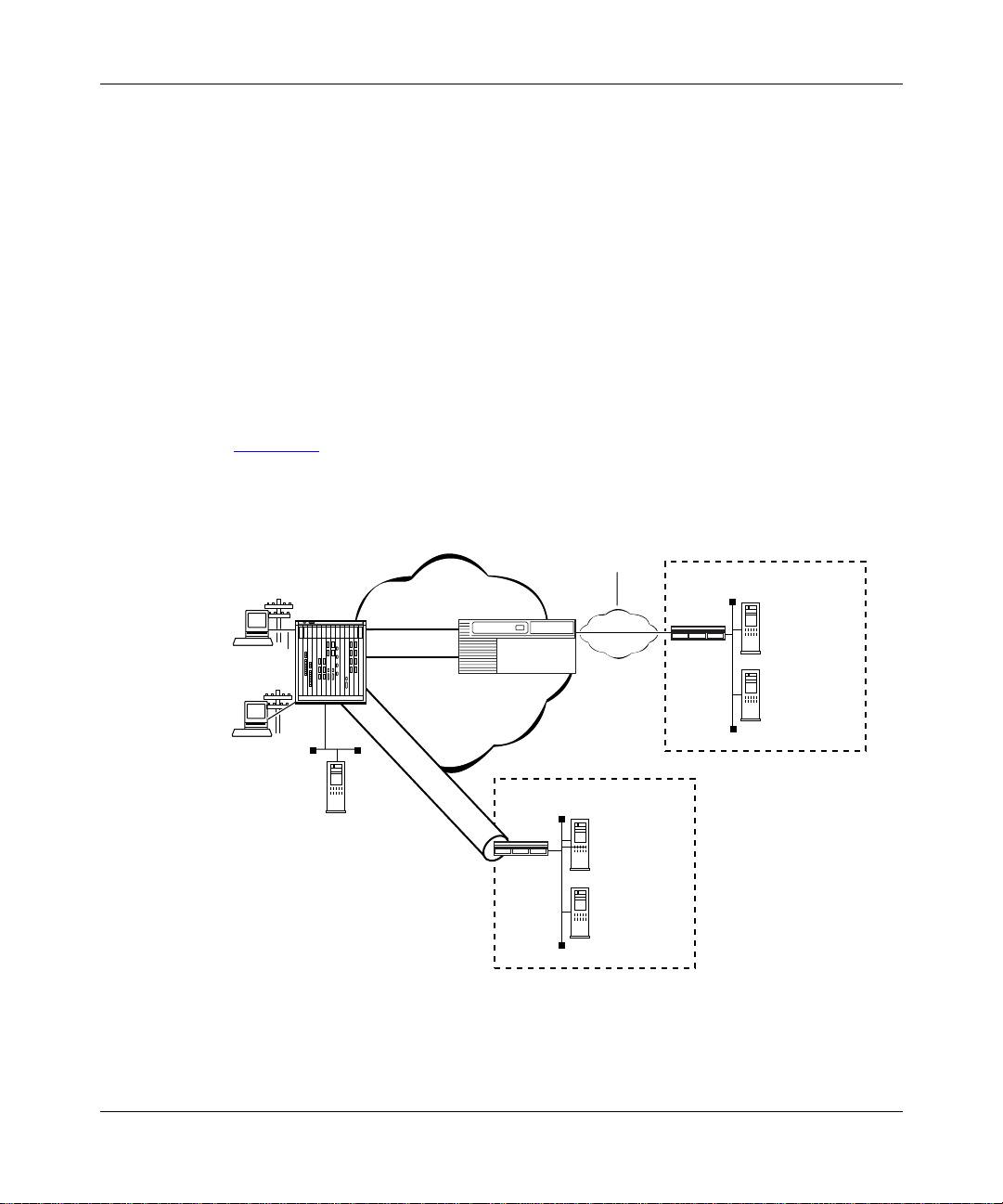
Dial VPN supports both Layer 3 and Layer 2 tunnels on the same ISP network.
Figure 1-1
shows a Dial VPN network with both Layer 3 and Layer 2 (L2TP)
tunnels.
WAN
(PPP or
Frame rela y)
Remote
node
PPP
Remote
node
PPP
RAC
Layer 3 tunnel
IP Network
L2TP tunnel
GW
Customer Premise
Router
Authentication
accounting
Authorization
IP management
Server
Figure 1-1. Dial VPN Network with Layer 3 and Layer 2 Tunnels
308606-14.00 Rev 00
TMS
Customer Premise
Router
Authentication
Accounting
Authorization
IP Management
Server
DVS0017A
1-3
Page 24

Configuring and Troubleshooting Bay Dial VPN Services
Layer 3 Tunneling
In Layer 3 tunneling, the tunnel exists between the Network Access Server
(NAS), which is a Remote Access Concentrator (RAC), and a gateway router.
Both end points of the tunnel are within th e ISP network.
Layer 2 Tunneling
In Layer 2 tunneling, the tunnel exists between the Layer 2 Tunneling Protocol
(L2TP) access concentrator (LAC), usually a remote access concentrator on the
ISP network, and the L2TP network server (LNS), a router or extranet access
switch on the customer’s home network. Rath er than terminating at the remote
access concentrator, the IP tunnel extends the PPP session to the LNS, which acts
as a virtual remote access concentrator.
Note:
In this guide, the term LAC refers to a remote access server with L2TP
capabilities. The term RAS refers to a remote access server without L2TP
capabilities.
Other features of L2TP include using the Internet infrastructure to support
multiple protocols a nd unregistered IP addresses. Be cause the dia l-in user’ s data is
tunneled at Layer 2 and above (in the ISO model), the L2TP protocol is
independent of Layer 3 information. Enterprise customers with unregistered IP
addressing schemes can also use L2TP to reach their home network.
Comparing Layer 3 and Layer 2 Features
Dial VPN supports both Layer 3 and Layer 2 tunneling on the same ISP network.
Both provide secure network access for dial-in users to their home networks.
Table 1-1
Layer 2 tunneling.
1-4
briefly compares the most significant features of both Layer 3 and
308606-14.00 Rev 00
Page 25

Tunneling Overview
Table 1-1. Layer 3 and Layer 2 Dial VPN Feature Implementation
Dial VPN Feature Layer 3 Layer 2
Tunnel management
Protocol Mobile IP L2TP
Encapsulation GRE L2TP
Tunnel end points NAS and gateway LAC and LNS
Dynamic IP address
allocation
Layer 3 protocols
supported
, ACP, or
erpcd
RADIUS (BSAC)
IP pooling or DHCP IP pooling
IP, IPX IP
How a Dial VPN Network Functions
Any authorized remote user (using a PC or dial-up router) who has access to a
phone line and a modem can dial into your network through Dial VPN. A remote
node can be an individual user dialing in or a dial-up router (using IP) through a
public-switched telephone network (PSTN) or an ISDN connection. A remote
user can dial in to a Dial VPN network to connect either to a corporate or home
network or to a third-pa rty ISP. Dial VPN regards these as functionally equival ent.
Figure 1-2
configuration. In reality, a Dial VPN service provider’s network might include
several remote acce ss se rvers to service a va ri ety of dial-in users , wit h both Layer
3 and Layer 2 tunn els s erv ing different types of networks. You can configure Di al
VPN so that its operation is transparent both to users and applications. You may
find it useful to draw a map of your own configuration and label the interfaces
with their IP and, if appropriate, frame relay Data Link Connection Identifier
(DLCI) addresses.
is a simplified illustration of one possible Layer 3 Dial VPN
, ACP, or RADIUS
erpcd
(BSAC)
308606-14.00 Rev 00
1-5
Page 26
Configuring and Troubleshooting Bay Dial VPN Services
Tunnel
domain
Service
provider network
data
Third-party
Internet
service
provider
network
Customer
network
Internet
CPE
CPE
LAN
CPE
Customer
RADIUS
server
Remote
node
PPP
connection
PSTN
Network
access
server (NAS)
TMS /erpcd
server
Gateway
T unnel
Frame relay
or PPP
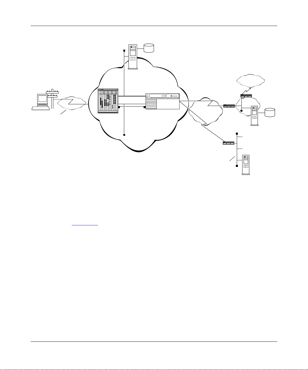
Figure 1-2. Dial VPN Network with Connections to Different Destination Types
Figure 1-2 shows a Dial VPN serv ice provider network wit h a Layer 3 t unnel. The
gateway provides connection services both to a corporate LAN and to a
third-party ISP network. This figure shows only one tunnel, but in reality Dial
VPN creates one tunnel for each dial-in connection.
User
data
Third-party
ISP
RADIUS
server
DVS0012A
In this illustration, a user at a remote node can dial in to a corporate or home
network or a third-party ISP by calling a local phone number associated with that
destination network. The network access server handles the call. The service
provider’s network uses a standard IP connection between the network access
server, shown here as a 5399 module in a 5000 MSX chassis, and the gateway. A
PPP connection or a frame relay PVC and a static route must exist between the
gateway and the customer premise equipment (CPE) router to provide a path for
packets to return to the remote node.
1-6
308606-14.00 Rev 00
Page 27

For Nortel Networks routers used with a Layer 3 Dial VPN tunnel, you must
specify an adjacent host and a static route between the gateway and the CPE, and
also between the CPE router and the remote node. (The adjacent host and static
routes do not appear in this diagram.) For an illustration of Layer 3 tunneling, see
Chapter 3
The rest of this guide describes how to install and configure a Dial VPN service
provider network. It also indicates the requirements for the remote node and the
RADIUS and DHCP servers, with references to the documentation that explains
how to do the configuration.
.
Dial VPN Network Components
Installing and configuring a Dial VPN service provider network involves several
tasks, some of which you may already have completed. You must:
• Plan the network.
• Install and connect the network hardware.
• Install and configure the network software.
Tunneling Overview
• Verify that the elements outside the Dial VPN networ k, specifica lly the
remote server or servers, the router on the home network, and the remote
dial-in nodes, are properly configured.
• Power up, test, and troubleshoot your network.
See the docu mentation for each of these en tities for information on how to install
and configure them.
This guide deals specifically with how you combine these elements into a Bay
Dial VPN network. The following sections summarize the elements of Dial VPN
networks.
Remote Dial-In Nodes
Remote nodes can be PCs (portable hosts) or dial-up routers, using PPP for
dial-up connections. The portable host must have PPP client software and a
TCP/IP or IPX protocol stack loaded.
Dial VPN supports dial-up IP (and, for Layer 3, IPX) over PPP for dial-in PC
clients and IP over PPP for dial-in routers connected to LANs.
308606-14.00 Rev 00
1-7
Page 28

Configuring and Troubleshooting Bay Dial VPN Services
The following considerations apply only to Layer 2 (L2TP) tunnels:
• If the PC or router does not have built-in L2TP software capabilities, it dials
into a LAC, which provi des a tunnel across the Internet to the cor por at e LNS.
This type of connection is the primary focus of this guide.
• If the PC or router is an L2TP client, that is, it has built-in L2TP capability,
the L2TP client software provides a tunnel through a network access server
across the Internet to the corporat e LNS. A LAC is unnecessar y with an L2TP
client.
The main difference between connecting an L2TP client and a nonclient is the
starting point of the tunnel. For an L2TP client, the tunnel begins at the PC or
router; for a non-L2TP client, the tunnel be gins at t he LAC. Al l tunnels end at the
LNS.
ISP Network Components for Layer 3 Tunnels
The devices that make up t he Dial VPN service provider network can be all at the
same site or can be separated by several “hops” within the same network. A
network with Layer 3 Dial VPN tunnels can consist of a network access server
(NAS), a gateway router that serves as the tunnel end point, and a tunnel
management server.
Network Access Server (NAS)
A network access server (NAS) can be a Remote Access Concentrator
Model 8000 or a System 5000 chassis with one or more Model 5399 Remote
Access Concentrator modules . Each module is configur ed with a net work addre ss
belonging to the service provider’s address domain. The Remote Access
Concentrator 8000/5399 includes a dual WAN server, which can support both
analog calls and digital calls carried over ISDN. The NAS receives and processes
calls from remote nodes and routes data to remote nodes.
Note:
This guide uses the term network access server (NAS) to refer to the
device that performs network access functions, such as answering dial-in user
calls, authenticat ing tunne l user s, build ing tunn els, and so on. In the Dial VPN
context, this device is usually a Remote Access Concentrator (RAC). Other
documents may refer to this same device as a remote access server (RAS).
Essentially, all three terms (NAS, RAS, and RAC) refer to functionally the
same device.
1-8
308606-14.00 Rev 00
Page 29

Tunneling Overview
Gateway
Used only in Layer 3 networks, the gateway can be an ASN, BLN, BLN-2, BCN,
or System 5000 MSX equipped with a Model 5380 module running BayRS
software.
The gateway connects the Dial VPN service provider’s network and the CPE
router on the remot e user’s home network. The gateway performs convent ional IP
routing functions configured on interfaces connected to the IP network, through
which the network access servers can be reached.
The gateway is the end point of the IP-routed tunnels that transport packets
originated by remote nodes and encapsulated by the NAS. The gateway also
connects to the CPE router on the user’s home network. The gateway is the data
terminal equipment (DTE) for frame relay PVCs or PPP connections connecting
to multivendor RFC 1490-compliant routers on the customer premises.
For a frame relay network, the connection is through a frame relay user network
interface (UNI). The gateway forwards traffic between a remote node and the
corresponding node in its h ome network by f orward ing pa ckets over a f rame relay
PVC connecting the UNI to the IP tunnel. Thus, the gateway uses the IP tunnel
and the frame relay PVC as two links through which it can send the user traffic
from one side to the other.
With a frame relay connection, you can also configure up to 10 secondary
gateways for use as backup gateways or as a load-balancing mechanism.
The PPP connection between the gateway and the customer’s home network
functions in a similar way, except that the connection is through a PPP interface
instead of a frame relay interface.
The gateway may also act as a RADIUS client to authenticate the remote user
based on information provi ded from the NAS. The RADIUS client on the gateway
sends an authentication request to the RADIUS server on the home network,
which either grants or denies the request in a message to the gateway. The
gateway the n returns this information to the NAS to continue the proc ess.
308606-14.00 Rev 00
1-9
Page 30

Configuring and Troubleshooting Bay Dial VPN Services
Tunnel Management Server (TMS)
The mechanism for identifying tunneled users is the tunnel management server
(TMS) that resides on a tunnel management server.
For Layer 3 tunnels, the NAS re tr ieves t he tunne l confi gurat ion a ttri butes f rom its
TMS database residing o n t he t unnel management server and uses them to build a
tunnel into the customer’s network. Once the tunnel is open, the user can be
authenticated at the customer’s network. Tunnel management can be either
RADIUS or erpcd-based.
• In the RADIUS method, a RADIUS server resid es at the service provider site
and manages the TMS database. The NAS and the RADIUS server
communicate using IP over the service provider network. Backup gateways
and load distribution mode require the use of the RADIUS method.
•In the erpcd-based method, the TMS hosts a datab ase appl ic ati on (the Tunnel
Management System) that controls the IP tunnel establishment attempt from
the NAS. The TMS runs on the same UNIX host as the Access Control
Protocol (ACP) software. The NAS and the TMS communicate using the
Nortel Networks proprietary Expedited Remote Procedure Call Daemon
(erpcd or Secure erpc d). Both Layer 3 and Layer 2 tunnels can use this
method.
In either method, the NAS queries the TMS database for the addressing
information it needs to construct the IP tunnel. This query is based on the user
domain name and on the policy and state information of the enterprise customer
account when the r emot e u ser di al s in. As a Dial VPN network administrator, you
must provide the user domain and tunnel addressing information to the TMS
database for each enterprise customer. Chapter 5
commands you can use to provision the default TMS database.
ISP Network Components for Layer 2 Tunnels
The following sections describe the components of a network with Layer 2
tunnels. A network with Layer 2 Dial VPN tunnels also has a NAS (which may
function as either a LAC or a RAS) and a tunnel management server. The edge
router, however, doe s not function as a ga tewa y; ra ther, the t unne l end point is the
CPE router on the customer’s home network. The network itself can have
additional components. Thi s descr iptio n pertains only to tho se rele vant to Lay er 2
tunneling.
1-10
and Chapter 6 describe the
308606-14.00 Rev 00
Page 31

Tunneling Overview
L2TP Access Concentrator (LAC)
The L2TP access concentrator (LAC) resides at the ISP network. The LAC
establishes the L2TP tunnel between itself and the LNS. When the remote user
places a call to the ISP network, the call goes to the LAC. The LAC then
negotiates the act ivat ion o f an L2TP tunn el with the LNS. Thi s tunne l carr ies dat a
from the remote user to the corporate network.
For more information about the Nortel Networks implementation of the LAC in
an L2TP network, refer to Configuring L2TP Services.
Remote Access Server (RAS)
The remote access server (RAS) resides at the ISP network. If the remote host is
an L2TP client, the tunnel is established from the remote client through a RAS to
an LNS at the corporate n etwork. In t his situation, there is no need for a LAC .
The RAS does not establish the tunnel; it only forwards already tunneled data to
the destination.
Tunnel Management Server (TMS)
The ISP network must have a mechanism for identifying L2TP tunneled users so
that the LAC can construct the L2TP tun nel. Dial VPN uses a mech anism cal led a
tunnel management server (TMS); ot her vend ors may use a dif fe rent met hod. The
TMS has the same function as for Layer 3 tunnels.
Customer/Home/Internet Service Provider Network
The Dial VPN network int er ac ts wit h the customer premis e e qui pment ( C PE) and
the RADIUS authentication server and the RADIUS accounting server on the
customer’s destination network.
Customer Premise Equipment (CPE)
The CPE is a r outer or extranet switch that connects to the Dial VPN networ k by
means of frame relay PVCs or a PPP connection. The CPE routes traffic from the
remote nodes to hosts on the home network and from the home network hosts
back to remote nodes.
308606-14.00 Rev 00
1-11
Page 32

Configuring and Troubleshooting Bay Dial VPN Services
Enterprise subscribers of this service must configure the CPE router to allow
routing to occur between the remote nodes and the hosts on the home network.
For a Layer 3 frame relay circuit, a frame relay PVC, a static route, and (for a
Nortel Networks or other non-Cisco router), adjacent host designation must exist
between the CPE and the gateway router on the Dial VPN network. For frame
relay, all Dial VPN circuits must be in the same service record. PPP circuits have
similar requirements, except for the PVC and service record.
L2TP Network Server (LNS)
The L2TP network server (LNS) is a router that resides at the customer’s home
network and serves as the termination point for Layer 2 (L2TP) tunnels and
sessions.
The LNS authenticates PPP connection requests and allows end-to-end PPP
tunneled connections. An LNS may also work in conjunction with a RADIUS
server to authenticate dial-in users.
An LNS can accommodate multiple users, each with his or her own L2TP session.
The L2TP session is the virtu al e nd-t o- end connection over which the LAC sends
data to the LNS.
In Layer 2 tunneling, the CPE router is also the LNS. For m or e in for m at ion about
the Nortel Networks LNS, see Configuring L2TP Services.
RADIUS Authentication Server
The RADIUS authenticati on server on the c ustomer’ s net work is a network access
security system. It uses a locally stored and maintained database that contains all
user authentica ti on and network service a cce ss information to auth enticate dial-in
user access requests.
Note:
The Dial VPN RADIUS server for Layer 3 tunnels must be on a
separate physical device from any RADIUS server for Layer 2 tunnels or for
switched services. The RADIUS server for Layer 2 tunnels can be the same
physical device as for any dial services RADIUS server.
1-12
308606-14.00 Rev 00
Page 33

Tunneling Overview
The RADIUS server has three main functions in a Dial VPN L2TP network:
• Authenticating remote users
• Assigning IP addresses to remote users
• Providing accounting services for corporate billing
For Layer 3 tunnels, the RADIUS client of this server resides on the gateway.
The RADIUS client on the ISP network generates a RADIUS authentication
request to the appropriate RADIUS server. This request contains the user
authentication information. The CPE receives the authentication request and
forwards it to the RADIUS server.
Once the user is authenticated, the RADIUS server grants access to the remote
node by returning an authentication accept packet with RADIUS authorization
information to the gateway through the CPE.
For a Layer 3 tunnel, the gateway then forwards the user authentication to the
NAS, which initiates an IP tunnel to the gateway using Mobile IP protocol
mechanisms.
For an L2TP tunnel, the RADIUS server database centralizes the authentication
function, eliminating the need to configure each LNS with user names and
passwords. It also assigns an IP addres s to the re mote hos t to identi fy the hos t and
ensure that it is part of its own subnet.
For more information about the Nortel Networks implementation of RADIUS
user authentication and accounting, see Configuring RADIUS and the BaySecure
Access Control Administration Guide.
RADIUS Accounting Server
The RADIUS accounting server tracks when users start and end their dial-in
connections and acquires statistics about each session. BaySecure Access
Control™ fully supports RADIUS accounting and provides the network access
server with RADIUS accounti ng information for every a ct ive dial-in session. The
RADIUS accounting server can provide accounting services for the corporate
network, calculating billing charges. For a full description of BaySecure Access
Control and the RADIUS funct ions it supports, see the BaySecure Acce ss Co ntrol
Administration Guide.
308606-14.00 Rev 00
1-13
Page 34

Configuring and Troubleshooting Bay Dial VPN Services
DHCP Server
If you implement the optiona l Dynamic Host Confi guratio n Protocol ( DHCP) as a
way of dynamically assigning IP addresses to dial-in users, you must also
configure a DHCP server on t he cust omer’ s ne twork. For a deta iled d escri ption o f
using DHCP, see Chapter 8
in this guide.
Additional Planning Information
Appendix A contains a network planning worksheet that you can use in
determining how to configure the BayRS side of your Dial VPN network. You
may not have enough informati on yet to complete this worksheet , but if you fill it
in as you go along, it can provide documentation for your network. You may also
find this information useful when changing or troubleshooting your network.
Where to Go Next
For a description of how a packet moves through a Dial VPN network and other
background information that can help you visualize the data flow through the
network, go to Chapter 2
for Layer 2 tunneling or Chap ter 3 for Layer 3 tunneling.
For information about configuring Dial VPN, go to Chapter 4
For troubleshooting information, go to Appendix C, “Troubleshooting
For configuration tips and techniques, go to Appendix D, “Tips and Techniques
1-14
.
.”
.”
308606-14.00 Rev 00
Page 35

Chapter 2
Dial VPN Layer 2 Tunneling
This chapter describes how a Layer2 Dial VPN tunnel functions. Among these
concepts are h ow a d ata packet sent fr om a r emote node u sing PPP moves thr ough
a Dial VPN service provider’s network to a corporate or “home” network via a
frame relay or PPP connection. It also explains how the Dial VPN tunnel forms a
path to move data q uickly and ef f icie ntly t o and f rom th e remote node t hrough the
Dial VPN service provider’s IP backbone network.
Dial VPN uses encapsulation technologies and the Layer 2 Tunneling Protocol
(L2TP) to provide a secure pathway for remote users to exchange data with their
corporate home net work . Regard le ss of where a remote nod e is locat ed, it ca n dial
in to its Dial VPN service provider and connect to the home network.
Figure 2-1
an L2TP access concentrator (LAC) and the other tunnel end point is the CPE
router or extranet switch on t he customer’ s home ne twork. That router or switch is
the L2TP network server (LNS), which terminates all L2TP tunnels and sessions
with that ne twork. In this figure, the dotted line shows the pa th of the packet
through the tunnel; the Dial VPN service provider network is the ISP network.
308606-14.00 Rev 00
shows the path of a packet in a Layer 2 tunnel. The NAS functions as
2-1
Page 36

Configuring and Troubleshooting Bay Dial VPN Services
ISP network
Frame rela y
Remote
host
PC
No L2TP
functionality
PPP
connection
LAC
T unnel
Data
TMS
connection
Figure 2-1. Layer 2 Tunnel Packet Path
Note:
If the dial-in node is configured with an L2TP client, that client serves
as the LAC, and the RAC serves the function of a normal network access
server. In this guide, most of the descriptions use the Remote Access
Concentrator as the LAC for Layer 2 tunnels.
Building a Network for Layer 2 Tunneling
The steps that follow provide a suggested order for configuring your network for
Dial VPN Layer 2 tunneling. For detailed information about each of these steps,
see Chapters 4 through 10.
Corporate network
LNS
RADIUS
server
At the ISP network, configure the following:
1.
• Remote Access Concentrator, serving as the L2TP access concentrator
(LAC)
• Tunnel management server (TMS) on the erpcd server for the
erpcd-bas ed solution
• Access Control Protocol (A CP) server (only for the erpcd-based solution)
• Edge router capable of connecting to the LNS on the customer’s home
network with frame relay or PPP
2-2
308606-14.00 Rev 00
Page 37

Dial VPN Layer 2 Tunneling
Install and configure any intermediate nodes on the WAN.
2.
The WAN can include intermediate nodes. For installation and startup
information, refer to the hardware documentation for each device.
Install the software for the tunnel management server, Remote Access
3.
Concentrator, and (for the
-based solution) Acce ss Contr o l Pr otocol
erpcd
on the host that serves as the load host for the Remote Access
Concentrator.
For installation instructions, see the Remote Access Concentrator
documentation.
Load the operating software onto the Remote Access Concentrator and
4.
boot the Remote Access Concentrator.
For detailed descriptions of the boot procedures, see the Remote Access
Concentrator documentation.
Configure the Remote Access Concentrator software, as described in
5.
Chapter 4
, to handle PPP dial-in calls from remote nodes, determine
whether they are tunnel clients, and route them appropriately.
Configure the TMS (including the authentication type) by adding an
6.
entry in the TMS for each domain in the TMS database. See Chapter 5
and Chapter 6
for more information.
When configuring the TMS, you can choose either local or remote
authentication. Dial VPN uses a RADIUS server on the customer’s home
network to provide authentication and assign IP addresses.
For DHCP address allocation, confi gure the TMS with the DHCP paramete rs,
as described in Chapter 5
Establish a connection between the edge r outer on the Dia l VPN network
7.
.
and a CPE router (the LNS) on the home network using frame relay or
PPP.
308606-14.00 Rev 00
2-3
Page 38

Configuring and Troubleshooting Bay Dial VPN Services
Make sure that the home network is configured to connect to the Dial
8.
VPN network.
Specifically, ensure that:
• The RADIUS server on the home network is configured to work with the
RADIUS client on the Dial VPN network. If dynamic IP address
allocation or DHCP is enabled, the RADIUS or DHCP server must have
an allocated pool of addresses for authenticated dial-in users and have
RADIUS accounting enabled.
• The CPE router that is the end point of Layer 2 tunnels is configured as
the LNS and is configured with a frame relay or PPP connection to the
ISP network (including a static route and an adjacent host if the CPE
router is not a Cisco device).
For instructions on configuring the LNS, see Configuring L2TP Services.
• Any shared informat ion, suc h as pa sswo rds, “secr ets,” or phon e nu mbers,
is consistent across the link.
Individually test each network component, then test the entire system.
9.
L2TP Packet Encapsulation
The dial-in user sends PPP packets to the LAC, which encapsulates these
incoming packets in an L2TP packet and sends it across an IP network through a
bidirectional tu nne l . After the LNS receives the packets, it decapsulates them and
terminates the PPP connection.
Figure 2-2
2-4
shows how data is encapsulated for transmission over an L2TP tunnel.
308606-14.00 Rev 00
Page 39

Dial VPN Layer 2 Tunneling
Remote user places a call
PPP IP
Layer 2
protocol
IP/UDP
IP DATA
Data packet moves to the corporate network
LAC
LNS
DATA
PPP
IPL2TP
DATA
L2T0005A
Figure 2-2. L2TP Packet Encapsulation Process
Nortel Networks L2TP Implementation
In an L2TP tunnel, the Nortel Networks router or extranet switch on the home
network is the LNS. LNS software operates on the BLN, BCN, and ASN
platforms.
The Nortel Networks LNS has the following characteristics:
• Each slot can act as an LNS, wh ich means that one rout er can have many LNS
interfaces, each with its own address. You can have as many LNS interfaces
as there are available slots on the router.
308606-14.00 Rev 00
2-5
Page 40

Configuring and Troubleshooting Bay Dial VPN Services
• The LNS performs user authentication with a RADIUS server to prevent
unauthorized users from accessing the network.
• The LNS accepts only incoming calls; it does not place calls to the LAC.
• The Nortel Networks L2TP implementation supports only IP traffic through
the L2TP tunnel. The LNS supports only numbered IP addresses.
• The router interface between the ISP and the home network (see Figure 2-4
a leased line operating with frame relay or PPP (including PPP multilink).
Nortel Networks recommends that you use a high-speed link, such as T1, for
the leased connection.
• The LNS terminates PPP multilink and PPP encapsulated data within an
L2TP packet.
• The LNS operates with the LAC implementation configured on the Nortel
Networks Model 8000/5399 Remote Access Concentrator.
• The host (PC or router) dialing into the ISP network can be on the same
subnet as the IP interface on the LNS.
• The LNS supports RIP. RIP is particularly useful when the remote host is a
router, because it enables the LNS to learn routing information from the
remote router.
For a summary of how to configure the LNS, see Chapter 8
complete instructions on how to configure a Nortel Networks router as an LNS,
see Configuring L2TP Services.
Tunnel Management in L2TP Tunnels
) is
of this guide. For
The Nortel Networks tunnel management server (TMS), which resides at the ISP
network, stores the TMS database. This database contains the remote users’
domain name, the IP address information of each LNS, and other tunnel
addressing information that the network administrator configures. The LAC
requests this information from the TMS to construct the L2TP tunnel.
2-6
308606-14.00 Rev 00
Page 41

When the LAC receives a call, it forwards the domain name to the TMS. The
domain name is the portion of the user’s address that specifies a particular
location in the network. For examp le , i f the user name is j doe@a bc.c om, abc.com
is the domain name. The TMS looks up the domain name and verifies that the
remote user is an L2TP u ser. The TMS also provides the LAC with t he addres sin g
information required to establish a tunnel to the correct LNS.
Note:
The domain name referred to in this guide is a domain identifier that
does not follow a specific format. It is not related to any Domain Name System
(DNS) protocol requirements.
Security in an L2TP Network
You can configure two layers of security in an L2TP network:
• Tunnel authentication
Tunnel authentication is the process of negotiating the establishment of a
tunnel between the LAC and the LNS.
Dial VPN Layer 2 Tunneling
• User authe ntication
The network administrator at the corporate site can configure a RADIUS
server with the names and passwords of authorized users. The server’s
database centralizes the authentication function, eliminating the need to
configure each LNS with user names and passwords.
When the LNS receives a call, it forwards the user information to the
RADIUS server, which verifies whether the user is authorized to access the
network.
You can also configure the LNS to perform user authentication if a RADIUS
server is not part of the network configuration.
The following paragraphs de scri be the No rtel Networks imp lementa tion of tunnel
and user authentication.
Tunnel Authentic ation
For Dial VPN Layer 2 tunnel security purposes, you must enable the LNS to
perform tu nnel aut henti cation. Tunnel aut henti ca tion is the proce ss of negot iati ng
the establishment of a tunnel.
308606-14.00 Rev 00
2-7
Page 42

Configuring and Troubleshooting Bay Dial VPN Services
During tunn el authentication, the LNS identifies the L2TP client or LAC by
comparing the LAC’s tunnel authentication password with its own password. If
the passwords match, the LNS permits the LAC to establish a tunnel.
The LAC does not send the tunnel authentication password as a plain-text
message. The exchange of passwords works much like the PPP Challenge
Handshake Authenticati on Protoc ol (CHAP). Whe n one side re ceives a challenge ,
it responds with a value that is calculated based on the authentication password.
The receiving side matches the value against its own calculation. If the values
match, authentication is successful.
Tunnel authentication occurs in both directions, which means that the LAC and
LNS both try to verify the other’s identity.
You can enable tunnel authentication on the Nortel Networks LNS. If tunnel
authentication is dis abl ed, which is the defaul t, t he LNS se nds a default challenge
response to the LAC during the authentication process so that the tunnel can be
established. The LNS cannot send outgoing calls, so it cannot initiate tunnel
authentication.
During tunnel authentication, the following exchange of messages takes place:
1.
The LAC sends a tunnel setup message, called the start control connection
request (SCCRQ) message to the LNS. This message includes a challenge to
the LNS.
2.
The LNS replies with a tunnel response, a challenge response, and its own
challenge message. This is called the start control connection reply (SCCRP)
message.
3.
The LAC replies with a challenge response that includes its tunnel
authentication password. This is the start control connection connected
(SCCCN) message.
4.
If this same password is configured for the LNS, the LNS grants approval to
the LAC to establish a tunne l.
Figure 2-3
2-8
shows tunnel authentication and the control messages.
308606-14.00 Rev 00
Page 43

Dial VPN Layer 2 Tunneling
ISP network
LAC
SCCRQ
tunnel request and challenge
SCCCN
challenge response
Figure 2-3. Tunnel Authentication Control Messages
After tunnel authentication is complete, it need not be repeated for other calls to
the same LAC.
RADIUS User Authentication
Corporate network
PPP connection
LNS
SCCRP
tunnel response, challenge response,
and LNS challenge
L2T0006A
RADIUS user authentication is enabled by default on the Nortel Networks LNS;
you must configure this feature so that the LNS can validate the remote user’s
identity before allowing access to the network.
The network administrator at the corporate site must configure a RADIUS server
with the names and pa ss words of authorized users. When the LNS receives a call,
it forwards an authentication request with the user information to the RADIUS
server, which verifies whether the user is authorized. If the user is permitted
access to the network, the RADIUS server replies with an acknowledgment
message and th e appropriate IP address information for that user to make a
connection.
For more information about configuring Nortel Networks routers as RADIUS
servers, see Configuring RADIUS.
308606-14.00 Rev 00
2-9
Page 44

Configuring and Troubleshooting Bay Dial VPN Services
RADIUS Accounting
The RADIUS server can provide accounting services in addition to its
authentication services. RADIUS accounting is enabled by default on the Nortel
Networks LNS.
The RADIUS accounting server calculates billing charges for an L2TP session
between the remote user and the LNS. To determine these char ges, t he serv er use s
information that it receives from the LNS, such as the status of each call and the
number of packets sent during the session. Using this data, the RADIUS server
determines billing charges, which the network administrator can use to manage
network costs.
The primary RADIUS accounting server can be the same server as the
authentication server or it can be a different server.
For more information about RADIUS accounting, refer to Configuring RADIUS.
L2TP IP Interface Addresses
When configuring the Nortel Networks LNS, you must configure an IP address
for every slot that has an L2TP interface. This address is referred to as the L2TP
IP interface address. The L2TP IP interface can be any valid IP address.
The L2TP IP interface address is internal to the LNS. When communicating with
the remote user , the L NS associat es the user’ s IP address , which is as signed by the
RADIUS server, with the L2TP IP interface address that you configured.
The L2TP IP interface address and the RADIUS-assigned IP address do not have
to be in the same subnet.
2-10
308606-14.00 Rev 00
Page 45

Remote Router Configuration
If the host at the remote site is a Nortel Networks router, you may need to
configure a dial-on-demand circuit for the remote router’s dial-up interface to the
LAC at the ISP network.
Enable RIP on both the dial-on- de mand ci rc uit and t he at tached LAN interface of
the remote router, so that the LNS can learn routing information from the remote
router. To avoid unnecessarily activating the circuit because of RIP packets,
enable dial-optimized routing for the dial-on-demand circuit.
In addition, confi gure a de fault o r stati c route f or th e remote rout er , whi ch uses the
next-hop address that corresponds to the L2TP IP interface address of the LNS.
This default or static route enables the remote router to deliver L2TP packets to
the LNS.
Starting an L2TP Ses sion
The connection process for Layer 2 tunnels is similar to that for Layer 3, but the
end points of the tu nnels are dif ferent. In L2TP t unneling , the end po int of t he PPP
connection from a LAC or a remote access server (RAS) extends to an L2TP
network server (LNS). Multiple users can communicate through a single tunnel
between the same LAC and LNS pair. Each user transmits and receives data i n an
individual L2TP session.
Dial VPN Layer 2 Tunneling
Packets flo w across an L 2TP tunnel during an L2TP session. An L2TP session is
created when an end-to-end WAN connection is established between the remote
host and the LNS.
The L2TP portion of the packets sent through the tunnel contains a header with a
call ID field (also called a session ID) and a tunnel ID field. The call ID field,
which indicates t he sess ion that the WAN packet belongs to, is negot iated b etween
the LAC and the LNS when the L2TP call is set up. The tunnel ID specifies the
tunnel that the L2TP session is using.
In addition to the fields in the header, the L2TP packet contains a call serial
number, which is a unique number for each L2TP call. This number matches the
call to the L2TP session.
308606-14.00 Rev 00
2-11
Page 46

Configuring and Troubleshooting Bay Dial VPN Services
Examples of L2TP Tunnels
Figure 2-4 shows an L2TP network that uses a LAC to connect to the LNS. The
tunnel is between the LAC and the LNS.
ISP network
Remote
host
PC
No L2TP
functionality
PPP
connection
LAC
T unnel
Data
TMS
Figure 2-4. L2TP Network Using a LAC
Figure 2-5 shows an L2TP network that uses a RAS to connect to the LNS. The
tunnel is between the PC (the L2TP client) and the LNS.
ISP network
Remote
host
PC
T unnel
RAS
Data
Frame rela y
connection
Frame rela y
connection
Corporate network
LNS
RADIUS
server
L2T0003A
Corporate network
LNS
L2TP
client
Figure 2-5. L2TP Network Using a RAS
2-12
RADIUS
server
L2T0004A
308606-14.00 Rev 00
Page 47

Dial VPN Layer 2 Tunneling
Making a Connection Acros s an L2TP Network
The following steps explain how a remote user connects across an L2TP network
that includes a Nortel Networks LAC, TMS, and LNS. (See Figure 2-4
1.
The remote user dials a LAC at the local ISP network to establish a PPP
connection to the corporate network.
In the call, the user includes any required information, for example, a user
name, including a domain name and a password. When dialing in, the user
enters a name, for example, jdoe@abc.com; jdoe is the user name and
abc.com is the domain name.
2.
The LAC receives the call and passes the domain name to the TMS.
If the TMS finds a match for the domain name, a tunnel can be created. The
TMS also checks the number of current connections so that they will not
exceed the maximum number allowed.
If the user is not a tunnel candidate, as determined by the domain name, the
LAC assumes that the remote host is making a regular dial-in request and
authenticates the user accordingly.
.)
3.
4.
5.
308606-14.00 Rev 00
The LAC tries to establish an L2TP tunnel with the LNS.
For the LAC to send a tunnel request to the LNS, it needs the address of the
LNS. The LAC requests the address from the TMS. It then checks for this
address in its own rout in g t abl e. Af ter obt ai ni ng t he a ddr ess , the LAC sends a
tunnel request to the LNS. The LNS may perform tunnel authentication, if
configured to do so. If the LAC and LNS complete tunnel authentication
successfully, the LAC establishes the tunnel.
After the tunnel is established, the LAC forwards the remote user’s name to
the LNS, which verifies the user’ s identit y with the corpora te RADIUS server .
If the RADIUS server recognizes the user name, it replies with an
acknowledgment and an IP address that it assigns to the remote user fo r the
duration of the call. This IP address identifies the remote user who may not
have an address of his own.
After the remote user i s succ essfu ll y auth entic ate d, the user h as an e nd- to-en d
PPP connection to the corporate network over the Internet.
The tunnel can now carry a user session during which the LAC and the LNS
exchange PPP packets.
2-13
Page 48

Configuring and Troubleshooting Bay Dial VPN Services
When Does Dial VPN Tear Down the Tunnel?
The LAC brings down the tunnel for any one of the following reasons:
• A network failure occurs.
• The LAC or other equipment at the ISP is not operating properly. If the LAC
fails, all tunnel users are disconnected.
• There are no active sessions inside the tunnel.
An individual session ends when a remote user disconnects the call, but
multiple sessions can run inside a single tunnel.
• The system administrator at the ISP terminates the user connection.
• The LAC is not responding to a Hello packet from the LNS.
For the LAC to reestablish a tunnel, the remote user must place a new call.
If the LAC fails, all tunnel users are disconnected and the active user counts are
decremented. However, there is no quick way to determine when a LAC fai ls. The
logging connection may not be reset until after new tunnel users have connected.
When a LAC starts, one of the first things it does is open its ACP-logging
connection. When a new logging connection opens, TMS decrements the
appropriate counts for each d omain that had a user connected to the LAC. If this i s
the first time the LAC has come up, then ther e will be nothing to decrement.
Note:
If you enter the
reset security
a connection with the LAC causes the maximum number of users count to
decrement, even though users with existing connections are still connected.
This means that the maximum numbe r of users count may be exceeded. As
users with existing connections disconnect, the count will synchronize and
correspond to the actual number of users connected.
If the TMS fails, a LAC can detect the failure through the failure of the logging
connection. The LAC falls back to secondary servers, if any. Unless the database
is shared by the TMS servers, the count of current users is lost.
If the TMS database runs out of disk space while tms_dbm is running, the user
sees an error message. The error message may not state what caused the error. If
there is a shortage of disk space and erpcd cannot create a lock file or add a LAC
to the TMS database, TMS generates a sys log message and the use r cannot make a
connection to the LAC.
2-14
command, a new user who t ri es to make
308606-14.00 Rev 00
Page 49

Chapter 3
Dial VPN Layer 3 Tunneling
This chapter describes how a Layer 3 Dial VPN tunnel functions. Among these
concepts are how a data packet sent from a remote node using the point-to-point
protocol (PPP) moves through a Dial VPN service provider’s network to a
corporate or “home” networ k via a frame relay or PPP connec tion. It al so explai ns
how the Dial VPN tunnel form s a pat h to move dat a quic kly and e f fici ently to and
from the remote node through the Dial VPN service provider’s IP backbone
network.
Dial VPN uses the Generi c Routing Encapsu lation (GRE) proto col and the Mob ile
IP protocol to provide a secure pathway for remote users to exchange data with
their corporate home networ k over a Layer 3 tunnel. Regardl ess of where a remote
node is located, it can dial in to its Dial VPN service provider and connect to the
home network.
For example, Figure 3-1
from the NAS, through the Layer 3 tunnel to the gateway, across a frame relay
connection, and on to the home network. In this figure, the dotted line shows the
path of the packet through the tunnel; the Dial VPN service provider network is
the ISP network.
308606-14.00 Rev 00
shows how a packet moves in an erpcd-based network
3-1
Page 50

Configuring and Troubleshooting Bay Dial VPN Services
BayD VS service
provider network
PPP
connection
Remote
node
NAS
T unnel
Data
Tunnel
management
server/ACP server
Gateway
Figure 3-1. Layer 3 Tunnel Packet Path
Building a Network for Layer 3 Tunneling
Frame rela y
connection
Corporate
"home"
network
The steps that follow suggest an order for configuring your network. For detailed
information about each of these steps, see Chapters 4 through 9.
At the ISP network, configure the following:
1.
• Remote Access Concentrator, serving as the network access server ( NAS )
• Tunnel Management Server (TMS), either on the UNIX erpcd server for
the erpcd-based solution or on the service provider network RADIUS
server for the all-RADIUS solution
• Access Control Protocol (A CP) server (only for the erpcd-based solution)
• Nortel Networks router that serves as the gateway to the remote user’s
home network
3-2
308606-14.00 Rev 00
Page 51

Dial VPN Layer 3 Tunneling
Install and configure any intermediate nodes on the WAN.
2.
The WAN can include intermediate nodes. For installation and startup
information, refer to the hardware documentation for each device.
Install the software for the tunnel management server, Remote Access
3.
Concentrator, and (for the
-based solution) the Access Control
erpcd
Protocol on the UNIX host that serves as the load host for the Remote
Access Concentrator.
For installation information, see the Remote Access Concentrator
documentation.
Load the operating software onto the Remote Access Concentrator from
4.
the UNIX load host and boot the Remote Access Concentrator.
For detailed descriptions of the boot procedures, refer to the Remote Access
Concentrator documentation.
Configure the Remote Access Concentrator software, as described in
5.
Chapter 4
, to handle PPP dial-in calls from remote nodes, determine
whether they are tunnel clients, and route them appropriately.
For the all-RADIUS solution, install and configure the RADIUS server
6.
on the service provider network to support the TMS database.
For more information about installing and configuring RADIUS servers on
the ISP network, see Chapter 6
Configure the TMS (including the authentication type) by adding an
7.
.
entry in the TMS for each domain in the TMS database. Refer to
Chapter 5
and Chapter 6 for more information.
When configuring the TMS, you can choose either local or remote
authentication. For both the erpcd-based and the all-RADIUS solutions, Dial
VPN uses remote authentication; that is, a RADIUS server on the customer’s
home network provides authentication and assigns IP addresses.
For DHCP address allocation, confi gure the TMS with the DHCP paramete rs,
as described in Chapter 5
.
308606-14.00 Rev 00
3-3
Page 52

Configuring and Troubleshooting Bay Dial VPN Services
Configure the gat eway , includin g the RADIUS client, using Site Manager,
8.
then boot the gateway.
Configure the gateway with an IP connection to the Dial VPN network and a
frame relay or PPP connection to the CPE router on the remote user’s home
network. Configure a RADIUS client on the gateway. For information on
configuring the gateway, see Chapter 7
Establish a connection betwe en a gate way on the ISP network and a CPE
9.
router on the home network using frame relay or PPP.
Make sure that the home network is configured to connect to the Dial
10.
VPN network.
Specifically, ensure that:
• The RADIUS server on the home network is configured to work with the
RADIUS client on the Dial VPN network. If dynamic IP address
allocation or DHCP is enabled, the RADI US or DHCP server must hav e a
pool of addresses al located for a uthenticate d dial-in use rs. For dynamic IP
address allocation, you must have RADIUS accounting enabled.
• The CPE router i s conf ig ured with a frame r el ay or PPP connection to the
Dial VPN gateway (including a static route and an adjacent host if the
CPE router is not a Cisco device), and a separate but similar frame relay
or PPP connection to the RADIUS client on the gateway.
.
• Any shared informat ion, suc h as pa sswo rds, “secr ets,” or phon e nu mbers,
is consistent across the link.
Note: The Dial VPN RADIUS server for Layer 3 tunnels must be on a
separate physical device from any RADIUS server for Layer 2 tunnels or for
dial services. The RADIUS server for Layer 2 tunnels can be the same
physical device as any dial services RADIUS server.
Individually test each network component, then test the entire system.
11.
3-4
308606-14.00 Rev 00
Page 53

How Tunnel Management Works
Tunnel management operates differently on erpcd-based and RADIUS-only
networks, but the end result is the same.
Tunnel Management in an erpcd-Based Network
For an erpcd-based network, the tunnel management server (TMS) runs on the
same host as the Remote Access Concentrator (erpcd) and Access Control
Protocol (ACP) software. T he TMS verifies that the use r at the remote node is a
Dial VPN user . I f the domain portion of the user n ame exists in the TMS data base,
ACP increases the number of current users by one and sends a Grant message to
the NAS. The Grant message contains the tunnel addressing information needed
to send a packet from the remote node to the home network.
The Grant message contains the following information, which is stored in the
TMS database:
• Remote node’s domain name
Dial VPN Layer 3 Tunneling
• Domain name information server (DNIS) -- for Model 8000/5399 platforms,
the DNIS is the called number; for other platforms, it is 0 (zero)
Note:
The default value for the DNIS is 0. The NAS administrator can change
this value.
• Home agent’s IP address on the gateway (the IP address of the gate way end of
the IP tunnel)
• Current number of users
• T ype of con nection bet ween the ISP net work’s edge router or gateway and the
CPE router on the remote node’s home network
• Primary and secondary RADIUS server IP addresses
• Authentication protocol information
For each tunnel user, the NAS sends this information to the RADIUS client on the
gateway, which in turn sends an authentication and address request to the
RADIUS server on the remote node’s home network. When the RADIUS server
responds, authenticating the user, the NAS establishes the tunnel.
308606-14.00 Rev 00
3-5
Page 54

Configuring and Troubleshooting Bay Dial VPN Services
Tunnel Management in an All-RADIUS Network
The all-RADIUS solution integrates the TMS database functions into the
RADIUS server that resides on the service provider network. This RADIUS
server recognizes the format of the VPN identifier in the user name and returns
tunnel information to the NAS. The NAS uses the tunnel information to establish
a connection to th e gateway. Once the connection is made, t he user authentication
information is forwarded to the indicated authentication server.
Refer to Chapter 5
for more information about th e contents of the TMS database.
How the TMS Database Works
The TMS database (by default, UNIX ndbm) resides on the tunnel management
server , which res ides on the ser vice prov ider’ s netwo rk. The main functi on of this
database is to verif y t he u ser na me (or doma in) in formation supplied by th e NAS.
It also supp l ies the NAS w i th the tunnel addressin g information (in the Grant
message) that it needs to create a tunnel for a remote user. The Dial VPN
administrator enters the domain information and the tunnel addressing
information into the database as part of the TMS configuration process.
When the TMS receives a lookup request from the NAS, it parses the user name
into the user and domain name and DNIS, and creates a Domain/0 or
Domain/DNIS key. The TMS database uses this key to find a match in the
database with the supplied user name. If the key matches an existing entry, the
TMS checks to make sure that the maximum number of users is less than the
configured maximum. If so, th e TMS sends a Gr ant message indi cati ng tha t t his i s
a Dial VPN user. The Grant message contains the tunnel addressing information.
3-6
308606-14.00 Rev 00
Page 55

Since ndbm does not have a locking feature, Nortel Networks has implemented
application-le vel lockin g to prevent us ers from updat ing the d atabase whi le others
are using it. The lock files are created in the UNIX install directory.
Note:
The erpcd and tms_dbm utilities use a common library of functions (in
tms_lib.c) to access the database. If you replace the database and provide
access to it through the same library function interface, as required, the same
commands will work. You can replace the default database engine with a
standard UNIX relational database, such as Sybase, Informix, or Oracle, or
with one you have created yourself. For information about how to replace the
default TMS database, contact the Nortel Networks Technical Solutions
Center.
Dynamically Allocating IP Addresses
Dial VPN lets you choose betwee n two method s of dynami c IP addr ess al locat ion:
• Dynamic Host Configuration Protocol (DHCP) requires its own server and
allocates IP addresses for a configurable, renewable period, called a lease.
Dial VPN Layer 3 Tunneling
• IP address pooling uses the Dial VPN RADIUS server and allocates an IP
address from a configured pool for the duration of the user’s dial-in session.
The following sections describe each of these methods.
Using DHCP for Dynamic IP Address Allocation
This method requires a DHCP server on the home/corporate network. This server
communicates with a DHCP client proxy residing on the gateway. The server
dynamically allocates an IP address for a dial-in user when the client proxy
requests one.
Based on RFC 2131 and its extensions, DHCP provides a scalable method of
dynamically allocati ng IP address es to remote users and a way of managing t he IP
addresses dynamically assigned to dial-in users. This implementation supports:
• Standard DHCP operation, as described in RFC 2131
• Interoperation with standard DHCP servers
• Use of both primary and secondary DHCP servers
• DHCP leases with as many users as there are tunnels
308606-14.00 Rev 00
3-7
Page 56

Configuring and Troubleshooting Bay Dial VPN Services
• Both Dial VPN (tunneled) and non-tunneled users
• Getting IP addresses through either the local or the remote DHCP client
proxy, in addition to other methods that Dial VPN supports, depending on
how the Dial VPN subscriber is provisioned
How DHCP Works
DHCP implements the concept of IP address leasing. An authenticated dial-in
user receives an exclusive right to use an assigned IP address for a specific,
configurable period of time, called a “lease.” When this lease expires, the DCHP
client proxy can re new the le ase or l et it laps e, retur ning the I P address to the p ool.
DHCP lets a network manager specify a range of assignable IP addresses without
requiring that each IP address be tied to a specific MAC (hardware) address. The
DHCP server leases an IP address to each dial-in user and dynamically maintains
a table that links a user’s IP and MAC addresses. For users who need a fixed IP
address, a network manager can also specify a permanent assignment. A single
NAS can communicate and main tain DHCP lea ses with as many DHCP servers a s
there are ports on the NAS (up to 48 or 62, depending on the model).
When a remote user dials in to a network access server (NAS), Dial VPN
performs the usual authen tication func tions. When the gate way returns the Mobile
IP (MIP) authentication response to the NAS, however, the NAS sends the
gateway a MIP dynamic address allocation (DAA) request. The gateway sends a
DHCP discover request to the DHCP server on the home network, and the server
responds with an acknowledgment (ACK) if the request is successful. The
gateway then sends the MIP DAA response back to the NAS, and the rest of the
negotiation proceeds as usual. Figure 3-2
3-8
shows the entire process.
308606-14.00 Rev 00
Page 57

Dial VPN Layer 3 Tunneling
Remote
Node
LCP negotiation
CHAP initiation
CHAP completion
NCP negotiation
Disconnect
Connect
NAS TMS Gateway
Auth/Info Req
Grant w/info
MIP authentication request
MIP authentication response
MIP DAA request
MIP DAA response
MIP registration request
MIP registration response
Open Communication
Terminate msg
RADIUS
Auth Req
Auth Resp w/info
Acct Start
DHCP discover/request
Accounting
Server
Acct Response
DHCP response/ack
Server
DHCP
Server
Local
Node
MIP terminate request
MIP terminate response
MIP HAA request
MIP DAA response
MIP DAA
Figure 3-2. DHCP Operational Timeline
308606-14.00 Rev 00
Acct Stop
Acct response
Address release
Address response
DHCP
DVS0009C
3-9
Page 58

Configuring and Troubleshooting Bay Dial VPN Services
Using RADIUS for Dynamic IP Address Allocation
Each dial-in user retains exclusive uses of a unique IP address for the duration of
the dial-in session. Dial VPN relies on the Nortel Secure Access Control (BSAC)
RADIUS server on the user’s home network to provide those addresses , allocating
them either statically or dynamically. In static allocation, the RADIUS
administrator assigns specific addresses for specific users. In dynamic allocation,
the administrator all oc ates a pool of IP addresses from which the RADIUS se rver
selects an address to assign.
The network administrator configures the IP address of a RADIUS server on the
home network that uses dynamic address allocation and also enables dynamic
address allocation on the gateway for that server connection.
When a user dials in to a network using dynamic address allocation, RADIUS
authenticates the user and assigns an IP address from the pool. RADIUS also
maintains a database of assigned addresse s. This prevent s duplicate assi gnments if
the server fails.
When the connection ends, the released IP address returns to the pool, at the end
of the assignment queue.
To implement dynamic IP address allocation, Dial VPN requires that the BSAC
software be installed on the RADIUS server on the customer’s home network.
BSAC is a robust implementation of the draft IETF RADIUS specification,
compliant with RFC 2058 and RFC 2059.
For information about BaySecure, see the BaySecure Access Control
Administration Guide.
How Dynamic IP Address Allocation Works
Dial VPN implements dynamic I P address assignment using the Site Manage r and
BaySecure Access Control (BSAC). Using Site Manager, the ISP network
administrator first enables RADIUS accounting on the gateway.
3-10
308606-14.00 Rev 00
Page 59

The BSAC (RADIUS) administrator at the customer’ s site must ent er one or more
IP address ranges to be used as a pool of assignable addresses. For each remote
user, the RADI US admini stra tor ca n enter eithe r a spec ific I P addres s or al low the
assignment of an IP address from the pool. The administrator can, in f act , s et up a
standard profile with “as si gn fr om pool ” spec if ied, and apply this profile to many
users at once.
The Current Users display identifies the active users and their assigned IP
addresses, so that the RADIUS administrator can tell which user has which
address. In addition, the administrator can release any assigned address that is no
longer in use by selecting that address and clicking on Clear. For more
information about assigning and managing IP addresses, see Configuring
RADIUS.
Note:
Dynamic address assignment is not available for IPX.
Assigning Addresses
Dial VPN Layer 3 Tunneling
All available IP a ddr esses are in a queue. The first addres s i n t he queue is the first
one assigned. Released addresses return to the end of the queue for reassignment.
RADIUS saves all current address assignments in a database to prevent duplicate
address assignments if the server fails.
The gateway on the ISP network is a client of the RADIUS server on the
customer’s networ k; that i s, it provide s a servic e to the di al-in us er , such a s PPP or
Telnet
RADIUS server. The RADIUS server receives the request and returns a response
to the client that it has successfully received the request.
The client and the RADIUS server authenticate the transactions between them
through the use of a shared secret, which is never sent over the network. Both
must be configured with the same secret for authentication to take place.
Each service that the NAS provides to a dial-in user constitutes a session; the
beginning of the ses sion is the poi nt at whi ch ser vic e is fi rst pr ovided , and t he end
of the session is the point at which the service ends. A user can have multiple
sessions in parallel or in series if the gateway supports that, with each session
generating a separate start and stop record with its own session ID. Figure 3-3
shows the sequence of events in dynamic IP address assignment.
308606-14.00 Rev 00
®
. The client is responsible for passing user information to the designated
3-11
Page 60

Configuring and Troubleshooting Bay Dial VPN Services
Remote
Node
LCP negotiation
CHAP initiation
CHAP completion
NCP negotiation
Disconnect
Connect
RAS TMS Gateway
Auth/Info Req
Grant w/info
MIP authentication request
MIP authentication response
MIP DAA request
MIP DAA response
MIP registration request
MIP registration response
Open Communication
Terminate msg
RADIUS
Auth Req
Auth Resp w/info
Acct Start
Accounting
Server
Acct Response
DHCP discover/request
DHCP response/ack
Server
DHCP
Server
Local
Node
MIP terminate request
Acct Stop
MIP terminate response
Response
Figure 3-3. Dial VPN Dynamic IP Address Management Sequence
At the start of service delivery, a client configured to use dynamic IP addressing
generates a sta rt pa cket d escri bing t he type o f ser vic e bein g deli vered and the u ser
to whom it is being delivered. The client sends that information to the RADIUS
3-12
Address
release
DVS0018A
308606-14.00 Rev 00
Page 61

server, which sends back an acknowledgment that it has received the packet. At
the end of service delivery, the client sends the RADIUS server a Stop packet
describing the type of service that was delivered. The server sends back an
acknowledgment that it has received the packet.
The client sends a star t or s top packet over the ne twor k, pers isti ng unti l it re ceive s
an acknowledgment or times out. The client can also forward the requests to an
alternate server or servers if the primary server is down or unreachable. The
RADIUS server may request other servers to satisfy the request. In this case, it
acts as a client.
If the RADIUS server cannot successfully record the start or stop packet, it does
not send an acknowledgment to the client.
Using Secondary Gateways
For situations that require high availability or traffic load balancing, you can
configure additional Dial VPN gateways for frame relay connections. In addition
to the primary gateway for a tunnel user, you can configure a pool of up to 10
secondary gateways. You can configure Dial VPN to use these as backup
gateways if the primary gateway fails. Alternatively, to improve traffic flow, you
can specify load distribution mode, in which Dial VPN randomly distributes
tunnel traff ic amon g the second ary ga te ways in the pool. You configure backup or
load distribution mode by setting TMS parameters in BaySecure Access Control
(BSAC). You specify which mode to use for gateway selection during tunnel
establishment on the RAC by setting the BSAC Annex-Gwy-Selection-Mode
parameter.
Dial VPN Layer 3 Tunneling
Figure 3-4
secondary gateways connecting through the frame relay cloud to the CPE router
on the customer’s network.
308606-14.00 Rev 00
shows a Dial VPN network with a frame relay network that has three
3-13
Page 62

Configuring and Troubleshooting Bay Dial VPN Services
BSAC
RADIUS
Dial-in Node
NAS
server
Data
132.245.47.72 132.245.47.50
132.245.47.x
146.146.146.x 146.146.146.46 146.146.146.1 146.146.146.200
132.245.47.56
Gateway
UNIX
host
132.245.47.80 132.245.47.60
Gateway
200.12.10.56 200.12.11.80
DLCI 111
DLCI 110
5.1.2.2
5.1.1.1
BSAC
RADIUS
server
5.1.1.2
BLN 2
200.12.13.53
BLN 2
146.146.146.246
Data
DLCI 112
5.1.1.5
CPE router
Windows NT
DHCP server
Gateway
200.12.12.60
5.1.2.4
Frame
Relay
ISP network
Customer network
User sublets
Data
146.146.148.x
146.146.149.x
146.146.150.x
146.146.151.x
for DHCP:
DVS0019A
Figure 3-4. Dial VPN Network with Secondary Gateways on the Frame Relay Connection
3-14
308606-14.00 Rev 00
Page 63

Using a Backup Gateway
When you have configured Di al VPN to u se a ba ckup gateway, the NAS first tries
to establish a Dial VPN tunnel to the primary gateway. If this connection attempt
fails, the RAS attempts connections to up to two of the configured secondary
gateways. Although you can configure up to 10 secondary gateways, this limit of
three gateway attempts reduces the pote ntial for timeouts on the dial-in
connection.
Using Load Distribution
In load distribution mode, all gateways are equally eligible to route tunnel
packets. You configure a pool of gateways over which Dial VPN can randomly
distribute tunnels. In this case, the Tunnel-Server-Endpoint parameter and the
Annex-Secondary-Srv-Endpoint parameter both represent tunnel gateway
addresses and make up the gateway pool.
Configuring Secondary Gateways
Dial VPN Layer 3 Tunneling
To configure the primary gateway for backup or load distribution mode:
1.
2.
3.
4.
For information on configuring the RADIUS tunnel management parameters to
use secondary gateways, see Chapter 6, “Configuring the TMS Using RADIUS
For complete Layer 3 gateway configuration information, see Chapter 7,
“Configuring Layer 3 Gateways.”
308606-14.00 Rev 00
Set the BSAC Annex-GW-Selection-Mode parameter for either backup
or distribution.
Specify the primary gateway by setting the BSAC TMS parameter
Tunnel-Server-Endpoint, just as you would for normal mode Dial VPN.
Configure the list of secondary gateways using the BSAC TMS
parameter Annex-Secondary-Srv-Endpoint.
You can configure up to 10 secondary gateway addresses.
Enable the BSAC parameters for RIP Version 2 route injection.
.”
3-15
Page 64

Configuring and Troubleshooting Bay Dial VPN Services
Starting the Conne ction
When a user at a remote node dials in to a Dial VPN service provider, the NAS
first determines whether t his is a tunnel ca ndidate. If so, the NAS fi rst accesses the
TMS database and contacts the gateway, which starts the authentication process.
The gateway gets an IP address from the RADIUS server on the user’s home
network, and the Remote Access Concentrator builds a tunnel to the gateway and
starts sending the GRE-encapsulated packets. The process involves the following
steps.
A user at a remote node dials the phone number of a Dial VPN service
1.
provider. The user also enters the required user information.
User information usually consists of a user name and a password.
The remote node sends a PPP packet to start the connection process.
2.
The NAS receives the data packet and passes the user name to the TMS
3.
on the Dial VPN service provider’s network to determine how to process
the packet.
For Dial VPN, the user name must contain one “at” sign (@), followed by at
least one period (.) and at leas t a 3-c har act er exte nsi on. For exampl e, the user
name can be lee@abc.com. In this exampl e, lee is the u ser na me th at the NAS
uses for authentication. The string @abc.com is the domain name that Dial
VPN uses to look up this user’s entry in the TMS database.
If the TMS finds a match in its database for both the user and domain names,
it determines that this user is a Dial VPN user and a candidate for tunnel
creation. The TMS then checks that the number of current connections does
not exceed the maximum number of users allowed.
Note:
The system administrator can change the default requirements for the
Dial VPN user name format as needed.
3-16
308606-14.00 Rev 00
Page 65

Dial VPN Layer 3 Tunneling
If the TMS determines that the user is not a tunnel candidate, the NAS first
treats the request as a proxy RADIUS re quest and attempt s to authenticat e this
user in the usual way. See the description of proxy RADIUS in the BSAC
Administration Guide for your platform.
Note: The TMS may deny a tunnel request for a number of reasons; for
example, if the maximum number of users has been reached, if the TMS does
not find a match for the domain name in its database, or if the authentication
request fails. If the tunnel request is denied, the connection between the NAS
and the remote node is dropped.
If the dial-in request is a tunnel candidate, the NAS starts the
4.
authentication process and builds a tunnel.
Once it determines that th is request is a tunnel candida te, the TMS tells the
NAS to contact the gateway for remote authentication. For a given domain,
authentication and address allocation can take place loca ll y, using ACP (in an
erpcd-based network), or remotely, using RADIUS and DHCP on the
customer’s network. If the request is not a tunnel candidate, the NAS uses
local (instead of remote) authentication.
5.
6.
308606-14.00 Rev 00
The NAS receives the remote node’s address, the source of which depends on
the type of authentication and the type of IP address allocation.
The RADIUS client on the gateway sends a request to the RADIUS server
on the home network to authenticate the remote user.
During remote authentica tion, the RADIUS authenti cation serve r on the home
network verifies that the remote node is authorized to access the home
network and determines which network se rvices th e remote node i s allowed to
use.
The DHCP server or the RADIUS server on the home networ k assigns an
IP address and includes that address in the reply to the gateway.
If the home network is configured to assign IP addresses dynamically using
DHCP, the DHCP server selects an IP address from its pool and issues th e end
user a renewable “lease” on that address. Alternatively, the DHCP
administrator may assign a fixed IP address to particular users. In either case,
the DHCP server returns the assigned IP address in its reply to the gateway.
3-17
Page 66

Configuring and Troubleshooting Bay Dial VPN Services
If the home network is configured to assign IP addresses using RADIUS,
either statically or dynamically, the RADIUS server performs the address
allocation. If the RADIUS administrator has allocated a pool of assignable IP
addresses for dial-in users, and if the RADIUS client on the gateway is
configured for dynamic IP addr ess assignment , the RADIUS server assig ns an
address from that pool. Alternatively, the RADIUS administrator may have
assigned a specifi c a ddr ess f or that particular us er. In this case, RADIUS uses
that assigned address. The RADIUS server reserves the assigned IP address
for that user until the session terminates.
When authentication and addr ess al locatio n are co mplete, the NAS st arts
7.
sending packets from the remote node to the gateway via the newly
created tunnel.
A Day in the Life of a Layer 3 Packet
The next sections explain how a packet moves through a Layer 3 Dial VPN
network and returns to the remote node. Figure 3-5
As the packet moves from the remote node to the home network, different pieces
of the Dial VPN network must encapsulate (add) and decapsulate (strip off) the
protocol-specific envelope around the data packet.
shows the process.
3-18
308606-14.00 Rev 00
Page 67

Dial VPN Layer 3 Tunneling
PPP packet
Flag FlagAddress Control Protocol Data FCS
GRE packet
CRKSs T FlagControl V ersion Protocol
Frame Rela y packet
Opening
flag
Address Information FCS
Control
Remote node
Remote annex
type
Gateway
Closing
flag
Data T unnel ID
Data
Figure 3-5. Packet Encapsulation and Decapsulation Process
308606-14.00 Rev 00
CPE router
Data packet moves onto home netw ork
DVS0003A
3-19
Page 68

Configuring and Troubleshooting Bay Dial VPN Services
How a Packet Moves Through a Dial VPN Network
A data packet moves from a remote node to the Dial VPN service provider’s
network through a tunnel created for the remote node to a gateway, which sends
the data to the remote user’s home network through a frame relay connection.
Here are the steps involved in this process.
The remote node sends a PPP packet to the NAS to establish a
1.
connection.
The PPP packet contains flag fields to indicate the beginning and end of a
frame, an address field to indicate the device that originated the frame, a
control field to indicate the type of frame (information or administrative), a
protocol field that i ndicates the oper ative network l ayer protocol, the data, and
the frame check sequence t hat shows th e sequenc e ord er of the fr ame. See the
manual Configuring PPP Services for more information about the PPP
packet.
The NAS strips off the PPP protocol-specific fields and encapsulates the
2.
data into a GRE packet. The GRE pack et moves thr o ugh the I P tunnel to
the gateway.
The GRE packet contains checksum information and flag bits to indicate that
a routing and a key field are present; a control field to indicate the type of
frame; a tunnel fla g to indicat e that the re is a tunn el ID pre sent; a ver sion fiel d
to indicate t he versi on of I P (or IPX) runn ing on the In terne t; the protocol type
used (IP or IPX); the tunnel identifier; and the original data from the data
packet. Refer to IETF RFC 1701 or RFC 1490 for more informati on about the
GRE packet.
Note:
The checksum, control, tunnel flag, and version fields should be 0.
The gateway decapsulates the GRE packet infor mation and puts the data
3.
into a frame relay or PPP packet.
The frame relay or PPP packet follows the structural con vent ions for a packet
of that type. For more information about the frame relay or PPP packet
structure, see Configuring Frame Relay Services, Configuring Dial Services,
or Configuring PPP Services.
The gateway sends the frame relay or PPP packet to the CPE router on
4.
the home network.
3-20
308606-14.00 Rev 00
Page 69

The CPE router decapsulates the frame relay or PPP packet and routes
5.
the data to the intended recipient on the home network.
How a Packet Returns to the Remote Node
To send packets from the home network to a remote node, Dial VPN reverses the
process described in the previous section. The tunnel ensures that packets from
the home network reach the remote node, regardless of where it is located.
The Dial VPN gateway intercept s and forwards pac kets to the remote nod e using a
care-of address that is specified to the gateway during the connection process.
This address, which is usually the address of the Dial VPN Remote Access
Concentrator, is the IP address of the other end point of the tunnel. When the
gateway encapsulates the frame relay packet in a GRE packet, it includes the
Remote
node
care-of address. Figure 3-6
from the home network to a remote node through an erpcd-based network.
provider network
Network access
PPP
connection
server (NAS)
shows a simplified view of how a data packet moves
Service
T unnel
Data
Gateway
Tunnel
management
server
Dial VPN Layer 3 Tunneling
Frame rela y
connection
Customer
"home"
network
Static routes
The gateway sends the packet to the
NAS's
care-of address
decapsulates the GRE information
and then encapsulates the data with
PPP information. The NAS
sends the PPP packet to the
remote node.
. The NAS
Figure 3-6. Sending a Packet to a Remote Node
308606-14.00 Rev 00
3-21
The packet moves from the CPE
router to the gateway via static routes.
The gateway decapsulates the frame
relay information and then encapsulates
the data with GRE information. The gateway
sends the GRE packet to the care of address.
DVS0013A
Page 70

Configuring and Troubleshooting Bay Dial VPN Services
The data packet travels from the home netw ork to the remote node usi ng a simil ar
process of encapsulation and decapsulation to respond to the format required at
various points throughout the Dial VPN network. The differences are:
• The data packet must return from the CPE router on the home network to the
gateway on the Dial VPN network via a static route. Figure 3 -7
static routes used to return data fr om a home network t o a gateway on the Dia l
VPN network.
• If the CPE router is a Nortel Networks (or similar) router, a nonexistent,
“dummy” adjacent host must be configured on the same IP subnet as the
frame relay interface of the CPE router. This fulfills an addressing format
requirement, but has no effect on the actual packet routing.
• The gateway sends the GRE packet to the remote node’s care-of address on
the NAS, and the NAS forwards the packet to the remote node.
shows the
1.1.1.2
Adjacent host/
next hop
Frame rela y
PVC
Static route
Dial-up
user
3.1.1.X
RAC
BayD VS service
provider's network
T unnel
Gateway
RADIUS
client
DLCI = 101
2.2.2.1
Frame relay
port on gateway
Static route
Figure 3-7. Static Routes from a CPE Router to a Dial VPN Gateway
Data packets move back and fort h between the remote nod e and the home network
through the established tunnel until the remote node disconnects from the Dial
VPN network or an error occurs. When either situation occurs, Dial VPN tears
down the tunnel.
3.1.1.0
Home/
corporate LAN
1.1.1.1
CPE
RADIUS
server
DVS0007A
3-22
308606-14.00 Rev 00
Page 71

When Does Dial VPN Tear Down the Tunnel?
Dial VPN tears down the tunnel when any of the following situations occurs:
• The remote node using that tunnel disconnects.
• Either the NAS or the TMS is not operating properly.
• Tunnel renewal fails.
• The administrator terminates the user connection.
If the NAS fails, all tunnel users are disconnected and the active user counts are
decremented. However, there is no quick way to determine when a NAS fai ls. The
logging connection may not be reset until after new tunnel users have connected.
When a NAS starts, one of the first things it does is open its ACP-logging
connection. When a new logging connection opens, TMS decrements the
appropriate counts for each d omain that had a user connected to the NAS. If this i s
the first time the NAS has come up, then ther e will be nothing to decrement.
Dial VPN Layer 3 Tunneling
Note:
If you enter the
reset security
command, a new user who t ri es to make
a connection with the NAS causes the maximum number of users count to
decrement, even though users with existing connections are still connected.
This means that the maximum numbe r of users count may be exceeded. As
users with existing connections disconnect, the count will synchronize and
correspond to the actual number of users connected.
If the TMS fails, a NAS can detect the failure through the failure of the logging
connection. The NAS falls back to secondary servers, if any. Unless the database
is shared by the TMS servers, the count of current users is lost.
If the TMS database runs out of disk space while tms_dbm is running, the user
sees an error message. The error message may not state what caused the error. If
there is a shortage of disk space and erpcd cannot create a lock file or add a NAS
to the TMS database, TMS generates a sys log message and the use r cannot make a
connection to the NAS.
308606-14.00 Rev 00
3-23
Page 72

Page 73

Chapter 4
Configuring the Remote Access Concentrator
This chapter describes how to use the command li ne interfa ce (CLI) commands to
configure a Remote Access Concentrator as a network access server (NAS) for
Dial VPN. For details regarding your specific device, see the documentation for
the particular model you are configuring (Table 4-1)
Table 4-1. Where to Find Configuration Information
For Information About See This Guide
.
Using the Versalar Config Utility with
Remote Access Concentrators
Remote Access Concentrator configuration
and administration procedures, including a
detailed description of all na and
commands and parameters
admin
Managing Remote Access Concentrators
Using the Versalar Config Utility
• Quick-Start Guide for Remote Access
Concentrators
• Managing Remote Access
Concentrat ors Using Command Line
Interfaces
You configure the Remote Access Concentrator by attaching a PC in terminal
emulation mode or an ASCII terminal to the console port of the device.
Installing and Configuring the RAC Software
This section provides an overview of the installation and configuration process,
highlighting areas of particul ar concern.
Note:
T o facil itat e tr oubles hootin g, test e ach el ement of your sys tem aft er yo u
configure it and before proceeding to the next phase of the configuration.
308606-14.00 Rev 00
4-1
Page 74

Configuring and Troubleshooting Bay Dial VPN Services
Install the RAC software.
1.
Use the installation script supplied for the RAC, as described in the
documentation for the particular device you are installing.
As part of the hardware installation, you may have issued ROM monitor
commands through a terminal connected to the console port located on the
RAC. These commands let you set a subset of the configuration (EEPROM)
parameters, including the unit’s IP address, required for booting the RAC.
You can also specify parameter values that are required if the network
configuration differs from the default values. See the hardware installation
guide for the Remote Access Conc entra tor you ar e inst alling fo r t he list of t he
ROM Monitor commands and their default values.
Boot the RAC software (standard installation).
2.
The Remote Access Concentrator gets its operational code by downloading it
over the network from (among ot her sour ces) a UNIX ho st that runs RAC fil e
server software. The RAC boots each time it is powered up and whenever it
receives a
boot command. You specify the source of the boot imag e by setting
the preferred load host.
Set up the dial-in port on the RAC for dial-in and enable ACP or
3.
RADIUS (BSAC) security for PPP on all ports.
Configure security on the RAC using either ACP (for an erpcd-based
network) or BSAC (for a RADIUS-only network), and configure the dial-in
ports. To display the current port settings, enter:
show port ppp
To change a particular setting, enter the set port command along with the
parameters you want to change. The settings relevant to Dial VPN are:
set port mode auto_detect
set port type dial_in
set port slip_ppp_security y
set port ppp_security_protocol chap (<--- This could be chap, pap, or
For erpcd-based networks, include the following command:
set port address_origin auth_server
4-2
pap-chap.)
308606-14.00 Rev 00
Page 75

Configuring the Remote Access Concentrator
If running IPX (Layer 3 only), include the following command:
set port ppp_ncp all (<---This could be set to ipcp and ipxcp.)
The
slip_ppp_security parameter controls dial-in PPP access and use of ACP
or RADIUS for PPP and protocol security. The
ppp_sec_protocol parameter
specifies the local authentication protocol; in this case, CHAP. A client
dialing in has to get a remote IP address. For Dial VPN, the
parameter must be set to
auth_server. For inform ation on BSAC s ecurity,
address_origin
refer to the BaySecure Access Control Administration Guide.
The annex
on one screen. Make sur e t ha t t he
show port ppp command shows severa l c onf iguration parameters
ppp_ncp parameter is set to all or IPCP and
IPXCP.
For information on the settings of the remaining p ort parameters, refer to
Managing Remote Access Concentrators Using Command Line Interfaces.
Set the primary preferred security host to the address of the primary TMS
server. You can also designate the secondary TMS server (if any) as the
secondary preferred security host. Accept the default value if the optional
secondary security host is not in use.
Enable security on the RAC, but disable the security broadcast feature.
Setting the security broadcast parameter to N ensures that the security
information comes from one of the defined TMS servers.
For the Remote Access Concentrator Model 8000/5399, enter the following
na
configuration command sequence from the
set annex enable_security y
set annex pref_secure1_host
<ip_address_of_TMS/security host---acp_or_BSAC>
#
#
set annex pref_secure2_host
<ip_address_of_secondary_TMS_security_host>
#
#
set annex security_broadcast N
set annex auth_protocol
#
set port mode auto_detect
set port type dial_in
set port slip_ppp_security y
set port ppp_security_protocol chap
# This could be chap, pap, or pap-chap.
<acp_or_RADIUS>
or
admin
prompt:
308606-14.00 Rev 00
4-3
Page 76

Configuring and Troubleshooting Bay Dial VPN Services
Note:
Dial VPN works only for native PPP (you cannot dial in as CLI, then
convert to PPP to use Dial VPN).
Enable the appropriate options.
4.
To display the options that are enabled, use the CLI
stats -o command.
For a PRI connection on a Remote Access Concentrator, create Session
Parameter Blocks in the config file, as shown in the following example.
Configuringthe “%wan” se ction of the c onfig file th is way l ets any u ser dial in
to the devi ce. (By default, the path to the config file is
/usr/spool/erpcd/bfs/config.annex.)
The following sample session parameter blocks (SPBs) set configuration
parameters for sessions (calls) based on dialed number, calling number, and
call type. Each incoming call is compared against each SPB, in order, until
there is a match. If no match exists, the RAC rejects the call.
%wan
#
# The following SPB causes the RAC to answer all “voice” bearer calls
# with a modem.
#
begin_session modem
bearer voice
call_action modem
set mode auto_detect
end_session
# The following SPBs are possible templates for handling V.120 and
# sync PPP calls. To enable these SPBs, edit the “called_no.” line
# in each to include the telephone numbers specific to your PRI line.
# Use different numbers for each service (that is, V.120 or sync). You
# must also remove the comment (#) characters at the start of each line.
#
# It is not always necessary to discriminate calls based on called
# number. If all data calls will be V.120, for example, and never sync PPP,
# such a distinction is unnecessary.
#
4-4
308606-14.00 Rev 00
Page 77

Configuring the Remote Access Concentrator
begin_session v120
bearer data
called_no
call_action v.120
set mode auto_detect
end_session
#
begin_session sync
bearer data
called_no
call_action sync
set mode ppp
#
# The following line applies the subnet mask to the remote device’s IP address.
set subnet_mask 255.255.255.0
end_session
<called_number>
<called_number>
After making these changes to the config.annex file, enter reset annex
session
from the
recognized these changes, issue the
Enable Syslogging.
5.
admin
prompt of the RAC. To verify that the RAC has
session command at the
annex
prompt.
This is not required, but it is very useful in troubleshooting. Appendix B,
“Syslog Messages,” contains information on syslogs.
6.
308606-14.00 Rev 00
na
admin
From the
set annex syslog_mask debug
set annex syslog_host
or
prompt, enter the following commands:
<ip_address_of_syslogging_host>
To enable logging in an erpcd-based system, enable erpcd syslogging and
create the appropri ate log files on the host, then rest art the syslog dae mon. See
Managing Remote Access Concent rators Usin g Command Line Int erface s for
information on these functions. Refer to your UNIX system documentation
for how to perform these tasks for applications running under UNIX. The
erpcd utility uses the auth facility.
Ensure that the RAC can communi cat e wi th t he gat eway s o t hat a t unnel
can be established.
The RAC can learn a route to the ga teway by means of RIP (Version 1 or 2) or
by means of a static route. For a static route, define the static route at the
bottom of the config.annex file. The syntax is:
route add
<destination_network> <mask> <next_hop> <metric>
4-5
Page 78

Configuring and Troubleshooting Bay Dial VPN Services
For a default route, the syntax is:
route add
<default> <next_hop> <metric>
Managing Remote Access Concentrators Using Command Line Interfaces
lists the syntax and options for all RIP configuration parameters. Before you
change any default sett ings, re ad the re levant sect ions t ha t expl ain t he rea sons
for and consequences of making such changes.
Reboot the RAC.
7.
After booting the RAC, enter the
ping command at the RAC prompt to ensure
that connectivity to the ga teway exists. If not, check the routing tab le (using
the
netstat -r command) and your configuration.
Loading Software and Booting the RAC
To set the preferred load host, enter the following sequence of commands.
Note:
The actual installation procedures are different for a self-booting RAC
(which already has an image loaded into it). See the readme file in the setup
subdirectory of the RAC Host Tools install directory for a complete
description of how to install RAC software.
In this example, the IP address of the preferred load host is 132.245.44.80:
annex: su
password:
annex#
RAC administration Remote RAC R15.0
admin:
admin: set annex image_name "oper.46.I9336"
admin: set annex load_broadcast N
admin: quit
command: boot
admin
set annex pref_load_addr 132.245.44.80
The image_name parameter specifies the name of the image file that contains the
RAC operational code. Setting the
RAC to look for the load image only on the specified load host.
If a load host has a dif ferent network or subnet address , you must define a gateway
through which the RAC can reach the host. The
specifies the IP address for that gateway.
4-6
load_broadcast parameter to N directs the
load_dump_gateway parameter
308606-14.00 Rev 00
Page 79

During the initial boot of the operational code, the ROM monitor requires the
address of a gateway if the specified load host is on another network or has a
different subnet address. In this case, enter the gateway’s address using the ROM
Monitor
addr command. The RAC automatically adds this gateway to its routing
table.
Configuring Active RIP
The following section assumes that you have read the sections on active and
passive RIP in Managing Remote Access Concentrators Using Command Line
Interfaces. Active RIP is enabled by default. Once active RIP is enabled, both
passive and active RIP are running on all operational interfaces.
Defining Routes
Once you enable active RIP, you do not need to define the default and static r outes
in most configurations. The network nodes learn about the routes to each other
and to other networks thro ugh RIP updates the y exchange , pro vided t hat all of t he
following conditions are met:
Configuring the Remote Access Concentrator
• For subnetted networks, the
• You have configured subnet masks correctly.
• The gateway is configured to handle the same type of RIP updates.
Although the routes requ ired fo r pas sive RIP nee d not be defi ned aft er you en able
active RIP, you may want to define a default route and one or more static routes
for other purposes. For example, a default route can act as a bottleneck through
which all traf f ic t o and from a ne twork must pass. You can also u se stat ic r outes to
reach routers that are not running active RIP.
To define default and static routes that remain after the RAC reboots, enter them
in the config.annex file. You can define routes anywhere in the configuration file,
but routes not defined in an “annex...end” or “subnet...end” block are discarded
and not cached if their interfaces are not operational when the RAC is booted.
Typically, the Ethernet interface is operational immediately, but SLIP and PPP
interfaces may take longer to come up.
308606-14.00 Rev 00
rip_sub_advertise parameter on the RAC is set to
Y (the default).
4-7
Page 80

Configuring and Troubleshooting Bay Dial VPN Services
Configuring the RAC to Advertise RIP 1 and/or RIP 2 Updates
By default, active RIP sends RI P Version 2 upda tes t o the IP broadc ast a ddress , so
that both RIP 1 and RIP 2 systems can receive them. This assumes that
rip_send_version is set to compatibility, which is the default. It also assumes that
the routers on your network accept both RIP 1 and RIP 2 updates. Although
discarding RIP 2 updates violates the RIP 1 RFC (RFC 1058), some RIP
implementations written before this RFC still do so. If you have both RIP 1 and
RIP 2 nodes on your network, make sure that there are no RIP 1 implementations
that discard RIP 2 packets. If there are, use the
rip_send_vers ion parameter to 1, as shown in the following example:
na or admin mode to set the
annex:
password:
annex#
RAC administration Remote RAC R15.0
admin:
su
admin
set interface=all rip_send_version 1
You may need to reset the appr opr iate port or RAC su bsys te m, or reboot the RAC
for changes to take effect:
admin:
annex#
The
quit
boot
boot
command is required in the preceding example because you are setting
en0. If en0 is not among the interfaces, you can substitute the admin command
reset interface
Note:
If you are configuring backup gateways or load distribution mode, you
for the
boot
command.
must allow RIP Version 2 updates.
4-8
308606-14.00 Rev 00
Page 81

Chapter 5
Configuring TMS and Security for erpcd Networks
In a Dial VPN network, tunnel users are authenticated by a RADIUS server
running BaySecure Access Control (BSAC) on the remote network, although the
tunnel management database resides at the service provider network.
All administration and configuration of the tunnel happens at the service
provider’s site. An administrator at the service provider site must configure the
tunnel with various attributes: its destination IP address, the security protocols it
supports, its password, and so on. These attributes are stored in the tunnel
management system (TMS) database.
Dial VPN offers two ways of managing and using the TMS database:
erpcd-based, described in this chapte r , and RADIUS-only, described in Chapt e r 6
In both of these methods, the TMS database resides on the service provider
network and specifies:
• Where dial-in user authentication takes place
• Which servers authenticate dial-in users
• Where the other end point of the tunnel is (the NAS is the first end point) --
308606-14.00 Rev 00
.
either the gatewa y rout er f or a Layer 3 tunn el or the LNS at th e home network
for a Layer 2 tunnel
5-1
Page 82

Configuring and Troubleshooting Bay Dial VPN Services
Managing TMS Using the TMS Default Database
Tunnel management in an erpcd-based network is an extension of the Expedited
Remote Procedure Call Daemon (erpcd) that allows users dialing in to the Dial
VPN system to be authenticated by their destination sites, rather than by an
authentication server residing on the Dial VPN service provider’s network. The
destination site, therefore, retains the authentication information, providing an
extra measure of security. The TMS communicates with the NAS and establishes
tunnels based on the information that you enter into the TMS database.
You tell the NAS where the TMS resides when you configure the following RAC
parameter:
set annex pref_secure1_host
<ip_address_of_TMS_host>
TMS tells the NAS how to authenticate the user, either locally or remotely (with
RADIUS). You create TMS entries on the UNIX workstation that serves as the
TMS/ACP server . By defaul t, you use the tms_dbm progr am to create these entrie s
as a file in /usr/annex, the “secu rity” dire ctory. Alternatively, you can create a text
file of entries using the syntax format that follows. These entries are really TMS
commands. You can either type them at the UNIX command line prompt or copy
them from a text file and paste them at the UNIX command line prompt.
Create one TMS entry for each domain name that you want to authenticate/serve.
The following is a sample TMS command that adds an entry to the TMS database:
tms_dbm add abc.com 0 te=128.128.64.5 maxu=unlimited\
hwtype=fr hwaddr=64 hwalen=1 srvloc=remote tutype=dvs\
pauth=128.128.64.50 paddr=128.128.64.51 authp=radius \
addrp=dhcp spi=256 tatype=kmd5-128 tamode=pref-suff\
takey=00000000000000000000000000000001
The value that you specify for the tunnel authentication key parameter (takey)
must match the value of the key associated with the specified security parameter
index (
spi) value; in this cas e, the spi valu e is 25 6, an d the takey value i s a 1 28-bit
key, represented as 32 hexadecimal digits.
5-2
308606-14.00 Rev 00
Page 83

Configuring TMS and Security for erpcd Networks
The syntax of the command that creates a TMS entry is:
tms_dbm add
maxu=
[hwaddr=
hwalen=
[srvloc=servers_location] [tutype=tunnel_type]\
pauth=
sauth=
[pacct=
[sacct=
[paddr=
[saddr=
authp=
[addrp=dynamic address allocation protocol]\
[spi=
tamode=pref-suff takey=
Note:
<maximum_count_of_users>
<ip_addr_of_primary_authentication_server>
<ip_addr_of_secondary_authentication_server>
<ip_addr_of_primary_accounting_server>
<ip_addr_of_secondary_accounting_server>
<ip_addr_of_primary_dynamic_address_server>
<ip_addr_of_secondary_dynamic_address_server>
<radius_or_acp>
<security_protocol_index>
In this syntax description , brackets [ ] indicate optional parameters.
<domain> <dnis>
<hardware_link_address_from_home_agent_to_CPE>
<length_of_hardware_link_address>
[acctp=accounting protocol] \
te=
<ip_addr_of_the_gateway>
[hwtype=
] [passw=
<authentication_key_value(hex, 256_bits)>
<fr_or_ppp>
]]\
\
<password>
\
\
\
]]\
\
]]\
] [tatype=kmd5-128\
\
\
]
The dialed number parameter dnis is available only for the Model 8000/5399
products. By default,
dnis is set to 0 for all Remote Access Concentrators.
The
with previous versions. Now, tms_dbm derives the length from the value of the
hwaddr parameter. If, for the hwaddr parameter, you specify a decimal value that
is smaller than 4 bytes (that is, from 0 through 2
hexadecimal. To specify a hexadecimal value, prefix the number with the
characters 0x; for example, to express 64 (decimal), specify 0x40. For PPP, omit
the
Note:
recognized, but the
version has taken over its function.
Table 5-1
the arguments for each of the TMS comma nd elements .
308606-14.00 Rev 00
hwalen parameter is no longer required. It is included here for compatibility
31
), TMS converts that value to
hwaddr parameter.
The ha (home agent) parameter used in previous versions is still
te (tunnel end point) parameter required in the current
lists the tunnel mana geme nt (tms_dbm) commands, and Table 5-2 lists
5-3
Page 84

Configuring and Troubleshooting Bay Dial VPN Services
Using Tunnel Management Comm ands
The following sections describe the syntax of the command line interface
tms_dbm
database. Enter these commands at the workstat ion on which the TMS resides.
commands that you use to provision and manage the TMS default
All of these tunnel management commands begin with
blank character, then a keyword defining the command’s action; for example,
tms_dbm add
. In most cases, a string of arguments can follow the action
keyword. TMS commands, keywords, and arguments are case-sensitive.
Tunnel Management Commands
The action keywords following
management commands. Table 5-1
Table 5-1. tms_dbm Tunnel Management Commands
Command Description
add
clear
delete
help
list
modify
rekey
Creates a new TMS database entry. Returns an error if the entry
already exists.
Removes the specified information. Using
argument sets the current user counts to 0 and deletes the
remote/network access server (RAS) list. Using
argument
entry exists, but not if you clear an already cleared entry.
Removes an existing database entry, but does not cause active users
to be disconnected. Returns an error if no matching entry exists.
Displays a detailed explanation of a specified command or a brief
explanation of all
arguments.
Lists all the domain/DNIS pairs, optionally sorted alphabetically by
domain, then by DNIS.
Changes the specified parameters of an existing database entry.
Returns an error if no matching entry exists.
Changes the database key associated with an existing entry and
retains all of the parameter values for the entry. Returns an error if no
matching entry exists.
tms_dbm
clears the RASes and stats . Returns an e rror if no matching
tms_dbm
tms_dbm
constitute the actual tunnel
summarizes these commands.
clear
with the
clear
commands, action keywords, and
, followed by a
rases
with the
all
(continued)
5-4
308606-14.00 Rev 00
Page 85

Configuring TMS and Security for erpcd Networks
Table 5-1. tms_dbm Tunnel Management Commands
Command Description
remove
show
Removes from the database the IP address of a NAS that is no longe r
in use. Decrements the total active user count for each domain/DNIS
pair for which there is an active user count for the specified NAS. Use
this command if you remove a NAS from service.
Displays the specified database information; returns an error if no
matching entry exists.
(continued)
All comman ds except add and help ret urn an error if the entry is not found.
308606-14.00 Rev 00
5-5
Page 86

Configuring and Troubleshooting Bay Dial VPN Services
Command Arguments
The tunnel management commands use common arguments to specify what the
command is to act upon. Table 5-2
argument can appear with t he
Table 5-2. tms_dbm Command Arguments
Argument Function
describes each of the arguments. Any
command.
help
Used with These
Commands
domain=<
dnis=<
new_dnis>
te
=<
te_addr>
new_domain>
Together,
an entry’s key.
domain
domain name, which may also include a
subdomain name.
48 characters long an d must not incl ude
the slash (/) character. The actual length
depends on the user’s application. The
RAC allows up to 32 characters.
dnis
dnis
If
can be up to 20 chara cters lon g and ha s
the format: *.* (.*).* By default,
turned off for all platforms. To turn
on, change the
rebuild.
Specifies the IP address of the frame
relay port on the gateway on which the
tunnel end point (te) resides. The
address 0.0.0.0 is not valid. This is the
tunnel end point nearest the remote
user’s home network.
For DVS (Layer 3) tunnels, this is the
home agent, which tunnels packets for
delivery to the remote node and
maintains current locati on information
for the remote node.
For Layer 2 tunnels, this is the IP
address of the LNS (interface) on the
home network.
domain
specifies the customer’s
specifies the diale d phone numbe r .
is not in use, this must be 0.
dnis
and
domain
source code and
erpcd
constitute
can be up to
dnis
dnis
is
dnis
Required for all but
for which it is optional.
rekey
With
specify
domain
and
dnis
along with the original
domain
Required for
modify
other commands.
, you must
=<
new_domain>
=<
new_dnis>
dnis.
and
add
. Not used for
(continued)
help
,
and
,
5-6
308606-14.00 Rev 00
Page 87

Configuring TMS and Security for erpcd Networks
Table 5-2. tms_dbm Command Arguments
Argument Function
=<
ha
maxu
ha_addr>
=[<
max_users> |
unlimited
Not used in Dial VPN. Supported only
for compatibility with previous versions.
Specifies the IP address of the frame
relay port on the gateway in which the
home agent (ha) resides. The address
0.0.0.0 is not valid.
] Specifies the maximum number of
concurrent users a llowed on the system.
A value of unlimited means that any
number of concurrent users is all owed .
A value of 0 indicates that no users are
allowed on the system.
For the
this value to disable a domain without
deleting it. If you reset the
parameter to a value below t he current
number of users, additional (new) users
must wait until the count drops below
the new maximum. Excess users,
however , are not arbi trari ly droppe d.
modify
(continued)
command, you can use
maxu
Used with These
Commands
For compatibility with
previous versions, Dial
VPN recognizes this
parameter as equivalent
to tunnel end point (te),
but it is no longer a valid
syntactical element.
Required for
. Not used for
modify
other commands.
add
and
(continued)
308606-14.00 Rev 00
5-7
Page 88

Configuring and Troubleshooting Bay Dial VPN Services
Table 5-2. tms_dbm Command Arguments
Argument Function
hwtype
hwaddr
hwalen
srvloc
tutype
=<
hw_type>
=<
hw_addr>
=<
hw_addr_len>
=<
servers_location>
=<
tunnel_type>
hwtype
connection between the gateway and
the CPE router. For Dial VPN,
must be fr (frame relay) or ppp. If not
specified for a Layer 3 tunnel, the
gateway is the CPE router.
hwaddr
with the network. If
less, you can specify it as a decimal
number. TMS converts it to a
hexadecimal number. To specify this
value as a hexadecimal number, prefix
the number with 0x. For a frame relay
connection, this argument is required; it
specifies the DLCI. For a PPP
connection, omit this v alue.
hwalen
included for compatibility with previous
versions. TMS calculates its value
based on the value of the
parameter.
Specifies whether the authentication,
accounting, and dynamic allocation
servers are
VPN service provider’s network) or
remote
home network). The default is
when the
protocol) parameter is set to
remote
set to
Specifies the type of tunnel to establish.
For a Layer 3 tunnel, specify
default). For a Layer 2 tunnel, specify
l2tp
indicates the type of network
is a link address associated
is no longer used, but it is
local
(that is, on the remote user’s
authp
when the
.
radius
.
(continued)
hwtype
is 4 bytes or
hwalen
hwaddr
(that is, on the Dial
local
(authentication
and
acp
parameter is
authp
dvs
(the
Used with These
Commands
All parts of this argument
are required for
for a frame relay
modify
connection. Not used for
other commands.
Required for
. Not used for
modify
other commands.
Required for
. Not used for
modify
other commands.
add
add
add
(continued)
and
and
and
5-8
308606-14.00 Rev 00
Page 89

Configuring TMS and Security for erpcd Networks
Table 5-2. tms_dbm Command Arguments
Argument Function
=<
pauth
primary_authentication_
server_addr>
=<
sauth
secondary_authentication_
server_addr>
=<
pacct
primary_accounting_
server_addr>
=<
sacct
secondary_accounting_
server_addr>
=<
paddr
primary_dynamic_address_
assignment_server_addr>
=<
saddr
secondary_dynamic_
address_assignment_server_addr>
=<
authp
authentication_protocol>
Specifies the IP address of the primary
authentication se rver. This is usually the
address of the RADIUS ser ver on the
corporate (destination) network.
Specifies the IP address of the
secondary authentication server. You
must not specify a secondary server
without specifying a primary server.
Specifies the IP address of the primary
accounting server. This is usually the
address of the RADIUS ser ver on the
corporate (destination) network.
Specifies the IP address of the
secondary accounting server. You must
not specify a secondary server without
specifying a primary server.
Specifies the IP address of the primary
dynamic address assignment server.
This is usually the address of the
RADIUS server on the corporate
(destination) network. For DHCP, set
this value to the address of the DHCP
server at the customer site.
Specifies the IP address of the
secondary dynamic address assignm ent
server. You must not specify a
secondary server without specifying a
primary server.
Specifies the authentic ati on pr oto co l
used between the gateway and the
authentication server. For remote
authentication, this value must be
. For local authentication, this
radius
value can be
acp
(continued)
.
Used with These
Commands
Required for
modify
other commands.
Optional for
modify
other commands.
Required for
modify
other commands.
Optional for
modify
other commands.
Required for
modify
addrp
to
none
other commands.
Optional for
modify
other commands.
Required for
modify
other commands.
add
. Not used for
and
add
. Not used for
add
. Not used for
and
add
. Not used for
add
, but only if the
argument is not set
. Not used for
and
add
. Not used for
add
. Not used for
(continued)
and
and
and
and
308606-14.00 Rev 00
5-9
Page 90

Configuring and Troubleshooting Bay Dial VPN Services
Table 5-2. tms_dbm Command Arguments
Argument Function
=<
acctp
addrp
accounting_protocol>
=<
dynamic_address_
allocation_protocol>
=<
security_protocol_index>
spi
=<
tatype
tamode
takey
tun_auth_type>
=<
tun_auth_mode>
=<
tun_auth_key>
Specifies the accounting protocol used
between the gateway and the
accounting server. The only valid value
is
accounting.
If you specify radius, you must also
specify a primary server.
Specifies the dynamic addres s
allocation protocol used between the
gateway and the dynamic address
allocation server. Specify
enable dynamic allocation or
disable it.
If you specify this protocol, you must
also specify a primary server.
spi
through 65535 that the gateway uses to
determine the tunnel authentication
type, mode, and key . Y ou must co nfigure
these values on the gateway using Site
Manager, as well as configuring them in
TMS. The default value is 0 (no
authentication).
tatype
algorithm used to encrypt tunnel
registration mess ages between the NAS
and the gateway. This value must be
MD5 encryption.
tamode
authentication algorithm. This value
must be pref-suff (prefix/suffix).
takey
algorithm uses. It can be up to 64
hexadecimal characters (0-9, A-F, a-f) in
length.
. Specify
radius
defines an identifier in the range 256
is the type of authentication
is the operating mode of the
is the key that the authentication
(continued)
to disable
none
dhcp
to
none
Used with These
Commands
Required for
. Not used for
modify
other commands.
Required for
. Not used for
modify
other commands.
to
is optional for
spi
and
modify
other commands.
If you specify
tunnel authentication, all
three ta arguments are
required for
.
modify
If you specify the ta
arguments, you mus t also
specify the
spi/takey
the TMS database must
match the
on the gateway, or the
authentication will fail. It
will look like a bad
password, not an
incorrectly match ed
encryption key.
Not used for other
commands.
and
add
and
add
add
. Not used for
for
spi
and
add
value. The
spi
combination in
spi/takey
pair
(continued)
5-10
308606-14.00 Rev 00
Page 91

Configuring TMS and Security for erpcd Networks
Table 5-2. tms_dbm Command Arguments
Argument Function
passwd
config
rases
ordered
stats
all
=<
password>
Relevant only for Layer 2 tunnels, this
parameter specifies the L2TP password
between the LAC and the LNS. It c an be
up to 40 characters long. Setting the
password to ““ (null) disables password
protection.
Used only with the
displays the configuration
config
information (enter ed with an
command) for the entry.
modify
When used with the
displays the current list of remote
rases
access serve rs that have active
connections to the specified domain,
and the number of users connected to
each RAS. When used with the
command,
counts and RAS list to 0.
When used with the
stats
and DENYs. When used with the
command,
DENY counters to 0.
rases
displays the number of GRANTs
stats
(continued)
command,
show
or
add
command,
show
clear
sets the current user
command,
show
clear
resets the GRANT a nd
Used with These
Commands
Not used for Layer 3
tunnels.
requires exactly
show
one of these arguments,
along with
dnis
clear
of these arguments , along
with
can optionally use
list
ordered
domain/DNIS pairs
alphabetically , by domain,
then by DNIS.
domain
.
requires exactly one
domain
and
dnis
to sort the list of
and
.
308606-14.00 Rev 00
When used with the
ordered
remote access servers sorted in
ascending order.
When used with the
displays
information. When used with the
command,
stats.
An error is returned if the entry is not
found, but it is not an error to clear an
already cleared entry.
displays the current list of
config, ordered
clears both users and
all
show
show
command,
command,
, and
stats
clear
5-11
all
Page 92

Configuring and Troubleshooting Bay Dial VPN Services
Note:
In addition to the parameters listed in Table 5-2, the
show
also displays accounting parameters.
Configuring Local Authentication Using the ACP
Dial VPN relies on the remote authentication (RADIUS) server at the destination
site to authenticate dial-in users. If you are configuring an erpcd-based network
and you want to use local authentication (that is, within the Dial VPN service
provider network), the acp_regime file must contain the line
<path> /acp_passwd. You must also configure the Access Control Protocol
(ACP) authentication server, as follows:
Using CHAP for local ACP authentication, create an ACP file called
1.
acp_userinfo
acp_userinfo for CHAP
(by default in the
/usr/annex
The following is a sample entry for the acp_userinfo:
directory):
command
user sample1
chap_secret annex
end
Similarly, if you are using PAP, yo u create a file called
2.
PAP:
acp_passwd for PAP
If you are using CHAP as your aut hent i cat ion protocol, set the PAP password
only if you enable CHAP with PAP fallback. The following sample entry
shows an encrypted ACP password for PAP:
sample1:IQ3Qo0HXrsUoM:501:500:& sample1:/users/user1:/bin/csh
The user cannot enter a password directly. To enter a password, use the
ch_passwd
utility. The acp_password file uses the same format as the
/etc/passwd file.
Set the dialup addresses in the
3.
as shown in th e following sa mple entry:
sample1 * 128.128.129.181<---- IP Address
sample1 * 013ABC0:~<---- IP Network Address
5-12
acp_dialup
acp_passwd
for
file for IP and IPX addresses,
308606-14.00 Rev 00
Page 93

Configuring TMS and Security for erpcd Networks
For IPX, use the network and node address combination; for example:
0013ABC0:001234560000
The first eight hexadecimal digits represent the IPX network addres s; the last
12 hexadecimal digits represent the IPX node address.
ACP security includes:
• acp_userinfo information
• acp_password informat ion
• Security for CHAP and PAP
• acp_dialup information for IP and IPX addresses
For a complete description of ACP security, see Managing Remote Access
Concentrators Using Command Line Interfaces.
Alternatives to the Default Database
You can substitute another relational d atabase for the default ndbms database
supplied with Dial VPN. If you do so, use that database’s command language to
manage the database conten ts. The databas e must conta in the same in formation as
the default database. For information about how to replace the default database,
contact the Nortel Networks Technical Solutions Center.
TMS System Log (Syslog) Messages
The TMS, like the other elements of Dial VPN, writes its system and error
messages to the system log file, syslog. These messages are interspersed with
other syslog messages in chronological order of occurrence. TMS on an
erpcd-based network uses the auth facility. For the complete list of syslog
messages, refer to Appendix B
308606-14.00 Rev 00
.
5-13
Page 94

Page 95

Chapter 6
Configuring the TMS Using RADIUS
You can configure the TMS database to use a RADIUS server on the service
provider (ISP) network, instead of using erpcd between the Network Access
Server (NAS) and the local authentication server, as described in Chapter 5
In the all-RADIUS solution, TMS database functions reside on an enhanced
RADIUS server on the service provider’ s network. Thi s allows the elemen ts of the
domain/tunnel decision to reside on the same server as the normal authentication
policies. If no tunnel identifier match exists, the RADIUS server can also be used
to authenticate nontunneled users.
.
If you are configuring secondary gateways for backup or load distribution, you
must use RADIUS to configure TMS. See “
Gateways” on page 6-10.
Managing RADIUS-Based TMS
The RADIUS server on the service provider network includes a TMS database,
indexed by the domain na me-DNIS pai r . The field s in the d atabase are the same a s
those described for TMS in Chapter 5
The RADIUS server parses the domain and DNIS identifier from the Username
field in the access request message and matches these fields against the same
fields in the RADIUS TMS database.
The RADIUS server also maintains an active count of the number of sessions or
links to a particular user from a particular RADIUS client. If this count exceeds
the specified limit, the RADIUS server rejects the authentication request.
Resource tracking sta rts with the au thentica tion request . The server uses RADIUS
accounting information to confirm and decrement the count.
308606-14.00 Rev 00
BSAC TMS Attributes for Secondary
.
6-1
Page 96

Configuring and Troubleshooting Bay Dial VPN Services
The NAS recognizes the returned tunnel attributes of the authentication request
and passes the in format ion to it s inter nal TMS cl ient. The TMS clie nt retr ieves the
tunnel information it needs from the RADIUS attributes it receives in the access
acceptance message.
The NAS uses RADIUS accounting me ssa ges to determine when the TMS tunnel
to the local RADIUS se rve r st art s and stops. The NAS log s t he se occurrences and
uses the information to confirm and decrement tunnel usage counts.
The NAS security parameter settings that control RADIUS also control RADIUS
support for tunneling.
Note:
For TMS and local authentication to work, the BSAC RADIUS clients
and the shared secrets between the client and the BSAC server must be
defined.
Tunne l Negotiation Message Sequence
Figure 6-1 shows the flow of messages for a Layer 3 tunnel between the remote
node and the customer’s home network when the RADIUS server on the service
provider’s network maintains the TMS database.
When it receives an incoming call, the NAS issues a standard access-request
message to the RADIUS serve r. The server determines that this is a tunnel user b y
processing the Username and Cal led-Numbe r attr ibute s. If no matc h exists for the
domain or user name in the TMS database, the server returns an access-reject
message to the NAS.
If the server finds a match in its TMS database, it returns an access-accept
message. This message contains the following attributes for the RADIUS
message:
• Username -- the original contents of the user field
• Tunnel-type -- DVS (Layer 3) or L2TP (required)
• Tunnel-media-type -- IP
• Tunnel-server-end point -- the server address and outbound line identifier
• Authentic ation-server -- the remote authentication server(s) for this user
• Accounting-server -- the remote accounting server(s) for this user
6-2
308606-14.00 Rev 00
Page 97

Configuring the TMS Using RADIUS
Remote
System
LCP negotiate
CHAP initiation
CHAP complete
NCP negotiation
Session start
RAC
NAS
Access request
Access response
w/Tunnel info
Acct-req (start)
Provider
RADIUS
Server
MIP auth req
MIP auth resp w/info
MIP registration req
MIP registration resp
Acct-resp
Open Communication
Gateway
Customer
Access req
Auth resp w/info
Acct-req (start)
Acct-resp
RADIUS
Server
Customer
System
Disconnect
MIP terminate msg
MIP terminate response
Acct-req (stop)
Acct-resp
Acct-req (stop)
Acct-resp
Figure 6-1. Message Exchanges Supporting RADIUS TMS Operations
308606-14.00 Rev 00
6-3
DVS0015A
Page 98

Configuring and Troubleshooting Bay Dial VPN Services
The user session’s authorization information flows from the remote customer
RADIUS return message. The local tunnel client does not have the validated user
identification until after the tunnel is formed.
Note:
If you have configured one or more bac kup gate ways and t he att empt at
connecting to the primary gateway fails, the RAS attempts connections to up
to two of the configured secondary gateways. This limit of three gateway
connection attempts reduces the potential for timeouts on the dial-in
connection.
Using RADIUS Accounting
The NAS logs the tunnel-bound link sessions to the service provider’s RADIUS
server. This information reflects the usage of the NAS ports, but it is different
from the home network inform ation in that it may not re flect link ag gregation , and
it is not based on remote user information.
The gateway generates its own accounting information, based on the traffic seen
at the gatew ay and repor t s this data to the customer’s RADIUS ser ver.
The RADIUS server that authenticates the tunnel also tracks resource usage
through the accounting messages it receives. The RADIUS client also preserves
the Class attribute and sends it in accounting start and stop messages to identify
allocated sessions. The user session’s authorization information flows from the
customer RADIUS server return message. The local tunnel client does not have
the validated user identification until after the tunnel is formed.
Service Provider Accounting Messages
In general, the NAS logs sessions based on user connections just as it does for
normal session logging, but with the addition of tunnel information. Tunnel setup
exchanges that ca rry thei r own auth entic ation in formation (admini strativ e account
names and passwords) or that are not bound to dial-in ports generate separate
accounting messages. To distinguish these log messages from chargeable user
sessions, these messages carry start and stop designators for Service-Type of
Tunnel and Accounting-Status-Type of Tunnel.
6-4
308606-14.00 Rev 00
Page 99

Configuring the TMS Using RADIUS
Table 6-1 summarizes the user start messages that the NAS sends to the service
provider’s RADIUS server.
Table 6-1. Service Provider User Start Accounting Messages
Field Name Con tents
Acct-Status-T yp e Start
NAS-IP-Address, Port,
Port-Type
Username The original contents of the user field
Calling-Station-ID
Called-Station-ID
Service-Type As user authorized
Tunnel-Type DVS (Layer 3) or L2TP (Layer 2)
Tunnel-Media-Type IP
Acct-Client-Endpoint A string containing the IP add ress of the a ccountin g client
Tunnel-Server-Endpoint A string containing the IP address of the tunnel server,
Acct-Tunn el-Connect ion-ID A unique identifie r generated on each end of the tunne l to
Connection origination of call
Either or both, if applicable
system and possibly other system-specific identifiers
the circuit type, and an optional identifier
identify this particular user tunnel session; typically, this is
a numeric string encoding a tunnel identifier and/or
sequence number
308606-14.00 Rev 00
6-5
Page 100

Configuring and Troubleshooting Bay Dial VPN Services
Table 6-2 summarizes th e user st op messages t hat the NAS sends to the provider’ s
RADIUS server.
Table 6-2. Service Provider User Stop Accounting Messages
User Stop Message Contents
Acct-Status-Type Stop
NAS-IP-Address, Port,
Port-Type
Username The original contents of the user field
Calling-Station-ID
Called-Station-ID
Service-Type As user authorized
Tunnel-Type DVS (Layer 3) or L2TP (Layer 2)
Tunnel-Media-Type IP
Acct-Client-Endpoint A string containing the IP add ress of the a ccountin g client
Tunnel-Server-Endpoint A string containing the IP address of the tunnel server,
Acct-Tunnel-Connection-ID A unique identifier generated on each end of the session
Statistics Connect time, bytes, messages in, messages out
Connection origination of call
Either or both, if applicable
system and possibly other system-specific identifiers
the circuit type, and an optional identifier
to identify this pa rticular user tu nnel session; ty pically, this
is a numeric string encoding a tunnel identifier and/or
sequence number
6-6
308606-14.00 Rev 00
 Loading...